

Page 1
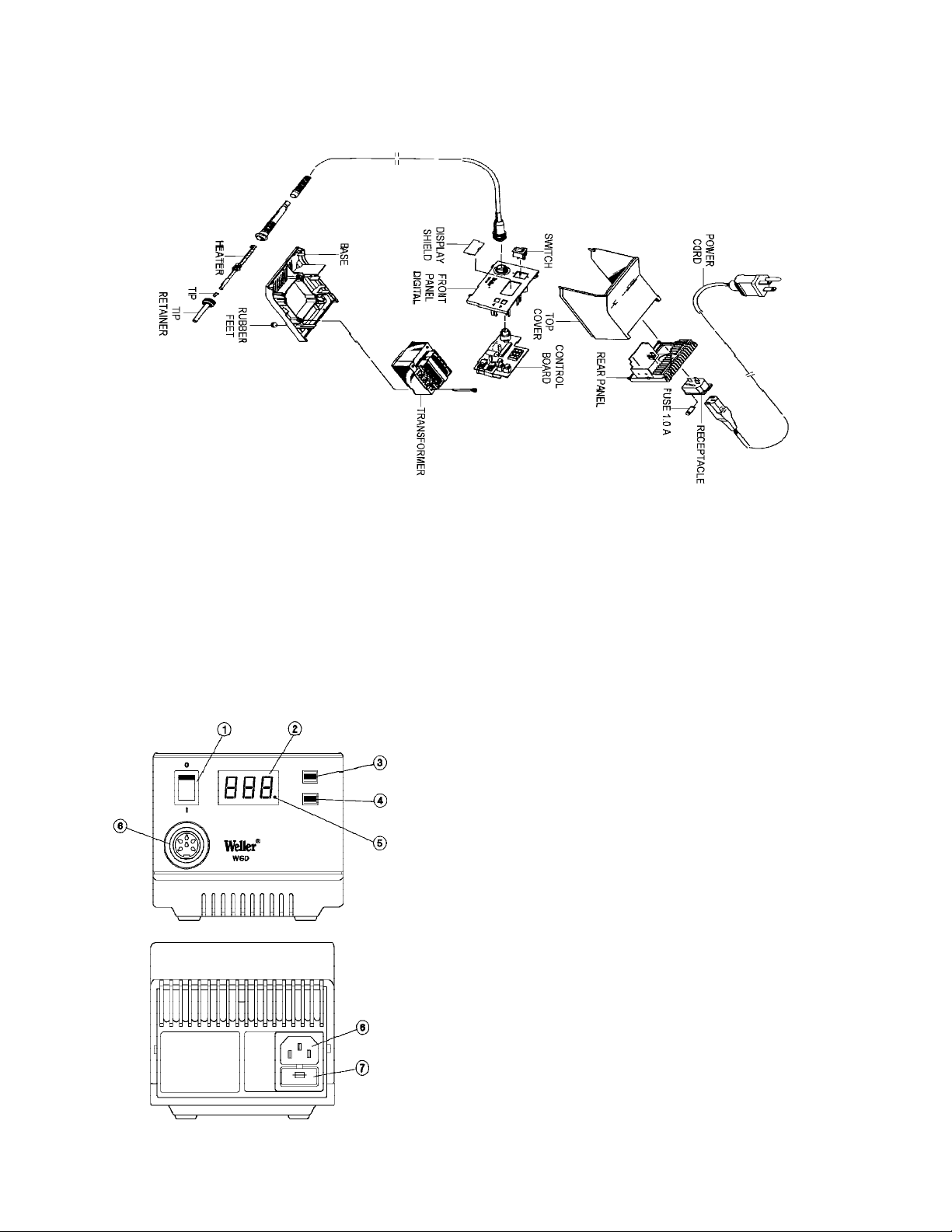
WSD80 EXPLODED VIEW
S1097ACH
REV. 11/01
WSD80 SOLDERING STATION
12
1. Power switch
2. Digital display
3. UP button
4. DOWN button
5. Optical regulator (LED)
6. Connection for soldering iron
7. Power supply connector
8. Fuse/Holder
WARNING: This product, when used for soldering
and similar applications, produces
chemicals known to the State of
California to cause cancer and birth
defects or other reproductive harm.
1
Page 2

DESCRIPTION
CONTROL UNIT
The soldering station WSD80 is a part of the range of products which was developed for industrial manufacturing as well as for
the repair and laboratory sector. A microprocessor makes operation simple and comfortable. The digital electronic control system
guarantees the best possible control performance for various soldering tools. The soldering tools themselves are recognized
automatically by the soldering station and assigned the corresponding control parameters. The high-powered 24 V heating
elements make excellent dynamic performance possible, so that the soldering tools can be used universally.
A grounded soldering iron tip, zero power switch and antistatic design of control unit and iron complete the high quality standard.
The possibility of connecting an external input unit further increases the variety of functions of this soldering station. With the
optional input units WCB1 and WCB2 it is possible to implement time functions, locking functions, etc. Integrated temperature
gauge and PC interface are included in the extended scope of the input unit WCB2.
The temperature is set in a range between 150°F and 850°F using the up/down keys. The set point and actual value are displayed
digitally. A blinking red LED in the display signals that the preset temperature has been reached - this serves as an optical
regulator. This station meets all applicable MIL-STD’s and the J-STD-001B standards.
NOTE: The WSD80 can also power and control most Weller Desoldering Irons. If the applied load is such that the
heater power remains full on for 20 minutes, the heater power will be reduced to 90%.
SOLDERING IRON
WSP80: The soldering iron WSP80 is characterized by its capacity for reaching the soldering temperature quickly and
precisely. Its slim design and heating power of 80 watts makes universal usage possible - from extremely
fine applications to high-temperature soldering work. Work can be continued immediately after switching
soldering tips, since the temperature is reached again quickly.
See “Accessories” for additional tools.
CAUTION: (For Removing Tip) turn station “OFF” before removing tip/retainer. Hold iron tip down to remove tip retainer
and tip.
REPLACMENT P ARTS
WSP80 Soldering Iron Complete
WSP80AP Soldering Iron w/Stand
WS101 Heater/Sensor
WS102 Tip Retainer
WS103 Handle/Cord*
WS104 Power Supply Cord*
WS106 Control Board
WS107 Transformer*
* Special Order
2
11
Page 3

ACCESSORIES
WSP80 Soldering iron set WSP80 (WSD80 only)
WST20 Thermal Stripping Tool with Support
WHP80 Heating Plate
WT50 Heated Tweezer
WCB1 Calibrator
WCB2 Calibrator
SCOPE OF SUPPL Y
Control unit
Soldering iron WSP80
Power cable
Operating instructions
Soldering iron rest
Illustration: Exploded view, see page 12.
10
TECHNICAL DA TA
Dimensions in mm: 166 x 155 x 101 (lxwxh)
Supply voltage (7): 120V 50/60 Hz
Power input: 95 watts
Fuse (8): 1 A (5mm x 20mm in power supply receptacle)
Temp. control: 150°F - 850°F
Stability: ±10°F from target value
STARTING
Assemble soldering iron stand. Place the soldering iron in the stand. Insert the soldering iron plug into the receptacle (6) of the
control unit and lock by turning to the right. Check that the power supply corresponds to the specifications on the nameplate and
that the power switch (1) is in the OFF position. Connect the control unit to the power supply. Switch on the unit at the power switch
(1). When the appliance is switched on, a self-test is carried out, during which all display elements (2) are in operation. Then the
set temperature (required value) and the temperature version (°C/°F) are briefly displayed. Thereupon, the electronic system
automatically switches over to the actual tip temperature display. A red LED (5) lights up in the display (2). This serves as an
optical control for heater firing. Constant illumination means that the system is overheating. The blinking light signals that the
operating temperature has been reached. A setback time of 20 minutes may be set by despressing the UP key while the station is
switched on; ON will be displayed to indicate the SETBACK mode is set. Repeat the procedure to disable the SETBACK feature;
OFF will be displayed.
3
Page 4

SETTING THE TEMPERA TURE
The digital display (2) shows the actual value temperature. By pressing the UP or DOWN key (3, 4) the digital display (2)
switches to the set point. The set point (“flashing display”) can be changed by tapping or by firmly pressing the UP or
DOWN button (3, 4) in the desired direction. Pressing the button will change the set point quickly. The digital display (2)
returns automatically to the actual value approximately 2 seconds after releasing the button.
MAINTENANCE
The transition between the heating element/sensor and the tip of the soldering iron may not come in contact with dirt,
foreign particles or become damaged, since this affects the precision of the temperature control.
INSTRUCTIONS FOR USE
For initial heating, coat the selective tinnable tip with solder. This removes any oxidation or dirt on the tip, which may have
occurred during storage. During pauses between soldering and before storing the soldering iron, ensure that the tip of the
soldering iron is well coated. Do not use aggressive fluxing agents.
Note: Always ensure the proper position of the soldering iron tip. When removing tip (HOLD TIP DOWN)!
These soldering irons have been adjusted for an average-size tip. Deviations can occur due to exchanging of the tip or using
other tip designs.
4
20. Attention.
Use only accessories or attachments which are listed in the accessories list of the Operation Manual. Use only
WELLER accessories or attachments on original WELLER equipment. Use of other tools and other accessories
can lead to danger of injury.
21. Repairs to your soldering tool should be carried out by a qualified technician.
This soldering tool is in accordance with the relevant safety regulations. Repairs should only be carried out by a
qualified electrician using original WELLER replacement parts. Failure to do so can lead to accidents for the
operator.
22. Do not work on electrically live parts.
The grip of antistatic designed soldering tools is conductive.
23. Applications with other WELLER equipment.
If the soldering tool is to be used together with other WELLER equipment and attachments, also observe the
warning notices given in the corresponding Operation Manual.
24. Observe the valid safety regulations for your workplace.
9
Page 5

14. Take care of your soldering tool.
Keep the soldering tool clean for better and safer work. Follow the maintenance instructions and the notices
concerning changing the soldering tips. Regularly inspect all connected cords and hoses. Repairs should only be
carried out by a qualified technician. Use only original WELLER replacement parts.
15. Remove the power plug from the socket before opening the unit.
16. Remove all maintenance tools.
Before switching on the unit, check that all maintenance tools have been removed from the unit.
17. Avoid unexpected operation.
Make sure that the power switch is turned off when inserting the plug into the socket or connecting to power.
Don’t hold a soldering tool which is connected to a power supply while touching the power switch.
18. Pay attention.
Be careful of what you do. Work with caution. Don’t use the soldering tool if you are not concentrating on your
work.
19. Inspect the soldering tool for any damage.
Before further use of the soldering tool, safety devices or slightly damaged parts must be carefully checked for
error-free and intended operation. Inspect moving parts for error-free operation and that they don’t bind, or whether
any parts are damaged. All parts must be properly mounted and all requirements fulfilled for guaranteed error-free
operation of the soldering tool. Damaged safety devices and parts must be repaired or replaced by a qualified
technician, so long as nothing else is indicated in the Operation Manual.
8
EXTERNAL INPUT UNIT WCB1 (OPTIONAL) AND WCB2 (OPTIONAL)
The following functions are possible when using an external input unit.
Offset: The real temperature of the soldering iron can be changed by ± 72°F/40°C by input of a temperature offset.
Setback: Locking of the set point temperature to 300°F/150°C (standby). The setback time can be set at 0-99
minutesafter the soldering station has switched to standby mode. The setback condition is indicated by
means of a flashing actual-value display and terminated by pressing a key or by cooling the tip on a wet
sponge. The set required value is briefly displayed.
Lock: Locking the set point temperature. Settings cannot be changed after the soldering station has been
locked.
°C/°F: Switching the temperature display from °C to °F, and vice versa. If the “Down” key is pressed when
switching on the station, the actual temperature version will be displayed.
Window: Setting a Lock temperature window. If the set point is locked, a window of adjustment of up to 179°F/99°C
may be set.
Cal: Re-adjustment of the soldering station (WCB1 only) and factory setting (FSE). Resetting all index values
to 0, temperature to 660°F.
PC Interface: RS232 (WCB2 only)
Temp. Gauge: Integrated temperature gauge for thermal element Type K (WCB2 only)
SAFETY INSTRUCTIONS
The manufacturer assumes no liability for uses other then those described in the operating instructions, or for unauthorized
alterations.
5
Page 6

These operating instructions and warnings should be read carefully and kept in an easily accessible location in the vicinity
of the soldering iron. Non-observance of these warnings can result in accidents, injury or risks to your health.
WARNINGS
1. Keep your work area in proper order.
Always return the soldering tool to its original holder when not in use. Do not bring combustible materials near
the hot soldering tools
2. Take care for the surroundings.
Don’t use the soldering tool in a moist or wet environment.
3. Protect yourself against electrical shocks.
Avoid touching grounded parts with your body, e.g. pipes, heating radiators, stoves or refrigerators.
4. Keep children at a distance.
Don’t allow other persons to touch or disturb the soldering tool or cord. Keep other persons away from your work
area.
5. Store your soldering tool in an appropriate place.
Unused soldering tools should be stored in a dry location which is out of the reach of children (some place high
or in a locked cabinet). Switch off all unused soldering tools.
6. Do not overload your soldering tool.
Use the soldering tool only with the specified voltage or specified pressure and pressure range.
7. Use the appropriate soldering tool.
6
Don’t use a soldering tool whose performance is not adequate for your work. Never use the soldering tool for
purposes for which it was not designed.
8. Wear suitable work clothes.
There is a danger of burning yourself with liquid solder. Wear the corresponding protective clothing in order to
protect yourself against burns.
9. Protect your eyes.
Wear protective eye wear. When working with bonding agents, it is particularly important to observe the warning
notices of the bonding agent manufacturer. Protect yourself to observe the warning notices of the bonding agent
manufacturer. Protect yourself against spattering solder. There is a danger of burning yourself with liquid solder.
10. Use a soldering vapor suction device.
If devices for solder vapor suction are available, ensure that these are connected and correctly used.
11. Do not use the cord for purposes for which it is not designed.
Never carry the soldering tool by the cord. Don’t use the cord to pull the power plug from the socket. Protect the
cord from heat, oil and sharp edges.
12. Protect the work piece.
Use clamping devices to hold the work in place. This is more secure than using your hands, and leaves both
hands free to work with the soldering tool.
13. Avoid abnormal posture.
Set-up your work place with proper ergonomics. Avoid bad posture when working. Always use the suitable
soldering tool.
7
 Loading...