

Page 1
WRK - Operating Instructions 1-9
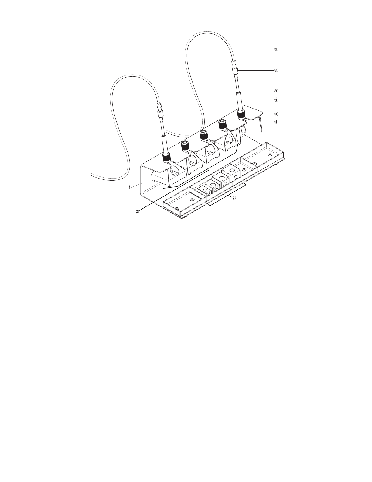
Device Overview
1 WRK Stand / Tool Holder
2 Reflow nozzle, large
3 Reflow nozzle, small
4 Tripod / Stand-Off
5 Clamping sleeve
6 Vacuum pick-up tool
7 Marker ring (Indicates Component Height)
8 Vacuum tube connector
9 Vacuum tube
10 Vacuum Cup with Heat Shield
Page 2

2-9 WRK
Contents
1 Instructions ................................................................................2
2 Cautions and Warnings! ............................................................2
3 Description of the WRK .............................................................3
4 Initial Setup................................................................................3
5 Using the WRK..........................................................................5
6 Accessories ...............................................................................7
7 Packing List ...............................................................................7
8 Disposal.....................................................................................7
9 Warranty ....................................................................................8
1 Instructions
Thank you for placing your trust in our company by purchasing the
Weller WRK.
This product meets or exceeds the requirements established by
Weller for superior performance, versatility and quality.
These instructions contain information to help you operate and
service the WRK safely and correctly.
Z Read these instructions in their entirety before working with the
WRK.
Z Keep these instructions in a place that is accessible to all users.
1.1 Additional Documents
− Please read the Operating Instructions of your Control Unit and
Safety Information booklet
2 Cautions and Warnings!
Please read the WRK Operating Instructions and the attached Safety
Information carefully prior to initial operation. Failure to observe the
safety warnings may result in accident, injury, or risk to health.
The manufacturer shall not be liable for damage resulting from
misuse of this product or unauthorized alterations.
Warning: This product when used for soldering and similar
applications, produces chemicals known to the State of California to
cause cancer and birth defects or other reproductive harm.
Page 3
WRK 3-9
2.1 Safety Information
Always place the Reflow Nozzles in the original holder
Remove all inflammable objects from the proximity of the hot
soldering tool.
Use suitable protective clothing to prevent the risk of burns
associated with molten solder.
Never work on electrically live circuits or components.
Always wear eye protection when working with soldering and
desoldering applications.
3 Description of the WRK
The Weller WRK Removal Kit optimizes the rework process and
enables SMT components to be removed precisely and without being
damaged.
The removal procedure can be optimized for each component size
between .120" and 1.181", (3 mm and 30 mm) with the aid of the
different reflow nozzles.
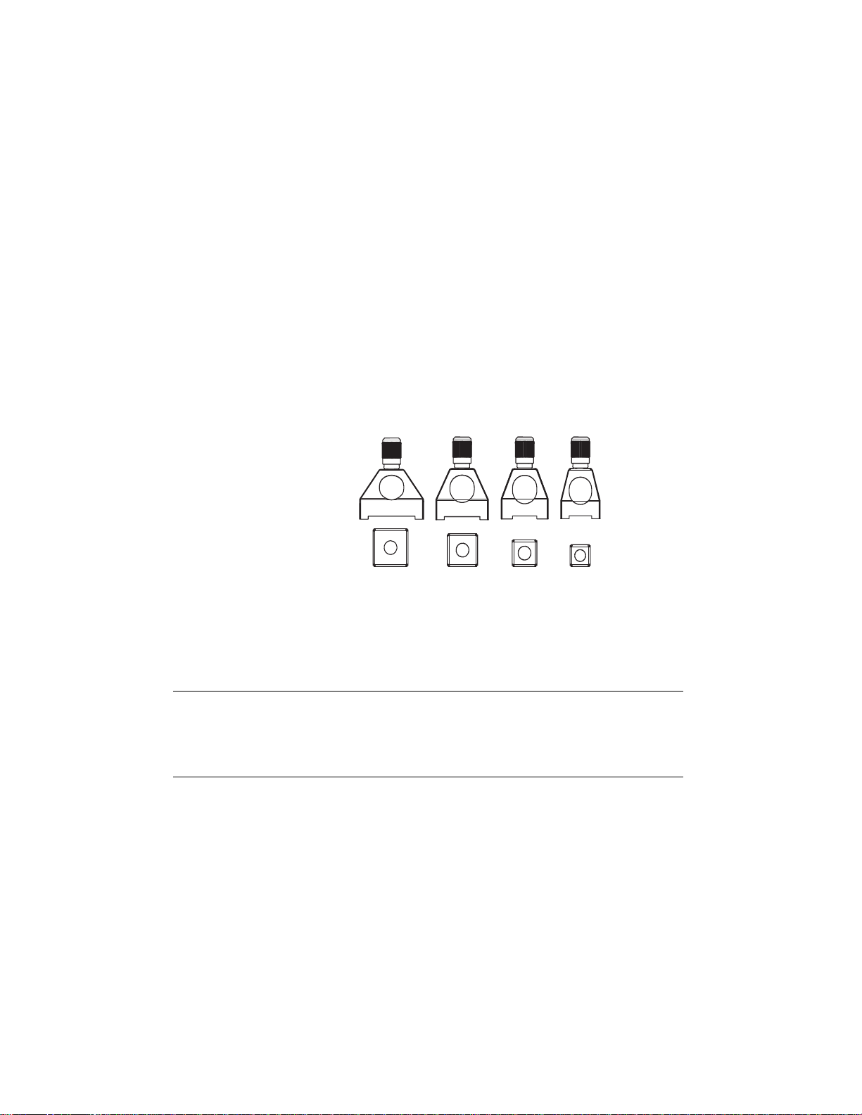
The reflow nozzles are suitable for the use of the HAP 1 and
HAP 200 Hot Air tools.
Suitable reflow nozzles for HAP 1 and HAP 200
ENFRITESPTNLSVDKFIGRTRCZPLHUSKSLEELVLT
WARNING!
•
Large
Reflow
nozzles
Small
Reflow
Nozzles
4 Initial Setup
Risk of injury due to incorrectly connected vacuum
hose.
Z Never connect the vacuum hose to the "Air“ port!
Page 4

4-9 WRK
Also read and observe the Operating Instructions of your control
Note
unit.
1. Carefully unpack the WRK.
2. Assemble reflow nozzles (2, 3), tripod (4) and pick-up tool (6) in
holder (1).
3. Switch off the control unit.
4. Connect the hot-air pencil (HAP) with air hose to the "Air“ outlet of
the control unit and insert with the attachment plug in the correct
connection socket of the repair station. Lock by turning clockwise
slightly (connect HAP 1 with adapter only).
5. Connect vacuum pick-up (6) with vacuum hose to the vacuum
pick-up ports of the control unit.
6. Attach a suitable reflow nozzle or tripod to the vacuum pick-up
(see Sections 5.1 and 5.2).
It is possible to use large reflow nozzles, small reflow nozzles with
tripod or the tripod on its own to lift off small components with the
vacuum pick-up tool.
4.1 Mounting the Reflow Nozzle
1. Check the .400 ", (10 mm) diameter vacuum pick-up tool to ensure
the components (clamping sleeve (5), marker ring (7) and vacuum
cup with heat shield (10)) are correctly installed.
2. Assemble nozzles directly to vacuum pick-up tool (6) using the
clamping sleeve (5).
Note The reflow nozzles are not assembled directly to the .180 ", (4.5
mm) vacuum pick-up tool. Ensure the tripod and the.180 ", (4.5 mm)
diameter vacuum pick-up tool are correctly positioned in the nozzle
and on the component.
4.2 Mounting the tripod
1. Check the .180 ", (4.5 mm) diameter vacuum pick-up tool to
ensure the components (clamping sleeve (5), marker ring (7) and
vacuum cup with heat shield (10)) are correctly assembled.
2. Screw tripod (4) to the vacuum pick-up tool (6) using the clamping
sleeve (5).
You can use the .180 ", (4.5 mm) diameter vacuum pick-up tool
mounted in this way with a Large reflow nozzle (A1) or with Small a
reflow nozzle (B1). When working without a reflow nozzle, you can
also use a .400 " (10 mm) diameter vacuum pick-up tool.
Page 5

WRK 5-9
5 Using the WRK
WRK operation during the component removal procedure is divided
into 3 steps:
1. Positioning the Vacuum Pick-up tool
2. Preparing for Component Pick-up
3. Reflow and Removal of the component
5.1 Positioning the Pick-up
A 1 B 1
ENFRITESPTNLSVDKFIGRTRCZPLHUSKSLEELVLT
The component to be reworked must be at least .08 " , (2 mm)
smaller than the diameter of the reflow nozzle used, otherwise the
component may be damaged.
Z Carefully position the large reflow nozzle (A1) or tripod with small
reflow nozzle (B1) with the vacuum pick-up tool over the
component and center the component within the nozzle.
Page 6

6-9 WRK
5.2 Preparing for Component Pick-up
1
2
A 2
B 2
Note Pictures are for illustration use only. Vacuum hose must be
connected and activated for the vacuum pick-up tool to operate.
1. Carefully position the vacuum pick-up tool with mounted reflow
nozzle, (A2) or with the tripod, (B2) over the component.
2. Carefully press the vacuum pick-up tool down .120- .400 ", (3-5
mm) over the component (1) without damaging the component.
3. Switch on the vacuum on the control unit and subject the
component to suction.
4. Slide the marker ring in this position downwards (2).
The marker ring indicates whether the component subjected to
suction is raised (rubber = at top) or not raised (rubber = at
bottom).
5.3 Reflow and Removal of the Component
A 3 B 3
A 4 B 4
Page 7

WRK 7-9
1. Position the vacuum pick-up tool over the componet (see 5.1) and
prepare desoldering (see 5.2).
2. Feed the hot-air tool from the side through the designated nozzle
opening up to the component and actuate the hot air tool until the
component is reflowed and raised by the vacuum pick-up tool (see
5.3).
The marker ring is now in the upper position.
3. Remove the hot-air tool and switch off.
4. Position the vacuum pick-up tool together with the nozzle and the
removed component on a heat resistant surface.
5. Carefully press the vacuum pick-up tool downwards and switch off
the vacuum. Wait several seconds for the component to release
before moving the tool
Note You can also work without a reflow nozzle, e.g. in the case of
components larger than 1.180 ", (30 mm).
6 Accessories
0051515499 WRK holder
0058761730 Nozzle set 33x33/24x24 with pick-up
0058761731 Nozzle set 27x27/20x20 with pick-up
0058761732 Nozzle set 18/15.5/12.5/10 with pick-up
7 Packing List
ENFRITESPTNLSVDKFIGRTRCZPLHUSKSLEELVLT
• WRK consisting of :
• Holder.
• 180 " (4.5 mm) diameter Pick-up
• .400 ", (10 mm) diameter Pick-up
• Tripod
• Reflow nozzles:
• Large (33x33 mm, 27x27 mm, 24x24 mm, 20x20 mm)
• Small (18x18 mm, 15.5x15.5 mm, 12.5x12.5 mm,
10x10 mm)
• 3 suction inserts each for .180 " (4.5 mm) diameter and .400 " (10
mm) diameter
• 2 vacuum hoses with connector
• Operating Instructions for WRK removal kit
8 Disposal
Dispose of replaced equipment parts, filters or old devices in
accordance with the rules and regulations applicable in your country.
Page 8

8-9 WRK
9 Warranty
Cooper Hand Tools warrants to the original purchaser and any
subsequent owner (“Buyer”) that Weller soldering and desoldering
products will be free from defects in material and workmanship for a
period of one year from date of purchase, provided that no warranty
is made with respect to products which have been altered, subjected
to abuse or improperly used, installed or repaired. Use of nonCooper Hand Tools components will void this warranty if a nonCooper Hand Tools component is defective (or is the source of the
defect). Cooper Hand Tools will repair or replace products found to
be defective not caused by a part, component or accessory
manufactured by another company, during the warranty period.
Contact Cooper Hand Tools with dated proof of purchase and return
to Cooper Hand Tools, 1000 Lufkin Road, Apex, NC 27539. All costs
of transportation and reinstallation shall be borne by Buyers.
IN NO EVENT SHALL COOPER HAND TOOLS BE LIABLE FOR
INCIDENTAL OR CONSEQUENTIAL DAMAGES. COOPER HAND
TOOLS LIABILITY FOR ANY CLAIMS ARISING OUT OF THIS
WARRANTY SHALL NOT EXCEED THE PURCHASE PRICE OF
THE PRODUCT.
THE PERIOD OF ALL IMPLIED WARRANTIES APPLICABLE TO
THIS PRODUCT INCLUDING ANY IMPLIED WARRANTY OF
MERCHANTABILITY OR FITNESS, OR FITNESS FOR A
PARTICULAR PURPOSE IS LIMITED TO 12 MONTHS FROM THE
DATE OF PURCHASE BY THE USER.
Some states do not allow the exclusion or limitation of incidental or
consequential damages, so the above limitation or exclusion may not
apply to you. Some states do not allow limitation on how long an
implied warranty lasts, so the above limitation may not apply to you.
This warranty gives you specific legal rights, and you may also have
other rights, which vary, from state to state.
Page 9

WRK 9-9
www.Cooperhandtools.com
Weller is a registered Trademark and registered Design of Cooper
Industries, Inc.
U.S Mailing Address:
Cooper Hand Tools
P.O. Box 728
Apex, NC 27502-0728
U.S Shipping Address:
1000 Lufkin Road
Apex, N.C. 27539
Tel: (919) 387-0099
Fax: (919) 387-2379
For inquiries concerning Technical /
Customer Service please call:
(800) 476-3030 Ext. 1
Canada Shipping Address:
Cooper Tools
164 Innisfil Street
Barrie, Ontario
Canada L4N 3B7
Attn: Repairs
Fax: 1-800-403-TOOL (8665)
Phone: 705-728-5564 Ext. 2026
ENFRITESPTNLSVDKFIGRTRCZPLHUSKSLEELVLT
005 XX XXX XX / 03.07 © 2007 Cooper Industries
 Loading...