

Page 1
WDH 10T / WDH 20T Operating Instructions 1-7
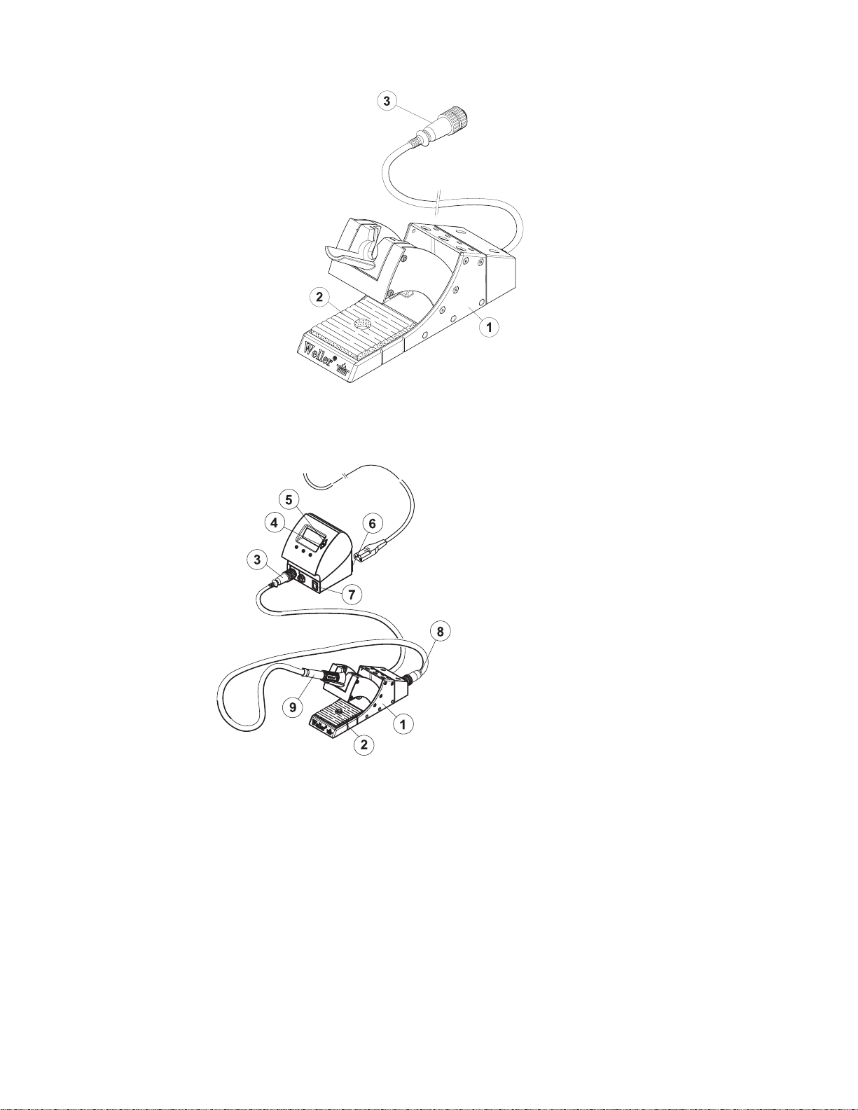
Equipment Overview
Connection Instructions:
1 Switching Tool Stand
2 Sponge
3 Switching Tool Stand Plug
4 Down Scroll Key
5 Up Scroll Key
6 Receptacle 120 VAC
7 Power Switch
8 Soldering Iron Plug
9 Soldering iron
Page 2

2-7 WDH 10T / WDH 20T
Thank you for placing your trust in our company by purchasing the
Weller WDH 10T / WDH 20T Switching Tool Stand.
This product meets or exceeds the requirements established by
Weller for superior performance, versatility and quality.
1. Cautions! / Warnings!
Please read these Operating Instructions and the attached Safety
Information carefully prior to initial operation. Failure to observe the
safety warnings may result in accident, injury, or risk to health.
The manufacturer shall not be liable for damage resulting from
misuse of the machine or unauthorized alterations.
Warning: This product when used for soldering and similar applications, produces chemicals known to the State of California to cause
cancer and birth defects or other reproductive harm.
Safety Information:
Always place the soldering iron in its original holder
Remove all inflammable objects from the proximity of the hot
soldering tool.
Use suitable protective clothing to prevent the risk of burns asso-
ciated with molten solder.
Never leave a soldering/desoldering tool unattended.
Never work on electrically live circuits or components.
Always wear eye protection when working with soldering and
desoldering applications.
The Weller WDH 10T / WDH 20T Switching Tool Stand corresponds
to the EC Declaration of Conformity in accordance with the basic
safety requirements of Directives 89/336/EEC and 73/23EEC.
1.1 Additional Documents
− Operating Instructions of your control unit including the
accompany booklet on Safety Instructions
− Operating Instructions of your soldering tool
1.2 Intended use
Always use the Switching Tool Stand WDH 10T / WDH 20T
exclusively for placing the listed Sodering Tool, (See Technical Data)
as specified in these Operating Instructions. Specified use of the
Switching Tool Stand WDH 10T / WDH 20T also includes:
− observance of these Operating Instructions,
− observance of all other accompanying documentation,
Page 3
WDH 10T / WDH 20T 3-7
− observance of the locally applicable accident prevention
regulations.
The manufacturer shall not be liable for damage resulting from
unauthorized alterations to the device.
2 Description
The Weller WDH 10T / WDH 20T Switching Tool Stand, as opposed
to a standard Tool Stand, provides a switching function that is
activated by the soldering station. A microswitch integrated in the
Switching Tool Stand is actuated when the soldering tool is placed in
the holder or removed.
When the Switching Tool Stand is placed into a Digital Weller
Soldering Station the Tool Stand and the Temperature SETBACK
functions are automatically detected.
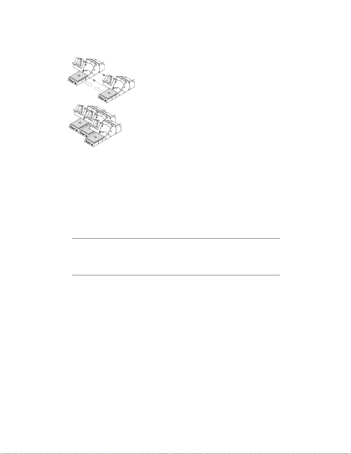
Several Switching Tool Stands can be connected together at the
side.
Technical Data WDH 10T / WDH 20T
Dimensions L x W x H (inches): 8.189 x 2.56 x 4.53
L x W x H (mm): 208 x 65 x 115
Weight 1.52 lb. ( 0.69 kg )
Matching soldering
tools
Compatible
control units
WDH 10T: WP80, WSD161,WSD151,
WSP80
WDH 20T: WMP
WSD81, WSD161, WDD81V, WSL, WSL2,
WAD101, WMRS, WRS1002, WRS3000,
WD1, WD2, WD1M, WD2M, WR 3M
WARNING!
•
3 Placing into Operation
Risk of burns when working with soldering tools
There is a risk burning if you touch the hot soldering tool.
Z Always place the soldering iron in the Switching Tool Stand.
1. Carefully unpack the Switching Tool Stand.
2. Ensure that the soldering station to be connected to is off.
3. Insert the 7-pin plug (3) of the Switching Tool Stand connecting
cable at the soldering station tool receptacle and lock it by turning
clockwise slightly.
Page 4

4-7 WDH 10T / WDH 20T
r
r
4. Place the soldering iron (9) in the Switching Tool Stand (1) and
insert the soldering iron 7-pin plug (8) into the Switching Tool
Stand receptacle and lock it by turning clockwise slightly.
5. Switch on the soldering station (7).
4 Operating Guidelines
4.1 Temperature decrease (SETBACK) and
automatic switch-off time (AUTO-OFF) with
connected Switching Tool Stand
The SETBACK time and AUTO-OFF time can be set at the control
unit (WD1, WD2, WD1M, WD2M and WR 3M units), or are
permanently specified (WSD and WRS units).
After placing the soldering tool in the Switching Tool Stand, the
temperature decreases and/or the system shuts down, depending on
the setting at the control unit. The respective switching action is
displayed in the following table.
Tab. 1. Temperature and switch-off action of the control units WD1, WD2, WD1M, WD2M,
Tab. 2. WR 3M, WSD and WRS with different settings of the SETBACK and AUTO-OFF functions
Possible settings at the control
SETBACK time
[1-99 mins]
1)
unit
OFF time
[1-999 mins]
0 0 The soldering tool is switched off in the holder2).
ON 0
0Time
ON Time
Temperature switching action after placing the soldering tool in the
Switching Tool Stand
2)
The soldering tool is regulated in the holder
temperature
3)
.
The soldering tool is switched off in the holder
down to STANDBY
2)
after the OFF time
has elapsed.
The soldering tool is regulated in the holde
temperature
3)
and is switched off after the OFF time has elapsed.
2)
down to the STANDBY
2)
Time 0
Time Time
The soldering tool is regulated in the holder
temperature
The soldering tool is regulated in the holde
temperature
3)
after the SETBACK time has elapsed.
3)
after the SETBACK time has elapsed and is switched
down to STANDBY
2)
down to the STANDBY
off after the OFF time has elapsed.
1)
With the WSD and WMD devices, only the settings 0/0 and ON/TIME are possible, whereby the respective
time values for SETBACK (20 minutes) and AUTO-OFF (60 minutes) are permanently specified. With
these device types, deviating SETBACK times are only possible with the external input device WCB2.
2)
Outside the Switching Tool Stand, the soldering tool always remains at the set specified temperature.
The holder function is activated after the first time the soldering tool is deposited.
3)
The STANDBY temperature must be below the set specified temperature; otherwise the SETBACK
function is inactive.
Page 5

WDH 10T / WDH 20T 5-7
Note Observe the Operating Instructions of your control unit when setting
and switching the SETBACK and AUTO-OFF functions on and off.
4.2 Switching valve control with Switching Tool
Stand on/off (WAD101)
When operating a soldering iron with inert gas and when using the
Switching Tool Stand, the valve control must be set at the WAD 101
control unit. Two switching conditions are possible:
− A-1: the valve control is switched on. The valve is activated by the
Switching Tool Stand with the ON/OFF function. In this operating
condition, the SETBACK function "OFF" is not available.
− A-0: the valve control is switched off. The SETBACK function is
available without restrictions.
Note Observe the Operating Instructions of your control unit when
setting the valve control function.
5 WDH 10T / WDH 20T: maintenance and
care
The sponge should be cleaned regularly to remove solder residue
using distilled water only.
6 Fault messages and corrective actions
Message/Symptom Possible cause Corrective measures
Soldering iron does not
switch off after being placed
in the holder
Soldering iron no longer
switches on after removal
from holder
SETBACK time on the
soldering station is activated
The holder is not correctly
connected
Movable funnel or shift linkage
is jammed
Soldering iron only switches off
after the set time:
Z Set the SETBACK time on the
soldering station to 0.
Z Check connecting cable
- Holder cable to soldering
station
- Soldering iron to holder
Check funnel and shift linkage
Page 6

6-7 WDH 10T / WDH 20T
7 Accessories
Dry cleaning insert WDC 2, 0051512599
Spiral wool, 0051382599
8 Packing List
WDH 10T
− 0051516199 Switching Tool Stand WDH 10T
− Operating Instructions WDH 10T / WDH 20T
WDH 20T
− 0051516299 Switching Tool Stand WDH 20T
− Operating Instructions WDH 10T / WDH 20T
9 Disposal
Dispose of replaced equipment parts, filters or old devices in
accordance with the rules and regulations applicable in your country.
10 Warranty
Cooper Hand Tools warrants to the original purchaser and any
subsequent owner (“Buyer”) that Weller soldering and desoldering
products will be free from defects in material and workmanship for a
period of one year from date of purchase, provided that no warranty
is made with respect to products which have been altered, subjected
to abuse or improperly used, installed or repaired. Use of nonCooper Hand Tools components will void this warranty if a nonCooper Hand Tools component is defective (or is the source of the
defect). Cooper Hand Tools will repair or replace products found to
be defective not caused by a part, component or accessory
manufactured by another company, during the warranty period.
Contact Cooper Hand Tools with dated proof of purchase and return
to Cooper Hand Tools, 1000 Lufkin Road, Apex, NC 27539. All
costs of transportation and reinstallation shall be borne by Buyers.
IN NO EVENT SHALL COOPER HAND TOOLS BE LIABLE FOR
INCIDENTAL OR CONSEQUENTIAL DAMAGES. COOPER HAND
TOOLS LIABILITY FOR ANY CLAIMS ARISING OUT OF THIS
WARRANTY SHALL NOT EXCEED THE PURCHASE PRICE OF
THE PRODUCT.
THE PERIOD OF ALL IMPLIED WARRANTIES APPLICABLE TO
THIS PRODUCT INCLUDING ANY IMPLIED WARRANTY OF
MERCHANTABILITY OR FITNESS, OR FITNESS FOR A
PARTICULAR PURPOSE IS LIMITED TO 12 MONTHS FROM THE
DATE OF PURCHASE BY THE USER.
Page 7

WDH 10T / WDH 20T 7-7
Some states do not allow the exclusion or limitation of incidental or
consequential damages, so the above limitation or exclusion may
not apply to you. Some states do not allow limitation on how long an
implied warranty lasts, so the above limitation may not apply to you.
This warranty gives you specific legal rights, and you may also have
other rights, which vary, from state to state.
www.Cooperhandtools.com
Weller is a registered Trademark and registered Design of Cooper
Industries, Inc.
U.S Mailing Address:
Cooper Hand Tools
P.O. Box 728
Apex, NC 27502-0728
U.S Shipping Address:
1000 Lufkin Road
Apex, N.C. 27539
Tel: (919) 387-0099
Fax: (919) 387-2379
For inquiries concerning Technical /
Customer Service please call:
(800) 476-3030 Ext. 1
Canada Shipping Address:
Cooper Tools
164 Innisfil Street
Barrie, Ontario
Canada L4N 3B7
Attn: Repairs
Fax: 1-800-403-TOOL (8665)
Phone: 705-728-5564 Ext. 2026
005 XX XXX XX / 03.07 © 2007 Cooper Industries
 Loading...