

Page 1
WWDD22MM // WWDD22000000M
M
OOppeerraattiinngg IInnssttrruuccttiioonns
s
Page 2

TTaabbllee ooff ccoonntteenntts
s
PPaagge
e
1. WD2M Detailed View 1
2. Cautions / Warnings 2
3. Description 2
4. Technical data / LCD Display 3
5. Placing into Operation 4
6. Channel Selection 4
7. Special Functions 5
8. USB Interface 9
9. Operating Guidelines 9
10. Accessories 9
11. Packing List 9
12. WMRP Soldering Iron 10
13. RT Style Tips 12-13
14. WMRT Tweezers 14
15. WMRT Tips 16
16. WD2M Circuit Diagram 18
17. WD2M Exploded View 19
Page 3
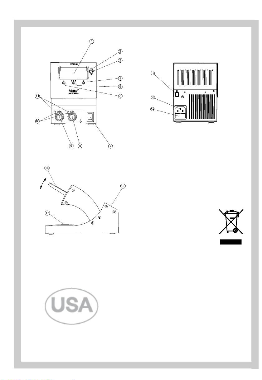
1. LCD Display
2. UP Scroll Key
3. DOWN Scroll Key
4. Radio Button / Channel 2 Selector
5. Radio button ( I - II - III ) Selector
6. Radio Button / Channel 1 Selector
7. Power Switch
8. Soldering Iron Receptacle Channel 2
9. Soldering Iron Receptacle Channel 1
10. LED Channel Selection Indicator
11. LED Heat Indicator
12. USB Port
13. Power Unit Receptacle
14. Primary Fuse
15. Soldering Tool Holder
16. Soldering Stand (Tip Storage)
17. Tray / Sponge
1. WD2M Detailed View
1
1
Page 4

2
2
Thank you for placing your trust in our company by
purchasing the Weller WD2M / WD2000M. This product
meets or exceeds the requirements established by
Weller for superior performance, versatility and quality.
22.. CCaauuttiioonnss!! // WWaarrnniinnggss!
!
Please read these Operating Instructions and the
attached Safety Information carefully prior to initial
operation. Failure to observe the safety warnings may
result in accident, injury, or risk to health.
The manufacturer shall not be liable for damage resulting from misuse or unauthorized alterations of the
equipment.
Warning: This product when used for soldering and
similar applications, produces chemicals known to the
State of California to cause cancer and birth defects or
other reproductive harm.
SSaaffeettyy IInnffoorrmmaattiioonn:
:
● Always place the soldering iron in its original
holder
● Remove all inflammable objects from the proximity of the hot soldering tool.
● Use suitable protective clothing to prevent the risk
of burns associated with molten solder.
● Never leave a hot soldering iron unattended.
● Never work on electrically live circuits or com-
ponents.
● Always wear eye protection when working with
soldering and desoldering applications.
The Weller microprocessor-controlled soldering station
WD2M / WD2000M corresponds to the EC Declaration
of Conformity in accordance with the basic safety
requirements of Directives 89/336/EEC and 73/23EEC.
33.. DDeessccrriippttiioon
n
33..11 CCoonnttrrooll uunniit
t
The microprocessor-controlled 2-channel soldering
station WD2M is part of a generation of devices developed for industrial electronic production, including
repair and laboratory applications. Digital electronic
controls, a precision sensor and heat transfer technology in the soldering tool provides precise temperature
control of the soldering tip.
Fast and precise sensor sampling in the closed loop
control provides tip temperature accuracy and maximum temperature control under load. The soldering
tools are recognized automatically by the WD2M and
the appropriate control parameters are set.
A Factory Control Check function, an Offset value input
option, programmable temperature decrease (Setback )
along with Standby and Lock functions enhance the
functionality of this unit.
The desired temperature can be set in the range
150 °F – 850 °F (50 °C – 450 °C). “Set” and “Read”
(actual tip temperature) values are displayed digitally.
Three Radio Buttons (4) (5) (6) are used for selection of
fixed/preset temperatures. The Heater Control
Indicator flashes (“
~” symbol in the display) when
the “Set” temperature is reached.
33..22 UUSSBBPPoorrt
t
The WD2M has a USB port for remotely controlling the
soldering station and temperatures can be read and
printed using a standard PC and PC software.
33..33 TTooooll SSttaannd
d
When not in use, the soldering iron should always be
placed in the Tool Stand.
The Tool Holder (14) for the soldering iron has four different settings, (30-80°) and can be moved to an operator’s preferred position without the use of tools. Areas
have been provided on the rear (15) of the Tool Stand
for placing the soldering tip when not in use. The base
of the Tool Stand contains a sponge (16) for cleaning
the soldering tips. (Note: LT tips require tip retainer for
storage in Tool Stand.)
33..44.. SSoollddeerriinngg iirroonns
s
WWMMRRP
P
An extremely powerful 40 W fine soldering iron with
the heating system integrated into the soldering tip.
Thanks to a plug-in system, the soldering tip can be
changed without tools. The soldering tip temperature is
reached rapidly and controlled precisely. Thanks to a
sensor installed in the handle, the soldering iron is
shut off automatically when it is placed in the WMRH
holder. Note: Minimun Tool Temperature 200 °F 100 °C.
WWMMRRT
T
The Weller WMRT Tweezers are designed for rework
and repair of precision SMT electronic devices. The
desoldering tip set can be quickly and easily changed
without the use of tools.
The tips are pre-aligned and
additional alignment is not required. The integrated (2
X 40 W) heating elements ensure that the desoldering
tip temperature is reached ver
y quickly and controlled
precisely. The desoldering tweezers are switched off
automatically when placed in the WMRTH tool holder.
Note: Minimun
T
ool
T
emperature 200
°F 100 °C.
E
nglish
Page 5
3
3
English
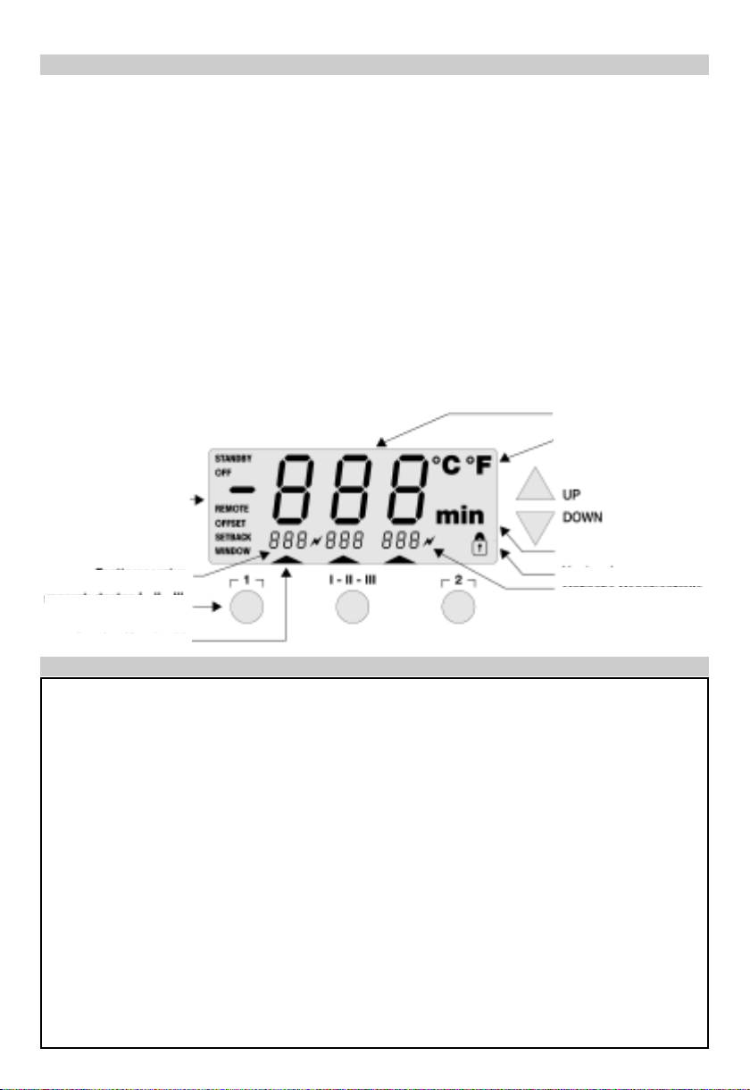
Active Channel Indicator
Dimensions: 5.27” L x 4.27” W x 5.77” H; (134mm L x 108mm W x 147mm H)
Primary voltage: 120 VAC / 50/60 Hz
Power Input: 85 Watts
Power Output: 24VAC
Fuse (10): T1.0A (120 VAC) (5 x 20mm)
Temperature Control: 150 °F – 850 °F (50 °C – 450 °C); WSP150 : 999 °F ( 550 °C )
WMRP and WMRT Tools - 200 °F – 850 °F (100 °C – 450 °C)
Temperature Accuracy: ±17 °F (±9°C)
Temperature Stability: ±9 °F (±5°C)
Meets or Exceeds: IPC / EIA J-STD-001C (Appendix A ) Commercial Soldering Standard
( Specific to WMRP / WMRT Soldering and Desoldering Tools )
Tip to Ground Resistance < 2 Ω ( Specific to the WSP80 / WP80 / WMP / WTA50 Soldering / Desold-
ering Tools )
Tip to Ground Millivolt Potential < 2 mV ( Specific to the WSP80 /
WP80 /
WMP / WTA50 Soldering / Desold-
ering Tools )
Temperature display
Temperature Symbol
Time Functions Indicator
Station Lock Indicator
Heater Control Indicator
Special Functions
“Menu 1”
3 Pre-Selected Temperatures
3 Radio Buttons
Scroll Key
Scroll Key
LCD Display
4. Technical Data
WWPP8800 ((OOppttiioonnaall)):
:
The WP80 Soldering iron is characterized by fast heatup and precise control of the soldering tip. Due to its
slim design, 80W heater output and short reach (tip to
grip), this tool can be used for a variety of applications,
from extremely fine soldering tasks to those requiring
high temperatures.
WWMMPP ((OOppttiioonnaall)):
:
The WMP Micro Soldering Iron’s very fast heat-up time
and short reach (tip to grip), makes it ideal for precision SMT electronics. The short distance between the
grip and soldering tip makes precise handling of the
65W soldering iron possible while performing very fine
soldering tasks.
WWTTAA5500 (( OOppttiioonnaall )) :
:
The WTA50 Desoldering Tweezers were designed
specifically for desoldering SMT components. Two heating elements (2 x 25W), each with its own temperature
sensor, maintain the same temperature on both tweezer
tips.
WWSSPP115500 (( OOppttiioonnaall )) :
:
The WSP150 Soldering iron is an especially powerful
tool for soldering tasks with extremely highheat
requirements. ( Note: Only one channel is active when
this Soldering iron is used. )
See Accessories for a list of other soldering tools that
can be connected.
Page 6
4
4
English
55.. PPllaacciinngg iinnttoo OOppeerraattiioon
n
Take care when unpacking the unit and accessories.
Place the soldering tools in the safety rest. Insert the
soldering iron plug into the connection socket (8) and
(9) of the control unit and lock by turning slightly to the
right. Verify the supply voltage matches the specification on the Base Unit Label and that the Power Switch
(7) is Off. Connect the control unit to the receptacle (12)
on the rear of the control unit and plug into a properly
grounded receptacle. Switch On the unit at the Power
Switch (7). The unit performs a self-test when it is
switched “On”, whereby all LCD Icons are briefly displayed (1).
Following this, the “Set” temperature of the active
channel is displayed for a brief period. The electronic
system then switches automatically to the “Read”
value. The "
~" symbol appears and the three fixed
temperatures of Radio Buttons
11 ,II--IIII--IIIIII,
,
and
2
2
are dis-
played. The "
~" symbol serves as a Heater Control
Indicator. The “Set” temperatures for channel 1 and 2
appear in small form in the display. The “Active” channel is labeled with an arrow underneath it. In addition
to this, the displayed channel is indicated by a red LED
next to the connection socket. The "
~" symbol and the
green LED on the connection socket are used as a visual control check. Flashing indicates the “Set” temperature has been reached and the tool has stabilized.
66.. CChhaannnneell SSeelleeccttiioon
n
When the channel selection Radio Button
11
or
2
2
is
depressed, the display shows the “Set” value of the
selected channel. The active channel in the display is
indicated with an arrow underneath it. In addition to
this, the displayed channel is indicated by a red LED
over the connection socket.
The displayed channel can be switched off by simultaneously pressing the
UUP
P
and
DDOOWWN
N
buttons (2) (3). This
is confirmed in the display with
OOFFF
F
.
To activate a deactivated channel, select it using the
channel selection button, if necessary, and simultaneously press the
UUP
P
and
DDOOWWN
N
buttons (2) (3) to switch
it on. The actual value appears in the display.
66..11 TTeemmppeerraattuurree sseettttiinng
g
66..11..11 SSeettttiinngg TTeemmppeerraattuurree wwiitthh UUpp//DDoowwnn SSccrroollll KKeeyys
s
As a rule, the main display (1) shows the tip temperature (“Read”) value. By depressing the
UUP
P
or
DDOOWWN
N
Scroll Keys (2 & 3), the display switches to the currently
“Set” value. The temperature symbol flashes
°°F
F
(or
°°CC)).
.
The “Set” value can now be changed by tapping or
holding in the
UUP
P
or
DDOOWWN
N
Scroll Key (2) (3). If the
Scroll Key is held depressed, the “Set” value changes
rapidly. Approximately 2 seconds after the Scroll Key is
released, the display switches automatically back to the
“Read” value.
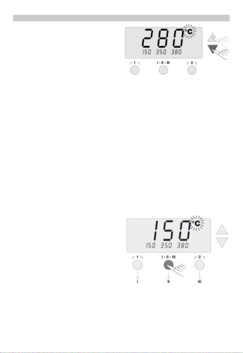
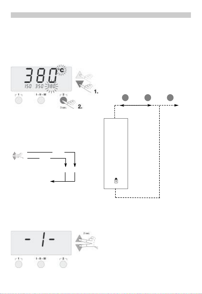
66..11..22SSeettttiinngg TTeemmppeerraattuurree wwiitthh tthhee RRaaddiioo BBuuttttoonnss 11,
,
II--IIII--IIIIII,, 2
2
The “Set” value for the temperature can be changed via
the three Radio Buttons 1, I-II-III, 2 .
Default settings:
1
1
300 °F ( 150 °C)
II--IIII--IIIII
I
662 °F ( 350 °C)
2
2
716 °F ( 380 °C).
By depressing a Radio Button, the pre-selected value
for that button now becomes the “Set” temperature.
The new value appears for Approximately 2 seconds in
the display and the temperature symbol flashes
°°FF (
(
or
°°CC)
)
. The display then switches back automatically to the
“Read” value.
66..11..33 CChhaannggiinngg PPrreesseett VVaalluueess ooff RRaaddiioo BBuuttttoonnss 11,, II--IIII--IIIIII,
,
22
The 3 Radio Buttons
11,, II--IIII--IIIIII,, 2
2
can be preset with tem
-
perature values as desired.
Depress the
UUP
P
or
DDOOWWN
N
Scroll Key to set a desired
temperature (see 6.1.1) in the large display. The
°°F
F
(or
Page 7
5
5
English
°°CC))
temperature symbol flashes
.
.
Next, depress and hold the desired Radio Button
11,, II--IIII-
-
IIIII
I
or
2
2
. While the button is depressed, the small display
assigned to the Radio Button also flashes and, after 3
seconds, accepts the value of the large display.
Release the Radio Button.
Setting a Radio Button to a low temperature gives you
the option of manually and quickly decreasing temper-
ature when the soldering iron is not being used.
77.. SSppeecciiaall ffuunnccttiioonnss
The special function are split in two menu sections.
Special functions menu 1: often used functions like
STANDBY, OFFSET, SETBACK, ...
Special functions menu 2: Calibration function, Remote
Id
77..11 SSppeecciiaall ffuunnccttiioonnss mmeennuu 1
1
Select the desired channel (CH1 or CH2) for inputting
the special functions. If the
UUP
P
and
DDOOWWN
N
buttons are
pressed simultaneously, after approx. 2 seconds the
menu selection for the special functions is activated
and -
I
I
- appears in the display, release buttons.
The following set-
tings are possible:
OFFSET, STANDBY, WINDOW (temperature settings);
SETBACK, OFF (time settings); Lock function (On/Off);
Temperature scale ( °F /°C ).
Radio Buttons
1
1
and I-II-I
III
I
are used for menu item
selection.
Radio Button
2
2
is used to exit the menu.
RReesseettttiinngg tthhee SSttaattiioonn ttoo FFaaccttoorryy SSeettttiinnggss:
:
Depress and hold Radio Button
2
2
. Then depress the
UUP
P
and
DDOOWWN
N
Scroll Keys at the same time. "
FFSSE
E
",
“Factory Setting Enabled” appears in the display. The
soldering station is now reset to its factory default settings.
77..11..11 SSttaannddbbyy TTeemmppeerraattuurre
e
When the Setback time has elapsed, the “Set” temperature is decreased automatically to the Standby value.
The “Read” temperature is displayed (flashing) and
"
SSTTAANNDDBBY
Y
" appears in the display. The Standby temperature can be set in the range ( 200 - 600°F/100 300°C ).
Adjust the standby temperature with the
UUP
P
or
DDOOWWN
N
Scroll Keys.
Switch to the previous menu item with Radio Button
1
1
.
Switch to the next menu item with Radio Button I-II-I
III
I
.
SSTTAANNDDBBY
Y
OOFFF
F
OOFFFFSSEET
T
SSEETTBBAACCK
K
WWIINNDDOOW
W
°°CC//°°F
F
11 II--IIII--IIIIII 22EEXXIIT
T
-1- -2-
2 (EXIT)
4 sec.
2 sec.
Menu Selection Exit
Page 8

6
6
E
nglish
77..11..22 AAuuttoo OOffff TTiimmee ((““OOFFFF””)
)
When the soldering tool is not in use, it is automatically
switched off after the “OFF” time has elapsed. The Auto
Off time can be set from 0 – 999 minutes. With a setting
of "0 min", the Auto Off function is disabled. Auto Off is
carried out independently of the Setback function. The
“Read” temperature is displayed (flashing) and may be
monitored as a decreasing heat indicator; "
OOFFF
F
"
appears in the display. Below 122°F ( 50°C ), a flashing
dash appears in the center of the display.
Change the “OFF” time with the
UUP
P
or
DDOOWWN
N
Scroll Keys.
Switch to previous menu item with Radio Button
1
1
.
Switch to next menu item with Radio Button
II--IIII--IIIIII
.
77..11..33 TTeemmppeerraattuurree OOffffsseet
t
The actual soldering tip temperature can be changed
±72°F/±40°C by the input of a temperature offset. The
Offset function is used to match the station display to
the tip temperature when measured with an external
instrument.
Change the “Offset” value with the
UUP
P
or
DDOOWWN
N
Scroll
Key.
Switch to previous menu item with Radio Button
1
1
.
Switch to next menu item with Radio Button
II--IIII--IIIIII
.
77..11..44 SSeettbbaacckk TTiimme
e
If the soldering tool is not being used, the temperature
is decreased automatically to Standby temperature (see
7.1.1) after the specified Setback time has elapsed. The
Setback time, after which the soldering unit switches to
Standby mode, can be set from 0 – 99 minutes. With a
setting of "0 min", the Setback function is switched Off.
The Setback status is indicated by a flashing “Read”
temperature and "
SSTTAANNDDBBY
Y
" appears in the display.
Depress the
UUP
P
or
DDOOWWN
N
Scroll Key to end “Setback”
and return the station to the “Set” temperature.
Change the “Setback” time with the
UUP
P
or
DDOOWWN
N
Scroll
Key.
Switch to previous menu item with Radio Button
1
1
.
Switch to next menu item with Radio Button
II--IIII--IIIIII
.
77..11..55 WWiinnddooww FFuunnccttiioon
n
The Window Function allows the temperature to be
adjusted within a range (max. ±180 °F. (±99 °C )), above
and below the Locked temperature (see 7.1.7). The
Locked temperature thus represents the middle of the
settable temperature range.
Note: To utilize the window function, the station has to
first be placed into Lock mode.
Use the
UUP
P
/
DDOOWWN
N
Scroll Keys to change the range of
temperatures allowed within the operating “window”.
Switch to previous menu item with Radio Button
11.
.
Page 9

7
7
English
Switch to next menu item with Radio Button I-II-I
III
I
.
77..22 SSppeecciiaall FFuunnccttiioonnss MMeennuu 2
2
Select the desired channel (CH1 or CH2) for inputting
the special functions. If the
UUP
P
and
DDOOWWN
N
Scroll Keys
are pressed simultaneously, after approximately 4 seconds, the menu selection for the Special Functions is
activated and
-- 22 -
-
appears in the display. Release the
Scroll Keys.
Radio Buttons
1
1
and I-II-III are used for menu selection.
77..22..11 F
F
actory
CCoonnttrrooll C
C
heck
FFuunnccttiioonn (( FFCCCC )
)
This function checks temperature accuracy of the soldering station and allows modifications if necessary. To
perform the “FCC” function, the soldering tip temperature must be measured using an external temperature
measuring instrument.
Switch to next menu item with Radio Button
II--IIII--IIIIII
.
77..11..66 SSwwiittcchhiinngg TTeemmppeerraattuurree SSccaalleess °°FF//°°CC
Use the UP or DOWN Scroll Key to switch between
°°F
F
and
°°CC
and vice versa.
Switch to previous menu item with Radio Button
1
1
.
Switch to next menu item with Radio Button I-II-I
III
I
.
77..11..77 LLoocckk FFuunnccttiioonn ““”
”
The Lock Function locks the soldering station control
so that no setting changes are possible. Radio Buttons
11,, II--IIII--IIIIII,, aanndd 2
2
remain operational in the lock mode.
When the lock function is selected in the Special
Functions menu, “
OOFFF
F
” and the flashing “ ” symbol
appears in the menu display. If Radio Buttons
11 orII--IIII-
-
IIIIII
are depressed while “
OOFFF
F
” appears in the display,
no code is saved.
The
UUP
P
or
DDOOWWN
N
Scroll Keys can be used to enter a 1, 2
or 3-digit Lock code. Confirm the code by depressing
Radio Button
2
2
for 5 seconds. The station is now
Locked and the “ ” symbol appears in the main display.
To unlock, activate the Lock Function in Special
Functions menu 1. “
OON
N
” appears in the display. Enter
the code and confirm by depressing Radio Button
2
2
.
The station is now unlocked.
Switch to previous menu item with Radio Button
1
1
.
5 sec.
Menu 2 Menu selection Exit
FFaaccttoorry
y
CCoonnttrrooll CChheecck
k
RREEMMOOTTEE IId
d
1 I-II-III 2 EXIT
FFCCCC 221122°°FF//110000°°C
C
+ 1
- 1
II--IIII--IIIII
I
Confirmation
FFCCCC 884422°°FF//445500°°C
C
+ 1
- 1
II--IIII--IIIII
I
Confirmation
EXIT
EXIT
Page 10

English
8
8
Select the “FCC” High or Low Set point with the
UUP
P
or
DDOOWWN
N
Scroll Key. After the “FCC” function is complete
at both “Set” points, Radio Button
22
is used to exit the
menu.
UUP
P
Scroll Key: High “Set” point 842°F/450°C
DDOOWWN
N
Scroll Key: Low “Set” point 212°F/100°C
RReesseettttiinngg tthhee SSppeecciiaall FFuunnccttiioonnss ttoo FFaaccttoorryy SSeettttiinnggs
s
Press and hold the
22
Radio Button. Then press the
UUP
P
and
DDOOWWN
N
Scroll Keys at the same time. "
FFSSE
E
",
“Factory Setting Enabled” appears in the display. The
station is now reset to its factory default settings.
IImmppoorrttaanntt:
:
TThhee ssoollddeerriinngg ttooooll bbeeccoommeess hhoott dduurriinngg tthhee FFaaccttoorry
y
CCoonnttrrooll CChheecckk.. NNeevveerr lleeaavvee ccoommbbuussttiibbllee mmaatteerriiaallss nneeaar
r
tthhee hhoott ssoollddeerriinngg iirroonn.
.
77..22..22 AAddjjuussttiinngg FFaaccttoorryy CCoonnttrrooll CChheecckk SSeettttiinnggss ((FFCCCC)
)
CCoonnttrrooll CChheecckk aatt 221122°°FF//110000°°C
C
DDeepprreessss tthhee DDOOWWNN SSccrroollll KKeeyy
The station sets the temperature of the soldering tip to
212°F/100°C. Once the temperature becomes stable (at
which point the indicator flashes), the soldering tip
temperature reading on the external device is compared
to that shown on the station display. If the temperature
readings differ, the
UUPP//DDOOWWN
N
Scroll Keys can be used
to make adjustments. The temperature Offset is indicated in the display. A maximum temperature adjustment
of ±72°F/±40°C is possible. After the measured temperature matches that shown on the station display,
depress the Radio Button
II--IIII--IIIII
I
to confirm. The temperature Offset is reset to “0”. This concludes the Factory
Control Check adjustments at 212°F/100°C.
Press Radio Button 2 to exit the menu without saving
any changes.
CCoonnttrrooll CChheecckk aatt 884422°°FF//445500°°C
C
DDeepprreessss tthhee UUPP SSccrroollll KKeey
y
The station sets the temperature of the soldering tip to
842°F/450°C. Once the temperature becomes stable (at
which point the indicator flashes), the soldering tip
temperature reading on the external device is compared
to that shown on the station display. If the temperature
readings differ, the
UUPP//DDOOWWN
N
Scroll Keys can be used
to make adjustments. The temperature offset is indicated in the display. A maximum temperature adjustment
of ±72°F/±40°C is possible. After the measured temperature matches that shown on the display, depress the
Radio Button
II--IIII--IIIII
I
to confirm. The temperature offset
is reset to 0. This concludes the Factory Control Check
adjustment at 842°F/450°C.
Press Radio Button
22
to exit the menu without saving
any changes.
After both control points, 212°F(100°C) and 842°F
(450°C), have been set and confirmed, the Factory
Control Check process is complete.
77..22..33 SSttaattiioonn CCooddee ((IIDD nnuummbbeerr)
)
When using multiple WD stations, you can assign a
number from 0 - 999 to each soldering station for identification purposes.
Use the
UUPP // DDOOWWN
N
Scroll Keys to change the ID number.
Switch to previous menu item with Radio Button
1
1
.
Switch to next menu item with Radio Button
II--IIII--IIIII
I
.
Radio Button
22
is used to exit Special Functions Menu
842°F /450°C
212°F /100°C
Temperature
Deviation
Page 11

9
9
2.
88.. UUSSBBIInntteerrffaacce
e
The WD2M Soldering Station is equipped with a mini
USB interface. Weller standard software ( CD included )
has been provided to use the USB port. This software
contains a firmware updater and monitor software.
The firmware updater is used to provide a software
update, whereby the Soldering Station can be supplied
with the most up-to-date software.
The monitor software can be used for remote control of
the unit. Temperature curves can be displayed, printed
out and saved.
99.. OOppeerraattiinngg GGuuiiddeelliinnees
s
During initial heat-up, tin the soldering tip with solder
to remove oxidation and contamination on the soldering
tip. Before placing tool in holder, be sure the soldering
tip is well tinned. Use of an aggressive flux will shorten
tip life.
The contact surfaces between the heating element/sensor and the soldering tip must not be obstructed. Dirt or
foreign materials could cause damage and could affect
tip temperature accuracy.
HHaannddlliinngg tthhee SSoollddeerriinngg TTiipps
s
●
Select the lowest working temperature possible.
●
Select the largest possible soldering tip for the application. Rule of thumb: approximately as large as the
soldering pad.
●
Maximize heat transfer between soldering tip and
solder joint by tinning the soldering tip.
●
To extend tip life, switch the soldering system off, or
use the Weller Standby/Setback function to decrease
temperature before work breaks or extended periods
of non-use.
●
Tin the tip before placing the soldering iron in the Tool
Holder.
●
When making a connection, solder should be applied
to the solder joint and not to the tip.
●
Where necessary, use the appropriate tool to change
the soldering tips.
●
Never apply mechanical force to the soldering tip.
1100.. AAcccceessssoorriiees
s
0052918099 Soldering Pencil, WP80 / 80W,
Short Grip
0058744845 Short Grip Tip Retainer, WP80
0058744846 Long Grip Tip Retainer, WP80
WMP WMP Soldering Pencil, WMP
Micro 65W
0053313399 Desoldering Tweezer Set WTA50
0053315199 FE75 / Fume Extraction Pencil,
80W Set
0053313599 Soldering Iron Set WSP150
0051512299 WDH20 Soldering Iron Holder for
WMP
0051512199 WDH10 Soldering Iron Holder for
WP80/WSP80
0051504299 AK51 Tweezer Stand for WTA50
0052241999 Sponge
0052609899 10’ Extension Cordset for WP80
( Made to Order ) Not Shown
1111.. PPaacckkiinngg LLiisst
t
WD2M
Control Unit
120 VAC Power Cord
USB Cable
CD / Operating Instruction / Software for PC Connection
Operating Instructions
Safety Information Booklet
WD2000M
WD2M Control Unit
120 VAC Power Cord
WMRP Soldering Iron
WMRH Soldering Iron Holder for WMRP
WMRT Desoldering Tweezers
WMRTH Tweezer Stand
USB Cable
CD / Operating Instruction / Software for PC Connection
Operating Instructions
Safety Information Booklet
Subject to technical change without notice.
Page 12

110
0
TTeecchhnniiccaall SSppeecciiffiiccaattiioonns
s
TTeecchhnniiccaall DDaatta
a
Supply Voltage: 24 VAC
Power Rating: 40 W
Heat Up Time: 3 sec. from ambient to 750ºF (399ºC)
Max. Temp.: 850ºF (450ºC)
Min. Temp.: 200ºF (100ºC)
Tool Cord: Silicone rubber, burn resistant
Connector: Polarized, 5 pin locking
Tool Weight: Less than 1/2 ounce
Sensor Type: Integrated sensor / heater tip cartridge
Tip Type: RT series
1. Tool holder
2. Ball joint clamping screw
3. Ball joint for setting the tool holder angle
4. Sponge
5. Hand piece connector / plug
6. Soldering iron handle
7. Soldering tip
WWMMRRPPIIrroonn aanndd SSttaannd
d
Page 13

111
1
E
nglish
Thank you for placing your trust in our company by
purchasing the Weller WMRP Micro-Soldering Pencil.
The ergonomic anti-static design, the quick-change
plug-in micro-soldering tips, extremely fast tool heat
up, and an auto-off feature when placed in the tool
holder, provide the superior performance, versatility,
and quality established by Weller.
11.. CCaauuttiioonnss aanndd WWaarrnniinnggss!
!
Please read these Operating Instructions and the
attached Safety Information carefully prior to initial
operation. Failure to observe the safety warnings may
result in accident, injury, or risk to health.
The manufacturer shall not be liable for damage resulting from misuse or unauthorized alterations of the
equipment.
Warning: This product, when used for soldering and
similar applications, produces chemicals known to the
State of California to cause cancer and birth defects or
other reproductive harm.
SSaaffeettyy IInnffoorrmmaattiioon
n
● Always place the soldering iron in the original holder
● Remove all inflammable objects from the proximity
of the hot soldering tool.
● Use suitable protective clothing. There is a risk of
burns from molten solder.
● Never leave the hot soldering iron unattended.
● Never work on electrically live circuits or compo-
nents.
● Always wear eye protection when working with soldering and desoldering applications.
22.. DDeessccrriippttiioon
n
An extremely powerful 40 W fine soldering iron with the
heating system integrated into the soldering tip. Thanks
to a plug-in system, the soldering tip can be changed
without tools. The soldering tip temperature is reached
rapidly and controlled precisely. Thanks to a sensor
installed in the handle, the soldering iron is shut off
automatically when it is placed in the WMRH holder.
33.. PPllaacciinngg iinnttoo OOppeerraattiioon
n
Place the soldering iron in the WMRH tool stand and
ensure that the soldering iron grip is correctly seated
against the tool holder ( 1 ). Move all combustible
objects away from the soldering iron and the work
area. Insert the connector plug ( 5 ) in the power
supply receptacle and lock it by turning clockwise. Turn
the station’s power switch “On” and set the desired
temperature. When the tool reaches the set temperature, tin the soldering tip with solder.
44.. OOppeerraattiinngg IInnffoorrmmaattiioon
n
CChhaannggiinngg tthhee ssoollddeerriinngg ttiip
p
Caution, risk of burns!
Soldering tips must only be changed when cool. The tip
change does not require tools. The soldering tip is
removed by simply grasping the soft grip of the soldering tip and pulling from the tool. A tip is inserted by
pushing the plug end of the tip into the front end receptacle of the hand piece.
IImmppoorrttaanntt:
:
Always ensure that the soldering tip is properly seated.
When installing a new soldering tip, ensure that the soldering tip is inserted completely up to the stop in a single motion. Operation with a soldering tip that is not
completely inserted can cause the tip to malfunction.
During initial heat-up, tin the soldering tip with solder.
This removes oxide layers and contamination on the
soldering tip. Before placing the tool in the holder,
always ensure the soldering tip is well tinned. The use
of an aggressive flux may shorten tip life.
Always keep the cleaning sponge ( 4 ) damp. Use only
distilled or de-ionized water.
In addition to the informaton included in this manual,
please see the safety manual and the instructions for
the applicable power unit.
SSuubbjjeecctt ttoo tteecchhnniiccaall cchhaannggee wwiitthhoouutt nnoottiiccee!
!
Page 14
112
2
SSoollddeerriinngg TTiipps
s
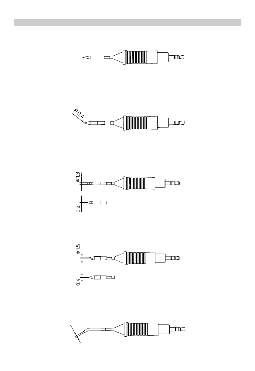
0054460199 RT1 Needle Tip
0054460299 RT2 Fine Point Tip R 0.020” (0,4mm)
0054460399 RT3 Chisel Tip 0.050 x 0.020” (1,3mm x 0,4mm)
0054460599 RT5 Chisel Tip 30° bent 0.030” x 0.020” (0,8mm x 0,4mm)
0054460499 RT4 Chisel Tip 0.060” x 0.020” (1,5mm x 0,4mm)
Page 15

113
3
RReeppllaacceemmeenntt PPaarrttss aanndd AAcccceessssoorriieess
RReeppllaacceemmeenntt PPaarrttss aanndd AAcccceessssoorriiees
s
KKEEYY NNOO.. PPAARRTT NNOO.. DDEESSCCRRIIPPTTIIOON
N
Shown in diagram 0051514599 WMRH Tool Holder for WMRP Soldering Iron
5,6 0052917199 WMRP Pencil, No Tips
4 0052241999 Sponge
For RT series tips see pages 3,4.
SSoollddeerriinngg TTiipps
s
0054460699 RT6 Round Tip 0.050” x 45° (1,2mm x 45°)
0054460799 RT7 Knife Tip 0.090” x 45° (2,2mm x 45°)
Page 16

114
4
TTeecchhnniiccaall SSppeecciiffiiccaattiioonns
s
TTeecchhnniiccaall DDaatta
a
Supply Voltage: 24 VAC
Power Rating: 80 W (2 x 40 W)
Heat Up Time: 3 - 5 sec. (approx.) from ambient to 750ºF (399ºC)
Max. Temp.: 850ºF (450ºC)
Min. Temp.: 200ºF (100ºC)
Tool Cord: Silicone rubber, burn resistant
Connector: Polarized, 6 pin locking
Tip Type: RTW series
Tool Weight: 1.5 ounces without cord
1. Stand / Tool Holder
2. Tip Cleaning Sponge
3. Desoldering Tip Cartridge with Molded Grips
4. Hand Piece
5. Connector / Plug
WWMMRRTTTTwweeeezzeerrss aanndd SSttaannd
d
Page 17

115
5
Thank you for placing your trust in our company by
purchasing the Weller WMRT Micro Tweezer. The
ergonomic anti-static design, selection of desoldering
tweezer tips, and 80 watts of power, provide Weller
superior performance, versatility, and quality.
11.. CCaauuttiioonnss // WWaarrnniinnggss !
!
Please read these Operating Instructions and the
attached Safety Information carefully prior to initial
operation. Failure to observe the safety warnings may
result in accident, injury, or risk to health.
The manufacturer shall not be liable for damage resulting from misuse or unauthorized alterations of the
equipment.
Warning: This product, when used for soldering and
similar applications, produces chemicals known to the
State of California to cause cancer and birth defects or
other reproductive harm.
SSaaffeettyy IInnffoorrmmaattiioon
n
● Always place the WMRT tweezer in the original
holder.
● Remove all inflammable objects from the
proximity of the hot desoldering tool.
● Use suitable protective clothing. There is a risk of
burns associated with molten solder.
● Never leave the hot WMRT tweezer unattended.
● Never work on electrically live circuits or
components.
● Always wear eye protection when working with
soldering and desoldering applications.
22.. DDeessccrriippttiioon
n
The Weller WMRT Tweezers are designed for rework and
repair of precision SMT electronic devices. The desoldering tip set can be quickly and easily changed without the use of tools. The tips are pre-aligned and additional alignment is not required. The integrated (2 X 40
W) heating elements ensure that the desoldering tip
temperature is reached very quickly and controlled precisely. The desoldering tweezers are switched off automatically when placed in the WMRTH tool holder.
The Weller WMRT Tweezers may only be used with the
WD1M or WD2M series power units.
33.. PPllaacciinngg iinnttoo OOppeerraattiioon
n
Place the desoldering tweezers ( 4 ) in the tool holder
and ensure that the hand piece is correctly seated in
the stand ( 1 ). Move all combustible objects away
from the tweezers and the work area. Insert the connector ( 5 ) into the power supply receptacle and lock it
by turning clockwise. Turn the station’s power switch
“On” and set the desired temperature. When the tips
have reached the set temperature, tin both tweezer tips
with solder.
44.. OOppeerraattiinngg IInnffoorrmmaattiioon
n
CChhaannggiinngg tthhee DDeeoollddeerriinngg TTiipps
s
CCaauuttiioonn,, rriisskk ooff bbuurrnnss!
!
Desoldering tips must only be changed when cool. The
tip change does not require tools. The desoldering tip
cartridge is inserted into the front of the hand piece ( 4
). The 5-pin mini-plug on the back of the tip cartridge is
polarized for correct alignment with the hand piece. The
top of the tip cartridge is printed with L (Left) and R
(Right) indicators for proper orientation. The indicators
align with L and R indicators printed on the hand piece.
The tip cartridge ( 3 ) can be removed from the hand
piece by grasping the molded grips and pulling outward
to release.
IImmppoorrttaanntt:
:
Always ensure that the desoldering tip is properly seated.
When installing a new desoldering tip cartridge, ensure
that the cartridge is inserted completely against the
stop in a single motion. Operation with a desoldering tip
that is not completely inserted can cause the tip cartridge to malfunction.
During initial heat up, tin the tips with solder. This
removes oxidation and contamination on the desoldering tips. Before placing the tool in the holder, always
ensure that the desoldering tips are well tinned. Use of
an aggressive flux will possibly shorten tip life.
Always keep the cleaning sponge ( 2 ) damp. Use only
distilled or de-ionized water.
In addition to the informaton included in this manual,
please see the safety manual and the instructions for
the applicable power unit.
SSuubbjjeecctt ttoo tteecchhnniiccaall cchhaannggee wwiitthhoouutt nnoottiiccee!
!
EEnngglliisshh
Page 18
116
6
DDeessoollddeerriinngg TTiipps
s
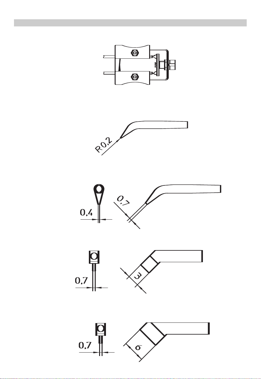
WMRT Tip Cartridge
0054465199 RTW1 Tip Set 0,2 mm (.008”), 45°
0054465299 RTW2 Tip Set 0,7 x 0,4 mm (.028” x .016”), 45°
0054465399 RTW3 Tip Set 3 x 0,7 mm (.118” x .028”), 45°
0054465499 RTW4 Tip Set 6 x 0,7 mm (.236” x .028”), 45°
Page 19

117
7
RReeppllaacceemmeenntt PPaarrttss aanndd AAcccceessssoorriiees
s
KKEEYY NNOO.. PPAARRTT NNOO.. DDEESSCCRRIIPPTTIIOON
N
1,2 0051514699 WMRTH Tool Holder / Stand
2 0052241999 Sponge
3,4,5 0051317299 WMRT Micro Tweezers with RTW2 Tip Set
1,2,3,4,5 0051317399 WMRT Micro Tweezers with WMRTH Stand and RTW2 Tip Set
*For Desoldering Tip Cartridges see page 3.
RReeppllaacceemmeenntt PPaarrttss aanndd AAcccceessssoorriiees
s
Page 20

118
8
WD2M Circuit Diagram
E
nglish
Page 21

119
9
English
WD2M Exploded View
Page 22

wwwwww..ccooooppeerrhhaannddttoooollss..ccoom
m
005 XX XXX XX / 03.06 © 2006 Cooper Industries
Weller is a registered Trademark and registered Design of Cooper Industries, Inc.
UU..SS MMaaiilliinngg AAddddrreessss:
:
CCooooppeerr HHaanndd TToooolls
s
P.O. Box 728
Apex, NC 27502-0728
UU..SS SShhiippppiinngg AAddddrreessss:
:
1000 Lufkin Road
Apex, N.C. 27539
Tel: (919) 387-0099
Fax: (919) 387-2379
For inquiries concerning Technical /
Customer Service please call:
(800) 476-3030 Ext. 1
CCaannaaddaa SShhiippppiinngg AAddddrreessss:
:
CCooooppeerr TToooolls
s
164 Innisfil Street
Barrie, Ontario
Canada L4N 3B7
Attn: Repairs
Fax: 1-800-403-TOOL (8665)
Phone: 705-728-5564 Ext. 2026
 Loading...