

Page 1
®
Endo Menu
Service Manual
Proximal
Video
Camera
PC-10
(Model 65170)
PC-20
(Model 65180)
Operating
Manual
Page 2

Thank you for your purchase of a Welch Allyn VideoPath®Proximal
Video Camera. The operating and maintenance instructions found in this manual
should be followed to ensure many years of reliable service. Please read these
instructions thoroughly before attempting to use your new VideoPath
®
Proximal Video
Camera. It is imperative that instruction manuals for associated equipment, including
the VLX-10 and VLX-20 Light Sources, be read and understood in detail.
WARNING: The user of this equipment should be thoroughly trained in the
medical procedures appropriate to the equipment. Furthermore, time should
be taken to read and understand these instructions before performing any
procedures. Instructions for other equipment used in conjunction with any
VideoPath Proximal Video Camera (e.g. light sources) should also be read
and understood. Failure to do so may result in injury to the patient and/or
damage to the instrument.
While this manual describes the recommended protocol for inspecting and
operating the equipment, it does not outline procedural techniques.
CAUTION: Federal (USA) law restricts this device to sale by/to or on the
order of a physician or other appropriately licensed medical professional.
ii
PC-10/20 VideoPath®Proximal Video Camera
Page 3

Table of Contents
Conventions ..........................................................................2
Symbols.............................................................................2
Specifications........................................................................3
Components..........................................................................4
Nomenclature and Function................................................6
VideoPath Proximal Video Camera.......................................6
Light Source – Front View ....................................................7
Light Source – Back View.....................................................8
Preparation and Inspection for Use ...................................9
Operations ..........................................................................10
Cleaning and Disinfection ..................................................14
Instrument Storage.............................................................15
Servicing ..............................................................................16
Troubleshooting ..................................................................17
®
1
Page 4
Conventions
Warning aler ts the user to possible serious injur y, death or other adverse
reaction associated with the use or misuse of the device.
Caution indicates a potentially hazardous situation which, if not avoided,
may result in minor or moderate injury. It also alerts against unsafe
practices.
NOTE
provides supplemental information to the text and indicates a
potentially hazardous situation which, if not avoided, may result
in property damage. Additionally, it highlights important information on the use of the equipment.
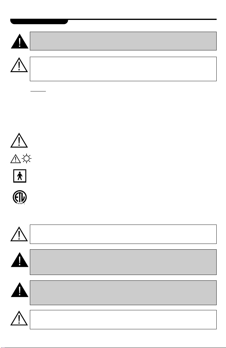
Symbols
Attention: Consult Operator’s Manual for additional information.
Caution: High-intensity light.
Type BF equipment
TYPE BF
IPX7
2
Listed Product - ETL Laboratories
IPX7 Protected against the effects of immersion
Caution: Surface temperatures on patient-contacting probes are likely to
exceed 41°C
Warning: Before using, check outer por tions of the endoscope for
unintended rough surfaces, sharp edges, or protrusions which may cause
a safety hazard
Warning: The illumination fiber bundle used with this system must provide
electrical isolation between patient-contacting probes and the VideoPath®
Proximal Video Camera (no grounding shield or braid)
Caution: The Proximal Video Camera is to be connected to equipment
listed to IEC 601-1 and in compliance with IEC 601-2-18
PC-10/20 VideoPath®Proximal Video Camera
Page 5

Specifications
VideoPath®Proximal Video Camera
Feature PC-10 Control PC-20 with Function
(Model #65170) Control (Model #65180)
Pixels 380,000 380,000
CCD Size 1/2 inch 1/2 inch
Lines of Resolution Greater than 470 lines Greater than 470 lines
Signal System NTSC Color System NTSC Color System
White Balance Control Included Included
Minimum Illumination 4.5 lux at f1.2 4.5 lux at f1.2
Available Video Standard and Zoom Standard and Zoom
Adapters C-mount couplers C-mount couplers
Function Control None F
Switches
Operating Temperature +10°C to +40°C +10° C to +40°C
(50°F to 104°F) (50°F to 104°F)
Relative Humidity 30-75% 30-75%
Safety Approvals UL 2601-1, IEC 601-2-18 UL 2601-1, IEC 601-2-18
®
reeze, Copy, Video
3
Page 6
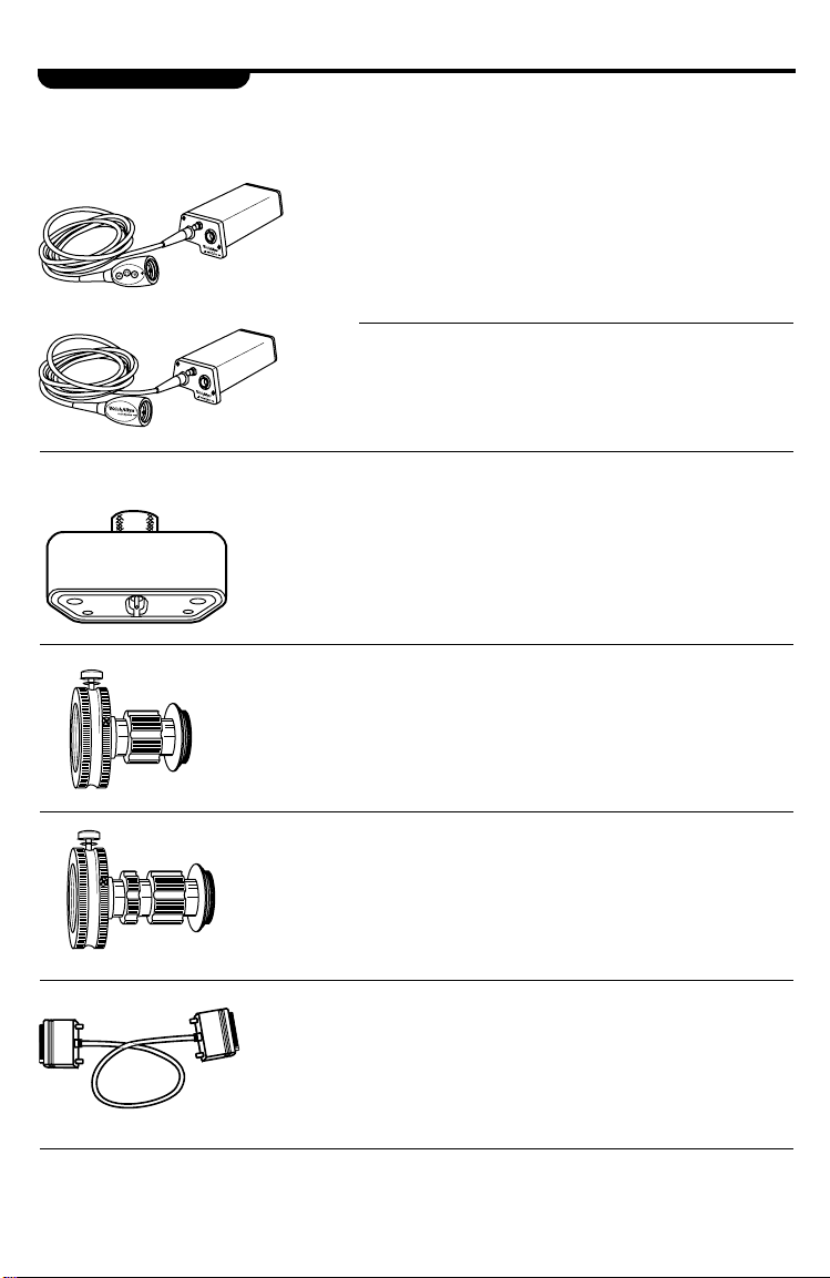
Components
VideoPath®Proximal Video Camera Set Includes:
65180 PC-20 Video Camera with Cable and
Function Controls
or
65170 PC-10 Video Camera with Cable
Optional Accessories
31028 Soaking Cap
65152 Standard C-mount Video Coupler
65153 Zoom Eyepiece Coupler
65158 RS-232 Communication Cable
4
PC-10/20 VideoPath®Proximal Video Camera
Page 7

Components(Cont’d.)
VLX-10 and VLX-20 Light Sources Include:
40500 Light Source or 45500
45510 Water Bottle
761076-0 Power Cord
POWER AIR
LAMP
IGNITION
STANDBY
LAMP
PICTURE
SERVICE
BRIGHTNESS
!
45512 S-Video Cable
45520 Cleaning/Disinfection Bottle
®
5
Page 8

Nomenclature and Function
VideoPath®Proximal Video Camera
C-mount Video Coupler
2. Function
Control Switches
(Model 65180)
Camera Head Contains:
Name Function
1. Imaging CCD Connects to the endoscope
eyepiece via the C-mount
video coupler.
2. Function Control Controls the peripheral
Switches video component such
(Model 65180)
as the video printer.
3. Electrical Contacts
1. Imaging CCD
6. White Balance
Switch
5. Light Guide Input Port
4. Light Guides
Light Guide Connector Contains:
Name Function
3. Electrical Contacts Provide power to the VideoPath Proximal Video
Camera and provides the pathway for video signal
input into the light source.
4. Light Guides Couple to lamps in light source to provide
illumination.
5. Light Guide Input Port Input port for the endoscope light guide connector.
6. White Balance Switch Used to white balance the camera to properly match
the endoscope optical system.
6
PC-10/20 VideoPath®Proximal Video Camera
Page 9

Nomenclature and Function(Cont’d.)
Light Source – Front View
5. Endoscope
Connector
Port
3. Lamp Ignition
4. Lamp Standby
Indicator
1. Main Power Switch
POWER AIR
2
LAMP
IGNITION
STANDBY
LAMP
PICTURE
SERVICE
BRIGHTNESS
7. Picture Brightness
Control
!
8. Air
output
port
2. Air Pump Switch
6. Water Bottle
Name Function
1. Main Power Switch Primary power control for the light source. If not
activated, the VideoPath Proximal Video Camera
as well as other controls will not function.
2. Air Pump Switch Air pump should not be used with the VideoPath
Proximal Video Camera.
3. Lamp Ignition Activates the lamps when the switch is depressed
and the main power switch is on.
4. Lamp Standby Indicator When the LED blinks, lamps cannot be ignited
even if the lamp ignition is depressed.
5. Endoscope Connector Port Accepts VideoPath connector terminal to transmit
light and electrical signal through the VideoPath.
6. Water Bottle Should not be used with the VideoPath Proximal
Video Camera.
7. Picture Brightness Control Since the VideoPath Proximal Video Camera
contains an electronic shuttering system to control
the illumination level automatically, the picture
brightness control is not functional when the
VideoPath Proximal Video Camera is utilized
with the light source.
8. Air Output Port Air pump should not be used with the VideoPath
Proximal Video Camera.
®
7
Page 10

Nomenclature and Function(Cont’d.)
Light Source – Back View
4. Fans
9. Aux(illiary)
Port
2. S-Video
Outputs
3. Composite
Video
6. Earth
Ground
Terminal
Connector
5. Fuse
Drawer
8. RS-232 Communication
Connector Port
Outputs
7. Equipotentiality
Terminal Connector
Name Function
1. Power Supply Cord Couples with the power cord, which should be
Receptacle plugged into a 110-120 VAC hospital grade
2. S-Video Outputs Outputs S-Video or Y/C, 4 position Mini-DIN.
3. Composite Video Outputs Outputs NTSC (composite video), BNC connector.
4. Fans Pulls room air into the light source for forced air
5. Fuse Drawer Opens for replacement of main fuse.
6. Earth Ground Terminal Provides a terminal which is connected to earth
Connector ground through the VLX-20 line cord (1/4-36
7. Equipotentiality Terminal Accepts ground connector from electrosurgery
Connector equipment to provide a secondary or redundant
8. RS-232 Communication Communication port for use with video printers
Connector Port
9. Aux(illiary) Port No function. Future capability.
1. Power Supply
Cord Receptacle
outlet.
cooling.
UNS-2A thread).
ground path.
8
PC-10/20 VideoPath®Proximal Video Camera
Page 11

Preparation and Inspection for Use
Prior To Initial Use
Before preparation and set-up of this equipment, check all components received
against the list of components (see Components section) to verify a complete set.
If parts are missing, please notify Welch Allyn. Review the nomenclature, set-up,
operations and cleaning sections to become familiar with the equipment.
Specifically inspect:
VideoPath®Proximal Video Camera
Camera Head – for any cracks, dents, scratches and debris.
Camera head cable – for any dents, tears or cracks.
Light guide connector – for any cracks, dents, scratches and debris.
Light Source
Cabinet – for any dents, scratches or other abnormalities.
®
9
Page 12
Operations
The methods and techniques of endoscopy are well-defined and documented.
Endoscopy training seminars and preceptor programs are also in existence worldwide. No attempt is made in this manual to outline any medical procedures. Before
beginning a procedure, the physician should be familiar with it and all possible
relative contraindications.
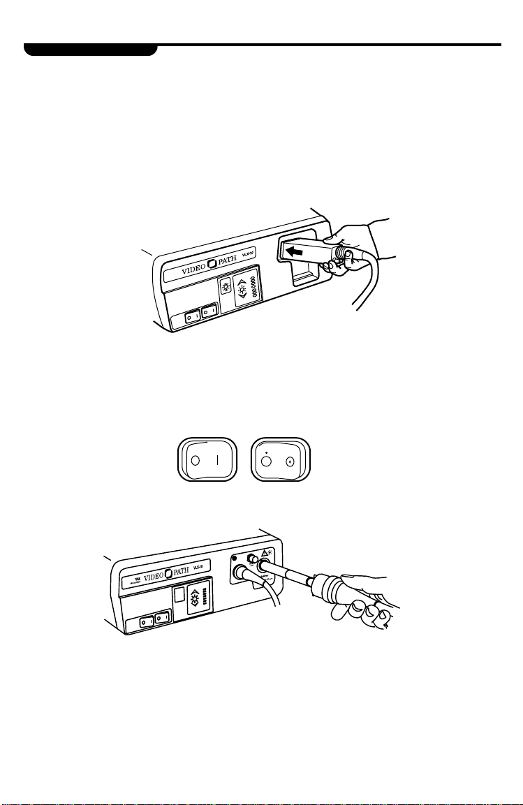
1. Plug the VideoPath
scope connector port of the light source. The Video Camera connector terminal
should fully engage and “click” into place.
2. Activate the Power switch on the front panel. The green Lamp Ignition/Stand-By
light will blink for approximately 11 seconds. Once the LED stops blinking, the
lamps are ready to be ignited.
®
Proximal Video Camera connector terminal into the endo-
LAMP
IGNITION
PICTURE
BRIGHTNESS
LAMP
SERVICE
POWER
AIR
3. Insert the endoscope light guide cable into the light guide post receptacle.
10
PC-10/20 VideoPath®Proximal Video Camera
Page 13

Operations(Cont’d.)
4. Press the Lamp Ignition Switch. The lamps will ignite and the Lamp Ignition/
Standby light will go out. The lamps require 11 seconds to warm up. This length
of time will be indicated by the center LED of the Picture Brightness Indicator,
which blinks until the lamps are fully warmed up, and the system is ready for use.
2
LAMP
IGNITION
POWER AIR
NOTE
: If the Light Source is powered up without
STANDBY
LAMP
PICTURE
SERVICE
BRIGHTNESS
having the VideoPath Proximal Video
Camera attached, the Lamp Ignition
Standby LED will remain blinking and
lamp ignition cannot occur.
WARNING: Once lamps have been lit, do not remove the instrument
from the light source without turning the main power switch off or putting
the lamps on Stand-By by pressing the Lamp Ignition switch. If the VideoPath Proximal Video Camera is removed from the light source, avoid
looking directly into the intense light provided by the light source to
prevent damage to your eyes.
!
Standby
Light
LAMP
IGNITION
LAMP
SERVICE
PICTURE
BRIGHTNESS
5. Connect the Video Coupler to the VideoPath Proximal Video Camera head.
It is important that all lens surfaces are clean and dr y prior to making these
connections.
®
11
Page 14

Operations(Cont’d.)
6. Connect Video Coupler to the eyepiece of
the endoscope. Secure coupler/eyepiece
connection by tightening the thumbscrew
on the coupler.
White Balance Button
8. After white balancing is completed, focus the image
by adjusting the focusing ring on the video coupler.
7. White balance the VideoPath Proximal Video
Camera by aiming the distal tip of the endoscope at a white surface at a distance of one
to two inches. Momentarly depress the white
balance button on the Proximal Video Camera
light source connector. Continue aiming the
endoscope at the white surface until the image
flickers. Once the image flickers, the system
has been properly white balanced.
Thumb Screw
Focusing Ring
9. After the image has been properly focused, it may be necessar y to further adjust
the color. The VideoPath Proximal Video Camera has been preset at the factory
for optimal picture quality and performance. Monitors can vary and therefore may
require some fine tuning. This can be accomplished by using the controls on the
monitor.
In some cases, it may be necessary to reduce the moire effect. Moire is a phenomenon caused by an interference pixel pattern between a fiberscope and a
CCD imager, and can be controlled by either slightly defocusing the image or
by rotating the video coupler with respect to the eyepiece of the fiberscope.
The system is now functional. Illumination level is controlled automatically by an
electronic shuttering system built into the VideoPath.
12
PC-10/20 VideoPath®Proximal Video Camera
Page 15

Operations(Cont’d.)
PC-20 (Model 65180):
Function Control Switches – The function control switches can be used to control
a peripheral video printer. The RS-232 cable must be attached from the light source
(Model VLX-20) to the video printer. The controls are as follows:
F - Freezes the image
C - Prints the image
V - Returns the system to a live video image
By utilizing these switches, the image may be captured and printed for later
observation.
Electrosurgery
The user must read and understand all the instructions in the operating manuals supplied with the electrosurgical generator and associated accessories. All electrosurgical
equipment must be thoroughly inspected prior to use. Only the user can determine if
the condition of the electrosurgical generator and accessories is correct and safe for
clinical use. The active portion of the electrosurgical accessory should always be
clearly visualized before applying electrical energy to the instrument.
Caution: The chassis of the high frequency surgical equipment, if accessible, should be connected to the Equipotentiality Terminal of the VLX-20 Light
Source to eliminate the potential of RF voltage potential between the two
devices during electrosurgery.
1. The recurring peak voltage of the high frequency surgical equipment used should
not exceed 300 Volts in any mode of operation.
2. Avoid the use of high frequency endoscopically-used accessories in the presence of
flammable anesthetics or explosive gas concentrations.
®
13
Page 16

Cleaning and Disinfection
Immediately after the endoscope is removed from the patient, put the lamps on
stand-by by pressing the lamp ignition/standby switch. This will help maximize
lamp life. Next, disconnect the video coupler from the eyepiece of the endoscope.
The VideoPath Proximal Video Camera system and all video couplers should be
properly cleaned. Any debris should be wiped from the coupler, camera head and
cable with a soft lint-free cloth moistened with mild soap and water. An enzymatic
detergent may also be used. See the list below for compatible detergents. (Follow
the dilution instructions provided by the manufacturer.)
Brand Name Source Usage
Endozime The Ruhof Corp.
Klenzyme Calgon Vestal Labs
Enzy-Clean Burnishine Products
Metrizyme Metrex Research Corp.
Enzol J & J Medical
Follow
Manufacturer’s
Instructions
14
PC-10/20 VideoPath®Proximal Video Camera
Page 17

Cleaning and Disinfection(Cont’d.)
Generally, the VideoPath Proximal Video Camera should only require simple cleaning
between procedures. If necessary, the VideoPath Proximal Video Camera may be
soaked in enzymatic cleaner or in glutaraldehyde-based disinfectants. The disinfectants are listed on the following table. It is suggested that the soaking cap be in
place prior to immersing the VideoPath. Follow the manufacturer’s instructions for
the disinfectant being utilized.
Solution Brand Name Source Usage
Cidex (14 Day) (2.4%) J & J Medical
Gluteraldehyde
After soaking, the VideoPath Proximal Video Camera should be rinsed with clean
water and dried prior to storage.
Wavicide-01 (2.5%) Wave Energy
Systems Inc.
Metricide (14 Day) Metrex Research
(2.6%) Corp.
Follow
Manufacturer’s
Instructions
Instrument Storage
Make sure the instrument is clean and dry prior to storage. Do not store the instrument
in an area exposed to extreme temperatures, high humidity or direct sunlight. The
storage area should be clean and dry.
Transport/Storage environment
Ambient temperature -40°C to +50°C (-40°F to 122°F)
Relative humidity 95% max.
®
15
Page 18

Servicing
Prior to returning any instrument for repair to Welch Allyn, the instrument should first
undergo appropriate reprocessing/decontamination procedures for the purpose of
infection control.
1. All instruments requiring repair should be shipped in the original shipping package with appropriate packing along with comments describing the instrument
damage and complaint.
2. A repair/return authorization number, contact name and phone number of the
individual responsible for authorizing repairs, as well as shipping address should
be included.
3. Any accessories potentially related to the damage or complaint also should be
included.
4. Soaking caps (if applicable) also should be returned with the instrument to
check/confirm the integrity of their watertight seal.
NOTE
: Instrument repairs should only be performed by an authorized
Welch Allyn service facility. Welch Allyn assumes no liability
for any patient/user injury, instrument damage or malfunction,
or reprocessing failure due to repairs made by unauthorized
personnel.
Customer Service Telephone Assistance: 1-800-535-6663
Service Information
Customers in North America should return instruments requiring service to the
Welch Allyn Technical Service Department listed below, or to an authorized
Welch Allyn Distributor.
Technical Ser vice Depar tment
Welch Allyn, Inc.
4341 State Street Road
Skaneateles Falls, NY 13153
U.S.A.
Telephone: 800-669-9771
Fax: 315-685-4653
16
PC-10/20 VideoPath®Proximal Video Camera
Page 19

Troubleshooting
Symptom Possible Cause Solution
No image. VideoPath Proximal Advance Video Camera
Video Camera not connector terminal into
properly plugged into light source until it “clicks”
light source. into place.
Image is not clear. Video Coupler not Adjust focusing ring on
properly focused. video adapter until the
image is properly focused.
Endoscope not properly Adjust focus on endoscope
focused. until image is clear.
Lenses dirty. Remove VideoPath
Proximal Video Camera
and coupler and wipe all
lenses with cotton swab
and alcohol.
Inadequate illumination. Light source not turned on. Turn power on to light
source.
Endoscope light guide Plug light guide connector
connector not plugged in into light guide por t in the
to light source. VideoPath light guide plug.
Light source not Not plugged into Plug light source into 120V functioning. electrical outlet. grounded outlet.
Lamps burned out. Replace lamps according
to the light source
instruction manual.
Fuse is blown. Replace fuse.
Lamp access plate not Check plate and reinstall
properly reinstalled. properly according to the
light source instruction
manual.
Function Control RS-232 cable not Connect RS-232 cable Switches not operating. connected between light between light source
source and video printer. (VLX-20) and video printer.
®
17
Page 20

Welch Allyn, Inc.
4341 State Street Road
P.O. Box 220
Skaneateles Falls, NY 13153-0220
U.S.A.
Tel.: 800-535-6663 or
315-685-4560
Fax:315-685-3361
Printed in U.S.A. Part # 651725 Rev. A
 Loading...