

Page 1

Service Manual
Atlas Monitor
Atlas Patient Monitor
Welch Allyn
8500 SW Creekside Pl
Beaverton, Oregon 97008
6200-43E Revision D Copyright 2007
Page 2

Part No. Rev. Description ECN# Date Approved
6200-43E A New release of Atlas Service Manual 5-40429 10/99 RS/LP
6200-43E B Updated calibration procedures
Updated performance verification procedures
Updated drawing 620150 Rev B to Rev C
Updated drawing 620201 Rev A to Rev B
Updated drawing 620524 Rev A to Rev B
Added complete repair parts lists.
Added calibration date table
6200-43E C Updated to reflect changes in hardware and software 5-45730 03/03 DK
5-44782 07/02 DK
Drawings and/or illustrations and/or part numbers contained in this
document are for reference purposes only. For current revisions call the
Welch Allyn Customer Service phone number listed in Section 1 page 2.
Service Manual 6200-43E Rev. D Welch Allyn Atlas Monitor i
Page 3

CONTENTS
List of Figures ...................................................................................................................vi
List of Tables .....................................................................................................................ix
Section 1: General Information
About the Atlas Monitor........................................................................................................1
Help Information ...................................................................................................................2
Agency Approvals .................................................................................................................3
Warning, Cautions and Notes................................................................................................3
Product Model Number Structure.........................................................................................5
623xP Main Menu Architecture............................................................................................6
622xP Main Menu Architecture............................................................................................7
621xP Main Menu Architecture............................................................................................8
Atlas System Block Diagram .................................................................................................9
Section 2: Service
Incoming Inspection............................................................................................................ 11
Calibration and Maintenance Schedule..............................................................................12
Setting Date and Time .........................................................................................................14
Pangea Communication Protocol........................................................................................ 14
BP Calibration...................................................................................................................... 14
50mmHg Calibration............................................................................................................17
250mmHg Calibration..........................................................................................................17
Reset (623xx Models Only)..........................................................................................18
CO
2
ET CO
No-Load Battery Voltage Calibration ..................................................................................20
Battery Voltage Calibration..................................................................................................21
Printer Print Adjustment..................................................................................................... 22
Temperature Calibration...................................................................................................... 23
Calibration Date Set............................................................................................................. 24
Explanation of an Atlas Service Screen..............................................................................25
Calibration ..............................................................................................................19
2
Software Upgrade Procedure...............................................................................................27
Down Loading NVRAM Files..............................................................................................28
ii Welch Allyn Atlas Monitor Service Manual 6200-43E Rev. D
Page 4

Section 3: Functional tests and Trouble Shooting
Power on Self Test ...............................................................................................................37
Menu Functional Test..........................................................................................................38
BP Test..................................................................................................................................40
Static Manometer Accuracy Test.........................................................................................41
BP Leak Test ........................................................................................................................42
Over 15 mmHg Test .............................................................................................................42
BP Dump Verification Test ..................................................................................................43
Hardware Fail Safe Tests .....................................................................................................43
ECG/Respiration Test...........................................................................................................44
SpO2 Test..............................................................................................................................45
Temperature Test .................................................................................................................45
CO2 Functional Test.............................................................................................................45
Battery Functional Test........................................................................................................46
Printer Functional Test ........................................................................................................47
Print on Alarm Test..............................................................................................................47
Software/Firmware ..............................................................................................................47
ECG Alarms Test ..................................................................................................................48
Respiration Alarms Test ......................................................................................................50
SpO2 Alarm Test ..................................................................................................................51
Silence Alarm Test...............................................................................................................52
CO2/RESP Test .....................................................................................................................52
Blood Pressure Alarm Test ..................................................................................................53
Trouble Shooting..................................................................................................................56
Section 4: Disassembly and Repair
About Section 4 ...................................................................................................................63
Battery Door Removal..........................................................................................................64
Battery Removal...................................................................................................................64
Rear Housing Removal ........................................................................................................65
Printer Cable and Display Cable Removal ..........................................................................66
Power Supply Ground Wire Removal.................................................................................66
Tie Wrap Removal................................................................................................................67
CPU Removal .......................................................................................................................67
Service Manual 6200-43E Rev. D Welch Allyn Atlas Monitor iii
Page 5

Main PCB Removal.............................................................................................................. 67
Main PCB Side Connector Removal....................................................................................68
Main PCB Hose and Wire Removal..................................................................................... 68
Pump Removal.....................................................................................................................68
Exhaust Removal..........................................................................................................69
CO
2
Pryon PCB Removal.............................................................................................................69
E-Pac Foam Removal (Top). ................................................................................................69
Power Supply Removal. ......................................................................................................70
Power Supply Fuse Location ..............................................................................................70
Fan Removal ........................................................................................................................70
E-Pac Removal (Lower)........................................................................................................71
Deflection PCB Removal...................................................................................................... 71
CRT Removal .......................................................................................................................71
Display PCB Removal.......................................................................................................... 72
Printer Door Button Removal.............................................................................................. 73
Printer Assembly Locking Tab Release. .............................................................................. 73
Printer Positioning Slot Removal........................................................................................74
Printer Assembly Removal.................................................................................................. 74
Printer Lip Assembly. ..........................................................................................................74
Printer Cable Routing. .........................................................................................................75
Appendix A: Theory of Operation
Power Supply Circuits.........................................................................................................77
Model 622 and Model 623...................................................................................................80
On/Off Circuits ....................................................................................................................81
Battery Charger ....................................................................................................................84
NIBP Circuits ......................................................................................................................87
CRT Deflection Board.......................................................................................................... 92
Vertical Amplifier: ...............................................................................................................92
Recorder Electronics............................................................................................................96
Power Supply – 24 Switcher...............................................................................................96
Motor Driver:........................................................................................................................97
Patient Isolated Circuits ......................................................................................................98
Linear Regulators and Filtering – Model 621 .....................................................................99
iv Welch Allyn Atlas Monitor Service Manual 6200-43E Rev. D
Page 6

Linear Regulators and Filtering – Model 622 and 623.....................................................100
A/D Circuits .......................................................................................................................101
A/D Multiplexer.................................................................................................................102
Serial Communication.......................................................................................................103
Signal Isolation ..................................................................................................................104
ECG Circuits.......................................................................................................................104
Impedance Respiration (Model 622/623 only) .................................................................109
SpO2 Circuits .....................................................................................................................110
Appendix B: Repair Parts Lists
621N0 .................................................................................................................................113
621NP .................................................................................................................................116
621S0..................................................................................................................................119
621SP..................................................................................................................................121
622N0 .................................................................................................................................124
622NP .................................................................................................................................127
622S0..................................................................................................................................130
622SP..................................................................................................................................133
623NP .................................................................................................................................136
623SP..................................................................................................................................142
Appendix C: Interconnect Diagram
Interconnect diagram 620396 Rev A.................................................................................145
Appendix D: Atlas Drawings and Electrical Schematics
See List of Figures on page v for individual drawings.....................................................146
Appendix E: Calibration Date Table
Calibration Date Index Table. ............................................................................................187
Appendix F: Serial Number Cut in History. ...............................................211
Appendix G: Atlas Calibration and Functional Test Form........................ 213
Service Manual 6200-43E Rev. D Welch Allyn Atlas Monitor v
Page 7

List of Figures
Figure 1-1. 623xP Main Menu Architecture. ........................................................................6
Figure 1-2. 622xP Main Menu Architecture. ........................................................................7
Figure 1-3. 621xP Main Menu Architecture. ........................................................................8
Figure 1-4. Atlas System Block Diagram ..............................................................................9
Figure 2-1. Example of a new HyperTerminal connection. ...............................................15
Figure 2-2. Choosing COM1 in HyperTerminal..................................................................15
Figure 2-3. HyperTerminal Port Settings. ...........................................................................16
Figure 2-4. Photo of Atlas BP calibration setup. ................................................................17
Figure 2-5. Example of CO2 calibration setup.................................................................... 21
Figure 2-6. Example and Explanation of an Atlas Service Screen ....................................25
Figure 2-7. Pangea prompt in HyperTerminal ....................................................................29
Figure 2-8. Choosing “Send Text File” in HyperTerminal.................................................29
Figure 2-9. Choosing directory where NVRAM files are stored. ....................................... 30
Figure 2-10. Choosing the nvram_cal_init.txt file. ............................................................. 30
Figure 2-11. Pangea screen after opening the nvram_cal_init.txt file. ..............................31
Figure 2-12. Pangea screen after opening the nvram_common.txt file. ............................31
Figure 2-13. Pangea prompt after opening the model# file................................................ 32
Figure 2-14. Pangea screen after loading a language file. ..................................................33
Figure 2-15. Pangea screen after downloading the nvram_printer.txt file. .......................34
Figure 2-16. Pangea screen nvram set serial command. .................................................... 35
Figure A-1. Model 621 DC/DC circuit block diagram. .......................................................77
Figure A-2. On/Off Control Circuits. ..................................................................................78
Figure A-3. Model 621 Buck converter...............................................................................79
Figure A-4. Model 621 linear regulation. ...........................................................................80
Figure A-5. DC/DC circuit diagram.....................................................................................81
Figure A-6. Boost converter and off/on switch. .................................................................82
Figure A-7. Boost converter.................................................................................................83
Figure A-8. Battery charging. ..............................................................................................85
Figure A-9. Linear regulator. ...............................................................................................86
Figure A-10. NIBP PWM A/D converter. ............................................................................86
Figure A-11. PWM timing. ..................................................................................................87
Figure A-12. Primary transducer amplifier.........................................................................89
Figure A-13. Safety transducer amplifier............................................................................90
vi Welch Allyn Atlas Monitor Service Manual 6200-43E Rev. D
Page 8

Figure A-14. Over pressure fault circuit. ............................................................................91
Figure A-15. Pump relay circuit..........................................................................................91
Figure A-16. Ramp generator circuit...................................................................................92
Figure A-17. Vertical amplifier circuit................................................................................93
Figure A-18. Horizontal amplifier grid voltage circuit. .....................................................95
Figure A-19. Video amplifier circuit...................................................................................96
Figure A-20. Recorder power supply circuit. .....................................................................97
Figure A-22. Print head temperature circuit. .....................................................................98
Figure A-23. Patient isolation circuit..................................................................................99
Figure A-24. Model 621 line regulation and filtering. .......................................................99
Figure A-25. Model 622/623 line regulation and filtering...............................................100
Figure A-26. A/D converter circuit. ..................................................................................101
Figure A-27. A/D multiplexer circuit. ..............................................................................102
Figure A-28. Serial communication circuit. .....................................................................104
Figure A-29. Defib protect and RFI filtering circuit. ........................................................105
Figure A-30. Input buffer circuit.......................................................................................105
Figure A-31. Lead select circuit. .......................................................................................106
Figure A-32. Differential amp/slew rate amp circuit. ......................................................107
Figure A-33. Right leg drive circuit. .................................................................................107
Figure A-34. High pass and gain stage circuit. .................................................................108
Figure A-35. Temperature amplifier circuit......................................................................108
Figure A-36. Respiration drive circuit. .............................................................................109
Figure A-37. Respiration diff amp circuit......................................................................... 110
Figure A-38. Gain and filter circuit...................................................................................110
Figure C-1. Atlas Interconnect Diagram............................................................................145
Figure D-1. Atlas model 200 main board..........................................................................147
Figure D-2. Atlas model 200 NIBP electronics. ................................................................148
Figure D-3. Atlas model 200 power supply......................................................................149
Figure D-4. Atlas Power isolation /SpO2 interface........................................................... 150
Figure D-5. Atlas model 200 ECG amp. ............................................................................151
Figure D-6. Atlas ECG A/D interface.................................................................................152
Figure D-7. Atlas CPU subsystem. ....................................................................................153
Figure D-8. Atlas FPGA. ....................................................................................................154
Figure D-9. Atlas 200/210/220 I/O filters. ........................................................................155
Service Manual 6200-43E Rev. D Welch Allyn Atlas Monitor vii
Page 9

Figure D-10. Flash, SDRAM HRESET config word. .........................................................156
Figure D-11. Power PC MP C823 CPU. .............................................................................157
Figure D-12. Power distribution........................................................................................ 158
Figure D-13. Front panel display. .....................................................................................159
Figure D-14. Key board scanner. .......................................................................................160
Figure D-15. Temp/pulse LED drivers. .............................................................................161
Figure D-16. NIBP LED drivers. ........................................................................................162
Figure D-17. SpO2 LED drivers. ........................................................................................163
Figure D-18. CRT deflection board. ..................................................................................164
Figure D-19. Printer electronics. .......................................................................................165
Figure D-20. Model 220 main board. ................................................................................166
Figure D-21. 210/220 NIBP electronics.............................................................................167
Figure D-22. DC/DC power supply....................................................................................168
Figure D-23. Power isolation/SpO2 interface. ..................................................................169
Figure D-24. 210/220 ECG amp.........................................................................................170
Figure D-25. 210/220 ECG A/D interface..........................................................................171
Figure D-26. 210/220 Respiration circuit. ........................................................................172
Figure D-27. 210/220 serial communication. ...................................................................173
Figure D-28. 200/210/220 transformer isolation. .............................................................174
Figure D-29. 200/210/220 ECG patient cable. ..................................................................175
Figure D-30. 200/210/220 power supply sub assy. ..........................................................176
Figure D-31. 220 ETCO2 PCB assembly. ...........................................................................177
Figure D-32. 200/210/220 Power supply. .........................................................................178
Figure D-33. Nonin SpO
Board........................................................................................179
2
Figure D-34. Motor Stepper...............................................................................................180
Figure D-35. Pump Pneumatic. .........................................................................................181
Figure D-36. 200/210/220 ECG cable assembly. ...............................................................182
Figure D-37. CO2 cable assembly. .....................................................................................183
Figure D-38. Nellcor sensor cable assy. ............................................................................ 184
Figure D-39. 200/210/220 Pneumatic sub assy.................................................................185
Figure D-40. 220 CO
cable assy. ......................................................................................186
2
viii Welch Allyn Atlas Monitor Service Manual 6200-43E Rev. D
Page 10

List of Tables
Table 1-1. Operator manual part numbers. ...........................................................................1
Table 2-1. Atlas Packing List. ..............................................................................................11
Table 2-2. Tools Required for Service. ................................................................................13
Table 2-3. Software Revision Table .....................................................................................26
Table 2-4. Files needed to download language(s)...............................................................33
Table 3-1. Transducer pressure table...................................................................................41
Table 3-2 Resistor and temperature reference. ...................................................................45
Table 3-3. Atlas failure trouble shooting.............................................................................56
Table 3-4. Atlas failure trouble shooting.............................................................................57
Table 3-5. Atlas failure trouble shooting.............................................................................58
Table 3-6. Atlas failure trouble shooting.............................................................................59
Table 3-7. Atlas failure trouble shooting.............................................................................60
Table 3-8. Atlas failure trouble shooting.............................................................................61
Table A-1. Temperature coefficient.....................................................................................84
Table B-1. Atlas 621N0 repair parts ..................................................................................113
Table B-2. Atlas 621NP repair parts. .................................................................................116
Table B-3. Atlas 621S0 repair parts...................................................................................119
Table B-4. Atlas 621SP repair parts...................................................................................121
Table B-5. Atlas 622N0 repair parts. .................................................................................124
Table B-6. Atlas 622NP repair parts. .................................................................................127
Table B-7. Atlas 622S0 repair parts...................................................................................130
Table B-8. Atlas 622SP repair parts...................................................................................133
Table B-9. Atlas 622NP repair parts. .................................................................................136
Table B-10. Atlas 623SP repair parts................................................................................. 139
Table B-11. Atlas 623NP repair parts. ...............................................................................142
Table D-1. Atlas drawings revision page...........................................................................146
Table F-1. Changed to a new BP Valve..............................................................................211
Table F-2. Changed E-Pac and Changed to class B power supply. ..................................211
Table F-3. Upgraded printer cable to a cable with foam tape. .........................................211
Table F-4. Upgraded Revision level of CPU from 501 to 502...........................................211
Table F-5. Upgraded Revision level of Nellcor SpO
to 506............................................212
2
Service Manual 6200-43E Rev. D Welch Allyn Atlas Monitor ix
Page 11

x Welch Allyn Atlas Monitor Service Manual 6200-43E Rev. D
Page 12

Page 13
General Information Section 1
About the Atlas Monitor
The Atlas Monitor combines in one unit all the necessary measurements for patients under
anesthesia, for surgical recovery, or bed side monitoring. See Section 1, page 5 for a complete
listing of product models and options.
According to the standards of care for Nurse Anesthetists and Anesthesiologists, all patients
receiving conscious sedation are to be continuously monitored throughout the procedure and
recovery phase by ECG, SpO2, and NIBP. CO2 monitoring is a requirement during gas
anesthesia (when patient is ventilated).
The Atlas combines a CRT to display ECG, CO2, SpO2, and respiration waveforms. It utilizes
LEDs for the other numeric values to maximize visibility and viewing angle. Although not
designed to be a transport product, the monitor has an integral handle and it is small and
light enough at 13 lbs. to be easily moved.
A battery was added to enable the monitor to be used if there is a power outage or to be
unplugged momentarily when moved with the patient from the surgery room to the recovery
room. The battery was not designed to make the Atlas into a transport monitor. The Atlas
monitor should be plugged into AC as much as possible to give you the maximum battery
backup time when there is a power outage. It will maintain unit operation for up to an hour
when power is interrupted if the battery is fully charged.
WARNING: Discharging the battery frequently will shorten the battery
life and will shorten the battery backup time.
IMPORTANT: For a complete description on the function and use of the Atlas, as well as user
safety warnings, cautions, and warranty information, read and understand the Atlas
Operator’s Manual. See the Table 1-1 below for correct Operator’s Manual part #.
Table 1-1. Operator manual part numbers.
Language Part#
English 6200-42E
French 6200-42F
German 6200-42G
Italian 6200-42I
Spanish 6200-42S
Portuguese 6200-42P
Japanese 6200-42J
Chinese 6200-42C
Service Manual 6200-43E Rev. D Welch Allyn Atlas Monitor 1
Page 14

Section 1 General Information
J
J
Help Information
To assure correct operation and performance all service and repairs must be performed by
fully trained and properly equipped personnel, using genuine replacement parts and correct
procedures. Failure to do so will also invalidate the product warranty.
Welch Allyn Inc.
State Street Plant /Corporate Headquarters
4341 State Street Road
Skaneateles Falls, NY 13153-0220, USA
tel: 1-800-535-6663
315-685-4100
fax: 315-685-3361
www.welchallyn.com/medical/support/tech
Welch Allyn GMBH
Zollerstrasse 2-4
72417 Jungingen, Germany
tel: (011) 49-7477-927186
fax: (011) 49-7477-927193
Welch Allyn UK Ltd
St. Georges House
Vernon Gate, Derby
England DE1 1UQ
tel: (011) 44-01332-206208
fax: (011) 44-01332-206209
mob: (011) 44-0467-301814
MD International
11300 N.W. 41st Street
Miami, FL 33178 USA
tel: 305-669-9003
fax: 305-669-1971
Welch Allyn France SARL
814 rue Charles de Gaulle
77100 Mareuil les Meaux
France
tel: ( 011) 33 1.6009.3366
Fax: (011) 33 1 .6009.6797
Welch Allyn Australia Pty
The Metro Centre Unit 5
38-46 South Street
Rydalmere NSW 2116, Australia
Postal address:
PO Box 132
Rydalmere NSW 1701, Australia
tel: (011) 612 9638-3000
fax: (011) 612 9638-3500
Welch Allyn Singapore Ltd
300 Beach Road, #25-08
The Concourse
Singapore 199589, Singapore
tel: (011)
fax: (011)
Welch Allyn Japan K.K.
Bon Marusan 8F, 3-5-1 Kanda
inbo-Cho, Chiyoda-Ku
Tokyo 101-0051
apan
tel: (011) 813-5212-7391
fax: (011) 813-3261-7372
65-291-0882
65-291-5780
China Service Center
Room 708 Central Plaza
No. 277 Huang Pi Bei Rd.
Huang Pi District
Shanghai 200003
China
tel: (011) 86-21-63279631
fax: (011) 86-21-63279632
2 Welch Allyn Atlas Monitor Service Manual 6200-43E Rev. D
Page 15

General Information Section 1
Agency Approvals
ETL Listed
UL2601-1,
CSA C22.2 No. 601.1
IEC 60601-1, AS 3200.1
IEC 60601-1-2
US
The CE mark on this product indicates that it
has been tested to and conforms with the
provisions noted
within the 89/336/ECC
Electromagnetic Compatibility Directive.
Australia EMC Framework Compliance
C
L
D
I
S
E
T
742 27
N344
Warning, Cautions and Notes
All operating and service personnel should be familiar with the general safety information
in this summary. Specific warnings and cautions will also be found throughout the operators manual. Such specific warnings and cautions may not appear here in the summary.
Electrical Shock Hazard
CAUTION
Service Manual 6200-43E Rev. D Welch Allyn Atlas Monitor 3
Page 16
Section 1 General Information
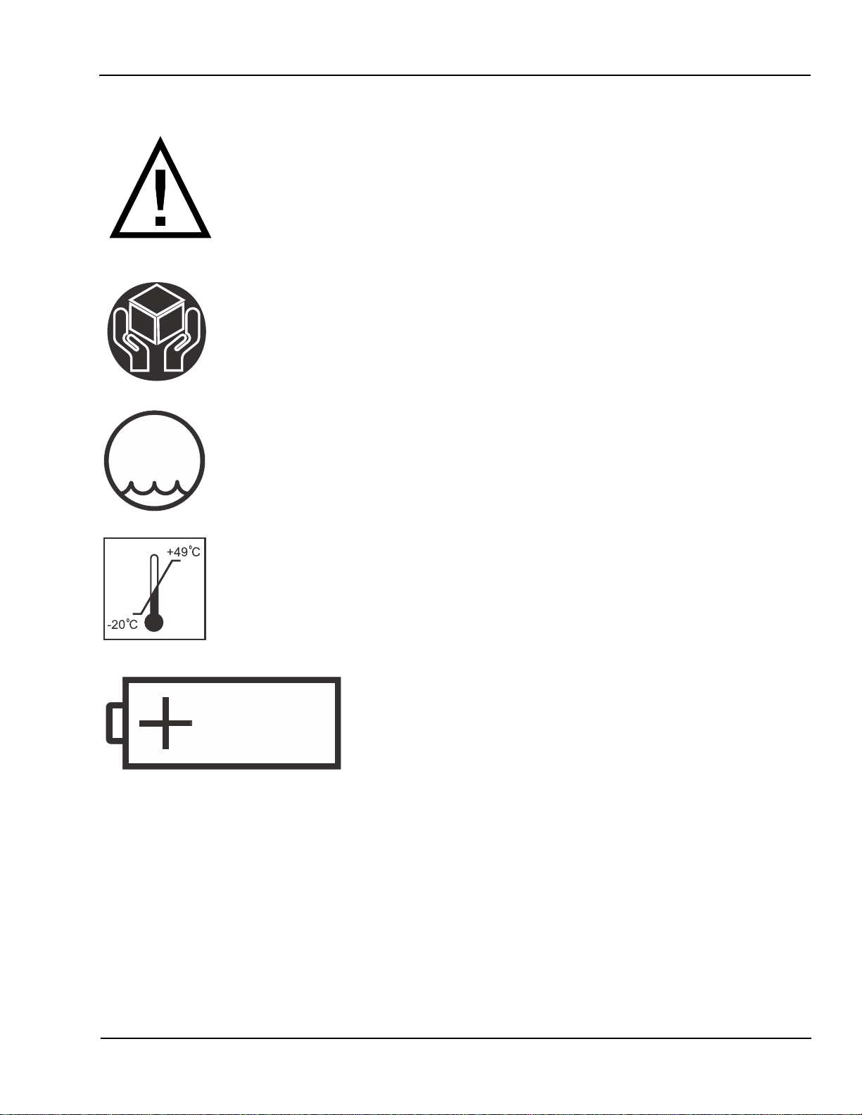
ATTENTION. Consult accompanying document
Handle With Care
Storage Humidity. Refer to technical specifications in operator's
95%
MAX
for more details.
Storage temperature. Refer to technical specifications in operator's
manual for more details.
Lead Acid Battery. For disposal see maintenance
section in opertor's manual
PB
4 Welch Allyn Atlas Monitor Service Manual 6200-43E Rev. D
Page 17

General Information Section 1
Product Model Number Structure
621S0-E1 ECG, Nonin SpO2, NIBP
621SP-E1 ECG, Nonin SpO2, NIBP, Printer
621N0-E1 ECG,Nellcor SpO2,NIBP
621NP-E1 ECG,Nellcor SpO2,NIBP, Printer
622S0-E1 ECG, Nonin SpO2, NIBP, Temp, Respiration, Battery, RS232
622SP-E1 ECG, Nonin SpO2, NIBP, Temp, Respiration, Battery, RS232, Printer
622N0-E1 ECG, Nellcor SpO
, NIBP, Temp, Respiration, Battery, RS232
2
622NP-E1 ECG, Nellcor SpO2, NIBP, Temp, Respiration, Battery, RS232, Printer
623SP-E1 ECG, Nonin SpO2, NIBP, ETCO2, Temp, Respiration, Battery, RS232, Printer
623NP-E1 ECG, Nellcor SpO2, NIBP, ETCO2, Temp, Respiration, Battery, RS232, Printer
Product Structure Meaning:
The first three digits in the product structure sequence designates the model number. The
fourth character in the sequence designates the SpO2. The fifth character in the sequence
designates if it has a printer or not. The first suffix designates the country language when
shipped. The second suffix designates the power cord shipped with the Atlas.
First Three Characters:
Fourth Character: N=Nellcor SpO2, S=Nonin SpO
Model number, 621, 622, 623
2
Fifth Character: P=Printer, 0=No Printer
First Suffix:
E = English, F= French, G= German, I= Italian, S= Spanish, P= Portuguese C =
Chinese,
J= Japanese
Second Suffix:
1 = US, Canada, Japan
2 = European
4 = United Kingdom
6 = Australian
Service Manual 6200-43E Rev. D Welch Allyn Atlas Monitor 5
Page 18
Section 1 General Information
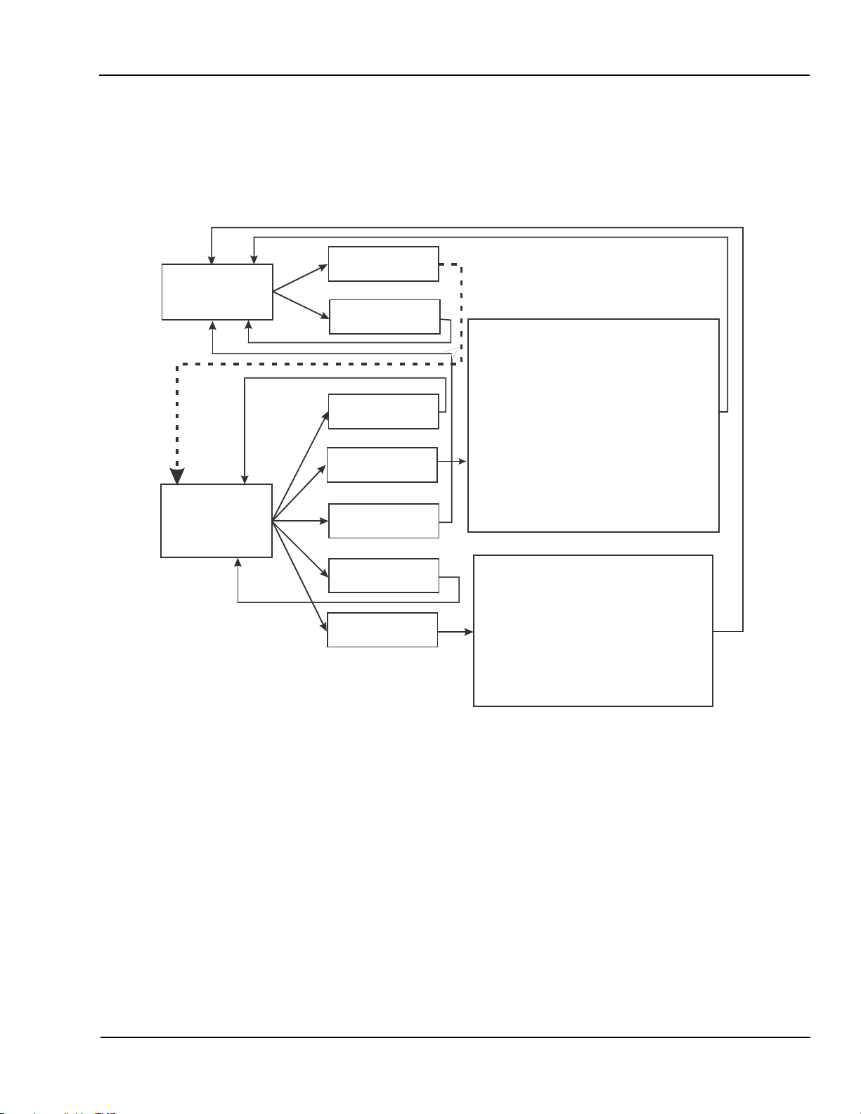
623xP Main Menu Architecture
Figure 1-1. 623xP Main Menu Architecture.
623xP
Date/Time
Wavef orm
screen
Date/Time
Screen
Screen
Trend
Screen
Set date & time
Advanced
Configuration
Co
2
Reset
Save
Settings
Service Mode
Screen
Advanced Configuration Screen
Language
Silence duration
ECG gain
ECG lead set
ECG speed
ECG bandwidth
Initial pressure
MAP
Second trace selection
Temperature units
Respiration speed
units
CO
2
Print on alarm
(only with software Rev.
BB.2.2000 or higher)
Service Mode Screen
Verify manometer
Reset to factory defaults
Battery test
Calibrate Co
CRT test pattern
Printer test pattern (Models 621SPand
LED test
Button test
Display A/D channels *
2
621NP only)
NOTE: The Print on alarm function in Advanced configuration mode screen is only
available with software version BB.2.2000 and higher.
* NOTE: The Display A/D channels function in the Service Mode Screen only allows
you to view system information by pressing the SET button. It does not allow
you to change system settings.
6 Welch Allyn Atlas Monitor Service Manual 6200-43E Rev. D
Page 19
General Information Section 1
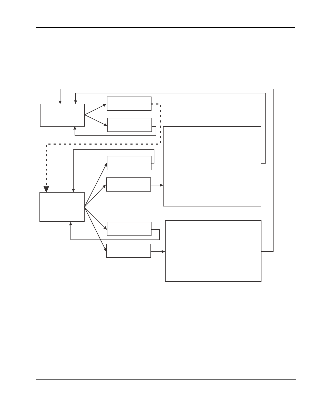
622xP Main Menu Architecture
Figure 1-2. 622xP Main Menu Architecture.
622xP
Date/Time
Waveform
screen
Date/Time
Screen
Screen
Trend
Screen
Set date & time
Advanced
Configuration
Advanced Configuration Screen
Language
Silence duration
ECG gain
ECG lead set
ECG speed
ECG bandwidth
Initial pressure
MAP
Second trace selection
Temperature units
Respiration speed
Print on Alarm
(Only with software Rev.
BB.2.2000 and higher.)
Service Mode Screen
Save
Settings
Service Mode
Screen
Verify manometer
Reset to factory defaults
Battery test
CRT test pattern
Printer test pattern
LED test
Button test
Display A/D channels
(Models 622SP and
622NP only)
*
NOTE: The Print on alarm function in Advanced Configuration Screen is only
available with software version BB.2.2000 and higher.
NOTE: On models 622S0 and 622N0 delete the Print test pattern function in the
Service Mode Screen. Model 622S0 and 622N0 do not come with printers.
* NOTE: The Display A/D channels function in the Service Mode Screen only allows
you to view system information by pressing the SET button. It does not allow
you to change system settings.
Service Manual 6200-43E Rev. D Welch Allyn Atlas Monitor 7
Page 20

Section 1 General Information
621xP Main Menu Architecture
Figure 1-3. 621xP Main Menu Architecture.
621xP
Date/Time
Waveform
screen
Screen
Trend
Screen
Set date & time
Advanced
Configuration
Advanced Configuration Screen
Language
Silence duration
ECG gain
ECG lead set
ECG speed
ECG bandwidth
Initial pressure
MAP
Second trace selection
Print on Alarm
(Only with software Rev.
BB.2.2000 and higher.)
Date/Time
Screen
Service Mode Screen
Save
Settings
Service Mode
Screen
Verify manometer
Reset to factory defaults
CRT test pattern
Printer test pattern
LED test
Button test
Display A/D channels
(Models 621SP and
621NP only)
*
NOTE: The Print on alarm function in Advanced configuration mode screen is only
available with software version BB.2.2000 and higher.
NOTE: On models 621S0 and 621N0 delete the Print test pattern function in the
Service Mode Screen. Model 622S0 and 622N0 do not come with printers.
* NOTE: The Display A/D channels function in the Service Mode Screen only allows
you to view system information by pressing the SET button. It does not allow
you to change system settings.
8 Welch Allyn Atlas Monitor Service Manual 6200-43E Rev. D
Page 21
General Information Section 1
Atlas System Block Diagram
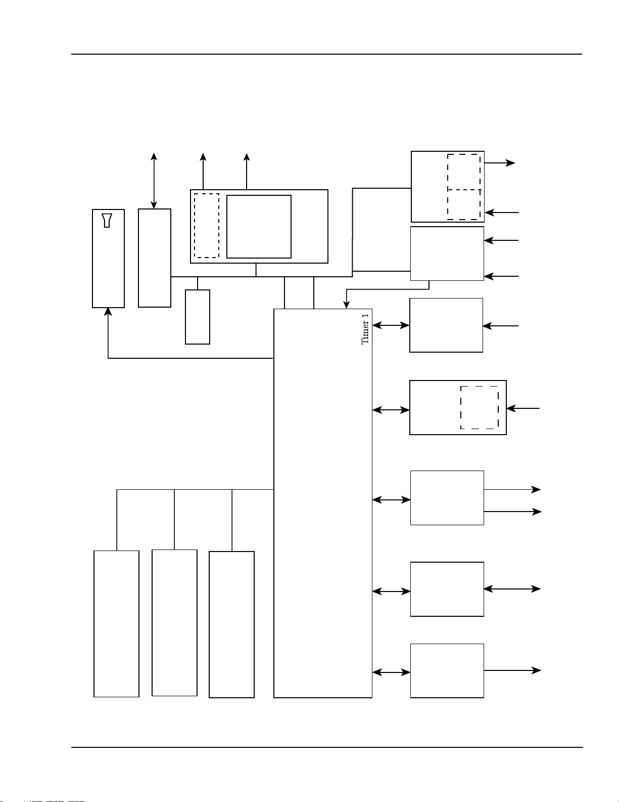
Figure 1-4. Atlas System Block Diagram
15X7
31 LEDs
24
Keys
EKG
X5
Temp
Primary
Sensor
CO2 Sensor
CRT SubSystem
CO2 SubSystem
Motor
Driver Motor
Configuration
EEPROM
Print Head
Clock, Load
AT90A4414
8 bit
Controller
Strobe
SPI
Printer
Subsystem
GPIO
3-wire SPI + nine
chip select
Timer 2
LED
Drivers
Front Panel
Front End
P
W
EKG +
Key
Temp
(Isolated)
Board
PW
NIBP
Front End
5 Volt Video Signals:
H-Sync, V Sync, Video
4M X 16
SDRAM
Local System Bus
Address,Data,Control
512 X 16 Flash
Bus Config.
Register
Motorola CPU
MPC823Z3
GPIO
GPIO
UART-2
UART-1
ON,OFF
ACON,
SYNC
2
TTL
RS-232
Power
Supply
NIBP
Pnuematic
Control
SPO2
Sub-System
(Isolated)
RS-232
Drivers
(Isolated)
Battery
Drivers
Valv e
PumpSPO2
Sensor
Rs-232
Test
AC
Port
Line
TTL
RS-232
Service Manual 6200-43E Rev. D Welch Allyn Atlas Monitor 9
Page 22

Page 23

Service Section 2
Incoming Inspection
NOTE: Use the following guidelines when unpacking the monitor from its shipping carton.
1. Before opening the monitor shipping carton, check for damage.
2. If damage is apparent, stop unpacking the carton and contract the shipping company for
further instructions. If the carton is intact, unpack the monitor.
3. With the monitor out of its carton, check to see that all the items listed on the packing
slip are in the shipping carton. See table 2-1 below.
Table 2-1. Atlas Packing List.
Qty. Description
1 Warranty card
1 Adult Durable 1pc. Cuff
1 Large Adult Durable 1pc. Cuff
1 5ft. Stra ight Hose
1 ECG Patient Cable (Three Lead)
3 ECG Lead Wires
1SpO
1ETCO
1ETCO
1 Nasal Canula 623 only
1Atlas Monitor
1 Detachable Power Cord
1 Printer Paper Roll
1 Operation Manual
1 Skin Tem perature Probe 622/623 only
Sensor/ Finger Clip
2
Water Trap 623 only
2
Scrubber 623 only
2
4. If an item is missing, first check the carton, then check with your receiving department. If necessary
contact Welch Allyn at the address and phone number shown on Section 1.
5. Clean and disinfect by following the instructions printed in the Operator Manual.
NOTE: Perform all functional tests as listed in Section 3 before and after servicing.
Operate the Atlas to verify the customer complaint before making any changes to the unit.
Call the customer if the complaint is unclear.
If the unit has caused or is suspected of having caused an injury of any type: DO NOT
DISASSEMBLE OR REPAIR THE UNIT IN ANY WAY. Contact Welch Allyn Customer
Service immediately.
Service Manual 6200-43E Rev. D Welch Allyn Atlas Monitor 11
Page 24

Section 2 Service
Calibration and Maintenance Schedule
The Atlas Monitor must be serviced by authorized Welch Allyn personnel or agents at 6
month intervals. Maintenance requirements are specified for 6 month and 12 month service
intervals. The monthly CO2 Reset operation can be performed by the user.
Service Interval Maintenance Requirements
Every 6 months: CO2 Calibration
Every 12 months: BP calibration, CO2 reset, battery voltage calibration,
printer adjustment,and temperature calibration.
Complete functional test
12 Welch Allyn Atlas Monitor Service Manual 6200-43E Rev. D
Page 25

Service Section 2
Table 2-2. Tools Required for Service.
Description Part# Company
100cc Test Volume T-112189 Welch All
500cc Test Volume T-112854 Welch All
T-10 TORX screwdriver XTD-10 Xcelite brand
7/16" dee
S
queeze Bulb and Valve 5088-01 Welch Allyn
Calibrated Manometer (0-10PSIG) Di
Bio-Tek (NIBP TESTER) BP Pum
Pneumatic Tubin
Pneumatic Tubin
"Y" Fittin
"T" Fittin
Nonin Patient Simulator 8000S Nonin
Nonin Cable 5200-52 Nonin
Calibrated Thermome ter for 90F to 115F ran
LG, Adult Cuff/Ba
Nellcor Patient Simulator For atlas with "MP
204/205 S
Nellcor Patient Simulator "MP 506 PCB ONLY " SRC-MAX Nellcor
Nellcor Sensor Cable "Purple Connectors" will work
on all Atlas units with 204/205/506 S
Nellcor Sensor Cable "Gray Connectors" "For Atlas
units with MP 204/205 S
ECG Simulator with Im
ECG Patient Cable (5 lead AHA) 6200-02 Welch All
ECG Patient Cable (5 lead IEC) 6200-04 Welch All
ECG leads, 5 Lead (IEC) 6200-08 Welch All
ECG leads, 5 Lead AHA 6200-06 Welch All
Certified Gas "10% CO2,10% O2, balance N2"
ETCO2 Water Tra
ETCO2 Scrubber 6200-21 Welch All
ETCO2 Adult Nasal Sam
Surface Sensor, Tem
Atlas Re
Printer Pa
Digital Multimeter with 10mV accuracy on a 10V
scale; 10A Ran
Ad
Battery cable assembly 620174-1 Welch Allyn
Atlas interface cable to PC 6200-60 Welch All
PC with Windows 95 and above and with
HyperTerminal serial port software
1/4" Mono Phono Jack
1000 Ohm
1200 Ohm
1350 Ohm
1540 Ohm
1870 Ohm
p socket for Temperature Port nut Generic 1/4" drive
gimano 1000 Netech
p Bio-Tek
g 5200-19 Welch Allyn
g (coiled) 5200-19M Welch Allyn
g "Optional" 9586TPK4 Welch Allyn
g (3) 9858TPK4 Welch Allyn
ge 1002-3FC ERTCO
g 5200-02 Welch Allyn
pO2 PCB ONLY " SRC-2 Nellcor
pO2 PCB DEC-8 Nellcor
pO2 PCB only"EC-8 Nellcor
pedance Respiration 214B DNI Nevada
0304724SRBD Scott Medical Products
p (package of 5) 6200-20 Welch Allyn
ple Line 6200-22 Welch Allyn
perature 6200-15 Welch Allyn
pair and Calibration Software 620538 Welch Allyn
per - Case 6200-40 Welch Allyn
ge
justable DC power supply 5A @ 7V
Part of Windows 95 &
above
precision resistor 1%
precision resistor 1%
precision resistor 1%
precision resistor 1%
precision resistor 1%
yn
yn
yn
yn
yn
yn
yn
yn
Service Manual 6200-43E Rev. D Welch Allyn Atlas Monitor 13
Page 26

Section 2 Service
Setting Date and Time
NOTE: Check date and time before doing any calibration. Set date and time if incorrect. Set
time and date as follows;
1. Turn Atlas on.
2. Press CLOCK button next to power on button to check date and time. Use the far right
SELECT button to scroll. Highlight the date or time that needs changed.
3. Press the SET button to adjust date and time.
4. Press CLOCK button to exit.
Pangea Communication Protocol
The Pangea Communication Protocol allows interaction of the Atlas with the computer
through the serial interface port. A prompt is emitted at the computer screen when the
instrument powers up and is ready to accept commands. The prompt is Pangea>. A prompt
is emitted after the completion of each pangea command. Pangea commands are case sensitive. They are in English only.
BP Calibration
Required material.
1. 500cc vessel 4. Calibrated digital manometer
2. Squeeze bulb with one-way valve 5. Tubing and T fittings
3. PC with HyperTerminal 6. Serial cable
NOTE: To start HyperTerminal you must have Windows7 95 or higher installed on your
computer.
1. From the Windows main screen follow the following sequence:
Start !Programs ! Accessories ! Communication ! HyperTerminal
2. HyperTerminal setting are:
9600 baud rate, 8 bit word, 1 stop bit
no parity, no flow control
ANSI character set
14 Welch Allyn Atlas Monitor Service Manual 6200-43E Rev. D
Page 27
Service Section 2
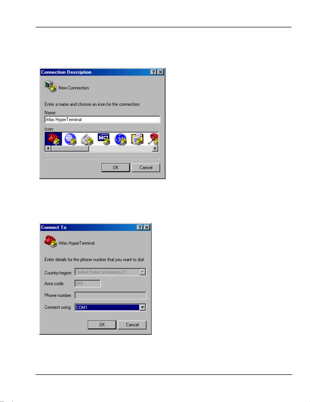
3. When you open HyperTerminal you will see a screen similar to the example in Figure
2-1. You will be prompted for a connection description. Choose any name. After you
type in a name click OK.
Figure 2-1. Example of a new HyperTerminal connection.
4. The next window you will see will be the window as shown in Figure 2-2. Click on
Connect using then click on COM1.
Figure 2-2. Choosing COM1 in HyperTerminal.
Service Manual 6200-43E Rev. D Welch Allyn Atlas Monitor 15
Page 28
Section 2 Service
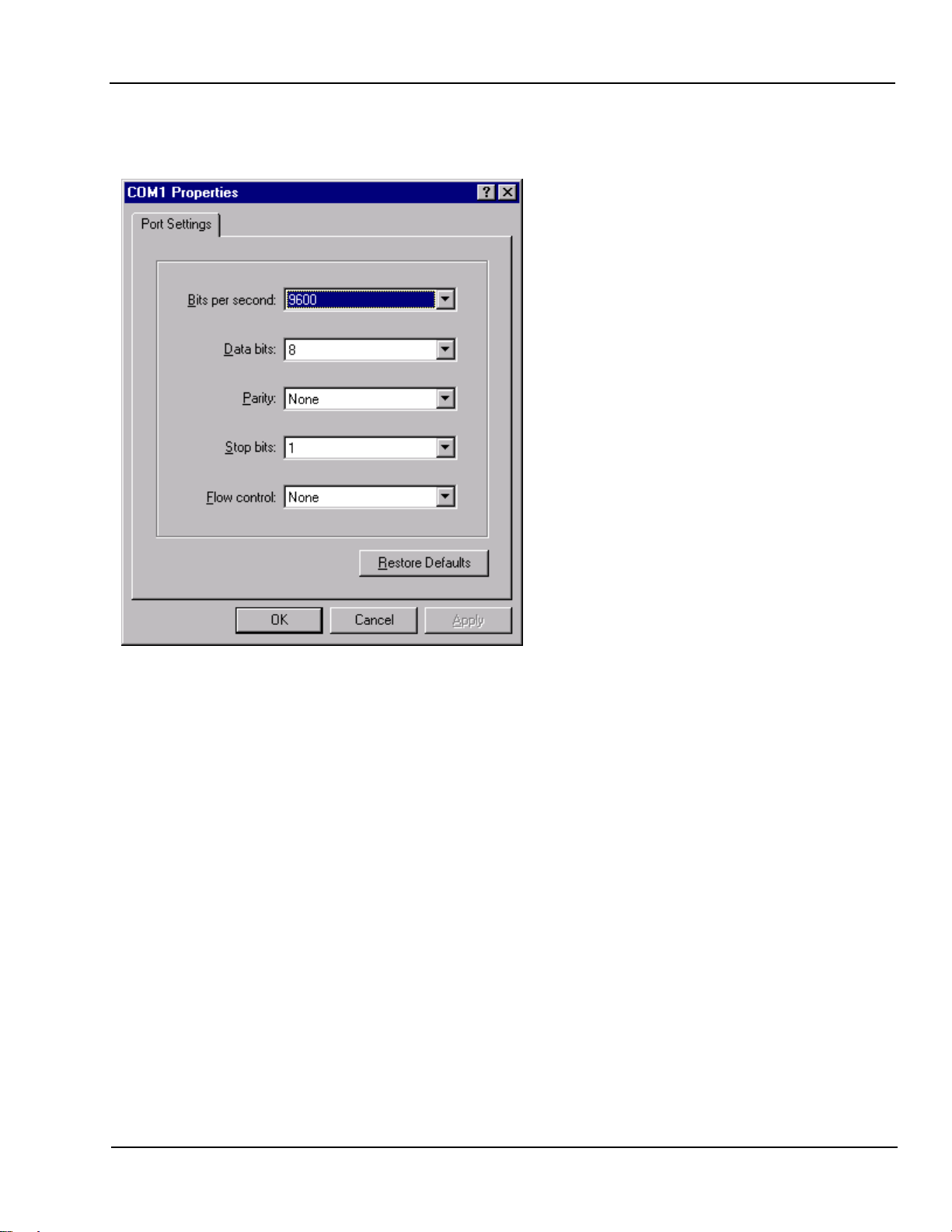
5. Set the port settings as shown in the example in Figure 2-3. Now click OK.
Figure 2-3. HyperTerminal Port Settings.
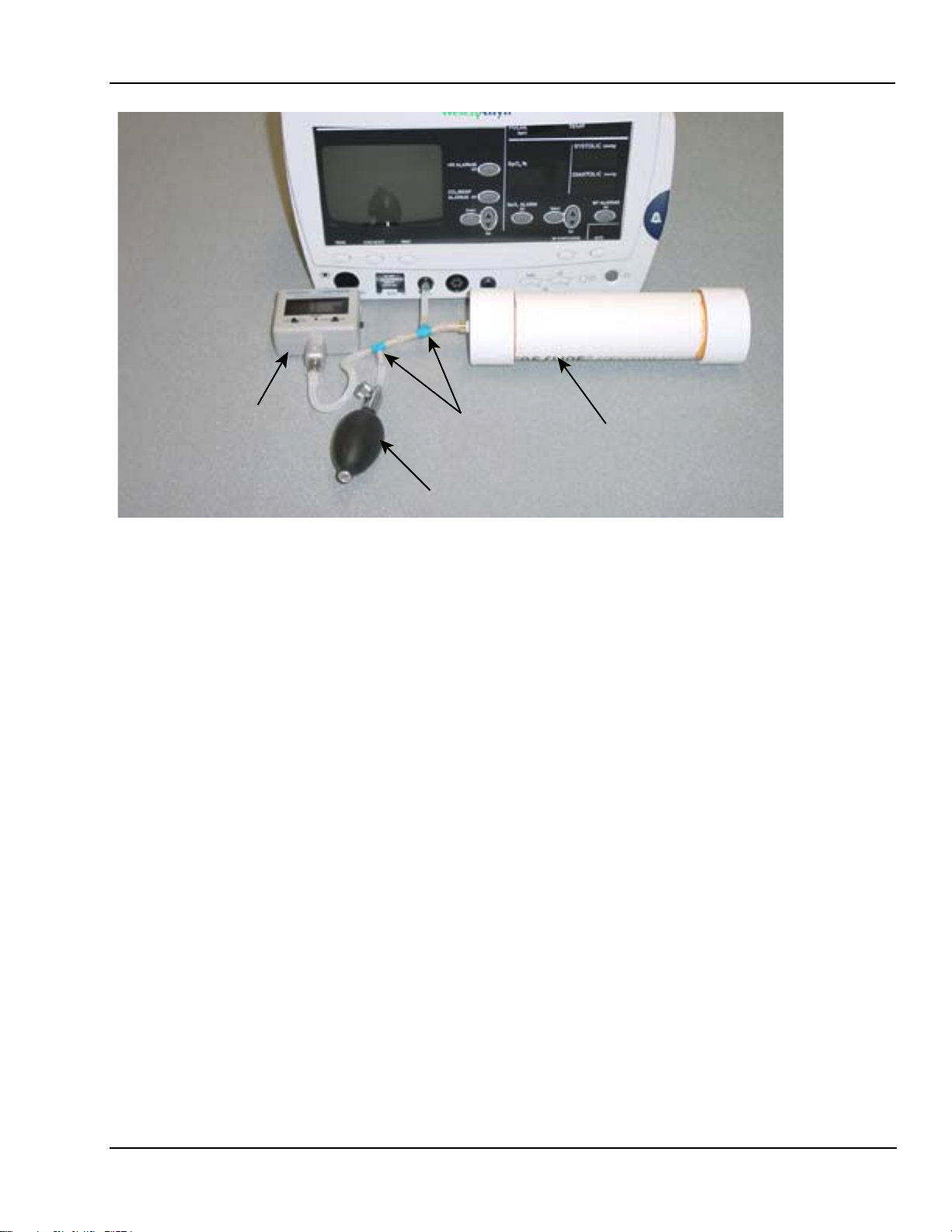
6. Connect the pressure meter, bulb, and 500cc vessel to BP port with “T” connectors as
shown in photograph Figure 2-4.
7. Connect the Atlas to PC with serial cable.
8. Turn the Atlas on. Start HyperTerminal on PC. Press the <Enter> key and you should see
a Pangea> prompt.
NOTE: Take no more than 3 minutes for the 50mmHg calibration nor more than 3 minutes
for the 250mmHg calibration as the Atlas will automatically, as a safety feature, open the
blood pressure valve. If this happens you will have to turn the Atlas off then back on again
and restart the calibration again.
16 Welch Allyn Atlas Monitor Service Manual 6200-43E Rev. D
Page 29
Service Section 2
T112854
Pressure
Meter
Figure 2-4. Photo of Atlas BP calibration setup.
T Fittings
Squeeze Bulb
Calibrated 500cc Volume
50mmHg Calibration
1. Enter the following commands at the Pangea prompt.
Pangea> bp valve close <ENTER>
Pangea> bp safety off <ENTER>
Pangea> bp cal 5000 Do not press <ENTER> yet!
2. Raise the pressure with bulb to as close to 50.00mmHg as possible. Now press <ENTER>.
3. Release the pressure.
250mmHg Calibration
1. Enter the following command
Pangea> bp cal 25000 Do not press <ENTER> yet!
2. Raise the pressure with bulb as close to 250.00 mmHg as possible. Now press < ENTER >
3. Enter the following command to save the calibration in the Atlas.
Pangea> nvram write <ENTER>
4. Release the pressure.
Service Manual 6200-43E Rev. D Welch Allyn Atlas Monitor 17
Page 30

Section 2 Service
CO2 Reset (623xx Models Only)
Required material. 1. Watertrap
2. Scrubber
NOTE: The Scrubber looks similar to a watertrap, but it is filled with white granules. The
scrubber is included with the 623XX models only.
NOTE: Make sure date and time are correct before performing the CO2 reset.
1. Turn Atlas on. Make sure the watertrap and scrubber are NOT attached to the Atlas.
2. Press the DATE/TIME button on the lower right of the monitor. The Set Date and Time
and Other Options menu will be displayed.
3. Press the CO2/RESP ALARMS Off button. The CO2 Reset screen will appear.
4. You will see the following messages on the CRT.
“CO2 Reset”
“Install CO2 scrubber”
“Press Trend to abort”
5. Install the watertrap to the Atlas. Install the scrubber to the watertrap.
6. You will see the following instructions on the screen.
“Warming up” will be flashing on CRT.
“May take up to five minutes” on CRT.
“Press Trend to abort” on CRT.
7. After about 5 minutes you will see on the CRT.
“CO2 Reset”
“Reset complete”
“Remove CO2 scrubber”
“Press the trend button to exit”
8. Remove the CO
watertrap and scrubber.
2
9. Press TREND button to return to idle screen.
Replace watertrap after every six hours of use. Treat watertrap and used CO2
sample lines as bio hazard material!
18 Welch Allyn Atlas Monitor Service Manual 6200-43E Rev. D
Page 31

Service Section 2
ET CO2 Calibration
Required material:
1. Tank of approximately 10% CO2, balance N2 (certified) Blood Gas Mixture.
2. Tubing and T connectors.
3. Watertrap and scrubber.
1. Make sure the watertrap and scrubber are not attached to the Atlas. Turn the Atlas on.
2. Place the instrument into the Service Mode by pressing the DATE/TIME button. Make
sure date and time are correct. Press the LEAD SELECT button.
3. Press SELECT button and scroll down to Calibrate CO2.
The message “Install CO2 Scrubber” will appear on the right side of screen.
4. Attach the scrubber to the water trap.
5. Insert the scrubber/water trap assembly into water trap socket. The message
“Enter span gas value using Set button 10%” will appear.
6. Press the SET button to change the value of span gas being used. The factory default
value is 10%. Calibrate with a 8% to 12% certified CO2 concentration known to be
±0.01%).
7. The message press “BP Start/Cancel” will appear at the bottom right of CRT. Press the
BP/Start/Cancel button.
8. If you receive a “Calibration Failed” message at this point, check the date. If date is
2022 or above it will fail CO2 calibration.
9. Next you will see a message “Warming up”. After the Atlas warms up you will see a
message “Attach CO2 gas”. Remove the scrubber from the CO2 water trap. Do not
remove water trap.
10.Attach the certified source of CO
gas to the CO2 side-stream sampling tube as per
2
Figure 2-5 below.
Service Manual 6200-43E Rev. D Welch Allyn Atlas Monitor 19
Page 32

Section 2 Service
Adjust Regulator to
Approximately 2 psi
Water
Trap
Vent
2
CO
Figure 2-5. Example of CO2 calibration setup.
CAUTION: IMPROPER USE,STORAGE OR HANDLING OF COMPRESSED
GAS VESSELS CAN CAUSE DEATH OR INJURY. FOLLOW GAS MANUFACTURES SAFETY PROCEDURES!
11.Adjust the CO2 regulator just enough to allow a small amount of gas to flow out of the
vent (approximately 2 psi).
12.Press the BP START/CANCEL button. The message: “Sampling” will appear on CRT.
“CO2 calibration successful” or “CO2 calibration failed” will appear on the CRT
display.
13.Press the TREND button to exit.
No-Load Battery Voltage Calibration
NOTE: No-Load Battery Voltage Calibration procedure is for models 622 and 623 only. If
you disconnect the battery you must reset time and date after you reconnect the battery.
Specifications: No load battery charge 6.85 VDC
Required materials: DVM
1. Remove the battery and disconnect the battery leads from the Atlas. Use the DVM to
measure across the connectors, red+ and black-.
2. Adjust the voltage to 6.85 VDC by turning potentiometer R338, located behind the right
battery jack. Turning clockwise will increase the no-load voltage and counter clockwise
will decrease the no-load voltage.
20 Welch Allyn Atlas Monitor Service Manual 6200-43E Rev. D
Page 33

Service Section 2
Battery Voltage Calibration
Required materials.
1. DC power supply rated: 7 VDC at 5A
2. DMM / DVM with 10mV resolution on a 10 DC volt scale.
3. PC with HyperTerminal
4. Serial interface cable
1. Connect the serial cable to the PC and Atlas.
2. Hyper Terminal Settings are:
9600 Baud, 8 bit word, 1 stop bit
no parity, no flow control
ANSI character set
Find HyperTerminal in Windows 95 or higher
Start !Programs!Accessories ! Communication! HyperTerminal
NOTE: Make sure the Atlas IS NOT plugged into AC for this calibration procedure.
3. Remove and disconnect the battery from Atlas.
4. Set the power supply to 6.8VDC " 200mV and connect the power supply to the battery
connector on the Atlas.
5. Turn Atlas on..
6. Reduce the power supply to 6.0VDC and measure the voltage at the battery connector
(at the Atlas) to the nearest 10mV.
NOTE: Do not measure at the power supply, since cable resistance will introduce error.
7. At the HyperTerminal prompt type:
Pangea> power cal XXXX <ENTER>
NOTE: XXXX represents the measured voltage in millivolts no decimal point. For
example, if you measured 6.010VDC at the battery connector, use the command “power cal
6010 <ENTER>”.
8. The Atlas will respond: raw = ZZZZ mV true = 6010 mV OK
NOTE: ZZZZ is the raw uncalibrated reading that the instrument made.
9. Reduce the power supply to 5.6 VDC. You should soon hear the “low battery” alarm.
10.Measure the voltage at the battery connector to the nearest 10mV.
Service Manual 6200-43E Rev. D Welch Allyn Atlas Monitor 21
Page 34

Section 2 Service
11.At the HyperTerminal prompt type:
Pangea> power cal XXXX <ENTER>
NOTE: XXXX represents the measured voltage in millivolts with no decimal point. For
example if you measured 5.590 volts at the battery connector, then you would enter the
command “power cal 5590” <ENTER>.
12.The Atlas will respond:
raw = ZZZZmV true = 5590 OK
NOTE: ZZZZ is the raw uncalibrated reading that the instrument made.
13.Finish the calibration by typing:
Pangea> hw reset <ENTER>
NOTE: This will re-boot the Atlas.
14.Turn the Atlas off and reinstall the battery.
15. Reset time and date.
Printer Print Adjustment
1. Install new paper.
2. Turn Atlas on.
3. Attach an ECG simulator to Atlas and set simulator for a heart rate of 60 bpm, normal
sinus rhythm.
4. Press PRINT button. Evaluate the darkness of waveform and text printout.
5. If either need to be changed press DATE/TIME button then press LEAD SELECT button
to access Advanced Configuration menu.
6. Press SELECT button and scroll down to Printer Test Pattern. Then Press
HR ALARMS OFF button
7. Two lines will be displayed:
1. Waveform+128
2. Text+ 78
NOTE: These two numbers are the factory defaults and are a good starting point if the system is printing poorly or not at all.
22 Welch Allyn Atlas Monitor Service Manual 6200-43E Rev. D
Page 35

Service Section 2
8. The left SET button controls the waveform darkness and the right SET button controls
the text darkness.
NOTE: Pressing the SET button up will increase the number and darken the waveform
while pressing the SET button down will decrease the number and will lighten the waveform.
9. Make changes to the printout as needed.
10.Press Trend button to return to waveform screen.
Temperature Calibration
Required Material:
1. PC with Windows7 95 or higher 4. 1/4O mono phono jack
2. Atlas serial cable 5. Soldering iron and solder
3. 1k Ohm, 1/2 watt precision resistor 6. Ohm Meter
1. Solder the 1 K Ohm resistor to 1/4” mono phono jack.
2. Measure the resistance at the tip of the phono jack. Record that resistance reading, to two
decimal points.
3. Plug the phono jack into the Atlas.
NOTE: The Atlas will show a temperature reading in the temperature display.
4. Start HyperTerminal on PC.
5. Hyper Terminal Settings are:
9600 Baud, 8 bit word, 1 stop bit
no parity, no flow control
ANSI character set
Find HyperTerminal in Windows7 95 or higher
Start !Programs ! Accessories ! Communication ! HyperTerminal
6. At the Pangea prompt Type: PANGEA> temp cal XXXXXX <ENTER>
NOTE: XXXXXX is the resistance reading you measured and recorded in milliohms at the
tip of the mono phono jack.
Example: If you measure 1000.40 ohms at the tip of the phono jack then you would type
temp cal 100040 <Enter>.
7. Wait four seconds then type: PANGEA> temp state <ENTER>. You will see a value
returned at the Pangea prompt.
Service Manual 6200-43E Rev. D Welch Allyn Atlas Monitor 23
Page 36

Section 2 Service
8. Verify that the resistance given by the above command returns a value " 0.5 ohms.
9. Verify temperature accuracy as outlined in Chapter 3, Table 3-2.
Calibration Date Set
NOTE: After calibrating the Atlas you must reset the calibration date. The calibration date
is the date you performed the calibration. The calibration date appears in the Service Mode
menu. See Figure 2-6 for an explanation of the Service screen.
1. At the Pangea prompt type.
Pangea> nvram set cal_date XXXX <ENTER>
NOTE: XXXX is the number of days from January 1, 1998 until the present date. See
APPENDIX E for that number or calculate manually.
24 Welch Allyn Atlas Monitor Service Manual 6200-43E Rev. D
Page 37

Service Section 2
Explanation of an Atlas Service Screen
Service Mode
Select a test
Verifyff manomete
Reset to factory default
Battery test
Calibrate CO2
CRT test pattern
Printer test pattern
LED test
Button test
Display A/D channels
0.00
A
B
C
D
Model 220 with printer Cal:27 Nov 2002
Sn: 62304064 Sw: BB.025000 Boot: AA.01.0000
SpO2: NELLCOR MP506 V1.8.0 6/21/02
CO2 1.0 V3 .00 #2542 Cal: 27 Nov 2002 14 Nov 200 2
Press the Trend button to exit
Figure 2-6. Example and Explanation of an Atlas Service Screen
Line A Indicates that the Atlas is a model 220 and that the Atlas has a printer. If the Atlas
did not have a printer then the text “with printer” would be absent. The date field following
indicates the date the Atlas was last calibrated.
Line B starts with a numeric sequence. The first three digits are the model number of the
Atlas. The next five numbers are the Atlas serial number. The next sequence,alphanumeric,
indicates what software version is currently loaded into the Atlas. The third sequence,
alphanumeric, indicates what version boot software is currently loaded into the Atlas.
Line C starts with the SpO2 OEM board used in the Atlas. There are two SpO2 OEM boards
used in the Atlas. One is Nellcor and the other is Nonin. The next sequence indicates the
model of the SpO2 board. The next sequence, that starts with a letter “V”, is the version software used with the current SpO2 board. The date following the SpO2 software is the date
the OEM loaded the software into the SpO
board. SpO2 OEM software can not be upgraded.
2
If the most current software is needed, you will need to replace the SpO2 board.
Line D is the CO
installed. If your Atlas does not have CO
information if your Atlas has CO
2
installed then line D will be absent. If your Atlas
2
installed. Only models 623 have CO2
2
has CO2 installed then line D will start with CO2 followed by a numeric number. That
numeric value is the software loaded into the CO
board. The next alphanumeric sequence,
2
starting with a “V”, is the version of that software. The next numeric sequence starting with
a “#” is the serial number of the CO2 board. The next sequence, a date, is the date the CO2
was last calibrated. The last sequence, a date, is the date the CO2 was reset. CO2 OEM software can not be upgraded. If the current software is needed, you will have to replace the
CO2 board.
Service Manual 6200-43E Rev. D Welch Allyn Atlas Monitor 25
Page 38

Section 2 Service
Table 2-3. Software Revision Table.
Model Operating System Boot loader Nellcor Nonin Pryon
621S0 AA.01.4000, 9/8/99 AA.01.0000, 6/20/99 V7
621S0 BB.02.0000, 4/4/01 AA.01.0000, 6/20/99 V7
621S0 BB.02.2000, 6/4/02 AA.01.0000, 6/20/99 V7
621S0 BB.02.5000, 10/14/02 AA.01.0000, 6/20/99 V7
621N0 BB.02.5000, 10/14/02 AA.01.0000, 6/20/99 V1.8.1.0, 10/14/02
621SP AA.01.4000, 9/8/99 AA.01.0000, 6/20/99 V7
621SP BB.02.0000, 4/4/01 AA.01.0000, 6/20/99 V7
621SP BB.02.2000, 6/4/02 AA.01.0000, 6/20/99 V7
621SP BB.02.5000, 10/14/02 AA.01.0000, 6/20/99 V7
621NP BB.02.5000, 10/14/02 AA.01.0000, 6/20/02 V1.8.1.0, 10/14/02
622S0 AA.01.4000, 9/8/99 AA.01.0000, 6/20/99 V7
622S0 BB.02.0000, 4/4/01 AA.01.0000, 6/20/99 V7
622S0 BB.02.2000, 6/4/02 AA.01.0000, 6/20/99 V7
622S0 BB.02.2000, 6/4/02 AA.01.0000, 6/20/99 V7
622S0 BB.02.5000, 10/14/02 AA.01.0000, 6/20/99 V7
622SP AA.01.4000, 9/8/99 AA.01.0000, 6/20/99 V7
622SP BB.02.0000, 4/4/01 AA.01.0000, 6/20/99 V7
622SP BB.02.2000, 6/4/02 AA.01.0000, 6/20/99 V7
622SP BB.02.5000, 6/14/02 AA.01.0000, 6/20/99 V7
622N0 AA.01.4000, 9/8/99 AA.01.0000, 6/20/99 V 1.2.0.0 12/17/97
622N0 BB.02.0000, 4/4/01 AA.01.0000, 6/20/99 V 1.2.0.0 12/17/97
622No BB.02.2000, 6/4/02 AA.01.0000, 6/20/99 V 1.2.0.0 12/17/97
622N0 BB.02.5000, 10/14/02 AA.01.0000, 6/20/99 V 1.8.1.0 10/14/02
622NP AA.01.4000, 9/8/99 AA.01.0000, 6/20/99 V 1.2.0.0 12/17/97
622NP BB.02.0000, 4/4/01 AA.01.0000, 6/20/99 V 1.2.0.0 12/17/97
622NP BB.02.2000, 6/4/02 AA.01.0000, 6/20/99 V 1.2.0.0 10/14/02
622NP BB.02.5000, 10/14/02 AA.01.0000, 6/20/99 V 1.8.1.0 10/14/02
623SP AA.01.4000, 9/8/99 AA.01.0000, 6/20/99 V7 0.E V1.00
623SP BB.02.0000, 4/4/01 AA.01.0000, 6/20/99 V7 0.E V1.00
623SP BB.02.2000, 6/4/02 AA.01.0000, 6/20/99 V7
622SP BB.02.5000, 10/14/02 AA.01.0000, 6/20/99 V7
623NP AA.01.4000, 9/8/99 AA.01.0000, 6/20/99 V 1.2.0.0 12/17/97 0.E V1.00
623NP BB.02.0000, 4/4/01 AA.01.0000, 6/20/99 V 1.2.0.0 12/17/97 0.E V1.00
623NP BB.02.2000, 6/4/02 AA.01.0000, 6/20/99 V 1.2.0.0 12/17/97
623NP BB.02.5000, 10/14/02 AA.01.0000, 6/20/99 V 1.8.1.0 10/14/02
26 Welch Allyn Atlas Monitor Service Manual 6200-43E Rev. D
Page 39

Service Section 2
Software Upgrade Procedure
NOTE: The following procedures are required to upgrade the software on a fully functioning Atlas or to reload software after replacing the CPU board. The download utility
“atlas_dl.exe” loads the following files automatically.
1. atlas.out.gz
2. nvram_common.txt
3. nvram_(model#).txt
4. nvram_(language).txt
“Atlas_dl.exe” will also query the Atlas to determine what model number the Atlas is and
what language to download.
Equipment or supplies required:
1. PC with Windows7 95 or higher
2. Atlas serial cable
3. File: atlas_dl.exe (Included in the Atlas Repair Software listed in Table2-2.)
NOTE: Make sure you have HyperTerminal turned off or the following utility download will
not work!
1. Run the program atlas_dl.exe from the CD or copy the file to your hard drive and run the
program from there.
2. Connect the serial cable between the Atlas and the PC s’“COM1 port”.
3. Turn your computer on and locate the “atlas_dl.exe” file.
4. Double left click on the “atlas_dl.exe” file.
5. When the file starts to download, the CRT will go blank on the Atlas.
NOTE: Do not use the computer while the program is downloading.
6. After down loading is complete, check all alarm settings and all user advanced
configuration settings since these are RESET by this utility software download
procedure.
NOTE: Stop here if you are just upgrading software on a fully functional Atlas monitor or if
you have replaced the CPU board.
NOTE: If you have replaced the MAIN BOARD then you MUST continue with the next
procedure (DOWNLOADING NVRAM FILES).
NOTE: Perform the following NVRAM downloading procedure if you have replaced the
MAIN BOARD. The NVRAM resides on Main Board.
Service Manual 6200-43E Rev. D Welch Allyn Atlas Monitor 27
Page 40

Section 2 Service
Down Loading NVRAM Files
Required Materials.
1. Computer with Windows7 95 or higher.
2. The latest Atlas repair software. Call your local Welch Allyn
representative.
1. Once you have procured the latest Atlas Repair Software, you will be able
to run the programs straight from the CD or copy the files to your hard drive.
NOTE: Through HyperTerminal you will need to load the following files:
1. nvram_cal_init.txt
2. nvram_common.txt
3. model# of Atlas
3.1.You will load “nvram200.txt” if your Atlas is a model 621xx.
3.2.You will load “nvram210.txt” if your Atlas is a model 622xx.
3.3 You will load “nvram220.txt” if your Atlas is a model 623xx.
4. “language.txt”Any combination of or all of the following files
4.1 “nvram_english.txt” for the English language
4.2 “nvram_french.txt” for the French language
4.3 “nvram_german.txt” for the German language
4.4 “nvram_spanish.txt” for the Spanish language
4.5 “nvram_potuguese.txt” for the Portuguese language
4.6 “nvram_italian.txt” for the Italian language
4.7 “nvram_chinese.txt” for the Chinese language
4.8 “nvram_japanese.txt” for the Japanese language
5. printer.txt (if fitted with a printer), or no_printer.txt. (if not fitted with a printer)
NOTE: After loading the preceding files you, must then type the following commands at
the Pangea prompt.
1. “nvram set serial xxxxx” where xxxxx is the serial number of the Atlas monitor.
2. “nvram write” writes the information to memory.
3. “hw reset” performs a hardware reset.
2. Connect the serial cable between the Atlas and the PC COM1 port.
3. Open HyperTerminal program on PC.
Hyper Terminal Settings are:
9600 Baud, 8 bit word, 1 stop bit
no parity, no flow control
ANSI character set
Find HyperTerminal in Windows7 95 or higher
Start !Programs ! Accessories ! Communication ! HyperTerminal
28 Welch Allyn Atlas Monitor Service Manual 6200-43E Rev. D
Page 41

Service Section 2
4. Turn Atlas on. You should see the Pangea prompt. See example in Figure 2-7.
Figure 2-7. Pangea prompt in HyperTerminal.
5. Scroll over to “Tran sf er ” and then scroll down and choose “Send Text File”.
See example in Figure 2-8.
Figure 2-8. Choosing “Send Text File” in HyperTerminal.
6. Another window will then appear and prompt you for the location of the files. Double
left click on that folder to open that directory. You can also run these programs from the
CD. See example in Figure 2-9.
Service Manual 6200-43E Rev. D Welch Allyn Atlas Monitor 29
Page 42

Section 2 Service
Figure 2-9. Choosing directory where NVRAM files are stored.
7. Once the folder is open, open the file “nvram_cal_init.txt” file by double left clicking on
that file or by high lighting the file and then click on the Open button. See example in
Figure 2-10.
Remember that after you have download the files in this section and you must
complete this entire “Downloading NVRAM files” section, that you must perform
a complete calibration on the Atlas monitor.
Figure 2-10. Choosing the nvram_cal_init.txt file.
30 Welch Allyn Atlas Monitor Service Manual 6200-43E Rev. D
Page 43

Service Section 2
NOTE: After the nvram_cal_init.txt has executed you should see a Pangea screen similar to
window as shown in Figure 2-11.
Figure 2-11. Pangea screen after opening the nvram_cal_init.txt file.
8. From your pangea window choose Transfer then choose Send Text File.
9. Open the directory where the file nvram_common.txt is located or open from the CD.
10.Double left click on nvram_comm.txt file or highlight the file and then choose Open.
NOTE: After opening the nvram_common.txt file you should see a screen similar to the
window shown in Figure 2-12.
Figure 2-12. Pangea screen after opening the nvram_common.txt file.
Service Manual 6200-43E Rev. D Welch Allyn Atlas Monitor 31
Page 44

Section 2 Service
NOTE: Next you will download the model# of the Atlas by choosing only one of the three
following files.
1. If you have an Atlas model 621 then you will only download the file nvram200.txt.
2. If you have an Atlas model 622 then you will only
3. If you have an Atlas model 623 then you will only
11.Open the directory where the model number files are located or open from CD.
12.Open the file by double left clicking on the file that represents the model number of the
Atlas you are working on or highlight that file then choosing Open.
NOTE: After opening the Atlas model# file you should see a Pangea screen similar to the
window as shown in Figure 2-13.
download the file nvram210.txt.
download the file nvram220.txt.
Figure 2-13. Pangea prompt after opening the model# file.
32 Welch Allyn Atlas Monitor Service Manual 6200-43E Rev. D
Page 45

Service Section 2
NOTE: Next you will download the language(s) that you want the Atlas to store in it’s
Advanced Configuration menu for languages. You can have one or all the languages loaded
in the Atlas. Listed in Table 2-4 are the language(s) choices and the files you will need to
download to have the language(s) loaded in the Atlas. Each language you want loaded in
the Atlas will require that the file associated with that language be loaded.
Table 2-4. Files needed to download language(s).
Language File needed to download
English nvram_english.txt
French nvram_french,txt
Spanish nvram_spanish.txt
German nvram_german.txt
Portuguese nvram_portuguese.txt
Italian nvram_italian.txt
Chinese nvram_chinese.txt
Japanese nvram_japanese.txt
13.Open the directory where the language files are located or open from CD.
14.Double left click on language.txt file or highlight the file and then choose Open.
NOTE: After you download a language.txt file you should see a Pangea screen similar to
Figure 2-14.
Figure 2-14. Pangea screen after loading a language file.
Service Manual 6200-43E Rev. D Welch Allyn Atlas Monitor 33
Page 46

Section 2 Service
NOTE: Next you tell the Atlas if it does or does not have a printer.
1. If the Atlas has a printer you will download the file nvram_printer.txt.
2. If the Atlas does not have a printer then you will download the file
nvram_no_printer.txt.
15.Open the directory where the printer.txt files are located or open from CD.
16.Double left click on the printer file or the no_printer file or highlight the printer file or
the no_printer file and then choose Open.
NOTE: After you have downloaded the printer or no_printer file you should see a Pangea
screen similar to the window as shown in Figure 2-15.
Figure 2-15. Pangea screen after downloading the nvram_printer.txt file.
NOTE: The next three commands will require that you actually type the command at the
Pangea prompt.
NOTE: XXXXX on line 17 is the Atlas 5 digit serial number. The serial number is located on
the bottom of the Atlas. Make sure that you have a space between the command serial and
the five numbers you are entering.
17.At the Pangea prompt type the following command “nvram set serial XXXXX”<ENTER>
NOTE: After you have typed the nvram set serial XXXXX command and hit ENTER you
should see a Pangea screen similar to the example in Figure 2-16.
34 Welch Allyn Atlas Monitor Service Manual 6200-43E Rev. D
Page 47

Service Section 2
Figure 2-16. Pangea screen after you have downloaded the nvram set serial command.
NOTE: To finish downloading the NVRAM files, type the next two commands at the Pangea
prompt.
18.At the Pangea prompt type the command nvram write <ENTER>.
19.At the Pangea prompt type the command hw reset <ENTER>.
NOTE: The hw reset command will reboot the Atlas.
Remember that after you have download the files in this section and you must
complete this entire “Downloading NVRAM files” section, that you must
a com
plete calibration on the Atlas monitor.
perform
NOTE: The firmware is not up grade able on the OEM boards (SpO2 and CO2) boards. If a
higher version software is needed, then you will need to replace the OEM board.
Service Manual 6200-43E Rev. D Welch Allyn Atlas Monitor 35
Page 48

Page 49

Troubleshooting Section 3
NOTE: Review customer complaint and determine if it is safe to plug in the Atlas monitor
into AC power and if it is safe to turn on!
Power on Self Test
1. Plug in Atlas into AC power with no sensors attached. Verify that the AC~ LED indictor
is lit. Install paper in printer if fitted.
2. Turn on power and verify the following:
1. Green light in power button.
2. Loud beep when Power On button pressed.
3. Three dashes in SYSTOLIC.
4. Three dashes in DIASTOLIC.
5. Two dashes in SpO2 (takes several seconds after BP dashes come on).
6. Three dashes in PULSE (takes several seconds after BP dashes come on).
7. Single bar at the bottom of Plethysmograph.
8. No lights in TEMP.
9. No lights in ALARMS OFF buttons.
10. X lit on AUTO.
11. CRT display may comes on slowly if cold or quickly if still warm from last use.
12. May see version string in center if comes on quickly. It is not a problem if not seen
because it comes on slowly.
3. On the CRT you should see:
1. Three dashes for Heart Rate
2. Heart symbol
3. Lead select symbol
4. Scale bar
5. One or two lines of dashes for waveforms – depends upon settings.
6. Three dashes for MAP – or blank, depending upon settings.
7. Error message(s) at bottom of screen?
4. On models 622 or 623, disconnect AC cable. You should see no change except the
AC~ LED indicator will not be lit. If you see warnings of a low, very low or depleted
battery, or if the system turns off by it’s self, plug the Atlas back into the AC outlet and
let the unit charge with unit turned off. Repeat test in 2 hours.
5. Plug the monitor back into AC.
Service Manual 6200-43E Rev. D Welch Allyn Atlas Monitor 37
Page 50

Section 3 Troubleshooting
Menu Functional Test
1. Press DATE/TIME button to enter menu page. Press TREND button to access the
Advanced Configuration menu.
2. Write down all configuration settings so that they can be reset to customer preferences
later. If you have a printer press the PRINTER button to print out customer configuration
settings.
3. Set language to your native tongue if necessary to allow you to write down the other
settings. The top item is always the language, press either SET buttons to step through
list.
4. Press TREND button to return to idle screen. Press DATE/TIME button and verify that
date and time are correct. Set date and time if necessary.
NOTE: An incorrect date may indicate a battery problem. If date was incorrect, turn off
unit, disconnect AC power cable, wait 5 minutes then reconnect the power cable. Turn Atlas
on. Check date again. If date comes back incorrect on model 621 then replace main board.
On model 622 and 623, if battery was not dead then replace main board.
5. Press DATE/TIME button to return to waveform screen if needed.
6. Press DATE/TIME button then press LEAD SELECT button to access service mode
7. Version/configuration data is in lower half of menu, write it all down.
8. Press SELECT button to highlight reset to factory defaults.
9. Press BP START/CANCEL button to reset configuration.
10. Press TREND button to return to idle screen.
11. Press DATE/TIME button then press TREND button to access the Advanced
Configuration menu.
12. Set language to your native tongue if necessary
NOTE: We have just reset the monitor to factory defaults. Compare settings to factory
defaults appropriate for the country in Operator manual. If the factory defaults do not
match then that may indicate a memory problem. Changing only the language should not
change any of the other factory default settings.
13. Press DATE/TIME button then press LEAD SELECT button to access service mode.
14. Press SELECT button to highlight CRT test pattern.
38 Welch Allyn Atlas Monitor Service Manual 6200-43E Rev. D
Page 51

Troubleshooting Section 3
15. Press BP START/CANCEL button to show test pattern. Examine display. Press any key to
end display.
16. Press Select button to highlight Printer test pattern (if fitted). Press BP START/CANCEL
button to start test pattern. Printer should print a test pattern. Press any key to end
display. Examine printout.
17. Press SELECT button to highlight LED test. Press AUTO button to turn on all LEDs.
Press BP START/CANCEL button to show automatic test pattern. Watch for a while,
look for glitches in pattern. Press SET button to go to manual mode and step through
individual segments if needed to observe a problem.
18. Press SELECT button to highlight Button test. Press BP START/CANCEL button to
start test. Press every button on system, press BP START/CANCEL button last.
Verify that buttons match up with their names and that all buttons are functional.
NOTE: If name does not correspond to the button pushed then this may indicate memory
corruption. You may need to replace the main board.
19. Press SELECT button to highlight Display A/D channels. Press SET button and write
down all values for each of the four screens for later review. Press TREND button to
return to Idle screen.
Service Manual 6200-43E Rev. D Welch Allyn Atlas Monitor 39
Page 52

Section 3 Troubleshooting
BP Test
1. Press DATE/TIME button then press TREND button to access the Advanced
Configuration menu. Press SELECT button to highlight Initial pressure. Press SET button
to change Initial pressure to 280 mmHg. Press SELECT button to highlight MAP. Press
SET button to change MAP to Yes. Press TREND button to return to idle screen.
2. Connect the BP port to the BP simulator. Set the simulator for a normal reading
(140/80, 100BPM, NSR). Press BP START/CANCEL button. Atlas should start to
pump and display a manometer value in SYSTOLIC LED. This value should track
and be very close to pressure displayed by manometer on BP simulator (if fitted).
Largest number shown in SYSTOLIC LED should be very close to the initial pressure
setting recorded above from Advanced Configuration. System should start stepping
down pressure, showing step values in SYSTOLIC LED display. It then should display
the correct SYSTOLIC and DIASTOLIC values. System may show MAP value depending
upon country language setting.
3. Press BP START/CANCEL button. System should start pump, display manometer
value in SYSTOLIC LED. This value should track and be very close to pressure
displayed by manometer in BP simulator (if fitted). Largest number shown in
SYSTOLIC should be very close to the Initial pressure setting of 280 mmHg. If
pressure shown exceeds 300 mmHg then re calibrate the Atlas BP.
4. System should start to step down pressure, showing step values in SYSTOLIC LED and
then display correct SYSTOLIC and DIASTOLIC values. System should show MAP
value. MAP value should match what is shown by simulator.
5. Set simulator to (120/70, 60 (beats per minute)bpm, NSR).
6. Press the AUTO button. The X manual BP cycle indicator will go out and the 1 minute
auto BP cycle indicator will flash for 10 seconds. 20 seconds after the 1 minute auto BP
cycle indicator stops flashing, BP measurement starts.
7. Verify the BP reading. If BP measurement incorrect recalibrate.
8. No less than 30 seconds after completing the measurement another measurement
should start. While it is pumping up, press the BP START/CANCEL button.
Measurement should stop immediately and pressure should be dumped (as seen on
the simulator manometer).
9. Press AUTO button and X manual BP cycle indicator should light (not flashing).
10. Disconnect the tubing from the BP port on the Atlas. Press BP START/CANCEL
button and note the time (to the second) when the Atlas aborts the BP cycle and gives
you an alarm. It should take no longer than 1 minute. Turn Atlas off.
40 Welch Allyn Atlas Monitor Service Manual 6200-43E Rev. D
Page 53

Troubleshooting Section 3
Static Manometer Accuracy Test
Required materials.
1. Serial interface cable
2. PC with HyperTerminal (Windows 95 or above)
3. 500cc vessel with inflation system.
4. Calibrated manometer
1. Turn computer on and activate Hyper terminal.
Hyper Terminal Settings are:
9600 Baud, 8 bit word, 1 stop bit
no parity, no flow control
ANSI character set
Start !Programs ! Accessories ! Communication ! HyperTerminal
2. Turn Atlas on. Refer to Figure 2.1 in Section 2 for inflation setup.
3. Enter the following commands at the PANGEA> prompt.
PANGEA> bp safety off <ENTER>
PANGEA> bp valve close <ENTER>
4. Pressurize the Atlas monitor to the applied pressures in Table 3-1.
5. To compare the applied pressure to the transducer readings use the following command.
PANGEA> bp press <ENTER>
Table 3-1. Transducer pressure table.
Applied
Pressure
0 mmHg
50 mmHg
150 mmHg
250 mmHg
Primary
Transducer
Safety
Transduce r
"0.75 mmHg "1.0 mmHg
"1.5 mmHg "1.5 mmHg
"1.5 mmHg "4.5 mmHg
"1.5 mmHg "7.5 mmHg
6. Verify that the primary transducer and secondary transducer are within the
specifications listed in Table 3-1.
NOTE: The Atlas monitor will return a response to the computer screen as follows.
If you tested at the 50mmHg pressure you would receive a message similar to: px = 5279,
sx = 5305 x 0.01. Where px is the primary transducer and 5279 = 52.79 mmHg and sx is the
secondary transducer and 5305 = 53.05 mmHg.
Service Manual 6200-43E Rev. D Welch Allyn Atlas Monitor 41
Page 54

Section 3 Troubleshooting
BP Leak Test
NOTE: Unit must not leak more than 5 mmHg in a 15 second interval while attached to a
100cc test cavity pressurized at 50 mmHg, 150 mmHg and 250 mmHg.
Required Materials: 100cc test vessel (+10cc/-0cc), stopwatch, squeeze bulb, calibrated
manometer.
1. Connect Atlas to 100cc test vessel and calibrated manometer as shown in Section 2,
Figure 2.1.
2. Turn Atlas on.
3. Press DATE/TIME button then press LEAD SELECT button to access the Service Mode.
4. Press SELECT button and choose Verify manometer.
5. Pressurize the Atlas with squeeze bulb to 50mmHg and allow reading to stabilize.
6. Observe pressure for 15 seconds.
6. Unit should not leak more than 5mmHg during this time.
7. Repeat this process at 150mmHg and 200mmHg.
Over 15 mmHg Test
NOTE: Atlas hardware must detect if the pneumatic system has been pressurized greater
than 15 mmHg for more than 155 seconds but less than 180 seconds.
Required Materials: 500cc test vessel (+10cc/-0cc), stopwatch, squeeze bulb, calibrated
manometer.
1. Connect Atlas to 500cc test vessel and calibrated manometer as shown in Section 2,
Figure 2.1.
2. Turn Atlas on. Press DATE/TIME button then press LEAD SELECT button to access the
Service Mode. Press SELECT button and choose Verify manometer.
3. Pressurize the Atlas with squeeze bulb to any pressure above 15 mmHg and maintain
that pressure during the test. Start the stop watch.
4. Verify that the valve opens and pressure drops between 155 seconds and 180 seconds.
5. Turn Atlas off.
42 Welch Allyn Atlas Monitor Service Manual 6200-43E Rev. D
Page 55

Troubleshooting Section 3
BP Dump Verification Test
1. Connect the Atlas to a 500 cc vessel as shown in Section 2, Figure 2.1.
2. Turn Atlas on.
3. Press DATE/TIME button then press LEAD SELECT button to access the Service Mode.
4. Select Verify manometer.
5. Pressurize the Atlas to just over 260 mmHg.
6. Allow reading to stabilize for 15 seconds.
7. Ensure the reading is still over 260 mmHg.
8. Start the stop watch when you press the SELECT button. When the SELECT button is
pressed the Atlas will start a pressure dump.
9. Verify that the pressure drops to below 15 mmHg within 10 seconds.
Hardware Fail Safe Tests
NOTE: Atlas hardware must detect over pressure on unit pneumatic system between 296.0
mmHg and 330.0 mmHg.
1. Connect the Atlas for testing as shown in Section 2, Figure 2.1
2. Turn Atlas on.
3. Press CLOCK/DATE button then press LEAD SELECT button to access Service Mode.
4. Press SET button to highlight the Manometer.
5. Pump system up and record at what pressure the Atlas dumps.
Service Manual 6200-43E Rev. D Welch Allyn Atlas Monitor 43
Page 56

Section 3 Troubleshooting
ECG/Respiration Test
NOTE: Simulator should support ECG impedance respiration.
1. Cycle power on Atlas, connect a 5 lead ECG cable set to the simulator. Configure the
simulator for NSR, 100 bpm and set the impedance respiration rate to 20.
2. Press DATE/TIME button then press TREND button to access Advanced Configuration
menu.
3. Press SELECT button to highlight ECG lead set and press SET button to select 5 wire.
4. Set ECG gain to Automatic, ECG speed to 25mm/s, ECG bandwidth to Monitor, Second
trace selection to ECG.
5. Press TREND button to return to idle screen.
6. Verify you see: 1. ECG cascading onto second line
2. Scale bar on top left of CRT
3. Heart rate displayed as set on simulator
4. Lead Selected = II
5. Pulse tone high pitched
7. Press LEAD SELECT button and step through each of the lead settings.
(I,II,III,aVR,aVL,aVF,V)
8. Verify that you see a different ECG waveforms for each lead selected.
Heart Rate will go to dashes and alarms on some leads.
9. Set lead selected to II.
10. Press DATE/TIME button then press TREND button to access Advanced Configuration
menu.
11. Change Second trace selection to Respiration. Press TREND button to return to idle
screen.
12. Verify that you see:
1. ECG on top line
2. Scale bar on left of top line
3. Heart rate displayed as set on simulator
4. Lead Selected = II
5. Pulse tone high pitched
6. Respiration trace on second line and rate as set on simulator
7. Respiration rate displayed on CRT as set on simulator.
13. Disconnect ECG simulator.
44 Welch Allyn Atlas Monitor Service Manual 6200-43E Rev. D
Page 57

Troubleshooting Section 3
SpO2 Test
1. Turn SpO2 alarms on.
2. Connect SpO
3. Set simulator pulse rate to 60 beats/minute and verify that pulse rate is 60
±3 beats/minute or 3%, whichever is greater.
4. Set SpO2 between 70% and 100% and verify that SpO2 is accurate ±2 digits.
cable to simulator.
2
Temper atu re Test
1. Without anything connected to the temperature connector on the Atlas, verify that the
temperature LED is blank.
2. Using Table 3-2 below, connect the resistors to a 1/4 inch male mono plug and verify
temperature readings.
Table 3-2 Resistor and temperature reference.
3. Connect the temperature probe to the Atlas monitor. You should see the display read
room ambient temperature. Disconnect the probe and verify you see dashes is the
display and that there are no alarms.
CO2 Functional Test
1. Press DATE/TIME button then press TREND button to access Advanced Configuration
menu
2. Set Second trace selection to CO2.
3. Press TREND button to return to idle screen.
4. Insert watertrap with tubing attached.
Service Manual 6200-43E Rev. D Welch Allyn Atlas Monitor 45
Page 58

Section 3 Troubleshooting
5. Verify that you: 1. Hear pump motor start.
2. See solid line waveform on lower trace.
3. See dashes in Respiration Rate.
4. See dashes in mmHg (or % or kPa, as configured).
6. Breathe gently and repeatedly over end of tubing.
7. Verify that you:
1. See waveform within seconds of breathing.
2. See respiration rate non zero within one minute.
3. See CO2 concentration non zero within one minute.
Battery Functional Test
1. System must have been plugged in for 24 hours to guarantee that the battery is fully
charged. But, for now we can do a functional test as follows.
2. Press DATE/TIME button then press LEAD SELECT button to access Service Mode
menu.
3. Press SELECT button to highlight Battery test.
4. Verify that the menu reports: 1. Battery Low Time XXX
2. Battery Dead Time YYY
NOTE: These are the results from the last battery test. The Battery Low Time is the time in
hours and minutes that the battery ran in the last test until the Low Battery alarm started,
and the Battery Dead Time is the time from the beginning of the Low Battery Alarm until the
system turned itself off when the battery voltage reached the cutoff level.
NOTE: 2:08 means 128 minutes which is the default setting indicating a battery test has
never been made before.
5. Write down the Battery Low Time and Battery Dead Time.
6. Unplug AC cord to start battery test.
7. The timers will begin the moment you unplug the AC cord. Leave the system on until it
powers down by itself automatically. Plug Atlas into AC and turn the Atlas on, enter the
Service Mode menu, select Battery Test again, and write down the new values. Compare
these to the previous values, and to the minimum specification:
1. Battery Low Time = 1 Hour
2. Battery Dead Time = 10 Minute minimums
8. Replace the battery if performance falls below specification.
46 Welch Allyn Atlas Monitor Service Manual 6200-43E Rev. D
Page 59

Troubleshooting Section 3
Printer Functional Test
NOTE: Configuration settings for printing are different for text pages than for waveforms.
1. Connect ECG simulator to generate a sample waveform.
2. Press PRINT button and look at waveform printout. Look for darkness, thickness of
lines, legibility of text, blurring, “blooming” of text.
3. If waveform or printed text needs to be darker or lighter, go to Section 2, page 10 for
printer calibration.
Print on Alarm Test
1. Turn the Atlas on.
2. Press the DATE/TIME button then press the TREND button to access Advanced
Configuration menu. Press the SELECT button and scroll down to Print on Alarm. Press
the SET button and set Print on alarm to No.
3. Connect an ECG simulator to the Atlas. Set the ECG rate on the simulator to 60 bpm,
normal sinus rhythm.
4. Press left SELECT button and the HI heart rate alarm parameter will flash. Set the high
heart rate alarm to 110 bpm on the Atlas and press the SELECT button again and the low
heart parameter will flash. Press SELECT button one more time to return to the default
screen.
5. Set the ECG simulator to heart rate to 120 bpm.
6. Verify that you hear the audio alarm and that the printer is not printing.
7. Set the ECG simulator to 60 bpm and make sure that the alarm condition has cleared.
8. Press the DATE/TIME button then press the TREND button to access Advanced
Configuration menu. Press the SELECT button and scroll down to Print on Alarm. Press
the SET button and set Print on alarm to Yes.
9. Set the ECG simulator to 50 bpm.
10.Verify that the printer printed a 15 second strip.
Software/Firmware
1. Review versions written down earlier and compare to latest available. Make sure that all
components are compatible with each other. See section 2, page 26, Table 2-3.
Service Manual 6200-43E Rev. D Welch Allyn Atlas Monitor 47
Page 60

Section 3 Troubleshooting
ECG Alarms Test
1. Turn the Atlas on. Verify that you hear the power on tone.
2. Press DATE/TIME button then press TREND button to access Advanced Configuration
menu. Press SELECT button and scroll down to Second Trace. Press SET button and set
the second trace to ECG.
3. Connect ECG simulator to the Atlas. Set the ECG rate on simulator to 60 bpm,
normal sinus rhythm.
4. Verify you hear the heart rate beep at a constant high pitch.
5. Press SpO2 - + button “-“ 8 times. Should get quieter and finally silent.
6. Press DATE/TIME button then press PRINT button to save settings.
7. Turn system off and back on.
8. Verify pulse tone is silent even though heart rate is shown.
9. Press SpO2 volume button “+” 8 times. Should get audible tone and then louder.
10. Disconnect ECG cable.
11. Verify you hear audio alarm and see error message “ECG Lead fault” and that you see the
three LED bars flash where the heart rate was on the CRT.
12. Press HR ALARMS Off button.
13. Verify that the audio alarm stops and that the visual alarm on the CRT remains.
14. Press HR ALARMS OFF button. Connect ECG simulator to the Atlas and set simulator
to normal sinus, 60 bpm.
15. Press left SELECT button and the HI heart rate alarm parameter will flash. Set the high
heart rate alarm to 55 bpm on the Atlas and press the SELECT button again and the low
heart parameter will flash. Press SELECT button one more time to return to the default
screen.
16. Verify that you hear the audio alarm and that you see the numeric value flashing in
the upper right portion of the monitor.
17. Return the high alarm limit to 120 bpm and press SELECT button. Verify the
audio alarm should is silent and the numeric visual alarm is flashing.
18. Press SELECT button twice. Verify the numeric low alarm parameter is flashing.
48 Welch Allyn Atlas Monitor Service Manual 6200-43E Rev. D
Page 61

Troubleshooting Section 3
19.Set the LOW alarm for 65 bpm by pressing the up SET button. Press SELECT
button.
20. Verify that you hear the audio alarm and that you see the numeric value is flashing in
the upper right portion of the monitor.
21. Turn the Atlas off.
Service Manual 6200-43E Rev. D Welch Allyn Atlas Monitor 49
Page 62

Section 3 Troubleshooting
Respiration Alarms Test
1. Turn Atlas on.
2. Press DATE/TIME button then press TREND button to access Advanced Configuration
menu. Press SELECT button to scroll down to Second Trace. Press SET button and set
second trace to respiration. Press TREND button to return to default screen.
3. Set respiration on simulator to 20 respirations/minute and connect to the Atlas.
4. Press left SELECT button three times and set the hi respiration alarm to less than 20.
Wait 10 seconds and the CRT will return to the default screen.
5. Verify that you hear the audio alarm and that the respiration numeric value on the CRT
is flashing.
6. Press CO2/RESP ALARMS off button.
7. Verify that the audio alarms are silent, the visual numeric alarm is flashing and
that the red LED in the CO2/RESP ALARM off button is lit.
9. Press left SELECT button three times to access hi respiration alarms and set hi alarm to
30.
10. Wait ten seconds and the CRT will return to the default screen.
11.Press CO2/RESP ALARM off BUTTON then press left SELECT button four times to
access low respiration alarms and set low respiration alarms to 25.
12. Wait 10 seconds and CRT will return to the default screen.
13.Verify that you hear the audio alarm and that the respiration numeric value on the CRT
is flashing.
14. Press CO
/RESP ALARMS off button.
2
15.Verify that the audio alarms are silent, the visual numeric alarm is flashing and
that the red LED in the CO
/RESP ALARM off button is lit.
2
16. Turn Atlas off.
50 Welch Allyn Atlas Monitor Service Manual 6200-43E Rev. D
Page 63

Troubleshooting Section 3
SpO2 Alarm Test
1. Turn Atlas on.
2. Attach SpO
to a simulator and set for 95% SpO2.
2
3. Verify that you hear a pulse rate beep and that it is a different pitched tone than the
ECG pulse beep.
4. Change SpO
% setting on the simulator. Verify that tone changes pitch up or down
2
tracking simulator setting.
5. Press lower far right SELECT button until SpO
UP to change SpO
LO setting to 99.
2
LO is flashing, press right SET button
2
6. Wait until the SpO2 LO LED stops flashing.
7. Verify that you hear the SpO2 LO limit alarm.
8. Press Alarm Volume button “-“ eight times. Verify tones gets quieter but not silent.
9. Press Alarm Volume button “+“ eight times. Verify the tone gets louder.
10.Disconnect SpO2 cable from simulator and verify that the visual alarm “SpO2 cable
not detected” is displayed on the bottom left side of CRT. Verify that you hear the
audio alarm.
11.Press SpO2 ALARMS Off button.
12.Verify that the audio alarm sound is silent, that you do not see the visual alarm
message “SpO2 cable not detected” on the CRT and that the LED in the SpO
2
ALARMS OFF button is on.
13.Turn Atlas off.
14.Disconnect SpO
Service Manual 6200-43E Rev. D Welch Allyn Atlas Monitor 51
cable from Atlas.
2
Page 64

Section 3 Troubleshooting
Silence Alarm Test
1. Turn Atlas on.
2. Press DATE/TIME button then press TREND button to access Advanced
Configuration menu. Press SELECT button until Silence Duration is highlighted.
Press SET button until 90 seconds is highlighted. Press TREND button to go to
default screen.
3. Connect ECG simulator to the Atlas. Set the ECG rate on simulator to 60 bpm, normal
sinus wave.
4. Press left SELECT button once and set the HI alarm to 55 bpm.
5. Wait until you hear the audio alarm.
6. Press SILENCE button and start stopwatch. Verify that the alarm returns at 90
seconds.
7. Turn Atlas off.
CO2/RESP Test
1. Turn Atlas on.
2. Press DATE/TIME button then press TREND button to access the Advanced
Configuration menu.
3. Set Second trace selection to CO2.
4. Press TREND button to return to idle.
5. Insert CO
6. Breath into hose until a waveform is displayed.
7. Remove CO2 watertrap .
8. Verify you hear the audio alarm and that you see in the visual alarm “ CO2 watertrap not
detected” in the bottom left portion of CRT.
watertrap with hose.
2
9. Press the “ CO
/RESP ALARMS off ” button. Verify that the audio alarm goes silent, the
2
visual alarm goes out and the red LED in the CO2/RESP ALARMS off button is lit.
10.Turn Atlas off.
52 Welch Allyn Atlas Monitor Service Manual 6200-43E Rev. D
Page 65

Troubleshooting Section 3
Blood Pressure Alarm Test
1. Turn Atlas on.
2. With no hose connected to the BP port, press BP Start/Cancel button.
3. Place finger over BP port. This will block the flow causing the Atlas to detect an over
pressure.
4. Verify that you hear the audio alarm, that the visual alarm “ Check Blood Pressure Cuff “
appears in the lower left portion of the CRT and that the SYSTOLIC and DIASTOLIC
LED displays are flashing.
5. Press the BP ALARMS OFF button.
6. Verify the audio alarm is silent, the visual alarms have turned off and that the red LED in
the BP ALARMS OFF button is lit.
7. Press the BP ALARMS OFF button then press the BP START/CANCEL button twice.
8. Press BP START/CANCEL button and let Atlas run without anything attached to the BP
port.
9. Verify at 60 seconds that you hear the audio alarm and that the visual alarm “ Check
Blood Pressure Cuff “ appears in the lower left portion of the CRT and that the SYSOLIC
and DIASTOLIC LED displays are flashing.
10.Press the BP ALARMS OFF button.
11.Verify the audio alarm is silent, the visual alarms are still off and that the red LED in
the BP ALARMS OFF button is lit.
12.Press the BP ALARMS OFF button then press the BP START/CANCEL button twice.
13.Connect a BP simulator to the Atlas BP port. Set the simulator for a normal reading
(140/80, 100 bpm, normal sinus rythym).
14.Press the right SELECT button twice and the current SYSTOLIC HI alarm value will be
flashing.
15.Press the SET button to set SYSTOLIC HI alarm to 130.
16.Press BP START/CANCEL button.
17.Verify that you hear the audio alarm and that the numeric value in the SYSTOLIC LED
display is flashing.
Service Manual 6200-43E Rev. D Welch Allyn Atlas Monitor 53
Page 66

Section 3 Troubleshooting
18.Press the BP ALARMS OFF button.
19.Verify the audio alarm is silent, the numeric value in the SYSTOLIC LED display is still
flashing and that the red LED in the BP ALARMS OFF button is lit.
20.Reset the SYSTOLIC HI alarm to 200 (factory default). Press BP ALARMS OFF button.
21.Press the right SELECT button three times and the numeric value in the SYSTOLIC LO
alarm LED display will be flashing.
22.Press the SET button to set the SYSTOLIC BP LO alarm to 160.
23.Press BP START/CANCEL button.
24.Verify that you hear the audio alarm and that the numeric value in the SYSTOLIC LED
display is flashing.
25.Press the BP ALARMS OFF button.
26.Verify the audio alarm is silent, the numeric value in the SYSTOLIC LED display is still
flashing and that the red LED in the BP ALARMS OFF button is lit.
27. Reset SYSTOLIC LO alarm to 70 (Factory default). Press BP ALARMS OFF button.
28.Press right SELECT button four times and the numeric value in DIASTOLIC HI alarm
LED display will be flashing.
29.Press the SET button and set DIASTOLIC HI alarm to 70.
30.Press BP START/CANCEL button.
31.Verify that you hear the audio alarm and that the numeric value in the DIASTOLIC HI
LED display is flashing.
32.Press the BP ALARMS OFF button.
33.Verify the audio alarm is silent, the numeric value in the DIASTOLIC LED display is still
flashing and that the red LED in the BP ALARMS OFF button is lit.
34.Reset DIASTOLIC hi alarm to 155 (Factory Default).
35.Press right SET button five times and the numeric value in the DIASTOLIC LO alarm
LED display will be flashing.
36.Press SET button and set DIASTOLIC LO alarm to 90. Press BP ALARMS OFF button.
37.Press BP START/CANCEL button.
54 Welch Allyn Atlas Monitor Service Manual 6200-43E Rev. D
Page 67

Troubleshooting Section 3
38. Verify that you hear the audio alarm and that the numeric value in DIASTOLIC LED
display is flashing.
39. Press the BP ALARMS OFF button.
40. Verify the audio alarm is silent, the numeric value in the DIASTOLIC display is still
flashing and that the red LED in the BP ALARMS BUTTON is lit.
41. Reset DIASTOLIC LO alarm to 50 (Factory Default).
42. Turn Atlas off.
Service Manual 6200-43E Rev. D Welch Allyn Atlas Monitor 55
Page 68

Section 3 Troubleshooting
Table 3-3. Atlas trouble shooting.
Failures Possible Solutions
Power on:
Unit does not power up, no AC on LED,
no Power on LED.
1
Check AC power cord.
2
Verify connection from power supply to main
board.
3
Verify +12V output from power supply.
4
Replace Power Supply.
5
Check Cable from main board to display board.
6
Replace Display board.
Unit does not power up - AC and Power
on LED on.
Unit powers up intermittently or Power
button sticks or cannot duplicate power
on problem But unit passes burn in.
Unit powers up - but no image on CRT.
1
Check that the CPU board is fully seated.
2
Replace CPU board.
3
Check for conformal coating in J4 header - replace
board if coating is found.
4
Replace Main board.
5
Replace Display board.
1
Remove flashing on Bezel at power button.
2
Check for severely tipped power button LED on
display board.
1
Check for conformal coating in J4 header - replace
board if coating is found.
2
Replace CPU board.
3
Check for correct installation of connection from
main board to deflection board. If installed with
pin 1 in the pin 2 socket deflection board will be
damaged. If installed with pin 1 out of socket
deflection board will be OK.
4
Replace CPU assembly.
56 Welch Allyn Atlas Monitor Service Manual 6200-43E Rev. D
Page 69

Troubleshooting Section 3
Table 3-4. Atlas trouble shooting.
Failures Possible Solutions
Display:
Segment out, LED out, Buttons do not
work.
1
Replace Display board.
All or most segments stay on at power
up.
CRT:
CRT image rotated or poor alignment.
Only see a dot in the center of the
screen.
Only see a horizontal line in the center
of the screen.
No image - CRT to Main board
connection OK.
1
Replace CPU board.
2
Check cable from Display board to Main board.
3
Replace Power Supply.
1
Rotate yoke and/or adjust magnets.
1
Check cable from yoke to CRT board.
1
Check cable from yoke to CRT board.
2
Replace Deflection board.
1
Check flex-cable from Deflection board to tube.
2
Check high voltage anode connection.
3
Replace Deflection board.
4
Replace tube.
5
Replace CPU board.
No image - Glow at bottom of screen.
Dark vertical scan lines in image.
Service Manual 6200-43E Rev. D Welch Allyn Atlas Monitor 57
1
Check for conformal coating in J4 header - replace
board if coating is found.
2
Replace CPU board.
1
Replace CPU board.
Page 70

Section 3 Troubleshooting
Table 3-5. Atlas trouble shooting.
Failures Possible Solutions
Printer:
Motor does not run.
1
Check that the unit is configured for printer. (CRT
image will freeze for 10 seconds if configured for
no printer.)
2
Check cable from printer PCB to motor.
3
Check cable from printer PCB to Main board.
4
Check motor gear alignment to first plastic gear.
5
Check for paper jam.
6
Replace printer PCB.
7
Replace CPU.
Motor runs or chatters - paper does not
advance.
Light print or no print.
Prints gibberish.
1
Check for missing dowel pin in roller.
2
Check for missing bearings/gears.
3
Replace printer PCB.
4
Replace CPU.
1
Check that paper is properly installed (thermal
side visible).
2
Check cable from printer PCB to print head.
3
Check printer-strobe-width in NVRAM (could
indicate error in printer thermistor circuit). If low,
check printer PCB, Main board, and CPU board.
4
Check mechanical assembly for proper force of
printhead on paper.
1
Reseat CPU board.
2
Replace CPU board.
3
Replace Printer to Main board cable.
4
Replace printer PCB.
58 Welch Allyn Atlas Monitor Service Manual 6200-43E Rev. D
Page 71

Troubleshooting Section 3
Table 3-6. Atlas trouble shooting.
Failures Possible Solutions
Safety:
Earth resistance over limit.
Blood Pressure:
Leak test - Fails Leak Specification
1
Check ground wire from motor to power supply
can.
2
Tighten screws that attach ground tabs to power
supply can.
3
Tighten screws holding power supply PCB to can.
4
Tighten quick connects on AC harness to power
supply.
5
Replace power supply PCB.
1
Run individual test. If unit passes repeat all tests.
Leak test - ‘Can’t pump beyond xxx.xx’.
Manometer Accuracy - ‘Can’t pump
beyond xxx.xx’.
2
Check seals @ tubing in BP assembly.
3
Check for lifted pins on the CPU connector JP8.
4
Replace Check valve.
1
Verify unit can pump beyond 300 mmHg then:
Retest.
2
If pump will not reach 300 mmHg, then:
A. Check for correct direction on check valve.
B. Check for possible leaks.
C. Check for pinched tubing.
D. Replace pump.
1
Verify unit can pump beyond 300 mmHg then:
Retest.
2
If pump will not reach 300 mmHg, then:
A. Check for correct direction on check valve.
B. Check for possible leaks.
C. Check for pinched tubing.
D. Replace pump.
3
Check for lifted pins on the CPU connector JP8.
Service Manual 6200-43E Rev. D Welch Allyn Atlas Monitor 59
Page 72

Section 3 Troubleshooting
Table 3-7. Atlas trouble shooting.
Failures Possible Solutions
Manometer Accuracy - Fails Accuracy
Specification.
1
Replace Main board. Faulty transducer or amp.
Deflation Profile.
Overpressure Limit - ‘Can’t pump
beyond xxx.xx’.
Overpressure Limit - Fails Accuracy
Specification.
Dwell time.
Dwell Pressure.
1
Replace dump valve.
2
Replace Main board. Valve drive circuitry fault.
1
Verify unit can pump beyond 300 mmHg then:
Retest.
2
If pump will not reach 300 mmHg then:
A. Check for correct direction on check valve.
B. Check for possible leaks.
C. Check for pinched tubing.
D. Replace pump.
1
Replace Main board. Fault with pressure
transducer, amplifier, or comparator.
2
Replace CPU board.
1
Replace Main board. - Fault with 15 mmHg detect
circuit.
2
Replace CPU board. - Fault with timer.
1
Replace Main board- If fault with 15 mmHg detect
circuit.
2
Replace CPU board.
60 Welch Allyn Atlas Monitor Service Manual 6200-43E Rev. D
Page 73

Troubleshooting Section 3
Table 3-8. Atlas failure trouble shooting.
Failures Possible Solutions
SpO2:
No Signal - SpO2 fault message on CRT.
1
Plug in finger cuff, connect to your finger & check
for function. If function is normal retest. If not
continue to step 2.
2
Check cables - SpO2 board to Main board, SpO2
board to Bezel.
3
Replace Main board.
4
Replace SpO2 board.
5
Replace CPU board.
SpO2 signal accuracy.
ETCO2:
Specification limits fail - Flow rate or
Percentage.
ETCO2 failure.
1
If Nellcor, check ribbon cable and harness. Replace
as needed.
2
Replace SpO2 board.
1
Perform calibration. If that does not fix then go to
step 2.
2
Replace Pryon board.
1
Check for broken switch in trap receptacle.
2
Verify board ID in service module.
3
Perform functional test of ETCO2. Verify pump
comes on when switch in water trap receptacle is
activated. If switch is intermittent replace the
receptacle.
4
Replace Pryon board.
5
Replace CPU board.
Temperature:
1
Check connection - main board to temperature
jack.
2
Check pins in Temperature harness for correct
seating.
3
Replace Main board.
Service Manual 6200-43E Rev. D Welch Allyn Atlas Monitor 61
Page 74

Section 3 Troubleshooting
62 Welch Allyn Atlas Monitor Service Manual 6200-43E Rev. D
Page 75

Disassembly and Repair Section 4
About Section 4
This section is a guide for disassembly and reassembly of the Atlas Monitor. Always refer to
current revision schematics, diagrams and final safety test procedures before attempting to
service this device.
Do not attempt to service this instrument unless you have received Service Training from
Welch Allyn or an authorized Training Agent, and are equipped with approved processes
and test equipment. For more information about training call the Welch Allyn Customer
Service phone number listed in Section 1 of this manual.
General:
The outside housing is removable in order to provide full access to all internal printed circuit boards and other components. Most of these are held in position with the surrounding
“E-Pac” foam. E-Pac foam provides shock absorption, ventilation channels, and spaces for
the components and boards. Pneumatic tubing and cables must be placed correctly in E-Pac
to avoid problems with pinched tubing.
Problems During Service:
A Technical Support phone number is listed in Section 1 of this manual to answer questions
you may have during the servicing of the Atlas Monitor.
Printer:
Print-head, printer motor, and printer roller can be replaced as necessary.
Printed Circuit Boards:
There are no component level repairs for the Printed Circuit Boards(PCB). These are
replaced if found to be defective. During the warranty period, boards that are found to be
defective should be returned to Welch Allyn.
EXERCISE EXTREME CAUTION WHEN
SERVICING THE ATLAS MONITOR! THE
Electrical Shock Hazard
CAUTION
CRT ASSEMBLY AND CRT DEFLECTION
BOARD OPERATE ON APPROXIMATELY
8,000 VOLTS.
CRT:
The CRT and CRT Deflection Board are aligned at the factory and as such are replaced as a
matched set if one or the other should fail in service.
Se rvice Manual 6200-43E Rev. D Welch Allyn Atla s Mon itor 63
Page 76

Section 4 Disassembly and Repair
ESD: Circuit Boards are
sensitive to static electricity. Use wrist straps, ESD
mats and ESD storage
bags.
Model 220 (623NP)
1. Battery Door Removal
Remove the two screws holding the battery door. Remove the battery door.
2. Battery Removal
Remove the battery connector from the
main PCB. Remove battery.
64 Welch Allyn Atlas Monitor Service Manual 6200-43E Rev. D
Page 77

Disassembly and Repair Section 4
3. Rear Housing Removal
3.1 Remove the four Torx head machine
screws. Use a #10 Torx driver.
3.2 Pull the rear housing away from the
front panel. Take special care not to damage any cables.
3.3 Flip the housing forward. Take special
care not to damage any cables.
Se rvice Manual 6200-43E Rev. D Welch Allyn Atla s Mon itor 65
Page 78

Section 4 Disassembly and Repair
NOTE: Observe how hose fits in E-Pac
Foam. The hose fits over wiring keeping
wiring secure.
4. Printer cable and Display Cable
Removal
Remove both Printer and Display PCB
cables from the Main PCB.
5. Power Supply Ground Wire
Removal
Remove the two ground connectors from
power supply chassis.
Printer
Cable
Display
PCB Cable
66 Welch Allyn Atlas Monitor Service Manual 6200-43E Rev. D
Page 79

Disassembly and Repair Section 4
6. Tie Wrap Removal
Cut the tie wrap that secures the ground
wires to the E-pac foam.
7. CPU Removal
Remove the CPU from the Main PCB.
8. Main PCB Removal
Use a tool T-16654 to pry the main Board
away from the Deflection Board. Pull the
E-pac tab to the right as you pry. Support
the Main PCB while titling it away.
Se rvice Manual 6200-43E Rev. D Welch Allyn Atla s Mon itor 67
Page 80

Section 4 Disassembly and Repair
9. Main PCB Side Connector Removal.
Remove the four connectors(power supply, fan, speakers, BP pump) from the side
of the main PCB.
10. Main PCB Hose and Wire
Removal.
Disconnect hoses and connectors. BP
hose, ecg cable, temp cable (modles 622
and 623 only, SpO2 cable, CO2 cable
(model 623 only)and ground wire (Nelcor
SpO2 only) from main PCB.
NOTE: Notice how hoses and connectors
fit on Main PCB.
11. Pump Removal.
Remove the pump assembly from the EPac foam.
NOTE: Notice how pump fits in E-Pac
Foam and how wires are routed out of
pump.
68 Welch Allyn Atlas Monitor Service Manual 6200-43E Rev. D
Page 81

Disassembly and Repair Section 4
12. CO2 Exhaust Removal.
Remove the CO2 exhaust cover and
remove the CO2 connector from the E-Pac
foam.
13. Pryon PCB Removal.
Remove connectors from Pryon PCB. Pull
Pryon PCB from E-Pac foam.
14. E-Pac Foam Removal (Top).
Remove the top E-Pac foam.
Se rvice Manual 6200-43E Rev. D Welch Allyn Atla s Mon itor 69
Page 82

Section 4 Disassembly and Repair
15. Power Supply Removal.
Slide the power supply out from the E-Pac
Foam.
16. Power Supply Fuse Location
NOTE: Notice power supply and power
supply fuse location.
Fuse
17. Fan Removal
Slide fan out from E-Pac foam.
70 Welch Allyn Atlas Monitor Service Manual 6200-43E Rev. D
Page 83

Disassembly and Repair Section 4
18. E-Pac Removal (Lower)
Remove lower E-Pac foam from unit.
19. Deflection PCB Removal
Carefully remove the small deflection PCB
from the CRT.
20. CRT Removal
Remove the two machine screws holding
CRT to the front panel.
NOTE: Notice how the ground wire is
attached and is located along the side of
CRT.
Se rvice Manual 6200-43E Rev. D Welch Allyn Atla s Mon itor 71
Page 84

Section 4 Disassembly and Repair
NOTE: The CRT and deflection PCB are
factory tuned as a unit and are sold only
together as a unit.
21. Display PCB Removal
Remove all 9 self tapping screws that hold
the Display PCB to the Bezel.
NOTE: Notice the correct orientation of
CRT screw and washer.
72 Welch Allyn Atlas Monitor Service Manual 6200-43E Rev. D
Page 85

Disassembly and Repair Section 4
22. Printer Door Button Removal
Use a small screwdriver to push the door
button tab up and away from the pin that
locks it onto the printer frame.
NOTE: Notice how the printer button is
being removed.
.
23. Printer Assembly Locking Tab
Release.
Pull the locking tab down and towards the
front of the rear housing assembly.
Se rvice Manual 6200-43E Rev. D Welch Allyn Atla s Mon itor 73
Locking Tab
Page 86

Section 4 Disassembly and Repair
24. Printer Positioning Slot Removal
Make sure printer door is open. Begin to
pull the positioning slots towards the front
of the rear housing and then out from the
rear housing.
Positioning
Slots
25. Printer Assembly Removal.
After printer positioning slots have
cleared the front rear housing, pull the
printer down and out of the rear housing.
26. Printer Lip Assembly.
Observe how the printer assembly fits into
the lip of the rear housing.
74 Welch Allyn Atlas Monitor Service Manual 6200-43E Rev. D
Page 87

Disassembly and Repair Section 4
27. Printer Cable Routing.
Observe how the printer cable lies over the
printer PCB.
Se rvice Manual 6200-43E Rev. D Welch Allyn Atla s Mon itor 75
Page 88

Page 89

Theory of Operation Appendix A
Power Supply Circuits
Model 621
Atlas Model 621 uses a 50W, medical grade, offline switcher which provides 12VDC from a
universal AC input (85VAC to 264VAC – 50/60Hz). The model 621 can only be powered
from external AC.
The following supplies are generated on the Atlas Main Board:
+12V DC CRT, input to isolated power supply, misc. analog circuits.
6V DC NIBP Pump and Valve, input to 5V and 3V regulators (5.7V nom).
+5V DC Front panel LED’s, misc. logic.
+3.3V DC CPU board.
Vbackup: On/Off circuits.
Note: Additional electrically isolated supplies are generated for patient connected circuits.
Model 621
DC/DC Circuits
Block Diagram
AC/DC
Converter
AC+12V
5.7V Buck
Converter
Lithium
Battery
Backup
Regulator
AC Present
Vbackup
Q301
Vb
On/Off
Control
Circuits
Figure A-1. Model 621 DC/DC circuit block diagram.
On/Off
+5VDC
Regulator
+3.3VDC
Regulator
+12V
+6V
+5V
+3.3V
On/Off Circuits – Backup Regulator and Micro-Controller
A 3.3V regulator, U304, provides power to the On/Off circuits. This voltage is diode OR’d
(D304) with the lithium backup battery to provide power to the real time clock on the CPU
board. The On/Off circuitry is controlled by the micro controller U305. This controller performs the following functions:
Service Manual 6200-43E Rev. D Welch Allyn Atlas Monitor 77
Page 90

Appendix A Theory of Operation
1. Monitors the status of the front panel ON-OFF key. If the unit is off and the ON-OFF key
is pressed, the controller will drive U10-6 high, which will enable power to the remainder
of the instrument.
2. At power up, the micro controller will drive the beeper for about 1 second.
3. At power up, the micro controller will reset Shift Register U2. This will cause the follow-
ing:
a. The front panel LED's are blanked.
b. The NIBP pump drive is placed in the off state.
4. When the unit is ON the micro controller will communicate with the system CPU. When
the front panel ON-OFF key is pressed, the CPU will store away current operating conditions, then issues a command to the micro controller to shut instrument power off. U10-6 is
driven low which will remove power from the remainder of the instrument.
The instrument is powered on as follows:
U305-6 is driven high, which turns transistor Q302 on (output low)
Q301 (P-channel MOSFET) ON when the gate is pulled low, then +12V active.
Q306 is turned off, allowing the 5.7V buck converter to power on.
As 5.7V becomes active, the 5V and 3.3V supplies also become active.
R314
100
d304-1
R316
100
d304-2
PIC-Clk
Speaker-Audio
U2-Reset
+12V
1
2
D304
MMBD354LT1
3
VBackup
C322
.047uF
D
AC+12V
U304
8
VIN
7
u304-fb
FDBK
3
C323
+
4.7uF
D
SHTDN
6
TAP
2
SENS
GND
4
D
LP2951CD-3.3
filt+12V
VOUT
1
5
ERR
Vb
C324
+
4.7uF
D
PIC-Data
On/Off-Key
R318
10K
On-Off
1
2
ClkIn/Osc1/RB5
3
Clkout/Osc2/RB4
4
Vpp/MCLR/RB3
5
TC5/TOCK1
6
RC4
7
RC3
Vdd
C325
.047uF
14
Vss
RB0
RB1
RB2
RC0
RC1
RC2
D620361-MX10000
Lithium
BackupBattery
D
U305
13
12
11
10
9
PIC-audio
8
R320
1.62K
On/Off Switch
Q301
R303
10K
Q302-B
1
MTP23P06V
3
1
Q301-G
3
MMBT3904L
2
2
4
U301-comp
Switcher
3
Shutdown
Q306
2N7002
Q302
1
2
L301
47uH
C304
C301
1000uF
C302
+
1uF
.01uF
+
+
C303
330uF
C305
.01uF
C328
R301
51.1K
+
R302
1uF
100K
Figure A-2. On/Off Control Circuits.
Buck Converter
A buck converter is used to generate 6V from the 12VDC output of the offline switcher. The
UC3843A (U301), normally a current mode controller, is configured for voltage mode feedback. The UC3843A has an under-voltage lockout for Vcc<8.5V. The controller operates
such that with Vcc less than 8.5V, the reference out is 0V, and will be at 5V with Vcc>8.5V.
78 Welch Allyn Atlas Monitor Service Manual 6200-43E Rev. D
Page 91

Theory of Operation Appendix A
Then, the reference out (pin 14) can be used as an AC-ON detection signal.
The switching transistor for the buck converter is a P-Channel MOSFET (Q305). The output
drive of the controller is the wrong polarity for driving a P-Channel MOSFET in a step down
mode. Therefore, transistor Q303 is added to invert the PWM out signal. Fast turn-on of
Q305 is provided when Q303 is low, fast turn-off is though Q304 (configured as an emitter
follower). The PWM controller includes an internal 2.5V reference. Voltage regulation is
controlled with sampling resistor R304 and R305 such that Vout = 2.5V*(1+R304/R305) =
5.68V. At power down pin U301-1 (comp pin) is pulled low. This will cause U301-10 to go
low, which turns Q305 off and disables power to +6V.
Q305
MTP23P06V
2
R304
127K
R305
100K
C309
.047uF
filt+12V
LC Filtered
AC/DC converter
output
U301-fb
R306
10K
C311-1
C311
3
2200pF
R307
7.5K
C310
2200pF
U301-comp
1
14
U301-osc
VFB
COMP
VREF
R308
27.4K
5Vref
ACON
3
C326
.047uF
MMBT3904L
R311
10K
R312
1.96K
Q303-c
Q303-b
312
1
C313
.047uF
U301
UC3843A
R310
U301-out
R309
10K
1.96K
10
OUT
57
ISENSERT/CT
PWR-GND Vcc
GND Vc
8 12
9 11
U301-5
Q304
3
2
Q303
MMBT3904L
1
Q305-g
Q304-e
1
2
R313
10
D301
BAV99L
3
Q305-s
4
Figure A-3. Model 621 Buck converter.
L302
47uH
D303
MBRS340
+6V Buck
(5.68V nominal)
+
C314
330uF
C327
.047uF
+6V
Service Manual 6200-43E Rev. D Welch Allyn Atlas Monitor 79
Page 92

Appendix A Theory of Operation
Linear Regulators – 5VDC and 3.3VDC
Three terminal linear regulators, U302 and U303, are used to develop regulated 5V and 3V.
The regulators are powered by the output of the 6V PWM converter. These regulators do not
include a power down mode, but the voltage will collapse as the input voltage shuts down.
U302
LM2940CT-5.0
+6V
Figure A-4. Model 621 linear regulation.
1 3
IN OUT
GND
2
C315
+
1uF
D
1 3
D
U303
LF33CV
IN OUT
GND
2
D
+5V
C316
+
10uF
C319
+
100uF
D
DD
D
C317
.047uF
C320
.047uF
+3.3V
Model 622 and Model 623
Atlas Model 622 and 623 can be powered either from AC or battery. A 50W, medical grade,
offline switcher provides 12VDC from a universal AC input (85VAC to 264VAC – 50/60Hz).
The battery is a rechargeable 6-Volt, 6.5 Amp-Hour, Sealed Lead Acid Battery, and will provide about 1.5 hours on a fully charged battery (Battery Life depends on usage, especially
printer usage, NIBP cycles, and CO2 operation).
The unit will operate from AC when the unit is plugged in, and switches to battery operation when AC is removed. The battery is automatically charged whenever AC is connected.
The following supplies are generated on the Atlas Main Board:
+12V DC CRT, CO2, input to isolated power supply, misc. analog circuits.
+5V DC Front panel LED’s, misc. logic.
+3.3V DC CPU board.
3.3V Backup: Real time clock and On/Off circuits.
Battery Charger: Charges SLA battery.
Note: Additional electrically isolated supplies are generated for patient connected circuits.
80 Welch Allyn Atlas Monitor Service Manual 6200-43E Rev. D
Page 93

Theory of Operation Appendix A
DC/DC Circuits
Block Diagram
Q303
+12VDC
Regulator
+12V
AC/DC
Converter
Battery
AC+12V
Battery
Charger
Backup
Regulator
AC Not Present
AC Present
Q311
D310
On/Off
Control
Circuits
+5VDC
Regulator
+3.3VDC
Regulator
On/Off
+5V
+3.3V
Figure A-5. DC/DC circuit diagram.
On/Off Circuits
Backup Regulator and Micro-Controller
A 3.3V low current regulator, U307, provides power to the On/Off circuits and to the real
time clock on the CPU board. The On/Off circuitry is controlled by the micro controller
U10.
This controller performs the following functions:
1. Monitors the status of the front panel ON-OFF key. If the unit is off and the ON-OFF key
is pressed, the controller will drive U10-6 high, which will enable power to the remainder
of the instrument.
2. At power up, the micro controller will drive the beeper for about 1 second.
3. At power up, the micro controller will reset Shift Register U2. This will cause the following:
a. The front panel LED's are blanked.
b. The NIBP pump drive is placed in the off state.
4. When the unit is powered on the micro controller will communicate with the system
CPU. When the front panel ON-OFF key is pressed, the CPU will store away present operating conditions, then issues a command to the micro controller to shut instrument power off.
U10-6 is driven low which will remove power from the remainder of the instrument.
Service Manual 6200-43E Rev. D Welch Allyn Atlas Monitor 81
Page 94

Appendix A Theory of Operation
18V boost converter and FET ON/OFF switch
The PWM controller, U301, is configured as an 18V boost-converter. An N-Channel MOSFET transistor, Q303, is used to switch power to the 12V regulator. As Q303 is configured as
a high side switch, it is necessary to develop a gate voltage of proper magnitude to turn
Q303 on. Then, to enable power to the 12V regulator, the following takes place:
1. The micro controller drives U10-6 high, turning transistor Q302 on.
2. Transistor Q301 is switched on, supplying power to the PWM controller, U301.
3. The boost regulator develops 18VDC, which will switch transistor Q303 On.
On/Off Switch
4
U307
AC+12V
Battery
On/Off-Key
On/Off
Heatsink
for D301
HS301
6078
1
324
D301
MBR2535CTL
R303
51.1K
Vbackup
R22
10K
(pg 1)
PIC-Data
(Front Panel Key)
(pg 3)
U2-Reset
(To U2)
8
VIN
7
u307-6
FDBK
+Vfuse
Q301-b
1
RB0
RB1
RB2
RC0
RC1
RC2
14
Vss
3
6
2
4
Q301
MPSW51A
R302
1.96K
Q302-c
3
2
D
U10
13
12
11
10
9
8
SHTDN
TAP
SENS
GND
D
321
C302
1uF
Q302
MMBT3904L
LP2951CD-3.3
C331
+
4.7uF
D D
F303
4Amp
R301
+
C339
1uF
2
3
4
5
6
7
10K
R304
100K
Q302-B
C42
.047uF
1
Vdd
ClkIn/Osc1/RB5
Clkout/Osc2/RB4
Vpp/MCLR/RB3
TC5/TOCK1
RC4
RC3
D620361-MX10000
C301
+
330uF
1
VOUT
5
ERR
On/Off Circuit
18V Boost - Mosfet Gate Voltage
R305
1
U301-pwr
U301-ct
+
C303
470pf
PIC-Clk
PIC-audio
U301
MC34063AD
7
IPK
6
Vcc
C332
+
4.7uF
U301-7
IDC
ISWC
ISWE
COMPTCAP
GND
4
Figure A-6. Boost converter and off/on switch.
VBackup
8
1
2
53
U301-sw
U301-comp
R307
4.64K
L301
1mH
1
R306
61.9K
2 3
Q303
MTP30N06VL
D302
BAV99L
3
2
V
1
+18V
C304
+
100uF
82 Welch Allyn Atlas Monitor Service Manual 6200-43E Rev. D
Page 95

Theory of Operation Appendix A
+12V Boost Converter
The +12V boost circuit provides regulated 12VDC. The input to the 12V converter is either
battery or 12V from the AC/DC converter. The circuit is configured as a boost PWM using
current mode feedback. The PWM controller is a UC3843A. The controller includes an
internal 2.5V, 2% reference, and an external 5V, 2% reference. Nominal output voltage for
the boost converter is Vout = [2.5V*(1 + 173.8K/4.64K)] = 12.1V.
The UC3843A requires 8.5V minimum to power on. The maximum voltage allowed on the
switching transistor, Q305, is 15V. To meet both these requirements, the UC3843A is powered from 12.9V (+18V – 5.1V zener diode D303)
When operating from battery, the converter will run at duty cycles over 50%, which
requires slope compensation for a current mode controller. Slope compensation is achieved
by summing in part of the oscillator signal (pin 4) with the current sense line.
The PWM controller is current limited on a cycle to cycle basis by monitoring the voltage on
the Isense line, U302-5. Current limit is activated when the voltage at the sense line reaches
1V. The nominal DC voltage at Isense is about 0.5V when operating from battery only, and
0.7V when operating from AC. Then, current limit is set to 5Amps when Atlas in operating
on battery and 3Amps when operating on AC.
+V
+12V Boost
(12.1V nominal)
13
+18V
5VRef
C307
.047uF
R308
17.8K
R309
4.64K
R311
10K
C308
2200pF
AC+12V-fuse
C305-1
U302-fb
R310
10K
C305
5600pF
U302-comp
312
1
U302-ct
Q304
MMBT3904L
D312
BAV99L
3
1
14
3
D303
5.1V
VFB
COMP
VREF
Q304-e
U302-pwr
U302
UC3843A
OUT
ISENSERT/CT
PWR-GND Vcc
GND Vc
8 12
9 11
R312
3.83K
R313
1.96K
R317
7.5K
D312-c
2
Q303-s
U302-out
U302-sense
R314
10
+
L303
Bead
C310
1000uF
R315
196
C309
5600pF
L302-1
Q305-d
2314
Q305-g
Q305-s
R316
0.1
C335
.047uF
+
C306
1uF
10
57
Figure A-7. Boost converter.
L302
22uH
D304
MBRS340T3
Q305
MTP30N06VL
L305
D304-C
+
C311
1000uF
Bead
+
C312
1000uF
C336
.047uF
+12V
+
C313
330uF
Service Manual 6200-43E Rev. D Welch Allyn Atlas Monitor 83
Page 96

Appendix A Theory of Operation
Battery Charger
The battery charger is a PWM buck converter. The input to the battery charger is 12VDC
from the offline switcher. The UC3843A, normally a current mode controller, is configured
for voltage mode feedback. The UC3843A has an under-voltage lockout for Vcc<8.5V. The
controller operates such that with Vcc less than 8.5V, the reference out is 0V, and will be at
5V with Vcc>8.5V. Then, the reference out (pin 14) can be used as an AC-ON detect signal.
The switching transistor for the buck converter is a P-Channel MOSFET (Q308). The output
drive of the controller is the wrong polarity for driving a P-Channel MOSFET in a step down
mode. Therefore, transistor Q306 is added to invert the PWM out signal. Fast turn-on of
Q308 is provided when Q306 is low, fast turn-off is though Q307 (configured as an emitter
follower).
The battery charger is a current limited - temperature compensated charger. Current limit is
set to 1.5Amps. Current through the 0.1Ohm sense resistor R327 is measured with Diff-Amp
U305B. When the charger current is at 1.5Amps, feedback is controlled by Op-Amp U304A.
When the current drops below 1.5Amps, the output of U304A goes low, reverse biasing
Diode D308, and feedback will be controlled by Op-amp U304B.
Battery charge voltage is temperature compensated using Thermistor RT301, a 10K negative
temperature coefficient resistor. Voltage over temperature follows the following charge profile:
Table A-1. Temperature coefficient.
Temperature Voltage Thermistor
0C 7.05V 26.9K
10C 7.0V 20.7K
25C 6.85V 10K
40C 6.7V 5.17K
50C 6.65V 3.45K
For optimum battery life, the float voltage (25C, full charge) should be set to 6.85V +/- 50mV
(6.85V +/- 0.7%). To accomplish this tight tolerance, charge voltage at room temperature
will be adjusted with potentiometer R328. Nominal charge voltage at room temperature is:
Vcharge = 5V * (1 + RA/RB) where,
5V is the reference in U303.
RA is the series/parallel combination of R335, R336, and RT301 (nominal 3.465K @ 25C).
RB is the series combination of R337and R338 (nominal 936 Ohms)
It is necessary to minimize current out of the battery when the unit is off. To reduce off current, transistor Q309 disconnects the battery from the battery sense resistors when AC in off.
In addition, diode D307 is added to prevent current from flowing from the battery into the
battery current sense circuit, and to the output of the AC/DC converter.
84 Welch Allyn Atlas Monitor Service Manual 6200-43E Rev. D
Page 97

Theory of Operation Appendix A
F301
Battery
4Amp
Bat-fuse
AC+12V
R318
10K
C315
.047uF
F302
4Amp
F302-2 AC+12V-fuse
C340
.047uF
U303-fb
R319
19.6K
3
VFB
1
U303-cp
R320
7.5K
C316
2200pF
14
U303-ct
ACON
Ref-Batcharge
COMP
VREF
Battery
Charger
L306
Bead
PWR-GND Vcc
8 12
9 11
U303
UC3843A
ISENSERT/CT
GND Vc
C337
.047uF
C314
.047uF
R325
1.96K
R323 1.96K
10
U303-out
OUT
U303-5
57
R321
27.4K
R322
10K
+
C318
330uF
Q307
MMBT3904L
312
R324
10K
Batt-fb
Q308
MTP23P06V
3
Q308-g
1
Q307-e
1
2
Q306-c
3
1
Q306-b
2
Current Limit
(1.5 Amp)
2
Float Voltage
2
4
R326
10
D305
BAV99L
3
Q306
MMBT3904L
D308 BAV99L
3
R340
10K
U304-7
Q308-d
1
L304
47uH
D306
MBRS340T3
U304-1
U304A
MC34072
R339
19.6K
U304B
MC34072
1
AC+12V-fuse
7
AC+12V-fuse
1000uF
C319
C320
.01uF
R339-2
D307
R335
4.32K
U305-6
RT301-1
D307-A
R329
1K
6
5
U305-pwr
RT301
10K
-
+
8 4
MBRS340T3
R331
33.2K
U305B
MC34072
t
7
Q309
MMBT3906L
Q309-3
ACON
R327
0.1
C319-1
+
C338
.047uF
R328
1K
R330
33.2K
U305-5
R332
19.6K
U304-2
-
2
+
3
U304-3
C322
.047uF
8 4
C321
.01uF
-
U304-6
6
+
5
U304-5
8 4
2
Bat-Adj
13
R337
8.87K
Ref-Batcharge
R333
19.6K
R334
19.6K
Ref-Batcharge
R336
7.5K
R338
1K
To Linear Regulators
Input to 5V and
3.3V linear
regulators.
R341
10K
2
1
Q309-b
3
R344
10K
R345
10K
Q310-b
R342
19.6K
132
1
+12V
R343-1
3
Q310
MMBT3904L
2
R343
10K
D309
BAV70L
Figure A-8. Battery charging.
Linear Regulators – 5VDC and 3.3VDC
A series pass 5V regulator is built using transistor Q312 and op amp U305A. A 5V reference
from U302 PWM IC) is used as the control voltage for the regulator. The output of the 5V
regulator is turned off when the unit is turned off. When the 18V-boost circuit is shut down,
power is removed to U302, then the U302 reference is driven to 0V. Setting the reference to
0V will cause op amp U305 to turn the series pass transistor Q312 off.
When operating from AC, transistor Q310 is turned on, which will turn transistor Q311 off.
Power to the 5V regulator is then provided through Diode D310 from the output of the battery charger circuit. Note that this voltage tap is before the current sense resistor, then load
current on +5V does not affect the battery charger current limit circuit. When AC is
removed, the AC-On signal goes low, and Q310 turns off. The gate of Q311 is then pulled up
to 11.4V (12V – Vdiode). Transistor Q311 then turns on, and the 5V regulator is powered
from the battery.
3.3VDC is derived using a three terminal regulator. The output of the 5V regulator is used to
power the 3.3V regulator. The 3.3V regulator does not have an independent shutdown, but
powers down as the 5V regulator shuts down.
Service Manual 6200-43E Rev. D Welch Allyn Atlas Monitor 85
Page 98

Appendix A Theory of Operation
+Vpump
+5V
+3.3V
C330
.047uF
DD
Batt Charger input
From Batery
Charger Circuit.
Battery
To Q309
R344
10K
ACON
R345
10K
R341
10K
Q310-b
R342
19.6K
132
1
Q311
MTP30N06VL
+12V
R343-1
3
Q310
MMBT3904L
2
R343
10K
D309
BAV70L
D310
MBRS340T3
1
4
23
+5V Linear
Low
Dropout
+
C323
100uF
AC+12V-fuse
+12V
Q312
MTP30N06VL
4
2 3
1
R346
100
U305-1
D311
BAV70L
1
2
Q312-g
C324
1000pF
U305A
MC34072
HS302
6078
C324-2
1
3
R347
10K
-
+
8 4
Heatsink
forQ312
2
U305-3
3
C327
.047uF
+
C325
100uF
R348
10K
U305-2
R349
10K
C326
.01uF
U306
LF33CV
1 3
IN OUT
C328
.047uF
5VRef
R350
10K
+
GND
2
D
C329
100uF
D
Figure A-9. Linear regulator.
A/D – grounded circuits
The A/D converter is designed by building a pulse width modulator (PWM) and a timer circuit. The PWM runs at a 1.2KHz rate, synchronized by the A/D sync signal (NIBP-ADCClock). A/D sync is low for 52.1uSec, high for 781.25uSec. Component values are selected
such that the integrator will ramp down 4.7V, and ramp up 7.83V. The voltage at the integrator output (U601-1) is limited to about 5V [5V*(73.2/83.2) + Vdiode)]. Then, the integrator
starts at 5V and ramps linearly down to 0.3V.
The analog input voltage to be digitized and the integrator output are the inputs to comparator U210. The output of the comparator is low at the start of an A/D cycle, and switches
high as the integrator ramp drops below the input voltage being digitized (see the timing
diagram below). A/D conversion is accomplished by measuring the width of the PWM output signal. The A/D timer runs at 25.175MHz, then the A/D resolution is about 21000
counts (over 14 bits). Note that since the output of the comparator is low at the start of the
A/D cycle, a resistor divider is formed at the comparator input. This divider reduces the
Analog-In signal by 0.75% [464K/(464K+3.48K)].
P+5V
1
2
3
6
PWM A/D
Converter
R237
464K
C225
.047uF
475
U210
MAX941
U210-7
A
+
-
A
P+5V
14
4
6
5
7
U207B
74HCT00
A
NIBP-PWM-ADC
R235
3.48K
U209-Out U210-2
C224
1000pF
A
R234
3.48K
U208-1
U210-3
NIBP-ADC-Clock
C218
4.7uF
NIBP
PWM A/D
P+5V
+
U207A
74HCT00
A
14
1
3
2
7
A
R230
10K
U207-3
R231
73.2K
R232
10K
R233
3.48K
Converter
C219
.047uF
A
A
U208-2
D201-C
2
U208-3
3
D201
MMBD1503A
3
2
Analog-Input
P+12V
84
+
-
A
1
C221
.047uF
1
U208A
MC34072
C220
.01uF
Figure A-10. NIBP PWM A/D converter.
86 Welch Allyn Atlas Monitor Service Manual 6200-43E Rev. D
Page 99

Theory of Operation Appendix A
Integrator
Input -f=1.2KHz
(U207-3)
Comparator
Inputs
PWM-Out
(U207-6)
Figure A-11. PWM timing.
+5V
Analog In
0.31V
PWM-timer
52uSec
781uSec
A/D Mux – grounded circuits
Analog signals are switched to the A/D converter through MUX U209. Control of the multiplexer is through a serial communication channel from the main CPU. The following signals
are digitized:
+5V/2 Sampled version of the 5V supply. Used to verify A/D operation.
SafetyPres Safety Pressure Transducer
PrimaryPres Primary Pressure Transducer
P.75V Reference voltage for A/D calibration.
0mmHg pressure for Primary Transducer.
P4.25V Reference voltage for A/D calibration.
300mmHg pressure for Primary Transducer.
Print-Temp Printhead Temperature, used to compensate printer strobe width.
Model 622/623: Vbatt Battery Voltage, used to warn of low battery condition
Model 621: Not Used.
Model 622/623 BattCurrent: Battery charger current, used in service mode verification.
Model 621 LithMeas Backup Battery voltage (Lithium Battery)
Used to warn user of low backup battery condition.
NIBP Circuits
Overview - Safety:
Two pressure transducers are used, a primary and safety transducer. The primary is used to
make all BP measurements. Hardware circuits monitor the output of the primary transducer,
looking for overpressure faults. In addition, Software monitors the digitized outputs of the
primary transducer, and detects overpressure faults. The following overpressure faults are
detected in software (monitored once per second):
>=10mmHg pressure for 295 seconds
>=15mmHg pressure for 175 seconds
>295mmHg pressure for 0.5 seconds.
Service Manual 6200-43E Rev. D Welch Allyn Atlas Monitor 87
Page 100

Appendix A Theory of Operation
Software detected overpressure faults are considered application faults. The user is warned
of a fault with an audible alarm and a ‘Check blood pressure cuff’ message on the CRT display. NIBP is not disabled for this type of fault. In the event of a fault, the drive signals to the
NIBP pump and valve are opened.
Two hardware faults are detected, pressure over 330mmHg (nominal trip point 314mmHg,
and pressure over 15mmHg for three minutes (13.3mmHg nominal trip point). These faults
are considered more serious (since software should have detected and corrected this condition). The user is notified with a ‘BP SYSTEM FAULT’ message, and NIBP is disabled. A
redundant safety transistor is opened to ensure the NIBP pump is off and the valve is open.
The primary and safety transducer outputs are continuously digitized. The outputs of the
transducers are checked vs. each other, and if they disagree, an ‘NIBP Fault Message’ is
declared and the NIBP system is disabled. The outputs of the transducers are linearly proportional to the supply voltage (supply current for the safety transducer). The transducers
use unique reference voltages to ensure that a fault in one reference will not cause an equivalent gain error in both transducers.
The A/D also has redundant checks. Two reference voltages (derived from the primary
transducer reference supply) are measured, and the A/D gain and zero is checked. In addition, a unique reference is digitized, and compared vs. expected results. An error in any of
these A/D measurements will again cause an ‘NIBP Fault Message’, and the NIBP system
will be disabled.
Primary Transducer - Amplifier:
The primary pressure transducer is a fully calibrated and compensated transducer with
built in voltage amplification. The output of the transducer is proportional to the supply
voltage. With a 5V supply, the output of the transducer is:
0mmHg = 0.5V.
300mmHg = 4V.
Op amp U204A is used to level shift the output of the transducer such that the nominal voltage for 0mmHg is set to 0.75V. The CPU monitors the digitized zero pressure voltage, and
any offset is corrected. This correction comes from the summation of an error correction signal through op amp U204B. The CPU will output a pulse width modulated signal at
76.8KHz. This signal is RC filtered to provide ad DC voltage at U204-5. This signal can
adjust the offset seen at the A/D converter by +/-20mmHg.
88 Welch Allyn Atlas Monitor Service Manual 6200-43E Rev. D
 Loading...