

Page 1

Welch Allyn Connex
Monitor 6000 Series™
®
Vital Signs
Directions for use
Page 2
© 2014 Welch Allyn. All rights are reserved. To support the intended use of the product described in this publication, the
purchaser of the product is permitted to copy this publication, for internal distribution only, from the media provided by
Welch Allyn. No other use, reproduction, or distribution of this publication, or any part of it, is permitted without written
permission from Welch Allyn. Welch Allyn assumes no responsibility for any injury to anyone, or for any illegal or improper
use of the product, that may result from failure to use this product in accordance with the instructions, cautions, warnings,
or statement of intended use published in this manual.
Welch Allyn, Connex, SureTemp, FlexiPort, and SureBP are registered trademarks of Welch Allyn.
Vital Signs Monitor 6000 Series and PartnerConnect are trademarks of Welch Allyn.
Integrated Pulmonary Index is a trademark of , and Oridion and Microstream are registered trademarks of, Oridion Medical
1987 Ltd. No implied license. Possession or purchase of this device does not convey any express or implied license to use
the device with unauthorized CO2 sampling products which would, alone, or in combination with this device, fall within the
scope of one or more of the patents relating to this device and/or CO2 sampling products.
Radical-7R, Pulse CO-Oximeter, rainbow Acoustic Monitoring, RRa, and ReSposable are trademarks of, and SET, LNCS,
SpHb, rainbow, and Masimo are registered trademarks of, Masimo Corporation. Possession or purchase of a Masimoequipped device does not convey any express or implied license to use the device with unauthorized sensors or cables
which would, alone or in combination with this device, fall within the scope of one or more of the patents relating to this
device.
Nellcor and OxiMax are registered trademarks of Nellcor Puritan Bennett Inc.
Braun and ThermoScan are registered trademarks of Braun GmbH.
Health o meter is a registered trademark of Sunbeam Products, Inc., used under license.
EarlySense is a registered trademark of EarlySense Ltd.
Software in this product is Copyright 2014 Welch Allyn or its vendors. All rights are reserved. The software is protected by
United States of America copyright laws and international treaty provisions applicable worldwide. Under such laws, the
licensee is entitled to use the copy of the software incorporated with this instrument as intended in the operation of the
product in which it is embedded. The software may not be copied, decompiled, reverse-engineered, disassembled, or
otherwise reduced to human-perceivable form. This is not a sale of the software or any copy of the software; all right, title,
and ownership of the software remain with Welch Allyn or its vendors.
For patent information, please visit www.welchallyn.com/patents.
For information about any Welch Allyn product, contact Welch Allyn Technical Support: www.welchallyn.com/about/
company/locations.htm.
105853 (CD)
DIR 80019042 Ver. A
Welch Allyn, Inc.
4341 State Street Road
Skaneateles Falls, NY 13153-0220 USA
www.welchallyn.com
721953 (printed copy)
DIR 80019042 Ver. A
This manual applies to 901060 Vital Signs Monitor.
Regulatory Affairs Representative
Welch Allyn Limited
Navan Business Park
Dublin Road
Navan, County Meath
Republic of Ireland
Page 3

Contents
Introduction ............................................................................................. 1
Symbols ................................................................................................... 3
Screen elements ...................................................................................... 7
About warnings and cautions .............................................................. 13
iii
Indications for use ................................................................................................ 1
Contraindications ................................................................................................. 2
General warnings and cautions .......................................................................... 13
Physical design ...................................................................................... 19
Controls, indicators, and connectors .................................................................. 20
Setup ...................................................................................................... 23
Supplies and accessories ................................................................................... 23
Insert the battery ............................................................................................... 23
Mount the monitor ............................................................................................. 24
Attach the probe well ......................................................................................... 25
Attach the temperature probe ........................................................................... 26
Remove the temperature probe and well .......................................................... 26
Connect the NIBP hose ..................................................................................... 27
Disconnect the NIBP hose ................................................................................. 27
Connect the SpO2 cable or the SpO2/RRa dual cable ....................................... 27
Disconnect the SpO2 cable or the SpO2/RRa dual cable .................................. 29
Connect the patient movement cable ................................................................ 29
Disconnect the patient movement sensor and cable ........................................ 30
Attach a USB accessory ..................................................................................... 30
Detach a USB accessory .................................................................................... 31
Insert a new roll of paper ................................................................................... 31
Connect AC power ............................................................................................. 32
Disconnect AC power ........................................................................................ 32
Startup .................................................................................................... 33
Power ................................................................................................................. 33
Power up the monitor ........................................................................................ 34
Power down the monitor ................................................................................... 35
Reset the monitor .............................................................................................. 37
Set the date and time ........................................................................................ 37
Enter clinician information .................................................................................. 37
Set the default configuration .............................................................................. 38
Page 4

Contents Welch Allyn Connex® Vital Signs Monitor 6000 Series™
iv
Navigation .............................................................................................. 39
Home tab ........................................................................................................... 39
Device Status area ............................................................................................. 39
Content area ...................................................................................................... 42
Navigation area .................................................................................................. 43
Using the keypad, keyboard, and barcode scanner ........................... 45
Open the numeric keypad .................................................................................. 45
Numeric keypad ................................................................................................. 45
Enter a number .................................................................................................. 46
Close the numeric keypad ................................................................................. 46
Open the keyboard ............................................................................................ 46
Keyboard ............................................................................................................ 46
Enter a letter or number ..................................................................................... 48
Enter a symbol or special character ................................................................... 48
Enter a diacritical mark ....................................................................................... 48
Close the keyboard ............................................................................................ 49
Use a barcode scanner ...................................................................................... 49
Connex CS ............................................................................................. 51
Overview ............................................................................................................ 51
Monitor tab ........................................................................................................ 52
Connect to the central station ........................................................................... 53
Disconnect from the central station .................................................................. 53
Continuous patient monitoring ........................................................................... 54
Activate the Continuous Monitoring profile ...................................................... 54
Pause continuous monitoring (Pause mode) ..................................................... 55
Resume continuous monitoring ........................................................................ 56
End continuous monitoring ............................................................................... 56
Assign a patient and location ............................................................................. 57
Profiles ................................................................................................... 59
Continuous Monitoring profile ........................................................................... 59
Continuous Monitoring profile ........................................................................... 61
Saving vital sign measurements (Continuous Monitoring profile) ...................... 63
Intervals Monitoring profile ................................................................................ 63
Spot Check profile .............................................................................................. 65
Triage profile ...................................................................................................... 65
Profile feature comparison ................................................................................. 66
Profile feature comparison ................................................................................. 67
Changing profiles ............................................................................................... 67
Patient data management .................................................................... 73
Add a patient to the patient list .......................................................................... 73
Load patient data with a barcode scanner ......................................................... 74
Select a patient .................................................................................................. 74
Manage patient records (Continuous Monitoring profile) .................................. 76
Manage patient records (Intervals Monitoring, Spot Check, and Triage
profiles) .............................................................................................................. 78
Printer ................................................................................................................ 79
Delete a patient from the list ............................................................................. 81
Page 5

Directions for use Contents v
Alarms .................................................................................................... 83
Patient rest mode .............................................................................................. 85
Reset (pause or turn off) audio alarms ............................................................... 86
Cancel a paused alarm ....................................................................................... 88
Adjust vital sign alarm limits .............................................................................. 88
Modify audio alarm notification .......................................................................... 89
Alarm messages and priorities ........................................................................... 90
Nurse call ........................................................................................................... 97
Patient monitoring ................................................................................ 99
Standard and custom modifiers ......................................................................... 99
Custom scoring ................................................................................................ 100
Manual overrides ............................................................................................. 100
Patient movement ........................................................................................... 100
Capnography (CO2) .......................................................................................... 106
Respiration rate ................................................................................................ 111
IPI ..................................................................................................................... 113
Acoustic respiration rate (RRa) ......................................................................... 116
NIBP ................................................................................................................. 120
Temperature .................................................................................................... 131
SpO2 ................................................................................................................ 142
SpHb ................................................................................................................ 148
Pulse rate frame ............................................................................................... 152
Manual parameters frame ................................................................................ 154
Maintenance and service .................................................................... 157
Perform periodic checks .................................................................................. 157
Replace the printer paper ................................................................................. 157
Change the battery .......................................................................................... 158
Clean the monitor ............................................................................................ 160
Clean the accessories ...................................................................................... 161
Clean the stand ................................................................................................ 161
Advanced settings ............................................................................... 163
General ............................................................................................................. 163
Parameters ....................................................................................................... 168
Data management ........................................................................................... 173
Network ........................................................................................................... 176
Service ............................................................................................................. 179
Troubleshooting .................................................................................. 181
Patient movement messages .......................................................................... 181
CO2 messages ................................................................................................ 183
RRa messages ................................................................................................. 184
NIBP messages ............................................................................................... 185
SpO2 and SpHb messages .............................................................................. 186
Temperature messages ................................................................................... 187
Weight scale messages ................................................................................... 188
Patient data management messages .............................................................. 188
Communications module messages ................................................................ 189
Radio messages ............................................................................................... 189
Ethernet messages .......................................................................................... 189
USB and USB flash drive messages ................................................................ 190
Page 6

Contents Welch Allyn Connex® Vital Signs Monitor 6000 Series™
vi
System messages ........................................................................................... 190
Battery power manager messages .................................................................. 191
Configuration Manager messages ................................................................... 191
Printer messages ............................................................................................. 191
Network messages .......................................................................................... 192
Problems and solutions .................................................................................... 192
Specifications ...................................................................................... 195
Physical specifications ..................................................................................... 195
Physical specifications ..................................................................................... 205
Environmental specifications ........................................................................... 217
Monitor radio .................................................................................................... 217
Configuration options ....................................................................................... 219
Standards and compliance ................................................................. 221
General compliance and standards .................................................................. 221
General radio compliance ................................................................................. 222
Guidance and manufacturer's declaration ........................................ 225
EMC compliance .............................................................................................. 225
Emissions and immunity information ............................................................... 225
Appendix .............................................................................................. 227
Approved accessories ...................................................................................... 227
Warranty .......................................................................................................... 238
Page 7

Introduction
This directions for use describes the capabilities and operation of the monitor. The
information, including the illustrations, covers all configuration options. If your monitor
configuration lacks any of these options, some information in this manual might not
apply.
Before using the monitor, you must familiarize yourself with all warnings and cautions,
with the steps to power up the monitor, and with the sections of this directions for use
that pertain to your use of the monitor. You must also familiarize yourself with all
information that accompanies the accessories you use.
1
Note Some product features described in this publication might not be available
in your country. For the latest information about products and features,
please call Welch Allyn Customer Care.
Indications for use
The Connex VSM 6000 series of monitors is intended to be used by clinicians and
medically qualified personnel for monitoring of neonatal, pediatric, and adult patients for
• noninvasive blood pressure (NIBP)
• pulse rate (PR)
• noninvasive functional oxygen saturation of arteriolar hemoglobin (SpO2)
• body temperature in normal and axillary modes
The most likely locations for patients to be monitored are general medical and surgical
floors, general hospital, and alternate care environments. Monitoring can be
accomplished on the VSM 6000 series bedside monitor itself, and the VSM 6000 series
bedside monitor also can transmit data continuously for secondary remote viewing and
alarming (e.g., at a central station). Secondary remote viewing and alarming features are
intended to supplement and not replace any patient bedside monitoring procedures.
The optional Masimo rainbow® SET Pulse CO-Oximeter™ and accessories are indicated
for the continuous noninvasive monitoring of functional oxygen saturation of arterial
hemoglobin (SpO2), pulse rate (PR), total hemoglobin concentration (SpHb®), and/or
respiration rate (RRa™). The Masimo rainbow SET Radical-7R™ Pulse CO-Oximeter and
accessories are indicated for use with adult, pediatric, and neonatal patients during both
motion and no-motion conditions, and for patients who are well or poorly perfused in
hospitals and hospital-type facilities.
The optional Oridion®module and accessories are intended for the continuous
noninvasive measurement and monitoring of carbon dioxide concentration of the expired
Page 8

Introduction Welch Allyn Connex® Vital Signs Monitor 6000 Series™
2
and inspired breath (etCO2 and FiCO2) and respiration rate (RR). It is intended for use
with neonatal, pediatric, and adult patients in hospitals and hospital-type facilities.
The optional Oridion module also provides the clinician with an Integrated Pulmonary
Index™ (IPI). The IPI is based on four parameters provided by the monitor: end-tidal
carbon dioxide (etCO2), respiration rate (RR), oxygen saturation (SpO2), and pulse rate
(PR). The IPI is a single index of an adult or pediatric patient's ventilatory status displayed
on a scale of 1–10, where 10 indicates optimal pulmonary status. IPI monitoring displays
a single value that represents the patient's pulmonary parameters and alerts clinicians to
changes in the patient's pulmonary status.
The IPI is an adjunct to, and is not intended to replace, vital signs monitoring.
Optional compatible weight scales (e.g., Health o meter®) can be used for height,
weight, and BMI input.
The optional EarlySense® (Everon) System is intended for continuous measurement of
respiration rate, heart rate, and movement in an automatic contact-less manner, in a
hospital or clinic setting. The system is indicated for use in children, adolescents, and
adults. The operation of the EarlySense has been studied in children (weight ≥ 10 Kg)
and adults (weight <111 Kg) during sleep and resting condition.
This product is available for sale only upon the order of a physician or licensed healthcare
professional.
Contraindications
This system (all configurations) is not intended to be used:
• on patients connected to heart/lung machines
• on patients being transported outside a healthcare facility
• within the controlled access area of MRI equipment
• in a hyperbaric chamber
• in the presence of flammable anesthetics
• in the presence of electrocauterization devices
Systems configured with EarlySense are not intended to be used:
• on patients for whom proper positioning cannot be achieved or maintained
• on patients who do not meet the weight limits tested or specified
Page 9
Symbols
Documentation symbols
WARNING The warning statements in this manual identify conditions or practices that could
lead to illness, injury, or death.
3
Power symbols
CAUTION The caution statements in this manual identify conditions or practices that could
result in damage to the equipment or other property, or loss of data. This definition applies to
both yellow and black and white symbols.
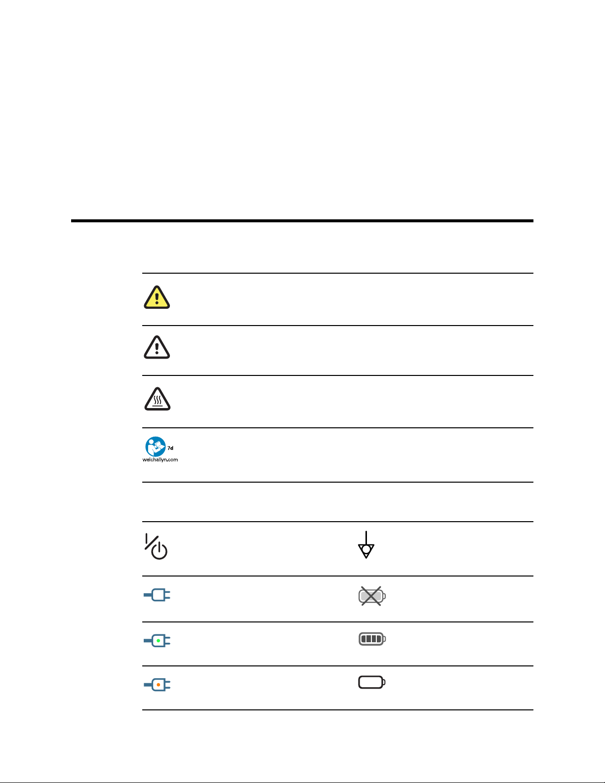
WARNING Hot surface. Do not touch.
Follow the operating instructions/directions for use (DFU) — mandatory action.
A copy of the DFU is available on this website.
A printed copy of the DFU can be ordered from Welch Allyn for delivery within 7 days.
Power on/Display power-saving Equipotential terminal
(on the display) monitor is plugged
into Alternating Current power
Battery absent or faulty
(on the monitor, green indicator)
Alternating Current power present,
battery fully charged
(on the monitor, amber indicator)
Alternating Current power present,
battery is charging
Battery charge level
Battery cover
Page 10
4
Symbols Welch Allyn Connex® Vital Signs Monitor 6000 Series™
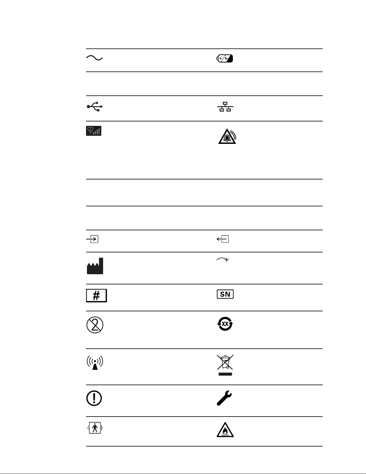
Alternating Current (AC) Rechargeable battery
Connectivity symbols
USB Ethernet RJ-45
Wireless signal strength
• Best (4 bars)
• Good (3 bars)
• Fair (2 bars)
• Weak (1 bar)
• No signal (no bars)
• No connection (blank)
Connected to central station Disconnected from central station
Miscellaneous symbols
CO2 sampling input CO2 sampling output/exhaust
Manufacturer Limited rotation/Turn completely to
Reorder number Serial number
Nurse call
right
Do not reuse China RoHS markings for control of
pollution caused by electronic
information products. XX indicates
Environmentally Friendly Use
Period in years.
Nonionizing electromagnetic
radiation
Restrictions for use of wireless
device in Europe. European
Community's Class 2 radio
equipment.
Defibrillation-proof Type BF applied
parts
Recycle the product separate from
other disposables
Call for maintenance
Do not expose to open flame
Page 11

Directions for use Symbols 5
Altitude range Not for injection
Transport and storage temperature
range
Authorized Representative of the
European Community
Page 12

6
Symbols Welch Allyn Connex® Vital Signs Monitor 6000 Series™
Page 13
Screen elements
Global navigation, controls, and indicators
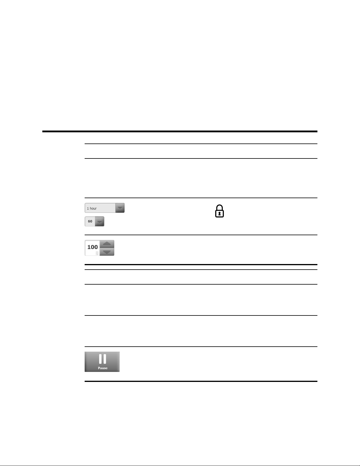
Select option Process indicator for
7
activities like acquiring
measurements and
connecting to a central
station
Select item from list Display lock/unlock
Increase or decrease value
Monitoring and connectivity
Connect to the central station
and retain patient data
(Monitor tab)
Connected to the central
station (Device Status area)
Temporarily pause continuous
monitoring but retain patient
data
Disconnect from the central
station but continue
monitoring and retain patient
data (Monitor tab)
Disconnected from the
central station (Device Status
area)
End continuous monitoring
session for current patient
and clear patient data
Page 14
8
Screen elements Welch Allyn Connex® Vital Signs Monitor 6000 Series™
NIBP
NIBP start NIBP stop
Intervals status indicators NIBP view toggle
Temperature
Temperature site control Direct mode selector
SpO2 and Pulse rate
Pulse amplitude bar SatSeconds timer (Nellcor
SpO2 view toggle Response mode selector (Fast
Pulse rate (in beats per
minute)
Total hemoglobin (SpHb)
SpHb view toggle Averaging mode selector
Capnography (CO2)
feature only)
mode selected)
(Long mode selected)
CO2 pump start CO2 pump stop
Page 15

Directions for use Screen elements 9
Capnography (CO2)
etCO2 view toggle IPI view toggle
IPI graphic indicators
RRa
Respiration indicator Averaging mode selector
(Fast mode selected)
Patient movement
Manual parameters
Bed mode Bed exit
Patient turn indicator and
timer
Patient turn indicator (Review
tab)
Bed exit (Review tab)
Exit sensitivity indicator
Manual parameter selector
Page 16
10
Screen elements Welch Allyn Connex® Vital Signs Monitor 6000 Series™
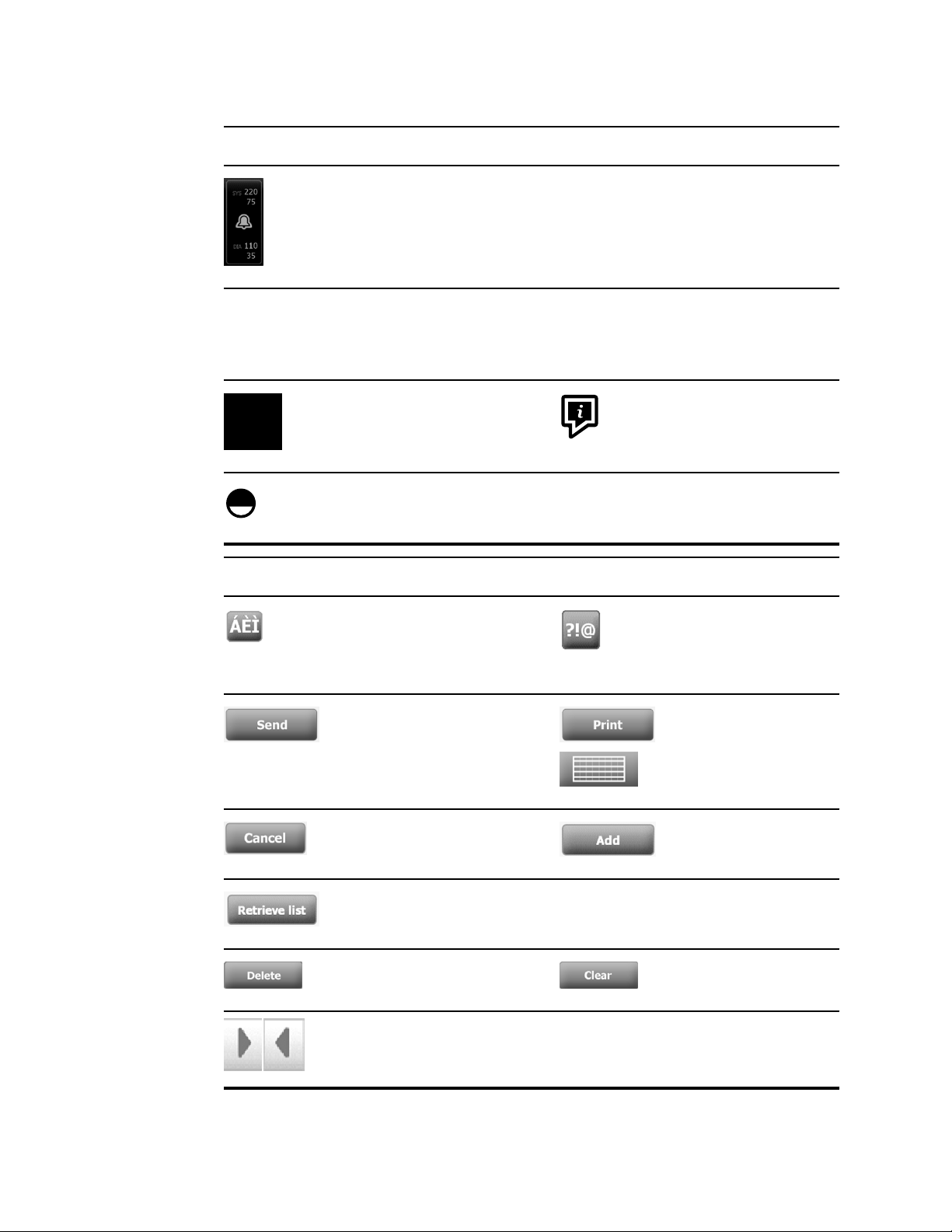
Alarm and information messages
Alarm limit control
Multiple alarms toggle Alarm audio paused
Alarm active Information message
Patient Rest Mode
Patient data management
Diacritical marks key
(available for languages that
use diacritical marks;
appearance differs based on
language)
Alarm On/Off toggle
Symbols key
Send patient data Print patient data/patient
trend data
Cancel action Add patient identifiers
Retrieve patient list from the
network
Delete patient from List tab Clear patient context from
Forward or backward in
Review tab
Select patient from List tab
Summary tab
Proceed to the next field to
input patient information
Page 17
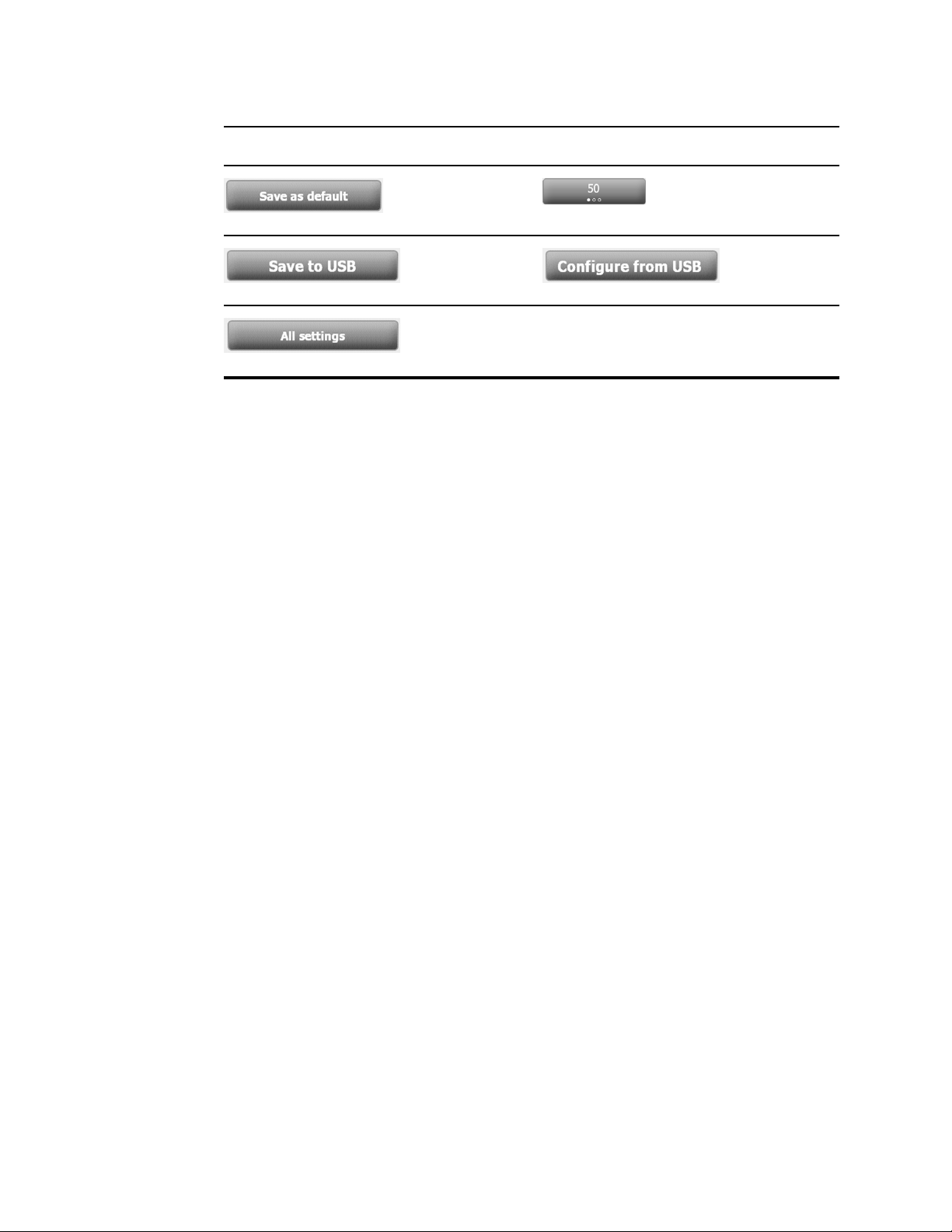
Directions for use Screen elements 11
Settings
Save configuration
settings
Save to USB flash
drive
Restore factory
default settings
Select state or view
Configure from USB
flash drive
Close Advanced
settings
Page 18

12
Screen elements Welch Allyn Connex® Vital Signs Monitor 6000 Series™
Page 19

About warnings and cautions
Warning and caution statements can appear on the monitor, on the packaging, on the
shipping container, or in this document.
The monitor is safe for patients and clinicians when used in accordance with the
instructions and the warning and caution statements presented in this manual.
Before using the monitor, you must familiarize yourself with all warnings and cautions,
with the steps to power up the monitor, and with the sections of this directions for use
that pertain to your use of the monitor. In addition to reviewing the general warnings and
cautions presented in the next section, you must also review the more specific warnings
and cautions appear throughout the manual in conjunction with setup/startup, device
operation, patient monitoring, and maintenance tasks.
• Failure to understand and observe any warning statement in this manual could lead
to patient injury, illness, or death.
• Failure to understand and observe any caution statement in this manual could lead to
damage to the equipment or other property, or loss of patient data.
13
General warnings and cautions
WARNING Many environmental variables, including patient physiology and
clinical application, can affect the accuracy and performance of the monitor.
Therefore, you must verify all vital signs information before treating the
patient. If there is any question about the accuracy of a measurement,
verify the measurement using another clinically accepted method.
WARNING Alarm limits are patient-specific. For alarms to function
properly, you must set or verify alarm limits appropriate for each patient.
Each time the monitor is powered on, you must check that the alarm
settings are appropriate for your patient before you start monitoring.
WARNING The monitor is not intended for use during patient transport
outside of the medical facility. Do not use the monitor to take
measurements on any patient in transit.
WARNING Do not use the monitor as an apnea monitor. Neither the VSM
6000 series monitors, nor any of the integrated or accessory sensor
systems used in conjunction with the VSM 6000 series monitors, are
intended for use in apnea monitoring.
Page 20

14
About warnings and cautions Welch Allyn Connex® Vital Signs Monitor 6000 Series™
WARNING Use only Welch Allyn approved accessories, and use them
according to the manufacturer’s directions for use. Using unapproved
accessories with the monitor can affect patient and operator safety and can
compromise product performance and accuracy.
WARNING Inaccurate measurement risk. Do not connect more than one
patient to a monitor.
WARNING Inaccurate measurement risk. Dust and particle ingress can
affect the accuracy of blood pressure measurements. Use the monitor in
clean environments to ensure measurement accuracy. If you notice dust or
lint build-up on the monitor's vent openings, have the monitor inspected
and cleaned by a qualified service technician.
WARNING Inaccurate measurement risk. Liquids and excessive moisture
can damage patient sensors and cause them to perform inaccurately or fail.
WARNING Patient harm risk. Always remove sensors from patients and
disconnect them completely from monitors before bathing.
WARNING Liquids can damage electronics inside the monitor. Prevent
liquids from spilling on the monitor.
If liquids are spilled on the monitor:
1. Power down the monitor.
2. Disconnect the power plug.
3. Remove battery pack from the monitor.
4. Dry off excess liquid from the monitor.
Note If liquids possibly entered the monitor, remove the monitor
from use until it has been properly dried, inspected, and
tested by qualified service personnel.
5. Reinstall battery pack.
6. Power on the monitor and verify that the monitor functions normally before
using it.
If liquids enter the printer housing:
1. Power down the monitor.
2. Disconnect the power plug.
3. Remove battery pack from the monitor.
4. Remove and discard the paper roll.
5. Clean and dry the inside of the printer housing.
Note The printer housing has a drain tube that directs liquids down
and out the bottom of the monitor. If liquids possibly entered
other openings in the monitor, remove the monitor from use
until it has been properly dried, inspected, and tested by
qualified service personnel.
6. Install a new roll of paper.
7. Power on the monitor and verify that the monitor functions normally before
using it.
Page 21

Directions for use About warnings and cautions 15
WARNING Safety risk and potential shock hazard. Cords, cables, and
accessories damaged from prior misuse can affect patient and operator
safety. Inspect all cords, cables, and accessories for strain relief wear,
fraying, or other damage according to the recommendations presented in
the Maintenance and service section of this manual. Replace as necessary.
Inspect the AC cord for exposed copper before touching the cord. Unplug
the AC cord only by pulling on the plug, never the cord. Never lift the
monitor by the power cord or patient connections.
WARNING Fire and explosion hazard. Do not operate the monitor in the
presence of a flammable anesthetic mixture with air, oxygen, or nitrous
oxide; in oxygen-enriched environments; or in any other potentially
explosive environment.
WARNING Fire and shock hazard. Only connect LAN cables contained
within the perimeter of a single building. Conductive LAN cables spanning
multiple buildings may introduce fire or shock hazards unless they are fitted
with fiber optic cables, lightning arrestors, or other applicable safety
features.
WARNING The monitor may not function properly if dropped or damaged.
Protect it from severe impact and shock. Do not use the monitor if you
notice any signs of damage. Qualified service personnel must check any
monitor that is dropped or damaged for proper operation before putting the
monitor back into use.
WARNING Defective batteries can damage the monitor. If the battery
shows any signs of damage or cracking, it must be replaced immediately
and only with a battery approved by Welch Allyn.
WARNING Improper disposal of batteries may create an explosion or
contamination hazard. Never dispose of batteries in refuse containers.
Always recycle batteries according to local regulations.
WARNING Electric shock hazard. Do not open the monitor or attempt
repairs. The monitor has no user-serviceable internal parts. Only perform
routine cleaning and maintenance procedures specifically described in this
manual. Inspection and servicing of internal parts shall only be performed
by qualified service personnel.
WARNING Inaccurate measurement risk. Do not expose to temperatures
higher than 122º F (50º C).
WARNING Inaccurate measurement risk. Do not use the monitor on
patients who are on heart-lung machines.
WARNING Inaccurate measurement risk. If using patient sensors during
full body irradiation, keep the sensor out of the irradiation field. If the
sensor is exposed to the irradiation, the reading might be inaccurate or the
monitor might read zero during the active irradiation period.
WARNING Inaccurate measurement risk. Do not use the monitor on
patients who are experiencing convulsions or tremors.
WARNING Use the monitor only as described in this directions for use. Do
not use the monitor on patients as described in the Contraindications.
Page 22

16
About warnings and cautions Welch Allyn Connex® Vital Signs Monitor 6000 Series™
WARNING Personal/patient injury risk. Wall-mounted equipment and
accessories must be installed in accordance with accompanying
instructions. Improper installation can result in the monitor falling off the
wall and injuring someone. Welch Allyn is not responsible for the integrity
of any installation not performed by authorized Welch Allyn service
personnel. Contact an authorized Welch Allyn service representative or
other qualified service personnel to ensure professional installation for
safety and reliability of any mounting accessory.
WARNING Do not place the monitor in any position that might cause it to
fall on the patient.
WARNING Welch Allyn is not responsible for the integrity of a facility's
power. If the integrity of a facility's power or protective earth conductor is
in doubt, always operate the monitor on battery power alone when it is
attached to a patient.
WARNING Avoid continuously monitoring a patient when the device is
operating on battery power. If only battery power is available, you must
remain in the room with any patient whose vital signs are being monitored
continuously. Actively monitor both patient and battery status to ensure
patient safety.
WARNING Patient harm and equipment damage risk. Carefully route
patient cabling to reduce the possibility of patient entanglement or
strangulation. When transporting the monitor on a mobile stand, properly
secure all patient cables and cords to keep them clear of the wheels and to
minimize trip hazards.
WARNING For operator and patient safety, peripheral equipment and
accessories that can come in direct patient contact must comply with all
applicable safety, EMC, and regulatory requirements.
WARNING All signal input and output (I/O) connectors are intended for
connection of only devices complying with IEC 60601-1, or other IEC
standards (for example, IEC 60950), as applicable to the monitor.
Connecting additional devices to the monitor may increase chassis or
patient leakage currents. To maintain operator and patient safety, consider
the requirements of IEC 60601-1-1. Measure the leakage currents to
confirm that no electric shock hazard exists.
WARNING Equipment failure and patient harm risk. Do not cover the air
intake or exhaust vents on the rear and base of the monitor. Covering
these vents could cause overheating of the monitor or muffling of alarms.
WARNING This equipment is not suitable for use in the presence of
electro-surgery.
WARNING Cross-contamination or nosocomial infection risk. Clean and
disinfect the monitor on a routine basis according to your facility's protocols
and standards or local regulations. Thorough hand-washing before and after
contact with patients greatly reduces the risk of cross-contamination and
nosocomial infection.
WARNING For patient safety, do not use the monitor or any accessory
during MRI scanning. Induced current could cause burns.
Page 23
Directions for use About warnings and cautions 17
WARNING When the monitor is not conected to a secondary alarm
system during continuous monitoring, check the monitor regularly to
receive patient data, alarms, and alerts.
WARNING Patient safety risk. The EarlySense system is not intended for
high-risk patients in coronary or respiratory distress who require continuous
monitoring of heart function or CO2. For these patients, the most reliable
method of patient monitoring involves close personal surveillance and/or
equipment suited to that type of monitoring.
CAUTION United States Federal law restricts this monitor to sale,
distribution, or use by or on the order of a physician or licensed healthcare
professional.
CAUTION Electromagnetic interference risk. The monitor complies with
applicable domestic and international standards for electromagnetic
interference. These standards are intended to minimize medical equipment
electromagnetic interference. Although this monitor is not expected to
present problems to other compliant equipment or be affected by other
compliant devices, interference issues still may occur. As a precaution,
avoid using the monitor in close proximity to other equipment. In the event
that equipment interference is observed, relocate the equipment as
necessary or consult manufacturer's directions for use.
CAUTION Use only a Class I (grounded) AC power supply cord for
powering this monitor.
CAUTION Do not use a long press of to power down the monitor
when it is functioning normally. You will lose patient data and configuration
settings.
CAUTION Never move the monitor or mobile stand by pulling on any of
the cords as this may cause the monitor to tip over or may damage the
cord. Never pull on the power cord when removing it from the power
outlet. When disconnecting the power cord, always grasp the attachment
plug and not the cord. Keep the cord away from liquids, heat, and sharp
edges. Replace the power cord if the strain relief or cord insulation is
damaged or begins to separate from the attachment plug.
CAUTION Use only the Welch Allyn USB client cable to connect a laptop
computer to the USB client port. Any laptop connected to the monitor must
be running on a battery, a 60601-1-compliant power supply, or a 60601-1compliant isolation transformer. While monitoring a patient, you can only
charge the laptop battery if it is connected to 60601-1-compliant, isolated
AC power.
CAUTION If the touchscreen is not responding properly, refer to the
troubleshooting section. If the problem cannot be resolved, discontinue use
of the monitor and contact an authorized Welch Allyn service center or
qualified service personnel.
CAUTION Verify patient identity on the monitor after manual or barcode
entry and before printing or transferring patient records.
CAUTION Keep the monitor outside of MRI suites and any areas marked
for high magnetic or electric field strength.
Page 24

18
About warnings and cautions Welch Allyn Connex® Vital Signs Monitor 6000 Series™
Page 25
Physical design
The monitor is available in two sizes: standard and extended. The primary difference
between these models is the number of parameters they support.
Note Your monitor, based on size or configuration, might not contain all
parameters or features illustrated in this section.
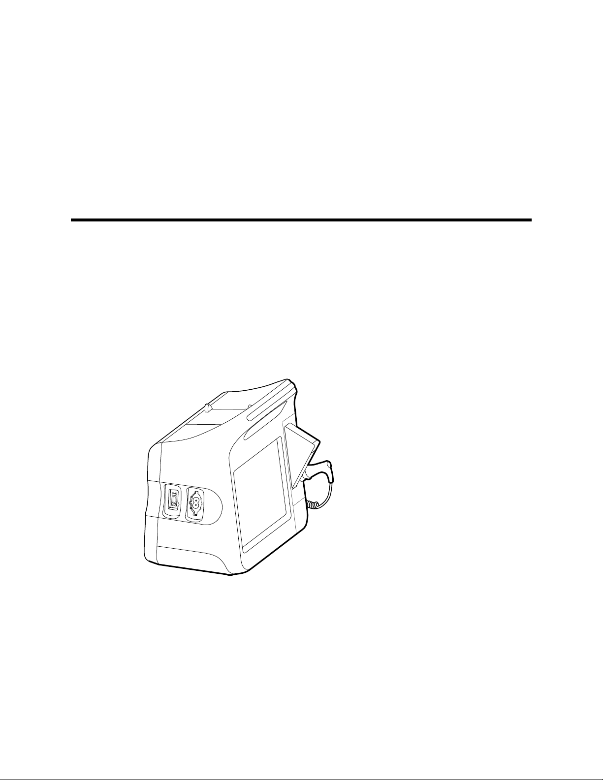
In a standard monitor, up to two parameter modules are installed on the left side. You
can tell which modules are installed based on the connectors visible on the outside of
the device. The following image shows a standard monitor with pulse-oximetry and
blood-pressure modules.
19
Standard monitor left side
Page 26
20
Physical design Welch Allyn Connex® Vital Signs Monitor 6000 Series™
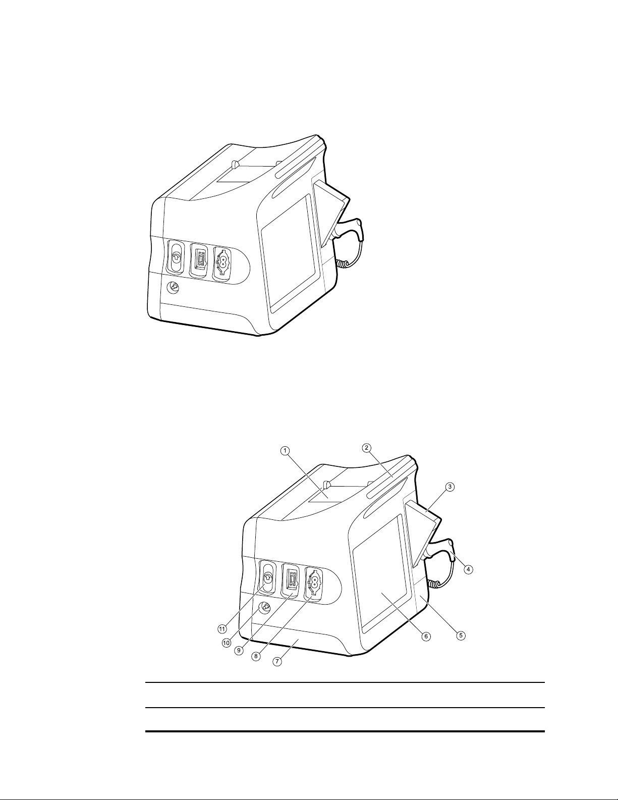
The extended version can have a maximum of three modules (such as CO2, pulse
oximetry, and blood pressure) on the left side.
Extended monitor left side
Equipment setup and basic monitor functions are the same for both models, unless
otherwise noted in the directions for use.
Controls, indicators, and connectors
The following diagrams show a full-featured monitor. Your monitor, based on size or
configuration, might not contain all of these features.
No. Feature Description
1 Printer Printer provides a printout of patient and device information.
Page 27
Directions for use Physical design 21
No. Feature Description
2 Light bar Provides a visual alarm with red and amber LEDs.
3 Thermometry Temperature probe cover box.
4 Thermometry Temperature probe.
5 Thermometry (connector behind cover) Secures the probe connection to the monitor.
6 LCD screen 1024 x 600 pixels color touchscreen provides a graphical user
interface.
7 Battery compartment (behind cover) Houses the lithium-ion battery.
8 Blood pressure Supports dual-lumen or single-lumen hoses.
9 Pulse oximetry
10 CO2 CO2 sampling exhaust port.
11 CO2 CO2 sampling input connector (behind cover).
Nellcor or Masimo rainbow SET module.
The Nellcor module measures SpO2 and pulse rate.
The Masimo module measures SpO2, pulse rate, SpHb, and RRa.
Note
Note
SpHb and RRa are optional parameters.
Monitors configured with RRa cannot be
configured with CO2.
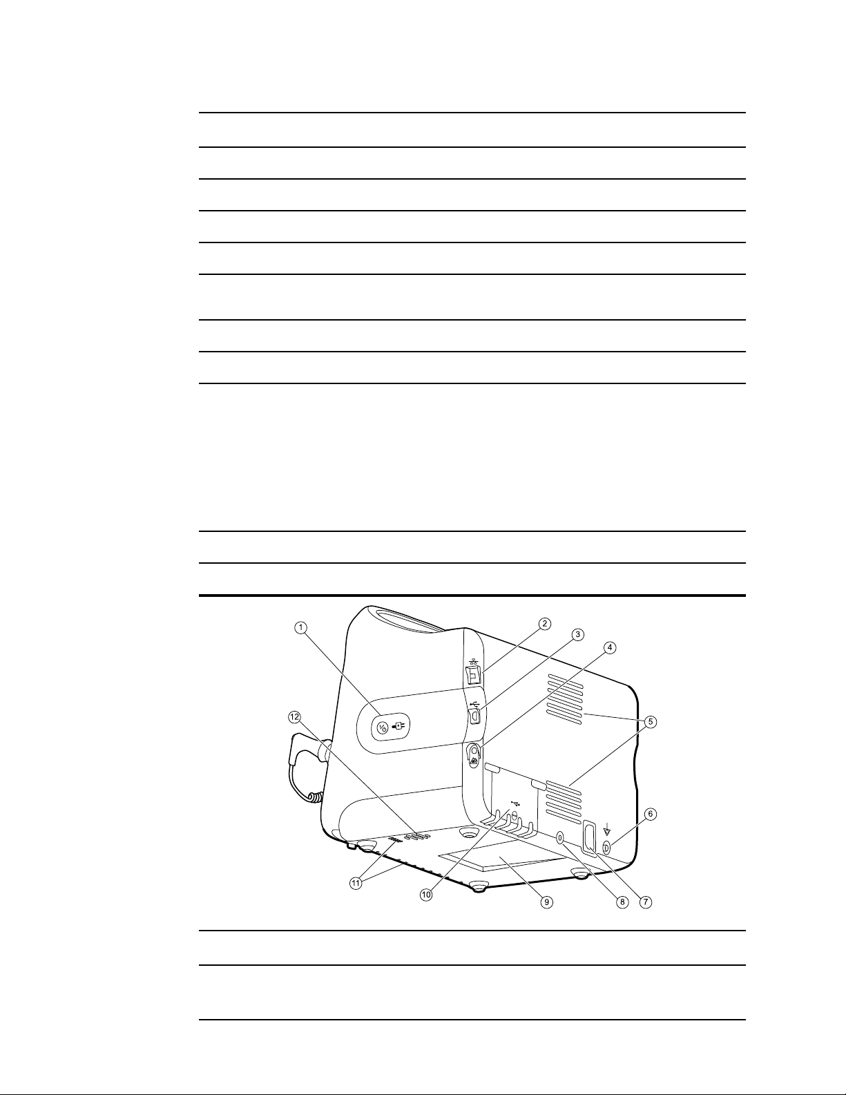
No. Feature Description
1 Power switch and LED Power-on/Display power-saving button.
The LED indicates the charging status when the monitor is
connected to AC power:
Page 28

22
Physical design Welch Allyn Connex® Vital Signs Monitor 6000 Series™
No. Feature Description
• Green: The battery is charged.
• Amber: The battery is charging.
2 Ethernet RJ-45 Provides a hardwired connection to the computer network.
3 USB client Provides a connection to an external computer for testing and
software upgrades.
4 Nurse call Provides a connection to the hospital nurse call system. (Not
available on the 6300 model.)
5 Fan exhaust
6 Ground lug (equipotential terminal) Provided for electrical safety testing and as a means for
connection of a potential-equalization conductor.
7 Power connection Provides an external AC power connection.
8 Mobile stand mounting hardware Secures the mounting plate to the monitor.
9 Recess for mounting plate Secures the monitor when the monitor is mounted on the mobile
stand or wall.
10 USB connector door Provides access to host USB connections for optional
accessories.
11 Fan intake
12 Speaker Provides tones. A piezo beeper inside the monitor provides
backup.
Page 29
Setup
Supplies and accessories
For a list of all approved supplies and accessories, see Approved accessories in the
Appendix.
Insert the battery
23
This procedure applies to first-time setup of the monitor.
WARNING Risk of fire, explosion, and burns. Do not short-circuit, crush,
incinerate, or disassemble the battery pack.
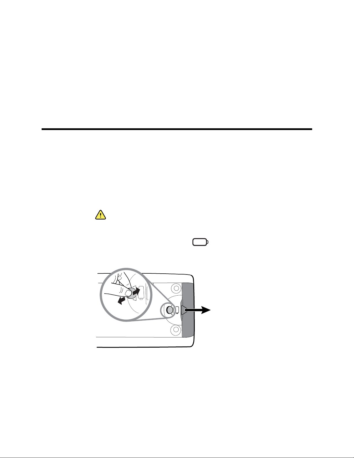
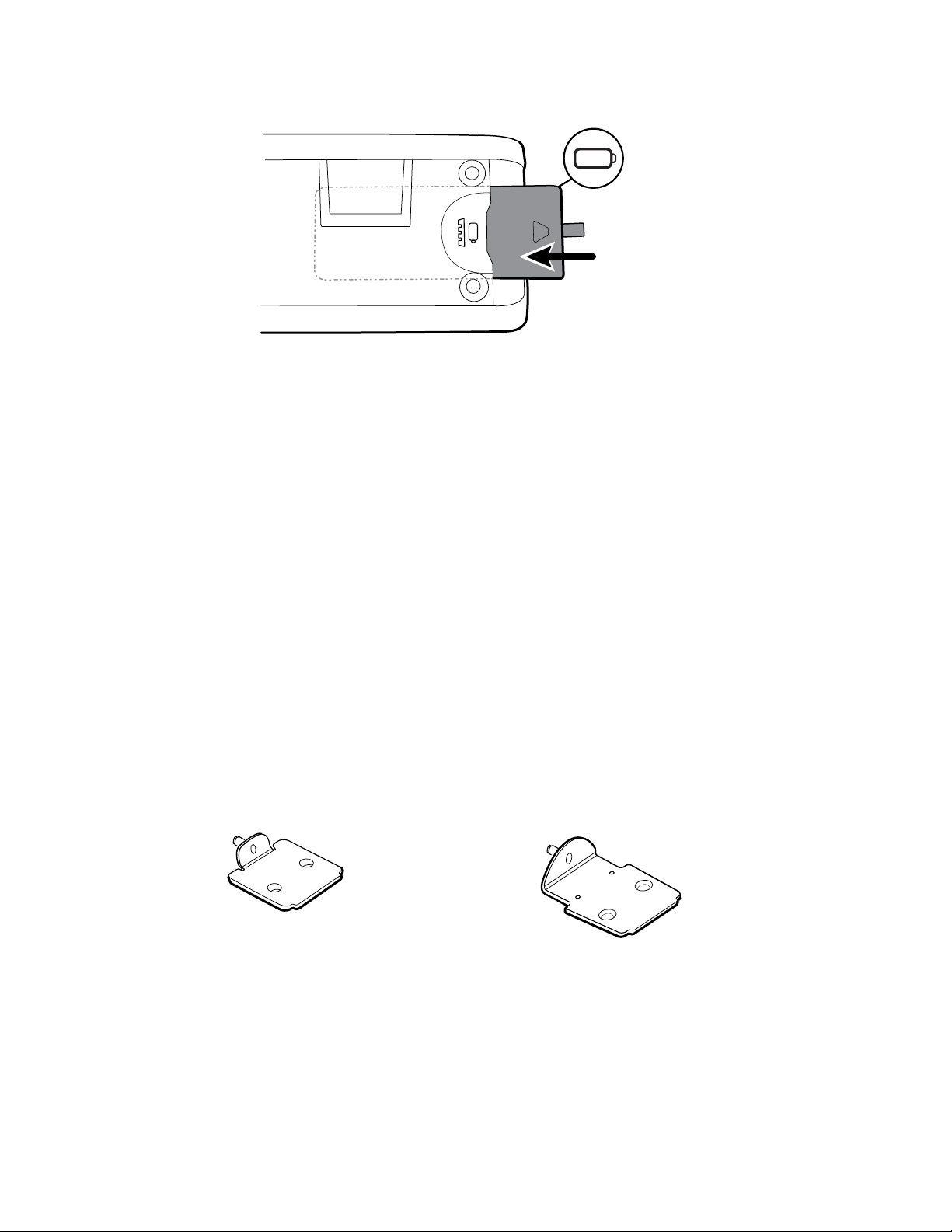
1. Turn the monitor upside down to access the battery cover.
2. Locate the battery cover, indicated by
3. Insert a coin into the slot and push to open. Choose a coin that fits comfortably into
the slot.
4. Slide in the battery.
.
Page 30
24
Setup Welch Allyn Connex® Vital Signs Monitor 6000 Series™
Note Do not remove the tab label from the battery. This tab helps
you remove the battery from the compartment when you
need to replace it.
5. Replace the battery cover by inserting one end into the notched access and then
pressing firmly on the opposite end.
Note New batteries are only 30 percent charged. Therefore, connect the monitor
to AC power immediately after inserting a new battery.
Mount the monitor
You can install the monitor on a mobile stand or on an interior wall equipped with a
Welch Allyn-approved wall-mount fixture.
Check the mounting bracket
Before you mount the monitor, make sure the stand or wall-mount fixture has the
mounting bracket designed for your monitor. Monitors with a standard housing require a
small bracket. Monitors with an extended housing require a large bracket.
Small bracket for standard housing Large bracket for extended housing
Note If your monitor has an extended housing but the small bracket is installed
on your stand or wall-mount fixture, you must replace the small bracket
with the large bracket. Follow the steps presented in the Mounting Bracket
Replacement Install Guide shipped with the large bracket, and then
proceed to mount the monitor.
Page 31

Directions for use Setup 25
Mount the monitor on a stand
1. Align the monitor on the mounting bracket in the center of the stand tray. Slide the
monitor into place, catching the bracket in the guides on the bottom of the monitor.
2. Ensure that the monitor is properly seated on the bracket. If you can raise either side
of the monitor off the stand, it is not seated properly. Repeat step 1 until the monitor
is mounted correctly.
3. Tighten the screw on the bracket into the screw hole on the back of the monitor.
Mount the monitor on the wall
For mounting instructions, see the wall mount manufacturer's directions for use.
Attach the probe well
1. Align the probe well with the tabs facing up and down and insert the probe well into
the temperature module.
The probe well snaps into place when it is fully seated.
2. Insert the temperature probe into the probe well.
Page 32

26
Setup Welch Allyn Connex® Vital Signs Monitor 6000 Series™
Attach the temperature probe
CAUTION The temperature module only operates with the probe well
properly in place.
1. Remove the cover of the temperature module by pressing the tab on the bottom and
sliding the cover to the right. The cover is located at the bottom-right of the monitor,
below the probe well.
2. Hold the temperature probe cable connector with the spring tab on the right and
insert it into the probe port of the temperature module.
3. Push it into place until it clicks.
4. Reattach the cover. Use the alignment tab and slide the cover to the left to click it
back into place.
Remove the temperature probe and well
Follow these steps to disconnect the probe cable and remove the probe well.
1. Remove the cover of the temperature module by pressing the tab on the bottom and
sliding the cover to the right. The cover is located at the bottom-right of the monitor,
below the probe well.
Page 33

Directions for use Setup 27
2. Depress the spring tab on the temperature probe cable connector and withdraw it
from the probe port.
3. Reattach the cover. Use the alignment tab and slide the cover to the left to click it
back into place.
Grasp the probe well and pull it up to remove it from the monitor.
Connect the NIBP hose
1. Place your thumb and forefinger on the hose connector and squeeze the side tabs.
2. Align the hose connector with the hose connector port on the side of the monitor.
3. Insert the hose connector, pressing firmly until it clicks into place.
Disconnect the NIBP hose
1. Place your thumb and forefinger on the hose connector.
Note Always grasp the hose by the connector. Do not pull on the
hose itself.
2. Squeeze the side tabs until the connector releases.
3. Pull the connector away from the connector port.
Connect the SpO2 cable or the SpO2/RRa dual cable
WARNING Patient injury risk. Do not use a damaged sensor or pulse
oximetry cable or a sensor with exposed electrical or optical components.
Follow these steps to connect the SpO2 cable or the SpO2/RRa dual cable to the SpO2
port on the monitor. The location of the port on your monitor might differ from that
shown in the images below.
Note For monitors configured with SpHb, the sensor used to monitor SpHb also
measures SpO2.
Connect the SpO2 cable
1. Place your thumb and forefinger on the cable connector and squeeze the side tabs.
Page 34

Setup Welch Allyn Connex® Vital Signs Monitor 6000 Series™
28
2. Align the cable connector with the cable connector port.
3. Insert the cable connector, pressing firmly until it clicks into place.
Connect the SpO2/RRa dual cable
Note Monitors configured to measure acoustic respiration (RRa) require a dual
cable as shown below. The dual cable has two ports, one for the SpO2
cable and the other for the RRa cable.
1. Connect the dual cable to the device as shown in the preceding steps. (The
connector is the same as for the standard SpO2 cable.)
2. Connect the SpO2 cable to the Pulse CO-Oximetry port (the larger of the two ports
with the red background).
3. Attach the RRa patient cable to the Acoustic Monitoring port (the smaller of the two
ports with no colored background). See the dual cable manufacturer’s directions for
use for more information.
Page 35

Directions for use Setup 29
Note Labels appear on both the top and bottom of the dual connector as well as
on the patient cables to help ensure proper connection of the patient
cables to the dual cable.
Note Typically, a clinician will connect the single-use RRa sensor to the RRa
patient cable at the start of acoustic respiration monitoring. See the sensor
manufacturer’s directions for use for more information. Also see the
Acoustic Respiration rate (RRa) section of this directions for use.
Disconnect the SpO2 cable or the SpO2/RRa dual cable
1. Place your thumb and forefinger on the cable connector.
Note Always grasp the cable by the connector. Do not pull on the
cable itself.
2. Squeeze the side tabs until the connector releases.
3. Pull the connector away from the connector port.
Connect the patient movement cable
1. Align the EarlySense cable connector with one of the EarlySense ports on the right
side of the monitor.
2. Insert the cable connector until it clicks into place. Also check the stress relief
connector on the cable to ensure that both parts of the cable are tightly connected.
3. When you are ready to monitor a patient, position the bed sensor (sensing unit) as
follows:
• horizontally under the patient's mattress
• the top surface of the sensing unit facing the mattress
• the sensing unit under the patient's chest area
• the sensing unit cable extending toward the head of the bed
Page 36

Setup Welch Allyn Connex® Vital Signs Monitor 6000 Series™
30
Note Typically, a clinician will connect the bed sensor and cable at the start of
patient movement monitoring. See the Patient movement section of this
directions for use for more information.
Disconnect the patient movement sensor and cable
To disconnect the EarlySense bed sensor, pull the sensor cable connector out of the
cable connector port on the device.
Attach a USB accessory
CAUTION Accessories attached to this monitor must run on battery
power. Do not use any accessory's external power supply when it is
attached to the monitor.
1. On the rear of the monitor, loosen the screw on the USB door and open it.
Note On some monitor stands, the monitor mounting bracket
partially overlaps the USB door. If you observe this overlap,
loosen the screw on the monitor mounting bracket and shift
the monitor forward just enough on the bracket to open the
USB door, then slide the monitor back on the mounting
bracket.
2. Attach each accessory's USB cable into an unused USB port on the monitor. See the
accessory's directions for use for any special instructions.
CAUTION Connect cables in a manner that minimizes
entangling.
3. Close the door and tighten the screw.
Page 37

Directions for use Setup 31
Note If you loosened the monitor mounting bracket in order to
open the USB door, shift the monitor forward on the bracket
as you did in step 1, close the door, and then slide the
monitor back into its mounted position. Ensure that the
monitor is seated firmly on the bracket, then tighten the
screw on the bracket into the screw hole on the back of the
monitor. (See "Mount the monitor on a stand" in this section
for more detail.)
Note Some accessories require a license to enable them for use. These
accessories are packaged with an authorization code and instructions for
activating the license using the Welch Allyn Service Tool. For more
information, refer to the instructions and the service tool installation guide.
Detach a USB accessory
1. On the rear of the monitor, loosen the screw on the USB door and open it.
2. Detach the accessory's USB cable from USB port on the monitor.
3. Close the door and tighten the screw.
Insert a new roll of paper
The printer is located on the top of the monitor. Follow these steps to insert the roll of
printer paper:
1. Grasp the two tabs on the printer door and pull up to open.
2. Insert a new roll of paper.
Note The paper roll must be installed so that it unwinds from the
bottom of the roll, as illustrated. If the paper roll is not
installed correctly, the printer will not print properly.
3. Advance the end of the roll past the roller so that it extends past the printer door, as
shown.
Page 38

32
Setup Welch Allyn Connex® Vital Signs Monitor 6000 Series™
4. With one hand, pull lightly on the paper to take up any slack. With the other hand,
close the printer door by pushing it down and into place until it clicks.
Be certain that the paper does not catch in the printer door.
Connect AC power
You can use the monitor with AC or battery power (after fully charging the battery).
WARNING Shock hazard. Inspect the AC cord for exposed copper before
touching the cord.
CAUTION During continuous monitoring, keep the monitor connected to
AC power at all times. If only battery power is available, you must remain in
the room with any patient whose vital signs are being monitored
continuously. Actively monitor both patient and battery status to ensure
patient safety.
1. Insert the power cord into the AC power connector port on the back of the monitor.
2. Insert the power plug into an electrical outlet to power the monitor and to charge the
battery.
Disconnect AC power
Carefully grasp the power plug and disconnect it from the power outlet. To avoid
damaging the power cord, do not pull on the cord itself.
Page 39

Startup
Power
33
The device operates in one of two power states:
• Device powered on. The device is operating on battery power or AC power. You can
utilize the device's features, and the display is active.
• Sleep (Display power-saving) mode. The device is operating on battery or AC power,
but the display is off to conserve power. Settings for this mode can be changed in
the Display tab in Advanced settings.
Note Battery-powered accessories connected to the device
continue to charge while the device is in this mode and
connected to AC power.
The following actions will return the display to the active state:
• Touch the screen
• Remove the temperature probe from the probe well
• Attach the SpO2 sensor to a patient
• Attach a sampling line to a patient
•
Press
The following actions will return the display to the active state:
• Touch the screen
• Remove the temperature probe from the probe well
• Attach the SpO2 sensor to a patient
• Connect the patient movement cable and bed sensor (sensing unit) to the device
• Attach a sampling line to a patient
•
Press
Page 40

34
Startup Welch Allyn Connex® Vital Signs Monitor 6000 Series™
Power on/Display power-saving button
The Power on/Display power-saving button , located on the device housing, performs
the following functions:
• Powers up the device
• Opens an onscreen Power-down dialog with options to Power down, Sleep, or
Cancel (brief press)
• Sets the device into Display power-saving (Sleep) mode (brief press followed by 30
seconds of inactivity)
Note The device will not enter the Sleep (Display power-saving) mode while an
alarm condition is active or when NIBP intervals or continuous
measurements are in progress. The device also exits this mode if an alarm
occurs.
The LED in the center of the power plug symbol indicates the battery charging status:
• Green indicates that AC power is present and that the battery is fully charged.
• Amber indicates that AC power is present and that the battery is charging.
Power up the monitor
The monitor runs a brief diagnostic self-test each time it powers up.
WARNING Equipment failure risk. The monitor includes a fan that
circulates air through the device. If the fan does not run when you power
up the device, remove it from use and inform qualified service personnel
immediately. Do not use the monitor until the problem is corrected.
WARNING To ensure patient safety, listen for two audible indicators (a
piezo beeper and a speaker tone) and watch for visual alerts at power-up at
least once daily. Correct any system errors before using the monitor. In
addition to the audible indicators, the monitor LED light bar illuminates to
alert you of alarms. Amber indicates a low-level alarm. Flashing amber
indicates a medium-level alarm. Flashing red indicates a high-level alarm.
Page 41

Directions for use Startup 35
WARNING Always observe the monitor during power-up. If any display
fails to illuminate properly, or if a system fault code or message displays,
inform qualified service personnel immediately, or call your nearest Welch
Allyn Customer Service or Technical Support facility. Do not use the
monitor until the problem is corrected.
CAUTION Always use the monitor with an adequately charged and
properly functioning battery.
CAUTION During continuous monitoring, keep the monitor connected to
AC power at all times.
CAUTION Use only a Class I (grounded) AC power cord for powering this
monitor.
1. Press to power up the monitor.
Following a successful self-test, the monitor displays the Welch Allyn logo, the LED
light bar (located on the handle) flashes, and a power-up tone sounds. The startup
screen then appears with the following banner across the bottom.
Note If patient data was saved during the most recent power
down and the device was in the Continuous Monitoring
profile, a Confirm patient and location dialog appears with
the following options:
• Same patient and location
• Same patient, new location
• New patient
Note If "Allow profile change" is enabled in Advanced settings and
continuous sensors are attached to the device at startup, the
device powers up in the Continuous Monitoring profile,
overriding other default profile selections.
2. If the Confirm patient and location dialog appears, select the desired option and
touch OK.
If a system error is detected during startup, the monitor becomes inactive until you press
or until the monitor shuts down automatically. The monitor displays a system fault
message that contains a wrench icon and a system fault code to aid service
personnel and engineers in diagnosing the problem.
Power down the monitor
You can power down the device as follows: 1) by briefly pressing the power button on
the housing and then following the onscreen prompts, or 2) by using onscreen controls
alone. These methods help prevent the inadvertent clearing of patient information and
configuration settings you have changed and saved so that they are available at the next
startup.
Page 42

36
Startup Welch Allyn Connex® Vital Signs Monitor 6000 Series™
CAUTION Avoid using a long press of to power down the device
when it is functioning normally. You will lose patient data and configuration
settings.
CAUTION Software updates may be remotely installed when you attempt
to power down the device. A progress bar appears, along with an indication
of the update. Do not turn off the device during the update or the update
may not fully install.
Key term
Patient context Condition in which a patient ID and patient type have been
selected on a device.
Option 1. After the device is powered up, a brief press of the power button opens an
onscreen dialog with the following options:
• Power down. Device behavior varies based on the active profile, whether or not
patient trend data is stored, and whether or not patient context is established. See
the Notes in Option 2, step 3.
• Sleep. The Sleep button clears the display and puts the device into Display powersaving mode.
• Cancel. The Cancel button dismisses the dialog.
Touch Power down and complete the power-down procedure as described in Option 2,
steps 3 and 4.
Option 2. To use onscreen controls alone to power down the device, follow these steps:
1. Touch the Settings tab.
2. Touch the Device tab.
3. Touch Power down.
A Power-down options dialog appears.
Note If the monitor is in the Continuous Monitoring profile and
continuous patient measurement data has been stored with
patient context, the Power-down options dialog displays the
following options:
• Save patient data on the device
• Remove patient data from the device
Note If the monitor is in the Continuous Monitoring profile and
continuous measurement patient data has been stored
without patient context, the Power-down options dialog
displays the following options:
• Save patient data on the device with a temporary Patient ID
• Remove patient data from the device
4. Select the desired option and then touch Power down.
The Power-down options dialog
The buttons in this dialog produce varied effects, as noted below:
Page 43

Directions for use Startup 37
• Power down.
○
When the Continuous Monitoring profile is not active: The device performs a
complete software shutdown, and any patient context and patient measurement
data displayed onscreen are cleared.
○
When the Continuous Monitoring profile is active, but no trend data has been
stored: The device performs a complete software shutdown.
○
When the Continuous Monitoring profile is active and trend data has been
stored:
– If you opted to save patient data, existing patient context (if established) and
trend data are stored and can be re-established on the next power up.
– If you opted to save patient data but no patient context was established,
trend data is stored under a temporary ID and can be re-established on the
next power up.
– If you opted to remove patient data from the device, monitoring and patient
assignment end, and trend data on the device is deleted.
• Cancel. This button dismisses the dialog and returns you to the previous screen.
Note If your monitor is configured with a Braun thermometer, avoid powering
down the monitor between patient measurements to help maintain an
adequate charge to the Braun dock.
Reset the monitor
If the monitor stops functioning, you can press and hold for approximately 6
seconds to allow the hardware to completely cycle off and to reset the monitor
configuration settings to the last saved default power-up configuration. The button is
located on the side of the monitor.
CAUTION Do not use a long press of to power down the monitor
when it is functioning normally. You will lose patient data and configuration
settings.
Set the date and time
1. Touch the Settings tab.
2. Touch the Device tab.
3. Touch the Date/Time vertical tab.
4. To change the date and time values: Touch the up and down arrow keys or touch
and enter a value.
Repeat for each value you want to change.
Note The date and time stamps on saved patient measurements
will adjust in response to new date and time settings.
Enter clinician information
1. Go to the Clinician tab using one of these methods:
Page 44

38
Startup Welch Allyn Connex® Vital Signs Monitor 6000 Series™
• On the Home tab, touch the Clinician ID section of the Device Status area (top
left corner of the screen).
• Touch the Settings > Clinician tab.
2. To enter the clinician name, touch , located at the right of the text field, and
enter characters.
You can enter up to 32 characters for the clinician's first and last name. Enter only 1
character for the middle initial.
3. To enter the clinician ID, use one of these methods:
• Touch and enter the ID.
• Scan the clinician's barcode with a barcode scanner.
Note If "Require clinician ID match to save measurements" is
enabled in Advanced settings, a progress indicator appears in
the Device Status area as the device queries an external host
system for a matching ID.
• An unsuccessful query results in the message, "Unable to identify
clinician."
• A successful query results in clinician data replacing the progress
indicator according to preferences configured in Advanced settings.
4. If prompted, enter your system password in the Authentication pane.
5. Touch OK to save your entries and return to the Home tab.
Set the default configuration
1. Enter or adjust the settings you want to add or change on the device.
Note The new settings appear as they are completed but are
temporary until they are saved.
2. Touch the Settings tab.
3. Touch the Device tab.
4. Touch the Defaults vertical tab.
5. Touch Save as default.
6. Touch OK to confirm that you want to overwrite your previous settings and replace
them with your current settings in the default startup configuration. Or touch Cancel
to retain the previous settings.
The new settings are stored as the default startup settings once you restart the monitor.
Note To enable or disable this control, navigate to the Device tab in Advanced
settings and select or deselect Enable save as default. (This requires the
Advanced settings access code.)
Note If the device is connected to Connex CS, the date and time settings are
synchronized with the Connex CS settings.
Note The date and time stamps on saved patient measurements will adjust in
response to new date and time settings.
Page 45

Navigation
The monitor screen provides the interface that you use to complete your workflow. You
access the monitor's features by touching the screen.
Home tab
The Home tab includes the following areas:
39
Item Area
1 Device Status
2 Content
3 Navigation
Device Status area
The Device Status area, located at the top of the Home screen, displays the following
monitor information, from left to right:
• Clinician identification. The format can be a name, ID number, or icon. Touch this
area to navigate to the Clinician login.
• Device location.
Page 46

40
Navigation Welch Allyn Connex® Vital Signs Monitor 6000 Series™
• Time and date. Touch this area to navigate to date and time settings.
• Current profile. Touch this area to navigate to the Profiles vertical tab (on the Device
tab), which displays available profiles.
• Connection status (wired or wireless, and central station). The icons indicate which
connections, if any, are currently attempted or active.
Icon Connection type or indicator
Ethernet
USB
Wireless
Wireless signal strength
• Battery condition. Estimated battery capacity is displayed in hour(s):minute(s) format.
This area also provides interactive alarm and information messages, including a Demo
mode active indicator.
Battery status
The battery status indicator displays the state of the battery.
Attempting to connect to the central station
Connected to central station
Not connected to central station
Blank No connection
Touch this area to navigate to the Device tab, where you can power down the
device.
The battery status is represented by icons in the right corner of the Device Status area:
• The monitor is connected to a power outlet and the battery is charging or is fully
charged. The estimated charge rate is displayed as a percentage of capacity.
Page 47

Directions for use Navigation 41
• The monitor is not connected to a power outlet and is running on battery power. The
estimated charge time remaining is displayed in the hour(s):minute(s) format. Each
section of the battery status indicator represents a percentage of remaining charge.
Note When the battery switches from AC power to battery power,
no charge time is displayed while the device calculates the
remaining charge time.
• The monitor is connected to a power outlet but the battery does not maintain a
charge or has been removed.
When the battery is not being recharged and power becomes low, a very low-priority
alarm appears in the Device Status area.
Note Observe the remaining battery charge in the battery status indicator and
plug the monitor into a power outlet as soon as you are able.
If the very low-priority alarm is dismissed or if you take no action to charge the battery, a
high-priority alarm appears when battery power is critically low. Plug the monitor into a
power outlet immediately to prevent it from powering down.
Failure to plug in the monitor before the remaining charge runs out causes the monitor to
power down and lose all unsaved data.
Alarm and information messages
The Device Status area provides alarm and information messages that are either
temporary or exist as long as the condition to which the message applies remains. Alarm
or information messages may also include controls and/or behavior that you can use to
manage alarm and information messages.
When the monitor detects an alarm condition, an alarm message appears. When
multiple alarms occur, the device provides options to manually toggle or autoscroll
through a stack of messages. You can cycle through each alarm message in sequence of
priority by touching the multiple alarm toggle. Alternatively, the autoscroll option displays
messages in the stack for approximately 4 seconds. These messages are stacked in
order of priority: the monitor displays the highest priority messages first followed by
each successive alarm message in order of priority. After presenting the entire stack of
alarm messages, the autoscroll feature loops back to the top priority message and
repeats the entire stack unless specific alarms auto-dismiss or you reset or cancel
specific alarms. In both the manual toggle and autoscroll options, when multiple alarm
messages of the same priority exist at the same time, the device displays the most
recent of those alarm messages first.
Information messages instruct you to interact with the monitor in a specific way or
provide information that does not require action. You can dismiss an information
Page 48

Navigation Welch Allyn Connex® Vital Signs Monitor 6000 Series™
42
message by selecting the control associated with the message or waiting for the
message to time out. Information messages rank the lowest in priority.
When the monitor is operating in Demo mode, which requires access to Advanced
settings, the Device Status area displays an information message indicating that the
Demo mode is active, as shown below.
Any alarm messages that occur in Demo mode include a clear "DEMO MODE:" prefix as
well.
Content area
The Content area displays current vital sign measurements and patient identification. It
also provides relevant controls.
The Content area includes the following:
• A frame for each available parameter
• The Patient frame
• The Manual parameters frame (height, weight, pain, temperature, respiration, and
BMI, depending on configuration)
In the Triage, Spot Check, and Intervals Monitoring profiles, the Content area also
includes a Save button, which you use to manually save current measurements to the
Review tab. If your monitor is connected to an external system, you can send these
patient measurements to that external system as well. You can configure your monitor
to automatically send these measurements any time you press Save, or you can navigate
to the Review tab and then select specific records to send to the external system.
In the Continuous Monitoring profile, patient measurement data is automatically saved to
the Review tab. Consequently, there is no Save button on the Home tab. (A Pause
button appears in its place. See "Pause continuous monitoring (Pause mode)" in the
Connex CS section of this directions for use.) If the monitor is connected to the Connex
central station, the monitor automatically sends these patient measurements to the
central station as well.
Page 49

Directions for use Navigation 43
Navigation area
The Navigation area includes the following tabs:
• Home: Displays vital-sign measurements and provides shortcuts to several controls.
• Patients: Accesses the patient list, patient summary, and manual parameters.
• Alarms: Accesses global alarm response and settings controls, alarm limit settings
(available only in the Intervals Monitoring and Continuous Monitoring profiles), and
patient rest mode.
• Review: Prints, deletes, and sends patient data.
• Settings: Accesses device configuration settings.
To navigate to a tab, touch the tab in the Navigation area with the corresponding name.
The active tab is highlighted.
Display lock
The display lock prevents clinician input, which may be useful when cleaning the display.
Note The lock feature is not a security mechanism.
The display locks when any of the following occur:
• You touch Lock display now.
• No interaction with the monitor occurs for the period specified in the Display tab.
Use the Advanced tab to set or change the time it takes for the display to lock. (This
requires the Advanced settings access code.)
Lock the display
Follow these steps to touch the screen without activating the controls.
1. Touch the Settings tab.
2. Touch the Device tab.
3. Touch Lock display now.
The following occurs:
• The Home screen appears.
Page 50

44
Navigation Welch Allyn Connex® Vital Signs Monitor 6000 Series™
• A title bar with a lock icon ( ) replaces the Navigation area at the bottom of the
screen.
• Patient information no longer appears at the bottom left of the screen.
• All controls on the screen are locked, except for on the title bar. If you select
Unlock the display
On the locked screen, touch
The following occurs:
• Patient information appears in the Patient frame.
• The Navigation area appears.
• Home tab controls are available for use.
The display also unlocks when the following occur:
• An alarm condition.
• An externally initiated action, such as taking or stopping an NIBP measurement or
upgrading software.
• Connecting a sampling line.
any area of the screen other than , a message appears.
in the title bar (located at the bottom of the screen).
Page 51

Using the keypad, keyboard, and barcode scanner
Open the numeric keypad
45
Touch any field that includes the numeric keypad icon
The numeric keypad appears.
Numeric keypad
.
The numeric keypad includes the following components:
Component Name Description
Data field Displays the numbers you enter. The field name
appears above and the range of values you can
enter appears below this field.
Backspace key When touched, removes the rightmost number
from the data field.
Page 52

Using the keypad, keyboard, and barcode scanner Welch Allyn Connex® Vital Signs Monitor 6000 Series™
46
Component Name Description
Cancel button When touched, the numeric keypad disappears
and the selected number does not change.
OK button When touched, the numeric keypad disappears
and the entered number appears in the associated
frame or data field.
Enter a number
1. With the numeric keypad open, touch a number or numbers.
The value must be within the range that appears below the data field.
2. Touch OK.
• If the value is within the required range and format, the numeric keypad
disappears and the entered numbers replace the previous numbers.
• If the number is not within the required range and format, OK remains inactive
until you enter a valid number.
Close the numeric keypad
Touch one of the following:
• OK: Exits the numeric keypad and inserts the number.
• Cancel: Exits the numeric keypad without saving entered numbers.
Open the keyboard
Touch any field that includes the keyboard icon .
The keyboard appears.
Keyboard
The keyboard includes the following components:
Page 53

Directions for use Using the keypad, keyboard, and barcode scanner 47
Component Name Description
Data field Displays the characters you enter.
Note
Backspace key When touched, removes the rightmost
character from the data field.
Space bar When touched, enters a space in the data field.
Shift key When touched, enters the next letter as
uppercase.
Letters key When touched, returns to the primary keyboard
layout. The keyboard changes from normal
layout when you touch one of these:
• The symbols key
• The diacritical marks key
The keyboard can be
configured to mask character
entries and display them as
asterisks.
Symbols key When touched, the keyboard displays symbols.
The keyboard returns to its normal layout when
you touch one of these:
• Any symbol
• The letters key
• The symbols key
Note
Diacritical marks key
(appearance varies in
some languages)
When touched, the keyboard displays letters
with diacritical marks. The keyboard returns to
its normal layout when you touch one of these:
• Any letter
• The letters key
• The diacritical marks key
Note
Next button When touched, accepts the entry for the
current field, then clears the field to allow data
entry for the next field.
The symbols that display
match the selected
language.
This key appears only when
the selected language uses
diacritical marks.
Cancel button When touched, the keyboard disappears and
the content of the data field remains the same.
OK button When touched, the keyboard disappears and
the entered characters appear in the data field.
Page 54

48
Using the keypad, keyboard, and barcode scanner Welch Allyn Connex® Vital Signs Monitor 6000 Series™
Enter a letter or number
1. With the keyboard open, touch letters or numbers.
2. Do one of the following:
• Touch Next. This control accepts the entry for the current field, then clears the
data field to allow data entry in the next field.
• Touch OK. The keyboard disappears and the entered characters appear in the
data field.
Enter a symbol or special character
Note To return to the keyboard's normal layout, touch .
1. With the keyboard open, touch
Symbols and special characters for the selected language appear.
2. Touch the appropriate symbol or special character.
The keyboard returns to its normal layout.
Enter a diacritical mark
Note Keyboards with diacritical marks are available only for languages that use
diacritical marks.
Note To return to the keyboard's normal layout without saving changes, touch
.
Diacritical marks key Language(s)
.
None (Not applicable) Danish, English, Dutch, German, Italian
French
Finnish, Norwegian, Spanish, Swedish
Portuguese
Page 55

Directions for use Using the keypad, keyboard, and barcode scanner 49
Diacritical marks key Language(s)
Polish
Greek
1. With the keyboard open, touch the diacritical marks key. This key varies based on
the language, as noted above.
The keyboard displays diacritical marks for the selected language and therefore
varies from one language to another. On each diacritical marks keyboard, the letters
key in the top left corner returns you to the standard keyboard.
2. Touch a diacritical mark.
The keyboard returns to its normal layout.
Close the keyboard
Touch one of the following:
• Next: Accepts the entry for the current field, then clears the field to allow data
entry for the next field.
• OK: Exits the keyboard and inserts the data.
• Cancel: Exits the keyboard without saving entered data.
Use a barcode scanner
The monitor enables the scanning of patients’ and clinicians’ barcodes to enter ID
information. The barcode scanner supports linear and two-dimensional barcodes.
If you haven't done so already, attach the barcode scanner to the monitor. Use the
instructions to attach an accessory.
Note Refer to the manufacturer's directions for use to ensure that the scanner is
set to USB Com Emulation mode.
1. Remove the barcode scanner from its holder.
2. Hold the scanner approximately 6 inches (15.4 cm) from the barcode and squeeze
the trigger so that the light from the scanner appears on the barcode.
Once the scanner completes a successful barcode reading and any required queries
for a matching ID on the device or in an external host system, the ID appears in the
targeted area (Patient frame, data field, or Device Status area). See additional notes
below.
If the scanner has difficulty reading the barcode, slowly adjust the distance and the
angle between the scanner and the barcode while squeezing the scanner trigger. If it
continues to have difficulty, verify that the barcode is as flat as possible.
Page 56

50
Using the keypad, keyboard, and barcode scanner Welch Allyn Connex® Vital Signs Monitor 6000 Series™
Note You can scan a patient's barcode from the Home tab or the Summary tab.
The scanned ID appears in the Patient frame on the Home tab and in the
Patient ID field on the Summary tab.
Before you scan a barcode on the Summary tab, touch the keyboard icon in
the Patient ID field. To return to the Home tab and begin taking patient
measurements, touch OK.
Note If "Require patient ID match to save measurements" is enabled in Advanced
settings, a progress indicator appears onscreen as the device queries an
external host system or the device's Patient list for a matching ID.
• An unsuccessful query results in the message, "Unable to identify patient."
• A successful query results in patient data populating fields and appearing
onscreen according to preferences configured in Advanced settings.
Note If "Require clinician ID match to save measurements" is enabled in
Advanced settings, a progress indicator appears onscreen as the device
queries an external host system for a matching ID.
• An unsuccessful query results in the message, "Unable to identify clinician."
• A successful query results in clinician data replacing the progress indicator
according to preferences configured in Advanced settings.
Note Scanning a clinician ID while the Clinician ID pane is open places the
scanned ID into the Clinician ID section of the Device Status area. Touch
OK to return to the Home tab and to begin taking patient measurements.
Note Use the Advanced settings Data Management tab to change the
appearance of the Clinician ID if you do not want your ID to appear in the
Device Status area. (This requires the Advanced settings access code.)
However, this information is still retained in the monitor memory for recall,
printing, or to send measurements electronically to the network.
Page 57

Connex CS
Overview
A monitor can be used as standalone device or be networked to a central station
(Connex CS). This section describes communication between the monitor and the
central station.
Monitors communicate with the central station through hardwired Ethernet and wireless
networks. The diagram below shows monitors connected to the central station.
51
1. Wired monitors
(Ethernet
connection)
2. Wireless
monitors
3. Wireless access
point
4. Network
5. Central station
The central station provides centralized monitoring of connected monitors. This central
monitoring system supports the communication of continuously monitored and
intermittently acquired (episodic) data, patient vital-sign alarms, and technical equipment
alerts, as well as the review and printing of all stored data.
Communication between the monitor and the central station is bi-directional but varies
based on the active profile and selected advanced settings. In all profiles, for example,
episodic patient data can be saved and sent to the central station, but in the Continuous
Monitoring profile, patient vital-signs data streams to the central station automatically
when the monitor is connected to the central station. You can enable or disable
Page 58

Connex CS Welch Allyn Connex® Vital Signs Monitor 6000 Series™
52
automatic connection to the central station in Advanced settings. Furthermore, in all
profiles but Triage (see Note), you can add patients to a patient list on the monitor and
then send them to the central station, and you can also retrieve patient lists from a
central station. In the Intervals Monitoring and Spot Check profiles, retrieving the patient
list requires user action. In the Continuous Monitoring profile, the patient list on the
monitor updates automatically when the monitor is connected to the central station.
Note The Triage profile does not include a Patients tab and therefore does not
provide a patient list.
Once you assign a patient to a monitor and send this information to the central station,
you can edit patient information on the monitor as noted in the following table:
Editable patient information based on profile
and central station communication
Spot Check and Intervals profiles X X X X
Continuous Monitoring profile, communicating with
the central station
Continuous Monitoring profile, not communicating
with the central station
Note In many cases, changing patient information opens an onscreen dialog
If a monitor loses its connection to the central station, the device continues to monitor
the patient, display patient data, and generate alarms and messages. When connectivity
is restored, the monitor resumes sending vital-signs trends and episodic data.
Monitor tab
The Monitor tab provides the following controls related to continuous patient monitoring
at the device and the streaming of patient vital-signs data to a central station:
• End Monitoring – Stop continuous monitoring on the current patient and clear patient
• Pause – Pause continuous monitoring as well as alarms for a specified period and
• Change pause interval – Increase or decrease the pause interval in 15 minute
• Connect to central station – Manually connect to a central station and start or
• Disconnect from central station – Manually disconnect the device from a central
Patient ID Patient name Patient
location
X X
X X X
Patient type
asking you to confirm the action. These dialogs appear whenever the action
results in clearing patient measurement data or patient context.
data on the device.
retain patient data on the device.
increments up to 2 hours.
resume the streaming of patient vital-signs data when the device does not connect
automatically.
station yet continue monitoring the patient and retain patient vital-signs data on the
device. This control is only available after connecting to a central station.
The sections which follow provide instructions for using these controls.
Note This tab is visible only when the Continuous Monitoring profile is active. It
is not available in the Triage, Spot Check, or Intervals Monitoring profiles.
Page 59

Directions for use Connex CS 53
Note The Continuous Monitoring profile is available only on devices with a
Continuous Monitoring profile license.
Connect to the central station
To connect the monitor to a central station over a wireless or Ethernet network
connection while in the Continuous Monitoring profile, you must first enable the
Connect to CS option in Advanced setttings. When this control is enabled, the monitor
automatically attempts to connect to the central station and continues to do so until a
connection is achieved.
If the Continuous Monitoring profile is active but your device has been disconnected
from the central station (you will see the indicator in the Device Status area), you
can restore the connection manually.
1. Touch the Settings tab.
The Monitor tab appears.
2. Select
As the monitor attempts to connect to the central station, a appears in the
Device Status area until a connection is achieved. When the monitor connects to the
central station, the indicator appears.
The Connect to CS control described above only impacts the Continuous Monitoring
profile, but you can configure Intervals Monitoring and Spot Check profiles to
communicate with a central station as well in Advanced settings. In these configurations,
if either the Intervals Monitoring or Spot Check profile is active, your device connects to
the central station when you retrieve a patient list or load a patient's previously saved
records with a barcode scanner. In addition, you can send episodic data to the central
station when you touch Send on the Patient Review tab.
Connect to central station.
Disconnect from the central station
Disconnecting from the central station enables you to stop streaming data to the central
station yet continue monitoring your patient, retaining patient vital signs data on the
monitor. Select this option when you need to transport a patient yet continue monitoring
them.
1. Touch the Settings tab.
The Monitor tab appears.
2. Select
If reasons for disconnecting from the central station have been configured in Connex
CS, a Disconnect dialog appears with a list box of reasons.
3. Select a reason for disconnecting, if applicable, then touch OK.
The Home tab appears.
Disconnect from central station.
Page 60

Connex CS Welch Allyn Connex® Vital Signs Monitor 6000 Series™
54
Continuous patient monitoring
Your device must be configured with the Continuous Monitoring profile to perform
continuous patient monitoring.
Key terms
Patient context Condition in which a patient ID and patient type have been selected on a device.
Location context Condition in which a room or a room and bed have been selected on a device.
You have the option to continuously monitor patients on the device alone (primary
monitoring) or to stream continuous patient data to a central station as well (secondary
monitoring).
If Continuous Monitoring has been configured as the default profile, then the device
starts up in this profile. If the Continuous Monitoring profile is active, you can proceed
with an existing patient and/or location context, or you can assign a patient and location.
Activate the Continuous Monitoring profile
If the Continuous Monitoring profile is not active, follow these steps:
1. Touch the Settings tab.
2. Touch the Device tab.
The Profile vertical tab appears.
3. Select Continuous Monitoring.
When neither patient nor location context are established and no patient
measurements have been taken or saved, the Continuous Monitoring profile
immediately becomes active. If these conditions do not apply, proceed to step 4.
4. Using the conditions presented in boldface text, select and follow the steps below
that apply to your patient and the device.
a. When patient and/or location context are established but no patient
measurements have been taken or saved:
A confirmation dialog appears asking you to confirm the patient and/or location
context information or select a new patient. For example, if both patient and
location context have been established, the following options appear:
• Same patient, same location
• Same patient, different location
• New patient
Select the desired option and touch OK.
b. When patient and/or location context are established and patient
measurements have been taken or saved:
A confirmation dialog appears with the following message: "Changing to the
Continuous Monitoring profile deletes all measurement data from the device.
Continue anyway?"
1. Touch Yes to confirm or No to cancel the profile change.
Page 61

Directions for use Connex CS 55
Note Selecting No enables you to send captured vitals data on
the device before changing profiles. After you complete
that task, if applicable, repeat steps 1 to 3.
Another confirmation dialog appears asking you to confirm the patient and/or
location context information or select a new patient. For example, if both patient
and location context have been established, the following options appear:
• Same patient, same location
• Same patient, different location
• New patient
2. Select the desired option and touch OK.
The profile change immediately takes effect.
5. Touch the Home tab.
You can now start monitoring a patient in the Continuous Monitoring profile.
Pause continuous monitoring (Pause mode)
You can temporarily pause continuous monitoring and retain patient data on the device
when your patient needs to ambulate, use the restroom, or go off the unit for a test.
Note If a low-battery alarm occurs on the device, Pause mode is not available.
Note While in Pause mode, the device retains previously stored patient data, but
it does not display this data or store additional patient measurements until
you exit Pause mode.
1. Touch Pause on the Home tab.
A "Pause" dialog appears, indicating that you have paused continuous monitoring.
Controls on this screen provide options to resume or end monitoring. A countdown
timer displays the time remaining before continuous monitoring resumes.
Note You can configure the Pause Mode timeout in Advanced
settings.
2. To increase the pause interval, repeatedly touch the + symbol until the desired
length of time appears.
The pause interval is automatically applied.
Page 62

Connex CS Welch Allyn Connex® Vital Signs Monitor 6000 Series™
56
Resume continuous monitoring
You can resume continuous monitoring after a pause when patient sensors are
connected to a patient. The status of the pause timer determines your next step.
Pause time remaining
If the pause time limit has not expired (time remains on the countdown timer), resume
monitoring as follows:
1. Reconnect patient sensors to the patient as needed.
2. Touch Resume monitoring.
The Home tab appears and continuous monitoring resumes.
Pause time limit expired (patient sensors connected)
If the pause time limit has expired and you have already reconnected patient sensors to
the patient and/or the device, the Home tab appears and continuous monitoring
automatically resumes.
Pause time limit expired (patient sensors disconnected)
If the pause time limit runs out before you resume monitoring, the device exits Pause
mode, and alarms might occur.
Reconnect patient sensors to the patient and/or device and acknowledge alarm and
information messages as needed.
Continuous monitoring resumes.
End continuous monitoring
When you no longer need to monitor a patient continuously, follow these steps to end
monitoring:
1. Touch the Settings tab.
The Monitor tab appears.
2. Touch End monitoring.
An "End monitoring" dialog appears with the following options:
• New patient – Clears patient and location context and review data after you
remove patient sensors
• Power down – Clears patient and location context and review data, and powers
down the device
• Cancel – Retains patient data and returns to Home tab
3. Select the desired option.
Page 63

Directions for use Connex CS 57
Note After approximately 30 seconds of inactivity, the "End
monitoring" dialog disappears. If you do not respond to this
dialog and continuous monitoring is interrupted, the "Confirm
patient and location" dialog appears. You must respond to
this dialog before continuous monitoring resumes.
4. If you select New patient, follow the onscreen prompt to remove sensors from your
patient (and the device, if applicable), and then touch OK.
The Home tab appears.
Assign a patient and location
You can assign a patient and location after you have begun to monitor a patient's vital
signs.
When you start to continuously monitor a patient on a device that has no patient context,
the following information message appears in the Device Status area: "Assign patient
and location."
1. In the top right corner of the screen, touch Assign.
The List tab appears.
Note When the monitor is connected to a central station, the
monitor automatically retrieves the patient list when you
navigate to the Patients tab.
2. If you see your patient's name on the patient list, select that patient entry, and then
touch Select.
The Home tab appears with patient and/or location information filled in according to
your monitor's settings.
Note If patient name or location information is missing, the
monitor will prompt you to "Assign patient" or "Assign
location" until that information is complete. You can monitor
the patient without entering all of these details.
3. If your patient's name does not appear on the patient list, touch Add.
4. In the Patient pane, touch
Next to cycle through the patient data fields.
Note You can use a barcode scanner to enter a patient ID in the
Patient ID field. Touch
the barcode, and touch OK.
in a field and enter patient information. Touch
in the Patient ID field, scan
Note If "Require patient ID match to save measurements" is
enabled in Advanced settings, a progress indicator appears
onscreen as the device queries an external host system or
the device's Patient list for a matching ID.
• An unsuccessful query results in the message, "Unable to identify
patient."
• A successful query results in patient data populating fields and appearing
onscreen according to preferences configured in Advanced settings.
Page 64

58
Connex CS Welch Allyn Connex® Vital Signs Monitor 6000 Series™
5. In the Location pane, select an available room and bed from the list box.
Note The Location list only presents locations that are not already
assigned to a continuous monitoring device.
"No location assigned" appears in the list box until you select a room and bed.
6. Touch OK to return to the Home tab.
The information is saved.
Note You have the option to leave some fields blank on the Patient > Summary
tab. However, if patient name or location information is missing, the
monitor will prompt you to "Assign patient" or "Assign location" until that
information is complete. You can monitor the patient without entering all of
these details.
Page 65

Profiles
59
Profiles are variations of the Home tab. Each profile gives you access to a different set of
features. Choose the profile that best suits your needs.
The monitor offers multiple profiles—including Continuous Monitoring, Intervals
Monitoring, Spot Check, and Triage—based on the configuration and any upgrade
licenses you purchase.
Continuous Monitoring profile
The Continuous Monitoring profile is designed for continuous patient monitoring.
Monitors configured with Oridion Microstream Capnography provide continuous
monitoring of end-tidal CO2 (etCO2), fraction of inspired CO2 (FiCO2), respiration rate
(RR), pulse rate, and Integrated Pulmonary Index (IPI). Monitors configured with the
Nellcor pulse oximetry option provide continuous monitoring of oxygen saturation of
hemoglobin (SpO2) and pulse rate. Monitors configured with the Masimo rainbow SET
option may provide continuous monitoring of oxygen saturation of hemoglobin (SpO2),
total hemoglobin (SpHb or SpHbv), Acoustic Respiration (RRa), and pulse rate.
The Continuous Monitoring profile also enables you to take manual temperature or NIBP
readings, as well as use alarms and timed intervals.
The Continuous Monitoring profile also enables you to take manual temperature or NIBP
readings, to use alarms and timed intervals, and to use bi-directional controls to transmit
data between the monitor and a central station.
Note Patient data continuously streams to a central station only in the
Continuous Monitoring profile.
Note If "Allow profile change" is enabled in Advanced setting, the device
attempts to change to the Continuous Monitoring profile automatically
when a continuous sensor (CO2, RRa) is attached to the device. (See
"Change to the Continuous Monitoring profile: Automatic profile change"
later in this section.)
Oridion CO2-based Home tab
Page 66

60
Profiles Welch Allyn Connex® Vital Signs Monitor 6000 Series™
Page 67

Directions for use Profiles 61
Masimo RRa-based Home tab
Continuous Monitoring profile
The Continuous Monitoring profile is designed for continuous patient monitoring.
Monitors configured with Oridion Microstream Capnography provide continuous
monitoring of end-tidal CO2 (etCO2), fraction of inspired CO2 (FiCO2), respiration rate
(RR), pulse rate, and Integrated Pulmonary Index (IPI). Monitors configured with the
Nellcor pulse oximetry option provide continuous monitoring of oxygen saturation of
hemoglobin (SpO2) and pulse rate. Monitors configured with the Masimo rainbow SET
option may provide continuous monitoring of oxygen saturation of hemoglobin (SpO2),
total hemoglobin (SpHb or SpHbv), Acoustic Respiration (RRa), and pulse rate. Monitors
configured with EarlySense provide continuous monitoring of respiration rate (RR), pulse
rate, and patient movement.
The Continuous Monitoring profile also enables you to take manual temperature or NIBP
readings, to use alarms and timed intervals, and to use bi-directional controls to transmit
data between the monitor and a central station.
Note Patient data continuously streams to a central station only in the
Continuous Monitoring profile.
Note If "Allow profile change" is enabled in Advanced setting, the device
attempts to change to the Continuous Monitoring profile automatically
when a continuous sensor (CO2, RRa, EarlySense) is attached to the
device. (See "Change to the Continuous Monitoring profile: Automatic
profile change" later in this section.)
Oridion CO2-based Home tab
Page 68

62
Profiles Welch Allyn Connex® Vital Signs Monitor 6000 Series™
Masimo RRa-based Home tab
EarlySense patient movement-based Home tab
Page 69

Directions for use Profiles 63
Saving vital sign measurements (Continuous Monitoring profile)
In the Continuous Monitoring profile, measurements are automatically saved as follows:
• Continuous measurements (SpO2, SpHb, pulse rate, etCO2, FiCO2, IPI, and
respiration rate) are saved once per minute.
• When any measurements fall outside of alarm limits, all continuous measurements
are saved.
• NIBP and predictive temperature measurements are saved when acquired.
• Manual parameters are saved when you touch the OK button on the Manual tab.
• Modifiers are set when you complete parameter setup and return to the Home tab.
These modifiers do not appear on the Review tab.
In the Continuous Monitoring profile, measurements are automatically saved as follows:
• Continuous measurements (SpO2, SpHb, pulse rate, etCO2, FiCO2, IPI, respiration
rate, and patient movement) are saved once per minute.
• When any measurements fall outside of alarm limits, all continuous measurements
are saved.
• NIBP and predictive temperature measurements are saved when acquired.
• Manual parameters are saved when you touch the OK button on the Manual tab.
• Modifiers are set when you complete parameter setup and return to the Home tab.
These modifiers do not appear on the Review tab.
After 24 hours of data has been saved for the selected patient, any data older than 24
hours is deleted from the monitor.
Note The monitor does not retain Direct mode temperatures in memory.
Therefore, it is important to note the temperature before removing the
probe from the measurement site and then manually record it in the patient
record.
Intervals Monitoring profile
The Intervals Monitoring profile enables you to use alarms and timed NIBP intervals for
patient monitoring.
Page 70

Profiles Welch Allyn Connex® Vital Signs Monitor 6000 Series™
64
Note Patient vital signs data streams to a central station only in the Continuous
Monitoring profile.
Page 71

Directions for use Profiles 65
Spot Check profile
The Spot Check profile is optimized for clinicians who take spot-check vitals readings and
do not need automatic reading or alarm features.
Triage profile
The Triage profile allows for vital signs capture without alarms or access to the Patients
tab.
Page 72

66
Profiles Welch Allyn Connex® Vital Signs Monitor 6000 Series™
Profile feature comparison
The following table compares the features of the profiles.
Feature Continuous
Monitoring
Take NIBP, SpO2, temperature, and pulse
rate measurements
Take SpHb measurements (Masimo only) X X
Monitor etCO2, FiCO2, IPI, and RR (Oridion
only)
Monitor RRa (Masimo only) X
Configure and use interval timing setting X X
Observe and configure alarm limits X X
Observe and respond to physiological alarms X X
Change patient type (adult, pediatric,
neonate)
View and enter manual parameters (height,
weight, pain, respiration, temperature*,
BMI**)
X X X X
X
X X X X
X X X
Intervals
Monitoring
Spot Check Triage
Save currently displayed vital signs data to
device memory
Review saved vital signs data X X X X
Use bi-directional controls between monitor
and external systems
* Braun IR thermometers configured to work with the monitor transfer temperature data automatically to the
Temperature frame. You can enter temperature manually if you take a patient temperature with a thermometer that is
not connected to the monitor, and you have selected temperature as one of the four manual parameters to display.
** Body Mass Index (BMI) is calculated and transferred to the monitor only by an attached weight scale. You cannot
enter or adjust BMI values. BMI displays on the Manual tab and in the Manual parameters frame if you have selected it
as one of the four parameters to display.
X X X X
X X X X
Page 73

Directions for use Profiles 67
Profile feature comparison
The following table compares the features of the profiles.
Feature Continuous
Monitoring
Take NIBP, SpO2, temperature, and pulse
rate measurements
Take SpHb measurements (Masimo only) X X
Monitor etCO2, FiCO2, and IPI (Oridion only) X
Monitor RR (EarlySense and Oridion only) X
Monitor patient movement (EarlySense only) X
Monitor RRa (Masimo only) X
Configure and use interval timing setting X X
Observe and configure alarm limits X X
Observe and respond to physiological alarms X X
Change patient type (adult, pediatric,
neonate)
View and enter manual parameters (height,
weight, pain, respiration, temperature*,
BMI**)
X X X X
X X X X
X X X
Intervals
Monitoring
Spot Check Triage
Save currently displayed vital signs data to
device memory
Review saved vital signs data X X X X
Use bi-directional controls between monitor
and external systems
* Braun IR thermometers configured to work with the monitor transfer temperature data automatically to the
Temperature frame. You can enter temperature manually if you take a patient temperature with a thermometer that is
not connected to the monitor, and you have selected temperature as one of the four manual parameters to display.
** Body Mass Index (BMI) is calculated and transferred to the monitor only by an attached weight scale. You cannot
enter or adjust BMI values. BMI displays on the Manual tab and in the Manual parameters frame if you have selected it
as one of the four parameters to display.
Changing profiles
You can change the active profile on the device to access a different set of features.
Note "Allow profile change" must be enabled in Advanced settings to change
The steps to change profiles vary based on several conditions:
X X X X
X X X X
profiles.
Page 74

68
Profiles Welch Allyn Connex® Vital Signs Monitor 6000 Series™
• Active versus target profile
• Established patient context
• Saved patient measurement data
• Sensors actively collecting patient measurement data
The following table provides an overview of allowed profile changes based on these
conditions.
Conditions under which specific profile changes are allowed
Active profile Target profile Established patient
context
Continuous
Monitoring
Continuous
Monitoring
Intervals Monitoring
or Spot Check
Spot Check Intervals Monitoring X X X
Intervals Monitoring Spot Check X X X
Triage Continuous
Triage Intervals Monitoring
Intervals Monitoring
or Spot Check
Intervals Monitoring
or Spot Check
Triage X
Continuous
Monitoring
Monitoring
or Spot Check
Triage X X X
X
X X X
N/A X X
N/A X X
Saved patient
easurement data
m
Sensors actively
collecting patient
easurement data
m
Note Confirmation dialogs appear onscreen whenever a specific profile change
would erase saved Review tab data, erase episodic patient measurements
on the display, or potentially require changes to patient or location context.
Change from one non-continuous profile to another non-continuous profile
1. Touch the selected profile indicator in the Device Status area.
The Profile vertical tab appears.
2. Select the desired profile.
The profile change immediately takes effect.
Page 75

Directions for use Profiles 69
Note For all of these non-continuous profile changes, saved
episodic patient measurements remain on the Review tab,
and current measurements remain onscreen. Patient and/or
location context, if established, remain onscreen for all noncontinuous profile changes except Triage because the Triage
profile, by design, does not display patient or location
context.
Change to the Continuous Monitoring profile
Automatic profile change
If "Allow profile change" has been enabled in Advanced settings, the device attempts to
change to the Continuous Monitoring profile automatically when a continuous sensor
(CO2, RRa, EarlySense) is attached to the device. When the profile change occurs, an
information message appears in the Device Status area to report that change.
Note The profile change dialogs described in the following Manual profile change
section appear onscreen as appropriate based on established patient
context and/or patient measurements on the device.
Note An automatic change to the Continuous Monitoring profile occurs only once
for each continuous sensor attachment. If the attempted profile change
fails, or if you switch to an episodic profile after an automatic change to the
Continuous Monitoring profile, you must disconnect and then reconnect a
continuous sensor for another automatic change to occur.
Note If the device cannot change to the Continuous Monitoring profile, a dialog
indicating that this profile is unavailable in the current configuration
appears.
Manual profile change
To manually change to the Continuous Monitoring profile from any other profile,
complete these steps.
1. Touch the selected profile indicator in the Device Status area.
The Profile vertical tab appears. Based on the boldface text presented, select and
follow the step and substeps below that apply to your patient and the device.
2. When no patient and/or location context are established and no patient
measurements have been taken or saved, select the desired profile.
The profile change immediately takes effect.
3. When patient and/or location context are established but no patient
measurements have been taken or saved:
a. Select the desired profile.
A confirmation dialog appears asking you to confirm the patient and/or location
context information or select a new patient. For example, if both patient and
location context have been established, the following options appear:
• Same patient, same location
Page 76

70
Profiles Welch Allyn Connex® Vital Signs Monitor 6000 Series™
• Same patient, different location
• New patient
b. Select the desired option and touch OK.
The profile change immediately takes effect.
4. When patient and/or location context are established and patient
measurements have been taken or saved:
a. Select the desired profile.
A confirmation dialog appears with the following message: "Changing to the
Continuous Monitoring profile deletes all measurement data from the device.
Continue anyway?"
b. Touch Yes to confirm or No to cancel the profile change.
Note Selecting No enables you to send captured vitals data on
the device before changing profiles. After you complete
that task, if applicable, repeat steps 1 and 4.
A confirmation dialog appears asking you to confirm the patient and/or location
context information or select a new patient. For example, if both patient and
location context have been established, the following options appear:
• Same patient, same location
• Same patient, different location
• New patient
c. Select the desired option and touch OK.
The profile change immediately takes effect.
5. Touch the Home tab.
You can now start monitoring a patient in the Continuous Monitoring profile.
Change from the Continuous Monitoring profile
To change from the Continuous Monitoring profile to any other profile, complete these
steps.
1. Touch the selected profile indicator in the Device Status area.
The Profile vertical tab appears. Based on the boldface text presented, select and
follow the step and substeps below that apply to your patient and the device.
2. When no patient trend data has been stored, select the desired profile.
The profile change immediately takes effect.
3. When continuous sensors are connected to the patient, or when episodic or
continuous data has been stored, no other profile selections are available until you
remove patient sensors and end monitoring.
a. Remove continuous sensors from your patient.
b. On the Settings tab, touch the Monitor tab.
c. Touch End monitoring.
An "End monitoring" dialog appears with the following options:
Page 77

Directions for use Profiles 71
• New patient – Clears patient and location context and review data
• Power down – Clears patient and location context and review data, and
powers down the device
• Cancel – Retains patient data and returns to Home tab
Note Ending monitoring deletes all patient measurement data
from the device.
d. Select the desired option and touch OK.
The Home tab appears.
e. Repeat step 1 and select the desired profile on the Profile vertical tab.
The profile change immediately takes effect.
4. When patient and/or location context are established, but no episodic or
continuous trend data has been stored:
a. Select the desired profile.
A confirmation dialog appears asking you to confirm the patient and/or location
context information or select a new patient. For example, if both patient and
location context have been established, the following options appear:
• Same patient, same location
• Same patient, different location
• New patient
b. Select the desired option and touch OK.
The profile change immediately takes effect.
Note If the device was connected to a central station while the Continuous
Monitoring profile was active, changing to any other profile disconnects the
device from the central station.
Page 78

72
Profiles Welch Allyn Connex® Vital Signs Monitor 6000 Series™
Page 79

Patient data management
Patient demographic data is managed on the Patients tab.
From this tab, you can do the following:
• Retrieve a patient list from the network (for example, electronic medical records
(EMR) or a central station).
• Select a patient from the list.
• Manually create patient entries and a patient list.
• Scan a patient ID with the barcode scanner and return a patient name match from
your host system.
73
Note The patient name match could come from EMR or a central
station.
• Enter additional patient information such as manual parameters.
• Assign a patient and location to device only or to a central station during continuous
monitoring.
CAUTION Verify patient identity on the monitor after manual or barcode
entry and before printing or transferring patient records.
Add a patient to the patient list
Note If the monitor is configured to retrieve the patient list from the network and
is in the Spot Check or Intervals Monitoring profile, you cannot manually
add a patient to the patient list.
Note If the monitor is configured to retrieve the patient list from the central
station and is in the Continuous Monitoring profile, you can add a patient to
the patient list and transfer it to the central station.
1. Touch the Patients tab.
2. Touch Add.
3. Touch
patient data fields.
and then enter patient information. Touch Next to cycle through the
Note You can use a barcode scanner to enter a patient ID in the
Patient ID field. Touch
the barcode, and touch OK.
in the Patient ID field, scan
Page 80

Patient data management Welch Allyn Connex® Vital Signs Monitor 6000 Series™
74
4. Touch OK to return to the Home tab.
The information is saved.
CAUTION Verify patient identity on the monitor after manual or barcode
entry and before printing or transferring patient records.
Load patient data with a barcode scanner
You can use a barcode scanner to query existing patient records and perform a patient
name match with the host system.
Note If the monitor is connected to the network, the monitor can receive a
patient name from patient records associated with a scanned ID number.
Note If "Require patient ID match to save measurements" is enabled in Advanced
settings, a progress indicator appears onscreen as the device queries an
external host system or the device's Patient list for a matching ID.
• An unsuccessful query results in the message, "Unable to identify patient."
• A successful query results in patient data populating fields and appearing
onscreen according to preferences configured in Advanced settings.
1. Ensure that you are on the Home tab.
2. Scan the patient's barcode with the barcode scanner.
The Patient ID appears in the Patient frame if the patient query is successful.
Select a patient
The options for selecting previously stored patients from the List tab vary based on the
following conditions:
• Active profile
• Established patient context
• Connection to a network
• Connection to a central station
Based on the boldface text presented, follow the steps below that apply to your patient
and the device.
1. In all profiles but Triage, when patient context has not been established on the
device and patient type remains the same:
a. Touch the Patients tab.
CAUTION Verify patient identity on the monitor after manual or barcode
entry and before printing or transferring patient records.
The List tab appears.
b. If the monitor is connected to the network, touch Retrieve list to update the
onscreen patient list.
The monitor retrieves the patient list from the network.
Page 81

Directions for use Patient data management 75
Note When the monitor is connected to a central station, the
monitor retrieves the patient list when you navigate to
the Patients tab.
c. Touch the patient's identifier (name, ID number, or location) you want to select.
Note Patient data can be sorted in ascending or descending
order by selecting the heading row and touching ▲ or
▼. If a sort marker does not appear in a column, touch
the heading, and the ▲ appears.
d. Touch Select.
The selected patient's identifier appears on the Home tab.
Note As long as you make no change to patient type, any
displayed patient measurements remain onscreen and
are associated with the selected patient, and patient
configuration settings are retained.
2. In the Intervals Monitoring and Spot Check profiles, when patient context has
been established on the device and you want to select a different patient
(change patient context):
a. Touch the Patients tab.
The Summary tab appears.
b. Touch the List tab.
c. If the monitor is connected to the network, touch Retrieve list to update the
onscreen patient list.
The monitor retrieves the patient list from the network.
Note You can enable the monitor to retrieve the patient list
from the network in Advanced settings. When this
feature is enabled, a Retrieve list button replaces the
Add button on the List tab.
Note When the monitor is connected to a central station, the
monitor automatically retrieves the patient list when you
navigate to the Patients tab.
d. Touch the patient's identifier (name, ID number, or location) you want to select.
Note Patient data can be sorted in ascending or descending
order by selecting the heading row and touching ▲ or
▼. If a sort marker does not appear in a column, touch
the heading, and the ▲ appears.
e. Touch Select.
The selected patient's identifier appears on the Home tab.
Note All displayed patient measurements and configuration
settings are cleared.
3. In the Continuous Monitoring profile, when patient context has been
established on the device and you want to select a different patient (change
patient context), you must end monitoring before selecting/assigning a different
patient.
Page 82

Patient data management Welch Allyn Connex® Vital Signs Monitor 6000 Series™
76
a. Touch the Settings tab.
The Monitor tab appears.
b. Touch End monitoring.
An "End monitoring" dialog appears with the following options:
• New patient – Clears patient and location context and review data after you
remove patient sensors
• Power down – Clears patient and location context and review data, and
powers down the device
• Cancel – Retains patient data and returns to Home tab
c. Touch New patient.
d. Complete step 1.
Note If patient context has been established and you attempt to
select a new patient by navigating to the List tab, the device
displays the message, "Patient already assigned to device.
To assign a different patient, end monitoring for the current
patient."
Manage patient records (Continuous Monitoring profile)
In the Continuous Monitoring profile, the Review tab enables access to a trend table of
all readings for the currently selected patient. You can configure the time intervals
displayed, and you can scroll through the last 24 hours of patient measurements. Trend
data can be printed from this tab.
1. Touch the Review tab.
Note Measurements that triggered a physiological alarm are
highlighted on this tab.
If your device is configured to monitor patient movement, the Review tab might
resemble the following example.
Page 83

Directions for use Patient data management 77
2. Modify the trend interval (the progression of time displayed horizontally in the table)
by using the View listbox. Trend interval options are 1, 5, 15, and 30 minutes; 1, 2, 4,
or 8 hours; and alarms only. The default trend interval is 1 minute.
Note Event data (e.g., physiological alarms, manual NIBP or
temperature measurements, Manual parameter entries) is
displayed in all trend intervals. By modifying the trend
interval to one of the longer time spans, you can filter out
non-alarming, continuous measurements between the
currently selected time intervals to focus more attention on
event data. Alternatively, you can modify the trend interval
by selecting a shorter time span to display a more
comprehensive listing of continuous measurements.
Note Event data (e.g., physiological alarms, patient movement,
manual NIBP or temperature measurements, Manual
parameter entries) is displayed in all trend intervals. By
modifying the trend interval to one of the longer time spans,
you can filter out non-alarming, continuous measurements
between the currently selected time intervals to focus more
attention on event data. Alternatively, you can modify the
trend interval by selecting a shorter time span to display a
more comprehensive listing of continuous measurements.
3. Use the scroll bar on the right to view patient measurements for any parameters that
do not fit in the display area.
4. Touch the page forward
and page backward controls in the table header
to view additional measurements for this patient. The most recent measurements
appear on the right of the table, with older measurements to the left.
5. Touch Print to print the patient's record.
A Print options dialog appears.
6. Select the desired Timespan and touch Print.
Page 84

78
Patient data management Welch Allyn Connex® Vital Signs Monitor 6000 Series™
Note If no patient is selected, the Continuous Monitoring profile is not active,
and no measurements have been taken, all table cells in the Review tab
remain blank.
Note In the Continuous Monitoring profile, you cannot delete saved patient
measurements. Patient measurements older than 24 hours are
automatically deleted from the Review tab.
Note The date and time stamps on saved patient measurements will adjust in
response to new date and time settings.
Note In the Continuous Monitoring profile, the Send option is not available on the
Review tab.
Manage patient records (Intervals Monitoring, Spot Check, and Triage profiles)
Patient records can be sent to the network, printed, or deleted in these profiles.
Note Because the Patient tab is not available in the Triage profile, records saved
in the Triage profile contain only vital signs measurements. Even without
patient identification, these records can be sent to the network, printed, or
deleted.
1. Touch the Review tab.
Note Measurements that triggered a physiological alarm are
highlighted on this tab.
2. Select records by touching the check box.
3. Touch Send to transmit the records to the network, Print to print the records, or
Delete to permanently remove the records as desired.
CAUTION Verify patient identity on the monitor after
manual or barcode entry and before printing or transferring
patient records.
CAUTION Always visually verify the printed patient records.
Page 85

Directions for use Patient data management 79
Note The icon indicates the records have been sent to the
network.
Note You can configure some profiles and settings to
automatically send measurements to the network.
Note Patient measurements older than 24 hours are automatically
deleted from the Review tab.
Note The date and time stamps on saved patient measurements
adjust in response to new date and time settings.
Printer
The monitor prints to a strip to create printouts of patient information and data.
Note The sample printouts below are English, but the language in the printouts is
defined by the language selected on the monitor.
Intervals Monitoring report Spot Check report
Continuous Monitoring trend data report
with capnography
Page 86

80
Patient data management Welch Allyn Connex® Vital Signs Monitor 6000 Series™
Continuous Monitoring trend data report
with patient movement
Page 87

Directions for use Patient data management 81
Delete a patient from the list
1. Touch the Patients tab.
2. From the List tab, touch the patient record you want to delete.
3. Touch Delete.
At the Delete Confirmation window, touch OK to permanently delete the selected
patient. Touch Cancel to cancel the deletion.
Note Deleting a patient from the Patients List does not delete
saved records. Touch the Review tab to see or delete saved
records.
Note For monitors connected to the network, deleting a patient on
the monitor does not affect data on the network.
Page 88

82
Patient data management Welch Allyn Connex® Vital Signs Monitor 6000 Series™
Page 89

Alarms
83
The monitor presents physiological alarms and technical alarms. Physiological alarms
occur when vital sign measurements fall outside of set alarm limits, but they occur only
in the Continuous Monitoring and Intervals Monitoring profiles. Technical alarms occur
when there is a problem with the monitor, an accessory connected to the monitor, or the
network. Technical alarms occur in all profiles.
The monitor can communicate alarms to the following external systems:
• Nurse Call systems
• Welch Allyn software systems (Connex CS and Connex VM)
• Nurse Call systems
• Welch Allyn software systems
WARNING The monitor is the primary alarming source for the patient, and
any external system (such as a Nurse Call or Connex CS) is a backup alarm
source. The external system is only as reliable as its network and can be
relied on only as a backup alarming device.
WARNING The monitor is the primary alarming source for the patient, and
any external system (such as a Nurse Call or software system) is a backup
alarm source. The external system is only as reliable as its network and can
be relied on only as a backup alarming device.
WARNING When the monitor is not connected to a secondary alarm
system during continuous patient monitoring, check the monitor regularly
to receive patient data, alarms, and alerts.
Note USB is not intended for remote communication of continuous parameters
and continuous alarms. Ethernet and wireless are intended for
communication of vital signs parameters, patient data, and alarms
(including continuous and episodic parameters and alarms) to secondary
remote viewing and alarming systems.
Page 90

84
Alarms Welch Allyn Connex® Vital Signs Monitor 6000 Series™
Alarm types
Type Priority Color Alarm audio tone
• NIBP, SpO2, SpHb, etCO2, respiration, pulse
rate, or IPI limit exceeded
• No breath detected
• Some technical alarms
• Patient has exited the bed
• Temperature or FiCO2 limit exceeded
• Extremely high motion
• Some technical alarms
• Some technical alarms
• Technical alarms that don't impact patient
safety
Icons on the Home tab
Icons in parameter frames
The icons in the parameter frames indicate alarm notification settings. When alarm limits
are on, the icons are black and white until an alarm occurs. Then, the icons change color
to indicate the priority of the alarm. Red icons represent high-priority alarms, and amber
icons represent medium- or low-priority alarms.
High Red 10-pulse tone
High Red Alternate 10-pulse tone
Medium Amber 3-pulse tone
Low Amber 2-pulse tone or 1-pulse tone at
30-second intervals
Very low Cyan 2-pulse tone or 1-pulse tone at
5-minute intervals
Icons in parameter frames
Icon Name and status
Alarm off.
No visual or audio alarms occur for this parameter.
You are fully responsible for maintaining awareness of the patient’s condition.
Alarm on.
Audio and visual notifications are enabled.
Alarm audio off.
Only visual notifications occur.
If the patient is being monitored continuously, maintain a clear line of sight with the monitor while
audio alarms are disabled.
Page 91

Directions for use Alarms 85
Icons in parameter frames
Icon Name and status
Alarm audio paused.
The audio tone is paused. The icon remains until the paused time counts down to 0.
Icons in the Device Status area
The icons in the Device Status area are black and white, but the background area
changes colors to indicate the alarm priority. Messages accompany these icons. These
icons can be controls or status indicators.
Icons in the Device Status area
Icon Name and status
Alarm active.
One or more alarms are active. Touch this icon to reset (pause or turn off) the alarm tone.
WARNING Do not pause or turn off an audible alarm if patient safety might be
compromised.
Patient rest mode
Patient rest mode enables you to turn the audio off and dim the screen of the device
when continuous monitoring is enabled and a device is connected to the Central Station.
The visual alarms indication on the device will display, and audible alarms will sound at a
compatible Welch Allyn host with visual indications. The device may still be used for
additional vitals capture. Touch the screen to remove the dimming while in use. If a loss
of connectivity occurs, certain alarms become audible until connectivity is restored.
Patient rest mode can be enabled and disabled from the Central Station or from the
device. If patient rest mode is initiated from the Central Station, the mode can be
disabled at the Central Station or at the device. If patient rest mode is initiated from the
device, it must be disabled at the device.
Alarm audio off.
Audio signals are disabled, but alarm limits and visual alarm signals remain active.
If the patient is being monitored continuously, maintain a clear line of sight with the monitor while
audio alarms are disabled.
Multiple alarms toggle.
Touch this icon to cycle through the messages for each active alarm.
Alarm audio paused.
The audio tone is paused. The icon remains until the paused time counts down to 0. Touch this
icon to start the user-configured pause interval (set in the Advanced tab).
Page 92

Alarms Welch Allyn Connex® Vital Signs Monitor 6000 Series™
86
Patient rest mode location on the monitor
Access the rest mode on the Alarms tab.
CAUTION Loss of power will cause the monitor to return to default
settings. Each time you power up the monitor, you must set alarm limits
appropriate for your patient.
Turn on patient rest mode
To turn on the patient rest mode from the device:
1. Touch the Alarms tab.
The Alarms screen appears.
2. On the Alarms screen, touch Patient rest mode on.
The patient rest mode is activated.
Turn off patient rest mode
To turn off the patient rest mode from the device:
1. Touch the Alarms tab.
The Alarms screen appears.
2. On the Alarms screen, touch either Alarm audio on or Alarm audio off.
The patient rest mode is deactivated.
Reset (pause or turn off) audio alarms
WARNING Do not pause or turn off an audible alarm if patient safety
might be compromised.
Audio alarm characteristics
• After you reset an audio alarm, some tones do not return, but others return after a
pause interval if the condition that caused the alarm persists.
• If a new alarm condition occurs during a pause interval, a new audio tone occurs.
• If an audio alarm is not paused or turned off after a period of time, a buzzer
accompanies the tone.
Pause or turn off an audio alarm
1. In the Device Status area, touch .
• Visual indications remain in the parameter frame until the condition is corrected,
the next measurement is taken, or the alarm is cancelled.
Page 93

Directions for use Alarms 87
• In the Device Status area, if the icon changes to and the message
remains, the timer counts down a fixed pause interval of 60 seconds. The alarm
tone returns after the pause interval.
A longer pause interval can be configured in the Advanced tab. You start the
configured pause interval by touching .
If you responded to an NIBP alarm and multiple NIBP limits have been
exceeded, the alarm tone pauses, the first message clears, and the next NIBP
limit message appears with a countdown timer. A new NIBP alarm tone sounds
after the countdown unless you touch to dismiss each remaining NIBP
limit message.
2. If multiple alarms are active, a multiple alarm toggle appears in the Device Status
area. The monitor will either autoscroll through the alarm messages, displaying each
for approximately 4 seconds in order of priority, or you can move through the alarms
manually. Respond to multiple alarms manually as follows:
a. Touch to pause all audio alarms.
The alarm icon changes to and the timer counts down a fixed pause
interval of 60 seconds. The alarm tone returns after the pause interval.
b. Touch in the Device Status area to view each alarm in the stack.
Note The multiple alarm toggle button displays the number of
active alarms inside the alarm icon. A set of dots
indicating the display order of alarms from highest (left)
to lowest (right) priority (as well as the most recent in
the case of multiple alarms of the same priority) appears
below it.
Page 94

88
Alarms Welch Allyn Connex® Vital Signs Monitor 6000 Series™
Cancel a paused alarm
You can clear a paused alarm from the Home tab. If the condition that caused the alarm
persists, a new alarm appears with visual and audio notification.
1. On the Home tab, touch the alarm limits control in the selected parameter frame.
The Alarms tab for that parameter appears.
2. Touch .
The alarm clears.
3. Touch .
4. Touch the Home tab and confirm that appears in the parameter frame.
Adjust vital sign alarm limits
You can adjust vital sign alarm limits or turn off alarm limit checking for individual
parameters.
WARNING Alarm limits are patient-specific. For alarms to function
properly, you must set or verify alarm limits appropriate for each patient.
Each time the monitor is powered on, you must check that the alarm
settings are appropriate for your patient before you start monitoring.
CAUTION Loss of power will cause the monitor to return to default
settings. Each time you power up the monitor, you must set alarm limits
appropriate for your patient.
1. On the Home tab, touch the alarm limits control in the selected parameter frame. For
example, to adjust the NIBP alarm limits, touch
2. Adjust vital sign alarm limits.
• To adjust a limit: Enter the desired upper and lower alarm limits using the up/
down arrow keys or the keypad.
.
• To turn alarm limits off or on for the vital sign: Touch or . This
button toggles to display the current alarm state.
If you turn off alarm limit checking for a vital sign, no visual or audio alarm signals
will occur for those limits. If alarm limit checking is off, the icon changes to
on the Home tab in the parameter frame.
Page 95

Directions for use Alarms 89
Modify audio alarm notification
You can modify the volume of all audio alarms.
Note If the Allow user to turn off general audio option is selected in Advanced
settings, you can turn off audio alarms. Whenever possible, however, do
not rely on visual alarm notifications alone while monitoring patients. If the
patient is being monitored continuously, maintain a clear line of sight with
the monitor while audio alarms are disabled.
WARNING If you are relying on audio alarm notifications, set the volume
as needed considering the environment and ambient noise levels. Verify
that the alarm is audible to a clinician working at the maximum distance
from the monitor.
As you are working in the Alarms tab, parameter measurements appear across the top of
the tab.
1. Touch the Alarms tab.
2. On the General tab, modify audio alarm notification.
• To enable or disable audio alarms, select Alarm audio on or Alarm audio off.
If you turn off audio alarms, visual alarm signals still occur in the LED light bar,
Device Status area, and on the Home tab in parameter frames.
The in the Device Status area indicates alarm audio turned off, and a
similar bell appears in the parameter frames . If an alarm condition occurs,
the bell is red or amber in the alarming frame, according to the priority of the
alarm, as shown here:
or .
Page 96

90
Alarms Welch Allyn Connex® Vital Signs Monitor 6000 Series™
• To modify the volume of audio alarms: Select a volume level.
An audio tone sounds briefly to indicate the volume level.
Alarm messages and priorities
The following tables list the physiological and technical alarm messages and their
priority.
Physiological alarms
Alarm messages Priority
Alarm limit exceeded. etCO2 HIGH. High
Alarm limit exceeded. etCO2 LOW. High
Alarm limit exceeded. FiCO2 HIGH. Medium
Alarm limit exceeded. IPI LOW. High
No breath detected. Exceeded time limit since last breath. High
Alarm limit exceeded. Respiration HIGH. High
Alarm limit exceeded. Respiration LOW. High
Alarm limit exceeded. NIBP systolic HIGH. High
Alarm limit exceeded. NIBP systolic LOW. High
Alarm limit exceeded. NIBP diastolic HIGH. High
Alarm limit exceeded. NIBP diastolic LOW. High
Alarm limit exceeded. NIBP MAP HIGH. High
Alarm limit exceeded. NIBP MAP LOW. High
Alarm limit exceeded. SpO2 HIGH. High
Alarm limit exceeded. SpO2 LOW. High
Alarm limit exceeded. SpHb HIGH. High
Alarm limit exceeded. SpHb LOW. High
Alarm limit exceeded. Pulse rate HIGH. High
Alarm limit exceeded. Pulse rate LOW. High
Alarm limit exceeded. Temperature HIGH. Medium
Alarm limit exceeded. Temperature LOW. Medium
Extremely high motion. Medium
Page 97

Directions for use Alarms 91
Technical alarms
Alarm messages Priority
Low battery 5 minutes or less remaining. High
Searching for SpO2. High
Communications module did not power on properly. Power down the device. High
Check for occlusion in gas line. High
Network not found; check network cable connection. Very low
Battery is absent or faulty. Very low
Battery is absent or faulty. Call for service. Very low
NIBP air leak; check cuff and tubing connections. Very low
NIBP not functional. Call for service. Very low
Unable to determine NIBP; check connections and tubing for kinks. Very low
Incorrect NIBP cuff size; check patient type. Very low
Inflation too quick; check NIBP cuff and tubing connections. Very low
Unable to determine NIBP; check connections; limit patient movement. Very low
Unable to determine NIBP; check inflation settings. Very low
SpO2 not functional. Call for service. Very low
Attach SpO2 sensor to monitor. Very low
Replace the SpO2 sensor. Very low
Set date and time. Very low
Maximum number of patient records saved. Oldest record overwritten. Very low
Connect temperature probe. Very low
Insert correct color-coded probe well. Very low
Replace temperature probe. Very low
Temperature not functional. Call for service. Very low
Retry temperature measurement. Very low
Temperature time limit exceeded. Retry temperature measurement. Very low
Low battery, unable to print; plug into outlet. Very low
Page 98

92
Alarms Welch Allyn Connex® Vital Signs Monitor 6000 Series™
Alarm messages Priority
Printer door is open; close to continue. Very low
Printer not functional. Call for service. Very low
Out of paper. Very low
Printer too hot; wait to retry. Very low
Radio not functional. Call for service. Very low
Radio error. Power down and restart. Very low
Radio error. The radio has restarted. Very low
Unable to establish network communications. Radio out of network range. Very low
Unable to establish network communications. Call for service. Very low
Radio software upgrade failed. Very low
Unable to load configuration; using factory defaults. Very low
Functional error. Call for service. Very low
External device not recognized. Very low
Incompatible Welch Allyn device. Very low
USB Communication failure. Call for service. Very low
Low battery 30 minutes or less remaining. Very low
Low SpHb signal quality. Check sensor. Very low
Low SpO2 signal quality. Check sensor. Very low
Low perfusion. Check sensor. Very low
Replace the SpO2 cable. Very low
SpO2 mode only. Check sensor or cable. Very low
SpO2 sensor expires in…. Very low
Unexpected restart occurred. Call for service. Very low
Weight scale not functional. Call for service. Very low
CO2 not functional. Call for service. Very low
Filter line disconnected. Very low
CO2 module temperature is out of range. CO2 might not be accurate. Very low
Page 99

Directions for use Alarms 93
Alarm messages Priority
Purging filter line. Very low
Calibration is overdue. CO2 might not be accurate. Very low
Factory service is overdue. CO2 might not be accurate. Very low
CO2 auto-zero in progress. Very low
Respiratory freshness timeout expired. Very low
Replace RRa sensor. Very low
RRa background interference detected. Very low
RRa patient interference detected. Very low
File system formatted on first-time startup. Very low
Lost connectivity with host. Low
Technical alarms
Alarm messages Priority
Low battery 5 minutes or less remaining. High
Searching for SpO2 signal. High
Communications module did not power on properly. Power down the device. High
Check for occlusion in gas line. High
Network not found; check network cable connection. Very low
Battery is absent or faulty. Very low
Battery is absent or faulty. Call for service. Very low
NIBP air leak; check cuff and tubing connections. Very low
NIBP not functional. Call for service. Very low
Unable to determine NIBP; check connections and tubing for kinks. Very low
Incorrect NIBP cuff size; check patient type. Very low
Inflation too quick; check NIBP cuff and tubing connections. Very low
Unable to determine NIBP; check connections; limit patient movement. Very low
Unable to determine NIBP; check inflation settings. Very low
Page 100

94
Alarms Welch Allyn Connex® Vital Signs Monitor 6000 Series™
Alarm messages Priority
SpO2 not functional. Call for service. Very low
Attach SpO2 sensor to monitor. Very low
Replace the SpO2 sensor. Very low
Set date and time. Very low
Maximum number of patient records saved. Oldest record overwritten. Very low
Connect temperature probe. Very low
Insert correct color-coded probe well. Very low
Replace temperature probe. Very low
Temperature not functional. Call for service. Very low
Retry temperature measurement. Very low
Temperature time limit exceeded. Retry temperature measurement. Very low
Low battery, unable to print; plug into outlet. Very low
Printer door is open; close to continue. Very low
Printer not functional. Call for service. Very low
Out of paper. Very low
Printer too hot; wait to retry. Very low
Radio not functional. Call for service. Very low
Radio error. Power down and restart. Very low
Radio error. The radio has restarted. Very low
Unable to establish network communications. Radio out of network range. Very low
Unable to establish network communications. Call for service. Very low
Radio software upgrade failed. Very low
Unable to load configuration; using factory defaults. Very low
Functional error. Call for service. Very low
External device not recognized. Very low
Incompatible Welch Allyn device. Very low
USB Communication failure. Call for service. Very low
 Loading...