

Page 1
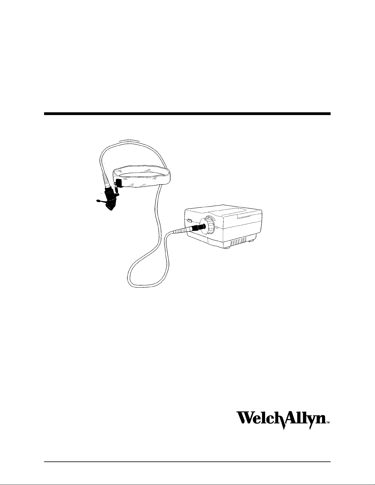
Welch Allyn Single Fiber
Headlights
Operation Manual
Illumination Headlight
System
Service Manual
Copyright 1997
Welch Allyn Inc.
4341 State Street Road
P.O Box 220
Skaneateles Falls, NY 13153-0220
P/N 496144 Rev A.
Models: 49600,49602,49604,49606,
47100,47102,47104,47106
Page 2

Revision (History) Page
Rev. Description of Change ECN # Date Initial
A New Release 5-34455 1/14/97 JJ/MD
SFI Light Source/Luminaire Service Manual Page 2
Page 3

Introduction
To Service Personnel:
The information in this manual is subject to change without notice and should
not be construed as a commitment by Welch Allyn, Inc.
Welch Allyn assumes no responsibility for any errors that may appear in this
manual. If the product and/or its operation varies significantly from any
description herein, please contact the Welch Ally n Product Service Department
at 4341 State Street Road, Skaneateles Falls, New York 13153-0220, 1 800 6699771, (315) 685-4445
This product has been designed to provide a high degree of safety and
reliability. However, we can not guarantee against the deterioration of
components due to aging and normal wear.
All service and repairs must be pe rf o r med b y authorized Welc h Ally n p er sonnel
or agents, u si n g Welc h Allyn replacement p a rts. Failure to d o so will invalidate
the product warranty.
Authorized service centers should refer to repair specification for proper test
and device history record requirements.
Please refer to the product warranty for specific coverage.
Welch Allyn, Inc.
Medical Products
4341 State Street Road
Skaneateles Falls, New York 13153-0220
USA
1 800 669-9771
(315) 685-4445
SFI Light Source/Luminaire Service Manual Page 3
Page 4

Introduction
g
g
g
g
Table of Contents
SECTION 1: General Information
Basic System Description .............6
Specifications ......................7
SECTION 2: Service
Intent of Manual ....................8
Required Tools .....................8
Words of Caution ...................9
Performance Check .................9
Calibration .......................10
SECTION 3: Problem Solving
Troubleshootin
SECTION 4: Disassembly and Repair
SECTION 5: Maintenance
Preventative Maintenance ............22
Cleanin
Checkin
Measurin
Fuse or Lamp Replacement ..........25
SECTION 6: Theory of Operations
Introduction .......................26
Start Up Routine ...................26
Power Supply .....................27
Ballast Board......................27
...................11
.........................23
Ground Impedance ........23
Leakage Current ..........23
SFI Light Source/Luminaire Service Manual Page 4
Page 5

Introduction
Table of Drawings (Appendix A)
N/A ........................................ Parts List/Recommended Inventory
A03569 (Reference Only) .......................Electrical Safety Test Specification
496141 (Reference Only) .................................... SFI Exploded View
496045 (Reference Only) ..................................Interconnect Diagram
Note that the drawings contained within this manual are for reference only. Consult
factory for specific drawing and revision level.
SFI Light Source/Luminaire Service Manual Page 5
Page 6

General Information
Introduction
Basic System Description
Model # 49601 is a medical light source which is used in conjunction with the Welch Allyn SFI
Headlight Luminaire model 49610. The headlight is a lightweight fiber optic system that
provides a bright white light through the use of Arc Lamp technology.
49600....Welch Allyn Light Source
100-240 VAC
50/60 Hz
U.S.A. Plug Type
49602...Welch Allyn Light Source
100-240 VAC
50/60 Hz
European Plug Type
49604...Welch Allyn Light Source
100-240 VAC
50/60 Hz
U.K. Plug Type
49606...Welch Allyn Light Source
100-240 VAC
50/60 Hz
Australian Plug Type
SFI Light Source/Luminaire Service Manual Page 6
Page 7

Section 1 General Information
Specifications
Power Supply
100-240 VAC, 50-60 Hz, Universal input
Power Consumption 40 Watts Max.
Leakage Current: Less than 100 microamps
Light Source Dimensions
WxLxH = 4.5in (11.43cm) x 6.5in (16.5cm) x 2.5in (6.35cm)
Light Source Weight
Under 5 pounds (2.25 Kilograms)
Illumination System
Proprietary Arc Lamp
Color temperature: 5500K
Lamp: 60 Volts, 24 Watts
Lamp Life: 200 hours minimum when employed in a 45 minutes on / 15 minutes off
duty cycle. Average lamp life decreases when shorter duty times are employed.
Dimming System
Manual Shutter: 20% to 100% full output
Fiber Optic Cable Interface
Welch Allyn proprietary connector
Approvals
UL 2601-1 IEC 801-2,3,4,5
CSA C22.2 no. 601.1-M90 EN 55011
IEC 601-1 IEC 601-1-2
Australia AS3200
Light Spot Diameter at 16in (40cm) Distance
Minimum: .75in (20mm)
Maximum: 3.0in (75mm)
Environment
Operating: 60F to 85F
Storage: -13F to 140F
Equipment Classification
Light Source: Type B
Luminaire: Type BF
Fuses
T1.0A L250V (1.0Amp., 250V, time lag (Slow-Blow), Low breaking capacity)
SFI Light Source/Luminaire Service Manual Page 7
Page 8

Service
Intent of Manual
The purpose of this manual is to provide Welch Allyn Inc. authorized servi ce representativ es wi th
systematic guidelines for preventative maintenance, problem identification, and service of the
Welch Allyn Single Fiber Headlight System. We have included the theory of operation schematic
diagrams, simplified drawings, service tips and procedures to assist a trained service
represen tative with board-level repairs. Should you encounter problems that are beyond the
scope of this manual, please contact the Technical Service Depar tment of Welch Allyn's Medical
Products for assistance.
Required Tools for Service
1. 3/8" Nut Driver
2. Screwdriver(s): Phillips #1, Phillips #2
3. Screwdriver: Flat Blade #4
4. Long Nose Pliers
5. Wire Cutters Xcelite 54CG
Required Equipment:
1. Digital Volt/Ohm Meter with Leads (True RMS). Beckman model 310 or equivalent.
2. Soldering Iron
3. Solder Sucker or Desoldering Wick
4. Kepco Model MSK 10-10M Power Supply. Capable of 10 amps at 10VDC.
5. Hy-Pot Tester- Associated Research Inc. Model 35400D or Equivalent.
SFI Light Source/Luminaire Service Manual Page 8
Page 9
Section 2 Service
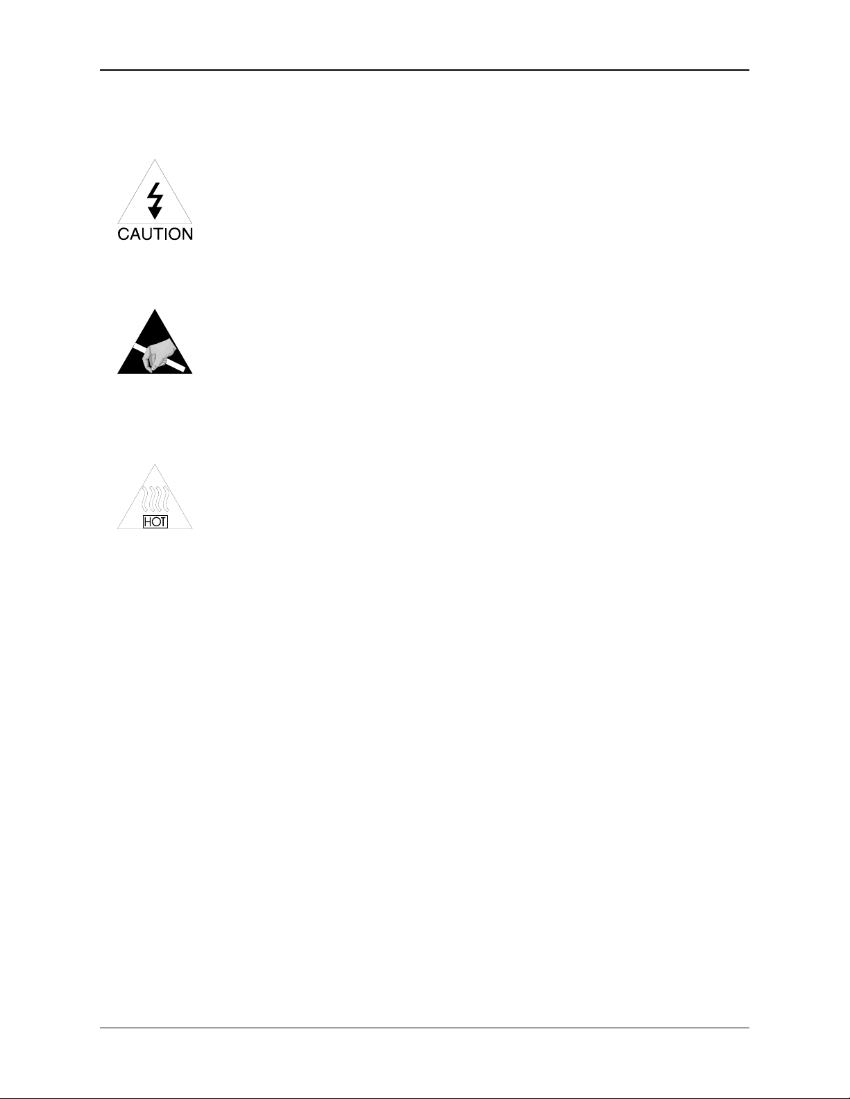
Words of Caution:
High Voltage
Use caution when servicing. When servicing the unit, potentially
dangerous high voltage levels are exposed. Disconnect the
power cord whenever possible to avoid electric shock.
Static Electricity (ESD)
Adhere to standard ESD practices at all times when servicing this
equipment. Many of the electronic devices in this equipment are
static sensitive, and may suffer catastrophic or latent failure if
handled improperly.
Heat
Lamps, power supplies, and heat sinks may emit extreme
amounts of heat during and after operation. Approach and
handle these and other potentially hot components with caution.
Finished Parts
Handle all finished parts with care. The finish can be easily scratched or damaged
from poor or improper handling.
Performance Checks
The following performance checks will help you (1) determine whether or not the system
is operating properly, and (2) isolates a problem, if there is one.
SFI Light Source/Luminaire Service Manual Page 9
Page 10

Section 2 Service
System Set Up
Make sure the system is connected as follows:
1. Be sure that power is being provided by the wall outlet.
2. Be sure that the Lamp is installed properly.
3. Be sure that the cooling fan is turning when the unit is turned on.
4. The light source should produce a bright continuous white light with no
flickering after a warm-up period of 5-15 seconds.
If any of these conditions do not occur, see the troubleshooting section.
Calibrations
Not Applicable
SFI Light Source/Luminaire Service Manual Page 10
Page 11

g
g
g
g
g
g
g
g
Problem Solvin
Troubleshooting
Experience shows that many service calls are due to improper operator technique and
poor connections. Before taking apart the light source, make sure that setup errors are
not caus ing the problem.
signal through the harness wires, connectors, and on the circuit board.
Symptom Possible Cause Procedure
When checking voltages or signals, be sure to verify the
Lamp does not illuminate, but
the fan is runnin
.
Lamp connector is out of place.
Lamp is blown.
Defective ballast
Defective Power supply. No
+15VDC present.
Remove lamp cover and reseat
the connector.
Verify unit functions with a
known
functions with a known
unit.
Verify Volta
of the Ballast board. Refer to
wirin
1KV to 2KV present at the
output during startup.
Check output of power supply
per wirin
Replace supply if no volta
present.
ood lamp or lamp
e input and output
diagram.
Note: There is
diagram.
ood
e is
SFI Light Source/Luminaire Service Manual Page 11
Page 12

Section 3 Problem Solving
g
g
gag
g
g
g
g
g
g
g
g
g
g
g
g
g
Symptom Possible Cause Procedure
Lamp not illuminated, fan does
not function (No power is
apparent).
ht Source overheatin
Li
Power line is damaged or
disconnected.
Power is not turned "ON"
Lamp Door Interlock switch is
disen
AC line fuses F1 and/or F2 are
open.
Open circuit connection.
Power supply circuit defective.
Other circuits loadin
power supply.
Fan Not workin
ed.
down
properly
Connect, repair, or replace as
necessary.
Turn power on.
Verify that the lamp cover is
firmly and properly in place and
that interlock switch is
functionin
continuity to be sure that the
switch is w orkin
Verify and replace as
necessary.
Verify AC input throu
the Switchin
Verify DC output at J2 of
Switchin
If the fuse is blown, disconnect
the plu
Switchin
Replace the blown fuse, and
reapply power. Verify DC
output at J2. If no volta
present or fuse is a
replace Switchin
supply.
Verify correct volta
input and output of the power
supply
496045).
within specification, then
replace motor/secondary wire
harness assembly.
properly. Verify
properly.
h unit to
Power Supply.
Power Supply.
from J2 (Output of the
Power Supply).
e is
ain blown,
Power
es at the
(See wiring diagram
If all voltages are
SFI Light Source/Luminaire Service Manual Page 12
Page 13

Section 3 Problem Solving
g
g
g
g
gg
g
g
g
g
g
g
g
g
g
g
g
g
g
g
g
Symptom Possible Cause Procedure
Light Source over Heatin
Continued..
No li
ht at Luminaire, but light at
ht source.
li
Low li
ht output at Luminaire.
Covered or clo
No +12VDC output from power
supply to operate the fan.
Broken fiber optic cable.
Dirt on fiber optic li
Dirt on li
Solarc li
ht reflector inside the
ht source.
ed air vent.
ht carrier.
Check to see if anythin
coverin
filter is extremely dirty. Replace
filter as described in section 4 if
necessary.
Check volta
Replace power supply if no
volta
Replace fiber optic cable with a
know
Remove the fiber optic cable from
the li
and clean both ends with alcohol
and a cotton swab.
Clean the reflector of any debris
usin
rade methyl alcohol.
Isopropyl alcohol or cotton
swabs.
scratched or pitted the entire lens
platform assembly will need to be
replaced.
the air vents, or if the air
e per wiring diagram.
e is present.
ood cable.
ht source and the Luminaire,
lens paper and an optical
If the reflector becomes
is
Do not use
The shutter assy. in the li
source is misali
workin
.
ned or not
ht
n the shutter gear as shown on
Ali
view "L" below.
SFI Light Source/Luminaire Service Manual Page 13
Page 14

Disassembl
y
p
About This Section:
This section describes how to remove and replace major sub assemblies of the
49601 SFI Light Source.
and Re
air
Note:
reference on the Parts List to determine the correct part number.
Refer to the "Bubble Number" on each drawing and the cross
Part Number Description Bubble # Start Up Qty
496024-501 PLATFORM PKGD 40 1
106124-25 #8 X 1.00 PLASTITE SCREW 41 10
106100-11 PHPS 4-40 X.312 43 10
SFI Light Source/Luminaire Service Manual Page 14
Page 15

Section 4 Disassembly and Repair
Top Housing Assy Disassembly
1. Fan guard:
___
Remove
2. Remove the Top Housing:
___
Remove
housing assembly upwards.
Ballast Board Replacement
1.. Top Housing:
___
Remove
2. Fan Air Baffle:
___
Remove
3. Wire Connectors:
___
Unplug
the top two screws (Phillips) that hold the fan guard in place.
the five screws (Phillips) on the bottom of the unit and lift the top
the top housing.
the two Phillips head screws holding the baffle inplace.
the two connectors located on the ballast board.
4. Lamp Wires:
___
Lift
board, and
5. Reassembly:
___
Reassemble
under the ballast board. The black and white wire from the lamp connector
should be routed through the insulator then resoldered into the proper holes in
the ballast board (refer to wiring diagram).
screws, for they are only screwed into plastic.
the ballast board up, so that it is resting on top of the power supply
Desolder
the black and white wires from the ballast board.
in reverse order. Be sure to reinstall the insulating material
Take care not to over tighten the
SFI Light Source/Luminaire Service Manual Page 15
Page 16

Section 4 Disassembly and Repair
Power Supply Replacement
1. Top Housing:
___
Remove
2. Power Switch:
___
Unplug
supply, by
3. Secondary Output:
___
Unplug
connector with a pair of needle-nose pliers.
4. Grounding Wire:
___
Unplug
5. Wire Tie:
___
Cut
chassis using a small pair of side cutters.
the top housing as instructed in "Top Housing Removal" section.
the connector (J1) with the brown and blue wires from the power
Pulling
the secondary output plug (J2), by
the green and yellow ground wire that attaches to the power supply.
the wire tie that holds the thermal cutout wires to the power supply
straight up on the connector with a pair of needle-nose pliers
Pulling
straight up on the
6. Power Supply Board:
___
Unscrew
board and lift the power supply out of the bottom housing.
7. Reassembly:
___
Reassemble
original position.
screwed into plastic.
the four screws located on the four corners of the powersupply
in reverse order. Be sure to put the insulator back into its
Take care not to over tighten the screws, for they are only
SFI Light Source/Luminaire Service Manual Page 16
Page 17

Section 4 Disassembly and Repair
Fan / Thermal Cutout Replacement
The fan and the thermal cutout come as part of the fan harness assembly; therefore, the
*
entire secondary wire harness assembly must be replaced.
1. Top Housing:
___
Remove
2. Air Baffle:
___
Remove
3. Wire Ties:
___
Cut
4. Fan/Fan Guard:
___
Unscrew
Taking care to remember how the ground wire is connected and routed.
5. Thermal Cut Off Sensor:
___
Remove
sensor switch bracket assembly, and remove the sensor.
the top housing as outlined in top housing removal section.
the two screws that hold the baffle in place, and
the two wire ties that hold the wiring harness to the internal chassis.
the remaining two screws that hold the fan to the bottom housing.
the screw and plastic washer holding the temperature sensor to the
the baffle out.
lift
6. Connectors:
___
Unplug
connector (P2) from the ballast board.
7. Harness:
___
Remove
8. Reassembly:
___
Reassemble
(M11047) needs to be
new thermal switch will be installed.
the 5 pin connector (J2) from the Condor power supply and the 2 pin
the Secondary Wiring Harness assembly.
in reverse order.
applied to
the switch bracket, where the flat side of the
(Note)
A small amount of
thermal compound
SFI Light Source/Luminaire Service Manual Page 17
Page 18

Section 4 Disassembly and Repair
Lamp Cover Safety Interlock Switch:
1. Top Housing:
___
Remove
2. Lamp Cover:
___
Remove
be removed.
3. Safety Switch Assy:
___
Unscrew
bottom housing. Keep the outside insulators.
4. Primary Wires:
___
Disconnect
5. Reassembly:
___
Reassemble
were removed in step #1. Refer to wiring diagram 496045 for additional help.
the top housing as outlined in top housing removal section.
the lamp cover door. The ground wire on the door does not need to
the two Phillips head screws that hold the switch assembly to the
the primary wires from the switch, and remove the switch.
in reverse order. Make sure to reinstall the two insulators that
SFI Light Source/Luminaire Service Manual Page 18
Page 19

Section 4 Disassembly and Repair
Power Switch Replacement
1. Top Housing:
___
Remove
section.
2. Power Switch removal:
___
Unplug
defective switch.
3. Power Switch replacement:
___
Reassemble
quick connect terminals. The switch should
be set into the bottom housing with the "1"
closest to the light attenuator control.
Replacement of the IEC Power Filter
the top housing assembly as described in top housing disassembly
the four quick connect terminals from the switch and
the switch to the four
remove
1. Top Housing:
___
Remove
described on the top housing removal
nstructions.
2. IEC Line Filter:
___
Loosen
screws holding the IEC line filter to
the bottom housing.
3. Primary Wires:
___
Unplug
leading to the interlock switch from the line filter.
4. Ground Wire:
___
Unplug
5. Jumper Wires:
___
Unplug
line filter. Replace these wires if they appear to be damaged.
force is required to push the new wires on to the spade connectors, so use
caution that the spade connector does not get bent.
the Top housing as
the two Phillips head
the brown and blue wires
the Green and yellow ground wire from the IEC line filter.
the brown and blue jumper wires and install them onto the new IEC
A fair amount of
6. Reassembly :
___
Reassemble
assembly drawing 496000 for proper wire connections.
SFI Light Source/Luminaire Service Manual Page 19
in reverse order. Refer to wiring diagram 496045 and
Page 20

Section 4 Disassembly and Repair
Attenuator Control:
1. Reflector platform assembly:
___Remove
section.
2. Gear (Plastic)
___
Push
place by putting a flat blade screwdriver under the closed side of the clip and
prying
3. Knob:
___
Pull
the knob shaft. Remove the bearing and reuse it if a new knob is being installed.
4. Reassembly:
a. ___
Replace
the reflector platform assembly as described in the Reflector Assy.
in on the black plastic gear and remove the "C-clip" that holds it in
upwards.
the knob out of the bottom housing. The bearing will probably stay on
any defective or worn components.
b. ___
housing aligns with the mating part on the bushing.
c. ___
and black gear onto the knob shaft.
d. ___
together, then inserting the c-clip into the grove on the knob shaft.
Reflector Platform Assembly
1. Lamp:
___
2. Lamp Wires:
___
Unscrew
the reflector platform.
3. Top Housing:
___
the bearing into the bottom housing, so that the notch on the bottom
Slide
Slide
Reinstall
Remove
Remove
the knob through the bearing and place the flat washer, spring washer,
the C-clip, by pressing the black gear and the control knob
the lamp socket assembly.
the two screws holding the black and white wire retainers to the bottom of
the top housing as described in the top housing removal section.
4. Thermal Cut Out:
___
bracket.
lift it up and out of the way.
5. IEC Line Filter:
SFI Light Source/Luminaire Service Manual Page 20
the wire ties that hold the thermal cut out wires to the sensor switch
Cut
Unscrew
the Phillips screw that holds the thermal sensor in place, and
Page 21

Section 4 Disassembly and Repair
___
Remove
6. Platform Air Baffle:
___
Unscrew
the baffle straight up.
7. Platform Ground:
___
Unscrew
8. Platform Reflector Assembly:
___
Unscrew
bottom housing.
9. Reassembly:
___
Reassemble
the light attenuator knob fully
Turn
counterclockwise,
knob gear tooth into the 3rd notch
on the flag gear.
the IEC power filter as described in IEC Power filter section.
the two screws holing the baffle to the platform assembly and
the screw holding the ground wire to the platform assembly.
the two remaining screws holding the platform assembly to the
Tilt
in reverse order.
align
lift
the platform assembly and lift it out.
the first
SFI Light Source/Luminaire Service Manual Page 21
Page 22

Maintenance
Preventative Maintenance
The purpose of preventative maintenance is to pro-actively reduce or eliminate future problems.
Keeping the Light Source in good operating condition ensures that it will perform reliably and
safely. Every six to twelve months, you should:
* Check power cable for wear.
* Ensure that, during use, the light source receives adequate ventilation.
* Ensure that the ball detent is still functioning properly.
Visual Inspection
Check for anything out of the ordinary. For instance:
- Does the light source make too much noise?
- Are there any loose parts inside the box?
- Is the power switch working properly?
- Do all components connect/disconnect easily?
SFI Light Source/Luminaire Service Manual Page 22
Page 23

Section 5 Maintenance
CLEANING
Refer to Operating Manual, Welch Allyn Part Number 496027 or 496130.
Check Ground Continuity
1. Disconnect the power cord from the SFI Light Source.
2. Verify the impedance between the ground pin of the IEC detachable ground cord and the
thumb screw meets the requirements as outlined on drawing A03387( see Apnd. A).
Measuring Leakage Current
To check the Chassis Leakage Current:
1. Connect the light source to a leakage tester (refer to figure 5-1), and measure leakage
current on leakage meter. Ensure that leakage is less than 100 microamperes.
2. Open ground line, and ensure leakage current is less than 100 microamperes.
3. Reverse line polarity, and ensure that leakage current is less than 100 microamperes.
4. With reversed polarity, open ground line and ensure leakage is less than 100
microamperes.
CAUTION: The meter must be suitably insulated and
capable of withstanding the power line voltage.
SFI Light Source/Luminaire Service Manual Page 23
Page 24

Section 5 Maintenance
LEAKAGE CURRENT TE ST SET-UP
When the light source is used in conjunction with other accessories, it may be necessary to
measure the leakage current level of the entire set-up. A typical system setup is shown in Figure
5-1. Using a standard leakage tester, this set-up will allow the overall system leakage current to
be measured. If this value exceeds 100 microamps (or whatever the maximu m requirements are
for a particular region), an isolation transformer should be used.
Figure 5-1: Typical Current Leakage Test Set-Up
SFI Light Source/Luminaire Service Manual Page 24
Page 25

Section 5 Maintenance
FUSE REPLACEMENT
1. Turn the power switch OFF and disconnect the power cord from the light source.
2. Open fuse drawer located as part of the power cord receptacle.
3. Remove fuse by pulling it out firmly.
4. Check fuse condition. Replace if blown. Replacement
fuse: 250V, 1.0 Amps. 5 x 20mm , Slow-Blow.
fuse only! An unqualified fuse may fail prematurely.
Use WA
5. This system has two fuses. Be certain to check the
condition of both fuses.
LAMP REPLACEMENT
Refer to users manual 496027 or 496130 for full detail.
1. Turn the power switch OFF and disconnect the power cord from the light source.
2. Wait a minimum of 5 minutes to allow the lamp to cool.
3. Remove the lamp cover on the bottom of the Light Source by unscrew ing the thumb screw
on the bottom of the light source.
NOTE:
Removing the cover will automatically cut off p ower to the Light Source.
4. Loosen the thumb screw that holds the metal bracket in place over the Lamp Assy.
5. With the metal bracket up out of the way, remove the lamp assembly by pulling straight up.
6. Acquire new replacement lamp assembly.
7. Reseat the new lamp assembly. It will make a "click" sound when fully seated.
8. Slide the black connector on to lamp, and secure the metal bracket that holds the lamp
assembly in place.
Note:
Route wires to the sides of the metal bracket, not under it. See the picture on the
inside of the lamp cover.
9. Secure the lamp cover, reconnect the system, and verify lamp operation.
SFI Light Source/Luminaire Service Manual Page 25
Page 26

Introduction
Theory of Operation
SFI Light Source
Model # 49601 is a
:
medical light source
which is used in conjunction with the Welch Allyn
single fiber Luminaire. The light source is comprised of a power supply, a ballast, and an ArcLamp. The light generated by the Arc-Lamp is focused into a sm all single point by using two
reflectors. The re fl e c t ors a nd t h e lamp are optically aligned at the factory; therefore, there is
no repair to these subassemblies.
SFI Luminaire:
Model # 49610 Cogent Luminaire, designed and assembled by Cogent Light Technologies, is
designed to work with the SFI light source and single fiber optic cable. The Luminaire utilizes a
series of adjustable lenses to focus the light into a spot of diameter of 25mm-77mm at a distance
of 16in.. The joystick assembly is the only replaceable part on the Luminaire.
Single Fiber Cable:
The Welc h Allyn Single Fiber Optic Cable is a lightweight quartz glass fiber within a Teflon and
silicone jacket. The fiber-optic cable has approximately 11 feet of useable length from the light
source to the Luminaire. There are no repairable parts on this component of the SFI system.
Start up Routine (Lamp Ignition)
Upon turning the power switch to the "ON" position, the lamp ballast will ignite the lamp s for an
approximate warm-up phase of 15 seconds. Once this warm-up phase is complete, the the
lamps will be warmed up, and the system will be ready for use.
Note: The fiber bundle must be in place to stabilize light output. Do not toggle the power
switch ON and OFF. Doing so will dramatically shorten lamp life.
SFI Light Source/Luminaire Service Manual Page 26
Page 27

Section 6 Theory of Operation
Power Supply
UNIVERSAL INPUT, SWITCHING AC TO DC MEDICAL GRADE POWE R SUPPLY
The power supply accepts an input v ol tag e of 100-240 VAC, 50- 60 H z, single phase. The primary
circuit provides adequate control of leakage current, which is limited to 35 microamperes
maximum. The pri mar y side of the power s upply recti fi es t h e AC voltage and converts it to a high
voltage DC level. This DC voltage is connected to the isolation transformer through a switching
device, typically a mosfet. The mosfet is triggered by a high frequency clock circuit, typically at a
30-50 KHz rate. The secondary side of this transformer provides isolation between primary and
secondary circuits. The secondary voltage is rectified and filtered to provide a +15 VDC output
voltage at 5.3 amps. The output voltage is regulated to 2%, with peak-to-peak noise of 150mV.
The output is fully protected against short circuit and output overload. Short circuit protection is a
cycling type power limit with automatic recovery after fault.
Ballast Board
The ballast board is a power supply used to operate the 24 watt Welch Allyn miniature arc lamp.
The nature of arc lamps require a ballast which limits the current, and therefore the power, in the
lamp. There are three states of the operation of the ballast: ignition, warm-up, and steady state.
In ignition the ballast provides the lamp with a train of ignition pulses between 6 and 7 kV. Once
the lam p is ignited the ballast conducts current at a very low impedance, which constitutes the
warm-up phase. Once it warms up, the impedance changes to a higher steady state value. The
ballast board also controls the Bulb Replacement indicator located directly next to the attenuator
contro l. Th is lamp will light when the output voltage to the lamp exceeds 61.5VDC, which is an
indication that the Arc Lamp is going to or has failed.
SFI Light Source/Luminaire Service Manual Page 27
Page 28

Appendix A
Part Number Description Bubble # Start up order
Qty
761076-0 POWER CORD,
DETACH.(DOM/JAPAN)
761076-2 POWER CORD,
DETACH. (EUROPE)
761076-4 POWER CORD,
DETACH. (U.K.)
761076-6 POWER CORD,
DETACH. (AUSTRALIA)
496017-1 LABEL NAMEPLATE - DOMESTIC
(USA)
496017-2 LABEL NAMEPLATE -
INTERNATIONAL
496028-501 CARTON ASSY, COG LT BOX NA 5
496002-1 BOTTOM, LIGHT BOX (COATED) 1 1
496071 AIR FILTER 2 5
496080 INTERLOCK SWITCH 3 1
496081-501 HARNESS ASSY (SWITCH) 5 5
495074 INSULATING PLATE 6 10
NA 2
NA 2
NA 2
NA 2
NA 5
NA 5
451534 SCREW PHP #4-40 X1.0 7 10
106124-1 PLASTITE PAN HEAD SCREW 9 10
455508 LABEL, PROTECTIVE EARTH
GROUND
106106-7 GROUND LOCK WASHER 11 10
106105-4 SPLIT RING WASHER 12 10
106109-9 NUT 13 10
495075 BALLAST SIDE CONN ASSY C12A003 16 5
496025 INSULATOR, BALLAST 17 5
495068 BALLAST 24W UNREGULATED 19 5
106124-34 #4 X.375 PLASTITE PHPS 21 10
496131-501 HARNESS ASSY (LED) 22 5
106132-3 4-40 X 1 23 10
10 5
SFI Light Source/Luminaire Service Manual Page 28
Page 29

Appendix A
Part Number Description Bubble # Start up order
Qty
106106-2 #4 INTRNL TOOTH LOCKWASHER 24 10
495067 FAN GUARD 25 0
496093 FAN MOUNTING RING 26 0
496062-504 HARNESS ASSY, FAN 27 5
496124 FAN NUT PLATE 28 0
106105-3 #4 LOCKWASHER,HEL 29 10
790043 4-40 X .250 HEX NUT 30 10
106132-5 4-40 X .750 PH TR MS SS 31 10
880031 POWER SUPPLY 40 WATT 32 5
496026 INSULATOR, POWER SUPPLY 33 10
106144-4 BEARING, NYLINER 34 2
496005 KNOB, COGENT LT BOX 35 2
496075 WASHER, ATTENUATOR KNOB 36 2
496068 BOWED WASHER 37 2
496023 GEAR,KNOB COGENT LT BOX 38 2
106101-18 RETAINING RING 39 2
496024-501 PLATFORM PKGD 40 1
106124-25 #8 X 1.00 PLASTITE SCREW 41 10
106100-11 PHPS 4-40 X.312 43 10
496076-501 SHAFT ASSY, GEAR/ATTENUATOR 48 1
106101-17 RETAINING RING 49 6
496077 ATTENUATOR FLAG ASSY 50 1
106103-38 WASHER, PIVOT 51 10
SFI Light Source/Luminaire Service Manual Page 29
Page 30

Appendix A
g
Part Number Description Bubble # Start up order
Qty
488308-4 Cable Clamp 53 20
M11047 Thermal Compound #120-5
713104 6-32 X .186 Phph
761077-1 Tie Wrap
106103-37 Pivot Washer
106100-46 10-32 X .25 Screw
106124-9 Screw
496123 IEC Power Filter
106100-42 4-40 X .25 Screw
236706-3117 Fuse
236733 Fuse Drawer
106120-4 6-32 X .750 Screw
496033 Lamp Access Door Knob
09600-501 Fixtured Lamp Packa
495083 Rubber Feet
M30373 Loctite 425
47143 Fiber Optic Cable (304.8cm)
49571 Joystick Assembly (Post on Luminaire.)
e
54
56
57
55
58
60
63
64
65
66
70
71
76
77
78
NA
NA
N/A
10
50
5
10
10
0
10
20
1
10
0
3
0
0
20
10
SFI Light Source/Luminaire Service Manual Page 30
Page 31

Appendix A
Reference Drawing #A03569
SFI Light Source/Luminaire Service Manual Page 31
Page 32

Page 33

 Loading...