

Welbilt Delfield CV5E, Delfield CV10E, Delfield T40, Delfield CV15E-2, Delfield CV15E Original Instructions Manual
Fresh Solutions, Fit for You
Blast Chillers
CV5E, CV10E, CV15E, CV15E-2 and T40
Original Instructions
Installation, Operation and Maintenance Manual
This manual is updated as new information and models are released. Visit our website for the latest manual.
Part Number: 9294045 07/19

1 WARNINGS AND IMPORTANT ADVICE
2 TECHNICAL DATA
2.1 - Plate data
2.1 - Refridgerant
2.3 - Measurements
2.4 - Maximum loads
2.4.1 - Max load for internal structure capacity
2.4.2 - Max tray capaity
3 INSTALLATION
3.1 - Transportaion and handling
3.2 - Unpacking and disposal
3.3 - Positioning
3.4 - Ambient temperature and air exchange
3.5 - Hydraulic connection for water cooled units
3.6 - Electrical connection
3.7 - Remote group refrigerator connection
3.8 - Condensate drainage connection
3.9 - Notes for the installer
3.10 - Commissioning
3.11 - Safety and control systems
3.12 - Stop modes
3.13 - Signaling/reports of malfunction
3.14 - Appliance disposal
4 COMMAND INTERFACE SYMBOLS
5 MACHINE ON/OFF
5.1 - Compressor preheating management
6 DATE AND TIME SETTINGS
7 BLAST CHILLING CYCLES
7.1 - General chilling principles
7.1.1 - Chilling time
7.1.2 - Temperature chilling
7.1.3 - Chilling and storage status symbols
7.2 - Chilling phases
7.3 - Selecting and starting the pos. chill cycle
7.4 - Selecting and starting the neg. chill cycle
7.5 - Storage phases
8 DEFROST MODE
9 DRYING WITH MACHINE AT STANDSTILL
10 DOOR OPENING
11 OZONATOR
12 ICECREAM CYCLE
13 THAWING CYCLE
14 CHILLING PROGRAM STORAGE
15 CHILLING PROGRAM EXECUTION
16 ALARMS
10
10
10
10
10
11
12
12
12
12
12
12
12
12
13
13
13
14
14
14
14
15
15
15
16
16
16
2
5
5
5
6
7
7
7
8
8
8
8
9
9
9
9
9
9
16.1 - Evaporator probe alarm
16.2 - Product probe alarm
16.3 - Cell probe alarm
16.4 - Door micro-switch alarm
16.5 - Alarm - Diff. Thermal Breaker - Oil Pressure
16.6 - Auto reset minimum pressure swtich alarm
16.7 - Auto reset Kriwan Alarm
16.8 - Input alarm HT 1 - Fusable
16.9 - Overtemperature
16.10 - Black-Out Alarm
16.11 - Compressor preventative maint. alarm
16.12 - Temperature not reached in time alarm
16.13 - Power keypad-card connection alarm
16.14 - Maximum pressure switch alarm
17 HACCP ALARM MEMORIES RESET
18 HACCP DATA READING
19 HACCP DATA EXPORT WITH USB
19.1 - Extracted data format
19.2 - Data downloading with USB
20 ORDINARY MAINTENANCE
20.1 - Operations by the user that do not require
assistance of a qualified technician
20.1.1 - Cell cleaning
20.1.2 - Outer case cleaning
20.1.3 - Defrost water drainage
20.2 - Operation only for authorised installer
20.2.1 - Condenser cleaning
20.2.2 - Condenser filter cleaning
20.2.3 - Evaporator cleaning
20.2.4 - Ozonator maintenance
21 TIPS FOR SMOOTH OPERATION
21.1 - Operating instructions
21.2 - Pre-cooling
21.3 - Maximum load capacity for chilling/freezing
cycles
21.4 - How to load the machine
T40 information
1 UNIT INFORMATION
1.1 - Freezer Remote condensing unit details
1.2 - Remote water cooled condensing unit
1.3 - T5/T14D Refrigeration system schematic
1.4 - Wiring diagram
2 T40 INSTALLATION AND ASSEMBLY
2.1 - Supplied Equipment list
2.2 - Install and assembly instructions
3 - Controller buttons
4 -Controller functions
5 - Programming instructions
5.1 - Starting up the appliance
16
16
16
17
17
17
17
17
17
18
18
18
18
18
18
18
19
19
19
20
20
20
20
20
20
20
20
20
20
20
20
20
21
21
22
23
23
24
25
26
27
27
28
31
32
33
33
2 Part Number: 9294045 07/19

Table of Contents
5.2 - Soft blast chilling by temperature
5.3 - Soft timed blast chilling
5.4 - Hard blast chilling by temperature
5.5 - Hard timed blast chilling
5.6 - Blast freezing by temperature
5.7 - Timed blast feezing
6 APPLIANCE FUNCTIONS
6.1 - Date and time settings
6.2 - Ice cream surface hardening
6.3 - Muting the beeper and alarm
6.4 - Program storage
6.5 - Displaying the three latest HACCP alarms
6.6 - printing out stored data
6.7 - Forced ventilation function
6.8 - Manual defrosting
6.9 - Automatic defrost cycles
6.10 - Printer operation
7. ALARM MANAGEMENT
7.1 - Storage of data/errors
7.2 - Software controls
33
34
34
35
35
36
37
37
37
37
37
37
37
38
38
38
38
39
39
39
Part Number: 9294045 07/19 3
Safety Notices
Warning
n
Read this manual thoroughly before operating, installing
or performing maintenance on the equipment. Failure
to follow instructions in this manual can cause property
damage, injury or death.
DANGER
Do not install or operate equipment that has been
misused, abused, neglected, damaged, or altered/
modified from that of original manufactured
specifications.
DANGER
Keep power cord AWAY from HEATED surfaces. DO NOT
immerse power cord or plug in water. DO NOT let power
cord hang over edge of table or counter.
DANGER
All utility connections and fixtures must be maintained
in accordance with Local and national codes.
Warning
n
Authorized Service Representatives are obligated to
follow industry standard safety procedures, including,
but not limited to, local/national regulations for
disconnection / lock out / tag out procedures for all
utilities including electric, gas, water and steam.
Warning
n
Do not store or use gasoline or other flammable vapors
or liquids within or in the vicinity of this or any other
appliance. Never use flammable oil soaked cloths or
combustible cleaning solutions, for cleaning.
Warning
n
Do not use electrical appliances inside the food storage
compartments of the appliance, unless they are of the
type recommended by the manufacturer.
Warning
n
Use caution when handling metal surface edges of all
equipment.
Warning
n
This appliance is not intended for use by persons
(including children) with reduced physical, sensory
or mental capabilities, or lack of experience and
knowledge, unless they have been given supervision
concerning use of the appliance by a person responsible
for their safety. Do not allow children to play with this
appliance.
Caution
,
Use caution handling, moving and use of the R290
refrigerators to avoid either damaging the refrigerant
tubing or increasing the risk of a leak. Components
shall be replaced with like components. Servicing shall
be done by a factory authorized service personnel to
minimize the risk of possible ignition due to incorrect
parts or improper service.
Notice
Proper installation, care and maintenance are
essential for maximum performance and trouble-free
operation of your equipment. Visit our website www.
wbtkitchencare.com for manual updates, translations,
or contact information for service agents in your area.
Warning
n
This product contains chemicals known to the State
of California to cause cancer and/or birth defects or
other reproductive harm. Operation, installation, and
servicing of this product could expose you to airborne
particles of glasswool or ceramic fibers, crystalline
silica, and/or carbon monoxide. Inhalation of airborne
particles of glasswool or ceramic fibers is known to the
State of California to cause cancer. Inhalation of carbon
monoxide is known to the State of California to cause
birth defects or other reproductive harm.
Section 2 Technical Information
2 TECHNICAL DATA
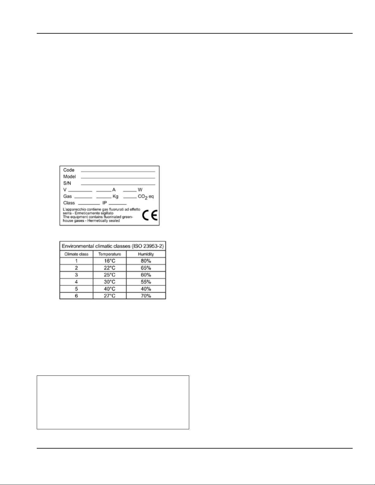
2.1 - Plate data
The plate bearing the equipment specifications should
be applied on the outside rear part of the machine and/
or on the electrical panels. Any preparation of machines
only for relocation of the condensing units must follow
the regulations enforced in the country of installation
regarding fire safety (refer to the command of the local
fire department for the relevent indications). It should
also be considered that the possible intervention of safety
valves or fusible plugs, located in the refrigerant circuit,
entail the immediate discharge of all the refrigerant into
the environment.
The appliance’s climate class is stated on the serial plate
2.2 - Refrigerant
The appliance contains flourinated greenhouose gases
covered by the Kyoto Protocol in the quantities indecated
on the serial plate. The type of refrigerant gas present in
the refrigerant circuit of the appliance is shown on the
serial plate. The GWP (global warming protential) of the
HFC R134a gas is 1430 and the HFCR404A gas is at 3922.
The CO2 equivalent data is shown on the serial plate.
,
According to regulation (EC) 1272/2008,
,
R134a and R404A gases are non-flammable
and non-toxic. in high concentrations they
cause burns and frostbite. in the system the
gas is pressurised; it may explode if heated.
Part Number: 9294045 07/19 5
Technical Information Section 2
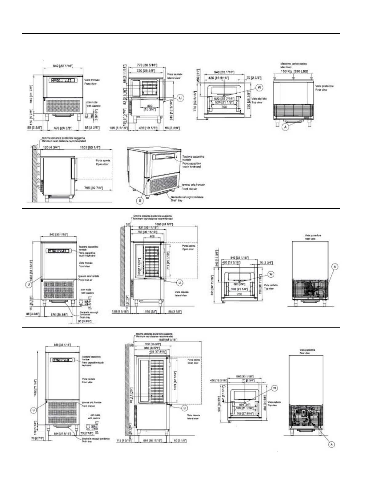
2.3 - Measurements
CV5E - 5 trays
CV10E - 10 trays
CV15E - 15 trays
6 Part Number: 9294045 07/19
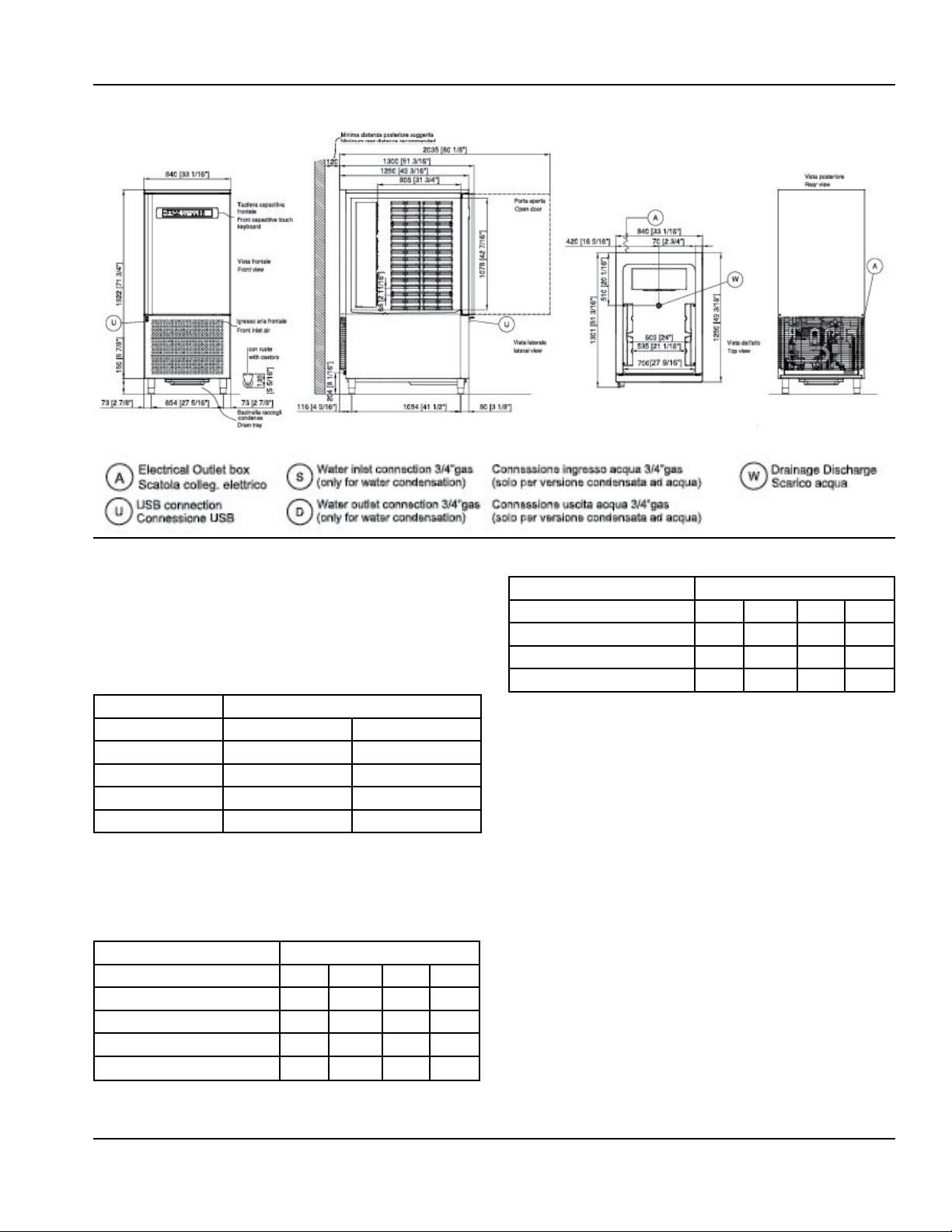
Section 2 Technical Information
CV15E-2 - 30 trays
2.4 - Maximum load
,
Operators are strongly suggested to follow
enclosed instructions
2.4.1 - Maximum load for internal structure capacity
Maimum Capacity
Model Internal structure load per shelf
5T 1000oz (30kg) 700oz (20kg)
10T 1600oz (45kg) 700oz (20kg)
15T 2800oz (80kg) 700oz (20kg)
30T 3000oz (85kg) 700oz (20kg)
2.4.2 - Maximum trays capacity
(trays not supplied with the appliance)
Standard internal support structure
Model
Size Trays 5t 10T 15T 30T
15¾” x 23⁄” (600x400mm) 5 10 15 30
12¾” x 20¾” (530x325mm) 5 10 15 30
23⁄” x31½” (600x800mm) n/a n/a n/a 15
12¾” x 41½” (530x650mm) n/a n/a n/a 15
Optional internal support structure
Model
Size Trays 5t 10T 15T 30T
18” x 26” (655x453mm) n/a n/a n/a 15
12¾” x 20¾” (530x325mm) n/a n/a n/a 28
12¾” x41½” (530x650mm) n/a n/a n/a 14
Part Number: 9294045 07/19 7
Technical Information Section 2
3 INSTALLATION
,
All stages of installation must be carried out in
,
compliance with the national standards in force
according to the manufacturer’s instructions and
by professionally qualified personnel.
Installation of the appliance and of the refrigerating
unit must only be carried out by technicians of the
manufacturer or by skilled personnel.
If the machine was supplied with a remote condesing
unit, it is the installer’s responsibilty to check all the
connections in accordance with the instructions provided
for the installation of the systems and machinery.
The installer is advised to use the appropriate personal
protective equipment necessary for processing and in
compliance with the regulations in force.
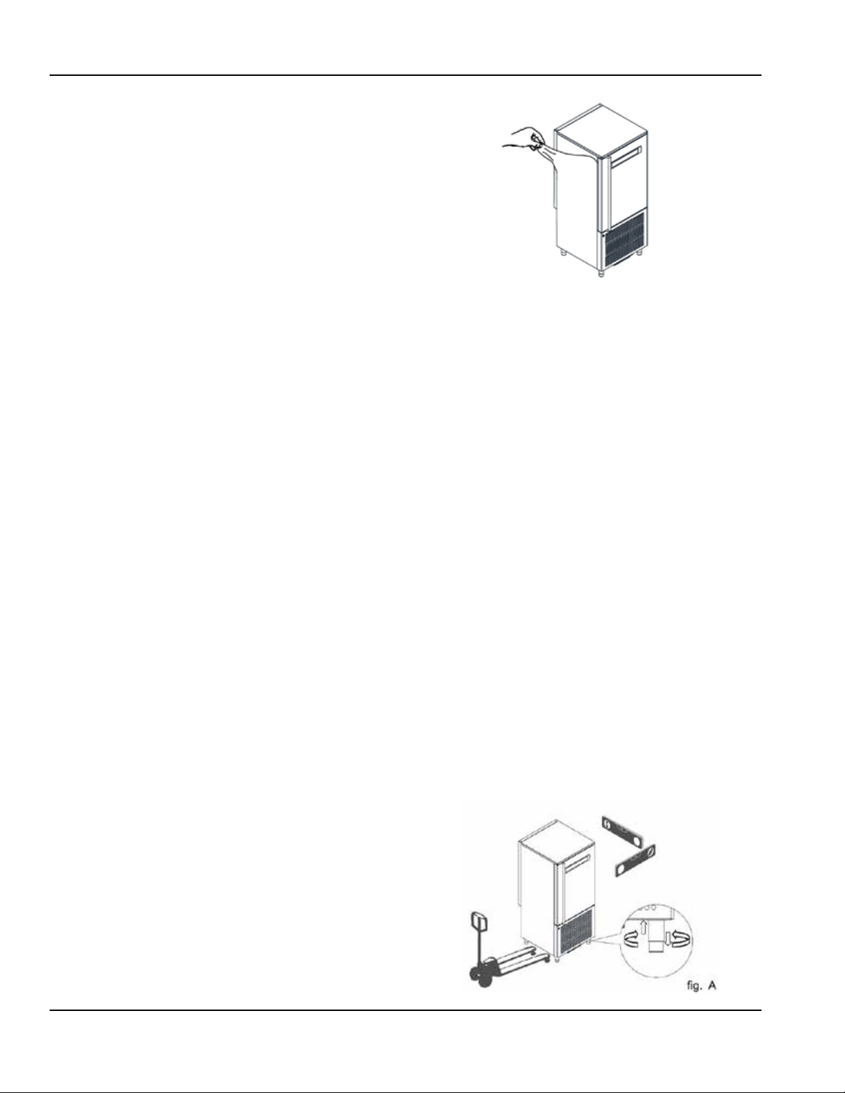
3.1 - Transportation and handling
The net and gross weight of this appliance can be found
on the external packaging.
Loading and unloading of the appliance and/or of the subsystems from the means of transport can be performed
using a forklift truck or fork pallet truck, the length of
which is more than half that of the unit or using cranes
where the apppliance/sub-system is fitted with eyebolts.
The lifting equipment must be chosen according to the
size of the packaged machine/components and with
sufficient capacity. For handling of the appliance/subsystems, every precaution must be taken not to damage
them, respecting the indications on the packaging.
3.2 - Unpackaging and disposal
Remove all cardboard or the wooden crate from the base
on which the machine is placed. Then lift the machine/
sub-assemblies with a suitable means (forklift truck);
remove the wooden base and position the machine/subassemblies in the place provided.
After removing the packaging, verify the integrity of the
machine/sub-assemblies in case of uncertainty do not use
it and contact the distributor.
Remove the protective PVC film on the stainless steel
panels from all sides both internally and externally.
NOTE: All the various components of the packaging must
be disposed of according to the regulations in force in the
country where the appliance is being used. In any case
nothing must be disposed of into the environment.
3.3 - Positioning
The appliance:
• must be installed in places where it can be checked by
qualified personnel
• it must not be installed outdoors.
• it must not be installed in dusty environments.
• it must not be placed in locations with the presence of
water jets.
• it must not be washed with water jets.
• it must be installed and tested in full compliance with
safety laws, traditional systems and with the regulations
in force.
• it must be positioned at a minimum distance of 120mm
from the rear wall.
The installer must verify any requirements for fire safety
(refer to the command of the local fire department for the
relevant indications.)
Level the appliance through adjustment of the feet. For
the setting up of heavier machines, use dedicated hoists
(fig. A - chap. 3.1).
If the appliances are not levelled their functioning and the
flow of condensates could be impaired.
8 Part Number: 9294045 07/19
Section 2 Technical Information
,
Avoid:
• direct exposure to sunlight;
• closed sites with high tempuratures and poor air
circulation;
• indoor environments at high temperatures and poor air
circulation, and avoid installing the machine near any
heat sources
3.4 - Ambient temperature and air exchange
For air cooled liquid chillers, the ambient operating
temperature must not exceed 90°F (32°C). Above this
temperature the declared performance is not guaranteed.
The machine can operate safely up to a temperature that is
referref to by the climate class indicated on the serial plate.
Remote condensing units must be instaled in special rooms
or, if outdoors, in a place protected from direct sunlight,
from adverse weather conditions and from heavy wind
(above 5m/sec). Where circumstances so require, it is the
responsibility of the installer to evaluate the use of a cover
or canopy (costs to be borne by the purchaser). In any case
sufficient air circulation must be guaranteed.
3.5 - Hydraulic connection for water cooled condensing
units
It is advisable to install a valve between the mains and
the appliance’s inlet hose in order to be able to stop the
passage of water if necessary.
For appliances with water cooled units the water supply
temperature must be between 50°F (10°C) and 86°F (30°C)
and the operating pressure must be between 0.1 MPa (1 bar
- 14psi) and 0.5 MPa (5 bar - 72 psi).
regulations in the country of installation.
The electric connecting cables must be dimensioned
in accordance with the rules in force in the country of
installation. In cases wwhere the power cord of the
appliance is damaged, it must be replaced with another
with characteristics that comply with the rules in force in
the country of installation and performed by a qualified
personnel in order to prevent any risk to persons.
The earthing conductor must be correctly connected to
an efficient earthing system.
The manufacturer declines any responsibility and any
warranty obligation in the event of damage to the
equipment, to persons and property caused by incorrect
installation and/or failure to respect the applicable laws.
3.7 - Remote group refrigerator connection
The diameters of the supply lines of the equipment
are sized for distances of up to 10 meters. Contact the
manufacturer for longer distances.
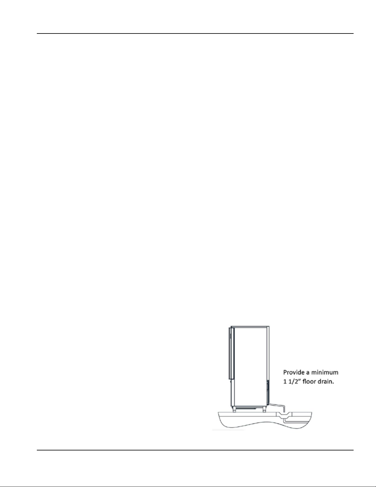
3.8 - Condensate drainage connection (if applicable)
It is necessary to provide a drainage pipe for the
condensation and washing water of a minimum diameter
of 1”. It is advisable to dispose of the condensate through an
open drain at ground level and fitter with a siphon with a
minimum diameter of 1/2”.
3.9 - Notes for the installer
• Verify the correct installation and system testing before
starting up the machine (test report).
• Check for any gas leaks from the welds or joints made
during the installaition phase.
3.6 - Electrical connection
No responsibility is accepted for damage to
,
persons, animals or property cause by failure
to earth the appliance and the creating of an
electrical installation that does not comply with
current standards.
The mains connection must be made according to existing
national rules and by experienced, qualified personnel.
Before connecting the appliance to the mains make
sure that the mains voltage corresponds to the voltage
indicated on the data plate.
Verify that the electrical installation is adequate to the
maximum power of the appliance, as indicated on the
plate. Upstream of each device it is mandatory to install
a differential thermal breaker according to current
Part Number: 9294045 07/19 9

Technical Information Section 2
• Check the efficient insulation of the connecting pipes
between the condenser and the remote condensing
unit.
• Check the electrical connection
• Check the electrical input
• Verify the standard pressures of the refrigerating system
• Check the water connections with adjustment of the
pressure valve during operation and good circulation of
the condensation water (water cooled groups).
3.10 - Commissioning
Commissioning must be carried out by
,
authorised and qualified personnel.
Perform at least one complete cycle of rapid storage
freezing (to reach the SET temperature), and a manual
defrost cycle. If the equipment or the remote condensing
units were delivered in an upright position (e.g. on their
back) or were overturned during installation, do not turn
on immediately but wait at least 4 hours before use.
Inform the customer of the exact use of the equipment
with specific reference to the use and to customer
requirements.
3.13 - Signalling/reports of malfunctioning
In cases of malfuntion of the machine and for report
signalling concerning the blast chillers supplied.
Assembled
You are requested to communicate to the retailer/service
center the machine model, code and the serial number
shown on the registration plate located on the rear of the
machine and inside the door.
Dismantled (with condesnsing units/remote
condensors)
You are requested to communicate to the retailer/service
center the machine model and the code shown on the
registration plate located above the control panel.
3.14 - Appliance disposal
After the useful life of the appliance has been realized be
sure to demolish and dispose of the machine in compliance
with the regulations applied in the country of installation,
particularly in regards to refrigerant gas and compressor
lubricant oil.
3.11 - Safety and control systems
• Door microswitch: this locks operation of the fans in the
cell when the door is opened.
• General protection fuses: they protect the entire power
circuit against short circuits and possible overloads.
• Compressor thermal relay: this intervenes in case of
overloads or malfunction.
• Safety pressure switch: this operates in the case of
excess pressure in the refrigerant circuit.
• Fusible plug: this intervenes in the case of overpressure
and failure of the afore-mentioned safety pressure
switch.
• Chamber temperature control: this is operated by the
electronic card via the probe positioned inside the cell.
• Defrost termination temperature control: this is
managed by the electronic card via the probe located
on the evaporator.
3.12 - Stop modes
In an emergency, to stop the machine remove power from
the main panel using the earthing switch or by removing
the plug from the socket making sure hands are not wet or
damp.
10 Part Number: 9294045 07/19
Section 2 Technical Information
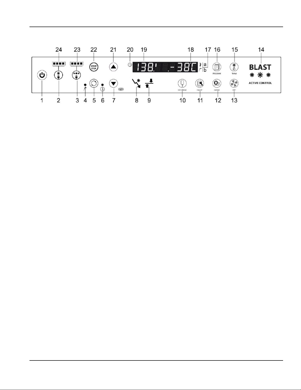
4 COMMAND INTERFACE SYMBOLS
1 - Stand-by button - Standby button, if pressed for more
than 3 seconds it takes the card into standby or switches
it on again.
2 - Positive chilling button - Used to select the mode of
positive chilling.
3 - Negative chilling button - Used to select the mode of
negative chilling.
4 - Chill. LED Temperature - LED on means that the chilling
is via tempurature mode (insert probe)
5 - Chilling mode button - A button that selects the mode
of chilling with Time or Temperature (insert prode use);
the selected mode is represented by ignition of one of the
two LEDs located on the right and left of the button and
the are marked with the temperature or time symbol.
6 - Chill. LED Time - LED on means that the chilling is via
Time mode
7 - Decrease button - Parameter or setting value decrease
buttons (the “-” button allows silencing of the beeper if
active.)
8 - Chilling phase LED - Symbol representing the chilling
phase (it flashes when at that phase.)
9 - Storage phase LED - Symbol representing the chilling
phase (it flashes when at that phase.)
10 - Ice-cream button - The ice-cream button which starts
the ice-cream cycle. (see section 12).
11- HACCP button - The HACCP button which starts the
data reversal cycle onto USB.
12 - Ozone button - Button that starts the ozone sanitising
cycle (if any).
13 - Defrost button - Button that when pressed once starts
drying with door oper (see section 9), while if pressed for
at least 3 seconds it starts the hot gas defrost cycle.
14 - Status LED - RGB on mark lettering. The lettering
assumes the following colors depending on the following
relative connected states:
BLUE - Phase of chilling, deep-freezing or storage
ORANGE - Thawing
GREEN/BLUE - Machine on stand by
WHITE - Machine at standstill
RED FLASHING - Serious alarm
FLASHING YELLOW - Non-serious alarm (door opening -
maintenance)
15 - Thawing button - Button that when pressed starts the
defrost cycle
16 - Program button - Programs recall or storage button
17 - Temperature symbol - The symbol lights up when a
cycle is active and the cell temperature (time chilling) or
product temperature (temperature chilling) is detected.
In the second case the product probe is shown with the
highest value. With the cycle in progress press the button
(12) to display in sequence the values of the insert probe
1 and 2 and the evaporator sensor probe in flashing mode
and the display (19) will show the letters in sequence SP1+
“probe value”, SP2+”probe value” and SE+”value”.
18 - Display temperature - Second part of the alphanumeric
desplay (last 4 digits) for representation of the T° cell or T°
product and evaporater value.
19 - Display time - First part of the alphanumeric display
(first 4 digits) for representation of the time value
remaining of chilling.
20 - Time symbol - The symbol lights up when the cycle
is running; the time remaining will be displayed. If the
button (5) is pressed the elapsed time will flash for 5
seconds (both for Time and Temperature chilling).
21 - Increase button - Parameter or setting value increase
buttons.
22 - Cycles start/stop button - start/stop the chilling cycle
set; with a cycle started, the button remains lit.
23 - Negative chilling LED - The number of LEDs lit indicates
the intensity of the negative chilling.
24 - Positive chilling LED - The number of LEDs lit indicates
the intensity of the positive chilling.
Part Number: 9294045 07/19 11

Technical Information Section 2
5 MACHINE ON/OFF
When the equipment is powered, it will appear in
STANDBY conditions (scrolling text on the display). To start
the machine press the button (1) for at least 3”. Similar to
machine without cycles in progress, to switch it off simply
press the button (1) for at least 3”.
Where a cycle was in progress, and the situation is returning
from a blackout the appliance, once reconnected, will
resume from the interrupted cycle.
5.1 - Compressor preheating management
Upon ignition of the equipment a compressor preheating
time of 120 minutes must be respected where the blast
chiller is not available.
The scrolling text will appear “Compressor HeatingRiscaldamento Compressore” and then the fixed lettering
“XXX min” to represent the time remaining. These two
messages will alternate until the end of heating. This phase
can be bypassed by pressing the “HACCP” (11) button for
approximately 5 seconds.
6 DATE AND TIME SETTING
Upon initial ignition, it is advisable to check the date and
time set; their accuracy is beneficial in relation to HACCP
management.
To access the clock setting, press for more than 5 seconds
the Temperature/Time button (5) with the machine in
Stop mode. The laels shown below will appear on the left
display; the right display will show the 2-digit numeric
value to be set:
Hour(Ora) / Minute(Minuti) / Day(Giorno) / Month(Mese) /
Year(Anno)
The Temperature/Time button (5) can be used to scroll
through the labels, while with the +/- buttons (21/7) it is
possible to change the values.
After the year value the change will be automatically
saved.
7 BLAST CHILLING CYCLES
7.1 - General operating principles
Pre-cooling of the machine should always be performed
upon initial running of a blast chilling or deep freezing
operation. This optimises the subsequent work cycle,
reducing the time.
Blast chillers are refrigeration systems that work with a twophase cycle:
• Chilling phase (limited duration)
• Storage phase (unlimited period)
The chilling phase starts upon pressing of the “Start/Stop”
button (22) and continues until the end of the chilling
phase that is used to achieve the time set (Time chilling) or
for reaching of the product temperature set (Temperature
chilling); changing to the unlimited duration storage cycle
takes place automatically (except for the the HARD+HARD
negative chilling cycle). It is possible to stop the chilling
or storage at any time by pressing the “Start/Stop” button
(22).
Chilling time
During this type of chilling, the display (18) shows the cell
probe temperature while the other display (19) shows the
time remaining at the end of the chilling phase. The Time
chilling LED (6) is lit as is the time symbol (20).
Temperature chilling
If Temperature chilling is selected, at the start of a cycle a
check is performed of the correct insertion of the product
probe (if enabled). If the test provides a negative result
an alert appears on the display “SONDA NON INSERITA PROBE NOT INSERT” and the beeper sounds for 60 seconds
(parameter c9); that symbol disappears when the beeper
is silenced by pressing the button (7). If instead the button
is pressed again (5) switching to Temperature cycle, the
cycle continues based on the data read by the product
probe. If nothing is pressed, the temperature cycle
automatically switches into a Time cycle for the remaining
duration of the countdown.
During this type of chilling, a display (18) will show the
temperature of the probe (the highest value of the two)
and the other (19) will show a countdown. The countdown
only starts when the insert temperature is less than 149°F
(65°C). The temperature chilling LED (4) is on as is the
probe insert symbol (17).
Chilling and strorage status symbols
During chilling the LED that lights the sybol will be lit and
flashing. Upon completion of chilling, this LED flashes
alternately with the LED located beneath the storage
symbol (8) while the beeper sounds for 60 sec, and the
scrolling text appears “End Cycle - Fine Ciclo”. After this
time, the chilling LED (9) switches off, the storage one
starts flashing (8) and the scrolling text disappears (even
when the beeper silencer button (7) is pressed.
The LED (8) will flash when the compresser is on while if
the set value has been reached, they will only remain lit
until transition to storage. Similarly with storage, the LED
(9) will flash when the compressor is active and will remain
lit for the rest of the storage.
12 Part Number: 9294045 07/19
Section 2 Technical Information
7.2 - Chilling phases
Pressing the positive chilling button (2) or negative
chilling button (3) allows selection of a different chilling
mode. The number of LEDs lit (23) or (24) define the
“intensity” of chilling. The “Time” or “Temperature” chilling
mode will be set by pressing the button (5). Lighting up of
the corresponding LEDs on the sides will define the type
of chilling.
Each time the positive chilling button (2) is pressed the
display will show successively for 3 seconds one of the
following cycles:
LIGHT, SOFT, MEDIUM, FAST.
Each time the negative chilling button (3) is pressed the
display will show successively for 3 seconds one of the
following cycles:
LIGHT, SOFT, HARD, RUN.
7.3 - Selecting and starting the positive chilling cycle
When the button (2) is pressed for the first time, “SOFT”
mode will be selected, represented with lighting up of
two of the four LEDs (24); subsequent pressing takes to 3
and 4 LEDs lit and results in the “HARD” mode. Successive
pressing reduces from 4 to 1 the LEDs lit and so on.
cooling in the presence of products that are resistant and
very hot initially.
Once the MEDIUM or FAST cycles are started, to modify the
HARD phase duration simply press the button (2) that will
show on the display (19) the words “Hard” and will result
in flashing on the display (18) the value in minutes of the
HARD phase. With the +/- buttons it is possible to increase
or decrease the value and confirm with the button (2) or
wait 5 seconds (N.B. THE CHANGED VALUE ONLY APPLIES
TO THE CYCLE IN PROGRESS).
Once the cycle is selected, it is necessary to select the Time
or Temperature mode by pressing the button (5) until
coming on of the relevant LED.
At this point to start the cycle press the START/STOP
button (22).
In the even of Temperature chilling, it is possible to
change this chilling end value by pressing the button (2)
or (3) depending on the type of chilling in process. Having
pressed the button, the display (18) will appear the value
of the end chilling temperature set, which can be modified
within the envisaged range. Having pressed the button (2)
or (3) or after 5 seconds the changed value is saved.
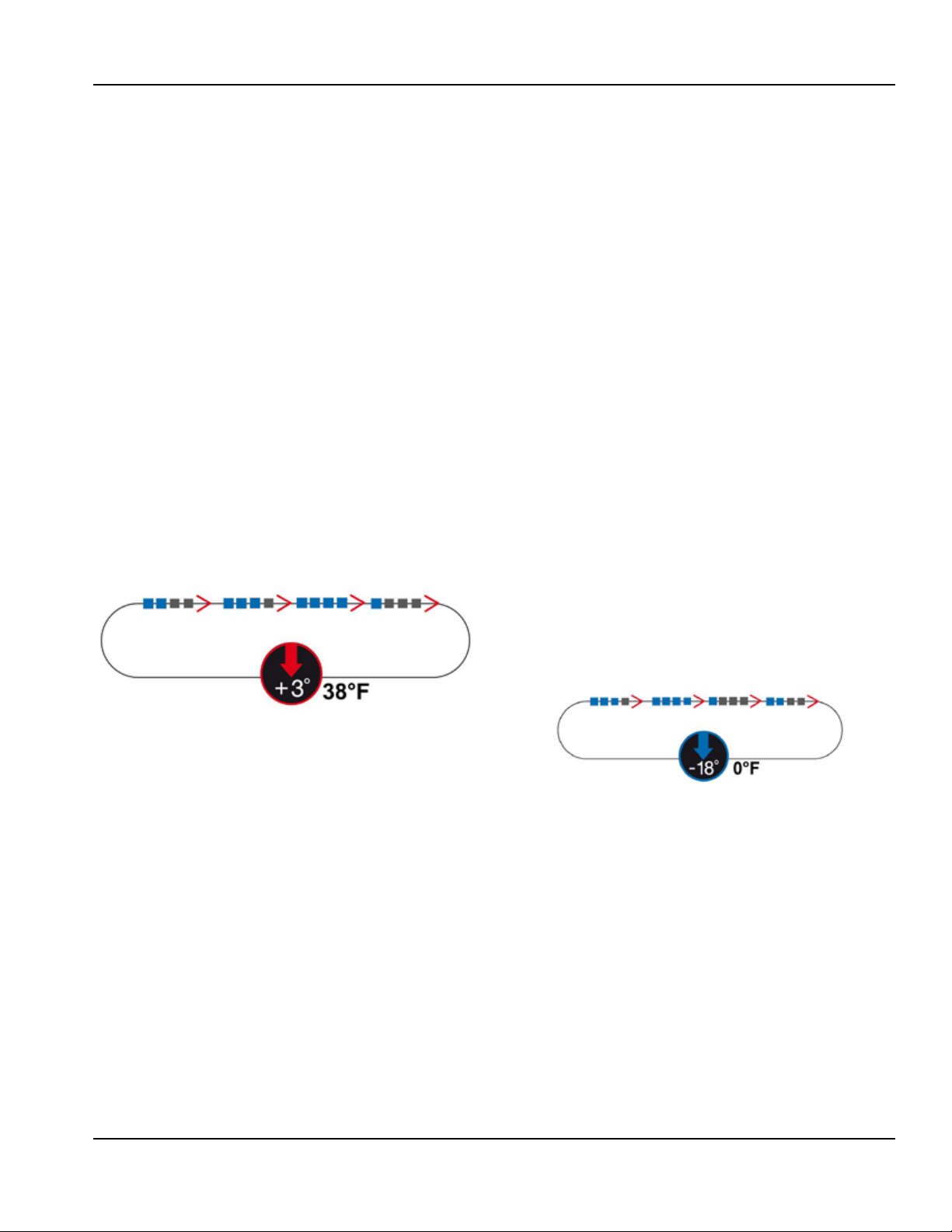
7.4 - Selection and starting the Negative chilling cycle
“LIGHT” - 1 LED only on
In this condition, there will be a cell temperature set of
27F (-3C). This avoids the risk of ice formation during the
positive chilling phase and it will be used for loads which
can be damaged by excessively heavy treatment.
“SOFT” - 2 LEDs on (default)
In this condition, there will be a cell temperature set of 23F
(-5C). This set will allow quicker chilling for products that
in any case are fairly resistant to the freezing process.
“MEDIUM” - 3 LEDs on
In this condition, there will be an initial cell temperature
set of -4F (-20C); after the HARD time, this will be taked to
a cell temperature of 24F (-3C). This method accelerates
cooling in the presence of products that are resistant and
very hot initially.
“FAST” - 4 LEDs on
In this condition, there will be an initial cell temperature
set of -4F (-20C), after the HARD time, this will be taken to
a cell temperature of 23F (-5C). This method accelerates
Pressing the button (3) for the first time will select the
“HARD” mode, represented by coming on of three of the
four LEDs (23) present. Subsequent pressing will take to
4 the LEDs lit and will return into “RUN+HARD” mode.
Successive presses reduce from 4 to 1 the LEDs and so on.
“LIGHT” - 1 LED only on
In this condition, there will be a cell temperature set of
23F (-5C); after the SOFT time defined by the parameter
(ts) this will move to a temperature of -22F (-30C). This
mode is for use on large pieces where it is important to
homogenise the chilling cycle.
“SOFT” - 2 LEDs on
In this condition, there will be a cell temperature set of
-4F (-20C); after the SOFT time defined by the parameter
(ts) this will move to a temperature of -22F (-30C). This
mode is for use on large pieces where it is important to
homogenise the chilling cycle.
In the case of SOFT or LIGHT temperature chilling, the
set change will be decided by the product temperature
detected according to the parameter (C2).
Part Number: 9294045 07/19 13
 Loading...