

Welbilt Delfield CV5E, Delfield CV10E, Delfield T40, Delfield CV15E-2, Delfield CV15E Original Instructions Manual
Page 1
Fresh Solutions, Fit for You
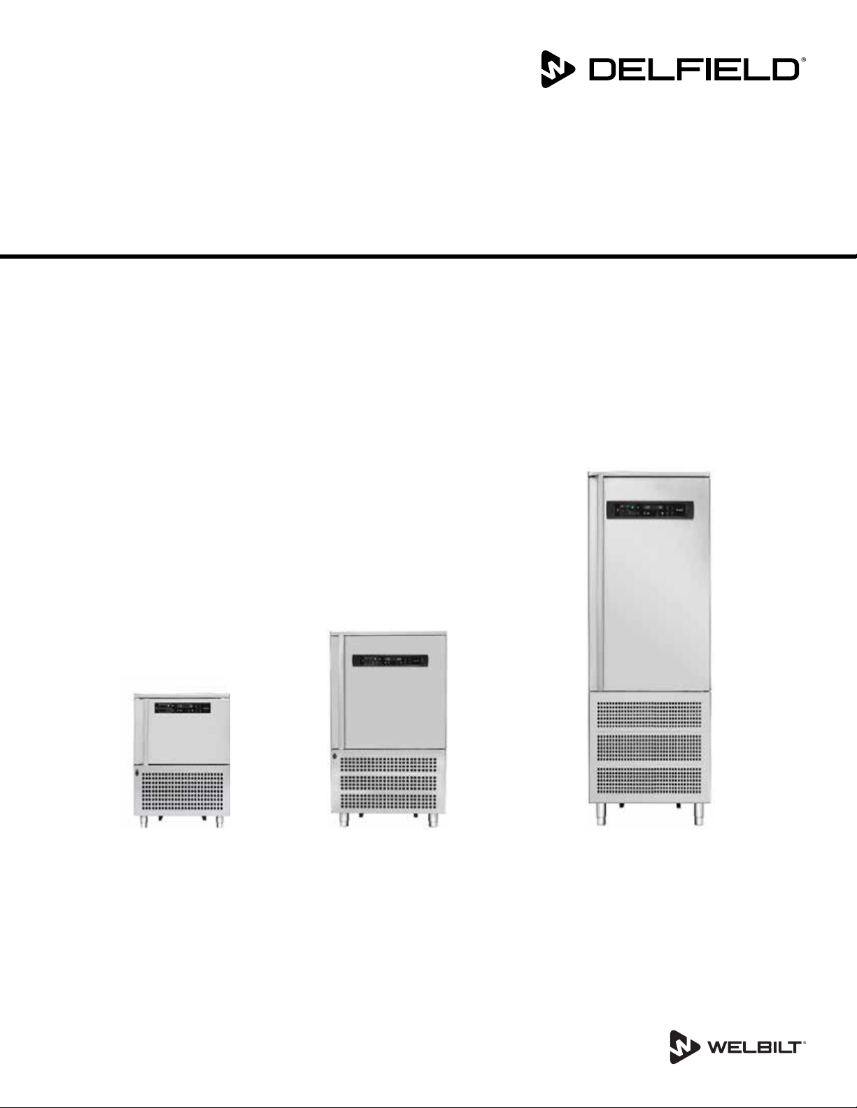
Blast Chillers
CV5E, CV10E, CV15E, CV15E-2 and T40
Original Instructions
Installation, Operation and Maintenance Manual
This manual is updated as new information and models are released. Visit our website for the latest manual.
Part Number: 9294045 07/19
Page 2

1 WARNINGS AND IMPORTANT ADVICE
2 TECHNICAL DATA
2.1 - Plate data
2.1 - Refridgerant
2.3 - Measurements
2.4 - Maximum loads
2.4.1 - Max load for internal structure capacity
2.4.2 - Max tray capaity
3 INSTALLATION
3.1 - Transportaion and handling
3.2 - Unpacking and disposal
3.3 - Positioning
3.4 - Ambient temperature and air exchange
3.5 - Hydraulic connection for water cooled units
3.6 - Electrical connection
3.7 - Remote group refrigerator connection
3.8 - Condensate drainage connection
3.9 - Notes for the installer
3.10 - Commissioning
3.11 - Safety and control systems
3.12 - Stop modes
3.13 - Signaling/reports of malfunction
3.14 - Appliance disposal
4 COMMAND INTERFACE SYMBOLS
5 MACHINE ON/OFF
5.1 - Compressor preheating management
6 DATE AND TIME SETTINGS
7 BLAST CHILLING CYCLES
7.1 - General chilling principles
7.1.1 - Chilling time
7.1.2 - Temperature chilling
7.1.3 - Chilling and storage status symbols
7.2 - Chilling phases
7.3 - Selecting and starting the pos. chill cycle
7.4 - Selecting and starting the neg. chill cycle
7.5 - Storage phases
8 DEFROST MODE
9 DRYING WITH MACHINE AT STANDSTILL
10 DOOR OPENING
11 OZONATOR
12 ICECREAM CYCLE
13 THAWING CYCLE
14 CHILLING PROGRAM STORAGE
15 CHILLING PROGRAM EXECUTION
16 ALARMS
10
10
10
10
10
11
12
12
12
12
12
12
12
12
13
13
13
14
14
14
14
15
15
15
16
16
16
2
5
5
5
6
7
7
7
8
8
8
8
9
9
9
9
9
9
16.1 - Evaporator probe alarm
16.2 - Product probe alarm
16.3 - Cell probe alarm
16.4 - Door micro-switch alarm
16.5 - Alarm - Diff. Thermal Breaker - Oil Pressure
16.6 - Auto reset minimum pressure swtich alarm
16.7 - Auto reset Kriwan Alarm
16.8 - Input alarm HT 1 - Fusable
16.9 - Overtemperature
16.10 - Black-Out Alarm
16.11 - Compressor preventative maint. alarm
16.12 - Temperature not reached in time alarm
16.13 - Power keypad-card connection alarm
16.14 - Maximum pressure switch alarm
17 HACCP ALARM MEMORIES RESET
18 HACCP DATA READING
19 HACCP DATA EXPORT WITH USB
19.1 - Extracted data format
19.2 - Data downloading with USB
20 ORDINARY MAINTENANCE
20.1 - Operations by the user that do not require
assistance of a qualified technician
20.1.1 - Cell cleaning
20.1.2 - Outer case cleaning
20.1.3 - Defrost water drainage
20.2 - Operation only for authorised installer
20.2.1 - Condenser cleaning
20.2.2 - Condenser filter cleaning
20.2.3 - Evaporator cleaning
20.2.4 - Ozonator maintenance
21 TIPS FOR SMOOTH OPERATION
21.1 - Operating instructions
21.2 - Pre-cooling
21.3 - Maximum load capacity for chilling/freezing
cycles
21.4 - How to load the machine
T40 information
1 UNIT INFORMATION
1.1 - Freezer Remote condensing unit details
1.2 - Remote water cooled condensing unit
1.3 - T5/T14D Refrigeration system schematic
1.4 - Wiring diagram
2 T40 INSTALLATION AND ASSEMBLY
2.1 - Supplied Equipment list
2.2 - Install and assembly instructions
3 - Controller buttons
4 -Controller functions
5 - Programming instructions
5.1 - Starting up the appliance
16
16
16
17
17
17
17
17
17
18
18
18
18
18
18
18
19
19
19
20
20
20
20
20
20
20
20
20
20
20
20
20
21
21
22
23
23
24
25
26
27
27
28
31
32
33
33
2 Part Number: 9294045 07/19
Page 3

Table of Contents
5.2 - Soft blast chilling by temperature
5.3 - Soft timed blast chilling
5.4 - Hard blast chilling by temperature
5.5 - Hard timed blast chilling
5.6 - Blast freezing by temperature
5.7 - Timed blast feezing
6 APPLIANCE FUNCTIONS
6.1 - Date and time settings
6.2 - Ice cream surface hardening
6.3 - Muting the beeper and alarm
6.4 - Program storage
6.5 - Displaying the three latest HACCP alarms
6.6 - printing out stored data
6.7 - Forced ventilation function
6.8 - Manual defrosting
6.9 - Automatic defrost cycles
6.10 - Printer operation
7. ALARM MANAGEMENT
7.1 - Storage of data/errors
7.2 - Software controls
33
34
34
35
35
36
37
37
37
37
37
37
37
38
38
38
38
39
39
39
Part Number: 9294045 07/19 3
Page 4

Safety Notices
Warning
n
Read this manual thoroughly before operating, installing
or performing maintenance on the equipment. Failure
to follow instructions in this manual can cause property
damage, injury or death.
DANGER
Do not install or operate equipment that has been
misused, abused, neglected, damaged, or altered/
modified from that of original manufactured
specifications.
DANGER
Keep power cord AWAY from HEATED surfaces. DO NOT
immerse power cord or plug in water. DO NOT let power
cord hang over edge of table or counter.
DANGER
All utility connections and fixtures must be maintained
in accordance with Local and national codes.
Warning
n
Authorized Service Representatives are obligated to
follow industry standard safety procedures, including,
but not limited to, local/national regulations for
disconnection / lock out / tag out procedures for all
utilities including electric, gas, water and steam.
Warning
n
Do not store or use gasoline or other flammable vapors
or liquids within or in the vicinity of this or any other
appliance. Never use flammable oil soaked cloths or
combustible cleaning solutions, for cleaning.
Warning
n
Do not use electrical appliances inside the food storage
compartments of the appliance, unless they are of the
type recommended by the manufacturer.
Warning
n
Use caution when handling metal surface edges of all
equipment.
Warning
n
This appliance is not intended for use by persons
(including children) with reduced physical, sensory
or mental capabilities, or lack of experience and
knowledge, unless they have been given supervision
concerning use of the appliance by a person responsible
for their safety. Do not allow children to play with this
appliance.
Caution
,
Use caution handling, moving and use of the R290
refrigerators to avoid either damaging the refrigerant
tubing or increasing the risk of a leak. Components
shall be replaced with like components. Servicing shall
be done by a factory authorized service personnel to
minimize the risk of possible ignition due to incorrect
parts or improper service.
Notice
Proper installation, care and maintenance are
essential for maximum performance and trouble-free
operation of your equipment. Visit our website www.
wbtkitchencare.com for manual updates, translations,
or contact information for service agents in your area.
Warning
n
This product contains chemicals known to the State
of California to cause cancer and/or birth defects or
other reproductive harm. Operation, installation, and
servicing of this product could expose you to airborne
particles of glasswool or ceramic fibers, crystalline
silica, and/or carbon monoxide. Inhalation of airborne
particles of glasswool or ceramic fibers is known to the
State of California to cause cancer. Inhalation of carbon
monoxide is known to the State of California to cause
birth defects or other reproductive harm.
Page 5
Section 2 Technical Information
2 TECHNICAL DATA
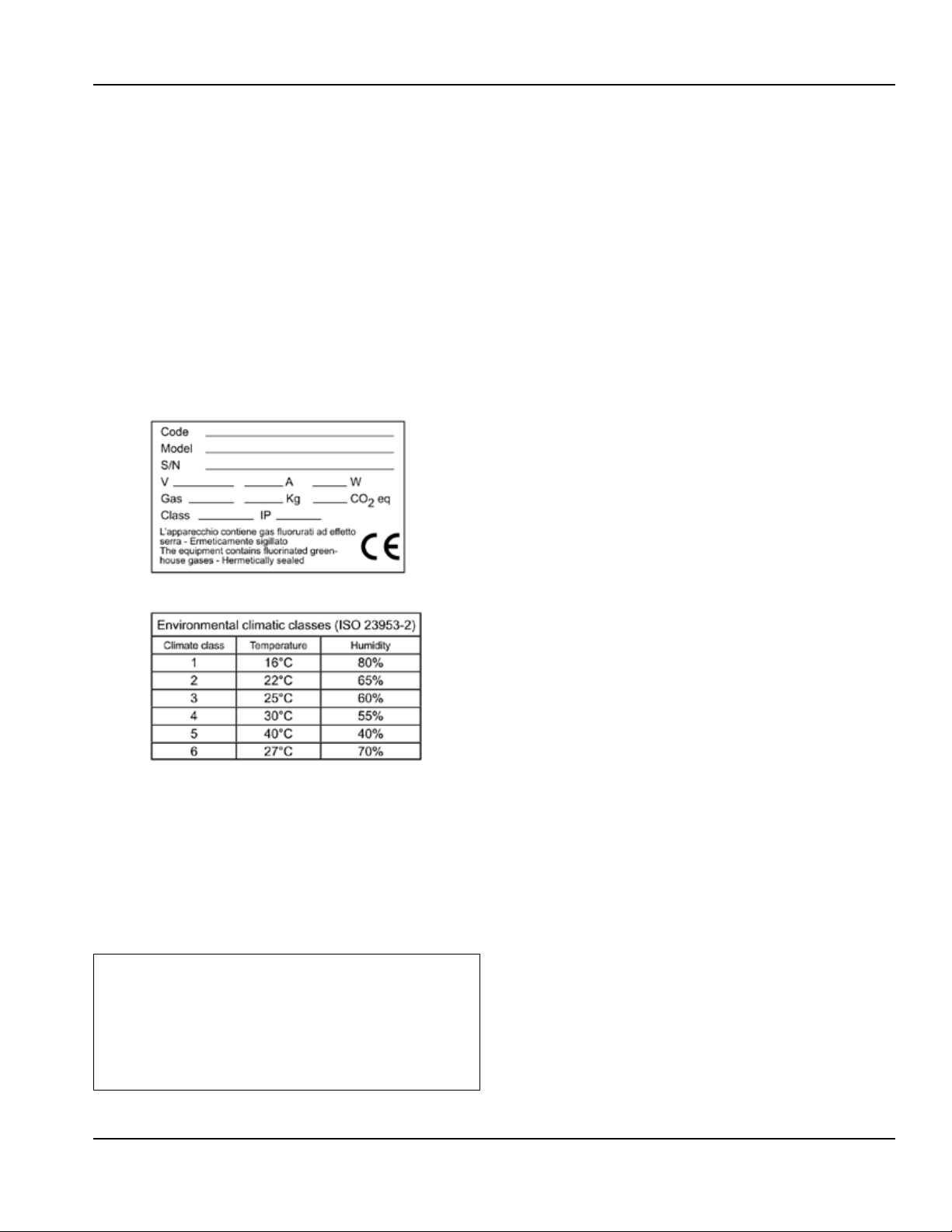
2.1 - Plate data
The plate bearing the equipment specifications should
be applied on the outside rear part of the machine and/
or on the electrical panels. Any preparation of machines
only for relocation of the condensing units must follow
the regulations enforced in the country of installation
regarding fire safety (refer to the command of the local
fire department for the relevent indications). It should
also be considered that the possible intervention of safety
valves or fusible plugs, located in the refrigerant circuit,
entail the immediate discharge of all the refrigerant into
the environment.
The appliance’s climate class is stated on the serial plate
2.2 - Refrigerant
The appliance contains flourinated greenhouose gases
covered by the Kyoto Protocol in the quantities indecated
on the serial plate. The type of refrigerant gas present in
the refrigerant circuit of the appliance is shown on the
serial plate. The GWP (global warming protential) of the
HFC R134a gas is 1430 and the HFCR404A gas is at 3922.
The CO2 equivalent data is shown on the serial plate.
,
According to regulation (EC) 1272/2008,
,
R134a and R404A gases are non-flammable
and non-toxic. in high concentrations they
cause burns and frostbite. in the system the
gas is pressurised; it may explode if heated.
Part Number: 9294045 07/19 5
Page 6
Technical Information Section 2
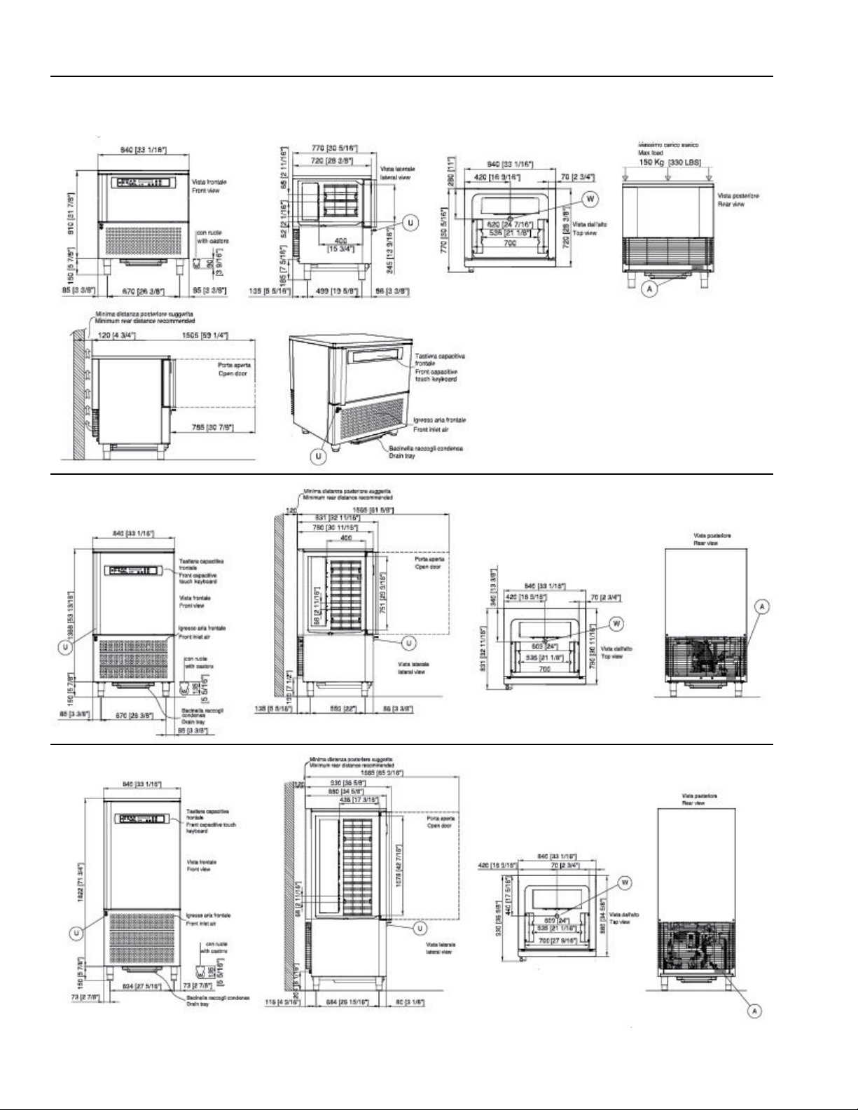
2.3 - Measurements
CV5E - 5 trays
CV10E - 10 trays
CV15E - 15 trays
6 Part Number: 9294045 07/19
Page 7
Section 2 Technical Information
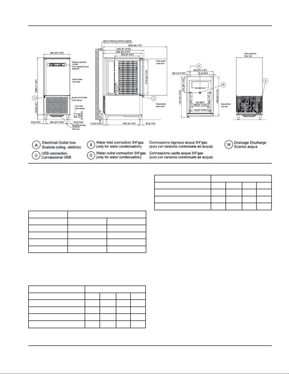
CV15E-2 - 30 trays
2.4 - Maximum load
,
Operators are strongly suggested to follow
enclosed instructions
2.4.1 - Maximum load for internal structure capacity
Maimum Capacity
Model Internal structure load per shelf
5T 1000oz (30kg) 700oz (20kg)
10T 1600oz (45kg) 700oz (20kg)
15T 2800oz (80kg) 700oz (20kg)
30T 3000oz (85kg) 700oz (20kg)
2.4.2 - Maximum trays capacity
(trays not supplied with the appliance)
Standard internal support structure
Model
Size Trays 5t 10T 15T 30T
15¾” x 23⁄” (600x400mm) 5 10 15 30
12¾” x 20¾” (530x325mm) 5 10 15 30
23⁄” x31½” (600x800mm) n/a n/a n/a 15
12¾” x 41½” (530x650mm) n/a n/a n/a 15
Optional internal support structure
Model
Size Trays 5t 10T 15T 30T
18” x 26” (655x453mm) n/a n/a n/a 15
12¾” x 20¾” (530x325mm) n/a n/a n/a 28
12¾” x41½” (530x650mm) n/a n/a n/a 14
Part Number: 9294045 07/19 7
Page 8
Technical Information Section 2
3 INSTALLATION
,
All stages of installation must be carried out in
,
compliance with the national standards in force
according to the manufacturer’s instructions and
by professionally qualified personnel.
Installation of the appliance and of the refrigerating
unit must only be carried out by technicians of the
manufacturer or by skilled personnel.
If the machine was supplied with a remote condesing
unit, it is the installer’s responsibilty to check all the
connections in accordance with the instructions provided
for the installation of the systems and machinery.
The installer is advised to use the appropriate personal
protective equipment necessary for processing and in
compliance with the regulations in force.
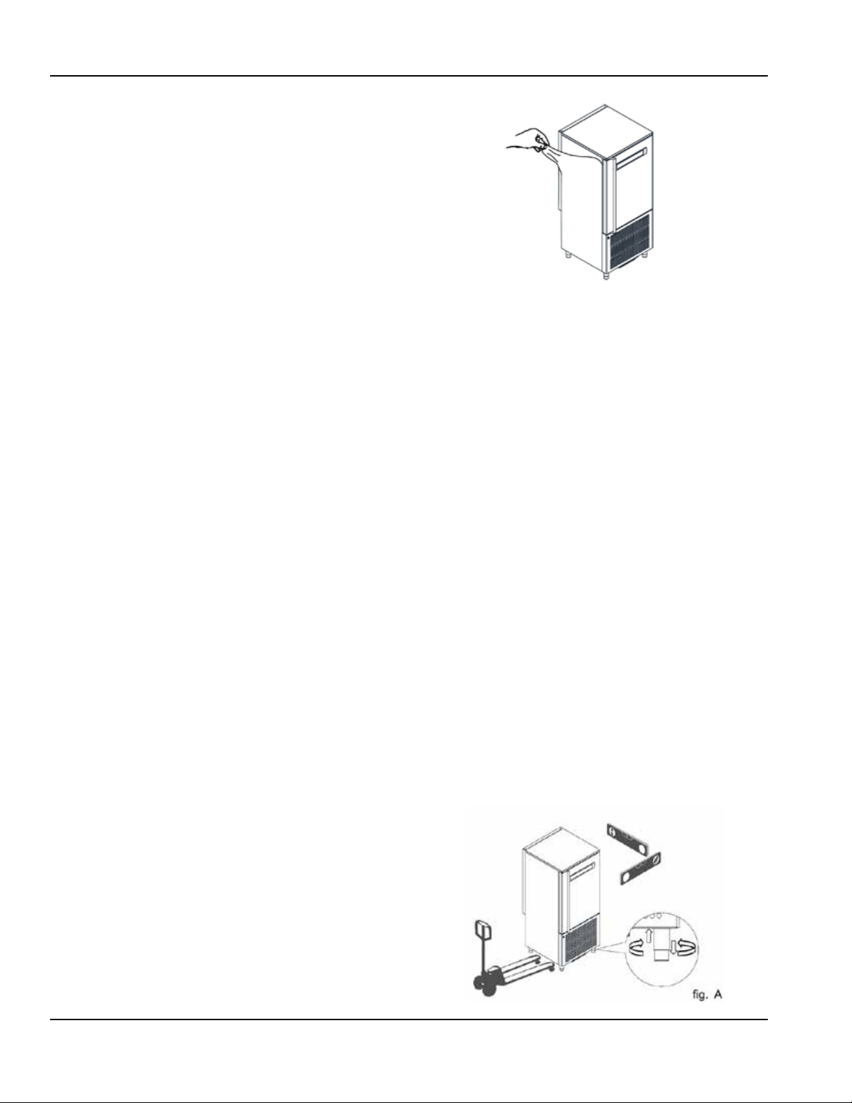
3.1 - Transportation and handling
The net and gross weight of this appliance can be found
on the external packaging.
Loading and unloading of the appliance and/or of the subsystems from the means of transport can be performed
using a forklift truck or fork pallet truck, the length of
which is more than half that of the unit or using cranes
where the apppliance/sub-system is fitted with eyebolts.
The lifting equipment must be chosen according to the
size of the packaged machine/components and with
sufficient capacity. For handling of the appliance/subsystems, every precaution must be taken not to damage
them, respecting the indications on the packaging.
3.2 - Unpackaging and disposal
Remove all cardboard or the wooden crate from the base
on which the machine is placed. Then lift the machine/
sub-assemblies with a suitable means (forklift truck);
remove the wooden base and position the machine/subassemblies in the place provided.
After removing the packaging, verify the integrity of the
machine/sub-assemblies in case of uncertainty do not use
it and contact the distributor.
Remove the protective PVC film on the stainless steel
panels from all sides both internally and externally.
NOTE: All the various components of the packaging must
be disposed of according to the regulations in force in the
country where the appliance is being used. In any case
nothing must be disposed of into the environment.
3.3 - Positioning
The appliance:
• must be installed in places where it can be checked by
qualified personnel
• it must not be installed outdoors.
• it must not be installed in dusty environments.
• it must not be placed in locations with the presence of
water jets.
• it must not be washed with water jets.
• it must be installed and tested in full compliance with
safety laws, traditional systems and with the regulations
in force.
• it must be positioned at a minimum distance of 120mm
from the rear wall.
The installer must verify any requirements for fire safety
(refer to the command of the local fire department for the
relevant indications.)
Level the appliance through adjustment of the feet. For
the setting up of heavier machines, use dedicated hoists
(fig. A - chap. 3.1).
If the appliances are not levelled their functioning and the
flow of condensates could be impaired.
8 Part Number: 9294045 07/19
Page 9
Section 2 Technical Information
,
Avoid:
• direct exposure to sunlight;
• closed sites with high tempuratures and poor air
circulation;
• indoor environments at high temperatures and poor air
circulation, and avoid installing the machine near any
heat sources
3.4 - Ambient temperature and air exchange
For air cooled liquid chillers, the ambient operating
temperature must not exceed 90°F (32°C). Above this
temperature the declared performance is not guaranteed.
The machine can operate safely up to a temperature that is
referref to by the climate class indicated on the serial plate.
Remote condensing units must be instaled in special rooms
or, if outdoors, in a place protected from direct sunlight,
from adverse weather conditions and from heavy wind
(above 5m/sec). Where circumstances so require, it is the
responsibility of the installer to evaluate the use of a cover
or canopy (costs to be borne by the purchaser). In any case
sufficient air circulation must be guaranteed.
3.5 - Hydraulic connection for water cooled condensing
units
It is advisable to install a valve between the mains and
the appliance’s inlet hose in order to be able to stop the
passage of water if necessary.
For appliances with water cooled units the water supply
temperature must be between 50°F (10°C) and 86°F (30°C)
and the operating pressure must be between 0.1 MPa (1 bar
- 14psi) and 0.5 MPa (5 bar - 72 psi).
regulations in the country of installation.
The electric connecting cables must be dimensioned
in accordance with the rules in force in the country of
installation. In cases wwhere the power cord of the
appliance is damaged, it must be replaced with another
with characteristics that comply with the rules in force in
the country of installation and performed by a qualified
personnel in order to prevent any risk to persons.
The earthing conductor must be correctly connected to
an efficient earthing system.
The manufacturer declines any responsibility and any
warranty obligation in the event of damage to the
equipment, to persons and property caused by incorrect
installation and/or failure to respect the applicable laws.
3.7 - Remote group refrigerator connection
The diameters of the supply lines of the equipment
are sized for distances of up to 10 meters. Contact the
manufacturer for longer distances.
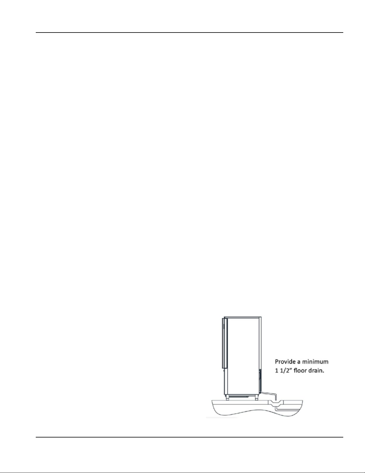
3.8 - Condensate drainage connection (if applicable)
It is necessary to provide a drainage pipe for the
condensation and washing water of a minimum diameter
of 1”. It is advisable to dispose of the condensate through an
open drain at ground level and fitter with a siphon with a
minimum diameter of 1/2”.
3.9 - Notes for the installer
• Verify the correct installation and system testing before
starting up the machine (test report).
• Check for any gas leaks from the welds or joints made
during the installaition phase.
3.6 - Electrical connection
No responsibility is accepted for damage to
,
persons, animals or property cause by failure
to earth the appliance and the creating of an
electrical installation that does not comply with
current standards.
The mains connection must be made according to existing
national rules and by experienced, qualified personnel.
Before connecting the appliance to the mains make
sure that the mains voltage corresponds to the voltage
indicated on the data plate.
Verify that the electrical installation is adequate to the
maximum power of the appliance, as indicated on the
plate. Upstream of each device it is mandatory to install
a differential thermal breaker according to current
Part Number: 9294045 07/19 9
Page 10

Technical Information Section 2
• Check the efficient insulation of the connecting pipes
between the condenser and the remote condensing
unit.
• Check the electrical connection
• Check the electrical input
• Verify the standard pressures of the refrigerating system
• Check the water connections with adjustment of the
pressure valve during operation and good circulation of
the condensation water (water cooled groups).
3.10 - Commissioning
Commissioning must be carried out by
,
authorised and qualified personnel.
Perform at least one complete cycle of rapid storage
freezing (to reach the SET temperature), and a manual
defrost cycle. If the equipment or the remote condensing
units were delivered in an upright position (e.g. on their
back) or were overturned during installation, do not turn
on immediately but wait at least 4 hours before use.
Inform the customer of the exact use of the equipment
with specific reference to the use and to customer
requirements.
3.13 - Signalling/reports of malfunctioning
In cases of malfuntion of the machine and for report
signalling concerning the blast chillers supplied.
Assembled
You are requested to communicate to the retailer/service
center the machine model, code and the serial number
shown on the registration plate located on the rear of the
machine and inside the door.
Dismantled (with condesnsing units/remote
condensors)
You are requested to communicate to the retailer/service
center the machine model and the code shown on the
registration plate located above the control panel.
3.14 - Appliance disposal
After the useful life of the appliance has been realized be
sure to demolish and dispose of the machine in compliance
with the regulations applied in the country of installation,
particularly in regards to refrigerant gas and compressor
lubricant oil.
3.11 - Safety and control systems
• Door microswitch: this locks operation of the fans in the
cell when the door is opened.
• General protection fuses: they protect the entire power
circuit against short circuits and possible overloads.
• Compressor thermal relay: this intervenes in case of
overloads or malfunction.
• Safety pressure switch: this operates in the case of
excess pressure in the refrigerant circuit.
• Fusible plug: this intervenes in the case of overpressure
and failure of the afore-mentioned safety pressure
switch.
• Chamber temperature control: this is operated by the
electronic card via the probe positioned inside the cell.
• Defrost termination temperature control: this is
managed by the electronic card via the probe located
on the evaporator.
3.12 - Stop modes
In an emergency, to stop the machine remove power from
the main panel using the earthing switch or by removing
the plug from the socket making sure hands are not wet or
damp.
10 Part Number: 9294045 07/19
Page 11
Section 2 Technical Information
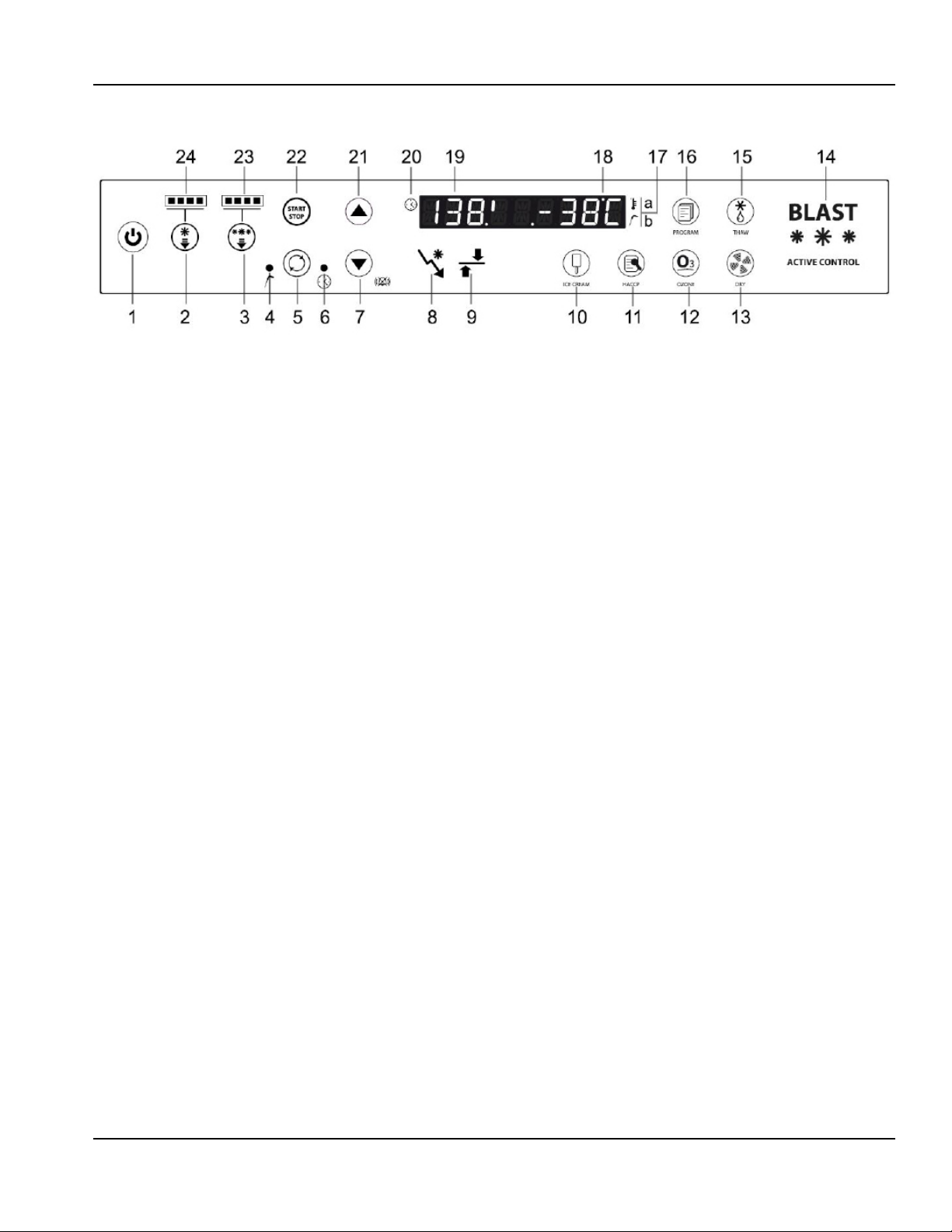
4 COMMAND INTERFACE SYMBOLS
1 - Stand-by button - Standby button, if pressed for more
than 3 seconds it takes the card into standby or switches
it on again.
2 - Positive chilling button - Used to select the mode of
positive chilling.
3 - Negative chilling button - Used to select the mode of
negative chilling.
4 - Chill. LED Temperature - LED on means that the chilling
is via tempurature mode (insert probe)
5 - Chilling mode button - A button that selects the mode
of chilling with Time or Temperature (insert prode use);
the selected mode is represented by ignition of one of the
two LEDs located on the right and left of the button and
the are marked with the temperature or time symbol.
6 - Chill. LED Time - LED on means that the chilling is via
Time mode
7 - Decrease button - Parameter or setting value decrease
buttons (the “-” button allows silencing of the beeper if
active.)
8 - Chilling phase LED - Symbol representing the chilling
phase (it flashes when at that phase.)
9 - Storage phase LED - Symbol representing the chilling
phase (it flashes when at that phase.)
10 - Ice-cream button - The ice-cream button which starts
the ice-cream cycle. (see section 12).
11- HACCP button - The HACCP button which starts the
data reversal cycle onto USB.
12 - Ozone button - Button that starts the ozone sanitising
cycle (if any).
13 - Defrost button - Button that when pressed once starts
drying with door oper (see section 9), while if pressed for
at least 3 seconds it starts the hot gas defrost cycle.
14 - Status LED - RGB on mark lettering. The lettering
assumes the following colors depending on the following
relative connected states:
BLUE - Phase of chilling, deep-freezing or storage
ORANGE - Thawing
GREEN/BLUE - Machine on stand by
WHITE - Machine at standstill
RED FLASHING - Serious alarm
FLASHING YELLOW - Non-serious alarm (door opening -
maintenance)
15 - Thawing button - Button that when pressed starts the
defrost cycle
16 - Program button - Programs recall or storage button
17 - Temperature symbol - The symbol lights up when a
cycle is active and the cell temperature (time chilling) or
product temperature (temperature chilling) is detected.
In the second case the product probe is shown with the
highest value. With the cycle in progress press the button
(12) to display in sequence the values of the insert probe
1 and 2 and the evaporator sensor probe in flashing mode
and the display (19) will show the letters in sequence SP1+
“probe value”, SP2+”probe value” and SE+”value”.
18 - Display temperature - Second part of the alphanumeric
desplay (last 4 digits) for representation of the T° cell or T°
product and evaporater value.
19 - Display time - First part of the alphanumeric display
(first 4 digits) for representation of the time value
remaining of chilling.
20 - Time symbol - The symbol lights up when the cycle
is running; the time remaining will be displayed. If the
button (5) is pressed the elapsed time will flash for 5
seconds (both for Time and Temperature chilling).
21 - Increase button - Parameter or setting value increase
buttons.
22 - Cycles start/stop button - start/stop the chilling cycle
set; with a cycle started, the button remains lit.
23 - Negative chilling LED - The number of LEDs lit indicates
the intensity of the negative chilling.
24 - Positive chilling LED - The number of LEDs lit indicates
the intensity of the positive chilling.
Part Number: 9294045 07/19 11
Page 12

Technical Information Section 2
5 MACHINE ON/OFF
When the equipment is powered, it will appear in
STANDBY conditions (scrolling text on the display). To start
the machine press the button (1) for at least 3”. Similar to
machine without cycles in progress, to switch it off simply
press the button (1) for at least 3”.
Where a cycle was in progress, and the situation is returning
from a blackout the appliance, once reconnected, will
resume from the interrupted cycle.
5.1 - Compressor preheating management
Upon ignition of the equipment a compressor preheating
time of 120 minutes must be respected where the blast
chiller is not available.
The scrolling text will appear “Compressor HeatingRiscaldamento Compressore” and then the fixed lettering
“XXX min” to represent the time remaining. These two
messages will alternate until the end of heating. This phase
can be bypassed by pressing the “HACCP” (11) button for
approximately 5 seconds.
6 DATE AND TIME SETTING
Upon initial ignition, it is advisable to check the date and
time set; their accuracy is beneficial in relation to HACCP
management.
To access the clock setting, press for more than 5 seconds
the Temperature/Time button (5) with the machine in
Stop mode. The laels shown below will appear on the left
display; the right display will show the 2-digit numeric
value to be set:
Hour(Ora) / Minute(Minuti) / Day(Giorno) / Month(Mese) /
Year(Anno)
The Temperature/Time button (5) can be used to scroll
through the labels, while with the +/- buttons (21/7) it is
possible to change the values.
After the year value the change will be automatically
saved.
7 BLAST CHILLING CYCLES
7.1 - General operating principles
Pre-cooling of the machine should always be performed
upon initial running of a blast chilling or deep freezing
operation. This optimises the subsequent work cycle,
reducing the time.
Blast chillers are refrigeration systems that work with a twophase cycle:
• Chilling phase (limited duration)
• Storage phase (unlimited period)
The chilling phase starts upon pressing of the “Start/Stop”
button (22) and continues until the end of the chilling
phase that is used to achieve the time set (Time chilling) or
for reaching of the product temperature set (Temperature
chilling); changing to the unlimited duration storage cycle
takes place automatically (except for the the HARD+HARD
negative chilling cycle). It is possible to stop the chilling
or storage at any time by pressing the “Start/Stop” button
(22).
Chilling time
During this type of chilling, the display (18) shows the cell
probe temperature while the other display (19) shows the
time remaining at the end of the chilling phase. The Time
chilling LED (6) is lit as is the time symbol (20).
Temperature chilling
If Temperature chilling is selected, at the start of a cycle a
check is performed of the correct insertion of the product
probe (if enabled). If the test provides a negative result
an alert appears on the display “SONDA NON INSERITA PROBE NOT INSERT” and the beeper sounds for 60 seconds
(parameter c9); that symbol disappears when the beeper
is silenced by pressing the button (7). If instead the button
is pressed again (5) switching to Temperature cycle, the
cycle continues based on the data read by the product
probe. If nothing is pressed, the temperature cycle
automatically switches into a Time cycle for the remaining
duration of the countdown.
During this type of chilling, a display (18) will show the
temperature of the probe (the highest value of the two)
and the other (19) will show a countdown. The countdown
only starts when the insert temperature is less than 149°F
(65°C). The temperature chilling LED (4) is on as is the
probe insert symbol (17).
Chilling and strorage status symbols
During chilling the LED that lights the sybol will be lit and
flashing. Upon completion of chilling, this LED flashes
alternately with the LED located beneath the storage
symbol (8) while the beeper sounds for 60 sec, and the
scrolling text appears “End Cycle - Fine Ciclo”. After this
time, the chilling LED (9) switches off, the storage one
starts flashing (8) and the scrolling text disappears (even
when the beeper silencer button (7) is pressed.
The LED (8) will flash when the compresser is on while if
the set value has been reached, they will only remain lit
until transition to storage. Similarly with storage, the LED
(9) will flash when the compressor is active and will remain
lit for the rest of the storage.
12 Part Number: 9294045 07/19
Page 13
Section 2 Technical Information
7.2 - Chilling phases
Pressing the positive chilling button (2) or negative
chilling button (3) allows selection of a different chilling
mode. The number of LEDs lit (23) or (24) define the
“intensity” of chilling. The “Time” or “Temperature” chilling
mode will be set by pressing the button (5). Lighting up of
the corresponding LEDs on the sides will define the type
of chilling.
Each time the positive chilling button (2) is pressed the
display will show successively for 3 seconds one of the
following cycles:
LIGHT, SOFT, MEDIUM, FAST.
Each time the negative chilling button (3) is pressed the
display will show successively for 3 seconds one of the
following cycles:
LIGHT, SOFT, HARD, RUN.
7.3 - Selecting and starting the positive chilling cycle
When the button (2) is pressed for the first time, “SOFT”
mode will be selected, represented with lighting up of
two of the four LEDs (24); subsequent pressing takes to 3
and 4 LEDs lit and results in the “HARD” mode. Successive
pressing reduces from 4 to 1 the LEDs lit and so on.
cooling in the presence of products that are resistant and
very hot initially.
Once the MEDIUM or FAST cycles are started, to modify the
HARD phase duration simply press the button (2) that will
show on the display (19) the words “Hard” and will result
in flashing on the display (18) the value in minutes of the
HARD phase. With the +/- buttons it is possible to increase
or decrease the value and confirm with the button (2) or
wait 5 seconds (N.B. THE CHANGED VALUE ONLY APPLIES
TO THE CYCLE IN PROGRESS).
Once the cycle is selected, it is necessary to select the Time
or Temperature mode by pressing the button (5) until
coming on of the relevant LED.
At this point to start the cycle press the START/STOP
button (22).
In the even of Temperature chilling, it is possible to
change this chilling end value by pressing the button (2)
or (3) depending on the type of chilling in process. Having
pressed the button, the display (18) will appear the value
of the end chilling temperature set, which can be modified
within the envisaged range. Having pressed the button (2)
or (3) or after 5 seconds the changed value is saved.
7.4 - Selection and starting the Negative chilling cycle
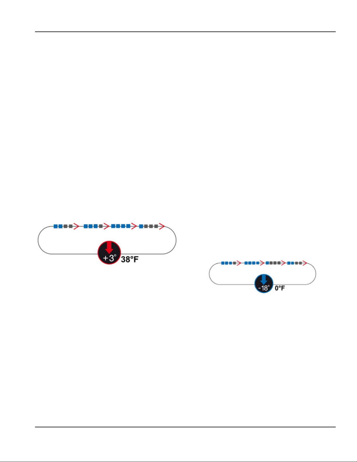
“LIGHT” - 1 LED only on
In this condition, there will be a cell temperature set of
27F (-3C). This avoids the risk of ice formation during the
positive chilling phase and it will be used for loads which
can be damaged by excessively heavy treatment.
“SOFT” - 2 LEDs on (default)
In this condition, there will be a cell temperature set of 23F
(-5C). This set will allow quicker chilling for products that
in any case are fairly resistant to the freezing process.
“MEDIUM” - 3 LEDs on
In this condition, there will be an initial cell temperature
set of -4F (-20C); after the HARD time, this will be taked to
a cell temperature of 24F (-3C). This method accelerates
cooling in the presence of products that are resistant and
very hot initially.
“FAST” - 4 LEDs on
In this condition, there will be an initial cell temperature
set of -4F (-20C), after the HARD time, this will be taken to
a cell temperature of 23F (-5C). This method accelerates
Pressing the button (3) for the first time will select the
“HARD” mode, represented by coming on of three of the
four LEDs (23) present. Subsequent pressing will take to
4 the LEDs lit and will return into “RUN+HARD” mode.
Successive presses reduce from 4 to 1 the LEDs and so on.
“LIGHT” - 1 LED only on
In this condition, there will be a cell temperature set of
23F (-5C); after the SOFT time defined by the parameter
(ts) this will move to a temperature of -22F (-30C). This
mode is for use on large pieces where it is important to
homogenise the chilling cycle.
“SOFT” - 2 LEDs on
In this condition, there will be a cell temperature set of
-4F (-20C); after the SOFT time defined by the parameter
(ts) this will move to a temperature of -22F (-30C). This
mode is for use on large pieces where it is important to
homogenise the chilling cycle.
In the case of SOFT or LIGHT temperature chilling, the
set change will be decided by the product temperature
detected according to the parameter (C2).
Part Number: 9294045 07/19 13
Page 14

Technical Information Section 2
Once the cycle to change the duration of the SOFT phase
is started (never greater than the parameter C4) simply
press the button (3) which will show on the display (19)
the wording “Soft” and on the display (18) the value in
minutes of the SOFT phase. With the +/- buttons, it is
possible to increase or decrease this value and confirm it
with the button (3) or wait 5 seconds (N.B. THE CHANGED
VALUE ONLY APPLIES TO THE CYCLE IN PROGRESS).
In the case of temperature chilling, the set changes will
be decided by the product temperature detected (see
paramerer cd).
“HARD” -3 LEDs on (Default)
In this condition and in the absence of adjustments 0.10V
of the compressor, there will be a set cell temperature of
-40°F (-40°C). This set accelerates the freezing process in
the presence of products that do not require particular
preperation.
“RUN” -4 LEDs on flashing
In this condition and in the absence of adjustments 0.10V
of the compressor, there will be a set cell temperature of
-40°F (-40°C). This set accelerates the freezing process in
the presence of products that do not require particular
preperation. In this case then the deep-freezing cycle will
be continuous without moving into storage. The move
to storage will be performed by pressing the button (3)
and reducing the LEDs from 4 to 3. That process should
be used in continous insertion and extraction condition
produced by the blast chiller.
During negative chilling, the compressor stops when the
air temperature reaches the planned set point. In this
cycle there will NOT BE automatic defrosting.
- Probes value reading
With the cycle in progress, pressing the button (12) will
chow in sequence, after the cell probe value, the values
of the insert probe 1 and 2 and the evaperator probe in
flashing mode on the display (18) while on the display (19)
will appear the wording in sequence of SP1, SP2 and SE
that represent the type of probe being displayed.
7.5 - Storage phase
Storage always takes over and automatically after every
chilling event (apart from the negative RUN+HARD
exception) and keeps the product at the storage
temperature of 35.6°F (2°C) or -13°F (-25°C), depending on
the typre of chilling.
These values will be editable in all cases by pressing
the button (2) or (3). It is possible to change during the
storage phase the temperature set which appears flashing
on the display (18), while on the display (19) the wording
SET appears. To adjust the value (within 6 seconds) press
the buttons +/-.
8 DEFROST MODE
“Gas-hot” or “air” defrosting takes place:
- in automatic mode only during the storage phase and
with a default time of 8 hours that is editable - or -
- manually both with machine in storage and with machine
in STOP (not during chilling) by pressing the defrost
button (13). All defrosting in progress can be interupted
by pressing the defrost button.
Duration of the defrost cycle is given by reaching the
defrost end temp measured by the evaporator probe;
there is in any case a maximum length for defrost after
which defrosting ends automatically.
Whenever possible, namely during the cycles of chilling,
of ice-cream hardening, of storage, defrosting in storage
and defrosting at machine standstill, it is possible to view
the evaporator probe temperature by pressing the button
(12): the display will show fo r5 seconds the wording “S.EV
+ valore”.
Manual defrosts cannot be activated in the event that
the value of the evaporator probe is higher than a certain
temperature value, in which case a series of beeps will be
emitted to alert the user to the fact that it is not possible
to defrost and the wording “NoDefrost” will appear for 5
seconds.
9 DRYING WITH MACHINE AT STANDSTILL
When the machine is stopped by pressing the button (13)
for more than 3 seconds, ventilation will be activated for
a maximum time of 20 minutes (either with door open
or closed). During this function the LED flashes and the
display shows the scrolling text “Air Defrost”. To exit from
this function press (short press) the defrost button (13).
This mode is used when the machine is at a standstill for
air defrost or to dry the machine after cleaning.
10 DOOR OPENING
When the machine is running (chilling, storage, defrost),
the door is opened, the display shows the scrolling text
“DOOR OPEN” every 5 seconds, alternating with the value
read, and the beeper emits beeps.
When closing the door, the fan starts without delays.
If the machine is running the door remains open for
more than 5 minutes, the fan does NOT start again. The
compressor is also locked and the open door alarm is
given. Door reclosing, resetting of the audible alarm,
visual and alarm relay.
If the door is opened while the machine is in “stop” the
beeper does not sound but the appearance of the wording
DOOR OPEN continues.
14 Part Number: 9294045 07/19
Page 15

Section 2 Technical Information
11 OZONATOR
This function is only available when the machine is
stopped and is activated by pressing the ozonation
button (12) (the LED of the button comes on) . The ozone
is released for 120 minutes after which the release ends
(the LED goes off). At the same time as the Ozonator the
fan is also activated to facilitate movement.
During the sterilisation cycle the word “Ozone” will
flash on the display (18) and the display (19) will show
the countdown of the cycle time. If the door is opened
during the 120 minutes, the sterilisation cycle will stop
IMMEDIATELY; it will not even start upon closing of the
door, and the scrolling text “STOP Ozone Cycle” will appear
for 5 seconds. If the ozonator is not installed the scrolling
text “Ozone Not Present - Ozone non presente” will appear
on the display for 10 seconds.
12 ICECREAM CYCLE
This cycle enables the user to use the chiller in negative
chiller mode with a Timer that schedules the introduction
and extraction of ice-cream containers, allowing the
surfaces to harden, after leaving the ice-cream making
machine.
With the machine in stop mode, press the “ice-cream”
button (10); the beeper will emit a beep and the LED of
the button will start to flash. The negative chilling cycle
will start immediately (to cool the machine), the display
(19) of the time will show the flashing cycle time while
the display (18) will indecate the tempetature of the cell
probe.
The user has the option,n at this point, to modify the time
of the hardening cycle by pressing the “+” and “-”, and to
confirm the time by pressing the “ice-cream” button (10).
After this setting when the user opens the door (to
introduce the ice-cream) and then reclose it, a beep is
emitted as comfirmation and the countdown will start.
When the time reaches zero, the beeper will sound for
60 seconds, and the sliding text “carica gelato - charge
ice cream” will appear. Then whenever the door is closed,
any countdown in progress is interrupted and a new one
starts.
During the cycle the user may at any time change the time
and the temperature set as default as follows:
1) by pressing the “ice-cream” button (10), with the first
time press the time on the display (19) will flash and it can
be changed with the +/- buttons.
2) the next press of the button (10) will acquire the new
value.
3) now using the buttons +/- it is possible to chance the
flashing set represented on the display (18) with a value
that can range from the minimum value to a maximum
one (this theoretically allows setting of the long softening
cycles for ice-cream which, extracted from the storage
machine, must be placed on display.)
4) pressing the button (10) allows saving of the new value
followed by the return to the cycle.
The user can stop this cycle at ay time by pressing the
START/STOP button (22).
13 THAWING CYCLE
This function aims to safely thaw (below 50°F (10°C)
of temperature cell) previously frozen or deep-frozen
products. The process is based both on cell temperature
control, with a positive value between 38°F (3°C) and 50°F
(10°C) average, and on the action of forced ventilation.
When the machine is stopped, select the thawing cycle by
pressing the button (15); the cycle will start immediately
showing on the “display 19” the standard thawing time
and on “display 18” the measured cell temperature.
To change the values of time and temperature set, simply
press the button (15) until the display flashes which
will present the time value set. With the +/- buttons it is
possible to modify the thawing time. With the modification
completed with the +/- buttons it is possible to change
the SET which will be confirmed by pressing the button (5)
or by waiting 5 seconds.
The the temperature set value flashes on the display (8)
which can also be changed with the +/- buttons. With
the modification completed with the +/- buttons (6) it is
possible to change the SET by pressing the button (3) or
by waiting 5 seconds.
Then on the display, if VE2 is different from 100, the
wording “HARD FANS” will be represented (if fan
regulation is enabled). To confirm press the button (5),
while to change press the +/- buttons until appearance
of the second option “SOFT FANS” (reduced evaporator
fan speed); pressing the button (5) the value selected is
confirmed.
After this operation, the cycle in fuction is resumed which
when finished will activate the beeper and the scrolling
text “End Cycle - Fine Ciclo” will appear. At that time the
cycle will go into storage.
To see the value of the insert probe during thawing, simply
press the button (12) which will display the product probe
value for 5 seconds flashing on the display (18) and the
wording “SP1” and “SP2” is shown on the display (19) to
distinguish the probe reading.
Part Number: 9294045 07/19 15
Page 16

Technical Information Section 2
14 CHILLING PROGRAM STORAGE
The user has the button (16), which allows the saving or
recalling of 99 chilling cycles.
To store a chilling cycle the user must:
1) set a chilling type (button 1 - 2)
2) set the mode of chilling (by temperature or by time,
button (5))
3) set the total time or the final temperature +/- buttons.
4) press and hold (long press) the “PROGRAM” button
(16) until the beeper emits a beep; the LED of the button
starts to flash. On the basis of the first display it will flash
signifying waiting for setting of the first letter/number.
5) then using the keys +/- set the first letter/number and
confirm with the button (5). This will confirm the value,
passing on to the next one. Arriving at the ninth character
or even before, it is possible to press the START button for
start and storage (ATTENTION, if a program with the same
name already exists, it will be overwritten.)
6) press START/STP (22)
With Start the software stores the “type” and “mode” of the
chilling selected.
To discontinue saving of the program, press the storage
button again or wait for the TimeOut (approximately 10
seconds). If time chilling has been set, the duration set is
stored.
In the case of temperature chilling, it will store the
time in which the insert probe reaches the PRODUCT
TEMPERATURE SET, and will store this time as durtion of
chilling.
In addition, if the chilling is Positive Hard, it also saves the
time necessary to reach the core at 68°F (20°C) (Hard).
When saving a temperature (insert probe) chilling cycle,
the LED of the programming button flashes to indicate
that storage of the times is in progress. As soon as the
temperature chiling cycle ends, the LED stops flashing to
indicate that storage has been successful.
If storing a temperature cycle, this stops (due to alarms,
button stop, etc.), the cycle times are not saved. The initial
settings however remain saved.
15 CHILLING PROGRAM EXECUTION
To call up and run a memory-resident program, the user
must:
1) press the “PROG” button (short press), the LED lights up
and with the +/- buttons, select one of the saved programs.
2) press START
If the save button is pressed by accident, pressing it again
will exit that function.
While a program is running, by pressing the “PROG” button
the display shows the name of the program in progress.
16 ALARMS
Summerized here are the main alarms that can appear
and that will be represented by the scrolling text on the
display:
16.1 - Evaporator probe alarm
Cause: being outside the operation range (-58°F (-50°C) /
212°F (100°C)) for more than 30 seconds.
Effect: Interruption of any defrosting in progress. Inhibition
of all periodic defrosting. Inhibition of manual defrosting
(except forcing of fans with machine at standstill).
Beeper: The beeper sounds (3 seconds then pauses for 30
seconds) until the silencer button is pressed.
Display: The display shows the scrolling text “AL01 SONDA EVAPORATORE DIFETTOSA - FAULT EVAPORATOR
PROBE”. Flashing RED symbol (14).
Reset: It resets by itself if the value of the probe falls
(approximately 20 seconds), or if the probe is excluded
with parameter “/5”.
16.2 - Product probe alarm
Cause: being outside the operation range (-58°F (-50°C)
/ 212°F (100°C)) for more than 30 seconds with a
temperature chilling cycle in progress.
Effect: Interruption of the temperature chilling cycle in
progress resulting in automatic start of Time chilling.
Inhibition of all periodic defrosting. Inhibition of
temperature chilling button.
Beeper: The beeper sounds (3 seconds then pauses for 30
seconds) until the silencer button is pressed.
Display: The display shows the scrolling text “AL02 SONDA PRODOTTO 1(2) DIFETTOSA - FAULT PRODUCT
PROBE 1(2)”. Flashing RED symbol (14).
Reset: Press the alarm silencer button (with beeper off)
or exclede with parameter “/9” (temperature chilling
disabled).
16.3 - Cell probe alarm
Cause: being outside the operation range (-58°F (-50°C) /
212°F (100°C)) for more than 30 seconds.
Effect: If START is given to a positive chilling (both with Time
and Temperature) or if the latter is already in progress, it
immediately goes into pause-work positive storage mode
(C5 and C6 parameters0
If START is given to a negative chilling (both with Time
16 Part Number: 9294045 07/19
Page 17

Section 2 Technical Information
and Temperature) or if the latter is already in progress, it
continues (as it is not conditioned by the cell temperature
until passing into negative storage which will be in pausework mode (C5 and C7 parameters)). If the event takes
over during storage, this continues in pause-work mode.
Beeper: The beeper sounds (3 seconds then pauses for 30
seconds) until the silencer button is pressed.
Display: The display shows the scrolling text “AL03 SONDA CELLA DIFETTOSA - FAULT ROOM PROBE”. Flashing
RED symbol (14).
Reset: It resets by itself if the value of the probe is activated.
NOTE: With cell probe anomaly it is in any case possible
to perform RUN+HARD chilling (compressor goes into
continuous mode).
16.4 - Door micro-switch alarm
Cause: Active input for more that 5 minutes (uF parameter)
with maching in start.
Effect: The blast chiller behaves as described in the section
“7 Door Opening 7”.
Beeper: The beeper sounds (3 seconds and then pauses
for 30 seconds) until the silencer button is pressed.
Display: The display shows the scrolling text “PORTA
APERTA - DOOR OPEN”. The symbol (14) flashes YELLOW.
Reset: Press the alarm silencer button (with beeper off), or
it resets by itself if the input status is activated.
16.5 - Alarm - Differential Thermal Breaker - Oil Pressure
Cause: When the input alarm is activated for more than 5
seconds.
Effect: It places the machine in STOP. Inhibition of all
the buttons except that of silence/reset, entering the
parameter menu and ON/OFF
Beeper: The beeper sounds (3 seconds and then pauses
for 30 seconds) until the silencer button is pressed.
Display/LED: The display shows the scrolling text “AL06 MAGNETOTERMICO-PRESS. OLIO - BREAKER - OIL PRESS”.
Flashing RED symbol (14).
Reset: Pressing the off beeper alarm silencer button and
alarm cause disappearance.
16.6 - Automatic reset minimum pressure switch alarm
Cause: When the machine is in start the alarm input is
activated for more than 5 seconds (with machine in STOP it
is not activated). The alarm is inhibited for approximately 2
minutes with each compressor start. The alarm is inhibited
during “pump downs”.
Effect: It places the machine in STOP. Inhibition of the
Start/Stop and Defrost buttons.
Beeper: The beeper sounds (3 seconds and then pauses
for 30 seconds) until the silencer button is pressed.
Display/LED: The display shows the scrolling text “AL07
- PRESSIONE MINIMA - MIN. PRESSURE”. Flashing RED
symbol (14).
Reset: Pressing the off beeper alarm silencer button or
switching off and switching on the card again (stand-by).
16.7 - Automatic reset Kriwan Alarm
Cause: When the input is activated with machine in start
for more than 5 seconds, at least 3 times in the same cycle.
Effect: Each time only the compressor stops and starts up
again when the input is activated. Upon the third time the
machine is placed in STOP.
Beeper: The beeper sounds (3 seconds and then pauses
for 30 seconds) until the silencer button is pressed.
Display/LED: If the Kriwan alarm is activated, for the two
times only the word “Kriwan” appears, alternatinf with
the Temperature and Time values represented, without
locking the machine but only the compressor. Upon the
third time the scrolling text “AL08 - KRIWAN COMPRESSORE
- COMPRESSOR KRIWAN” will appear. Flashing RED symbol
(14).
Reset: Pressing the off beeper alarm silencer button or
switching off and switching on the card again (stand-by).
16.8 - Input alarm HT1 - fusable
Cause: When the alarm is activated for more than 5
seconds.
Effect: Electrical disconnection of certain components
downstream of the fuse.
Beeper: The beeper sounds (3 seconds and then pauses
for 30 seconds) until the silencer button is pressed.
Display/LED: The display shows the scrolling text “AL09 CAMBIA FUSIBLE - REPLACE FUSE”. Flashing RED symbol
(14).
Reset: It resets itself when the status of the input is
activated.
16.9 - Overtemperature alarm
Cause: The overtemperature alarm is activated (only
during the storage) when the cell probe detects a certain
temperature value time greater than the sum of the positive
or negative storage set with the relevant alarm delta
(parameter A2 or parameter A4). The overtemperature
alarm is in any case disabled for a certain length of time
(parameter 5) from the start of the storage phase and after
a defrost. This alarmis not activated/managed if the cell
probe is in alarm.
Effect: Storing of the alarm is the HACCP memory together
Part Number: 9294045 07/19 17
Page 18

Technical Information Section 2
with tthe date and time.
beeper: The beeper sounds (3 seconds and the pauses for
30 seconds) until the silencer button is pressed.
Display/LED: The display shows the scrolling text “AL11 SOVRATEMPERATURA - OVER TEMPERATURE”. The symbol
(14) flashes YELLOW.
Reset: Pressing the off beeper alarm silencer button or
switching off and switching on the card again (stand-by).
16.10 - Black-Out Alarm
Cause: It is activated when a cycle in progress is interrupted
by a blackout, and when the duration of the blackout is
greater than the time defined by the parameter “uL”.
Effect: Storing of the alarm in the HACCP memory together
with the date and time. The machine restarts the cycle set,
in the case of chilling time from the total time.
Beeper: The beeper sounds (3 seconds and then pauses
for 30 seconds) until the silencer button is pressed.
Display/LED: The display shows the scrolling text “AL12
- BLACKOUT DURATA 00h 00’ - DURATION BLACKOUT
00h00’“. The symbol (14) lights up flashing YELLOW (21).
Reset: Press the alarm silencer beeper off button.
16.11 - Compressor preventative maintenance alarm
Cause: When the operating hours of the compressor are
an interger multiple of the hours set (if alarm activated).
Effect: none
Beeper: The beeper sounds (3 seconds and then pauses
for 30 seconds) until the silencer button is pressed.
Display/LED: The display shows the scrolling text “SERVICE
+ TEL . 00000000000000” (see parameter TEL). Alternating
with the time and temperature values represented. The
symbol (14) flashes YELLOW.
Reset: Press the alarm silencer beeper oof button.
16.12 - Temperature not reached in the time set alarm
Cause: When temperature chilling lasts longer than the
times for Time out (parameter c1 or c4).
Effect: Signalling with flashing time or temperature
display and beeper sound; press the “-” button (7) to stop
the signals.
Beeper: The beeper sounds (3 seconds and then pauses
for 30 seconds) until the silencer button is pressed.
Reset: Press the alarm silencer beeper off button.
16.13 - Power keypad-card connection alarm
Cause: when there is no connection between the interface
and the power card.
Effect: All the buttons are disabled. All the relays are
deactivated. All the inputs are ignored. The LED comes on
correponding to the button that was pressed.
Beeper: the beeper sounds (3 seconds and then pauses for
30 seconds) indefinitely.
Display/LED: The display (with scrolling text “AL15 CONNESSIONE TASTIERA - KEYBOARD CONNECTION”.
Flashing RED symbol (14).
Reset: Removing and restoring the power supply to the
card.
NOTE: As long as this warning persists, the chiller is
unusable.
16.14 - Maximum pressure switch alarm
Cause: When the alarm is activated for more than 5
seconds. Or in the presence of maximum pressure gauge
if the maximum pressure value defined by the parameter
“uH” is exceeded.
Effect: The machine goes into STOP inhibition of all
the buttons except that of silence/reset, entering the
parameter menu and ON/OFF.
Beeper: The beeper sounds (3 seconds and then pauses
for 30 seconds) until the silencer button is pressed.
Display/LED: The display shows the scrolling text “AL 16 PRESS. MASSIMA - MAX PRESS.” Flashing RED symbol (14).
Reset: Press the alarm silencer button (7) in the condition
of the beeper off and alarm cause disappeared.
NOTE: In the case of multiple simultaneous alarms, all the
active alarms will be displayed alternately.
NOTE: When the beeper sounds the user can silence it
with the silencer button (7), by repressing the button (7).
If the conditions no loner persist, the alarm can be reset.
17 HACCP ALARM MEMORIES RESET
With the appliance in the standby mode press the HACCP
button (11) for at least 5 seconds; the display will show
the scrolling text “OFF RESET”. Use the +/- keys (6) to show
“ON RESET” and then confirm the alarms cancellation
by pressing the HACCP button (11). The card goes back
automatically to standby.
18 HACCP DATA READING
For HACCP management there will be three types of
alarms recorded:
- overtemperature alarm (only active in storage mode)
- black-out alarm
- the alarm of chilling/deep-freezing that is overly long
that will only be recorded in the cycles file that can be
downloaded using the USB key.
18 Part Number: 9294045 07/19
Page 19

Section 2 Technical Information
NOTE: Of these alarms the last 20 alarms are stored.
To view this history press (long press) the HACCP button
(11) with the machine in STOP. To scroll through the
alarms on the display, press the + and - buttons as if they
were the UP/DOWN buttons; to exit press the HACCP
button (11) again or the standby button (1).
Here is an example of what will appear in succession, by
pressing the down button (7):
1) the scrolling display “Alarm 1” + “Sovratemperatura Overtemperature” or “black-out”
2) scrolling “Data Inizio - Start Date” -- “1/02/15”
3) scrolling “Ora Inizio - Start Hours” -- “01:23”
4) scrolling “Data Fine - End Date” -- “2/02/15”
5) scrolling “Ora Fine - End Hours” -- “01:37”
19 HACCP DATA EXPORT WITH USB
There now follows a description on how to record data
and to extract in onto a USB stick.
19.1 - Extracted data format
The data that can be exported in txt format are the Alarms
and the Working cycles
Alarms:
Each individual alarm is recorded, with it’s number linked
to the type of alarm, in a dedicated file and marked with
the following nomenclature:
Date - Alarm start time - ALXX.txt
Defrost: THAW
Ice-Cream: GEL
Ozone Cycle: OZN
The cycle start and end conditions will typically be
recorded and any alarms that intervene in the cycle and
sampling of all the sensitive values will be provided.
19.2 - Data downloading with USB
To extract the data with the machine at standstill insert
the USB stick. The card will propose on the display (7)
the scrolling text “Download Giorno - Day”; with the
buttons (6) it will be possible to select the scrolling text
“SETTIMANA-WEEK” or “MESE - MONTH” or “TUTTO - ALL”,
which will select the time range for which to download
the files recorded on the USB stick.
Downloading will be performed as soon as the HACCP
button (16) is pressed. During downloading the segments
that will increase from 1 to 9 will appear on the display to
simulate the download. With downloading finished, for at
least 10 seconds (if no button is pressed), the scrolling text
“FINE DOWNLOAD - END DOWNLOAD” will appear on the
display (7).
Possible saturation of the memory will be resolved by
erasing older files and replacing them with new ones.
The information and instructions in this chapter are
intended for all staff who work on the machine: the user,
the maintainer and unskilled personnel. All cleaning
and maintenance operations must be performed after
disconnection the electricity supply from the system.
For example a high pressure alarm will have:
05_03_2014-12h24-AL16.txt
Inside the .txt file generated should be recorded all the
sizes of digital/analogue I/O; the alarm start and end data
will also be record.
Work Cycles:
Every single work cycle in progress will be recorded with
the following nomenclature:
Date - cycle start time - Cycle type .txt
In the event of positive SOFT chilling we will have:
05_04_2014-13h54-POS2.txt
By cycle type it is meant:
Positive chilling: POS2-POS1-POS3 (depending on the
LEDs lit).
Negative chilling: NEG1-NEG2-NEG3-NEG4 (depending
on the LEDs lit).
Chilling program: PROG no
Part Number: 9294045 07/19 19
Page 20

Maintenence Section3
20 - Ordinary Maintenance
20.1 Operations by the user that do not require the
assistance of a qualified technician
20.1.1 - Cell cleaning
In order to ensure hygiene and protection of the quality
of the food being processed, interal cleaning of the cell
must be performed frequently, depending on the type of
food stored.
Suggested frequency: weekly cleaning.
- The shape of the cell and of the internal components
allow its cleaning using a cloth or sponge.
- Clean with water and non-abrasive neutral detergents.
Rinsing is possible with a cloth or sponge soaked in water
or with a moderate water jet (not exceeding the system
pressure). Do not scrape the surfaces with sharp or
abrasive items.
20.1.2 - Outer casing cleaning
For cleaning of the casing simply use a cloth dampened
with a chlorine-free product, suitable for stainless steel.
20.1.3 - Defrost water drainage
The system was designed for automatic and manual
defrosting when needed.
Check for correct water drainage of the evaporator on
the drop tray (if supplied), avoiding the occurrence of
obstructions of the drainage pipe.
,
20.2 - Operations only for authorised installer
Below are listed the routine maintenance operations
that must only be performed by qualified installation
techinicians. The manufacturer declines all liability
for accidents caused by non-compliance with the
requirement.
Below is a list of operations useful to preserve the efficient
operation of the appliance with related recommended
frequencies.
Detailed maintenance operations are described in the
Service Manual kept by installers and qualified technicials.
20.2.1 - Condenser cleaning
(for air cooled models only)
For the correct and efficient operation of the condenser,
the air cooled condenser must be kept clean to allow the
circulation of air.
Recommended frequency: operation to be performed
every 30 days or in any case according to the working
condintions of the appliance (the presence of dust and
flour in the work environment of the appliance significantly
affects dirt accumulation of the condenser thus making it
less efficient).
20.2.2 - Condenser filter cleaning
(for air cooled models only)
Recommended frequency: operation to be performed
every 30 days or in any case according to the working
condintions of the appliance (the presence of dust and
flour in the work environment of the appliance significantly
affects dirt accumulation of the condenser thus making it
less efficient).
20.2.3 - Evaporator cleaning
For the correct and efficient operation of the appliance,
the evaporator battery must be kept clean to allow free
air circulation and especially to remove food residue and
grease the can be a source of bacteria harmful to human
health.
Suggested frequency: operation to be performed every 30
days or depending on the type of food being processed.
20.2.4 - Ozonator maintenance
Dirty and dusty environments reduce efficiency of the
ozonator: for longer lamp life and for greater efficiency,
the bulb of the ozonator should be cleaned periodically. To
ensure maximum fucntionality the bulb must be replaced
every 12 months.
For the correct maintenance and cleaning practices
comply with the instructions in the service manual.
Suggested frequency: clean the lamp of the ozonator at
least every 3 months.
Replacement of the lamp every 12 months (only genuine
spare parts).
21 TIPS FOR SMOOTH OPERATION
21.1 - Operating instructions
Before operating the machine it is necessary to perform
thorough cleaning inside the cell.
21.2 - Pre-cooling
Before using the machine for the first time or after a period
of disuse. pre-cool the cell by running the machine empty
until it reaches the working temperature set.
To obtain good performance of the machine and to aviod
food alterations, it is advisable to:
• stack the products in order to promote the
20 Part Number: 9294045 07/19
Page 21

Section 3 Maintenence
circulation of cold air in the entire cell;
• avoid prolonged and frequent door openings.
21.3 - Maximum Load capacity for chilling/freezing
cycles
Do not overload the machine beyond what is stated by
the manufacturer.
Blast chilling cycles
Type of Cycle Time of Cycle
Related to Light
Positive Cycle
Model
5T
10T
15T
30T
Light
Positive
700/20 700/20 700/20 700/20 110
1234/35 1234/35 1234/35 1234/35 110
2290/35 2290/35 2290/35 2290/65 125
2470/70 2470/70 2470/70 2470/70 125
Soft
Positive
oz/kg oz/kg oz/kg oz/kg minutes
Medium
Positive
Fast
Positive
Blast freezing cycles
B
C) Place the trays in the inner part of the door, making sure
that theu are as close as possible to the evaporator.
C
Type of Cycle
Time of Cycle
Model
5T
10T
15T
30T
Light
Negative
425/12 425/12 425/12 425/12 240
880/25 880/25 880/25 880/25 240
1760/50 1760/50 1760/50 1760/50 240
1940/55 1940/55 1940/55 1940/55 240
Soft
Negative
oz/kg oz/kg oz/kg oz/kg minutes
Hard
Negative
Run
Negative
21.4 - How to load the machine
A) In order to grant chilling/freezing time ensure that food
to be chilled/frozen in seperated pieces (max thinkness
2”/50mm).
B) Ensure a sufficient distance is maintained between the
trays to allow adequate air circulation.
If the machine is not completely loaded, distribute the
trays and the load over the entire useful height avoiding
concentrations.
A
D) The core probe must be positioned correctly in the
center of the product with the largest cut or piece, making
sure that the tip of the probe does not protrude out or
touch the tray. The probe must be cleaned and sanitised
before each new cycle (work) in order to avoid undesirable
contamination.
D
E) Do not cover the trays and/or container with lids or
insulating films: the more the food is insulated the greater
the time required for chilling and rapid freezing.
Packaging of the trays must be performed when the
product is already frozen, before it is put into storage.
E
Part Number: 9294045 07/19 21
Page 22

Troubleshooting Section 4
T40:
BLast Chiller/Shock
Freezer
22 Part Number: 9294045 07/19
Page 23

Section 4 Troubleshooting
T40: Blast Chiller / Shock Freezer Remote
Condesing Unit
Ambient Operating Limits: -20°F to 120°F
NOTE: The Delfield Blast Chiller/Shock Freezer is wired
independently of the remote condensing unit. No
interconnecting wiring is required between the blast
chiller and the condensing unit. All condensing units have
crankcase heaters. Condensing unit control systems are
provided wired from the factory. Field connection is made
by connection supply power to the compressor contactor.
Delfield Model #: T40CU
Refrigerant 404A
Compressor and Wiring Compressor and Capacity 6HP Compressor
Condensing Unit Wiring 208/230V/60Hz/3ph
Control System High Pressure Switch Set Point: 450 pisg, 380 psig re-set
Low Pressure Switch Set point: 25 psig, Range = 15in to 100psig
Outdoor condensing unit applications require the use
of an optional UL listed hood, Delfield P/N CUHOOD, for
protection from the elements. Water cooled units are not
recommended for outdoor installation. Interconnecting
piping, curbs or other mounting methods and refrigerant
are not included. Installation must be made by a qualified
refrigeration technician. Piping runs of greater than 100
feet require consultation with the factory.
24,150 BTUH @ -32F, 90 amb, 102.2 Cond:
46,730BTUH @ -5F, 90amb 110.3 Cond.
Max Fuse size: 60A
Max Circuit Ampacity: 42.3A
Oil Pressure Differential Switch Sensotronic Oil Pressure Switch
Compressor Reliability Crankcase Heater 65 watts
Flow Control Condensor Capacity control Head Pressure Control Set at 84F, 185psig
Reciever Capacity 55.4lbs @ 90% liquid refrigerant fill (37.5lbs
max refrigerant charge)
Accumulator 500 Cubic Inch capacity
Oil Separator Yes
Oil Filter Yes
Part Number: 9294045 07/19 23
Page 24

Troubleshooting Section 4
T40: Remote Water Cooled
Condesing Unit
Ambient Operating Limits: 50°F to 110°F
NOTE: The Delfield Blast Chiller/Shock Freezer is wired
independently of the remote condensing unit. No
interconnecting wiring is required between the blast
chiller and the condensing unit. All condensing units have
crankcase heaters. Condensing unit control systems are
provided wired from the factory. Field connection is made
by connection supply power to the compressor contactor.
Delfield Model #: T40CU
Refrigerant 404A
Compressor and Wiring Compressor and Capacity 6HP Compressor
Condensing Unit Wiring 208/230V/60Hz/3ph
Control System High Pressure Switch Set Point: 450 pisg, 380 psig re-set
Low Pressure Switch Set point: 25 psig, Range = 15in to 100psig
Oil Pressure Differential Switch Sensotronic Oil Pressure Switch
Outdoor condensing unit applications require the use
of an optional UL listed hood, Delfield P/N CUHOOD, for
protection from the elements. Water cooled units are not
recommended for outdoor installation. Interconnecting
piping, curbs or other mounting methods and refrigerant
are not included. Installation must be made by a qualified
refrigeration technician. Piping runs of greater than 100
feet require consultation with the factory.
24,950 BTUH 4.1 gpm waterflow @ -32F, 90
amb, 102.2 Cond: 18,090 BTUH @ -40F, 85F
inlet water, 105F Condensign.
Max Fuse size: 60A
Max Circuit Ampacity: 42.3A
Compressor Reliability Crankcase Heater 65 watts
Flow Control Condensor Capacity control Head Pressure Control Set at 84F, 185psig
Reciever Capacity 55.4lbs @ 90% liquid refrigerant fill (37.5lbs
max refrigerant charge)
Accumulator 500 Cubic Inch capacity
Oil Separator Yes
Oil Filter Yes
Shipping Weight Condensing Unit 600 Lbs.
Outdoor Hood 100 Lbs.
24 Part Number: 9294045 07/19
Page 25

Section 4 Troubleshooting
T5/T14D Refrigeration System Schematic
Part Number: 9294045 07/19 25
Page 26

Troubleshooting Section 4
T5/T14D Wiring Diagram
26 Part Number: 9294045 07/19
Page 27

Section 4 Troubleshooting
T40 Installation and Assembly
Supplied Equipment List
T40 Base
T40 Control Box
T40 LS Wall Panel
T40 Front Panel
With Door
T40 Back Panel
T40Top Panel
Alignment Blocks
T40RS Wall Panel
T40 Air Deflection
Sheilds
Cam Hole Covers
T40 Remore Condensing Unit
Part Number: 9294045 07/19 27
Cam Lock T-Handle
Page 28

Troubleshooting Section 4
T40 Installation and Assembly
NOTE: Do not break alignment block when placing panels
in place.
The first panel will be the left side of the unit you are
facing the door.
NOTE: Ensure all cam locks are in the open position before
placing any panels.
Make sure the skirt on the vertical panels
covers the outside of the mounting floor.
Lock botton locking cams on
the outside of the first panel.
1. Position cabinet floor on a flat, level serface with the
slotted end facing up
Insert T-Handle wrench
and twist clockwise until a
positive stop is acheived.
The panel will now stand on
its own.
NOTE: Do not lean or push on unsupported
panels.
- Ensure the entryway is facing forward (grey plastic
transition piece.)
- Insert one alignment block to the channel in between
each of the locking cams.
2. Raise the first panel (with the evaporator, fans and air
channel) onto the mounting floor with the fans facing
inside.
- Place bottom of the panel into the alignment channel
on the mounting floor for proper placement, using the
alignment block to align panel.
3. Attach the back panel to the
mounting floor in the same
manner as the first panel. The
back panel will wrap around
both sides.
NOTE: Ensure all cam locks are in
the open position before placing
any panels.
NOTE: Do not break alignment block when placing panels
in place.
Lock the side locking cams on the outside of the first
panel and the left side and bottom locking cams on the
inside of the back panel. Insert T-handle wrench and twist
until a positive stop is achieved.
- Attach deflector shields either side of
the first panel as shown. The deflector
shields with cover the corners on the first
panel and are attached with provided
screws.
28 Part Number: 9294045 07/19
Page 29

Section 4 Troubleshooting
T40 Installation and Assembly
4. Attach the right side panel
to the mounting floor in the
same manner as the other
two panels. Lock the side
locking cams on the inside
bottom and side of the panel.
Insert T-handle wrench and
twist until a positive stop is
achieved.
6. Place the top panel on to the top of the cabinet with
the refrigeration holes facing the first panel. Thread the
NOTE: Ensure all cam locks are in the open position before
placing any panels.
NOTE: Do not break alignment block when placing panels
in place.
refrigeration pipes through the supplied holes and ensure
there is no binding.
5. Attach the front panel
in the same manner as
the others. Front panel
will wrap around the
sides. Lock all side and
bottom cams when the
panel is in position. Insert
T-handle wrench and twist
clockwise until a positive
stop is achieved.
NOTE: Ensure all cam locks are in the open position before
placing any panels.
Lock all side cams when the panel is in position. Insert
T-hanfle wrench and twist clockwise until a positive stop
is achieved.
1. Hole for probes
2. Electrical hole
3. Refrigerant unit holes.
7. Place the control panel on the outside of the top and
- Attache the left side deflector shield to the front panel
with the provided screws. The shield should cover the
front of the unit. Attach with supplied screws and screw
holes.
coner.
Part Number: 9294045 07/19 29
Page 30

Troubleshooting Section 4
T40 Installation and Assembly
Put the compressor system in a suitable, well aired place
no farther than 25 feet from cabinet.
11. Place interior probes.
- Interior probe 1: Place on wall next to the
evaporator.
8. Thread electrical from the inside of the unit through the
supplied hole in the top. Do not cut another hole to thread
electrical.
9. Thread electrical wires through the top of control box
and connect to controls.
- Attach labeled electrical line the the corresponding
labeled connector on the control panel.
10. Pipe remote condensing unit to the refrigerant lines
coming out of the top of the cabinet. This should be done
by qualified refrigeration expert.
- Food probe: Place in food product for monitoring.
- Interior probe 2: Place on opposite side of cabinet
from evaporator 3/4 of the way to the top of the cabinet.
12. Unit must be plumbed with a P-trap to a drain for
evaporator water discharge.
13. Place cam plugs in all cam holes to cover them. Press
until seated in holes.
14. Install ramp and threshold onto the front of the outside
of the door.
30 Part Number: 9294045 07/19
Page 31

Section 4 Troubleshooting
Controller Buttons
Part Number: 9294045 07/19 31
Page 32

Troubleshooting Section 4
Controller Functions
ON / OFF (STAND BY)
SOFT BLAST CHILLING CYCLE (+38F / +3C)
HARD BLAST CHILLING CYCLE (+38F / +3C)
BLAST FREEZING CYCLE (0F / -18C)
END CYCLE BY TIME / PROBE (TEMPERATURE)
PROBE CHILLING INDICATOR LED
TIME CHILLING INDICATOR LED
CYCLE START / STOP
INCREASE VALUE
DECREASE VALUE
RECIPE PROGRAMS (CHILLING CYCLES)
HACCP AND PRINTER (OPTIONAL)
DEFROSTING / FORCED VENTILATION
CHILLING / FREEZING CYCLE INDICATOR LED
STORAGE INDICATOR LED
TIME DISPLAY
TEMPERATURE DISPLAY
32 Part Number: 9294045 07/19
Page 33

Section 4 Troubleshooting
PROGRAMMING AND OPERATING INSTRUCTIONS
Starting up the Appliance
Preheating function of compressor
When power is initially supplied to the cabinet, a 2 hour
pre-heating phase starts and the display shows some
blinking dashes. During this phase the machine cannot be
started. This important information is shown on a yellow
label placed inside the door.
Initial pre-heating is necessary in order to safeguard the
compressors life. Only if strictly necessary (and under
the customer’s responsibility) is it possible to by-pass
countdown by pressing the button “Printer/HACCP” for
roughly 5 seconds.
This function is not activated if machine stops/starts
operating due to lack of power during working cycle.
When the appliance is powered up, it can be:
- ON: displays icon 14, 15 and left LED 5A
- OFF - STAND-BY LED: on push-button 1
To switch from one status to another, press push-button 1.
Whenever the appliance switches from STAND-BY status
to ON, a self-test as carried out: all LEDs and displays are
switched on, push-buttons are checked, then the installed
software version is displayed.
OPERATION
The main work cycles (chilling/freezing) performed by the
appliance.
- SOFT BLAST CHILLING (38°F / 3°C)
Pre-cooked food is rapidly chilled (90) to a temperature
of 38°F / 3°C, thus preventing proliferation of bacteria
and preventing dehydration of the cooked food due to
evaporation. Food can thus be stored perfectly for 5 to 7
days without altering its original qualities. The soft cycle
is recommended for delicate, thin foods such as rice,
vegetables and fried foods.
- HARD BLAST CHILLING (38°F / 3°C)
This process is designed to cool food products with a
thickness greater than 2.3cm / 1” and is very effective
for dense, greasy or large-sized foods. Variable air
temperatures are used to accelerate penetration of cold
into the product.
- BLAST FREEZING (0°F / -18°C)
This function freezes the product completely to a
temperature of 0°F / -18°C in approximately 4 hours. The
rapidity of the process prevents formation of macrocrystals
essential to ensure that the product retains its original
consistancy and quality when thawed for consumption.
- AUTOMATIC CONSERVATION
At the end of cycle (chilling and freezing), the appliance will
automatically switch to the required storage temperature.
Two different end-cycle modes are available for cycle:
- BY TEMPERATURE - the cycle ends when the probe
reaches the required temperature.
- TIMED - cycle length is pre-set.
IMPORTANT: work cycles and modes can only be selected
when the appliance is ON (LED on push-button 6)
5.2 SOFT BLAST CHILLING BY TEMPERATURE (precooked, hot foods)
- To select this cycle, press push-button 2, then press pushbutton 5 to select the temperature mode (LED 5A on).
- Insert the core probe into the core of the product to be
chilled.
- Start up the cycle by pressing push-button 6. LED 5A
and those relatedto the push-buttons pressed illuminate
throughout the cycle, while LEDs 12 flash.
- Display 14 indecates the maximum blast chilling
time (starting temperature to end of the blast chilling
temperature (factory setting 90 minutes).
- The temperature measured by the core probe is shown
by display 15.
- The instrument timer starts the countdown of the
maximum blast chiling time as soon as the temperature
measured by the core probe falls below the temperature
of 149°F / 65°C (the dot at the bottom right of display 14
flashes.)
- During the blast chilling cycle, the air temperature is
around 32°F / 0°C and may gets as low as 23°F / 5°C. This
function is designed to gaurantee uniform cooling of
the product, preventing frost formation on the surfaces.
During the blast chiling cycle, the compressor may
therefore stop and restart, depending on the reading of
the compartment temperature probe.
- The blast chilling phase ends only when the core probe
(inserted in the product core) indicates that the set blast
chilling temperature (38°F / 3°C)) has been reached as
signalled by an intermittent beep for a minute. During the
Part Number: 9294045 07/19 33
Page 34

Troubleshooting Section 4
beep, LEDs 13 and 14 will flash. Display 15 indicates the
temperature inside the compartment, while display 14
shows blast chilling time reset to zero.
- If at the end of the maximum blast chilling interval the
core probe continues to display a temperature higher
than the value for the end of blast chilling, the displays
will indicate an alarm for excessively long chilling (ALL 14)
alternating with the temperature and time; at the same
time, the alarm beep will be activated.
The blast chilling cycle continues until the end chilling
temperature has been reached; display 14 counts back the
minutes remaining until the end of the cycle.
Press push-button 8 to mute the alarm; press pushbutton again to clear the alarm display.
- At the end of the chilling cycle, the appliance
automatically switches to the set storage temperature for
an indefinite interval (like a standard storage appliance).
LEDs 13 switch off while LEDs 14 light up.
- The compartment temperature is constantly shown on
display 15; during this cycle, defrost cycles are performed at
regular intervals with duration set as required (parameter
programming reserved for installation technician). The
factory setting for positive storage temperature is 36°F /
2°C.
- Press push-button 6 to set the appliance to STOP status
(relative LED switches off), ready for a new cycle.
To modify the final blast chilling temperature, consult the
user programming instructions.
IMPORTANT: During chilling or shock freezing by core
sensor it’s possible to read:
- The room temperature by pressing push-button
- The evaporator temperature by pressing push-button
5.3 SOFT TIMED BLAST CHILLING
- Press push-button 2 (relative LED lights up), then press
push-button 5 to select the timer mode (LED 5B on).
Display 14 shows the maximum chilling time (set by
default to 90 minutes).
To modify the time, press push-button 7 and 8 (time in
minutes).
- Press push-button 6 to start the appliance. LED 5B and
push-button LEDs remain on the LEDs 13 flash throughout
the cycle.
Internal cell temperature is shown on display 15.
- When the maximum chilling time has counted back
to 0, the chilling cycle is completed and the appliance
automatically switches to the set positive storage
temperature for an indefinite interval.
- LEDs illuminate and the beep is activated when the cycle
is finished (as in the chilling cycle by temperature). The
same applies for the positive storage function. Press pushbutton 6 to set the appliance to STOP status (relative LED
switches off), ready for a new cycle.
IMPORTANT: Use the storage function sparingly. After
chilling, food products should be placed in storage
cabinets.
HARD BLAST CHILLING
When the HARD function is used, chilling takes place in
two stages:
- an initial “Hard” stage when the air temperature is
brought down to below 32°F / 0°C in order to accelerate
chilling;
- a second “Soft” stage, involving air temperatures around
32°F.
IMPORTANT: During chilling or shock freezing by time
it’s possible to read the evaporator temperature by
pressing push button.
5.4 HARD BLAST CHILLING BY TEMPERATURE
- Press push-button 3 (relative LED lights up), then press
push-button 5 to select the temperature mode (LED 5A
on). Insert the core probe into the core of the product to
be chilled.
- Start up the cycle by pressing push-button 6. LED 5A
and those relative to the push-buttons pressed illuminate
throughout the cycle, while LEDs 13 flash.
- Display 14 indicates the maximum blast chilling
time (starting temperature to end of the blast chilling
temperature - factury setting 90 minutes).
- The temperature measured by the core probe is shown
by display 15.
- The instrument timer starts the countdown of the
maximum blast chilling time as soon as temperature
measured by the core probe falls bellow the temperature
of 149°F / 65°C (the dot at the bottom right of display 14
flashes).
- Once the cycle has been started, the appliance operates
initially with an air temperature below 32°F / 0°C (LED on
push-button 3 flashes), then with temperatures around
32°F / 0°C (LED on push0button 3 on). The first stage of
the cycle is completed when the core probe detects a
34 Part Number: 9294045 07/19
Page 35

Section 4 Troubleshooting
temperature of 68°F / 20°C in the product core.
- The blast chilling phase ends only when the core probe
(inserted in the product core) indicates that the set blast
chillling temperature (38°F / 3°C) has been reached as
signalled by an intermittent beep for a minute. During the
beep, LEDs 13 and 14 will flash.
Display 15 indicates the temperature inside the cell, while
display 14 shows blast chilling time reset to zero.
- The alarm (ALL 14) and conservation functions cut in
with relative indicators in the same way as for timed soft
blast chilling.
- Press push-button 6 to set the appliance to STOP status
(relative LED switches off), ready for a new cycle.
IMPORTANT
HARD blast chilling affords a considerable reduction
in working time, and is particularly suited to foods with
a high fat content, for a large pieces or for packaged
products.
SOFT chilling is recommended for delicate and finely
chopped products, such as vegetables, mousses, etc..
IMPORTANT: During chilling or shock freezing by core
sensor it’s possible to read:
- The evaporator temperature by pressing push button.
5.5 HARD TIMED BLAST CHILLING
- To select this cycle, press push-button 3 (relative LED
lights up), then press push-button 5 to select the “timed”
mode (LED 5B on). Display 14 shows the maximum chilling
time (set by default to 90 minutes).
To modify this time, press push-button 7 and 8 (time in
minutes).
- To set the time of the first negative temperature stage,
press push-button 3 for five seconds, then wait for display
14 to show the flashing value.
The time setting (in minutes) can be modifided by means
of push-buttons 7 and 8. Press push-button 3 again to
return to standard display.
- Start up the cycle by pressing push-button 6. LED 5B
and push-button LEDs remain on and LEDs 13 flash
throughout the cycle.
- Internal cell temperature is shown on display 15.
- Once the cycle has been started, the appliance operates
initially with an air temperature below 32°F / 0°C (LED on
push-button 3 flashes), then with temperatures arounf
32°F / 0°C (LED on push-button 3 on). For example: HARD
timed chilling cycle 90 minutes. First stage of 40 minutes
with negative air temperatue. Second cycle stage or 50
minutes with air temperature around 32°F / 0°C.
- When the maximum chilling time has counted back
to 0, the chilling cycle is completed and the appliance
automatically switched to the set posoitive storage
temperature for an indefinite interval.
- LEDs illuminate and the beep is activated when the cycle
is finished (as in the temperature chilling cycle). The same
applies for the storage function.
- Press push-button 6 to set the appliance to STOP status
(relative LED switched off), ready for a new cycle.
IMPORTANT: During chilling or shock freezing by time it’s
possible to read the evaporator temperature by pressing
push button.
5.6 BLAST FREEZING BY TEMPERATURE
- To select this cycle, press push-button 4 (relative
LED lights up), then press push-button 5 to select the
temperature mode (LED 5A on). Insert the core probe into
the core of the product to be chilled.
- Start up the cycle by pressing push-button 6. LED 5A
and those relative to the push buttons pressed illuminate
throughout the cycle, while LEDs 13 flash.
- The appliance proceeds to operate in the same way as
that described for the positive chilling cycle. During this
cycle the compressor operates in continuous mode to
enable the appliance to reach the cycle end temperature
in the shortest time possible (default temperature at
product core is set at 0°F / -18°C). Maximumm freezing
time is 240 minutes.
- The alarm (ALL 14) for excessively-long freezing and
conservation functions cut in with relative indicators in
the same way as for timed Soft blast chilling. The factory
setting for negative storage temperature is -13°F / -25°C.
- LEDs illuminate and the beep is activated when the cycle
is finished (as in the soft chilling cycle by temperature).
The same applies for the storage function. Press pushbutton 6 to set the appliance to STOP status (relative LED
switches off), ready for a new cycle.
IMPORTANT: During chilling or shock freezing by core
sensor it’s possible to read:
- The evaporate temperature by pressing push button 10.
Part Number: 9294045 07/19 35
Page 36

Troubleshooting Section 4
5.7 TIMED BLAST FREEZING
- Press push-button 4 (relative LED lights up), then press
push-button 5 to select the timer mode (LED 5B on).
Display 14 shows the maximum chilling time (set by
default to 240 minutes). To modify this time, press pushbuttons 7 and 8 (time in minutes).
- Start up the cycle by pressing push-button 6. LED 5B and
push-button LEDs remain on and LEDs 13 flash throughout
the cycle. Internal cell temperature is shown on display 15.
- When the maximum chilling time has counted back to
0, the cycle is completed and the appliance automatically
switches to the set negative storage temperature for
an indefinite interval. LEDs illuminate and the beep is
activated when the cycle is finished (as in the freezing
cycle by temperature). The same applies for the storage
function. The factory setting for negative storage
temperature is -13F / -25C.
- Press push-button 6 to set the appliance to STOP status
(relative LEDs switches OFF), ready for a new cycle.
IMPRTANT: During chilling or shock freezing by time it's
possible to read the evaporator temperature by pressing
push-button 10.
36 Part Number: 9294045 07/19
Page 37

Section 4 Troubleshooting
6. APPLIANCE FUNCTIONS
6.1 DATE AND TIME SETTINGS: PUSH-BUTTON (5)
Set the machine to ON.
Press and hold down push-button 5 for more than five
seconds to access the date and time setting function.
Display 15 indicates in sequence the abbreviations Hr
(hours), Mn (minutes), dA (day), Mo (month) and Yr (year),
while display 14 shows their respective settings. To scroll
the abbreviations, press push-button 5. To modify the
settings, use push-buttons 7 and 8.
6.2 ICE CREAM SURFACE HARDENING PUSH-BUTTON
(6)
Set the machine to ON.
Press and hold down push-button 6 for more than five
seconds to access the surface hardening function (pushbutton LED flashes). The compressor is switched on;
display 14 shows the default cycle time. Set the cycle time
(in minutes) by means of push-buttons 7 and 8. Open the
cell door, place the products inside then shut the door
to start the cycle. All LEDs remain off, with the exception
of the Start LED. When the cycle time has elapsed, an
acoustic signal is given. The appliance remains on, ready
for another ice cream hardening cycle. open the cell door,
remove the hardened product, replace it, then shut the
door. The machine will perform another hardening cycle
for the set time set for the previous one. Every time the
door is opened and closed after a cycle, the time is reset.
To exit the function, press push-button 6.
ADDITIONAL FUNCTIONS
6.3 MUTING THE BEEPER AND ALARM RESET : PUSHBUTTON (8)
Press push-button 8 to mute the alarm beeper. Alarms are
reset:
- by pressing push-button 8 when beeper is off;
- automatically if alarm conditions are removed; see also
section 7 (Alarm managment).
6.4 PROGRAM STORAGE: PUSH-BUTTON (9)
The programming function is used for the cycles for
processing products with the same characteristics. Ep
to 99 programs can be stored. Select the type of chilling
process (Soft, Hard, Timed Freezing or by Temperature),
then press and holf push-button 9 until display 15 shows
the abbreviation P1 (push-button 9 LED flashes).
Use push-buttons 7 and 8 to set the number of the program
on display 15. Start up the cycle by pressing push-button
6. When the cycle has been completed, the appliance
automatically switches to the set storage temperature for
an indefinite time.
Press push-button 6 to set the appliance to STOP status
(relative LED switches off), ready for a new cycle.
RECALLING A STORED PROGRAM
When the appliance is ON, press push-button 9 briefly;
display 15 will show program P1. Use push-buttons 7 and
8 to select the required program. Start up the cycle by
pressing push-button 6.
6.5 DISPLAYING THE THREE LATEST HACCP ALARMS
(PUSH-BUTTON 10)
Set the machine to ON.
Press and hold down push-button 10 for more than five
seconds (relative LED illuminates) to enter the alarm
display function (date, hour and minute, alarm type and
maximum temperature detected). Every time the HACCP
push-button is pressed, the stored data are displayed.
EXAMPLE:
ALL. 11 Display 14 Display 15
--- Str (start)
12 hr (hour)
29 min (minutes)
6 days (days)
8 mon (months)
03 yr (year)
End end
13 Hr (hour)
21 min (minutes)
6 day (days)
8 mon (months)
03 yr (Year)
75 max. temp. detected.
6.6 PRINTING OUT STORED DATA PUSH-BUTTON (10)
With the appliance in STAND-BY status, press and hold
down push-button 10 for more than five seconds to print
out the latest work cycle. (With the appliance in STAND-
Part Number: 9294045 07/19 37
Page 38

Troubleshooting Section 4
BY status, press push-button 10 once to print out HACCP
data). When the appliance is operation and the printer is
on, the current cycle will be printed out.
6.7 FORCED VENTILATION FUNCTION
To activate this function when the application is ON, press
push-button 12 for more than five seconds. The fan will
continue to operate even when the cell door is open.
During forced ventilation, display 15 will show 'dEF".
6.8 MANUAL DEFROSTING
To activate this function when the appliance is ON press
push-button 12 (related LEDs illuminate). If conditions
allow it (the temperature detected by the evaporator
probe must be lower than the set point in the program
parameters), the appliance will perform a defrost cycle.
Display 15 will show "dEF".
To immediatly stop a defrost cycle, press puch-button 12.
6.9 AUTOMATIC DEFROST CYCLES
The appliance automatically performs defrost cycles
during storage. Three defrost cycles are performed during
a 24-hour period (once every 8 hours). The appliance
automatically restarts once the defrost cycle has been
completed.
- Door Openings
- Alarms
The data is constantly stored on the internal recorder and
can be downloaded anytime from the internal recorder by
introducing a USB drive into the USB port on the machine.
Instructions to download the data:
1. Insert the USB drive.
IMPORTANT: wait until the LED of the USB drive
stops flashing, which means that all the data is
recorded on the USB drive.
2. Extract the USB drive.
3. On the USB drive you will find a file named lon00n000001.
txt which is a text file, delimited with ";" (semicolon).
Every time you insert the USB drive, a new log file will be
generated, with a progressive number (log00n000002.txt,
log00n000003.txt, etc).
Every file generated will contain the complete historical
data recorded, up to the moment of insertion of the USB
drive. As a consequence, the time to save the file on the USB
drive will increase from some seconds to several minutes,
depending on how much data is stored on the recorder.
NOTE: It's very important to wait until all the data recorded
on the USB drive before removing it, wait until the LED on
the USB drive stops flashing.
6.10 PRINTER OPERATION (Units pre-4/16)
If you have to turn the instument ON/OFF press the ON/
OFF button. If you have to feed the paper by hand press
"Feed". If you have to change the rool of paper, turn the
instruments off, press the push-button for opening the
panel at the frint of the instrument. Slip the roll of paper
into the lower side of the roller, press "Feed" as long as the
roller drags the roll of paper.
6.10.1 USB Data Recorder Operation (Units post 4/16)
The USB data recorder will register into a .txt file all the
data during the cycles of the machine; Blast Chilling or
Freezing and also during conservation phase.
The data is registered every minute and will include:
- Date and Time
- Cabinet Temperature
- Core Probe Temperature
- Type of Cycle
- Start and Stop Cycle
The best way to see the data on the file is using Microsoft
Excel (as an alternative you can open the file with a normal
text editor), following this sequence:
1. Launch Microsoft Excel.
2. Go to "open file".
3. Select "text file" on the type of file.
4. Open the file registered on the drive.
5. Select "delimited" file.
6. Select as delimited the semicolon (;).
38 Part Number: 9294045 07/19
Page 39

Section 4 Troubleshooting
7. ALARM MANAGEMENT
7.1 Storage of data/errors
The appliance electronic controller is equipped with
a system of acoustic and visual signals to indicate the
intervention of safety devices. The table below gives a list
of the alarms shown on the panel display.
7.2 The software controls the following alarms:
Note: Operating range (-58F / -50C to 212F / 100C)
Evaporator probe alarm (ALL 01)
Cause Exit from operating range for over 30
seconds. Probe is defective (replace probe)
Beeper Activated (3 seconds, than a pause of 30
seconds) until the mute button is pressed.
Display Alternates message "ALL 01" with standard
display.
Reset Automatically resets only when probe
reading has returned to normal.
Core Probe Alarm (ALL 02)
Cause Exit from operating range for more than 30
seconds during current chill cycle by temp.
Effect Interruption of current chilling cycle and
automatic start-up of timed chilling. Chilling
by temperature push-button disabled.
Probed is defective (replace probe)
Beeper Activated (3 seconds, than a pause of 30
seconds) until the mute button is pressed.
Display Alternates message "ALL 02" with standard
display.
Alarm
Relay
Reset Press the Mute push-button. Resets
Compartment Probe Alarm (ALL 03)
Not activated
automatically if probe value returns to
normal, but cycle remains in timed mode.
Alternatively, switch off the panel then turn it
back on (stand by).
Effect Any current chilling cycle is interrupted. If a
storage phase is in progress, the compressor
and the fan are set to Stand-By. When the
appliance is in Stop, press the Start to set the
compressor and fan to Stand-By.
Beeper Activated (3 seconds, than a pause of 30
seconds) until the mute button is pressed.
Display Alternates message "ALL 03" with standard
display.
Reset Automatically resets only when probe
reading has returned to normal.
Input SW2 (ALL 05) (Door Microswitch Alarm)
Cause Input active for more than 5 minutes
with appliance in start status. Door open
(close door). Microswitch fault (replace
microswitch).
Beeper Activated (3 seconds, than a pause of 30
seconds) until the mute button is pressed.
Display Alternates message "ALL 05" with standard
display.
Reset Press the Mute push-button. Resets
automatically if probe value returns to
normal, but cycle remains in timed mode.
Alternatively, switch off the panel then turn it
back on (stand by).
Input SW1 alarm (ALL 06) (T5 and T14D models only)
(High pressure switch) for all models (Compressor
thermal-magnetic switch) if installed (Oil diff.
pressure switch) If installed.
Cause Input active for more than 5 seconds
Effect Set the appliance to STOP. Reset the max.
pressure switch, thermal-magnetic switch or
differential pressure switch.
Beeper Activated (3 seconds, than a pause of 30
seconds) until the mute button is pressed.
Display Alternates message "ALL 06" with standard
display.
Reset Press the mute push-button (with beeper off)
with no alarm cause displayed.
Cause Exit from operating range for over 30
seconds. Probe is defective (replace probe)
Part Number: 9294045 07/19 39
Input SW3 alarm (ALL 08) (Kriwan compressor
automatic reset) only for T14D (Thermostat on the
discharge line)
Page 40

Troubleshooting Section 4
Cause Input active for more than five seconds at
least three times when appliance is in start
mode
Effect Compressor shuts down and resumes
operation when input value returns to
normal. The appliance sets to STOP at third
alarm
Beeper Activated (3 seconds, than a pause of 30
seconds) until the mute button is pressed.
Display Alternates message "ALL 08" with standard
display.
Reset Press the mute push-button (with beeper
off). Alternatively, switch off the panel then
turn it back on (stand-by).
Input HT1 alarm (ALL 09) (Input in voltage 1 ... fuses).
Input HT1 alarm (ALL 10) (Input in voltage 2 ... fuses).
Excessive Temperature Alarm (ALL 11)
Cause (Only during storage) Cell probe constantly
detects a temperature greater than the sum
of positive or negative storage set points with
relative alarm delta.
Blackout Alarm (ALL 12)
Effect Store the alarm in HACCP memory, chilling
cycle continues.
Beeper Activated (3 seconds, than a pause of 30
seconds) until the mute button is pressed.
Display Alternates message "ALL 14" with standard
display. Alarm relay is not activated.
Reset Press the mute push-button (with beeper
off). Alternatively, switch off the panel then
turn it back on (stand-by).
Keyboard/Membrane Alarm (ALL15)
Cause A pressed push-button has been detected
when panel is switched on.
Effect All keys are disabled. All relays are disabled.
All inputs are disregarded. The LED indecator
of the pressed button flashes.
Beeper Activated (3 seconds, than a pause of 30
seconds) until the mute button is pressed.
Display Alternates message "ALL 08" with standard
display.
Reset Switch off the panel then turn it back on
(stand-by).
NB The appliance cannot be used until this alarm
has been removed.
Cause (Only during storage) After the return of
power the cell probe detects a temperature
greater than the sum of positive or negative
storage set points with relative alarm delta.
This alarm is disregarded if the storage probe
is already in alarm status.
Compressor Preventive Maintenance Alarm (ALL 13)
Cause Compressor operating time is a whole
multiple of hours set under passsword
Temperature Not Reached In Set Time Alarm (ALL 14)
Cause Blast chilling by temeprature has lasted
longer than the time set for Timeout
40 Part Number: 9294045 07/19
Page 41

Section 4 Troubleshooting
THIS PAGE INTENTIONALLY LEFT BLANK
Part Number: 9294045 07/19 41
Page 42

DELFIELD
Fresh Solutions, Fit for You
980 SOUTH ISABELLA ROAD, MOUNT PLEASANT, MI 48858
800-733-8821
WWW.DELFIELD.COM
WWW.WELBILT.COM
Welbilt provides the world’s top chefs, and premier chain operators or growing independents with industry leading equipment and solutions.
Our cutting-edge designs and lean manufacturing tactics are powered by deep knowledge, operator insights, and culinary expertise.
All of our products are backed by KitchenCare® – our aftermarket, repair, and parts service.
CLEVELAND
CONVOTHERM®
©2017 Welbilt Inc. except where explicitly stated otherwise. All rights reserved. Continuing product improvement may necessitate change of specications without notice.
Part Number: CV_BlastChiller 07/19
DELFIELD®
FITKITCHEN™
FRYMASTER®
GARLAND
KOLPAK®
LINCOLN
MANITOWOC®
MERCO®
MERRYCHEF®
MULTIPLEX®
 Loading...