

Welbilt Delfield 402P, Delfield 407, Delfield 406P, Delfield 406CAP, Delfield 407CA Original Installation And Instruction Manual
...Page 1
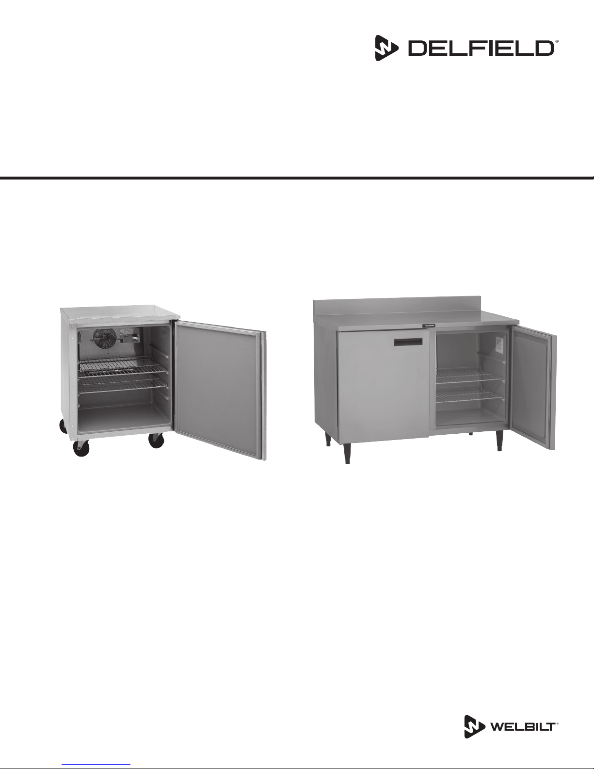
Compact Refrigerators & Freezers
400 & 4000 Series
Original Instructions
Installation, Operation and Maintenance Manual
This manual is updated as new information and models are released. Visit our website for the latest manual.
*9294045*
Part Number: 9294045 07/17
Page 2
Safety Notices
Warning
n
Read this manual thoroughly before operating, installing
or performing maintenance on the equipment. Failure
to follow instructions in this manual can cause property
damage, injury or death.
DANGER
Do not install or operate equipment that has been
misused, abused, neglected, damaged, or altered/
modified from that of original manufactured
specifications.
DANGER
Keep power cord AWAY from HEATED surfaces. DO NOT
immerse power cord or plug in water. DO NOT let power
cord hang over edge of table or counter.
DANGER
All utility connections and fixtures must be maintained
in accordance with Local and national codes.
Warning
n
Authorized Service Representatives are obligated to
follow industry standard safety procedures, including,
but not limited to, local/national regulations for
disconnection / lock out / tag out procedures for all
utilities including electric, gas, water and steam.
Warning
n
Do not store or use gasoline or other flammable vapors
or liquids in the vicinity of this or any other appliance.
Never use flammable oil soaked cloths or combustible
cleaning solutions, for cleaning.
Warning
n
Do not use electrical appliances or accessories other
than those supplied by the manufacturer.
Warning
n
Use caution when handling metal surface edges of all
equipment.
Warning
n
This appliance is not intended for use by persons
(including children) with reduced physical, sensory
or mental capabilities, or lack of experience and
knowledge, unless they have been given supervision
concerning use of the appliance by a person responsible
for their safety. Do not allow children to play with this
appliance.
Caution
,
Use caution handling, moving and use of the R290
refrigerators to avoid either damaging the refrigerant
tubing or increasing the risk of a leak. Components
shall be replaced with like components. Servicing shall
be done by a factory authorized service personnel to
minimize the risk of possible ignition due to incorrect
parts or improper service.
Notice
Proper installation, care and maintenance are
essential for maximum performance and trouble-free
operation of your equipment. Visit our website www.
mtwkitchencare.com for manual updates, translations,
or contact information for service agents in your area.
Warning
n
This product contains chemicals known to the State
of California to cause cancer and/or birth defects or
other reproductive harm. Operation, installation, and
servicing of this product could expose you to airborne
particles of glasswool or ceramic fibers, crystalline
silica, and/or carbon monoxide. Inhalation of airborne
particles of glasswool or ceramic fibers is known to the
State of California to cause cancer. Inhalation of carbon
monoxide is known to the State of California to cause
birth defects or other reproductive harm.
Page 3

Section 1
General Information
Section 2
Installation
Section 3
Operation
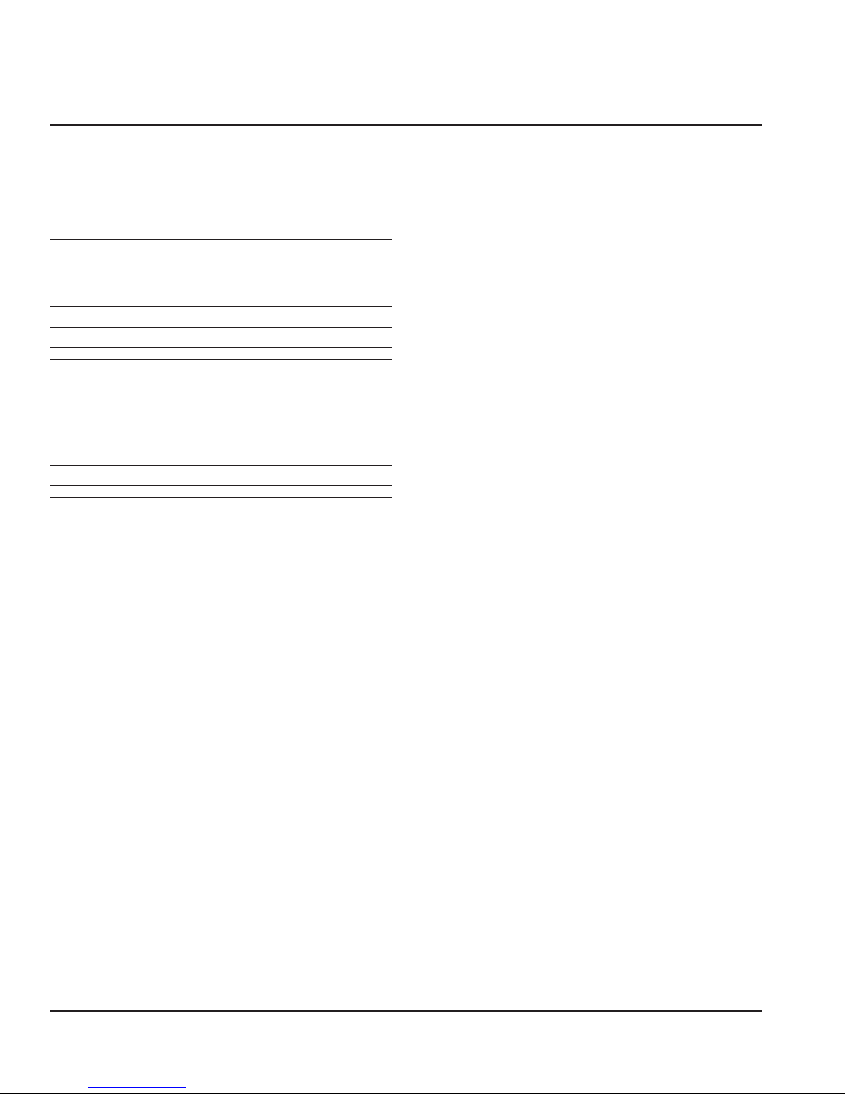
Table of Contents
Model Numbers .................................................................................................................. 4
Serial Number Location ..................................................................................................... 4
Warranty Information ........................................................................................................ 4
Regulatory Certifications ..................................................................................................4
Location ..............................................................................................................................5
Weight of Equipment .........................................................................................................6
Clearance Requirements ....................................................................................................6
Dimensions ......................................................................................................................... 6
Electrical Service ................................................................................................................ 7
Voltage .......................................................................................................................................................7
Ground Fault Circuit Interrupter .......................................................................................................7
Rated Amperages, Horsepower, Voltage & Power Cord Chart ...............................................7
Refrigeration ......................................................................................................................7
Drain Connections ..............................................................................................................7
Caster Or Leg Installation .................................................................................................. 8
Leg Leveling .............................................................................................................................................8
Caster and Leg Mounting Detail .......................................................................................................9
Loosen Freezer Compressor Bolts ..................................................................................... 9
Section 4
Maintenance
Section 5
Troubleshooting
Controls/Programming/Settings ....................................................................................11
R404A Refrigerators ............................................................................................................................ 11
R290 Refrigerators ............................................................................................................................... 11
Freezers ................................................................................................................................................... 12
Evaporator Fan Operation ................................................................................................................ 12
Interior Cleaning ..............................................................................................................14
Preventing Blower Coil Corrosion ................................................................................................. 14
Exterior Cleaning..............................................................................................................14
Drain ......................................................................................................................................................... 14
Cleaning the Condenser Coil ...........................................................................................14
Doors/Hinges .................................................................................................................... 14
Problem -> Cause -> Correction Chart ............................................................................15
Part Number: 9294045 07/17 3
Page 4
Section 1
General Information
Model Numbers
This manual covers standard units only.
NOTE: For custom units, consult Manitowoc KitchenCare at
1-844-724-CARE.
Work Top Refrigerator Bases With Stainless Steel Top &
Backsplash
402P ST4048P
Undercounter Refrigerator Bases With Stainless Steel Top
406P UC4048P
Undercounter Refrigerator With Subtop And 3.75” Casters
406CAP
The prefix P on a model number indicates the use of the
refrigerant propane.
Undercounter Freezer Base With Stainless Steel Top
407
Undercounter Freezer With Subtop And 3.75” Casters
407CA
Serial Number Location
The serial number on 400 series compact refrigerators and
freezers is printed on the right side of the interior back wall.
The serial tag on 4000 series compact refrigerators and
freezers is located either on the left upper sidewall inside
the cabinet or under the top nosing directly above the door
when the door is in the closed position (right hand door
when there are two doors).
Always have the serial number of your unit available
when calling for parts or service.
Warranty Information
Visit
http://www.delfield.com/warranty to:
• Register your product for warranty.
• Verify warranty information.
• View and download a copy of your warranty.
Regulatory Certifications
Models are certified by:
• National Sanitation Foundation (NSF)
• Underwriters Laboratories (UL)
• Underwriters Laboratories of Canada (cUL)
4 Part Number: 9294045 07/17
Page 5

Section 2
Installation
DANGER
Installation must comply with all applicable fire and
health codes in your jurisdiction.
Caution
,
Do not position the air intake vent near steam or heat
exhaust of another appliance.
DANGER
Use appropriate safety equipment during installation
and servicing
Warning
n
Remove all removable panels before lifting and
installing.
Warning
n
Do not damage the refrigeration circuit when installing,
maintaining or servicing the unit.
Location
Warning
n
This equipment must be positioned so that the plug is
accessible unless other means for disconnection from
the power supply (e.g., circuit breaker or disconnect
switch) is provided.
Warning
n
Adequate means must be provided to limit the
movement of this appliance without depending on or
transmitting stress to the electrical conduit or gas lines.
The location selected for the equipment must meet the
following criteria. If any of these criteria are not met, select
another location.
• Units are intended for indoor use only.
• The location MUST be level, stable and capable of
supporting the weight of the equipment.
• The location MUST be free from and clear of
combustible materials.
• Equipment MUST be level both front to back and side to
side.
• Position the equipment so it will not tip or slide.
• Front casters MUST be locked once positioned.
• Recommended air temperature is 41° - 86°F (5° - 30°C).
• Proper air supply for ventilation is REQUIRED AND
CRITICAL for safe and efficient operation. Refer to
Clearance Requirements chart on page 6.
• Do not obstruct the flow of ventilation air. Make sure the
air vents of the equipment are not blocked.
• Do not install the equipment directly over a drain.
Steam rising up out of the drain will adversely affect
operation, air circulation, and damage electrical /
electronic components.
Warning
n
To avoid instability the installation area must be capable
of supporting the combined weight of the equipment
and product. Additionally the equipment must be level
side to side and front to back.
Warning
n
This equipment is intended for indoor use only. Do not
install or operate this equipment in outdoor areas.
Part Number: 9294045 07/17 5
Page 6

Installation Section 2
Weight of Equipment
Model Weight
402P 176lbs (80kg)
406P 176lbs (80kg)
406CAP 168lbs (76kg)
407 176lbs (80kg)
407CA 168lbs (76kg)
ST4048P 234lbs (106kg)
UC4048P 236lbs (107kg)
Clearance Requirements
DANGER
Minimum clearance requirements are the same for
noncombustible locations as for combustible locations.
The flooring under the appliance must be made of a
noncombustible material.
DANGER
Risk of fire/shock. All minimum clearances must be
maintained. Do not obstruct vents or openings.
Dimensions
Model Length Depth Height
402P 27” (69cm) 28.5” (72cm) 39.5” (100cm)
406P 27” (69cm) 28.5” (72cm) 35.5” (90cm)
406CAP 27” (69cm) 27.75” (70cm) 33.25” (84cm)
407 27” (69cm) 28.5” (72cm) 35.5” (90cm)
407CA 27” (69cm) 27.75” (70cm) 33.25” (84cm)
ST4048P 48” (122cm) 28.5” (72cm) 39.5” (100cm)
UC4048P 48” (122cm) 28.5” (72cm) 35.5” (90cm)
Model Volume Shelf Space
402P
406P
406CAP
407
407CA
ST4048P
UC4048P
3
5.7Ft
(161L) 4.6Ft2 (43dm2)
3
10.80Ft
(306L) 8.0Ft2 (74dm2)
Back 3.00” (76mm)
Top / Sides 1.00” (25mm)
Bottom 2.00” (51mm)
• Keep the vents clean and free of obstruction.
• Legs or casters must be used and not removed.
6 Part Number: 9294045 07/17
Page 7

Section 2 Installation
Electrical Service
DANGER
Check all wiring connections, including factory
terminals, before operation. Connections can become
loose during shipment and installation.
DANGER
Units with two power cords must be plugged into
individual branch circuits. During movement, cleaning
or repair it is necessary to unplug both power cords.
Warning
n
This appliance must be grounded and all field wiring
must conform to all applicable local and national
codes. Refer to rating plate for proper voltage. It is the
responsibility of the end user to provide the disconnect
means to satisfy the authority having jurisdiction.
VOLTAGE
All electrical work, including wire routing and grounding,
must conform to local, state and national electrical codes.
The following precautions must be observed:
• The equipment must be grounded.
• A separate fuse/circuit breaker must be provided for
each unit.
• The maximum allowable voltage variation is ±10% of
the rated voltage at equipment start-up (when the
electrical load is highest).
• Check all green ground screws, cables and wire
connections to verify they are tight before start-up.
GROUND FAULT CIRCUIT INTERRUPTER
Ground Fault Circuit Interrupter (GFCI/GFI) protection is
a system that shuts down the electric circuit (opens it)
when it senses an unexpected loss of power, presumably
to ground. Welbilt does not recommend the use of GFCI/
GFI circuit protection to energize our equipment. If code
requires the use of a GFCI/GFI then you must follow the
local code. The circuit must be dedicated, sized properly
and there must be a panel GFCI/GFI breaker. We do not
recommend the use of GFCI/GFI outlets to energize our
equipment as they are known for more intermittent
nuisance trips than panel breakers.
RATED AMPERAGES, HORSEPOWER, VOLTAGE &
POWER CORD CHART
Units with plugs are supplied with approximately 6ft
(183cm) cords.
Models 406 and 407 may be stacked using a stacking collar.
In this case two 6ft (183cm) long grounded supply cords
and plugs are standard.
Model Amps HP Voltage,
Cycle, Phase
402P 4.0
406P 4.0
406CAP 4.0
407 5.8
407CA 5.8
ST4048P 4.0
UC4048P 4.0 1/5
1/5
115/60/1 5-15P
NEMA
Plug
Refrigeration
Model BTU/Hour
Capacity
402P 1356 210 100g R290
406P 1356 210 100g R290
406CAP 1356 210 100g R290
407 800 339 6.5oz R404A
407CA 800 339 6.5oz R404A
ST4048P 1356 316 100g R290
UC4048P 1356 316 100g R290
Heat of
Rejection
Refg Charge
Drain Connections
Warning
n
If a refrigerated base does not have a condensate
evaporator supplied, you must connect the condensate
line to a suitable drain. Otherwise, water will collect on
the floor, causing a potentially hazardous situation.
Warning
n
Moisture collecting from improper drainage can create a
slippery surface on the floor and a hazard to employees.
It is the owner’s responsibility to provide a container or
outlet for drainage.
Part Number: 9294045 07/17 7
Page 8

Installation Section 2
Caster Or Leg Installation
DANGER
Legs or casters must be installed and the legs or casters
must be screwed in completely to prevent bending.
When casters are installed the mass of this unit will
allow it to move uncontrolled on an inclined surface.
These units must be tethered/secured to comply with
all applicable codes.
Warning
n
The unit must be installed in a stable condition with
the front wheels locked. Locking the front casters after
installation is the owner’s and operator’s responsibility.
Warning
n
Use a jack to lift the refrigeration unit off the ground
just far enough to remove the leg/caster. Place blocking
underneath the unit. Do not work underneath a raised
unit without proper blocking. Do not lift the unit more
than necessary to remove the leg/caster. Lifting the unit
too far can make the unit unstable.
Caution
,
All single-section units require that the sw ivel casters
be mounted on the front and rigid casters be mounted
on the rear.
Caution
,
After installing casters, the unit must stand upright for
twenty-four (24) hours before being powered up to
assure oil return to the compressor sump.
Plate Casters
With Locks
Plate Casters
Without Locks
Screws
LEG LEVELING
All four legs are adjustable. Adjust each leg until the unit is
stable and level left to right. If necessary adjusting the front
legs slightly higher than the rear by about 1/8” (3mm) will
help the door remain closed.
1. Carefully place the unit on its back.
2. Located at each caster mounting location are 4 Phillips
head screws, for a total of 16 screws. Remove them.
3. Place a locking plate caster or leg over one of the front
holes, matching the 4 mounting holes to the pre-drilled
holes in the underside of the unit. Insert 4 Phillips head
screws and tighten. Repeat with the other locking front
caster or leg.
4. Repeat step 3 with the non-locking casters or legs in
the rear of the unit.
5. Carefully lift the unit upright.
8 Part Number: 9294045 07/17
Page 9

Section 2 Installation
2.38”
(60mm)
3.40”
(86mm)
2.38”
(60mm)
3.40”
(86mm)
2.82”
(72mm)
1.75”
(44mm)
CASTER AND LEG MOUNTING DETAIL
A universal bolt hole pattern is provided on the bottom of
the cabinet. It will accommodate any leg or caster. Simply
line up the plate holes with the corresponding cabinet
holes.
2.38”
(60mm)
3.40”
(86mm)
NOTE: If hole pattern on caster/leg matches the one above
mount in outer set of holes.
• 6” Leg - 3234569
1.75”
(44mm)
0.94”
(24mm)
2.14”
(54mm)
NOTE: If hole pattern on caster/leg matches the one above
mount in inner set of holes.
• 2” Caster - 3234148
Loosen Freezer Compressor Bolts
Semi hermetic models should be loosened before
operating. Loosen (but do not remove) the bolts on the
compressor. If not done the freezer may vibrate excessively
when the compressor is running,
2.82”
(72mm)
NOTE: If hole pattern on caster/leg matches the one above
mount in middle set of holes.
• 3” Caster - 3234024
• 5” Caster - 3234161
• 6” Leg - 3234791
Part Number: 9294045 07/17 9
Page 10

Section 3
Operation
DANGER
The on-site supervisor is responsible for ensuring that
operators are made aware of the inherent dangers of
operating this equipment.
DANGER
Do not operate any appliance with a damaged cord
or plug. All repairs must be performed by a qualified
service company.
DANGER
Never stand on the unit! They are not designed to
hold the weight of an adult, and may collapse or tip if
misused in this manner.
Warning
n
Do not contact moving parts.
Warning
n
All covers and access panels must be in place and
properly secured, before operating this equipment.
Warning
n
Do not use electrical appliances inside the food storage
compartment of this appliance.
Warning
n
The operator of this equipment is solely responsible
for ensuring safe holding temperature levels for all
food items. Failure to do so could result in unsafe food
products for customers.
Warning
n
Overloading shelves can damage equipment or cause
bodily injury.
Warning
n
Damp or wet hands may stick to cold surfaces.
Warning
n
Do not block the supply and return air grills or the air
space around the air grills. Keep plastic wrappings,
paper, labels, etc. from being airborne and lodging in
the grills. Failure to keep the air grills clear will result in
unsatisfactory operation of the system.
Caution
,
Do not throw items into the storage area. Failure to
heed this recommendation could result in damage to
the interior of the cabinet or to the blower coil.
10 Part Number: 9294045 07/17
Page 11

Section 3 Operation
Controls/Programming/Settings
R404A REFRIGERATORS
After the unit is connected to power it will automatically
begin operating. With the doors closed, the temperature
of the cabinet should reach 36°F to 40°F (2°C to 4°C) on
refrigerators in about one hour.
A thermostat located in the evaporator housing on interior
rear of the unit, controls the temperature in the box. The
factory setting for the control is 4 and maintains about 38°F
(3°C) in the box. Set toward 1 for higher temperatures and
toward 7 for lower temperatures.
Refrigerators defrost automatically with every cycle of the
compressor. The water generated is routed to a pan on the
rear of the unit and is evaporated by the heat given off by
the compressor.
During normal operation the evaporator fan may cycle
and/or pulse independently of the compressor. Consult
the service manual or contact Technical Support at
1-844-724-CARE if you are unsure of the proper
function.
R290 REFRIGERATORS
At initial start-up or anytime power is disconnected, then
reconnected to the unit, the control will delay all operations
for a short time (up to 30 minutes.) While in this delay
period the control will initialize.
With the doors closed, the temperature of the cabinet
should reach 36°F to 40°F (2°C to 4°C) on refrigerators
in about one hour. The electronic temperature control
constantly monitors box temperature and evaporator coil
temperature to maintain consistent product temperatures.
Refrigerators periodically go into defrost to allow
the accumulated frost on the evaporator to clear, the
compressor and condenser fan motor will turn off when
the temperature control detects a certain evaporator
temperature. After the defrost cycle is complete, the
temperature control will return to a normal cooling cycle.
The water generated is routed to a pan on the rear of
the unit and is evaporated by the heat given off by the
compressor.
During normal operation the evaporator fan may cycle
and/or pulse independently of the compressor. Consult
the service manual or contact Technical Support at
1-844-724-CARE if you are unsure of the proper
function.
Electronic Temperature Control Location & Adjustment
Part Number: 9294045 07/17 11
Rear View Of R290 Refrigerator
The control is located in the control box at the rear of
the unit. Never turn the knob more than one dial
number and always allow eight hours for temperature
stabilization before making any additional adjustments.
To adjust for colder temperatures, turn the knob clockwise.
For warmer temperatures, turn the knob counterclockwise. Turn the knob fully counter-clockwise to turn the
refrigeration system off.
Page 12

Operation Section 3
FREEZERS
This unit does not have a power switch, plug the unit in
to begin operation. At initial start-up or anytime power is
disconnected, then reconnected to the unit, the control
will delay all operations for a short time (up to 40 minutes).
While in this delay period, the control initializes the control
parameters and confirms that the temperature sensors and
circuits are operational.
After initializing, the control will immediately enter a
DEFROST mode. The compressor and condenser fan as well
as the evaporator fan will remain off until initial defrost
is complete. This initial defrost cycle may take up to 15
minutes to complete, then the freezing cycle will begin.
After initializing and the defrost cycle, the electronic
temperature control will cycle the compressor, evaporator
fan motor, and condenser fan motor to maintain box
temperature at the control setting.
With the doors closed, the temperature of the cabinet
should reach 0°F (-18°C) on freezers in about one hour
after the freezing cycle begins. The electronic temperature
control constantly monitors box temperature as well as
evaporator coil temperature to maintain consistent product
temperatures. As an added energy-saving feature, the
electronic controller will switch the evaporator fan motor
on and off with the compressor and condenser fan motor.
During normal operation the evaporator fan may cycle
and/or pulse independently of the compressor. Consult
the service manual or contact Technical Support at
1-844-724-CARE if you are unsure of the proper
function.
Electronic Temperature Control Location & Adjustment
Never turn the knob more than one dial number and
always allow eight hours for temperature stabilization
before making any additional adjustments. The control
is located in the control box at the rear of the unit. It is
factory set at mid-range to maintain about -3°F (-18°C) box
temperature. To adjust for colder temperatures, turn the
knob clockwise. For warmer temperatures, turn the knob
counter-clockwise. Turn the knob fully counter-clockwise to
turn the refrigeration system off.
Freezer Automatic Defrost
The control also monitors compressor total running time
and will enter a defrost cycle after total compressor running
time is greater than five hours since the last defrost cycle
OR if evaporator coil temperature drops below -34°F (-37°C)
(indicating excessive frost on the coil).
Freezer Manual Defrost
If a manual defrost is desired, simply unplug the unit for
several seconds, then plug unit back in. This will cause the
control to re-initialize and then enter a defrost cycle.
When the control enters the defrost mode, whether manual
or automatic, it switches off the evaporator fan motor,
compressor and condenser fan motor, and switches on the
defrost heater to warm the evaporator coil and melt all frost
accumulated during the previous refrigeration cycle. The
control will continue the defrost cycle for a MINIMUM of
eight minutes and a MAXIMUM of 30 minutes depending
on the amount of frost accumulated on the evaporator coil.
After the defrost cycle is complete, the control returns
to a normal refrigeration cycle, however the evaporator
fan motor will not switch on for two minutes AFTER
the compressor and condenser fan motor have begun
operating.
EVAPORATOR FAN OPERATION
Cooling Cycle Defrost Cycle
Compressor OnCompressor
Off
Evap Fan Evap Fan Evap Fan
R404A
Refrigerators
R290
Refrigerators
Freezer On Off Off
On On On
On Cycles
On 3-Min
Off 3Min
Compressor
Off
On
12 Part Number: 9294045 07/17
Page 13

Section 4
Maintenance
DANGER
It is the responsibility of the equipment owner to
perform a Personal Protective Equipment Hazard
Assessment to ensure adequate protection during
maintenance procedures.
DANGER
Failure to disconnect the power at the main power
supply disconnect could result in serious injury or death.
The power switch DOES NOT disconnect all incoming
power.
DANGER
Disconnect electric power at the main power disconnect
for all equipment being serviced. Observe correct
polarity of incoming line voltage. Incorrect polarity can
lead to erratic operation.
Warning
n
Never use sharp objects or tools to remove ice or frost.
Do not use mechanical devices or other means to
accelerate the defrosting process.
Warning
n
When cleaning interior and exterior of unit, care should
be taken to avoid the front power switch and the rear
power cord. Keep water and/or cleaning solutions away
from these parts.
Warning
n
Never use a high-pressure water jet for cleaning or hose
down or flood interior or exterior of units with water. Do
not use power cleaning equipment, steel wool, scrapers
or wire brushes on stainless steel or painted surfaces.
Caution
,
Maintenance and servicing work other than cleaning as
described in this manual must be done by an authorized
service personnel.
Caution
,
Over shelves and other items mounted to the top of the
counters should never be installed in the field due to
the potential damage to the refrigeration system.
Warning
n
When using cleaning fluids or chemicals, rubber gloves
and eye protection (and/or face shield) must be worn.
Maintenance Daily Weekly Monthly
Interior X X X
Gasket X X X X
Exterior X X X
Drain X X X
Condenser Coil X X X
Casters X X X
Responsibility
You are responsible for maintaining the equipment
in accordance with the instructions in this manual.
Maintenance procedures are not covered by the warranty.
After Prolonged
Shutdown
At Start-Up
Part Number: 9294045 07/17 13
Page 14

Maintenance Section 4
Interior Cleaning
The interior can be cleaned using soap and warm water. If
this isn’t sufficient, try ammonia and water or a nonabrasive
liquid cleaner.
PREVENTING BLOWER COIL CORROSION
To help prevent corrosion of the blower coil, store all acidic
items, such as pickles and tomatoes, in seal-able containers.
Immediately wipe up all spills.
Exterior Cleaning
Caution
,
Never use an acid based cleaning solution on exterior
panels! Many food products have an acidic content,
which can deteriorate the finish. Be sure to clean the
stainless steel surfaces of ALL food products.
Clean the area around the unit as often as necessary to
maintain cleanliness and efficient operation.
Wipe gasket and surfaces with a damp cloth rinsed in water
to remove dust and dirt from the outside of the unit. Always
rub with the “grain” of the stainless steel to avoid marring
the finish. If a greasy residue persists, use a damp cloth
rinsed in a mild dish soap and water solution. Wipe dry with
a clean, soft cloth.
Never use steel wool or abrasive pads for cleaning. Never
use chlorinated, citrus based or abrasive cleaners.
Stainless steel exterior panels have a clear coating that
is stain resistant and easy to clean. Products containing
abrasives will damage the coating and scratch the panels.
Daily cleaning may be followed by an application of
stainless steel cleaner which will eliminate water spotting
and fingerprints. Early signs of stainless steel breakdown
are small pits and cracks. If this has begun, clean thoroughly
and start to apply stainless steel cleaners in attempt to
restore the steel.
Wipe casters with a damp cloth monthly to prevent
corrosion.
DRAIN
Each unit has a drain located inside the unit that removes
the condensation from the evaporator coil and routes it
to an external condensate evaporator pan. Each drain can
become loose or disconnected during normal use. If you
notice water accumulation on the inside of the unit, be sure
the drain tube is connected to the evaporator drain pan.
If water is collecting underneath the unit, make sure the
end of the drain tube is in the condensate evaporator. The
leveling of the unit is important as the units are designed to
drain properly when level. Be sure all drain lines are free of
obstructions.
Cleaning the Condenser Coil
In order to maintain proper refrigeration performance, the
condenser fins must be cleaned of dust, dirt and grease
regularly. It is recommended that this be done monthly. If
conditions are such that the condenser is totally blocked
in a month, the frequency of cleaning should be increased.
Clean the condenser with a vacuum cleaner or stiff brush. If
extremely dirty, a commercially available condenser cleaner
may be required.
Failure to maintain a clean condenser coil can initially cause
high temperatures and excessive run times. Continuous
operation with a dirty or clogged condenser coil can
result in compressor failure. Neglecting the condenser coil
cleaning procedures will void any warranties associated
with the compressor and cost to replace the compressor.
Doors/Hinges
Over time and with heavy-use doors, the hinges may
become loose. If this happens, tighten the screws that
mount the hinge brackets to the frame of the unit. Loose
or sagging doors can cause the hinges to pull out of the
frame, which may damage both the doors and the hinges.
In some cases this may require qualified service agents or
maintenance personnel to perform repairs.
Door Adjustment
If the door needs lowering at the handle, use a 5/16” (8mm)
wrench to loosen the hinge screws and install a spacer
outside of the hinge. Tighten the screws.
If the door needs to be higher at the handle, use a 5/16”
(8mm) wrench to loosen the hinge screws and install a
spacer inside of the hinge. Tighten the screws.
14 Part Number: 9294045 07/17
Page 15

Section 5
Troubleshooting
Problem -> Cause -> Correction Chart
Problem Cause Correction
Cabinet not
running
Condensing
unit runs for
long periods or
continuously
Cabinet
temperature is too
high
Cabinet is noisy Loose part(s). Locate and tighten loose part(s).
Fuse blown or circuit breaker tripped. Replace fuse or reset circuit breaker.
Power cord unplugged. Plug in power cord.
Thermostat set too high. Set thermostat to lower temperature.
Main power switch turned off. Turn main power switch on.
Cabinet in defrost cycle.
(Freezer models)
Excessive amount of warm product placed in
cabinet.
Prolonged door openings or door(s) ajar. Make sure door(s) are closed when not in use. Avoid
Door gasket(s) not sealing properly. Check gasket condition. Adjust door or replace gasket if
Dirty condenser coil. Clean the condenser coil.
Evaporator coil iced over. Turn unit off and allow coil to defrost.
Thermostat set too high. Set thermostat to lower temperature.
Poor air circulation in cabinet. Re-arrange product to allow proper air circulation.
Exterior thermometer is out of calibration. Re-calibrate thermometer.
Excessive amount of warm product placed in
cabinet.
Prolonged door openings or door(s) ajar. Make sure door(s) are closed when not in use.
Dirty condenser coil. Clean the condenser coil.
Evaporator coil iced over. Turn unit off and allow coil to defrost.
Allow adequate time for product to cool down.
Allow adequate time for product to cool down.
Wait for defrost cycle to finish.
prolonged door openings.
necessary.
Make sure thermostat is not set too cold.
Also, check gasket condition.
Avoid prolonged door openings.
Make sure thermostat is not set too cold.
Also, check gasket condition.
Refrigerator is
freezing product
Compressor will
not start
Thermostat is set too low. Set thermostat to higher temperature.
Dirty condenser coil. Clean the condenser coil.
Not enough cabinet clearance for proper
refrigeration system operation.
Low voltage to cabinet. Check and correct incoming voltage to cabinet.
Part Number: 9294045 07/17 15
Move cabinet or make other adjustments to gain proper
cabinet clearances.
Page 16

DELFIELD
980 SOUTH ISABELLA ROAD, MOUNT PLEASANT, MI 48858
800-733-8821
WWW.DELFIELD.COM
Welbilt provides the world’s top chefs, and premier chain operators or growing independents with industry leading equipment and solutions.
Our cutting-edge designs and lean manufacturing tactics are powered by deep knowledge, operator insights, and culinary expertise.
All of our products are backed by KitchenCare® – our aftermarket, repair, and parts service.
CLEVELAND
CONVOTHERM®
©2017 Welbilt Inc. except where explicitly stated otherwise. All rights reserved. Continuing product improvement may necessitate change of specications without notice.
Part Number: 9294045 07/17
DELFIELD®
FITKITCHEN™
FRYMASTER®
GARLAND
KOLPAK®
LINCOLN
WWW.WELBILT.COM
MANITOWOC®
MERCO®
MERRYCHEF®
MULTIPLEX®
 Loading...