

Welbilt ArcticFox Installation & Operation Manual

550005898-2
Kolpak
ArcticFox WiFi Controller
With Tru-Dmnd™ Defrost
Installation & Operation
Manual
www.welbilt.com 800-225-9916 1
Welbilt
2915 Tennessee Avenue North
Parsons, TN 38363
Phone: 800-225-9916
www.welbilt.com
August 2018

Table of Contents
General Safety Information ........................................................................................................ 3
Receiving Inspection ................................................................................................................... 4
Locating and Mounting Condensing Units ...............................................................................4-5
Locating and Mounting Evaporator Coils .................................................................................6-7
Wiring ......................................................................................................................................... 7
Piping ..................................................................................................................................... 8-13
Leak Test ............................................................................................................................. 14-15
Evacuation ........................................................................................................................... 15-16
Refrigerant Charg ing ................................................................................................................. 17
Suction/Liquid Line Sizing Chart ............................................................................................... 18
Operational Start-Up ................................................................................................................ 19
Navigation Using The Basic Display .......................................................................................... 19
Introduction To ArcticFox Smart Access............................................................................... 20-26
Setting Up Email/Text Alerts ..................................................................................................... 27
Maintenance ....................................................................................................................... 28-29
Evaporator Troubleshooting ...................................................................................................... 29
Condensing Unit Troubleshooting ........................................................................................ 30-31
System Start-Up Data Sheet ................................................................................................ 32-35
Warranty Information................................................................................................................. 36
www.welbilt.com 800-225-9916 2
WARNING
Warning statement before proceeding and work carefully.
AVERTISSEMENT
CAUTION
carefully.
MISE EN GARDE
travailler prudemment.
General Safety Information
Read this manual carefully before beginning the installation and operation of the
refrigeration system. Special attention is required to all sections identified with the
following warning and caution notices provided in both English and French languages:
Text in a Warning box alerts you to a potential personal injury situation. Read each
Le texte qui figure dans les encadrés d’avertissement vous alerte d’une
situation pouvant potentiellement causer des blessures. Lire chaque
déclaration d’avertissement avant de procéder et travailler prudemment.
Text in a Caution box alerts you to a situation in which you could damage the
refrigeration system. Read each Caution statement before proceeding and work
Le texte qui figure dans les encadrés de mise en garde vous alerte d’une
situation dans laquelle le système de réfrigération pourrait subir des
dommages. Lire chaque déclaration de mise en garde avant de procéder et
Disregarding these special notices may result in personal injury and/or damage to the
refrigeration system.
Safety Notices:
Installation and mainte nance/servicing are to be performed only by trained and
qualified personnel familiar with commercial refrigerati on sy st ems.
Ensure that all field wiring conforms to the equipment requirements and all
applicable local and national codes.
Disconnect all power sources before servicing the refrigeration equi pme nt.
Sheet metal and coil surfaces have sharp edges. Use appropriate protective
gloves to prevent injury.
Use appropriate eye protection during installation and servicing.
www.welbilt.com 800-225-9916 3
WARNING
occur!
AVERTISSEMENT
Receiving Inspection
Check the shipment carefully and compare to the bill of lading. Account for all items
listed and inspect each container for damage. Carefully inspect for any concealed
damage. Report any shortages or damages to the carrier, note on the bill of lading, and
file a freight claim.
Damaged material cannot be returned to the manufacturer without prior approval. A
Return Material Authorization (RMA) must be obtained. Contact a sales representative
at 800-826-7036.
Locating and Mounting Condensing Unit
General Guidelines:
Check the selected installation location to ensure that racks, braces, flooring,
foundations, etc. are adequate to support the condensing unit weight.
The installation location is clean, dry, and level.
Locate away from corrosive and noise sensitive atmospheres.
Use the condensing unit skid and base when moving the unit. Do not remove
unit from skid until the unit is moved to the mounting location.
Mount the condensing unit base to pads or structural rails using properly sized
bolts through the unit base. Ce nter o f cond en s i ng unit needs to be properly
supported.
Do not lift the condensing unit by the refrigerant tubing or components. These
features will not support the condensing unit weight. Injury and unit damage may
Ne pas soulever le groupe compresseur-condenseur par les tubes ou les
composants du réfrigérant. Ces éléments ne supporteront pas le poids du
groupe compresseur-condenseur. Cela pourrait entraîner des blessures et
des dommages à l’appareil!
www.welbilt.com 800-225-9916 4
CAUTION
performance and prematur e eq ui pm ent fai l ur e !
MISE EN GARDE
BUILDING WALL
(VIEWED FROM ABOVE)
AIR
AIR
MINIMUM
INTAKE AIR
MINIMUM DISTANCE 24”
24”
INTAKE AIR
MINIMUM DISTANCE 24”
24”
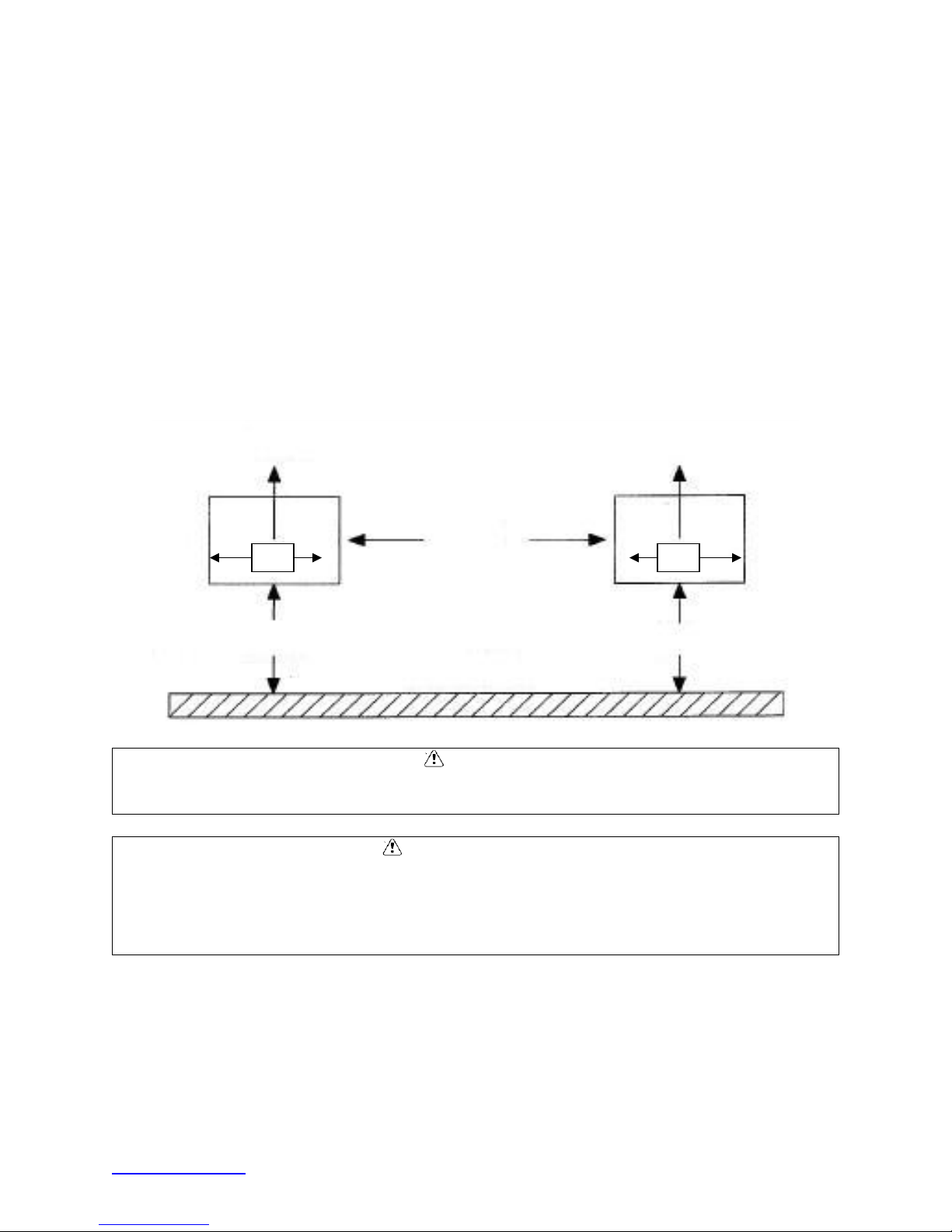
Clearance Requirements:
Locate where there is a sufficient and unrestricted supply of clean ambient air.
Locate where this is adequate space for the removal of the heated discharged air
from the condensing unit area.
Do not position multiple units so that discharge air from one unit is blowing into
the condenser inlet air of the other unit.
All sides of the unit should be positioned a minimum distance equal to the total
width of the condensing unit away from any other unit, wall, or obstruction.
Example of Multiple Units with Horizontal Airflow
FLOW
DISTANCE
24”
FLOW
Failure to observe clearance and air flow requirements will result in poor system
Le non-respect des exigences de dégagement et de circulation d’air aura
pour résultat un rendement médiocre du système et une défaillance
prématurée de l’équipement!
www.welbilt.com 800-225-9916 5
CAUTION
performance and prematur e eq ui pm ent fai l ur e !
MISE EN GARDE
Locating and Mounting Evaporator Coil
General Guidelines:
Do not place the evaporator above or close to door openings. This will help
prevent potential icing problems.
Allow a minimum clearance equal to or greater than the coil height on all sides of
the coil for proper air flow and service access.
Use the evaporator coil for a template to locate and drill the mounting holes (1/2”
diameter).
Place a 1” and a 1-5/8” washer on each nylon bolt and insert through the drilled
mounting holes in the ceiling from the exterior of the walk-in ceiling panel.
NOTE: Nylon bolts are supplied to prevent thermal transfer between the exterior
of the walk-in and the interior of the walk-in. Do not use metal bolts.
Lift the evaporator coil until the nylon bolts extend through the mounting
brackets.
Install washers and secure with nuts. Tighten until the coil is firm against the
ceiling. The evaporator coil must be level.
Additional information is available in the installation manual supplied with the
evaporator.
Failure to observe clearance and air flow requirements will result in poor system
Le non-respect des exigences de dégagement et de circulation d’air aura
pour résultat un rendement médiocre du système et une défaillance
prématurée de l’équipement!
www.welbilt.com 800-225-9916 6

Evaporator Coil Mounting Diagram
Wiring
All electrical connections and routing must comply with local and national codes. Do not
modify the factory installed wiring without written factory approval. The field wiring must
enter through the knockouts provided. Refer to the nameplate on the condensing or
evaporator coil to determine the proper electrical power supply. Wire type should be of
copper conductor only and properly sized to handle the electrical load. The unit and coil
must be properly grounded. Condensing unit wiring diagrams are located inside this
installation manual and attached inside the electrical box cover. Evaporator coil wiring
diagrams are located inside this installation manual and inside the evaporator cov er .
NOTE: CAT-5 cables, which are included, need to be routed from the evaporators
to the network router for access to the internet. Please contact the end user for
proper connection point.
www.welbilt.com 800-225-9916 7
WARNING
may result in injury!
AVERTISSEMENT
CAUTION
Connections can become loose during shipment and installation.
MISE EN GARDE
All wiring must comply with local and national codes. Wiring must be performed only
by a refrigeration technician or certified electrician. Failure to follow these guidelines
Tout le câblage doit être conforme aux codes locaux et nationaux. Le
câblage ne doit être effectué que par un technicien en réfrigération ou un
électricien agréé. Le non-respect de ces consignes peut entraîner des
blessures!
Check all wiring connections, including factory terminals, before operation.
Vérifier toutes les connexions de câblage, y compris les bornes installées
en usine, avant de faire fonctionner l’appareil. Les connexions peuvent
devenir lâches pendant l’expédition et l’installation.
Piping
General Requirements:
All refrigeration piping and components are to be installed in accordance with applicable
local and national codes and in conformance with industry refrigeration guidelines to
ensure proper operation of the refrigeration system. Only refrigeration grade copper
tubing should be used. Long radius elbows should be used. Short radius elbows have
points of excessive stress concentration and are subject to breaking at these points, do
not use short radius elbows. Suction lines must be insulated with a minimum ¾” thick
insulation tubing to reduce heat pick-up.
www.welbilt.com 800-225-9916 8
CAUTION
can result in premature system failure.
MISE EN GARDE
CAUTION
premature system fail ur e.
MISE EN GARDE
Cleanliness:
Condensing units and evaporator coils are cleaned and dehydrated at the factory. The
condensing unit must remain closed and pressurized until the piping is complete and
final connections are r eady to be made.
The maximum air exposure for dehydrated condensing units is 15 minutes. Systems
exposed longer than 15 minutes must have the compressor oil and drier filter
replaced. Leaving a system exposed to the atmosphere for more than 15 minutes
L’exposition maximale à l’air des groupes compresseurs-condenseurs
déshydratés es t de 15 minutes. L’huile du compresseur et le filtre du
dessiccateur doivent être remplacés sur les systèmes qui ont été exposés à
l’air pendant plus de 15 minutes. L’exposition d’un système à l’atmosphère
pendant plus de 15 minutes peut avoir pour résultat une défaillance
prématurée du système.
Do not remove base mount valve covers until work is ready to be performed. Ensure
that all refrigeration tubing is clean and dry prior to installation. Use only tubing cutters
when trimming tubing to the proper length. Do not use saws to cut tubing.
The use of saws to cut tubing can contaminate the system with copper chips causing
L’utilisation de scies pour couper le tubage peut contaminer le système par
des copeaux de cuivre et causer une défaillance prématurée du système.
www.welbilt.com 800-225-9916 9
CAUTION
failure.
MISE EN GARDE
CAUTION
resulting in premature c ompressor failure.
MISE EN GARDE
Brazing joints require a dry inert gas, typically nitrogen, be passed through the lines at a
low pressure to prevent scaling and oxidation. Use only silver solder brazing alloys.
Minimize the amount of flux to prevent internal contamination. Flux only the male
portion of the joint. Thoroughly clean fluxed joints after brazing.
Dry inert gas must be passed through the system while brazing to prevent scaling and
oxidation. Scaling and oxides can clog refrigeration components resulting in system
Le gaz sec inerte doit passer par le système pendant le brasage afin de
prévenir l’entartrage et l’oxydation. Le tartre et les oxydes peuvent
bloquer les éléments de réfrigération et causer une défaillance du système.
Pipe Supports:
All tubing should be supported in at least two locations (near the end of each tubing
run). Long runs will require additional support. As a guide, support 3/8” to 7/8” pipe
every five feet, 1-1/8” to 1-3/8” every seven feet, and 1-5/8” to 2-1/8” every ten feet. Do
not leave a corner unsupported when changing directions. Place supports within 2 feet
of each direction change. Piping that is attached to a vibrating object (such as a
compressor or compressor base) must be supported in a manner that will not restrict
the movement of the vibrating object. Rigid mounting will fatigue the tubing causing
refrigerant leaks.
Oil Traps:
To ensure proper oil return to the compressor, a P-type oil trap should be installed at
the base of each suction riser of four feet or more. The suction trap must be the same
size as the suction line. Additional traps are necessary for long vertical risers. Add a
trap for each length of pipe (approximately 20 feet) to insure proper oil return. Suction
lines must slope ¼” per 10 feet toward the compressor. Install a suction line trap at the
evaporator outlet if the suction line rises to a point higher than the connection on the
evaporator.
Failure to properly install oil traps can prevent sufficient oil return to the compressor
L’installation incorrecte des siphons d’huile peut empêcher un retour
d’huile suffisant au compresseur, entraînant une défaillance prématurée du
compresseur.
www.welbilt.com 800-225-9916 10

www.welbilt.com 800-225-9916 11
WARNING
AVERTISSEMENT
Pressure Regulating-Relief Valves:
Do not defeat, cap, add piping to the outlet of the valve, or, attempt to
change the relief setting.
Ne pas annuler, mettre un capuchon, ajouter de la tuyauterie à la prise de
la valve ou tenter de modifier le réglage de décharge.
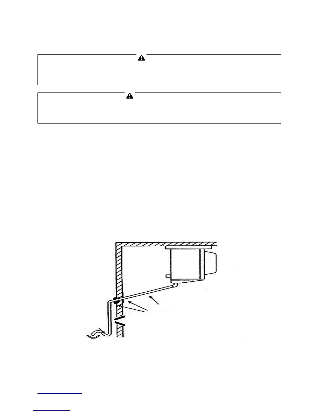
Drain Lines:
Evaporator coil drain lines shoul d be pi tched a minimum of 1/2” per foot to allow proper
drainage and exit the wal k-in as quickly as possible. Insulate and seal the drain line
where it passes through the wall. Copper drain line is required. Freezer compartment
drain lines must have heat tape wrapped around the copper drain line and must have
¾” thick insulation tubing. Do not locate drain line P-traps within the freezer space. Do
not reduce the drain line size. Locate a drain line P-trap outside o f the cooler space.
Any outdoor P-traps exposed to low ambient temperatures should be wrapped with a
drain line heater (provide 20 watts of heat per foot of drain line at 0°F, 30 watts per foot
at -20°F. Freezer/cooler combo boxes can have one common drain line. However,
there must be a P-trap located between the freezer evaporator and the cooler
evaporator located inside the cooler compartment. The cooler compartment P-trap
should be located between the cooler evaporator and the external drain location.
www.welbilt.com 800-225-9916 12
 Loading...