

Wel-Bilt 21306 Owner's Manual
SOLAR POWERED
AUTO-DARKENING WELDING HELMET
OWNER’S MANUAL
WARNING:
Read carefully and understand all ASSEMBLY AND OPERATION
INSTRUCTIONS before operating. Failure to follow the safety rules and other
basic safety precautions may result in serious personal injury.
Ite m # 21306
Page of 7
2
Thank you very much for choosing a WEL-BILT product! For future reference, please complete
the owner’s record below:
Model: _______________ Purchase Date: _______________
Save the receipt, warranty and these instructions. It is important that you read the entire manual
to become familiar with this product before you begin using it.
This helmet is designed for certain applications only. The distributor cannot be responsible for
issues arising from modification. We strongly recommend this machine not be modified and/or
used for any application other than that for which it was designed. If you have any questions
relative to a particular application, DO NOT use the machine until you have first contacted the
distributor to determine if it can or should be performed on the product.
For technical questions please call 1-800-222-5381.
INTENDED USE
The Solar-Powered Auto-Darkening Welding Helmet is ideal for most welding applications and
designed to meet the most demanding requirements. This helmet’s 1/10,000-second switch time
automatically darkens the lens the instant you start welding.
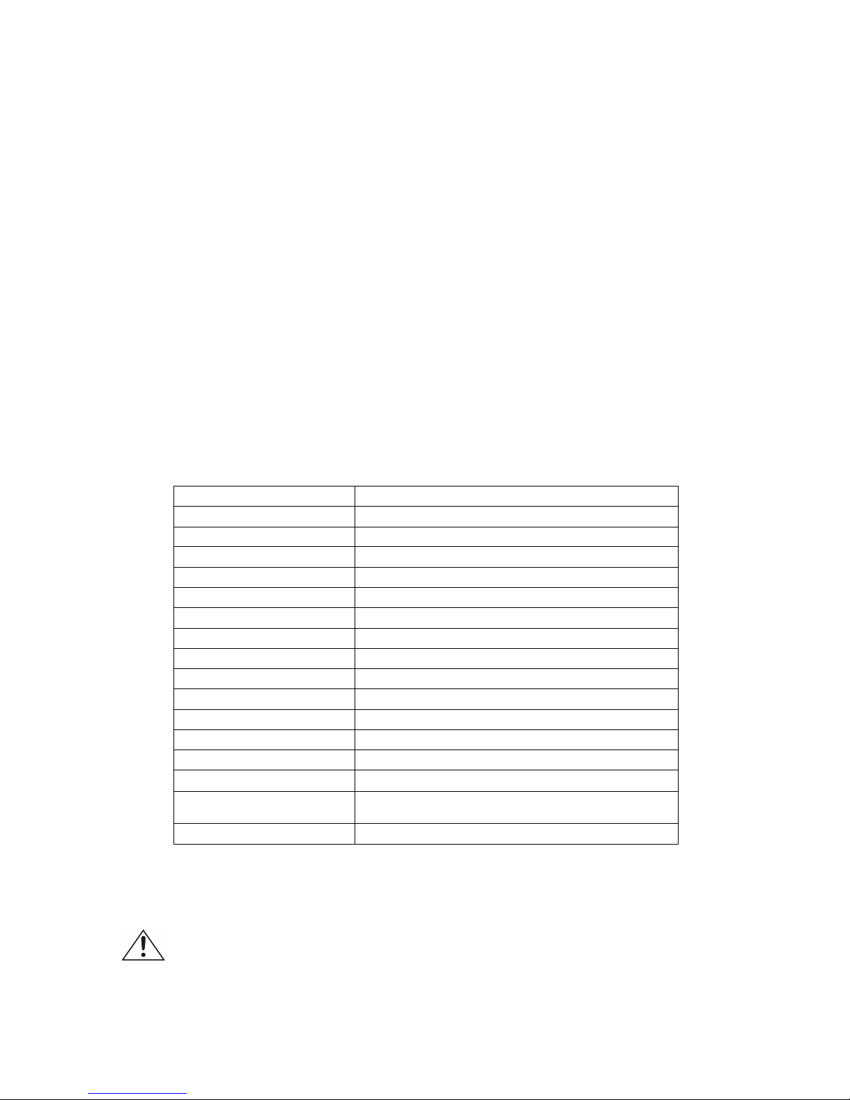
TECHNICAL SPECIFICATIONS
Viewing Area:
98 x 44mm (3.86" x 1.73")
Cartridge Size:
110 x 90 x 9mm (4.33" x 3.54" x 0.35")
Arc Sensor:
2
Light State:
DIN 3.5
Dark State:
DIN 9 ~ 13
Shade Control:
External, Variable Shade
Power On/Off:
Fully Automatic
UV/IR Protection:
Up to Shade DIN16 at all times
Power Supply:
Solar cell. No battery change required
Switching Time:
1/10,000 s. from Light to Dark
Low Amperage TIG Rated:
≥ 10 amps
Operating Temp.:
-10°C ~ +55°C (14°F ~ 131°F)
Storing Temp.:
-20°C ~ +70°C (- 4°F ~ 158°F)
Helmet Material:
High Impact Resistance Nylon
Total Weight:
435g (15.3oz.)
Application range:
MIG; MAG/CO2; SMAW; Air carbon cutting;
TIG ; PLASMA arc welding/cutting
Approved:
ANSI Z87.1, CSA Z94.3
GENERAL SAFETY RULES
WARNING: Read and understand all instructions. Failure to follow all instructions listed
below may result in serious injury.

Page of 7
3
CAUTION: Do not allow persons to operate or assemble this auto darkening welding
helmet until they have read this manual and have developed a thorough understanding of
how the welding helmet works.
WARNING: The warnings, cautions, and instructions discussed in this instruction
manual cannot cover all possible conditions or situations that could occur. It must be
understood by the operator that common sense and caution are factors that cannot be built into this
product, but must be supplied by the operator.
SAVE THESE INSTRUCTIONS
IMPORTANT SAFETY CONSIDERATIONS
• Should this helmet not darken upon striking an arc, stop welding immediately and contact your
supervisor or your dealer.
• Use only at temperatures: -10º C ~ +55º C (14°F ~ 131°F)
• Storage temperature: -20º C ~ +70º C (- 4°F ~ 158°F)
• Regularly replace the front cover lens if it becomes cracked/ scratched/pitted.
• The materials which may come into contact with the wearers skin, can cause allergic reactions in
some circumstances.
ADJUSTING THE FIT OF THE HELMET
The overall circumference of the headband can be made larger or smaller by rotating the knob on
the back of the headband. (See adjustment “Y” in fig.1). This can be done whilst wearing the helmet
and allows just the right tension to be set to keep the helmet firmly on the head without it being too
tight.
• If the headband is riding too high or too low on your head, adjust the strap which passes over the
top of your head. To do this release the end of the band by pushing the locking pip out of the hole in
the band. Slide the two portions of the band to a greater or lesser width as required and push the
locking pip through the nearest hole. (See adjustment “W” in fig.1).
• Test the fit of the headband by lifting up and closing down the helmet a few times while wearing it.
If the headband moves while tilting, re-adjust it until it is stable.
ADJUSTING THE DISTANCE BETWEEN THE HELMET AND THE FACE
Step 1: Undo the block nut (See “T” in fig. 1) to adjust the distance between the helmet and your
face in the down position.
Step 2: Loosen the block nut on either side of the helmet and slide it nearer or further from your face.
(See adjustment “Z” in fig.1). It is important that your eyes are each the same distance from the lens.
Otherwise the darkening effect may appear uneven.
Step 3: Re-tighten the block nut when adjustment is complete.
ADJUSTING VIEW ANGLE POSITION
Please see fig.2.
SELECTING SHADE LEVEL
Select the shade level you require according to the welding process you will use by referring to the
“Shade Guide Table” below for settings. Turn the shade control knob on the side of the helmet to the
shade number required.
You are now ready to use the helmet.
 Loading...