

Weil-McLain UO-3 CV, UO-3 DV, UO-4 DV, UO-4 CV, UO-5 DV Instruction Manual
...
Beckett Model NX Burners
Instruction Manual
Oil Fired Water Boiler
WARNING
Incorrect installation, adjustment, or misuse of this burner could result in death, severe personal
injury, or substantial property damage.
To the Homeowner or Equipment Owner:
Please read and carefully follow all instructions provided
in this manual regarding your responsibilities in caring for
your heating equipment.
Contact a professional, qualifi ed service agency for
installation, start-up or service work.
Save this manual for future reference.
Potential for Fire, Smoke and Asphyxiation Hazards
Weil-McLain Part No. 550-141-996/510
To the Professional, Qualifi ed Installer or Service
Agency:
Please read and carefully follow all instructions provided
in this manual before installing, starting, or servicing this
burner or heating system.
The Installation must be made in accordance with all
state and local codes having jurisdiction.

2
To the Owner:
Thank you for purchasing a Beckett
burner for use with your heating appliance.
Please pay attention to the Safety Warnings
contained within this instruction manual. Keep
this manual for your records and provide it
to your qualifi ed service agency for use in
professionally setting up and maintaining your
oil burner.
Contents
General Information ....................................................4
Hazard Defi nitions ........................................................................4
Remainder of manual to be used ONLY BY
▼
Weil-McLain Burner Specifi cations ........................... 5
NX Burner Specifi cations for Weil-McLain Ultra Oil Boilers ..........5
General Information ....................................................6
Notice Special Requirements ........................................................6
QUALIFIED SERVICE TECHNICIANS
▼
Your Beckett burner will provide years of
effi cient operation if it is professionally
installed and maintained by a qualifi ed service
technician. If at any time the burner does not
appear to be operating properly, immediately
contact your qualifi ed service agency for
consultation.
We recommend annual inspection/service
of your oil heating system by a qualifi ed
service agency.
Daily – Check the room in which your burner/
appliance is installed. Make sure:
Air ventilation openings are clean and
y
unobstructed
Nothing is blocking burner inlet air
y
openings
No combustible materials are stored near
y
the heating appliance
There are no signs of oil or water leaking
y
around the burner or appliance
Weekly
Check your oil tank level. Always keep
y
your oil tank full, especially during the
summer, in order to prevent condensation
of moisture on the inside surface of the
tank.
Inspect/Prepare Installation Site ................................6
Clearances to Burner and Appliance .............................................6
Inspect Chimney or Direct Vent System ........................................6
Combustion Air Supply Information ...............................................7
Safety Shutoff for Direct Vent System ...........................................8
Direct/Sidewall Venting Application ..............................................8
Mounting dimensions ....................................................................8
Installing the Oil Tank and Supply System ....................................9
Fuel Line Valves and Filter ...........................................................9
Fuel supply level with or above burner ..........................................9
Wiring Connections Diagram ..................................................... 10
Burner Control ...........................................................12
Sequence of Operation - GeniSys 7505 .................................... 12
Start the Burner and Set Combustion .....................15
Start-up and Initial Settings ........................................................ 15
Set Combustion with Test Instruments ....................................... 15
Cover Installation ....................................................................... 17
Trained Service Technician’s Regular Maintenance 17
Removing Nozzle Line for Service ............................................ 18
(Reference the Replacement Parts Diagram.) ........................... 18
Nozzle Installation ..................................................................... 18
Check/Adjust Electrodes ............................................................ 19
Check Retention Head Alignment and Cad Cell Sighting .......... 20
Check/Adjust “Zero” Calibration ................................................. 20
Blower Wheel Replacement ....................................................... 20
Shutting the Burner Off .............................................................. 20
Replacement Parts ....................................................22
Weil-McLain Ultra Oil NX Burner Manual
3
Section: General Information
General Information
Hazard Defi nitions
Indicates a hazardous situation,
which, if not avoided, will result
in death or serious injury.
Indicates a hazardous situation,
which, if not avoided, could
result in death or serious injury.
Indicates a hazardous situation,
which, if not avoided, could
result in minor or moderate injury.
Within the boundaries of the hazard warning, there will
be information presented describing consequences if the
warning is not heeded and instructions on how to avoid
the hazard.
Intended to bring special attention
to information, but not related to
personal injury or property damage.
Owner’s Responsibility
Incorrect installation, adjustment, and
use of this burner could result in severe
personal injury, death, or substantial
property damage from fi re, carbon
monoxide poisoning, soot or explosion.
Contact a professional, qualifi ed service agency for the
installation, adjustment and service of your oil heating
system. This work requires technical training, trade
experience, licensing or certifi cation in some states and
the proper use of special combustion test instruments.
Please carefully read and comply with the following
instructions:
Never store or use gasoline or other fl ammable
y
liquids or vapors near this burner or appliance.
Never attempt to burn garbage or refuse in this
y
appliance.
Never attempt to light the burner/appliance by
y
throwing burning material into the appliance.
Never attempt to burn any fuel not specifi ed and
y
approved for use in this burner.
Never restrict the air inlet openings to the burner or
y
the combustion air ventilation openings in the room.
Frozen Plumbing and
Water Damage Hazard
If the residence is unattended in severely cold weather,
burner primary control safety lockout, heating system
component failures, power outages or other electrical
system failures could result in frozen plumbing and
water damage in a matter of hours. For protection, take
preventive actions such as having a security system
installed that operates during power outages, senses low
temperature and initiates an effective action. Consult with
your heating contractor or a home security agency.
Professional Service
Required
Incorrect installation, adjustment, and
use of this burner could result in severe
personal injury, death, or substantial
property damage from fi re, carbon
monoxide poisoning, soot or explosion.
Please read and understand the manual supplied with
this equipment. This equipment must be installed,
adjusted and put into operation only by a qualifi ed
individual or service agency that is:
y
Licensed or certifi ed to install and provide technical
service to oil heating systems.
y
Experienced with all applicable codes, standards
and ordinances.
y
Responsible for the correct installation and
commission of this equipment.
y
Skilled in the adjustment of oil burners using
combustion test instruments.
The installation must strictly comply with all applicable
codes, authorities having jurisdiction and the latest
revision of the National Fire Protection Association
Standard for the installation of Oil-burning Equipment,
NFPA 31 (or CSA-B139 and CSA-B140 in Canada).
Regulation by these authorities take precedence over the
general instructions provided in this installation manual.
4
Section: Weil-McLain Burner Specifi cations
Weil-McLain Burner
NX Burner Specifi cations for Weil-McLain
Ultra Oil Boilers
Specifi cations
Fozen Plumbing and Water Damage
Hazard.
Unoccupied residences in severly cold weather could
experience frozen plumbing in just a few hours if the
heating system fails for any reason. Consult your
HVAC contractor for effective preventive protection,
such as electronic monitoring systems with 24/7 dial-up
Table 1. Burner Confi gurations - Verify that burner specifi cation number (on burner carton) and confi guration agrees
with information below.
Boiler
Model
UO-3 CV
UO-3 CV WL6403 1.00 NX70LC 1-3/4”
Burner Spec
WL6403
(See Note1)
Firing
Rate
(GPH)
0.80 NX70LC 1-3/4”
Air Tube
Combination
Insertion Primary Nozzle
The table below provides burner specifi cations and
starting air settings for NX burners applied to WeilMcLain Model UO boilers. Follow all instructions in this
burner manual, the boiler manual and the fuel pump
literature to install, setup and service the burner.
The remainder of this manual
contains Information to be used
ONLY by a qualifi ed Service Technician.
0.65 X 60°A
Delavan
0.75 X 60°B
Hago
Alternate
Nozzle
0.65 X 70°B
Hago
0.75 X 60°B
Delavan
Fuel Pump
Pressure
(psig)
150 1.75
175 2.50
Head/Air
Adjustment
Plate Setting
UO-4 CV WL6404 1.20 NX90LB 3-1/2”
UO-5 CV WL6405 1.40 NX90LD 3-1/2”
UO-3 DV
UO-3 DV
UO-4 DV
UO-5 DV
WL6503
(See Notes1 & 2)
WL6503
(See Note 2)
WL6504
(See Note 2)
WL6505
(See Note 2)
0.80 NX70LC 1-3/4”
1.00 NX70LC 1-3/4”
1.20 NX90LB 3-1/2”
1.40 NX90LD 3-1/2”
1.00 X 70°B
Hago
1.10 X 70°B
Hago
0.65 X 60°A
Delavan
0.75 X 60°B
Hago
0.85 X 60°W
Delavan
1.10 X 70°B
Hago
1.00 X 70°B
Delavan
1.10 X 70°B
Delavan
0.65 X 70°B
Hago
0.75 X 60°B
Delavan
0.85 X 60°W
Hago
1.10 X 70°B
Delavan
140 4.00
160 1.50
150 1.75
175 2.50
190 4.00
160 1.50
1) Shipped as 1.0 GPH Burner Confi guration. The 0.80 GPH input uses same burner as 1.0 GPH input. Replace
nozzle, adjust pump pressure and Head/Air setting as shown above and install 14”x16” blanket on combustion
chamber fl oor. (See Maintenance Section for Nozzle Replacement details.)
2) Direct Vent Boilers require that a combustion chamber blanket be installed (blanket supplied with burner).
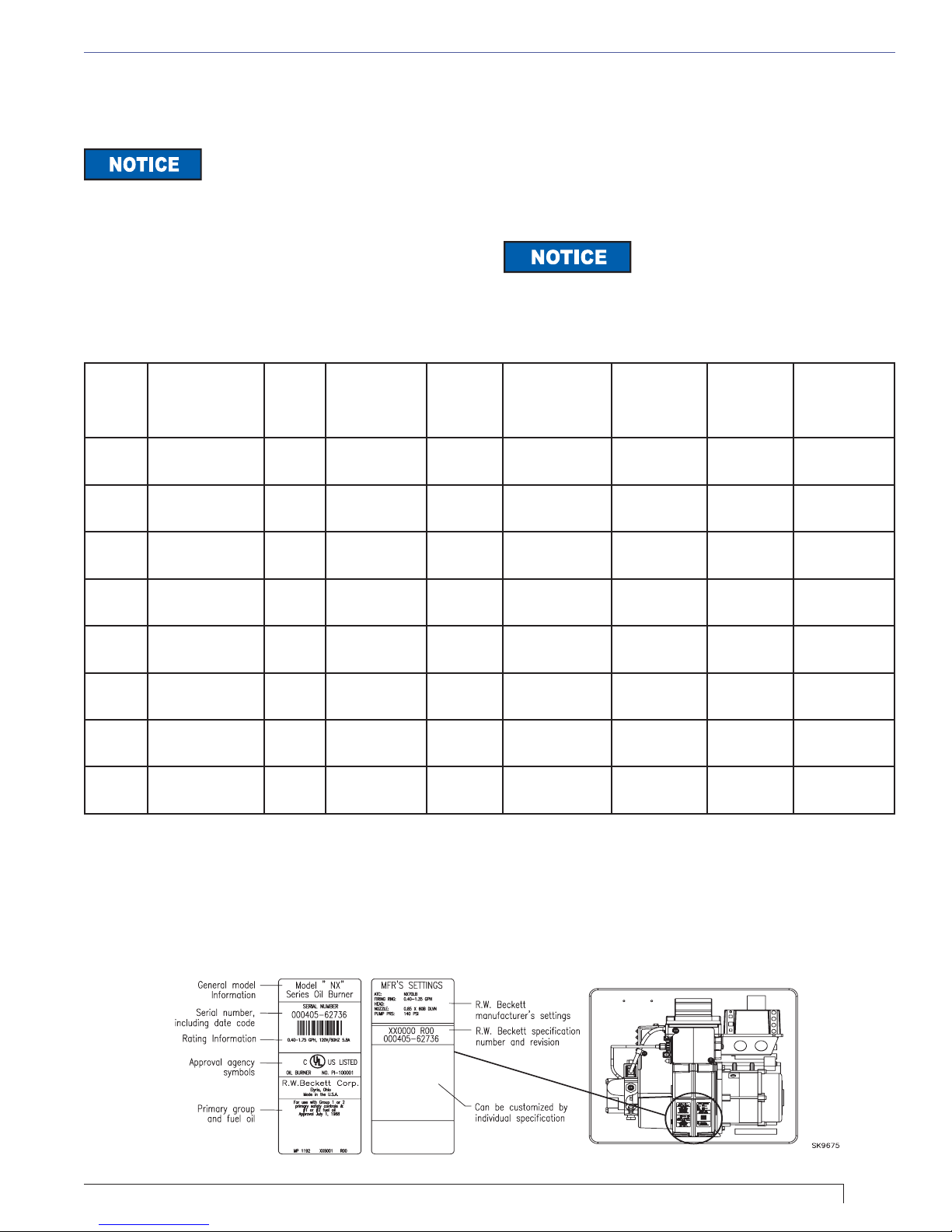
Figure 1. Burner label location
Weil-McLain Ultra Oil NX Burner Manual
5

Section: General Information & Inspect/Prepare Installation SIte
General Information
Table 2. – Burner Specifi cations
Capacity
LB & LC
Capacity
LD & LF
Fuels
Electrical Power supply: 120 VAC, 60 Hz, single phase
Fuel pump Outlet pressure - See Note 1
Air tube ATC code - See Table 3
Dimensions
(with cover)
Firing rate: 0.40 – 1.35 GPH
Input: 56,000 – 189,000 Btu
Firing rate: 1.10 - 1.75 GPH
Input: 154,000 – 245,000 Btu/h
U. S. No. 1 or No. 2 heating oil only (ASTM D396)
Canada No. 1 stove oil or No. 2 furnace oil only
DO NOT USE GASOLINE, CRANKCASE
OIL, OR ANY OIL CONTAINING GASOLINE.
Operating load: 5.8 Amps max
Motor: 1/7 hp, 3450 rpm, NEMA 48M frame
PSC rotation CCW when facing shaft end
Ignition: Continuous duty solid-state igniter
Height (maximum): 12-1/2 inches
Width (maximum): .15 inches
Depth: 9-1/4 inches
Air tube diameter: 3-1/4 inches
Certifi cations/approvals
Underwriters Laboratories has certifi ed this burner
to comply with ANSI/UL 296 and CSA-B139. Low
sulfur #1 and #2 fuel oils reduce heat exchanger
deposits with all burners compared to the standard
fuels. Reduced deposits extend the service
interval for cleaning and improve the effi ciency of
the appliance over time. Low sulfur fuels reduce
particulate and oxides of nitrogen emissions as
well. The Oilheat Manufacturers’ Association
recommends these fuels as the preferred fuels for
this burner.
Inspect/Prepare
Installation Site
Clearances to Burner and Appliance
Provide space around burner and appliance for ease
of service and maintenance. Check the minimum
clearances against those shown by the appliance
manufacturer and by applicable building codes.
*Note 1. See appliance manufacturer’s burner specifi cations for recom-
mended outlet pressure.
Table 3. – Air Tube Combinations (ATC)
Firing rate
(gph)
(min-max) 5” 7” 9”
0.40-1.35 9-Slot NX50LB NX70LB NX90LB
0.40-1.35 6-Slot NX50LC NX70LC NX90LC
1.10-1.75 9-Slot NX50LD NX70LD NX90LD
1.10-1.75 6-Slot NX50LF NX70LF NX90LF
Head ATC codes for usable air tube
lengths:
Notice Special Requirements
THE INSTALLATION OF A BURNER SHALL BE IN
○
ACCORDANCE WITH THE REGULATIONS OF
AUTHORITIES HAVING JURISDICTION.
For recommended installation practices in the U.S.
○
refer to the latest edition of NFPA 31. (CSA-B139
and CSA-B140 in Canada.
Concealed damage — If you discover damage to
○
the burner or controls during unpacking, notify the
carrier at once and fi le the appropriate claim.
When contacting Beckett for service information
○
— Please record the burner serial number (and have
available when calling or writing). You will fi nd the
serial number on the silver label located on the left
rear of the burner. Refer to Figure 1.
Inspect Chimney or Direct Vent System
Fire, Smoke & Asphyxiation
Hazard
Carefully inspect the chimney or exhaust vent
y
system.
Make sure it is properly sized and in good working
y
condition.
Follow the instructions supplied by the appliance
y
manufacturer.
The installation must strictly comply with all
y
applicable codes, authorities having jurisdiction and
the latest revision of the National Fire Protection
Association Standard NFPA 31 for the installation of
chimneys and vent sizing, (or CSA-B139 and CSAB140 in Canada).
Regulation by these authorities take precedence
y
over the general instructions provided in this
installation manual.
Starting with minimum gph fi ring rate, the minimum
1.
size recommended is 6” fl ue pipe with 8” X 8”
inside chimney, unless specifi ed otherwise by the
appliance manufacturer.
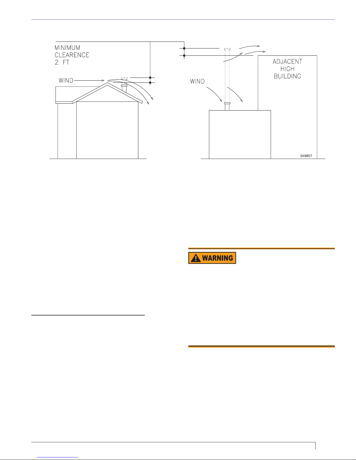
A chimney fl ue shall extend at least 3 feet above
2.
the highest point at which the chimney comes in
contact with the roof, and not less than 2 feet above
the highest roof surface or structure within 10 feet
horizontally of the chimney. Refer to Figure 2.
6
Section: Inspect/Prepare Installation SIte
Figure 2 – Chimney Design - Above the Roof
NOTE: Correct chimney design is shown by dotted lines. Incorrect chimney design, as shown by
the solid lines, may result in down-drafts.
Any accumulation of soot or debris in chimney
3.
offsets should be removed
Any obstructions such as a protruding joint or a
4.
piece of broken tile wedged in the chimney should
be removed.
No other appliance connection should be made to
5.
the same fl ue pipe.
The fl ue pipe should have an upward pitch toward
6.
the chimney of at least 1/4” per foot of length. It
should fi t tightly and should not project into the
chimney.
Any leakage between tiles, around clean-out doors,
7.
or around the vent pipe should be sealed.
Insulated Stainless Steel Chimney Liners
The new designs of high effi ciency oil furnaces and
boilers in conjunction with fl ame retention oil burners
are more effi cient. One result of increased effi ciency is
lower fl ue gas temperatures. As fl ue gases rise in the
chimney, they will cool and condense when they reach
the dew point. The condensation will mix with the sulphur
in the fl ue gases creating sulphuric acid. The acid will
attack the chimney mortar, brick and clay liners causing
corrosion, deterioration and blockage of the chimney.
Eventually the blockage could prevent exhausting the
fl ue gases. Instead, the fl ue gases could vent out the
barometric damper into the living space.
Therefore, it is strongly recommended that an approved
insulated stainless steel liner be installed.
For those installations not requiring a chimney, such
as through-the-wall vented appliances, follow the
instructions given by the appliance and power venter (if
used) manufacturers.
Combustion Air Supply Information
Adequate Combustion
and Ventilation Air Supply
Required
Failure to provide adequate air supply could
seriously affect the burner performance and result in
damage to the equipment, asphyxiation, explosion or
fi re hazards.
The burner cannot properly burn the fuel if it is not
y
supplied with a reliable combustion air source.
Follow the guidelines in the latest editions of the
y
NFPA 31 and CSA-B139 regarding providing
adequate air for combustion and ventilation.
See NFPA Standard 31 for complete details. Appliances
located in confi ned spaces: All confi ned spaces should
have two (2) permanent openings; one near the top of
the enclosure and one near the bottom of the enclosure.
Each opening must have a free area of not less than
one (1) square inch per 1,000 BTU’s per hour of the total
input rating of all appliances within the enclosure. The
openings should have free access to the building interior,
which should have adequate infi ltration from the outside.
Weil-McLain Ultra Oil NX Burner Manual
7
Section: Inspect/Prepare Installation SIte
Exhaust fans and other air-using devices: Size air
openings large enough to supply all air-using devices
in addition to the minimum size required for combustion
air. If there is any possibility of the equipment room
developing a negative pressure due to exhaust fans,
clothes dryers, etc., either pipe combustion air directly to
the burner or provide a sealed enclosure for the burner
and supply it with its own combustion air supply.
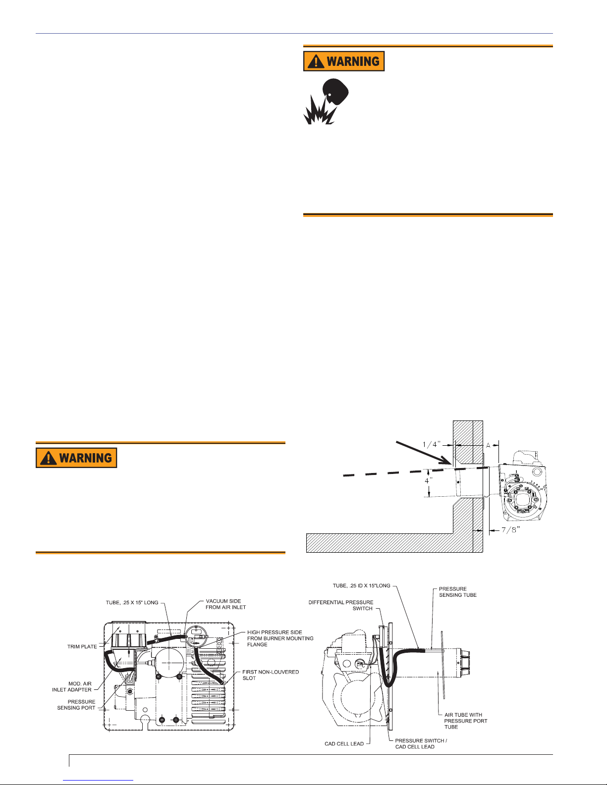
Safety Shutoff for Direct Vent System
The direct vent blocked fl ue safety shut off system, refer
to Figure 3, shuts down the burner if the exhaust fl ue is
blocked and/or if the air inlet is blocked. It recognizes
a blocked fl ue by sensing excessive pressure in the
combustion chamber. It recognizes a blocked inlet by
sensing excessive vacuum in the air inlet adapter.
This system meets the requirements for a blocked fl ue or
blocked combustion air inlet per CSA Standard B140.0.
It is designed to interrupt the cad cell circuit and allow
the control to shut down the burner.
Direct/Sidewall Venting Application
For direct vent installations, follow instructions provided
with appliance and direct vent system.
combustion air is required for direct venting.
When installing an NX outside air adapter (Beckett Part
Number 52018U), refer to the instruction sheet supplied
with the adapter. This kit allows combustion air to be
Outside
Follow the Outside Air Kit
Instructions Exactly
Failure to comply could result in impaired
combustion, appliance soot-up, puffback of smoke,
and fi re or asphyxiation hazards.
Do not attempt to install outside air piping to
y
the burner without using the outside air kit and
instructions.
Connect Outside Air Duct
to NX Adapter
Failure to install adapter properly could
result in impaired combustion, appliance
soot-up, puffback of smoke, and fi re or
asphyxiation hazards.
The outside air adapter must be installed by strictly
y
following the kit installation instructions.
DO NOT attempt to install outside air piping without
y
using the outside air adapter and instructions
provided.
Abundant fresh air is required for proper combustion.
y
piped directly to the burner. The NX outside air adapter
kit may also be used for chimney vent applications that
require outside combustion air.
Mounting dimensions
When using the Beckett universal adjustable fl ange,
1.
mount the air tube at a 2° downward pitch unless
otherwise specifi ed by the appliance manufacturer.
Verify that the air tube installed on the burner
2.
provides the correct insertion depth. See Figure 4.
Figure 4. – Mounting Burner in Appliance
If space between burner
air tube and opening
exceeds 1/2 inch, pack
burner opening with
ceramic fiber refractory.
Tilt down 2°
SK8745
Figure 3. Pressure Switch Installation
8
 Loading...