

Page 1
®
Series 2
Gas-Fired W ater Boilers
Boiler Manual
• Installation
• Startup
• Maintenance
• Parts
This manual must only be used by a qualified h eating installer/service technician. BEFORE ins talling, read
all instructions in this manual and all other information shipped with the boiler. Perf orm steps in the order
given. Failure to comply could result in severe personal injury, death or substantial property damage.
Part number 550-142-783/1012
Page 2
GV90+ Series
2
oAs·FIRED
WATER
BOILER
-
Boiler
Manual
How
it
works
•••
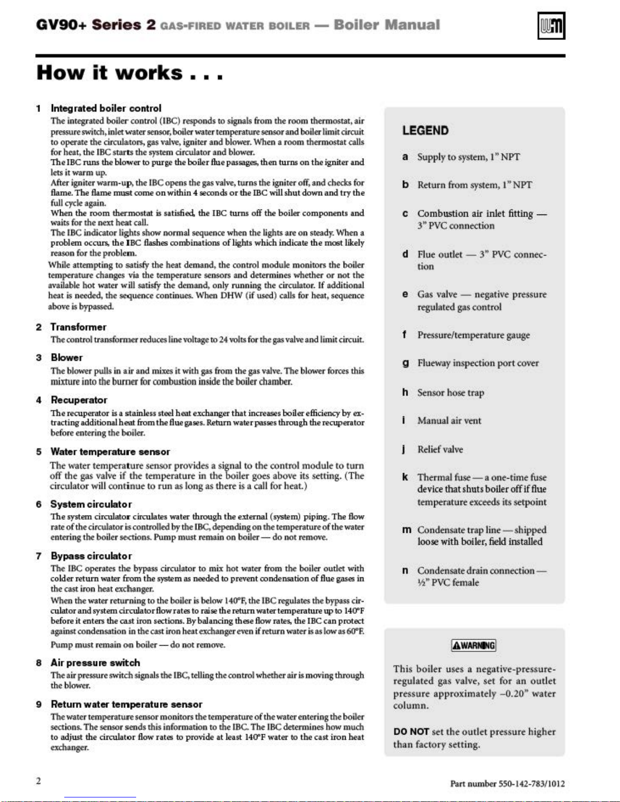
1 Integrated boiler control
The
integrated
pressure switdl, i
to operate
for heat, the I
The JBC runs the biO'\\•
lets it warm up.
Aft
er
igniter warm· up, the I
flam
e.
The flam
fu
ll
cyde again.
hen
the room thermostat
W
wa
i.ts (or the
The
IBC indicator ligh.ts show nonnal sequence wh
problem occurs, the JBC
reason for the proble
While attempting to satisfy the heat demand,
temperature changes via the temperature sensors a
availab
le hot water w.
is needed, the sequence
heat
above is bypassed.
boiler
control (I BC) responds to signals from the room thermostat,
:n
let water sensor, boiler
the
circulators,
BC
star
ts
the
er
e
must
come
next
beat
call.
m..
tll
satisfy the demand, only running
wa
.ter temperature sensor and boiler limit circuit
gas
valve,
igniter and bl
sys
tem circulator and blower.
to
purge the boiler
DC
opens the
on
within 4 wconds
is
satisfied. the IBC turns off the boiler components
flashes
combinations
conti:nues..
gas
When
ower.
flue
passages, then turns on the igniter
vah-e,
or
of
lights which indica
the
control module m
DHW
2 Transformer
The
control transformer
reduces line
vottage
to
24
volts for the
3 Blower
The
blower pulls
m
ixturt into
4 Recuperator
The recupenttor
trading
additional beat &omthefluega
entering the boiler.
before
5 Water temperatu re sensor
The
wat~r
off
rhe
gas
circulator
6 System
The system circulator circulates water through the external
ra.te
ofthecirculator
entering t
7 Bypa
..
The
IBC
colder return "'a ter from the S)'Stem
th
e cast iron heat exchanger.
Whe
n
the
culatorand
it enters the cast iron sections, By balancing these
before
agai:n.st
condensation
Pump
mU$t re
i:n ai:
r and mixes
lhe
burner for coml
is
a stainless steel beat exchang
t~mptralur~
valv~
if
the
wlll conrinue to
it
with gas
xu:tio
n in
ws,
sensor
provides a signal
temprratur~
run
in the boiler goes
as long as there is a call for heat.)
circulator
i:s
he boil
er
.se<tion$.
controlled
by
Pump m
the
u.<
IBC,
n rema
circulator
operates the bypass circulator to
as needed
water
returning to the boiler
sy
stem circulator
in
the
main on boiler-
flow
cas
t iron heat exchanger e\'en if return
rates
do
Is
to
not rem
&om
side-
the-
er
that increases boaer e
Return waterpasws through the recuperator
depending on the temperatu
in
on
mi.x
hot water
to
prevent condensation
below IW F. the I
rai
se
the
return
m-e.
When a room thermostat caUs
rurns the igniter off,
the me will shut
en the lights are
nd
determines wheth
the
ci:
(if
used)
caJJs for heat. sequen
gas
th
e gas
valve.
and
down
on
steady. When a
te
the most
onitors
er
rculator. If additional
valve
and limit
The bla\\'et
boiler chamber.
fficiency
to
the
conrrol
(S)
boiler -
fro
BC
water temperature
flow
modu
abo~
its setring. (The
'Stem)
piping, The
re
do
not
remove.
m t
he
boil
er
of
regulate$
rate
the
s.
the IBC can protect
water
Is
flue gas
as low as
air
and
checks for
and
try
the
and
bkel
the
boiler
or
not t
he
ce
ci:rcuit.
forces
this
by ex·
le
to
turn
flow
of
the water
outlet with
es
bypass
ci:
up
to l40'"
6Cr
in
r·
f.
LEGEN
a
b R
c Combustion
y
d
D
Supply to
etu
3"'
FJ
ue outlet -3"'
rn from
P
VC
system>
connecti
1"'
system,
air
lnlet fit
on
PVC
NPT
I" NPT
ting -
conntc·
tion
e Gas
vaJve
regulated
- negati
gas
control
ve
pr~ss
urt
I Pressure/temperature gauge
g
FJueway
inspection port
CO\'tr
h Stnsor hose trap
Manual air
Relief
k Thermal
device
te:mptrature exceeds irs
m Condtnsate trap line
loose
n Condensate drain con
W'
PVC
F
vtnt
vaJ\ ·t
fuse-
a one·time fuse
that shuts boiler off
-sh
with boiler,
field
nection-
female
if
flue
strpo
int
ipped
installed
8
Air
pre
..
ure switch
The
ai:r
pressure switch signals
the blower.
the
IBC.te U
ing the control whether air is moving through
9 Return water temperature sensor
The
water tempera t
sectfons. The sensor sends this Information to the
to
adjust the cirrulator
exchanger.
UI'e
sensor monitors
fl
O\\'
rates
the
temperatu
to
provide at least 140'"
2
IBC
re
of
. The I
the water
P water
entering
BC
determines how m
to
the
boiler
the cast iron beat
uch
Thi
s boile r uses a negarive·
tgulattd
r
pressure
column
00
ha
n facto ry
t
gas valve, ser for
approximately -0.
.
NOT
set rhe
sett
Pan
outle
ing.
number 55
prtssurt
an outl
20"'
t
pr~ssurt
higher
0-
142-783/1012
-
et
water
Page 3
GV90+
Series
2 GAS·FIRED WATER BOILER -
Boiler
Manual
GV90+
Series
2 Water Boiler
Part
num
ber 550-
14-2
-783/10 12
3
Page 4
GV90+
Series
2
oAs·FIRED
Contents
How
it
works
.....
GV90
+ Water Boiler .
Pie
aM read belore
Pr
epa
re boilerlocat
Installations m
High altitude i:nstallatfons
Residential garage installation
Check orifice plate - replace
Install condensate uap. . .
Install h
required
Rotate t
Perform hydrostatic pressure
In
sta
ll water piping
General
Install reliefvah-e
Exp
ansion tank
Sys
tem water piping m
Orculators
Simplified pipe/cirrulator selection
Baseboard system piping - ORCULATOR
'ZOning
Baseboard system piping -
'ZOning
Radiator system piping
Single·
Ad;wt
Multi·
wne
Piping snow melt systems
snow
melt/space heating
Water
chiller systems . . . . . . . . . . .
u.<
igh
altitude
{onJy above
he
boiler into position
pipi:
ng informat
•..............
.................
(pri:m
arylseco
(d
irect connection)
wne
radiant h
b
alanci
ng
radiant heatiog system . . . .
Multiple boil er installat
Placing
mul
tiple
Conuolling multiple CV90+ boilers . . .
Piping multiple CV90+ boil
Multiple boil er water
Easy·Fit•
piping installation . . . . . . .
Ventin g & air-
When removing a boiler from an existing
common
Existing vent
Provi
Vent and
DIRECfVENTinstallations
DIRECT
Combust
Ma
RECT
Air manifold sizing . . . . . . . . . . . . 3 1
Commo
in
sta
ven
t system . . . . . . . . . . .
de
nifolded combustion
llati
tes
combustion air:
air termination options
EXHAUST
io
n air contamination: . . . . . 30
VENT multiple
nwe
alth of Mlls
ons
. . . . . .
Vent termination req uiremen
DIRECT VENT- Boiler room air
ope
nings . . . . . . . .
DIRECT VENT-
ve
ntfair plate. . . . . .
DIRECT VENTr
ate pipe
s. . . . . . . .
.
p~eding
ion
n
fonow
these codes:
..........
air press
S.SSO
........
ion
.............
eth
ods
ncf
ary) .......
..........
eati:
ng
vah<S
, , , , , , , , , , 19
or
;Systems.
boi~s
. . . . . . . . . .
piping
genKal ......
t procedure
..........
installations
air
boib
inslallations
Sidewa
Sidewa
...
.......
...
.......
if
necessary. 8
.........
ure switch wh
feet)
......
......
t
est
.....
........
.......
...
ZO
NE VAL
........
or
heat
pum
combinati
ions
ers.
on
. . . . 2 1
....
. . . . .
•...
........
.....
.......
.....
option
(or
Dl
. . . 3 1
saohusetts
......
ts
..
......
ll
with W-M
......
ll
with oepa·
......
VE
WATER
DIRECT VENT
.2
concentric .............
.3
DIRECT VENT
5
rate pi
pes
..............
BOILER
- Sidewa
- Vertical with
6
DIRECT VENT
6
conce
6
1
ntric
Concentric termination assem
(sidewa
9
en
Ve
nt
9
10
II
12
12
12
13
IS
IS
IS
16
16
18
p 19
20
and a
nections
DIRECTEXHAUST&DIRECTVENT .
Follow
termination instructions . . . . . 48
Installing vent a
DI
RECT
DIRECT EXHAU
ope
nings
Combustion
Siring
combu.<Jtio
Special constderations. . . . . . . . . . . 49
9V90+ boiler
tn room . . . . . . . . . . . . . . . . . . .
Air openings . . . . . . . . . . . . . . . .
CV90+ boiler
roon1 . . . . . . . . . . . . . . . . . . . .
DIRECT EXHAU
- Vertical with
.............
ll
or vertica
ir
pipi
..............
nd
EXHAUST
..............
ai:
r provision. . . . . . . . . 49
n air openings . . . . . 49
WITHOUT other appl
WITH other
DIRECT EXHAU
22
23
23
23
23
24
24
29
29
29
30
30
30
30
·
34
35
36
37
39
Gas piping
Connecting
Natural Cas . . . . . . . . . . . . . . . . .
Propane Cas . . . . . . . . . . . . . . . .
Wiri
ng
Field wiring. . . . . . . . . . . . . . . . .
Sta
rt-
Freeze
Clean system to
Water
Antifreeze . . . . . . . . . . . . . . . . . . S9
F
lll
and
Use
inhibit
Check/Ve
Check
Check
Verifygas/airorificeplate . . . . . . . . . 61
Check thermostat circuit(s) . . . . . . . . 61
In
spect/fiJI condensate syst
Final checks before starting boiler . . . . 62
Adjust
Aju.•
n boiler control
Bo
iler
st
art
To
If
boiler does
Ch
eck
Cas
vatve
re.tONLY
Final checklist
.............
gas
suppty pi ping. . . . . . .
...............
up
...............
protection (wh
remo\>e
chemistry . . . . . . . . . . . . . . S9
test wa.ter system . . . . . . . . . 60
or
supplied with boiler . . . . 60
ri
fy water chemistry. . . . . . . 60
imllit:or
boiler control srttinp . . . . . . . 62
c.oncm
for
gas
leaks. . . . . . . . . . . . . 61
Eco
nomy settings. . . . . . . . . . 62
the
boiler
nots
system
and
adjustment - attitude
.................
...............
-
Boiler
ll
with 3"
41
-·
43
3"
45
bly
l)
ng
........
and
boiler con-
47
48
48
air piping . . . . . . . 48
ONLY
. . . . . . . .
48
ST - Boiler room air
49
iances
50
50
appliances in
ST - Sidewa
ST -
Ve
rtical
ll
•..
..
50
51
53
54
S4
SS
SS
55
S6
59
en
u.W)
. . . . . . S9
sediment . . . . S9
tnr:
ion
an
rualy
. . . 60
em
. . . . . . 61
setti:nSJ>
. . . . . . . . 62
.............
tart correctly
boiler after start·up
.....
O\'ft'
62
62
..
62
S.SOO
63
64
Manual
Department of
IBC
(Sequence
Operating lnstrustions
Annual start·up a
nance schedule . . . . . . . . . . 68
Annual start-up . . . . . . . . . . 69
Address reported problems . . . . . . . . 69
Inspect boiler area . . . . . . . . . . . . . 69
Inspect boiler interior . . . . . . . . . . .
Inspect condensate drain syst
Inspect
Inspect gas piping . . . . . . . . . . . . .
Inspect
Check water syst
Inspect expansion tank . . . . . . . . . .
Inspect
Inspect
Inspect boil
Inspect igniter . . . . . . . . . . . . . . .
Inspect t
Inspect
Inspect
Inspect blower mot
Inspect oiled·beari:ng circulaton . . . . .
Inspect supply temperature sensor . . . .
Inspect boiler relief
To
comple1< Annual
startup
Review
Se
rvi
ce
Cleaning boil
To remove the blower assembty . . . . . 73
To
dea
n heating surfaces . . . . . . . . . 73
To
dea
n
To
replace blower assembly
Inspecting and
Tro~eshooting
VERIFY
SERV
ICING
Before troubleshooting . . . . . . . . . .
Check the following . . . . . . . . . . . .
Checking the air pressure
Ig
niter
....................
Gas
Valve
Blower
Thermal
Return temperature sensor . . . . . . . .
Suppty temperature sensor . . . . . . . .
IBC
(integrated boiler control) . . . . . .
IBC
indKat
IBCin<iiolt«
Installation a
ce
rtificate . . . . . .
Replacement
Dimensions
Handling ceramic fiber
glaoo
mat
NOTES ..............
Energy
of
eon-.>liance
operations)
..........
.......
nd general maint
e:n
l . . . . .
all
pipi
ng
for
leaks . . . . . . . .
the
water system. . . . . . . . . .
e:n
l chemist
air
openings . . . . . . . . . . . .
ven
t system and air piping . . . .
er
heati
ng
e:nlpe:ral'Ute
additional
gauge5
and
with
conuok
. . . . . . . . . . . . . . .
or
checks . . . . . . . . . . . . n
owner.
& maintenan
er
heati
the
burner
deaning
ry
. . . . . .
surfaces
mi.xi:
. . . . . . . . . . .
valve
Slan·up,
. . . . . .
ng system . . .
and
cutotfs
. . . . . . . . . n
perform
. . . . . . . . . . . . n
ce
. . . . . . 73
ng
surf:lces
. . . . . . . . . . . . 74
. . . . . 73
........
the recuperator 74
..........
PROPER
Housi
fuse
OPERATION
.................
. . . . . . . . . . . . . . . . . .
ng
. . . . . . . . . . . . . .
. . . . . . . . . . . . . . . .
or Lights - lockout modes. .
l
iglu>-non·~m<><l<!
nd
service
parts
and
ratings. 1
AFTER
switch
. . . . . 76
. . . . 91
and
fiber-
erials. 106
. . .
.
65
66
67
e-
69
69
69
69
69
69
70
70
70
70
70
71
71
71
71
71
71
74
76
76
76
76
77
77
77
77
78
78
79
79
.
79
90
02
107
4
Pan
number
SS0-142· 783/1012
Page 5
GV90+
Series
2
OAS·FtRED
WATER BOILER -
Boiler
Manual
Please
Hazard
The
bring attention
to i
!A
NOTIC
IAwARNIN&l
NOnCE
definitions
following
mportant information
CAUTION 1 lnd
E
read
defined
lnd
perSona
damage.
lnd
perSonal i
damage.
minor
Jndicares
Opt-ration o r maintenance th
no
Installer-
man
boiler> before installin
gi
Uller-
he-ating installer/service technician.
Jn:f'onnation
User - Ha\'t this
qualified service technidan, at
fajlure
sevtrt personal injur
da.mage.
W~itt
the In stallation certificate
terms
to r.he prestnce
icares pr
l injur-J'•
icares pr
icares presence
ptmna
t related
ual
and
.. ·tn.
This manual
to
in the CP numbtr
before
are
used
of
concerning
t.Sence
of
dearh
t.Sence
of
njur)
'• dearh
of
l inj
ury
speda
l
in
to
ptrso
nal inj
Read
all
all
other in
ManuaJ fo
comply wi
throughout
hazards
boiler serviced/inspected by a
y,
of vari
the life
of
hazards thar w
or
substa
hazards that can cause
or
substantial proper
hazards that
or proptrty
srructions
ury
instructions. induding this
for
g.
Perfonn steps in the order
is f
or
r your referen
th th
death or substantia] proptrty
in the space provided on
on
on insrallation.
ar
are i
or
proptrty
mation
use
only
lea
st annually.
e above could result in
page
this
ous risk
the product.
lll
nt ial
will
damage.
mportanr
shipped with
Refe
90
shown.
\Vhen
call
ing
or writing about the
have the boil
label and the
Consider piping and installati
boiler location.
Any claims for damage or shorrage in shipment
must
company by the consignee.
Commonwealth
When the boi
l-er
M..,.chu.setts, comply
This produ
fitter
If antifreeze is used, a reduced pressure back-flow preventer
d.,;ce
tf sidewa
ct
must
.
sha
ll
be
JI
\.'tnt or venr/air is insralled>
er
model nwnber
CP
number
be
filed
immedlatelyagainst
of
Massachusetts
is installed within the Commonwealth
with
<he
be
installed by a licensed plumber or
uStd
.
from
following.
boiler-
from
the
the boi
on
when determining
the
transportati on
see
instructions on
page 34.
proceeding
~WARIM
manual
cause
or
can cause
by
a
r to User's
ce.
if
not already
boiJtr
le
r jacket.
to
lt•ttls or
sevt-
rt
property
sevt-
rt
ty
bur
damage.
th
qualifi
ed
Please
raring
of
gas
When ..,,.,.;cing boiler-
To
before performing maintenance.
To
performing maintenance.
This boil
materials.
on
Boiler operation -
Do
to
Should
tMit
sup.
at
Do not
woter.
e
cian to inspect
the control system and any gas control that has bft.n
under
Combustion air -
DO
It a rltk
Carbon monoxide detector-
Fo
tor is requir
oxide dttecror must be wired
circuit
Fo
that
is
Boiler water-
Thoroughly
neo
exd1anger
due
Do
compounds
system
property
LNkoln
to P<8Yenl
In
wat-er will
exchangers reduces heat transfer,
ri
als,
by
Do
ca
Freeze protection fluid• -
NEVER
Use
systems. Foll
manufucturer.
placeme
m
I
Failure to adhere ro the guidelines
page
can resu
Cleath
or
avoid electric shock, disconnecr electr
avoid
severe
er
contains ceramic t'ibtr
Refe
1
.
r to the
06.
flow
page
not bloc.k
boiler
""erhNUng occur or g
off,
DO
t
~
ci
NOT
rculator.
P.Iy
ll in
severe
substantia] proptrty damage.
burns, allow
WARNING
of combustion or \
personal i
boiler ro cool before
and instructions
..
tum off or disconnect electri
Instead>
sh~r
off the gas supply
a l ocanon externaJ to the apphanct.
UM
thla
Immediately
wate
r.
NOT Insta
of
combustion air contamln.Uon.
r
OII'Cid
Exhaust uni
ed
as
the boil
r Direct
stro
V•nt
i.s
wirtd on the same electrica
ngly recommended.
flu
ted )
to
removeS<'dinlenl
can
to sedimtnr.
not
lL~t
JH:trole
in boiler
may
bedamage<t.
call a
tht
boiler and to
ll
combulllon air Intake whwe there
in the boil
er.
units, a carbon monoxide dttecror
sh
the system
be
damaged by build-up or cor
um-based
S)'Stem.
boiler H any
~h
qil3lifi
ts,
a carbon monoxi
er r
oom
..
ed s
rtp
l.act any
. The carbon mon-
on the
l d rcuir
(without boil er con-
TbehbUI-ellic.iencyheat
deaning
Gaskets
This
can
r
esu
damage.
boiler
0<
piping ,.....t
• ciOMd-toop system. Contin
make-
not
n cause heat exchanger to crac
only
sr.alling the n
moke-t~p
rtduct
an
<I
cause.s
up
water
add
cold
u.se
automoti\·t or standard glycol antifrtt:ze.
freeu-protectlon
ow
nt
boiler system that has used gl
woter. Use
boiler life. Min
tanure. Addition
can
cause intern
w.ter
to
aU guidelines gi,·
Thoroughly
ew
boiler.
be
repeiN<I
thlo boiler
ual
eraJ buil
overheats the mate-
of
oxyge
al corrosion.
hot
bolter. ThennaJ shock
k..
fluids
made
tn
dean
br.
ana flush
on
thi.s
njury,
ica
J supply
and
fiber~lass
<entilation
aupply
air
11111
to
cal
_.,under
ervice
techni-
va:
rt
of
de
detec
same
electri
cal
as
the boiler
ros
ion
or
and seals
lt in substantial
staling
in
the
ot once
ONLY
fre.sh
make-up
dup in heat
n carried in
for
hydronic
the antifreeze
apy
)'cO
re-
I before
-
Part num
ber
550-1+2-783/1012
5
Page 6
GV90+
Series
2
oAs·FIRED
WATER
BOILER
-
Boiler
Manual
Prepare
Installations
Lo<a
l,
srat:t,
provincial, national codes, J
National
Standard for Controls
Boilers,
National
For Canada only: Bi49.i or Bl49.2 Installation Code
Canadian
The
GV90+
perrormance criteria when boiler underwent tests specified in
-latest
1
MOneE
High
GV90+
See
Figure 1 for estimated
input. Multiply the boiler
est
imated high aJtitude i
wi
ll
also
fur
ther info
No mo
s.soo
be
musr
kit instructions, page 10. Note that
checked (and adjus
N
OTICE
Fuel
ANSf/ASME
Ele
EJectricaJ
boiJt r
edirion.
1 For
rhe special instructions located
Insta
from
Al
bo
substantial proprrty damage.
altitude
boil6'
<Mirols
h
ave
a min
rmation.
difications
fee
t above
changed
DO
ar
for DIRECT
altitudes a1x
boiler
must
Gas Code, ANSI Z223.1
ctrical
Code
gas
manifold
th
e Commonwealth
ll
the boi
ti'lpplng
lowin
g.
iler faiJu
Installations
•utofililitAIIy
or
impact on input.
to the
St:a
level. For higher
to
aspttial
ted
if
NOT oldowall
alrirud~s
follow these
and
Safety
CSD-t, when
Code
Pa
rr 1 and any local codes.
and
kr
so
control S)'Stem componrnts
or
spraying water
these
compone
rt,
resulti ng in
inp
ut
at
sea
level
input
nput
. Note that the length
boiler should
high altitude switch.
necessary) followin
vtnt
abo\re
s.soo
VENT
app
we
s.soo
fee
location
codes:
aws,
regulations
- latest edition.
Devices for Automatically Fired
r~uirM.
con
tro
ls
m~
of
Massachusetts, read and foll
on
page 34
or rak'l
nts
to
become wet
severe
personal i
todutt input
altitude as a percentage
b)• this
Refer
be
nece
e-levations
the
gas
DIRECT EXHAUST
feeL
Si
lications (
t
wit
ptrc~ntage
to
the vent
ssary
. the air pressu
Refe
\<alve
outlet pressure
g insrructions on page 63.
dewa
JJ
ducted
and
and
safe
lighting
of
dur
njury,
h
ina~ing
of
the •tenting systttn
supplement l'
for
installatio
r ro the high altitude
APPUCAnONS
venting is only
combustion
ordinanc~.
CSA
C22
.1
and
other
ANSI Z21.13
this manual.
~
ing Optrntion.
cou
ow
protected
ld
cau~
a
death
or
alritudt.
of
St:a
level
to
obrain the
..,r
ns
up
to
re
switdl
mu~
be
allowed
air) nt
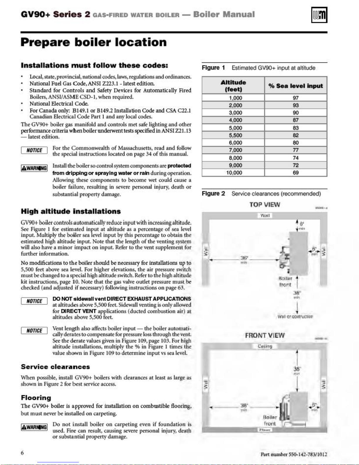
Figure
Figure
0
~
1 Estimaled GV90+ input at altitude
Altitude
(
fee
t )
1 000
2,000
3,000
4,000
5000
5,500
6,000
7,000 77
8,000 74
9.000 72
10,000
2
Service clearances (recommended)
%
Sea
leve
97
93
90
87
83
82
80
69
l
Input
TOP VIEW
W"'l
~
6'
i
ml"
36'
...
i%
-~"""
lir
8GIIL>r
rront
:w
••
I
W•ll
cr
oo:nn.ctlo-1!
'
-··
~
,.
....
>
Ve
M
OnCE
Service
When possible. insrall
shown in Figure 2 for best service
nr length
caJiyderates ro compensate for pressurt
See
the
alrirude
\'ll
]ue show-n in Figure 1
clearances
aJso
affects boil
d~rate
values
inst:a
Uartons, mulriply
GV90+
bo
given in
09
ilers
wir.h
access.
er
ro
Flooring
The
GV90+
bur
mu.sr
6
boiler is • ppr
never be install
Do n
ot
ins
used.
Fi r
~
or
subsran
ove
d for installation on combustible flooring,
ed on carpeting.
rall boil
can resul
tiaJ
er
on carpeting even if foundation
t,
causing severe personaJ i
property damage.
input-
Figure
ihe%
d~ermine
dea.rances at least as large lt.'i
the boil
&oss
109,
in
er
through
page 103. For high
Figure 1 rimes tht'
input
vs
sea leveL
njury,
auromati-
the
vcnL
death
i.-.
::1
3:
FRON
36"
rln
T VIEW
C~lna
R.,.,
hool
Fl
..
..-.
l•.an
num
l
I
~
-
••
!
Ql
ber
550-l-42-783/10
-·
s·
-
~-
j
12
Page 7
GV90+
Serie
s 2
fiA!i
-fll
~o
w
_".,.
IIOlL-1!11
- BaU
er Manua
l
Prepare
boiler
location
Foundati.on
Providt a .sQiid br:lck
is
possible:
When
the
floor ca.n
Whto (hr:
boiJI(-r
When a high
bigh
c:-nOug
-as
the
t.Xmd(nsat~
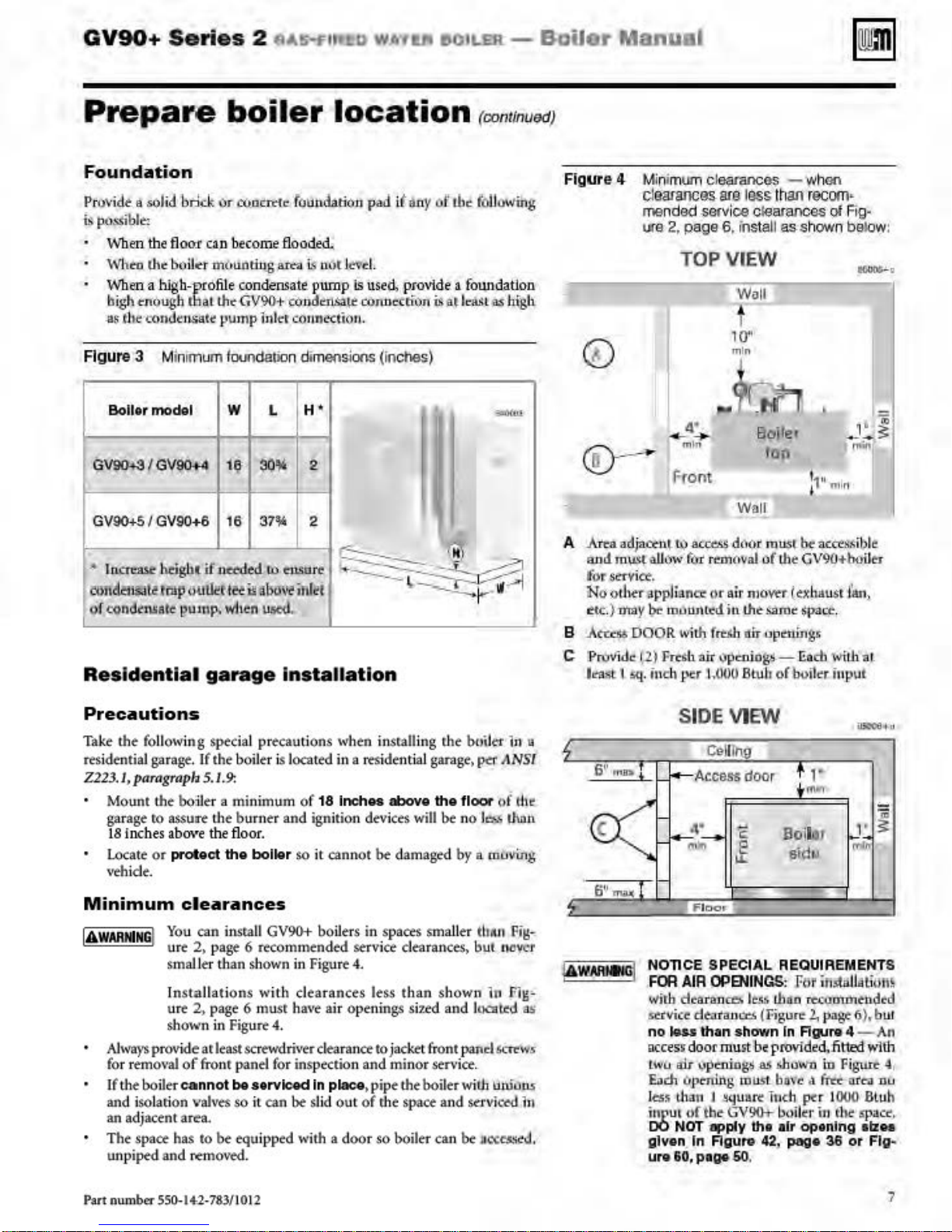
Figure 3 Minimum fll<J!ldalion dimeosians (inches)
Boll
or
model
G~
GV90+S I GV90
• lnCI'tllk
e;mdcmioll
vf
/
GV90+4
heighl
!rnp
condc"nsate
Residential
or
<Q.ocmo
becoll)f
mbuntin_g
-profile
h tl:\at lhr: GV90+ c(mden,sat,t
condensaie
pump inl
w L
11!;
+6
16
if
nttded
iltlil<U~
puJnp.
ilHilluv~
v/Jttn
garage
foundation
flood~
ak:il
is n
ot l.e're
pump
t-r
c(ui.ne<tio
H'
LU
auo
2
2
re
inlet
301'
371'
u&erd.
Installation
~
pad
it
llny
l.
is u
sed,
provide a foWldaiion
cOnnectil)n
u.
-------=
~
---~--
oi'
is
at
the
least
(continued)
Figu
following
as
hfgli
""""
A ..Arta
+-·
~
::..,
B
C !ProVide 1,2) Fresh ait
re 4
Min
imum
ci~(J$
clearancas
mended
ure 2, page 6, inslali
$ervice
TOP
me
VIEW
~
...
4_:..
m
in
Fr
ont
adjact:n~
and
m\!S~
f
ot"
.se-rvict-.
iNo
o
tJ~r
etc
.)
n'my
..Aca.~DOOR
l~mst
1 5q. inch p
«>
allow
for
...
pplilnC'I:'
l,t
m.JwHel;l
IY
er
ac:-cos
~(tval
or
a.
in
ilh
fft'.AA
~
pccios<-~odl
UM)U
- whoo
lliSs than
clearances ol Fi
rocom
as
shown below:
Wall
t
10"
min
f~
El<>iler
t
op
Wal
l
d<l(tl'
mus
()
( l,he GV90,..boile.r
i.r
mowr
th~
samt
nir
upenin~tr.:
Btu'l1
.
~
lko
acct!1~ible.
(~x
haust
fpacc.",
Wfth
or
bolter input
•
1
l
1ln,
g-
al.
Precautions
Take the following
residmtiaJ garage. If the boiler is located
Z223.1,parngraph
Mount
garage ro assutrt the burner
18
Locate
\'fhi
the
inc.bes
or
de.
Minimum
IAWAHNING
I
Alwa
ys
provide ar least screwdri\'fr clearance
for rt:mO\'al
If the boiler c-annot
and iso
lati
an adjacent area.
The
space has
unpiped and
sptcial precautions when installing r.he builer ln u
5.1.
9:
bo
lltr a minimum
abO\~e
the
fl
protect
the
oor.
bolktr
of
18
and
ignition devices will
so
it
clearances
You
can
in.s
mll
GV%+
ure
2.
page 6 recommended servi
smaJ
Je:r than
I
nstallations with
ure
2,
shown in Figure 4.
of
fronr
on
valves
to
~
shown
page 6 musr ha\'f air
pane-l
be
serv~
so
it
can
be
equ
ipped with a
moved.
boiJers in spaces small
in Figu
clearances less th
for inspection
In
be
sl
in
a residential
Inches
cann
re 4.
openings si
place
id out
door
garage)~
above
the
be
ot
be
damaged by a muving
ce
dearances.
an
shown
ud
and
to
jackrt front panel
and
minor
sen·ice.
. pipe
the
boiler
of
rhe
space
and
so
boiler
can
ANSI
floor
of
the
no
J~
thon
er
thA
H Fig-
but
n
ever
lP Fig-
l
tKat.ed
St."t't'\'f'
with uruuus
krvic«< iu
be
ue<:cs.'icd.
as
SI
DE
VIEW
Coll
~
6
1'
mll
ll'
l
- Accessdoor
lhg
t ,.
+
m.,
1i
4.
co:::
11
6
l'I'W(
-i:
l
f'
NOllCE SPECIAL
FOR
AIR
~-lith
dta
&t:tlfic.e dt:tr'ances {Fig
no
klu
occess
s
door
LWO
iti.r
Each
ltl)t-nirtg, mlJst ba\
l
es~
t.lun J
iurut
uf
DO NOT
given
ure
60,
-
...
£
Flocn
OPENINGS: Flif
tan
ceo.
than shown In
must:
ypw.io&S
~uttre
tt,e-
GV90+
apply
In
Aguro
pa;.
50
Bo11~l
"
&i
dll
REQUIREMENTS
lt.'.-t
than
ure
be
lht
.
Agure
provided,fitted
a5
shllWn io
t:
inch ptr I
boilc:r iu the spacr.
air
aptnlng
42, page
it;,tiill•ti<lill
rec~:J"mm
2.
pagt 6).bul
.i
ft«
36
~
,r
"""
tndtd
4 - An
wlth
Fit.'l.trt'
nl'ea
nu
OOtl
Btuh
alzH
or
FJg
4
~
..
Part num
ber
550-1+2
-783/10 12
7
Page 8
GV90+
Series
2
oAs·FIRED
WATER
BOILER
- Bo
ll
er
ManuaJ
Prepare
Check
orifice
The COf'l'tltCt ortflce plate must be
will
property damage. The
gas
the
plate -replace
resuJt in
ortflct
propane.
Natural gas:
For n
atura
l
gas
installations.
marking.
stamped with
saler. The boil
stamping.
It
must
anothe
er si
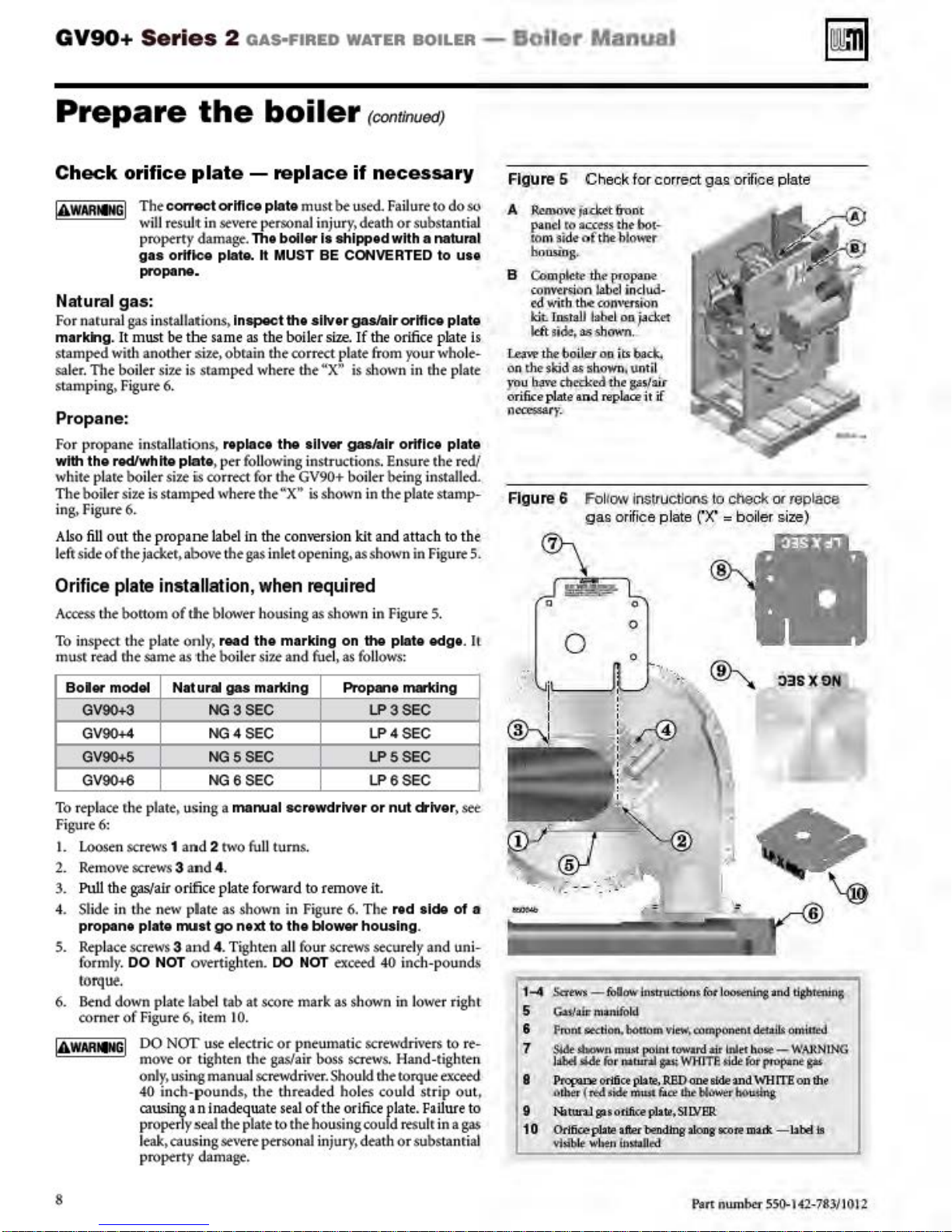
Figure 6.
be
the
r si
u,
7.t
is sramprd where
Propane:
For propane insrallarions,
with
the
redlwhtte
white plate boil
The
boiler
siu
ing. Figure 6.
Also
fill o
ut
lefrside
of
the jacker,abovethegas inlet opening. as shown in Figure 5,
plate
er
siu
is
co
is stamped where the
the
propane
boiler
severe
persona] in
bolltrls
plate. h MUST BE CONVERTED
Inspect
same
obrain the cor
nplac•
as
the
the
boiler
the
sUver
rtct
the
sliver
(continued)
if
necessary
used. FaiJu
jur
y.
death
or
substantial
shipped
size.
plate from
..
X
"'
with a natural
gas/air
If
the
ortflee
orifice
your
is shown in rhe plate
gas/air
orttlc•
rt
to
to
plate
who
, per following instructions. Ensure the
rrtct for the
label
in
GV90+ boil
1
'X
..
th e
com-ersion
er being installed.
is
shown in the plate stamp-
kit
and attac.b
do
so
uu
plate
le-
plate
r
~
to
the
Figure 6 Check
A
:R.emow
p
an~l
to
.m
m
~ide-Qf
housing.
B Co.
mp
lcte1t,el'fopane
connrsion label ind
«1
Wit
h
th.e
kit.
Insr.a.IJ
ld't t
ida
is
~the
on the skid
yo
u
~
ri6ce
11cce658t
Figure 6 Follow insv
,
f;Joil~
8$
~love
chocked
plate and
y.
j
s.cktt.
&oot
aa:~$
thf' bot-
t
he
bl
COP\ttniQn
labt.
l oo. j.:td:d
11$
Mlawn.
oo.lts ba
shown,
thr
n!pl.aoe
gas
or.
for corr
ect
ower
ud
-
ck,.
!Jn
til
g;oi/mr
it
if
uctJons to check
ijice plate
gas
o
r~ice
rx·
= boiler size)
plate
0<
replace
Orifice plate installation, when required
AcctsS the bottom
inspect the plate only.
To
musr read rhe same as ·the boil
Boltr
model
GV90+3
GV90+4
GV90+5
GV90+6
To repl
ace r.he plate . using a maooal
Figur
e6:
1.
Loose
n screws 1
2.
Remove
3.
PuiJ
the
4. Slide in the n
propane plate
5.
Rep
lace screws 3
formly. DO NOT overtighten. DO NOT exceed 40 inch-pound$
torque.
6. lknd down plate label rabat score mark
of Figure 6. it
comer
jAwARtM
I
of
tile blow·
Nat ural
and
er
housi
read
the
er Si7.t
gas
martdng
NG3SEC
NG4SEC
NG5SEC
NG6SEC
2 two full
ng
as shown in Figure 5.
marking
and
on
fuel, as foll
Ptopane
scn
wdrtver
turns.
the
screws 3 and 4.
gas/air
oriffice
plate
forward
ew
plate
as
shown in
nut
go
next to
and
4. Tighten
em
10.
DO
NOI'
use
electric
or tighten
move
onl
y,
usi
ng
4()
inch-pounds. the threaded holes could str
causing
an
properly seal the plate
leak. causingse\rere person
property damage.
r.
he gas/air boss saews. Hand-tighren
manuaJ
SCTtWdri\·er.Shou
inadequate
to
remove it.
Figu
re 6. T
the
bloww housing.
all four screws securely and uni-
as
shown in lower right
or
pnewnatic screwdri\·ers
ki
seal
of th e
orifice
to
the housing could
al
injur
y,
death or substantial
plate edge. It
ows:
mar1dng
LP3SEC
LP4SEC
LPSSEC
LP6SEC
or
nut
Qotver
he
nd
side
rhe torque excted
plate. Failure
resu
to
ip out,
lr in a
.
of
see.
a
re-
to
gas
1-4
.!ia'twi - follow
S
C:a~a.il:'
manifold
6 Fn,nl
7
8 Ptopule Otifict plate.RBDaoe6ideandWHIT.Eon
9
1 0 Orificepbte after bendtng along
~tion.,
$Me
$bcw.ttt mu.tt
llibtf
fll.de
4tbi:r (
ttd
Natw-a:lg:uotifio:e
\liu"b
lt
wl~
lt•itrt~t:Ubnt
lO
skit
r 1At
im.UJ
bouam vi
ew,
po;lnt
t
unl
~
n\11St
~
plate.SIIYE!R
IM
(I'Wa
WH'ITI:-d
dw
fot
l
~lns
campon
nu
dtull.t omiJkd
rd
-aif lltlt1 h
~rhou..~
de
Kote
ttte-
for propane
mack
and lir;htal.ins;
WARN
-
l.tbel
lNG
gM
th~
111
8
P3n
num
ber
SSQ-142-7831101'2
Page 9
GV90+ Series
2
oAs·FIRED
WATER
BOILER
-
Boiler
Manual
Prepare
In
sta
ll
cond
I.
Btlo
re
plac
ing
lint, shown
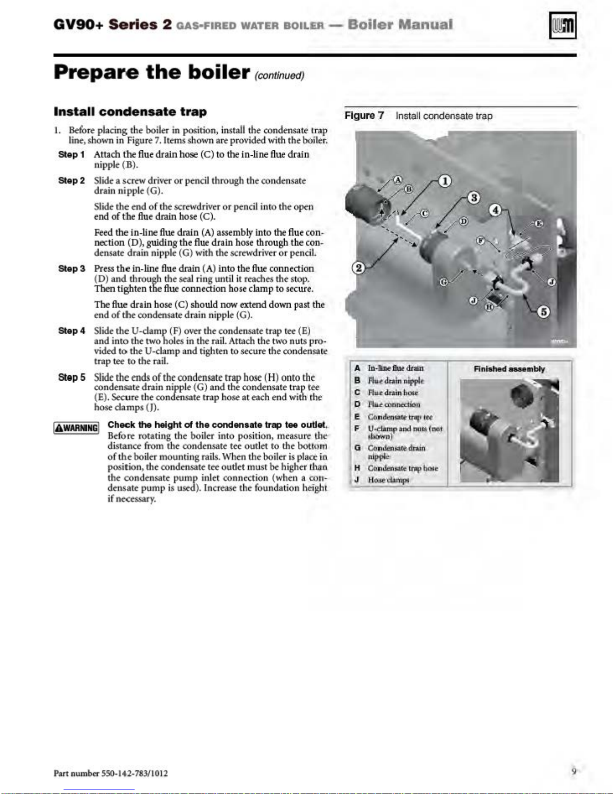
Slop 1 Attach the
Step
2 Slide a
Slop3
Slop4
Step
5
IA
WARNNG
in Figu
nip
ple
(B)
scTtW
dra
in nipp
Slide r.he end
end
of tibe
Feed
the in-line
nection (D), guiding the
densate
Press
the in-lin e
(D)
and
Then tighten tl ie
The
flue
end
of
tile condensate drain n
Slide t
he
and i
nt:o r.he
vided
tc>
trap
tee
Sl
ide
l'he
con
densa
(E). Secure the condensate trap hose at each end with
hose
damps
Choc:k
I
Before
distttnce from the con
of th.e boiler mounting ralls. When the boiler is place io
position, rhe condensate
the
condensa
densate p
if
nt<tSSary.
the
en
sate trap
the
boiler
re 7. Items shown are pr
flue
draJn h
.
driver or
le (G).
boiler
in
pos
'irton,
ose
(C) to the in-liue
prnc
iJ
install the
O\'
through
of r.he screwdri\'fr or ptnci l inro the
flu
dra
in nipple
thro
drain
U-cl
the U-
e draJn b
ugh
amp
two
ose
(C).
flue
drain
(A)
assembly
flue
drain
hose thro
(G)
with r.ht screwdriver or ptnciJ.
flu
e draJn (
the seal r
flue
bose
(C) sho
(F) over the condensate trap tee (E)
holes
damp
A)
into th e
ing
until it reaches
connection b
uld
now
ipp
in the rai
and
l.
righren ro sec
ose
extend
le (G).
Atrach the two nuts pro-
ro the raiL
ends
of
the
te drain n
tho
rotating the boil
ipp
le (G)
(J}.
holght
ump
o1
te
pump
is used). Increase the foundation hefghl
condensate
trap
and r.he condensate trap tee
th
o condonsato
er into
densate
tee
inler connection
hose
pos
t~ oud
outlet musr
(continvedJ
condensate. trap
ided wi
rh
the
flue
drain
the condensare
open
into
the
flue
ugh the con-
flue
connection
the
srop
damp to
ure
ition,
secure
down
past
the
condensate
(H)
on
to
trep , ..
me
asu~
~
ro the bottmn
be
higher Lban
(wh
en a con-
boiler.
con-
.
.
the
the
tht>
outlot,
lhf"'
Figure 7 Insta
A
lo-Outdnin
B
Au..e
draln
nfpplt
c
Flu.t
dni:n bose
'f1u.t
c:anne:.don
0
E Co
n.;Jcnsalf'
F
u~~ud ooL~
•b
-)
G
Con
nipPle
H Con
H~·
J
tnq
den~itt
dn.lri
denAuo
lnlf'
d.amp~
ll
condens<~
•
let
(oot,
hcl.l;e
l
e
trap
Fint.hed
MMtnbty
Part num
ber
550-
14-2
-783/10 12
9
Page 10
GV90+
Series
2
oAs·FIRED
WATER
BOILER
-
Bofler
ManuaJ
Prepare
Install high alti
when
1.
"IA"w"AR=
2.
3.
required
For installations at altitu
a. A special high altitude air pressure swirch
b.
The
gas
adjust~
IING
=~I
Failure
necessary>
or
gu
Obta
in the GV90+ hi
distributor. The hi
pressure switch.
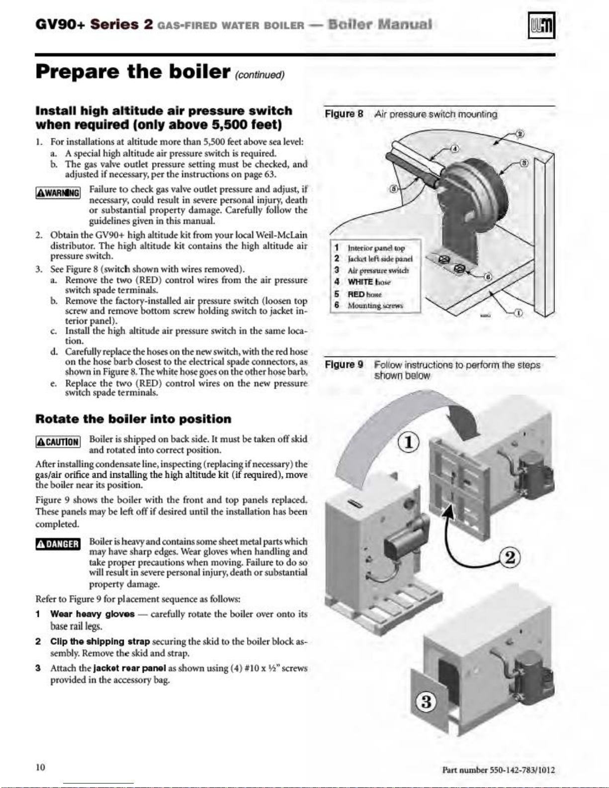
See
Figure 8
a. Remove the
swirch
spade
b. Remove r.he factory-installed air pressure switch (loosen rop
screw and remove bottom screw holding switch
tt'r'iO
r panel).
c. lnsraU r.he high alri
tion.
d. Cart full
on
$hown in
e.
Replace the
swarch
)• replace the
the hose barb cloStSt
spade te:rmi
the
tude
(only above
de more th
valve
outler
if necessar
substantial
idelin
(sw
Fig"~$.
y)
per the instrucrions
ro
check
couJd
proptrty
e$ given
gh
altitude kit from
gh
altitude kir contains the high altitude air
itch shown with wi
two
(REO)
te:rmi
nal
r.ude
hOStS
Th¢whi!¢
two (RED) cont
naJ
boiler
air
pressure
an
pressure
gas
result in
in this manual
seuing must
valve
oudet pr
St'\'ff't
damage. Carefully follow the
res
contro
l wires from the air pressure
S.SOO
removed}.
(continued)
switch
5,500
personal injur
)'Ou
feet)
feet
abo\re
i.s
r~uirM.
bt
checked,
on
page 63.
essure and adjust,
r l
oca
l Weii-
sea
s.
to
jad:er in-
air pressure switch in the same loca-
on rhe
new
switch. with the
to
the electrical spade connecrors. as
hQI¢g~on !h~
rol wires on
s.
o!'h~rh~bar\>,
r.he
new pressurt:
level:
y,
dearh
Mcta
rtd
and
if
in
hose
Figure 8
1 lntmtw
2
3 Air
4 WHrTEb
5 ReD-
8
Figure 9 Follow instruct
Air
pressure switch
poliJII!:I
COl?
J~1
ld1
sid~
panel
pres-
tuft'
!M"itcb
oilli-
MoUnlin.l-i.::r"""
shown
bgtow
moun~ng
ions
to perloon the steps
Rotate
!A
CAUTIO
After installing condensate line. inspecting (replacing
gas/alr orifice
the boll
Figu
re
These pantls may
completed.
the boi
N I Boileris shipp<d
and rora
and
t'r'
near its position.
9 shows
Bo
may have
rake pr
will
ted
Installing t
r.he
boiler with
bt
left
iler
i.s
h
ope
resuJt in
ler Into
eavy
sha
r precautions when mO\'ing. Failure
position
on
back side.lt must
inro correct position.
he
high allilude kit (
r.he
front and
off
if desir
ed
unr
il
rhe insrallarion h
and contain
rp edges.
St\'frt
s some sheet metal parts which
Wear giO\'fS
persona] in
jur
top
when h
y.
death
If
property damage.
Refer
to
Figure 9 for placement sequence
1 W
ear
hNYY gk>ves - cartfully roratt
base rail
2 Clip
sembly. Remove
3 Attach the )ack
pr
legs.
the
shipping strap securing the skid
O\<ided
in the accessory
th~
skid and strap.
tt
rtar
panel as shown using (4)
bag.
as foll
r.he
ows:
boiler over onto its
to
the boiler block as-
b<
taken
off
skid
if
necessary) r.he
required), m
panels replaced.
and
or
substanri
II
Ox
ove
as
bet-
ling and
to
do
S6
al
~»screws
n
10
P.an ntunber SS0-142-7M/1012
Page 11
GV90+
Series
2
oAs·FIRED
WATER
BOILER-
Boiler
Manual
Prepare
Perform
Pressure test boiler
no
ted
pro<t<ding.
IA
WARNING
Prepare
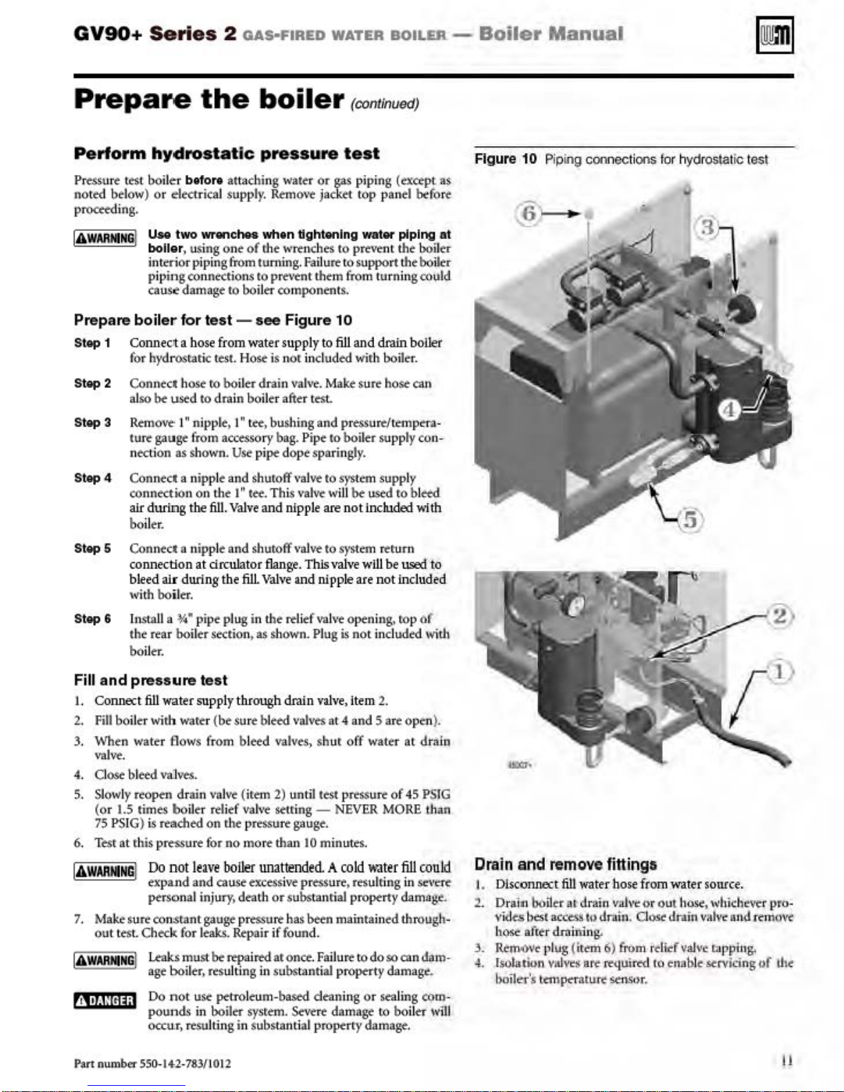
Stop 1 Connec>t a
Step 2
Step
3 Rtmo
Step
4 Connect a nipple and shuroff
hydrostat
bel
ow)
or electrical supply. Remo
Use
I
bollar, using
interior pipi
piping connections to prevent them from
caus.e
boiler
for h)rd
Connect
also
be
ture gauge
nection as shown.
connection on the 1"
alr dwilng tbe
the
befor•
two
wrenches
ng
damage
lor
test-see
bose
from water supply to
rosraric test.
h
ose
ro boil
used
to
dra
ve
I" nipple. I" tee, bushing
from
611. Valve
boiler.
boiler
ic
pressure
attaching water
ve
wh.en dghtenlng water piping
one
of
rhe wrenches
from turning.
to boiler
Fallu~
components.
Figure
or
gas
jacket
to
to
10
test
(continvedJ
fill
Hose
is nor included with boiler.
er dr
ain
vahre.
Mak
e sure hose can
in boiler after test
and
pressure/tempera-
accesso
ry bag. Pipe to boiler supply con-
Use
pipe do
tee
pe
sparin
gly.
valve
to system supply
.
This
val~
w
ill
be
and nipple are not
piping
top
panel before
preve
nt
support
turnin
aod
drain
used
included
(exctpl
the
ro bl
as
at
boil~r
the boi
ll"r
goo~.Jid
boiler
eed
"ith
Figure 10
Pip
ing connecli
ons
for
hydr
osta
lic l
esl
Step
5 Connect a nipple and shuroff
Step
c-Onnec.ti.on
bleed
wi
th boil
6 Insta
the rear boil
at
drc.ula
alr
during the
er.
ll
a
o/4
• pipe plug in
er section, as shown. Plug
boiler.
Fill and
I. Connect
2. Fill boiler wirh
3. ·
4.
5.
6.
IA
WARNNG
1.
I
AWARMNGI Leaks
t~j•Of!Hj;l
pressure
611
when
wate
\'lllve.
Close
bl
eed val
Slow
ly reopen drain val
(or
1.5
times boiJ
75 PSI G)
Tesr
Make sure
out test.
Ls
reached
at this pressure for no more than
I
Do
expa.nd
personal injur
co~rant
Check
age
Do
pounds
occur, r
test
water supply through drain v
wate
r (
be
r flows from bl
ves.
tr
rel
on
nolleave boiler
and cause excessi
gauge pressure has
fo
r l
eaks.
mu
st
be
boiler, resulting in substantial property damage .
not use
petrO
in boiler
esu
lting in substantial properr,• damage.
valve
to system rerum
tor
flange
. This
valve
will
fill
Valve
and nipple are not included
the
rtlitf
va
h·e opening. rop
is
not
alve
,ltem
sure bl
eed
valves
at 4 and 5 are op01).
eed
valves,
ve
(item
2)
ief valv
e setti
<he pressure
unattended. A co
y,
death or substanti
Repair if
rtpa
ired aronce.
leum-based deaning or sealing
sysrem.
shur off water at
until test pressure of 45
ng-
NEVER
gauge.
10
minutes.
ld
ve
pressure, resulting in
al
property
been
maintained through-
found.
Failure
t:odoso
Severe
damage
be
1.lSled
incl
uded
2.
MORE
ll~ler
fill
dama.g
can
to
boila
to
of
wi
th
dta
ln
PSIG
than
rould
Si!\'t're
e.
dam·
CQm
wm
-
Drain
2. Dr
3.
4..
and
remo
1.
Disconne.:.t
al11 bobt:r
vidt.s
best
access
h~
after
cl.rnining..
Rto:m
JI)\'e l'lug {itmi
lso
la.tion
viti
boiler's temp«ature
ve fittingo
fi1l
water
hose
at drain vahll:
to dmln.
6)
from rditfvalve
\'ell: at<"
m.Luif'C!'d
Sc.'nSor.
from
water source.
or
out
hose, w
dost
drain
valve
rappU\8;
10 enable servicing
hic
hever pro-
tu
ld reJnovt
uf
th(
Part num
ber
550-14-2-783/1012
11
Page 12
GV90+ Series
2
oAs·FIRED
WATER
BOILER
-
Boiler
ManuaJ
Install
water
Use two wrenches when tightening water piping
boller, using one
interior
piping
cause damage to boiler component:s.
The
be
to
This is
ci
cuJators.
i
piping
ronntction.s
cast
iron
kept
al
or
prevtn.t possib
done
rculators.
Fa
njury,
death or substanti
General piping I
Minimum
Figure
Additional
Follow
ASME
llmtt
standards
lnsta
and
\\fi
rro
Set
limit conrrol
pipe
siz:e
11
Provide
below (based on 20'F tempera
GV90+ 3 or 4
GV90+ 6 or 6
ing standard industry pracri
or Canadian
may
be
to determine·
JJ
a manual r
th
e isolation
re
the manual
l.
the manual r
boi
Boiler
limit
net<led. Consult locaJ
loop
controls
r
equir~men
if
e-set
valve.
reset
es-et limit control at least
St-rting
piping
of r.he wrenches
from
turning.
to
pre\re
heat exchanger r
above 1
DO
llu
nform
for
ler loop piping no smaller lhan li
needed.
high temperature limit
(maximum setring
4WF during
ility of
corrosion
auromaticall
NOT
~
ro comply could result in
boiler
pipe
limit in series with the boil
y, using the boiler's
rtmove
al
ati
on
loop
size,
ces.
if installation
ts,
an
additio
r~ui
Wir~
as
to
prevent
Failure
ro support the boiler
nt
them from turning could
eturn
temperature
all
times
due
to condensatio
or
ramprr
prope-rty
with these cir-
k\'t'rt
damage.
piping
ture ri
se)
Minimum
1"
i.s
to comply wi
nal
high temperature
remen
ts
for other
shown in Figure 67. page 56.
between
er limit con·
200F
above the boiler
2200F).
the
of
optrarion
interna
pe-rSOnal
sted
the boiler
at
boiler
mu.s~
n.
th
codes/
Air
separator
lnst•ll
ali
air N)>lrator
rnanua
l.
Fur
.single-1.onc--
in
Lht-
rrlllrn piping
aiJ.ows
m01,11lting
off
of
the
In
st a
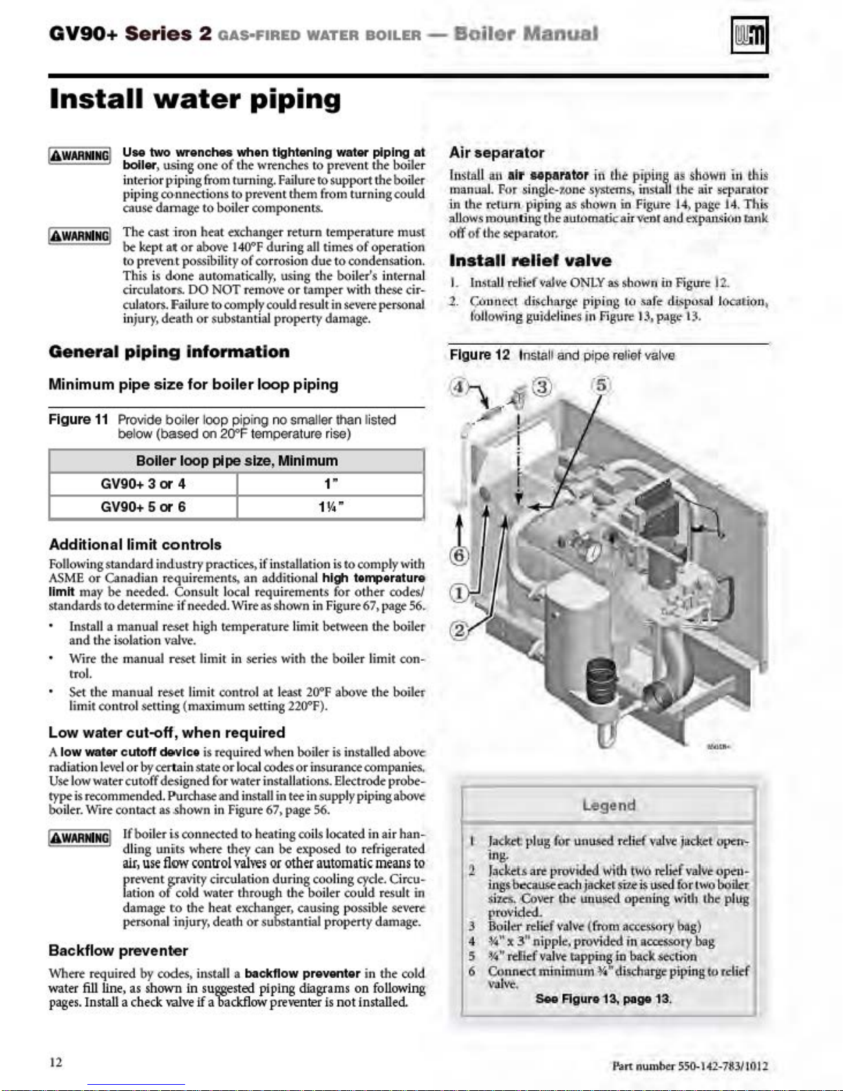
ll reli
l
L
ln.stalJ
1. Connect discharge pip ing 10 safe di
tb
llow'i
r.be
s<poararor
ef valv
t<litf
val""
ng
guiddblt<-$
Figure 12 Install
(
4}~,.\i
.. ,
..
j®
,.....
" r
.syskr
a&-
:shown
aut.omatic
.
ONLY
in
and
pipe
in
tli<
e
as sbown in Figut.
Figure
relief
j·
r
'
pipi.ng
ns..
in
ait
as
install the
Figi,Jrt
J4> page 1
Vtor and
..
~pus·aJ
1$,
pt.~g-e-13
valve
shown
!Ur
dpatts
12.
.
ir1
th
is
-separator
4.
This
i(,o
tank
IOGition
•
Low
wa1er
A low water cutoff
radiation l
Use
low
type is rtcommended.
boiler. \"'ire contact as
cut-off, when required
dcwlc•
e-.-e
l or
by
~tain
wate
r cutoff designed for water instaJJations. Electrode probe-
If boil
er
units where they can
dling
air , u
se
pr~\rt
nt
Jation
of
damage
personal injury. dearh or substantial property damage.
is required when boil
stat~
or local codes or
Pur
chase and i
.shown
i.s
connected
in
Figur~
nstall
in tee in supply
67. page 56.
to
heating roil
be
fl
ow
control
gravity circulation during cooling cyde. Circu·
cold
r:o
the hear exchanger, causing possible
\'lllws
wat~r
through the boil
or other
Backflow prevent<!"
\"/here required by codes. install a backflow preventer in the cold
water
fill
pages. Install
Une, as
t2
a c.
shown
beck
\'alve
in
s
uggested
if
a
backflow
piping
pre't<enter
er
is insralled above
i
nsuranc~
s located in air han-
exposed
companies.
piping~
to
refrigerated
automatic
er coul
d r
diagram
s on fo
is not installed
mean
esuJt
seveTe
llowing
s to
in
Legend
)atlo.-t plug
lng.
2
fad<tls
i.n
gtb.:c:au.~racl
$ius.
alt.
proVIded
-C/J\'<r
fclr
unused rcllef V'
1
jad:et
the
unu>«i optnln
rn:rvtclt<L
3 Boil
4
5
6 Connect
er
relid' \'liiV< (from ll«c$$Ory bag)
'4"
x 3
••
nippl~.
provided in
~··
fditf
vah't tapping in back
\'31\'C,
min1mw'n1i,.
S..
flgur•1
oli\'
t
Jackt
W!U
r t
W6
re
lief
valVe
$'iU:
i
ti,I;Sed
for two bOtltr
.g
Wid>
acccssory-bag
.$b:ti<>n
c,l.ilicharg'e
3,
pogoo
r..art
plp.
ing
13
.
nwuber SSO-l42-7iU/IOil
.....
"~"''"'
op6i-
the
plug
to
rdid'
Page 13
GV90+ Series
2
OAS·FIRED
WATER BOILER -
Boiler
Manual
Install
Figure
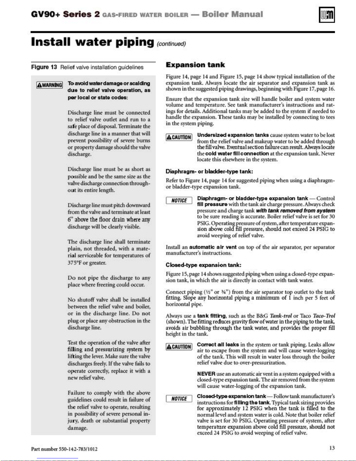
13 Relief valve installation guidelines
IAwARNIN61
To avoid
du•
per
Discharge line
ro rtli
safe place
discharge li
p~•ttn
or proptrty
disdlarge.
Dischar
po
\~vt
out its entire l
Discharge
f'rom
6'
discharge
The
plai
rial
37
Do not
place where
No
betweton r.he relief valw and boiler.
or in the discharge line. Do n
plug or pl
discharge line.
fur
filling and pressurizing
l
disdlarges flffly. If !he
Optne-w
Failure
guidelin
r.htin possib
jury, dear.h
da.mage.
water
w.-rd•m•ge
to relief VIIYe
loc•l
or st.te
ef
valve
of
disposaL Terminate the
nt
t
possibiliry
damage should r.he
ge
line
ssible
and
discharge connecti
line must pitch downward
the
valve
above
the
will
discharge line shall terminate
n,
nor thread
se
rviceable for temperatur
5°F
Or grt:ater.
pi
pt
(reezing could occur.
shuroft' valve sha
ace
the operati
ift
ing r.he le•;er. Make sure r.he
piping
or
op•mlon,
codM-
:
must
be
con
outlet
and
in a manner
of severt bums
must
be
as
be r.he
same sir.e
on r.hrough-
engr.
h.
and tenninart
floor
drain
bt
dearly
vis
ed,
with a mare-
the discharge ro
ll
be
any obstruction in the
on
or r.he \'al
vah'f fail
rate corr
rf'lief vah·
rf'liei'
ectly,
repl
ace
e.
to
comply with
es could resu
\•alw
ili
ty
of
or subsrantial property
lt
in failure or
to
optnate. resultin
se\·e:re person
acalclng
nected
run ro a
that
\'ll]vt
short
as
at least
where
ibl
e.
es
insralled
ve
after
system
valve
it with a
r.he
above
al
• •
will
as
the
any
o(
any
ot
by
s to
g
in-
(continued)
E
xpansion tank
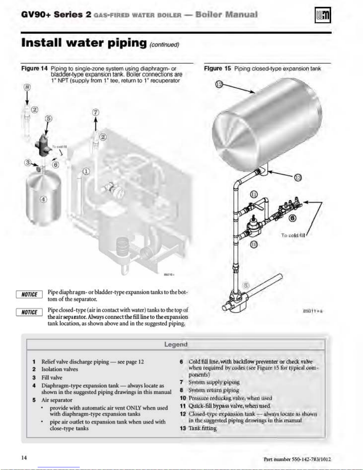
Figure 14. page 14 and Figure 15. page 14 show typical insrallation
expansion tank. Al
shown in r.he suggested piping drawings. beginning wi
Ensure r.hat the expanslon tank
volume
ngs for detai
i
handle
in
and temperatu-re.
th
e expansion. These
r.
he system pipin
Diaphragm·
Refer
ro Figure
or
bladder-type
NOnCE
ll
an
Insta
manufacturtr
automatk
way$
locate r.he air separator and expansion tank
size
w
iJI
handle boil
Set'
tank manufacturer's instructions and rat-
ls.
Add
iri
onal ta
nks
may
be
added to the
ranks may
g.
UndeniZCid
from
th
the
fiU\•ah-e.
th
ecokt
locate this elsewhere in the system.
or
blaclcler-type tank:
14
,
page
expansion tanks cause system
e r.tli
ef
\'lllve
E\'entual
water
flllconntcUon at the expansion tank.
·14 for suggest
be
installed
and makeup water to
section
fallucecan
ed
piping when using a diaphragm-
expansion tank.
Diaphragm·
flU
prNSU'e
pressure
to
be
sure r
PSI G.
Operating pressure
sion abo\
avo
id weeping of relief vah·e.
's
instructions.
o.-
wi
a~nd
char
e:ad
ing
-e
cold
air
wnt
bladdor·typt expansion tank- Control
th th
e rank air char
ge
tank
with
tank
is
accurate. Boiler reli
of
fill
on
pressure
system. after temperaturt
, should not
top
of the air separator, per separator
th
Figure 17, page
er and system water
sysrem
by connecting
be
resul
ge
pressure. Always ched::
removed
ef
\oalve
exceed
Closed-type expansion tank:
Figure IS, page 14 shows suggested piping
sion tank, in which the air is dirtctly in contact with rank
Connect piping
fitting.
Slope
hori1..0nra
Always
(
a>'oids
heighr in the tank.
shown
NO
TICE
use a
). The
air bubbling
(Y:t,.
or ·W') from
any
horizontal
l pipe.
tank
fitting. such
fittlng
reduc
the
COI'I"eCt
air ro escape from the system and
of
th
e tank. This will
rdiefval
NEVER
dosed-type-expansion rank. The air
will
Cl~type
instructio-ns for
for
normal level and system water
va
t
ern
excttd
v.e
use
cause water-l
appr<>Ximately
lw
i.s
se
peca
ture expansion
24 PSIG
piping a minimum
as the
es grav
ity
<>Ugh
the
tank wate
aU
leaks in
due ro over-prtssuri:zarion.
an
automatic a
oggi
expansion tank-
ftUk'lg
12
·t for 30
PSJG.
to
a\ro
when
usingadosed-typeexpan-
the
air separaror t
of t
B&G
Tnnk-trol or Taco
flo
w of wate
the
system
result in water loss
ir
ng
of
the
PSIG
Operating pressu
abo\'e
id wetping
r In
r, and
provides
or
tank piping.
will
venr
in asysttm equipped wi
~moved
the expansion tank.
Follow
tank. Typical tank
when
the
i.s
co
ld. Note that boiler relitf
cold
fill
of
reli
op
outlet ro r.he tank
inch
the
plplng
cause water-logging
r.hrough the boiler
tank
tank
re
presSW"e
ef
vahre.
of
the
as
16.
if needed ro
r.o
tees
ware
r robe l
os
added through
t.
Always
locate
Never
from
sy.tem
is
ser for 30
expan
24
PSIG
to
warer.
per 5 feet of
Taco-Tro
to the
tank,
the
proper
fill
le:aks
alloo.v-
th
from rhesystem
man
ufac[Uru's
si'z:
ing provides
is
fill
ed to
the
of
sysrem. after
, should
not
t
-
l
a
Part num
ber 550-
14-2
-783/10 12
13
Page 14
GV90+
Series
2
OAs-t'IRED
WATER BOILER -
Boil
er ManuaJ
Install
Figure
14
Pip
bladdllf•lype
1" N
water
ing to single-zone system using diaphr
expansio
PT (su
ppty from
piping
n tank.
1"tee, return to 1
Boiloc conn
(cononuedJ
"'
recuperator
®
t
agm
ectio
· or
ns
are
Figur
e 15 Pi
ping
closed-type expansion
lan
k
Pipe
NOnCE
NO
nCE
diaphragm-or
tom
of
the
Pipe dosed-
separator.
type
theairseparat
tank IOC'<ltion, as shown abc
1
Rtli
ef
vah·e discharge piping-
2
Isolation
3 F
iJI
4 Di
s
how
5 Air separator
t4
\<al\'d
valve
aphragm-type
n in the suggesttd pipi
provide with
with
diaphrngm
pi
pe air oudet to
dOS<-I)'pe
UUlk.s
bladder·l)'peexp
(air
in
contact with
or.
Alv.a
ys
connect
we and
stt- page t 2
txpanston
automatic air wnr ONLY
-typt expansion
expans
tank-
ng
drawings
ion
rank
ansion rank.s
water)
the
fill
line
in
the
al
ways
in this
when
ranks
when used
to
tank.s
to
to
the
ex
suggested
Legend
locate
as
manual
used
wi
th
the
bo
t·
the
top of
pan
sion
piping
l
8 Cold
7 S'r•l=
8 $ys\o:m
10 PfclsWe
11
12.
13 Tank fittlng
Jill
line.With
wb,..
rtquited
pi\lll'lit
~)
.u~plyp
n;wro
i'edllcing valVe
Quk-k>Jill
C
IU<M-
i
ll
the
b)'lll>ss
cyl"'
:~
ugg
esctd
.bac~owpteventerilr
by
c<ld•• t<et Figute
iuin
piping
valve, wbel) u
E'ltj>I'>Ml6o
piphl8
$
wh.m
1
ranlt-
d.rawiqp
15
USc~
sed
alw
oys
iu
thi5
Ch
eck valve
foi
typioil cOm-
!o.:a~e
o.<
Slwwu
manua
l
Page 15
GV90+ Series
2 OAS·FIRED WATER BOILER -
Boiler
Manual
Install
Syste m
NOTICE
Ci
rculato
IAWARNING
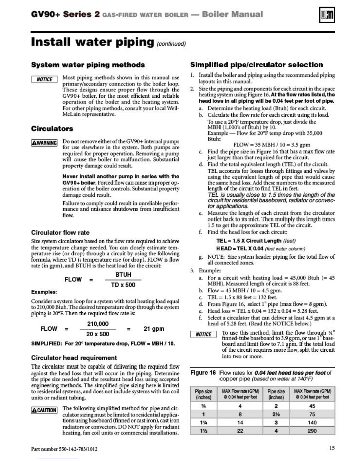
Circulator flow
Size
r.
he temperature change needtd.
perature rise
formula, where
rate (in gpm). and
I
system c.irculators based
water
wa
te r piping me
Most piping
primary/seco n
These
GV90+ boiler , for the
oprration
For othe
McLain r
rs
Do
no
for
u.st elsewhere in
rtqu-irtd
w
ill
cause the
pr
operty
Ntver
GV90+
erarioon
damage
Failure
maJKe
flo
w.
(o r
drop
TD
BTUH
methods
dary
designs
of
the boiler
r piping
tprtktltath
t remove either
for pr
ope
boiler
damage
Install
another
bollcw. Forced
of
rhe boiler controls. Substantial pr
could
rtsult.
to
comply coul
and
nuisance shutdowns from insuffident
rate
on
} throu
is
temperature rue (o r drop),
is the hear load
FLOW =
Examplu
Consi
to
210,000
piping
:
der a sys
Btuh. Tbe
is
20'F.
tem loop for a system with
desir<d
temperature
Then
the required
210,000
FLOW =
20x
SIMPUREO:
Circulator
Th
e circulator
against the head Loss that
r.
he pipe si
engineering
ro residential systems.
units
or
I
AcAumN
For
20"
IOJTC)oraturo
head
te
needed and r.he resultant head loss using accepted
method
radia
nt
The following sim
I
cuJaror
tionsusingbaseboard (finned
r
heati ng.
requirement
mUISt
be
s. The slmp
and does n
tub
ing.
si:z:
adiatOrS
f.m
capable of delivering the
will
ing must
or
COn\rtctors.
coil uni
piping
thod
shown
con
ensure proper flow through the
methods>
•e.
of
the
r operation. Remo\•ing a
to
cou
ld result.
flow
d result
the
flow
You
gh
a circuit by using rhe foll
in th
necti
on
to
mo
st
effkient
and Lhe
consult your local Well-
the
GV90+ intern
system. Both
malfunction. Subsrantial
pump
In
can
cause
in unre-liab
rate required
can closely estimate
fo
r the circuit:
(continued)
s
i.s
manual u.se
the boil
and
heating
pumps
..
-.
improper
to
FLOW u flo
er l
oop
reliable
syst
em.
al
pumps
pump
wtth
ope-
le
~rfo
ac.b..ieve
tem
owi
art
the
op-
rry
r
ng
w
BTUH
TD
X 600
rot:al
heating load equal
drop
through the system
flow
rate
is:
21
600
occur
llfied
ot
pUfied
be limited ro residential applica
rs
=
drop,
FLOW • MBH
in
the piping. Dt-termi
pipe
~z.ing
include systems with
method for pipe
or
DO NOT apply for radtant
or commercial installations.
gpm
/10.
required
here is limited
cast iron), cast iron
fan
and
flow
ne
coil
cir-
Simplifie d
t.
lnsrall r.hr boiler and piping usi
.
-
-
layou
2.
Site r.he
heating system
head
a. Dettrmi
b. Calc.ulate the
To
MBH (I
Exampl
Btuh:
c.
Find the pipe site in Figure I 6 that has a
just larger than thar
d. Find
TEL
using the equivalent length
the same head
length of the circuit
TEL
circuit for residential baseboard, radiator
t
e.
Measure-r.he ltngth
oudet
1
f. Find r.he head loss for each circuit:
g.
NOTE.:
aU connected
3.
Example:
a.
Fo
MBH).
b. Flow= 45 MBH / 10 = 4.5 gpm.
c.
TEL=
d. From Figure 16, seifct I" pipe (max
e. Head loss = T
f. Selecr a circu l
head
NOnCE
Figure 16 Flow ra t
Pipe
size
(lnctoas)
~
1 8
1
14
11\
pip
e/c
ircul
rs
in
r.his
manual.
pip
ing and compontn
usi
ng
Figure-
1
IOOoSin
or
..5
all
piping
wtll
nt
r.he
heating load (Btuh) for each circuit.
flow
rate f
use a
200F
temperatu
,OOO's
ofBt
uh) by 10.
e-Flow for 20'F temp dr
FLOW=
r.
he
t:Otal
accounts
Is
usually_
35
required for the circuit.
equh
·alentlengr.h
for
losse
loss.
Add
to
close to
applicstions.
of
bsdc
to irs
inl
et. Then muldpl)• this length
to
ger
tht
approximate
TEL • 1.5
H
EAO •
X Circuit
TEL
X 0.04 (feet
Siu
sy
stem """der piping for the total
or
re
MBH I 10
s through 6ttin(!'
tllese numbers ro rhe
find
each circuit from rhe circulator
Length
z.ones.
r a circuir with heating l
Measur<d
1.
5 x 88
of
5.28
To use this method, limit the
finned-tube baseboard
board
the c.
of
into
<:Opper pi
MAX--
• 0
.04
I
length
feet = 132
EL
x 0.04 =
ato
r that can deliver ar least 4.5 gpm at a
fee
L (Read the NOTICE below.)
and
limit
irc.uit
cwo
or mort .
es
...
4 2 45
14 3 140
22
flo
requires more
tor
0.04
pe
(based
(G
Pt.l)
per
loot
ator sel
ng
the recommended piping
rs
for each circuit in rhe space
6.
At
the
bo 0.041oot
each
drc.uit using its
drop, just divide rhe
of
TEL
1.5
times the length
TEL
of
wate<
oad=
of circuit
fe.t.
132
x 0.04 = 5.28 fe.t.
to
3.9 gpm,or
w to 7.1 gpm.
fMt
hfHid Joss,.,-foot of
oo
water
Pipe
size
(l
nctoas)
:lli
•
ect
flow
rates lsted,
per
op
with 35,000
= 3.5 gpm
(TE
L)
oftht
pipe
r.hat
in
feet
.
the circuit.
(feet)
column)
45,000 Btuh
is
88
fffi.
flo
w= 8 gpm).
flow
If
flow
, split the drc.uit
at 140"F)
MAX--
• 0
ion
foot
of
max
flow
circuit.
and
valv es
would cause
measu~d
or
convec·
tbrou3:h l4"
use
the total load
.04
...
per
75
290
the
piP<>-
load
rate
by
of
the
times
flow
of
(=
45
I base-
(G
Pt.l)
loot
Part num
ber 550-
1+2-783/1012
15
Page 16
Page 17
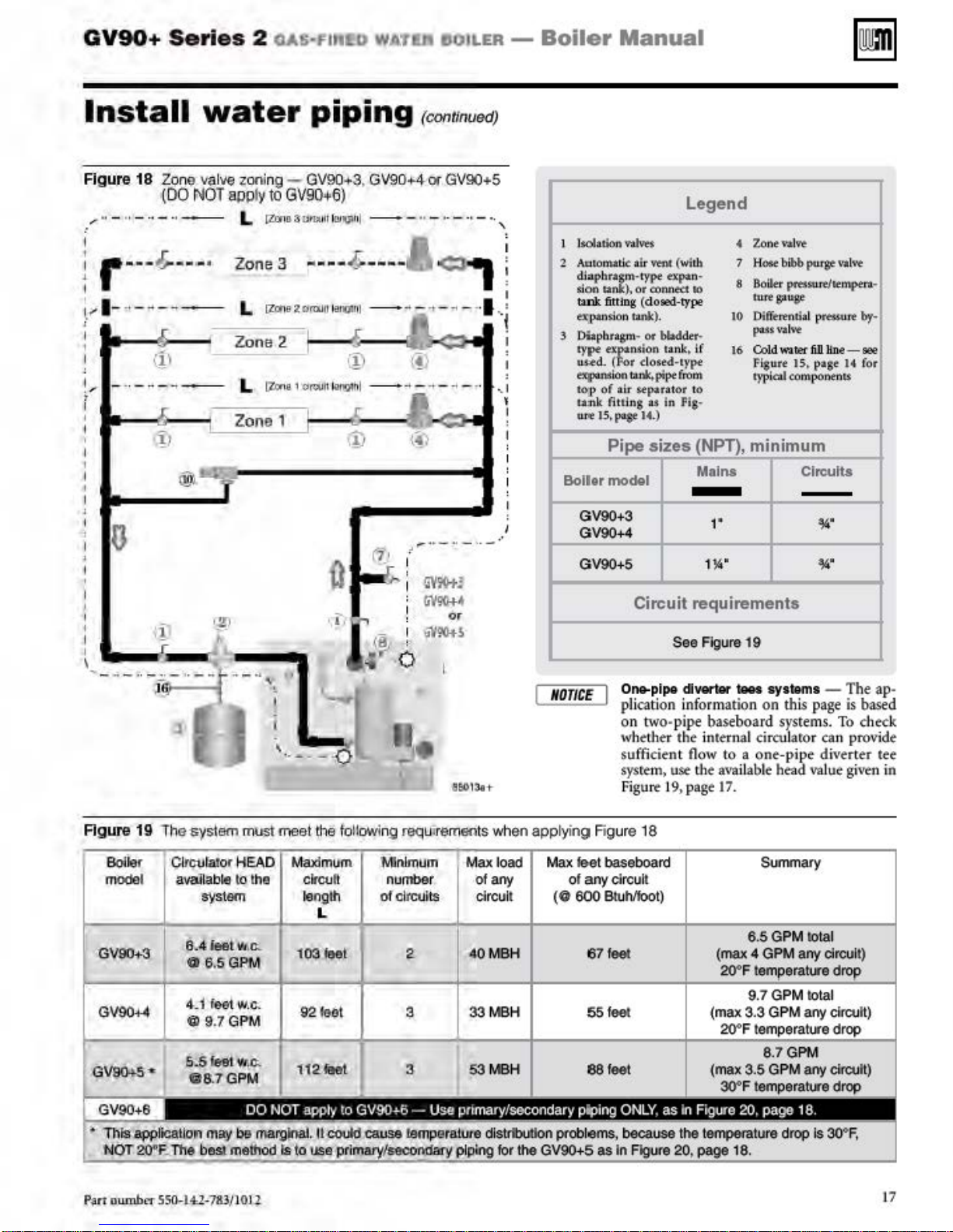
GV90+
Series
2
o.Ali-FIIIW
WATia
IIOILER -
Boiler
Manual
Install
Figure 18
, ··-··- --··-
I
1
r---
\
...
1-,
'
I
'
I
Zqn~
(DO NOT apply
~
-"-
water
vallle
zoni
L
---
--
®~
Zone 3
·
L
Zone 2 1
L
Zo
~
piping
ng -
GV90
+3, GV90+4
to
GV90
+6)
(ZiY
10 3U•t•u
li
~
.liVI
h
l
- - " - •· - ·• - •·
----
~
----
lZCfle
2
Clrctl
!l
P-!Vlfll -
~Zona1o-rWfl~&ml
ne
1
_ .. -
(contrnued)
or
GV90 +5
~
..
-
'"l -...
..
- .. - ·· ._,
- • • I
-------------4
....
..
_,- ·-
ff_t
'
'
I
~
I
..
i
I
I
I Isolation 'ildvet
Aolomalk
2
di
aphr~m-typt ~n
lion u ). or conn«:t
ta.nk
ex;
DUpbra&m·
ty~
'
uud.
~ion
to~p
u:nk fiu.ins u in Fi
UJ'It
Boll or
GV90+3
GV90+4
GV90+5
air
'lftlt
6tuog (doted-rype
pantion tank). 10
or
af:n
( r
of
15
, f!t8t 14.)
Pipe
model
bbddtr-
sion tllnk,
dosed·typt
tl.nk.pipefrom
a.tr
upua
sizes
tor to
Legend
Zonewlft
(with
•
7
Hose
-
10
if
16 Cold
s·
(NPT),
Mains Circuits
1'
1l4'
bibb
8
Boile
r
prtsswt/~tmptn.·
"""8'"8'
Difft:rentia
putva
lw
watet
Fisure IS, page U for
typicd componen
minimum
pu.rse
l
pttsswt
fi.D
line-
14'
14'
va
lw
br·
8t'lt'!
tt
I
•
I •.:fl
: :
'
~
-
!_
--
-
-
--~
~
F
1
f
Figure 19
Bo<ief
mode
t3V90+3
GV90+4
1hesyslam
Ql
rculalor HEAD
l avallabls
S\'SlO<Il
e,
.o
~eot
0 6.SGPM
4-
.1 feet w.
Ill 9.7GPM
-
---
m
~
10
the clr
""
"'
c.
meet lhe tollowing r
Maldmum
cutt
longll\
L
103 lt!el
92feo
'M1nlmum
number of any of
oto
l 3
equ
irem6f"lts
lrcults circuit
when
load
40MBH
33MB
NOTICE
applyin~;~
Max
(0
H
Circuit
One-p
plication information
on two-
\vhethe:r the internal circuJaror
suff'ic
sys
rem> use
Figure 19, page 17.
Figure 18
f&el baseboard Summary
any
circuit
600
BWMoot)
67
feel (max 4 GPM any circuli)
55
feel (max
requirements
See
Flgure19
lpo
<1
- - systoms
pipe
baseboard
ient
flow
the a\'llilable head value given in
to a one
6.5 GPM
20'F
9.
3.3
on
this
sys
tems.
-pipe div
1018
7 GPM
1018
GPM any clrcuh)
-T
page
can
1
1
he
is
based
To
check
provide
erter
ap
tee
-
5.5
,
QV9(H.S•
f,ln
number S50-l4:l-783/ l 011
loti! "'""
08.7GPM
f1~lilat
3 53 MBH
eo
feel (max
30'F
6.7GPM
3.5
GPM any circuit)
drop
17
Page 18
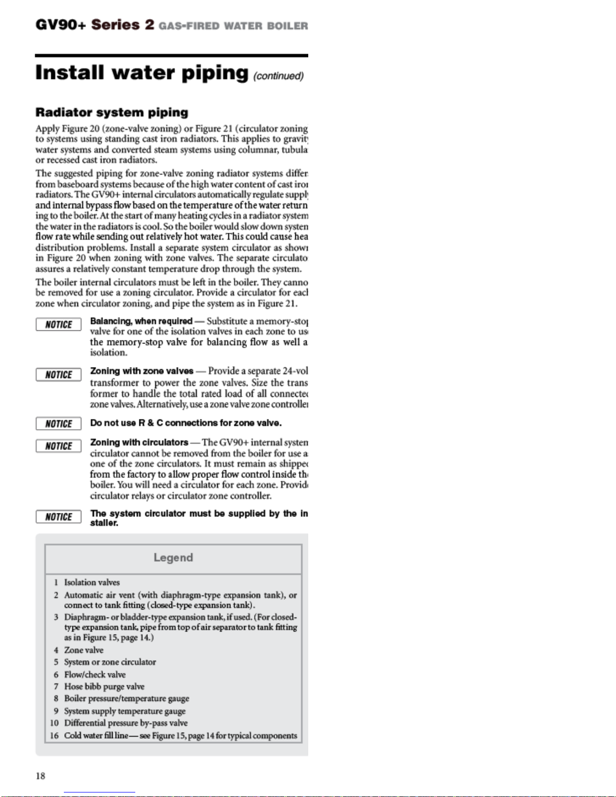
Page 19
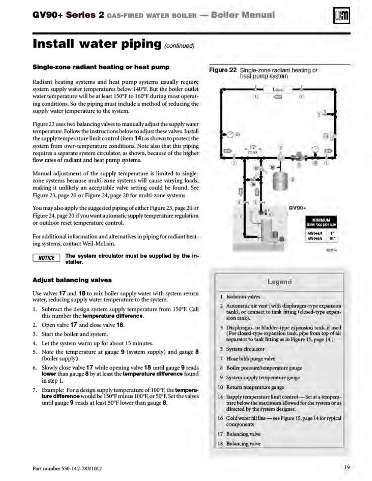
GV90+
Series
2
oAs·FIRED
WATER
BOILER
-
BaUer
Manual
Install
Sin
gle
-zo
Rad i
anr
heating
system supply
water temperarure
ing conditions.
supply water temperature
Figure
22
uses
rtmperaturt.
the suppt) • temperature limit control (irtm 14)
sys
tem from over-temperature conditions. Nore also that this piping
requires a separate system circulator,
fl
ow rat
es
of radlant and beat pump
Manual adjustment
zone systems because multi-zone sysrems
making it unlikely an acceprable
Figure
23,
page
You
may also apply the suggested piping
Fig
ure
24,
page
or outd
oor
reset
water
ne
rad
'-11 healing or
sys
tems
and
war:er
temperatures below
will
be
at least I
So
the piping must indude a method
to
rhe system.
two
'balancing val
Follow
the instructions
piping
heat
pump
SOOF
ves
lO
manually adjust
~low
as
system
of
the supply
20
or Figure
20
if
you wanr auromatic suppl
remptraturt
temperat
valve
24,
page 20 for multi-
contro
l.
(continued)
heal pump
systems usuaHy require.
1400F.
But
the boiler
to
1600F
dur
ing most opt.rot-
of
r
Mudng
rht
supply Wiiltr-
to adjust these valvts. huuU
as
shown to protect tht-
shown>
because
of
the hjgh
s.
u
~
is limited
will
cause
setting could
1.o
of
eir.her Figu
)•
temptralure regulation
to
varying !
be
found.
ne systems.
re
23>
page 20 or-
Ol,it.leL
the-
n-
single-
(load$.,
See-
Figure
22 Sin
h
jo
g!e.·zo
eat
na
PUII\P
"'
radi~t
heating
systom
"
01/90+
ot'
or
a
""'
.,-,
For additional information and altemativts in piping for radiant
ingsystems> con
J
/IOTIC
E 1 Tho system circulator
Adju
st
Use
\•alves
water, reducing su.pply
I. Subrract the design
rhis
number rbe temperature
2. Open val
3. Starr the
4. Let the sysrem warm up
5.
Note
(boiler supply).
6.
Slow
ly
tower th
in
~t<p
1. Example:
ture dtfferenc.e
until gauge 9 reads at least
tad.
\Veil-Mcla
stall«.
bal
anc
ing valv
17
and. 18
to
ware
system
v<
17 and
boiler and
the temper
dose
an
gauge 8 by ar least the
I.
Fo
do,.
system.
atu
re ar gauge 9 (sysrem supply) and gauge 8
\-alve
17 while opening
r a desi
gn
woUld
in.
,...,t
bo
supplied
es
mix boiler supply water with
r temperarure ro the sysrem.
supply rempe:rature from 1
va
l\·< 18
f'o
r about
supply
be
I
SOOF
SOOF
dtffennce
.
temperature
temperatu~
minus
lower than gauge 8.
15
minutes.
\•alvt
IOOOF
.
18 unr
of
1 00°f,
. or
dtfferenc•
SOOF. Set the
by
sys
tem return
50°F. CaU
ll
gauge 9
r.
he tempera-
hc:a
tho
In·
1't'"Jd
fOund
vn.J\ftl
t-
"'""
Lege11d
1 Isolation
2 A·utomaric air vrnt twilh
tank.),
s.ioncank
3
~i.ap.h.rayn·
(F'ordasti!·t)~expan·
sep~.mtort
5 S)?tt:m cirtu:b.tor
7 H
!
fl
IRHierr
~
Systt:m
10
R~tu.rn.
14
~
Upplyfempt:ramr~
tu
directed by the-n•stt m
16 Col
compa.n~nn
17
Ril..l
T&h'el.
or
oonnec
uo
diapfU'BJPll
tank ,fitting
l~
or
bl
adthec-typ
o
tarik 6ttingasiittf.lgurt
nSt" bibb
rtbtklw th¢
purg.e:Ya.h-e
~e(te:mpc-rarure
supPl~
terupen1twl! g:.uge
rem
pt:rof\l.fepu~
max
imum
dwar;er 6Uline-
ando_g
vai"Vt>.
t:
sion
tank.
gauge-
Umitconttoi-Sd:'!lt'9
'Ill~
Wig:ner
seef
igure
·fl'F't
d-type .
p¢
fm.rn
15~
the
apauSioll
e:xpa
t¢k
i.
(l.!Sed
1
topofilir
pagt 14.)
U!mpe:ra-
'Ylll<!'m
forrypfca
or Ill
(dose
exF*~.Oo
pi
for
.
ts~pagelA
n·
I
l
Part
number
550-1+2-783/1012
'!
S.l""""g""'="'
!:.----------.!
19
Page 20
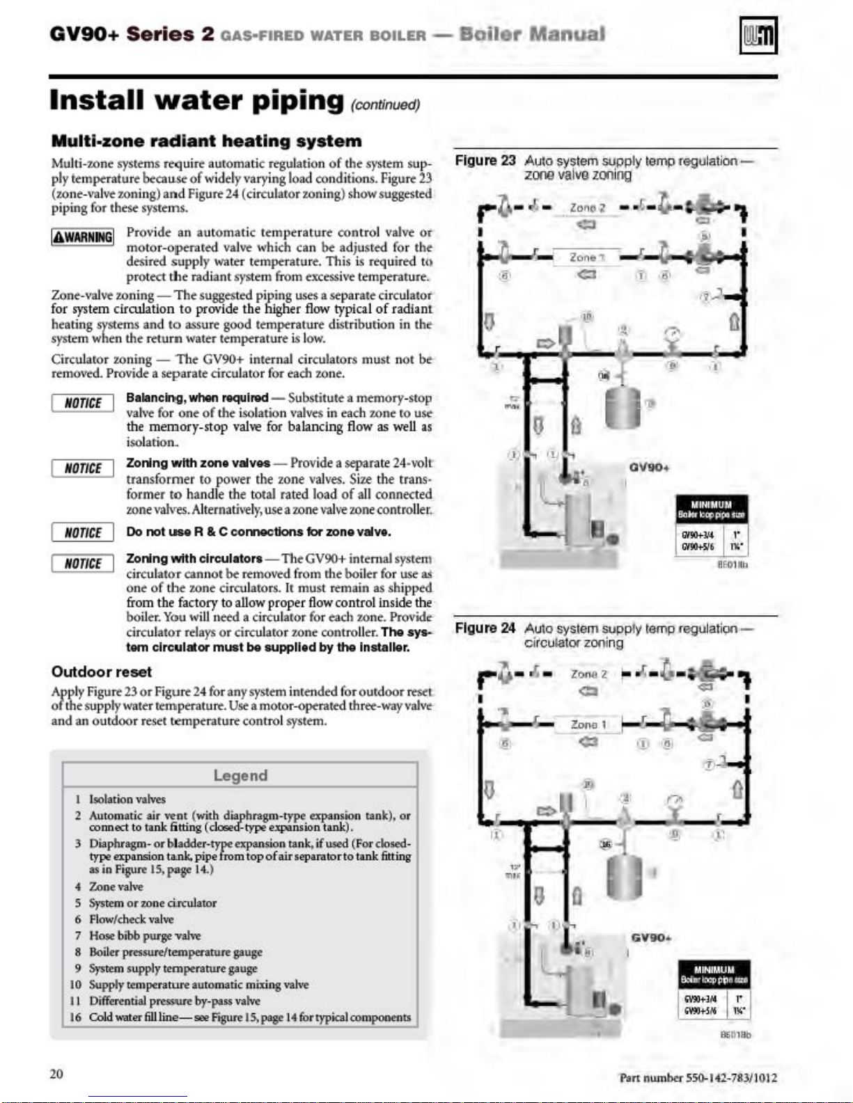
GV90+
Series
2
oAs·FIRED
WATER
BOILER
-
Boiler
ManuaJ
Install
Multi-zone
Mu
lti-zone systems require
ply
temperature
(zone-
\-alve
piping for these sysrtms.
I
AWARNJfG
Zone-valve
for
heating S)'Sttms and
system
Circul
remo,red. Provide a
I
NOTICE
NOTICE
NOTICE
I Provide an automat
sys
tem
whe
.aror zoning - The
water
radiant
becau.se
roning)
zoning-
circulation to
n
and
moto
r-Optr.ued val
desired
protect the radi
supp
The
to
the
rttu
rn water temperature
separat~
Baianc
lr).g,
val\·~
for one
the memory-stop v
isolarion_
Zoning wtth
transf
orme
former
zone
Do
to
vahres.
not
LIM R & C
piping
heating
auromatic regulation
of
wi
dely
varying
Figure 24 ( circularor zoning) show suggestfil
ic
ve
l)• water t
sugge
provide
assure good temperature
GV90+
circul
when
of
zon•
r to power the zone
hand
Alternath<ely,
tmptratu
ant
system from
sted piping uses a separate circulatot
the
internal circulatorS must n
atO
*"'lnKI
the
isolation
ah-e
valves- Provide a separate 24-voiL
le
the
total
coi'WMtCdons
system
load conditions.
temperature control valve
\vhich can
rt . This is required tn
excessive
hlgh
er
flow
is
l
ow.
r for each
- Substitute a memory-stop
valves
for
balanc.ing
valves.
rated
use
a 20ne
for
rconunuedJ
of
the
be
adjusred
temperarure.
typical
di.srri
buri
7.0
n ~
.
in each
flow
Size the trans-
load
of all
valve
20ne
zone valvt.
syst~m
Figure
for the
of
radian
on
in
ot
z.one
ro usc
as
well
conne.:
controller
sup-
the-
ted
2.3
or
be-
as
t
.
Figure
...
I
0
23
A~to
system
zooo
valva
~-.].
:~
-
•. zonol
-
Zon•"
c:>
1
"'
-·
0
"
'
t
Q
"'1PPiY
ZOflt
ng
--~-
<::I
¢1
•t_t\t
'!\
~ ~
~
.
temp regulation-
~
1'
••
r;o.
~·
'll
OV90
._
I
"t
I
Q
19..)
0
...
NOTIC
Outdoor
App
ly Figure
of
the supply water remperaturt.
and
an outdoor reset temperature control
Zoning wtth
E
circulatOT
one
from
boile
circulatOT
tem clrculalor
reset
23or
of
th e factory to
r.
Figure
circulaton
cann
ot
be
tbe zone circuJarors. lr must remain as shipp
You will
rela
ys
24
for any
n
~
or circul
must
Legend
Lsolatfon vatves
2 Automatic
connect to
3 Diaphragm-
type expansion
as
in
4
Zone
5
System
6 Flowlch
7 Hose bibb purge
8 Boiler pressurelt
9
System
10
Supply tempera tore
I I Differential presswe by-pass vatve
16
COld
air
vent (with
tank
or
bladder.rype
l~pa~
or
zone
eck
val
supply t
tanlr.
ci.rcuJato
ve
emperature
Figure
val\>e
,ater6Uline
6tting
vah-e
emperarure
- see
diaphragm-type
(
dosoecf-type
pipefromtopofairseparatortotank
14
.)
r
auto
matic mixing
Figure
- The GV90+ internal
removed from rhe boil
allow proper flow
a circularor for
ato
r zone controller.
be
supplltd
system
inrended forourdoor rtsel
Use
a motor-operated three-way vah
sy
expansion
expansion t
gauge
gauge
l~page
ank.
vaJ,-e
14fortyptcalcomponents
~ach
by
stem.
expansion
tank
if
used (
contr
ol
zone.
the
Installer.
tank)~
),
For
er
for
ins
The
closed-
fitting
sysrern
use
as
ed
ide
the
Provide
sys-
re-
or
Figure
...
I
0
ll
24 Auto system supply temp reguiat
ci
rculator zoning
ZOn.G
Q
2
~
"'
-
~
-
+
~
-
.,.
_
.,.
Zona 1
t,!::
r
\I
--
£:>
¢3
:f#
-
~:
@{
ri
•
GV90•
I
·
~
(?o
X
·~.
<::1
T
!~
iQO
·
~
951)1
-
..
I
0
Bb
20
Pan num
ber
5SO.I<t2-783110l2
Page 21
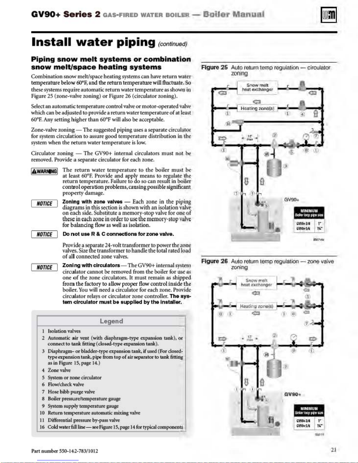
GV90+
Series
2
oAs·FIRED
WATER
BOILER
-
BaUer
Manu
al
Install
Pipi
ng
snow
snow
Combination snow mdr/space hearing sysrems can have
temp
these systems
Figu
Select
which
60'F.
Zone-valve
fo
system
Circulato r zoning - The GV90+ internal circulators must
r
emoved.
melt/space
erature
re
25
(zone-\tal
an
automatic
can
bt
Any
S<tt
zoning-The
r sysrtm circulati
when the
Pro\ride
NOTICE
NO
TICE
water
melt
bel
ow
60'F,
~u.lre
ad
ing higher than 60'F
The retu
ar Jeasr
r
control operation
property damage.
Zoning
d
on each
these
for balancing
Do
automaric rerum water temperature as shown
ve
tempera[U~
justed tO pr
on
r
~turn
:a
St-parate
WF.
erur.n
ttmptrarurt. Fail
with
iagrams
side
in
each zone
not
use
systems
he
and
the
7.0ning) or Fi
O\'ide
suggest~
to
assure
good
water temperature is low.
circulator for
r-n
warer
Provide
problem
zone valves -
in this
section is
.
Substitu
in order
flow
R & C connections for
piping
or
combination
ati
ng
systems
return temperarure w
gu
re
26
(circuJaror
control
\'ll]vt
or motor-optTattd
a rerum water
will
also
pip
temptrat
ttmptrarure
and
urt
te a memory·stop val
as
well
as isolation.
rtmptraturt
be
acceptable.
ing
u.ses
ure
each
zone.
ro
apply
means
to do
so
s,
caus
ing
Each zone in the piping
shown wi
to
use
the
a separate circuhnol'
distr
the boiler must
can r
possible signifi
th
memory-~top
zone
(cootinu
rttu
ill
flu
7.0ning).
ibution in
to
regu
esu
an
iso
ve
vatve.
ctuat
of
lt
lation
for
edJ
rn
wafer:
e.
val
at
least
nllt
late the
in
boiltt
cant
valve
O'De
vah-e
So
in
~
l.hf
be-
bt
of
Figure
26
Aulo r
zoning
<::1
-1
•!
)ltC":i
r::::>
;;-
s
e\Um
temp regulation- circu lator
---
··==
Hcn
tingzono<&
C3
..
......r.
~
·1
I
•t-
--1
:
~
......
6
J)
"'
~
r
(j
..
£l
-·
--
:
~
<::3
_A
~·
·
~
·
~
=''1
fl
\\I
Pro
vjde a
separate
valves. Size
of
all
NO
TICE
I Isolation
2 AutomatK
3 Diaph
4
5 System or
6 Flow/check valve
7 Hose bibb
8 Boiler pressure/temperature
9 System suppty temperature
10 Retu
II
16 ColdwatertiJlline-
Zonl
circuJator cannot
one
from the
bo
iler.
circuJator rdays
tern circulator
vah>es
connect
type expansion tank, pipe &om top
as
Zo
Differential pressure by-pass
to
ragm-or
in
Figure
nevalve
rn
temperat
tone
p-urge ,.aJ
the transformer to
connected zone val
ng wtth elre!Jators- The
of
the
z.one
fa
ctory to allow
You
will
air
vent (with diaphragm-type expansion tan
tank fitting (
bladde
r.t
1
5,page 14.
circulator
,-e
ure a
ut
we
24~\·ol
t
transformer
han
ves.
be
removed
circulators.
n
eed
a circulator for
or ci
rcu
I'MIIt
bt
from
It
must remain
proper
lator
7.0
supplkld
Legend
dosed-type
ype expansion
)
omatic mixing valve
Figure I
gau~
gau~
vah-e
S,
page
expansion tank),
tank,.
of
air
separat
14 for typical
to
power
the
dle the
tota
l rat
ed
GV90+
ne controller. The
the
flow
by
if
internal
boiler
control
each
the
used
(For dosed·
or
to
com
system
fo
r
as shipped
in~d
7.0ne.
Provide
Installer.
k),
tank
fitting
ponents
zone
load
use
e
sy
or
as
the
..
Figure
26
Auto r
e\Um
zoning
S•\owmclt
M&texeM.ngor
F1
"
~
t
r::::>
",
-----
·f
C3
Haating tonels)
C3
• 1l' ..
·~·
u. Q
''L
temp regulation-
~
; .
.,
~·
OVH•
zono;
C1
((I\
valve
Part num
ber 550-
14-2
-783/10 12
2J
Page 22
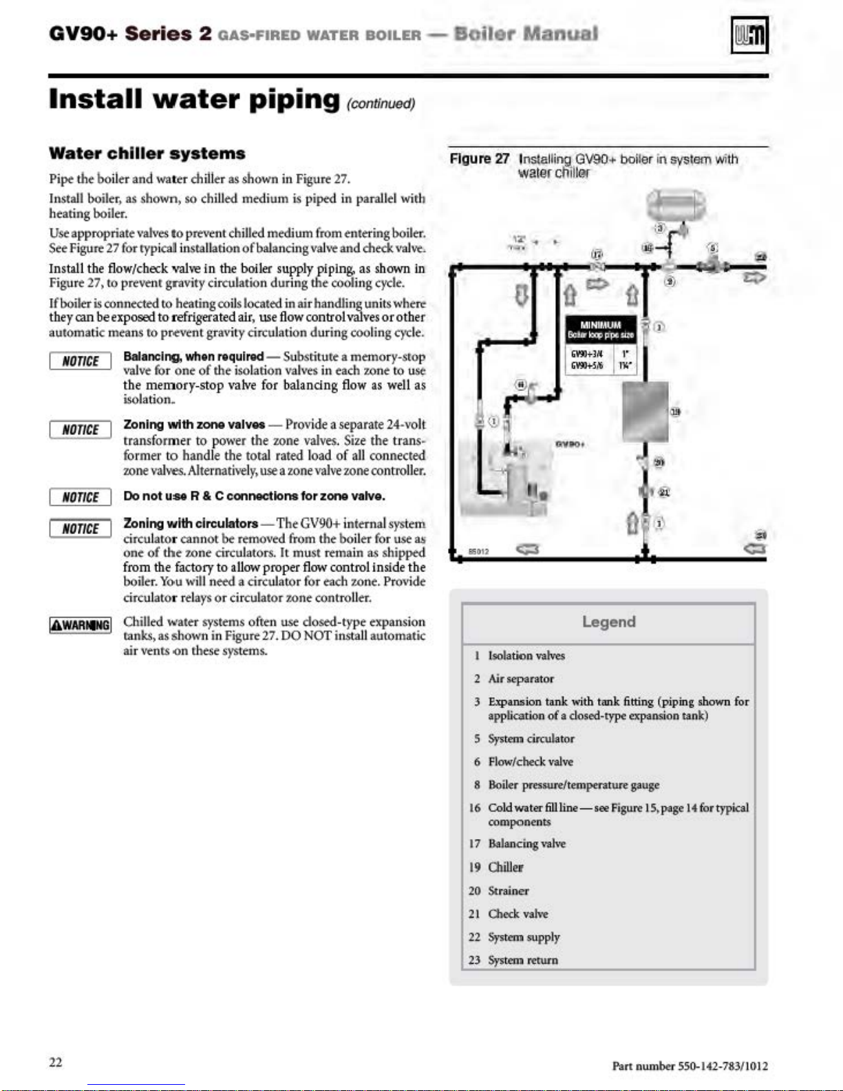
GV90+ Series
2
oAs·FIRED
WATER
BOILER
-
Boiler
ManuaJ
Install
Wat
er chiller
Pi
pe
the boil
Install boiler, as
heating boiler.
Use
appropriate
See
Figur<
Install the
Figure
If boiler
th ey
can
automatic
NOnCE
NOnCE
NOnCE
er and
27 for
flow
27)
to
prevenr gravity circulation duri
is
con
nected
be
exposed
mellllS
Balancing, when
\'lllve for one
the
isolati
Zoning
transformer to
forme.r to handle
zo
Do
water
system s
wa
ter ch
shown>
\•atves
typ
/c.
bec
ne
not
so chilled medium
to
prto\'f
ical i
nstallAtion
.k
''31
to
heating coiJ
to
refrigerated
ro
pr.e\re
memory-stop
on.
wtth
vahoes.
u:se
piping
ill
er
as
shown in Figure 2?.
nt chilled
'" in
the
nt gra\rity
111qulrad
of
the isolation
zone valves -
power
the
Alte.rnati,-eJy,
R & C eonnecUons
medium
of
balanci
boiler
supply
s located in air handling uni
air
,
use
flo
circulati
- Subsriture a memor
valves
\'alve
for balandng flow as
Provide
the
zone
total rated l
use a zone
rco
nun
is
piped in
ng vah"
ng
the cooling
w c-Ontrol
on during cooling
from
entering boil
and
piping,
in
each
parall
check
as
shown in
cycle.
\..Uve.s
1.0
ts
or other
ne
a separate 24-volt
valves.
Size
the
oad
of a
ll
connected
valve
zone
ron troller.
for
zone vatve.
uedJ
el
with
er.
vruvt>
where
cycle.
y-sro
p
to
us
~
well
as
trans
~
Figure 27 Installing
water
clii
'7
~
.
0
•
Q
~
GV90+
ll~K
boiler
@
e::>
il
in
syslam
~
~
rJj
(!)
with
4ij
Q
NOTICE
Zoning with circulators- The
circulator cannot
one
of
the
from
the facto
boiler.
Yo-u
circulator relays or circulator zone controller.
Chilled water
as s
ts
how
()n rh
ranks,
air ven
be
removed from the boil
z.one
circul
atorS. It
ry
to
allow
will
need a circuJator for each
systems
n in
ese
ofren use dosed-type expansion
Figure
systems.
proper
27.
00
GV90+
must
flow
NOT
internal
rtma
in as shipped
control
z.o
insta
er for use as
ll
system
inside
ne.
PrO\ride
automatic
the
asou
Legend
Lsolatlon
2 Air separat
3
E.xp&Mion
application of a closed-type expansion tank)
5
System
6
Fl
8
Boi
16 Coldwater
components
17 Balancing val
19 OliU
20
Strainer
21 Oleck
22
System
23
System
vatves
or
tank with tank fitting (piping shown for
circulator
owlcbe
ck
valve
ler pressureltemperat
6Uline- see Figure 15,page 14 f
\>e
er
valve
supply
return
we
gauge
or
typ
ical
22
Pan num
ber
550-142-783/10
12
Page 23
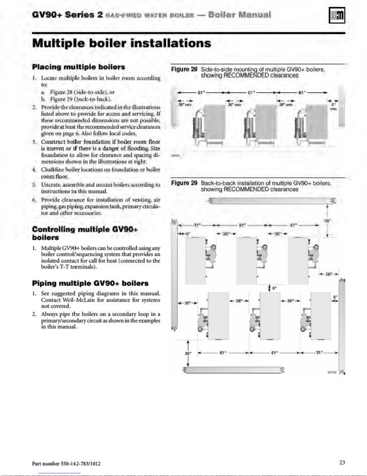
GV90+
Series
2
fl4!i"f'Ot£u WA711'1
••~•1-ER
-
Boiler
Manua
l
Multiple
Placing
L
Loco
multiple
te mu
ltiple
boiler
bulit'n
to:
a.
Fig:u,rc.-28
b.
ngi!Tt
2.
Pnwidt
li.sttd
ab<>vt:
thdt
-r~mmuded
(
.)J'Ov
ide ut l
_givm
on
3.
Construct
ls
un
even
fOundatiOn
mem.lons
4. Cbatklioe boiJ
:r
oom
flo
$. Uoo'a(e, i!il:c:mbleand
instrucfior
6.
Pi'O\>
idc tll."aiance
piping,
r('r'
and
(s\1.1.:-rb-side
29
(baok-t<rbock).
the
de:arancd
to
pn>vid.~
t9St
th~
rt<:O
vase:
..s
.
A.I.Mf
boiler foundation
or
if
there ls a danger of
tO
allow
dlown
in
ft
IOCiltl
oc.
t.s
in
dlil
m11.uuat
fot
gas
pipi
ng_.
~pansion
(tt.hC:r
ac~rits.
the
installations
bolters
in
baiid
iOom accur
j,
or
indicated io
furaccw-
dim~siuo
rnt
nt'lt
fbllow
for clearance and
iUUStnJboo.~
l'm.~
on
mount
in.n:allat:ie)
the-Ul
~trations
tu.H
l
se-rvicing.
s
an:-
nOt
de-d
~ct
cl
local
oodrt.
if
bo
iler
room floor
flooding.
$pacif)g
Ol tight
f:Pu
udatiuu (lT boil
bOilers n«""rding
n or
YC'.rt~og
tank, primary
d.iug
If
:po~ihle,
e-a:rances.
S
ize
di-
.
eT
Ill
,
,
ait
drcul>l
-
Figure
--
Figure
28 Side-to-side
sh
owing
FifGOMME:NOED
w
------
29 Back·l
sh
owing
<>bad<
RECOMMENDED
mounti
~
61
" _
inslallalion
ol multiple GV90+ boilers.
clearanc
___,
___ ••·
es
--
•
o1
muniple GV90+ baii
clearances
O<s
f
)6
,
'
Controlling
multiple GV90
bolters
I. Multiple GV90+ boi
boiler contr
iso
lated con
bo
iler's T-T
Piping
I.
Set'
Contacr
not
cov~red.
2.
Always
primary/secondary circuit
in
this
oVseque
tact
termi
multllple
suggested
Weii-
pipe
tbe
manuaL
for ca
pipi
Mclain for
+
ler>
01
n
be
con
~rolled
ncing
syst~m
tha
t provides
ll
fo
r hear (connected
nal
s).
GV90+
ng diagr
boilers on a secondary
as
bolters
ams
in
this
assistance for systems
shown in the
us
ing any
to
the
manual.
loop
in a
txamp
an
les
1
...
J
~
!
'
-~··_..
_
__
.,.
--
•
-
u·-
I
~
--
" '
--
-:n
••
·
--
Part num
ber 550-
1+2-783/1012
23
Page 24
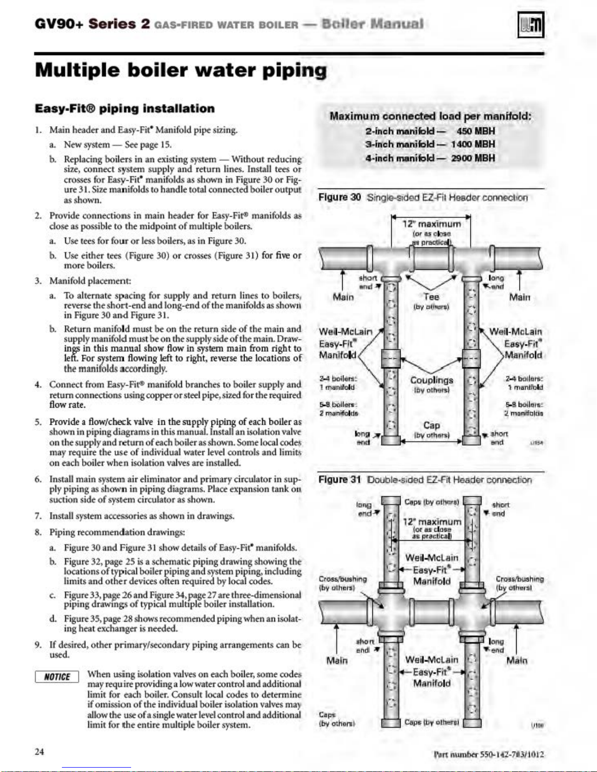
GV90+
Series
2
oAs·FIRED
WATER
BOILER-
BaiiM ManuaJ
Multiple
Easy-Fit® plpl
1.
Main heade r
a.
New
syst<m -See
b. Replacing boil
u,
con
si
crosses
ure
nect
for
31. Siu
boiler
ng
and
E.asy-Fit•
ers
sysrem s
Easy
-Fit• manifolds
manifol
Installati
Man
ifold pi
page I 5.
in an existi
upp
ly
ds
to
handle
water
on
pt
siting.
ng
system -
and return
as
shown in Figure 30 or
toral
Witho
lines. Install
conn
ecre<L boil
piping
ur reducing
er
as shown.
2. Provide connecti
dose as possible to the mi
a. Use
b. U
t~
se
either tees (Figure 30) or crosses (Figure 31) f
for fo
ons
in main header for Easy-Fir'
dpoint
of multi
ur or
less boil
ers>
as
in
ple boilers.
Figure
30.
man
or
more boilers.
3.
Manifo
ld pla«ment
a.
To alterna
rt•terk
in
Fig
b. Return manifold must be on the rrturn si
supp
inS'
left
the
4. Connect
return connections
fl
ow rate
5.
Provide
s
hown
on r.he suppl)• and
may
r~uire
on each boiler when isolarton vah·
6. t
nsra
ll
ply piping as shown in pipi
sucrion si
7.
t
nsra
ll
system
8. Pipi
ng
a. Figure
b. Figure
locations
limits and
c.
Figure
piping dr
d. Figure 3S,page
ing heat exchanger
te s
pacing
the
sho
u
~ 30 an.d
ly mani
fold
in
this manual show flow
. For
sys
tem flowi
manifol
from
ds auo
Easy-Fi
for s
rt-
end
and
Fig
u
~ 31.
must be on
ng
rdingl
r»
manifold
using
copper
upp
ly
long-end
rhe
supply side
left to
righ
y.
branches
or
stet-!
and return
of
the
lines to boil
manifo
de
of
the main and
lds
as showt\
of r.he main. Draw-
in
system main from right to
t,
re't-erse
pipe,si
the locatio
to
boiler supply and
ud for
the
.
a O
ow/c
.berk v
alve
in piping diagr
r-eturn
the
use
in the supply piping of
ams
in thi.s
manual.lnstalf an isolation
of
each
boil
of
indi
vidual water level
es
er
as shown. Some local
art
installed.
eac
h boiler
controls and limits
main sysrem air eliminator and primary circulator in sup-
ng
diagrams. Place expanston tank Otl
de
of
syst.em circulator as shown.
acctSSOries
reoommendation drawin
30
and Figure 31 show details
32.
page
of
typical
or.her
33.
pa$e
awmgs
25
is a schema
boile
devices
26
and
of typ
28
shows
i.s
as
shown in drawin
gs.
gs:
of
Easy
-Fit• mani
tic
r pipi
piping drawi
ng
and
system
ng show
piping. including
often required by local codes.
Figure
34.
~e
27
art
r.h~-dimensionai
ical multiple boiler insraUarion.
recommended piping when
needed.
an
9. If desired, other primary/secondary piping arrangements
used.
When
NO
nCE
using isolation
may
requ-i~
pro vidi
limir for each
if omission
al
low
of the individual boiler isolation
the
we
of
limir for the entire multiple boiler
ng
boile
r. Consulr
a s
ingle water
\'ll]ves
on
a low
water conrrol
each boil
loca
level
J codes
conrrol
system.
er.
some codtS
and
add
ro
determine
valves
and
add
tees
or
Fig
ourput
ifolds
a!l
fi
't'e or
ers,
ns
of
required
as
val~
codt$"
folds.
ing r.h
iso
lat-
can
bt
iti
onal
ma)
iti
onal
Maximu.m connl!cted load
-
Figure
We
ll~
Easy-Fir"
Munllold
2..4 boll6tr.:
1
a,~anlt
5oo
8. boll
2 manifol.ds
Figure 31 IJou
t-
Cross./Dushfn
{by
olh~:~
Molh
Cap
-.
(by
ot
2·inoh
-3-
manifold-
inch manifold- 1400
4-inoh manifold- 2900
30
Single-eided
cU.ln
old
err.
I
r.l
Of'IQ
ond
g
...
~
)
..
.,
1.•
bte-s
ided EZ.fit
C.p,. (b_V athcr,f)
,-
~·
12-maxlmum
•.:
Wel
Weii-Mcl.ain
hertl
EZ~it
iot aa close
as
tac:IJta
i..Mclain
Easy
-Fit'
Manifold
Easy-Fit'
Manifold
pl!r
4SO
MBH
MBH
MBH
Head
er connection
.,
'·
1-toade<
,-(
,.
'
·"
ll
~
man®ld!
Maht
We
ii·Mclaln
Easy-Fit•
M
an~ol
~
8
bolle•s:
:tmon "rfolds
CQnnection
·.short
..
.00
l
o119
-.
ef'ld
Ma
in
d
24
l-\ln num
btr
SSG-14'1
-7llll101
'2
Page 25
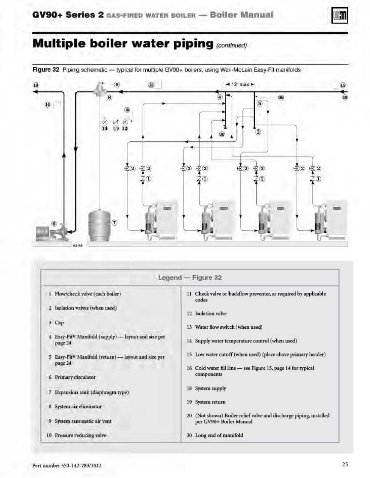
GV90+
Series
2
us-Fu
ltD
WA
tla 110
11.1!11
-
Boiler
Manu
al
Multiple
Figure
32 Piping schematic - typiClli f
boiler
...
.. (8'
1
·
~
VI
~
@@
®
~-
®
.....
water
or mufti pte GV90+ boilers, using We;I·
@ I
i>l.l
I
:>;
@
'
~
piping
...;(2)
>.
CD
t
-
~
~~
_L,
I
--
l;t =
\
..,
~J
J
---~
,_.
I I
(2)
)
j
--
(c()
nlinuedJ
@
@
=
Mcla
r-
I
>.
® >
'
-
in
Eas.)'
.f'
il man
ifolds
..
@)
(
3)
@
(!'
@
j
®'f®
;
'
=
~
~~
__,~-
I
r
..,.~
4
1_
,_
__)[
@
-=
Flow
/che
~
Gop
• e'"' FFi"'
p
age-
2'!1
~
Ea")'
•Fi"'
page-24
7 l!xpandoo
8
S}'J
tcml
air
JO
Pres:ru~
Legend-
ck~
~du.::in
(each
bailer
~
MntUiald
MluUfold
tank
elimi.o
----------------~------------------------~
(MJp
ply)-~J<>utaad
(,.IUlO)- by(>utaad
(dl
aphrogm
acor
g vaJ
typr)
~
sit•
I"'
ol>•per
Figure
II
Check
codes
12 Isolation
13 Watertlowswi.tch("·henused)
14
Supply water temperarure control (when used)
low
IS
16 Co
components
18 System supp
19 System return
20 (Not shown) Boiler relief
per GV90+
30
Long
32
valve
or
rbacJdlow
vaJ,-e
wa
.ter cutoff (when used) (place above primary header)
ld
water
6U
tine-
ty
Boi~
end
of
manifold
see
Manual
prevent
Figure I
valve
a:.
as required by applicable
S,
page
and
discharge
14
for
typical
piping. installed
Pan-number
ss
o..-•14:2:-783
/ lO
ll
25
Page 26
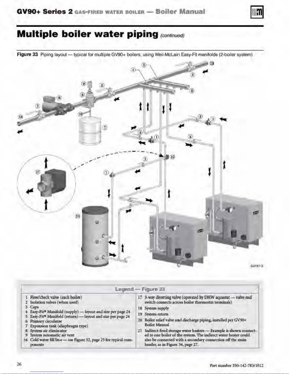
GV90+
Series
2
OAs-f'IR£D
WATER
BOILER-
Boiler
Manual
Multiple
Figure
33
Pipi
ng
.
__...--
t
--......_.
(
..
boiler
layOOI
- Iypical tor multiple GV90+
water
~
-·j:
-:J
.....-·
....
..
,
-"
\
!
I
~
·
v
_ ..
"""·
~
(!)
piping
bQ
ilers, using Well-Mc
~
{
-··-··-"
•
---
11;
~
(continuooJ
lain
~
(j)
..
l
@
Easy-fit
........ ®
manijold<!
(2·boiler
t
system)
t
I Flow/
2 lliolation
3
4
5
6
7
8
9
t6 Cold
dlock
c..,.
E.uy"Fi'*
t;asy-Fi~
Primary
P~sion
Sy$tt.m
Systqm
pont:ots
valves
M>n
M-anifo1d
drculator
air
cf
automatic airvtml
water
va
lw
(I!Jllh
(""
••
.
ili>ld (supply)
(return) -
tank
(.diaphragm type)
bn
in atnr
611
Uo.e-see
21
boill!f
)
US<!d
)
-18)1JU
la}'"'
F!igur~
"32.
u
t~d-siu
Ut
and $iu
p;:~ge-
per P•8" 11
percp3ge
25
(or q'pkal
Legend-
2
~
cnm--
rigure'J3
~~~~~~~~----~~1
17 3-
WII)'diwrtiogvai••
$Witch cooneus
I
~
S)'Stem
supply
19 Syuem return
.20
Boiler
rc(~fva
BQi.Jer
Manual
"'21
lndired -Gua storage water
td
fO
ane
bOi
a.
~
ler
neq('d
io
Figure.J4
aJso ~ c;q,o
beader,
f
op"'""'
.acmM boiler
l
v·e
a~d~:arge:
Q(
tht~tm'4
~
th
thermo.stat wmi:Qals)
heaters-
Tbt
a
gecond.ary'copnc«ion off
ptgtt 27.
1
bjl
ptplo
OHW
"'fWISiat-valwend
g,
i~11t
aU¢
pq
~xa.mple-
indi~Ut
is
~"'llter
G\!'9()f
shown oonnect-
beater
coulj:)
the
ma1n
P.ut number
55()..142-783110
11
Page 27
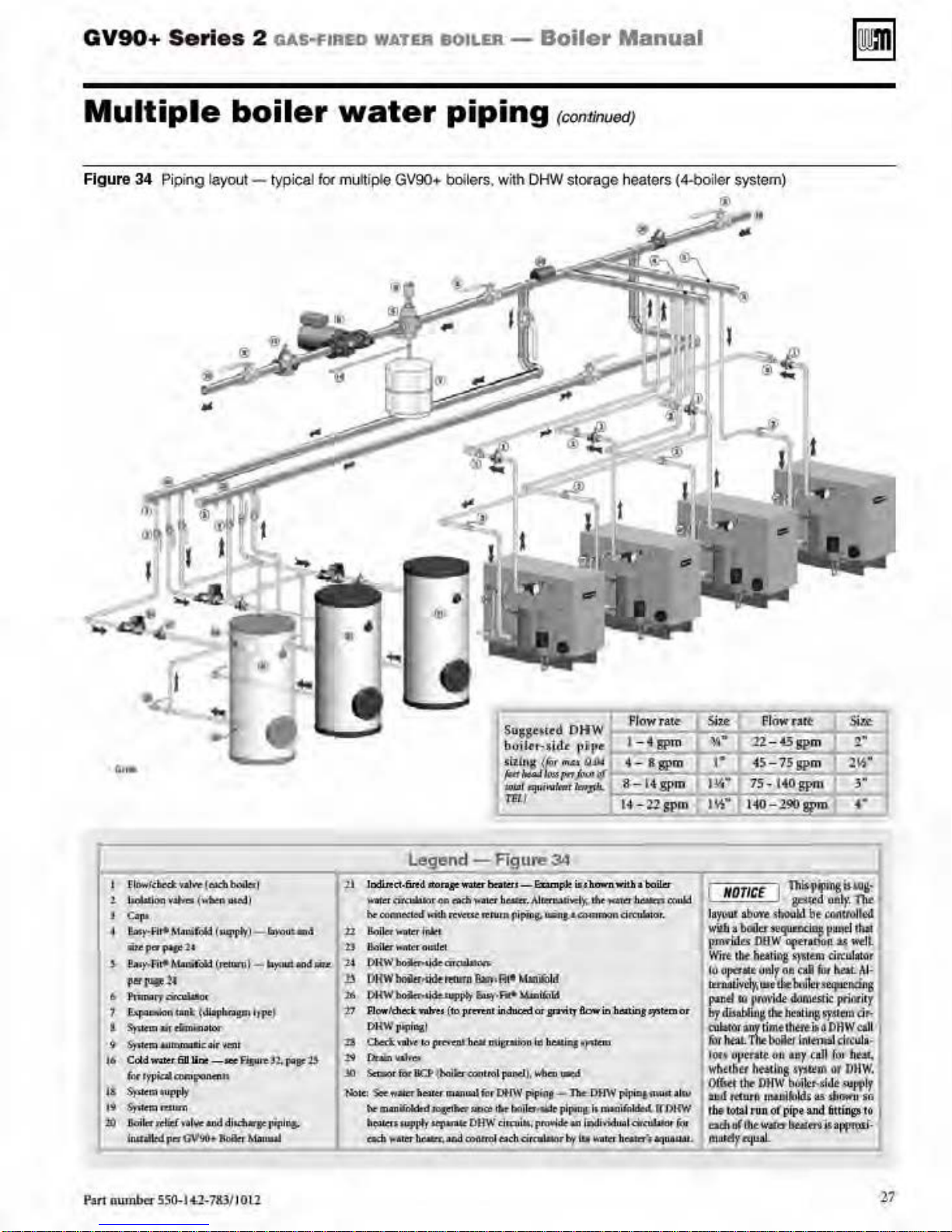
GV90+
Series
2 GAS•FIIIED
WATER
BOILER-
Boiler
Manual
Multiple
Figure
34 Piping
layout- typical for muniple GV90•
,,,
~·~··
I
'
~~
...
•
.e
~·
boiler
I
water
piping
!;>oilers
.
w~h
DHW storage heaters
(continued)
(4-l:;>oile
r system)
..
..
Jilnw
ft:
h«t-nlve.(ed
!
.boiMlocl
,.._
.
"""
•
l!tofy-,(:1,-M;n
llit.e~pace
~
1!.-yrF.tt
M•llifold
,.,
..,.u
.
&
'"""'
"'~
'I
£:(poao~l
otHant
1
!li)1
~m
til
riA'niaaiOr
9
s;
11cm_.,,unm:aai
J,a Cold
wuer-
·6D
fqr
fYJ*al
qv:npc
U:
S):ucom
...
1'.,.
jj
S,l
lll!
l"! IUIJRl
1JJ
Jkriler
rdid; 1o'
Jnsul
kd
re"
GY'oo-t
Pan
number
.ss
a-•e-783/ 1012
bqilerf
('<
~lMtd
i'*
(
rtq~pt,.
1
~
{retatnl-
(
Jiarhtayn
r
~lr ~~
Ji~:~~~
-RIL"
uwn
n
Afw
and
dldl.
JlolerMlntul
)
)
'-'
lilyoute.J
.._)CIIIi
lind
!Jpe)
Fqjure
'J.
-paF
,e
Jilti
n&o
•~
"U
27
Page 28
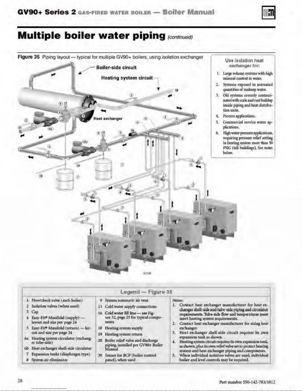
GV90+
Series
2 OAS>f'IAED
WATER
BOtLER -
Boiler
ManuaJ
Multiple
Figure
36
Piping
layOUI
boiler
- typical f
~
,..
~
·-
...
water
or multiple GV90+ boil8fS, using isolaliQn excl1anger
Boiler-side
Heating
piping
circuit
system
circuit l
t
(contlnuedJ
u
l·
. -
f.
·~
--'
""=·'
...
..
.m
@ "'..:._
!)
U
ttl
aolation
~t
excm.nver tor.
I. la
rgt-
voluiUL'
.sy'Atm.t
wltb
m.ln
utl
tootua
t
ill
w~r
.
1.
Syitem.s
a-posed ta umuat
quantities
J.
Old
llllled
imidt
ti
...
rro~appticat
5.
Commu
p
6.
Kl_gbwar.erp~USU
"'qu
ill
PSIG
bclow
ol
-systtrns
with
ale
piping
on
oniu.
cial
lhtit~OS
.
lr-ing prtssure
b~
Ji.ng
sym.m
(!aU
hWldUlg!.)
.
maknl
p
watt:r~
s:tn•n lr
oontamt-
and
rust buildup
and
htat
disrrilo-.
i
ons.
strvia
W3ltr
rtaJ191.ications
rdief
setting
~
t
ba.n
.
&.
bigb
td
a
~
50
ooltS
1
Flow/che&vaM (ea
l WlbJfua \•aJvet (
j C.p
<
E•
lf·Fil•
byo
.3
F.ls:y
ow
6a
Headn:g
tf'
lib Htat tKba
1
~""""
A
S)'"lltetn.alr
Manifol
ul
and il,U
~
Rt-
M:an
ana
~7..!
~
tu~liidt
)
nseuhen4_.1&-
ranb (
dimlnuor
wh,en
fM:r
tfol
l
:!ft'
'Pap!-
dn:u
Ch boOtt}
w~
)
d (supplf
~
ili>phl'Ogm
pagt-l.t
llmiru)
1.4
Jat
or
)-
(t'ldbt
clrculunr
..
-lat·
•g~
rypt)
~~·
9 SfSttfW
I
~
Co
ld
I(; Cold
woe
""""
13
f(brlnj')'"""'
19
HearinJ'ys.ltm r
20
f5oik:r'
l~lp
"""""'
~
$ensor for
paa
Legend -
1hHOrn:l tf.:
wa.te:r
W3.t.E'r
32,
p.-
rdief
lng,
fnallllltd
BCP
d),
when UIC!
~
I
I
Figur&
air ftiU
~ppfy
catlnt~.."'lto
6Ji
line-see
25
(or
"PPir
eru
Y'lllve
ptt
{OOl~tt
d
Fttt'
rypi~l
cu
m
;md tllsdtiu¥t
G¥901
conuol
l
\1
mpo
Bofler
-
36
NO~
I. Coftll
2.
3.
4. liealirl
5.,
tr
htt1 ttcllangu fllll.nuf
~-.<ideao.Snol><
nqu.i.mnents
ft'Wf
Can.r.ac1
e:uhwga.
Kn.a
dp.aruion
a\~n.
•15tem
~
boiler and
~
Thb~Udt
ht:tt
fng
~
~n
ht:a1excban!Jff
ex.:hangH>
S'f'
and
iudh'\dll21 il00itla
-
shell~$id
ttn~
liS
tan diodu'eqllin!tl
plus
ii's
a-
beat
cscb:ang«
J,eyd
con
,sid<ari~"6
fl
ow
ttqtilmnenu..
manl1f
e.
UIOW!'I.
wn
relief
vaM
r!iping
11
'i
nok
may:
atutrer
and
t~cw
circuit
illi
ATCt
lll
\'e\
M rtqu
own
fot
and <i<i
tempuatll!'W
m
ror
ild113 heat
~ulm
~p
anlli
co
111\ll~
and
comi'Oft¢nll..
A('
I!
mt!tl,
indiv:fduitl
Jr«l
ha
t
f'X
·
DIIIIII'
mus
t
lu:
own
(ln
tmt.
J~eatins
28
P.art
nu
ulb«-
55()..
t
~2-7it.ll
101!
Page 29
GV90+
Series
2 OAS·FIRED WATER BOILER -
Boiler
Manual
Venting
GV90+
suD!llled
lllll<in
d•acrtbedln
Every
00
appliance.
Inspect finished
thoroughly
dl
an
pro:vided
applicable
Fai
lure ro provide a
•ten
ptr$0nal in
If
NOTICE
tibe
cov-.ertd
can
in
staJiation>
assistance. Other configurations
be
available.
Where vent piping
en
mhNt•d
l inch
on
unbeated space.
Installations
r
equirementS
Fuel Gas
instaJiationsorCSA 8149.1 orB
for Canadian insta llations.
Use on
marual
tings.
If
used, • matonry
ONLY
vent
piping musr be instaJied
in dlis manual and
sealed. The chimney
only for
appliance or
to
the
straight.
an
d air pi
wi
th
cbimmey
ac~
teriiOr
The chim
m~r
alt)f
Fa
ll.u
personal injur
proper
&
air
bollero
with
olr ualng piping ond methode
bolter
NOT
com
carouldon end
thts m1oo11.
nwtt
common ve
to
ply wirh t
and with aU requirements
must
have
ven
ensu
-
bo
vented ond
tts own
nt
wi
th
any
t and
aJr
re aU
art
he instruct
general
piping
airtight
<Odes.
prope-rl)•-instaJJtd
t and air system
jury or
will
death.
cau..st
vent/air piping confignratlons
in
the
nor
bt
GV90+
app
lied for a particular
contact
boiler manual
Weii-Md.ain
lo
routed through
spac•> appt)• minimum
of
the
roil-faoed
length
Code,
fiberglass
of
the vent pipe
must compl
and
y wi
with the National
ANSI Z223.1 for
insulation
th
ly the materials listed in this
for
ven
t and
aJr
pipe
and
See
bo
and
Figure 40.
uood
air
pipet
page
chlmn•y
eo o PIPE
- The vent
aU
joints must be
33.
CHASE
and
as
instructed
musr be used
GV90+ boil
fireplace
chimney.
with
ping
ers.
NO
OTHER
can be connected
The chimney must be
no
offsets. and the
materials
must
comp
this instruction manual. The
must
be
fitted
with a sealed
optning..
of
be
ro
verify
rt
to comply could r
ry
through
the chim
in
ney
can be inspected.
ney
(and liner. if installed)
sptcted
ar
leasr once annu-
condition.
y.
death or substantia]
damage.
which
esu
lt
the in-
in
Yenll·
v•nt.
other
ions
of
seve-
re
for
may
in
the
locaJ
U.S.
149.2
fit
-
can
lor
a
ir
venr
ly
severe
When
common
The QVSIO+
applanc•.
the
boiler
may
vent. because the venr may
ANSI Z21.13.
rt:maining
removing a boller
bo
\"/hen an existing boiler
GV90+ boil
requires
cause a probl
is
on
the old common
vent
Its
system
..
r
cannot
er CANNOT
own
vent
em
for the appliances that rtmain on the old common
intended to
from
be
co...._
is
use
the existing common vent. The
and air piping,
be
roo
large.
check
for proper operati
vent
systm'l
an
..-ted
replaced with a
as
specified
The
following test. requi
.
existing
with..,.,
GV90+
in
this manual. This
on
of
the appliances
GV90+
Vent system verification
Ar
the time
followed
system
to
the
i
ngs
Existing
of
with
placed
removal
each
in
operati
of
appliance remaining connected tO the common \'tnting
<>n. whil
common vtnting sysrem
in the common
vent
·.-~nting
test
an
exis
ting boiler> the foll
e the o
rhe:r app
are not
in
system.
procedure
owing steps sha
liances
remaini
operation. Stal
any
ng
connected
unused
(The following is intended to test whether the spplisnces
remaining
sstlsfsctorlly.)
I.
Visually inspect the '\'tnting
and determine there is no bl
other detkiendes wbic.b could cause
2.
Te
windows
remaining conntcted
other
nor
fans,
ate at maximum
fireplace
3.
Place
structions.
4.
Te
burner
a
5.
Aft~r
to
~return
other gas-burning applian
Any
improper operati
so the installation con
- latesr edition. Correcr by redetermi
installations must
on
sn
existing vent system
st
·.-
~nt
syst~m-
and
Insofar as is practical. close aU building
all
doo
rs between the
to
spaces
of the buil
connected
such
as
r
ang~
to
dampers.
in operation
Adjust
st for
spillag~
operation.
cigarette,
cigar,
it has b«-n determined rhat
the common venting
doors,
ned
usi
ng
the appropri
comply with
ding. Tum on cloth
tbe common venting
hoods and bathroom exhausts, so th
sp.eed.
d:le
appliance
thermostat
at
draft
Use
the
or pipe.
windows.
on
of
f'o.rms
will
operate
sysrem for proper size and hori7.ontal pitch
ockage
or
restriction,
an
unsafe condition.
leakage, cor
rosion
doorS
spac~
in whi
ch the appliances
the common
Do not operate a summer exhaust
so
hood
rel
flame
system
exhaust
ce
to
common \'fnti
with the
·.-
~nting
sysrem
ar~
l
ocated
es dryers
system.
and
Tum
any
on
appliance
any
ey
will
fan
being inspected.
appliance w
ief
opening
of a matc.b
each
appliance remainingconntcted
F<>Uow
the l
ighting
ill
operate continuously.
aft~r
5 minutes
or
candle, or smoke from
properly \'fnts when tested as o
fans
.lireplacedampecs, and
their
Natio
pre't'iOUS
nal
ng
system
Fuel Gas
conditions
sho
uJd
Code,
of
be
corrected
ANSI
use.
sizing to approach the minimum size as
ate tabl
es
in Part 11
6149.1
or 8149.2 Installation
of
that
code
Code
. Canadian
exhaust
. Close
of
utJi
Z223.1
ot.,..
boiler.
red
b) •
ll
be
open
or
and
and
oper-
in-
main
ned
any
.
-
Part
number
550-14-2-783/10
12
29
Page 30
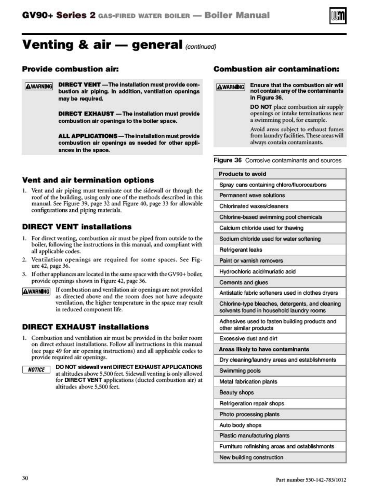
GV90+
Series
2
oAs·FIRED
WATER
BOILER
-
Boiler
Manual
Venting
Provide
IA
WARMIMG
combustion
DIRECT
I
butdon
may
&
VENT
olr piping.
be
required.
air-
air:
- Tho lnotallotlon
DIRECT EXHAUST - The lnttlllotlon
combuatlon
ALL
APPLICAnON
combuatlon
lnc
M
Vent
1.
DIRECT
1.
2.
3.
and
air
v~nt
and
air pipi
r
oof
of
rhe buil
manual
configurations
ding.
See
Figure 39. page 32
and
VENT Installations
For
direct
venting.
bo
iler, following
a
ll
applicable codes.
Ventilation
u
~ 42.
page
If other appliances art located in r.he same
pr
O\ride
openings
the instructions
open
36.
If
combustio
as
direct~d
ventilation> the higher
in
reduced
air
openings
1lr
openlngt
In
th•
apace.
termination
ng
mu.sr
t~nninare
usi
ng onl)• one
piping material
combusti
ings are required for some spaces. See Fig-
shown
on
in Figure 42, page 36.
n and vtnrilatio n
above
and
component
general
mull
provide com-
In
oddhlon, vendlotlon openlngo
mutt
to the
boller
spac•.
S- Tho lnlllllodon
as
nCMidcld
options
our
the
sidewall
of
r.he
mer.hods
and
Figure 40. page 33 for allowable
s.
air
must
be
piped f'rom ou
in this
manua
space
with
air
open
the room
temperature in
li
fe.
does not
mUll
for
other
or
r.hrough
describfii in
tside
l.
and
compliant
the
GV%+ boiler,
ings are not provided
have
the
space may result
rconunuedJ
provide
provide
lppll-
the
r.h
is
ro
the
with
adequate
Combustion
Figure
36
Corrosive contaminants and sources
Producto
Spray
Permanent wave solutions
Chlorinated
Chlorine-based
Calcium cllloride used
Sodium chloride
Refrigerant leal<s
Paint or vamlsh removers
Hydrochloric acid/muriatic
Cemerlts and glues
Antistatic
Chlorine-type bleaches, detergents, and cleaning
solvents
to ovoid
cans containing chl
fabr
loood
air
contamination:
Ent...-e
not
lnRgure36
DO
Optn
a
Avoid areas
(rom laundry facilities. These
always contain conram i
waxes/cteaoo<s
thM
th•
contain
combutdon
any
of
the
.
NOT place
ings or inrake
swimming
swimming
used tor water softening
ic soft
ene<S
In
household laund<y rooms
combustion
term
pool>
for
subjtct
for
ro
oroA
iuorocarbo
pool chemicals
thawing
acid
used In clothes dryers
contaminants
inations
examp
exhaust
nants.
air
air supply
le.
artas
ns
wtll
near
fumes
w
ill
DIRECT
1.
Combustion
on dir
(S«- page 49 for a
pr
NOnCE
EXHAUST Installations
and
ect
O\ride
exhaust
r~uir
td
DO
NOT
at
alritud~s
fo
r DIRECT
alti
tudes
w nrll.arion
insra
ir
ope-ning i
air openi
sidewall v
abo\rt
above
llari
ons. Follow
ngs.
5>500
VENT
5>500
air
nstructions)
ent
applications (
must
DIRECT
feeL
feet
be prO\'ided
all
Sidewa
30
in
the
boiler
inst
ructions
and aU
EXHAUST
JJ
venting is only allowed
ducted
in
this
applicable
APPUCAnONS
combustion
room
manua
codes
air) at
ro
Adhesives
other
Exoossive dust and dirt
l
Areu
Dry
Swimming
Metal fabrication plants
Beau
Refrlgeratloo
Photo
Auto body shops
Plastic maoolacllJrlng plants
Fumiture
New
used
to
fasten bulldlng products and
simflar products
likely
to
hove
contamlnontt
dea:I\Jngllaundry areas and establshments
pools
ty
shops
repair shops
processing plants
I'Qf
inishing areas
bu
ilding construction
P-an
and
establishments
number
550-142
-783/1012
Page 31

GV90+ Series
2
fiA!i-fUt£u
W
Ar
Ill
lltliL£R
- B
oiler
Manua
l
Venting
Ma
nifolded
opti
on
for DIREC T VENT
multip
I. Multiple-
IAWMitNGI
Air mani
le bolter Installations
GV90+
busliuo
-a
b.
c. Prttvid"
d..
e.
3it
manifold.
Tht rumbosliffo
.!i~twall
,.,,
&c
C<.ltnb
.a.nd
Provide. tJ'rirumu.rn
(O.
2,000 Bb.lh
(fcumb~t
~ts
h
(
and
sld"
btlow
in~d
mi
gNdi!/'.'.11U\~
t tuu
Vtot tt::.ttidio
tD
prc>lcll~
ll.'i<J~
ned
ON
NOT
vent pipes must
rnlnated
tbi.l
c6mpU:ndll
co1nply
injury, death or substanti
damage.
fold sizing
& ai
comb
of
fOrminilnU
air dud$.
nimum
tow
nl
.
LY
air
use
llllWUAL
ust
boiler~o
ait
l
th~
rtlt
vonla
tho
building
dtarnnc-c.
li
ne
a$
&tr
n) Of 1 square
boll<r
o.it
d.u.r:npt"r
QJkrutiun
piping""'
combined
Individually
Flue go.lcakliS<
damage
co
uld
res
r-
ion
111
Wit' a cuunnun com-
~
mwt
must
Ianni
).
tn'-t:
r
W:i~
ro
.shown
lllb_
in
lnp
uc
is
W.ed,
dc'tfl
be
vent
be
routed and ter.
general
air
be locatt.d
nolo
ctiOna
adjacto.L
in
l!lguu
d
uct
(adju!.
Inch
Wi
tT
t after
romblntd.
piping.
.., dt"SCrib<d
•M
cau
OCc\if;
ffillk('_
ult in .st\·
erce
al
proper
pc-r.souaJ
in
a
on
lht
l
are;t
()f
*aU
~7.
ttd
par
fb
bo
O-
damper
DO
All
in
bo
il•t
Il
l
ty
(con
Figure 'D
v
•
I
Figure
38
Th
is
sy!T1
to
repres~mt
unU8dJ
Combustion
lndlvidualvenls)
---.
-------4------"t-
Maintain
ma
()
bol is
al vent options
clearanc.,.and
nffold i
nle
.
u~cd
tJoelow
air manilold oplion (combined air inlet,
- rrusl
comp
-,.·-
ly with Figu
.....
H
re 4
1,
page 35
= =
placement between the air
l and
any
app
lia
nw
~
.....
vnnl
falt~
vent as
1'
5ild
db
,..
WE!I
ow
shown
below
'}
Sld~dl
"'
uol!ng
but
I.
See Figure 110, page 104 for minimum cross
tional
area
of
2.
CALCULATE
combined air
requi
red
OR
ducrs.
cross
S«t
ion (for ar
square inches):
a.
MIN.
AREA •
BY2
3. Example:
a. A muhi p
boilers has a toml input
(500,000
b. The required ducr cross sectio
c.
MIN.
AREA •
TOTAL
l.e boil
MBH
er system
of
Sruh).
560
DIVIDED
•
280
sq.lnchu
The
aJr
manlfold inlet of
with
regard
to
spacing
mlnatlons and
aJr
restrictions shown
(NOT
VERTICAL
VENTS M
UST
BETERMt
INPUT
with
4 x
140
nal area
BY
from adjacent boiler
inlets with
in
Figure
) shown
t:a
DIVIDED
( 4)
GV90+5
= 560
MBH
is:
2
GV90+
NATED
boilers
the
clearances
41,
page
in
this manual for d
sec
-
in
is
pac
speolJUld
35.
The
THROUGH
{e
}
OK
~~r.r7777~
t
of
dlteot vent
venta.
To
avpid
In
Flgu" 38.
ve.nt
tennlnatfon
ir
m.. \ttnt urdlr.:ct
THE SAME
DO
1101f
PLACE
- D
c<>
nne.
ollo
r«f
rcuiEition,
~·•s•
c&
nfigurtttfon
t-xhaust
SIDE
W'ALL
VI!
NT
~
SMCE8&0W
~rr777777~~n
ns.
It
rs
nrit d.a.ssilitd
how~Vt1'.
Jl.
The
sid~wa
AS'
THE AIR
l'tltt
can b
H
ttnninalif.>n
you
must
e.
MANFQ.D
a.D)'
mu\t ius
of
as
b<
l
p<;~.<<l
tbe-sldewa.JI
..
Ttll!
a forceiial!
rallt.he
l
(all'owl
itLiitttllatimt$
INLIOT
Intake
\'tnt tcr
ug
methods
.
THE
.
~~·
.-
I he
Part
number
550-1+2-783/1012
Jl
Page 32

GV90+
Ser
ies
2
o111riutna
wA.TUt
UtliL&tl
-
Beller
Manual
Venting
Figure
39 QV90
.
NOnCE
1
Vtn~
S«the-d«
Well-M
venUairap Separate
&
air-
+ venl1119
J
eog:
Lh
alf'tt.U
.. ~ values-
CLain 3"
general
•
nd
air pipi119-0PTIOIIIS
boil~
input
-
tht
gi\'t'n in Fjgu
(AI
(cof'>l>usdoo a.lr piped
PVC
pipes
f!!. 109,
Malll
(Mini
mum length for
opplrcoiioru includeo/lowonce frJrtf>e lermlnoiion frtffng!)
DIRICTYEHT
3"PVC
Concentric
!Not• IJ
(CDnL)
and
boiJa
nutomati
pagt-
103.
T'ht
mum vent
~
boiler frorl\
PIPING LIMI
l."ally
dtrilJe$
longt"t'
and arr
••
- l
outs
ide)
TS
tb
rump01Sa~
th(!'
~n(,
ltllt
mure.
pipe le
ngt
lcnfonalsl,...,
3'
PVC
Conao
ntHc
(Note
11
tor preilll.l"t
tht
input is
hs
(CI>O>
DI
RECT
buS\!Oh
loss-
tluoug
reduec:d.
EXHAU
at•
b L
fr0l11
inside)
3"PVC
Coupliflg
he
ST
vm
L
Nom
-3
-5
1:
Seepage
i
OO
i
OO
1
00
i
OO
Equiva'-nt
• 7 feet per
. 16
feet
Use
only
PVC
IPEX
3• P\oe
5636
compliance
kl~
use
only
Contac
tWe-11-Mcl..aln
37
fHt
fo
conc
Seepage39
i
OO
iOO
iOO
iOO
for
.,bows-
for
each
r •ach 3·inch short-radius•lbow
pipe
DO
NOT use
entriC
vent kits
Is
required
IPEX
product c
for ordering
ded
uct
3-ln
ch W long4radlu
CPVC
can
.
~or
ULC
od
e 1
96006
lnfoiTllafl
or
be
5636
used
Seepage
from
ASS
for 3-wnnng.
4 i
Max.
Length
(fee<)
i
OO
iOO
i
OO
iOO
maldmum
sor 45° elbow
with c
oncentric
with
standard P\oe
compliance. all
on
and
availability
·
~
-
]
~~
See page
equiValent
pipe,
43
Max.
Leng
1h
(feet)
00
1
1
00
1
00
1
00
length
of
termination
pipe, fittings
fittings and cell"'ent must
ofWeiJ.M
kitS
clalnv
I•
..
-
~
~
See
poge
Ml!IX.
Leng
lh
·(feet)
1
00
1
00
1
00
1
00
pipi
ng {does not apply to termination fittings}
.
and
cell"'ent (ANSI
enfl
ng
kits.
.:]
(1-
·
45
Seepo
/AS
TM
be
IPEX
System 636. When
ge5
Max
.
Length
(feel)
100
100
100
100
01785
.
1
) except
--
Seepo
Max
Lenglh
(fee
100
100
100
100
whei'Q
uSing
'
ge53
.
l)
UL
C
IPEX
32
Pan
nu
mber 55
0-142-783/10 12
Page 33

GV90+ Series
2
OAS·FIRED
WATER BOILER -
Boiler
Manual
Venting
Figure
I
Vent
or air
fitting&
PVC &
cement
40 Ven
l
ocal codes
tom
pipe
a.
ASS
p
iptl
&.
pftner
t •
&
nd
air
•lr
p
ipi
ng
I'VC
I'VC·OWV
CP\IC
SChed
ABS1JWV
CI'VC
ABS
-
general
,.
temolo - Use
Matortol
SChed
....
40
(-1)
....
40
(Note
Sdledule
40
(Note
I'VC
(HOle
1)
(Nole
t)
(cont.J
on
ly the materials list
Unhod
Plastic piping materials
AHSVASTI.I
AHSVASTI.I
I)
1)
AL29-4C
piping
AHSVASTI.I
AHSVASTI.I
AHSVASTI.I
AHSVASTI.I
AHSVASTI.I
materials
ed
below,
SUndordo
St.IM
0
1785
026115
F441
02681
025114 & F656
F493
022:35
ensuring thai all materia
for
lnaboii.Uona In:
Clnodo
Plast
ic
vent
pi
pe
ULC $636
Ai
r pi
pe
tett
if
acce(ltable
must
when required.
can
be
aiY)'
for
of
k)cal 00de1.
ls
be
certified
(Nott
those
meet
2)
li
sted
to
at
Yen<
pipe
AL294C
·-I
--
Weii-Mcl.ain
bird
e<:nMr\8
Note
1: DO NOT
Note2
:
I
AWARMIMG
IA
WAIIMING
IA
WAIINING
Heat
fab.
I
nc.
-
SaJ·T.Yenl"
Z·Fiot
I
nc.
- Z·
Venl
ll
Dur
a·Vent-fasNSeal""
-
Fa
b, I
nc.
-
CORRIGUAIIO
W..ii-McLain bird ocreen
3"
ve
nt
screen:
W·M part number
use
DWV,
IPE:X
PVC concentric terminati
only
IP
EX
System 636
AL29-4C
I
and.
pipe manufacturers unless using apters specifically designed for the
Plastic piping-
I
DO
I
ve
nt
use
piping
cellular
at the termination
NOT
IA
383
-500-1
05
CPVC or
- Install a
Do
not attempt to connect differe
WAI!MIMG
ABS
pipe
, fittings
(when
U.<li'J
core pipe.
I
ALL
when usi
ons
ut:il.iu PVC pipe/fittings certified to
and
PVC·to-stainl
Weii-Mda
ve
nt
ng
concentric
cement.
ess
in plate
and air pipes require a
Certified
appfiance
o (purchase
\'Wt
adapter supplied
or
concentric
nt
rypes
of plastic pipi:og together.
include the bird screens. Purchase bird
supplier if nor included. (
Note-
for
category
vtnting
sepa~ately
terminatio
n.
un.c
by
the:
PVC termination
pwpos
BIRD
SCREEN
SO'tt-n
bird screening
IV
and direct V9nt
Use
ON
56'36. Where ULCS636 compliance
vent pipe man
e by the manufacturer.
Ill
s separ
i.s
in
-
)
LY
PVC
schedule 40.
ufa
cturer
).
00
NOh lermln.Uon.
areJy
regnal
at
NOT
mix piping from differe
f'rom Wtii·Mcla
ro
the WeiJ
the
boiler vent
-Mclain
is
MoSt
in or vent
sidewall
required. use
connection
nt
vent
kirs
do
not
kit
vent
•
Part
num
ber 550-1
4-2
-783/1012
cap, supplied
standard with aU
GV90+
b.:.ilers.
No
add
iti
onal screening is required.)
33
Page 34

GV90+
Series
2
oAs·FIRED
WATER
BOILER
-
Boiler
Manual
Commonwealth
Commonwe.tth
the boiler must
(a) For
all
installed in
whole
owned
side wall
above finlshed grade
nor limi
sha
ll
be satisfi
I.
INSTALLATION
TORS.
tal
or gas finer
monoxide
is insta
to be installed. ln addirion, the insraUing plu
fitt
carbon monoxi
each
tu
equipment
owner
sionals for the installation
detectors
a. In
b. In theevenL that the requirt:mentsofthissubdivision
2.
APP
ca
the above provisions shall comply wi
ANS!/UL 2034 listed
3.
SIGNAGE. A metal
be permanent!)• mounted ro the
in
directly
horizo
equipment. The sign sha
one-half (1/2) inch in size,
LOW.
be
sidewa
eve
or in part fQr residential purpoStS, including r.hose
or
ope-
exhaust vent termination
ted
rodtcksand porches, the foll
ed:
Ar
the
venred
ll
ed
er shall
additional!.,;~
re served by the si
to secure the serv
the evtnl thar the si
fueled equipment
atric. the hard wired carbon monoxide detector wi
aJa
rm and baue:ry back-up
nex
t adjacent floo
ca
n nor be met at the time
the
tion,
to comply with the abo\rt requirt:ments; provided.
howeve
battery operated carbon monoxi
aJa
rm shall
ROVED CARB
rbon monoxide dertctor as
g at a minimum height
in line with the exhaust
ntally vented gas fueled hearing
KEEP
of
MasNM:husetts
··n
stalled
by a li
censed
ll horizontally-vent«! gas-fuel«! equipment
ry dwel
rated
gas
det~cto
li
ng) buil
by
the
Common
in
th
e area of the venting, i
OF CARB
time
of
installation
fueled equipmtn
sha
ll
obser
ve
r
with an
ON
that a hard wired carbon
aJa
on the floor level whe
observe that a batt
de
derector
of
de
It
shall
be
ery
wirh
th
e
dwelling, building or struc-
wall horizontal vented gas fueled
the responsib
ice
s of qu
of
hard wir
de waJJ hori
is
instaJJed
r level
owne
r sha
JJ
ha\rt a peri
r, that during said rhirty
be
insraUed.
ON
MONOXIDE DETECTORS.
rtquirN.
and
lAS cert
or
plasti
of
ll
read. in print Si
"GAS
CLEAR
OF
ALL OBSTRUCTI
of
Massachusetts
- When the
plumber or
ding or structure used in
wealth
is less
than se\·
oo.v
ing requirements
MON
OXIDE DET
of
rht
side
r,
the installing plumber
rm and battery back-up
re
the gas equipment
operated
an
aJarm
il
ity
alified
ed
carbon monoxide
zontally
in a crawl space or
may
bt
of
compiMi
od
of
(30}
de
detector with
in accordance with
th
NFPA
lfieci
c ident
lfu:a
~t~rior
eight (8)
feet
•tent
terminal
VENT DIRECTLY
gas
fitter. R
and where
ncl
the
tn
(7) feet
uding but
EC-
wall horizon-
mbtror
or hard w
i.s
insra Ued on
of
<he
licen
sed
prop<rty
pro
•tented
gas
ire
fes-
gas
an
th
installed on the
on
of
installa-
thirty (30) days
day ptri
od. a
an
Each
720
and
be
tion plate shall
of
the b
uil
d-
above grade
for the
applian
7.t
no
less than
ce
or
BE-
ONS.•
OO
iler is
ead
and comply w
4. INSPEC
··nstalled w·nhin
the Common
·rth
the instructions below.
nON.
The state or locaJ
side waJJ horizon
no
t approve the installation unless. upon inspection.
th
is
d
e inspec
signag~
248
(b)
EX
EMPTIONS: The
248
CMR
I. T
he equipme
Not
of
NFPA
2.
Product
equipment installed in a room orstructureseparare from
the dwepa
rt for residential purposes.
(c)
MANUFACTURER REQUIREMENTSVE
NnNG
tor
observes carbon monoxide detectors and
installed in
CMR
5.08(2)(a) I
5.08(2)(a) I through 4:
nt listed in Chapter I Oentided
Required
To
54
as
adopted by the
Approv<d
lli
ng. buiJ
SYSTEM PRCNIDED. When the manufacturer
Product Approved side wall hori
ment provi
de
s a venting system design or venting system
components with the equipment,
th
e manufacturer for installation
b)•
rhe
•tenti
ng system shaU i
I. Detailed instructions for the instaUation
syst~m
design or the \'fnting sysrtm components; and
2.
A complete parts list for
v~nting
(d) MANUFACTURER REQUIREMEN
VE
NnNG
tu~r
fue
led equipment does nor provide the parts for
fl
uegase
ing requirements
I. T
bt
i
2.
T
by
d u
t) A copy
(
side
wal
system.
SYSTEM NOT PROVIDED. When the manu
of
a Produ
he
referenced
induded
nstruetior~s;
he 1'special
rhe
de
of all
l hori7.0ntall)
~
b
ut
ldentifie
Bo~u
rd.
a parts l
installation i
ct
Approved side waJI hori7.0nta11y
sh
all
..
special \rtnting system " instrucrions s
with the appliance or equipment installation
and
\'fntin
and
i.sr
and detailed installation instructions.
• vented
instructions. all parts lists
\rtnting design instructions s
or
equipment
:ar
the completion
installations
wea
lth of
Massa
chu
setts
,
gas
inspector
taJ
iy
•tented
gas
fueled equipment sha
acco
rdance wi
<hrougb
followi
ng equipment is exempt from
Be
Vented
" in rhe most current
side wall
horizontally vent«!
4.
Boa
th
the provisions
rd; and
ding or structure-used in whole or in
GA
S EQUIPM E
7.0
ntaUy vented
the instructions provided
of
the equipme
ncl
ude-:
of
the-
v~nting
TS-
s"s
pecial
venting
be
satisfied
gsyst~ms
by
.. shall
the instructions for that
sysrem
GA
S EQUIPM E
sy
stem
the manufacturer:
be
Product Approved
sys
n.strucrtons for all Producr
gas
fueled
equi
pment. all
for ve
nring instructions. and/or a
hall
remain wi
of
the installation.
th
of the
..
Equipment
edition
gas
fuel«!
NT
gas
equip-
nt
and
the venting
design or
NT
fac
•t~nted
gas
\rt
nting the
s~
the follo
hall
tem
sha
U in-
Approved
ven
ting
the appliance
ll
of
of
-
w-
ll
34
Pan
number 55
0-
142-783/10 12
Page 35

GV90+ Series
2
OAS·FIRED
WATER BOILER -
Boiler
Manual
Vent
Figure
~
T
hese
at
GV
termination
41
The vent term
For
Can
,,
ho
sym
VENT
.
bols represent
t
ermina
r-;:::::====;-1
DO
D
requirements
inatio
n mu
st
adia
n in
stallations,
be loca
defer
ted
to
the re(Jli
to
.....,..
...
IC
v~nf/alr
plate
tions
MINIMUM CLEARANCES
-
"'"
meet all
rernents
SldeW~~I
ven
req
uir
emen
of
CSA
~)
;
wi
th
sep~rate
t 6 arr pipe!!
ts
bel
ow
(also
appl
ies
8149.1 or B149.21nstal
~
Sidewdl
direct
exhau
st
DO NOT TERMINATE:
to
vertical vent termin
lat
ion
Code
.
..
Shle~l
conoentrtc
ations).
p
t~
._CHU4CIU
liQUI
.....
NT
DO
~~::;;~;I.
i
If
wrthl n 1 o
i
~bon.
,.;jf~
FORCED
........
flO\ _
'01 -Direct
..
,
AIR
Direct
vrmt-
12•
exhaust-
DO NOT TERMINATE:
48,
METER,
ULII:F
REGULATOR,
YA&Jt&.
etc..
•oo•
-
Sfeetmln
WALL
,
DO
NOT
.......
··""'--
Plillbllc
........
'IUr!T 6 feet mJn.
DIRECT
VENT
SYSTEMS-
Moold
IPI*
"""'
liddlea
~n
reti~IIIOII
~UIO
....
®
Alroldpo
_
...
............
-
....
..
mc••d•to
...
12lnehes
GRADI
Part num
ber
550-14-2-783/1012
or
SNOW
mln,
LINE
00
NOT
lll!mlilllle
**•Window-
co
ebc.
cauK
Ice
fQrmaDorll
DO
nn
tb0111t
a
huund
35
Page 36

Page 37

GV90+
Series
2
oAs·FIRED
WATER
so1un
-
BaUer
Man
ual
DIRECT
Allowable vent/a
length a
NIN
GI
the
not
39,
ven
t/a
termi
subj«r
Use only
listed
adapt
termination such rhar
ng
exce-ed
page 32.
rmination loca tion
ir
cap
nation must
termi
by
foreign
to build
IAWAII
I.
Locate
and vtnr pipi
will
Figure
Determine te
I.
The
Figure ~ page 38.
2.
The
limitations shown in
Locate the
3.
damaged
or
VENT
ir
pip
e materials &
the
vent
in
Figure
40,
ers
if
spec.i.fied
f'rom
the boiler
the
maximum leng
mu.sr
be
comp
Fig
ure
nation
obj«rs,
up
of lea\'fS
so
- Sidewall with
materials
page
the
to
installed
ly with
41>
page 35.
it
is
such assrones or balls,
or sediment.
and
33. Provi
the
not likely to
de
total air piping
termination
th given
as
shown
dea
rances and
kirs
pipe
in
in
bt
Figu
W-M
re
43
INSTALLATION- W·M sidmwall ven
·
<:Oil
-
~
vent/air plate
-
..
<iii)
Va
lr
pla
ta
Multiple vent/a
I.
W
hen
rerminaring
rermin
are
ir
terminations
m ulri
ple
GV90+ boii
each vent/air connection
as
described
in this manuaL
I
AWAIININ
2. Place wall
anct
For
GI
as
shown. in Figure 44 for U.S. installations.
Can
vent pipes
t~rminare
poss.ibility
dea
tll or substantial property damage.
pen~trations
adian
installations. provide clearances re-
and
at
the
of
sever~
to
obra
air inl
same hei
personal
in minimum
ets
ght
All
quir edbyCSA 8149.1 or Bl49.21nstallationCode.
3.
The
air inlet
ven
t connection.
intak~
\'fnts.
4. Combustion
1\>
lded
N
OTICE
o-f a GV9G+ boiler _is parr
It
is
not dassified
with
r
~g.ard
to spacing from adj
a.i
r (NOT \'f
as
shown in Figure
The Weii-M
capo
can
pi
pe
using the manifolded
air opt
cat
ed
ure 41. page
clain
be
used
for multiple boil
ion.
The
following
35
of a dirtct
as
a f
act
nt
pipin
g)
can
~7,
page
~
1.
venr/air terminati on
ro terminate the •tent
er
app
lications
combust
vents
must
the
restricti
and figure 38, page 31.
ons
must
to
a\'O
inju
dea
orced
nr boil
be
man
be loin
Fig-
Ns,
ion
id
ry,
r-
air
er
i-
St
ep 1 lkadand.
proCCKid
page
St
ep
2 Install the
all \'f
Sttp3
Make
follow all fnstruc'tKms
wtth
29
through
b<>iJer in a locati
nt
and
sur~
tile selected sidewall termi
plies with Figu
must also comply wi
St
ep
4 Use only
Provide pipe adaprers where required.
ep
5 Vent piping
St
St
St
St
Step
St
\<a
ep
6 Prep
plates
\'fn
ep 7 The Weii-Md..ain
piping from the boiler
ep
8 Install venr
air termin
roward the boiler at least 1/4 inch per fooL
general guidelines.
9 Ins
\'frtical
ep
10 Install a
the
the •tent materials listed
lues sllown
are
the .sidewall penetrati
as
instructed in th
tla
ir cap
and
atio
tal
l pi
pe
runs.
hanger
pip
ing.
venValr Installation until y
page
35
air piping ro the
r< 41, page
th
Figure 44, page 38.)
and
air piping lengths
in
Figur~
3~.
-"
on
page 38.
air
n plate. Slope hori
is
p
lat~
terminatio n musr
to
pip
ing between
supports every 5
suppo
rt
within 6 inches
fn
.
on
that aJJows pro
se-lect~
35.
(Multiple boiler sid
in
page 32.
ons and
section.
the termination.
1..0nt.al pip
fffi
on both the horizontal and
claili
manual.
ou
hav• r
per routing
sidewall location.
nation
location
Figur~
4
0.
page 33.
must
not
exceed the
secur~
the sidewall
See
''lnsta
JJ
Weii-M
be
installed before
the boiJ
t r and
ing downward
See
pag
of
any upturn in
DO NOT
•ad
com
ewall
plates
cla
the
wntl
~
48 for
of
-
in
Part
number 550-
14-2-783/10
12
37
Page 38

GV90+
Series
2
oAs·FIRED
WATER
BOILER
-
Boiler
Manual
DIRECT
In
sta
ll
Weii·Mclai n vent/air
I
NOTICE
1.
I The i
tify
su
Locare
tennin.ari
a.
Use
the
b.
Locate
the template
penetration
c.
Makt
sure ther.t w
proper plactmen t
d.
Use
the template
bole
s,
flue
leve
l.
For the Wtii-McLa
ensure
in Figu
peMnal injury,
e.
Cut hol
marks made with the tmlplate. For besr resul
es
VENT
ns
ide and outsi
the exhaust (vent) and
re to
orient
on
opening and
template
supplied with the term ination kit.
is
co
be
of
to
pipe
and air
t
he
flue
re
45. Fail
in
the
wall
dlameter ,longdrill bit to drill
air pipe openin.gs
inside and outs;ide.
f.
The
cut<l
holes
2.
Dri
ll
holes for the screws or plastic anchors
plate. lnsta
pl
ate
(temporarily).
a.
CUt
the \-t
b. Cut the air pi
air pipe agains
c.
Temporarily
Slide the inside wall
on
the inside
flue
pipe
ul
(as
if desired.
Jl
the
the
flue
nt
pipe t:o fully exttnd into rhe termination socket.
. Then drill the large openings from both r.he
and air
marked
outs
ide plate and
pipe
so
pe
so
r:
the
slide
the
W"a
ll.
d. Position the inside
downward s
e.
Mark r.he four (4) mounring hol
f.
Remo
and mounr the inside plate.
3.
Test fit
butts againsr the i
4. Apply silicon
and
ensure a tight seal around the \-t
5.
S&u
scr~s
the
vent pipe fully pen
slide onro venr pipe. Rotate slightly
~
the
and lock washers
ii
gMy
ve the \-tnt and air pi
't-ent/air
terminat
termination on
trrates r.he termination socket and r.he air pi
nte
rior stops.
RTV
se:alanr
ion
- Sidewall with
cap
de
cover
pl
ates
are
stamp«!
in
rakt (air} openings. Makt.
tht
plates co rrttd
a..,.oid
on
the outsi
made.
ill
be
no
obstructions rhar might prevent
the term ination.
mark the locations for the four mounting
pipe.
Level
in
plart,tht
and air pipe
ure to comply could result in severt.
death or substantial property damage.
as
shown
in Figu
cen
pipe
may
on
th
e
templ
the
extension
the
exrension through the wall wiJI
stops inside the termi nation.
flue
and air
plateO\'fr the two pipes and into position
plate
so
the
towa
rd
the boiler ( t/4" per foot).
pe>
to
the interior
nt
in
pl
ace
using
(s~
Figure 46).
y.
obstructions:
de
building surface whtTt the
th e template
template must
will
be
side-to-side, as
re 46, using the location
tering
boles
be
run through a
ate)
in lieu
of
to
secure
mount
the
tenninarion on r.he
through
pipes
flue
es
for the plate.
drill
the
pipe.
the
the
thr
ough
pipe
and air
the
four mounting holes,
vent pipe.
of
the
to spread r.he silicon
fo
ur
#10
vent termination
x
to iden-
with
a spirit
be
l
evel
shown
t:s,
use
a small-
for
the
flue
and
rec
tan
gular
two
ll!parat<
the
outside
wall
will
cause
buu r.he
tbeopening(s).
pipe
slope
Make
sure
'11"
sheer
met
tu
the
pe
to
Ill
W-M
Figure
Figure
Figure
vent/air plate
44 Multiple
air
aif
45 Hoi
vent/air p
46 Tenninalion assembly- Well-Mclain
Vfi'lt/~r
leml
pla
le
- c
in
take o
tO
preparatioo
lat<'!
pl~e
inations- Wail-
looranoo from
lth
e next
'"wall
(use template provid.ed)
rconunuad)
Mcla
vMr
- Weli
·Mclain
in vooV
of
one
10
.......
38
P3n
num
ber
550..1<42-7831101"2
Page 39

GV90+
Series
2 OAS•FIRED WATER
BOIUll
-
BaUer
Manua
l
DIRECT
VENT
- Sidewall with separate pip
Allowable vent/air pipe materials &
length a
I
AWARNINGI Use
I. Locate rhe term ination such that the
piping and vent piping
terminati
length giwn in Figure 39, page 32.
Determine termination location
I.
The
air
stalled
Figure 49,
2.
The
renni nations must comply with d ear
and limitation.s shown in Figure 4 t. page 35.
3. Locate the terminations
ro
be
damaged
srones or
or
sedi
I
AWARNING
Multiple vent/air terminations
I. ·
whe
n rermin.aring
renninate
scribed
lA
WARNlNG
2. Place wall penetr
clearances
U.S. installations.
providedea
81
49.21nstallar
3. T
he
air inler
direct
ven
forced
adjact-nr boil
4.
Combust
manifolded
only
the
\'t
nt
mattTials and kits
listed in Figure 40, page 33. Provide
pipe
adap
ters
if
spedfu!d.
tot:aJ
f'rom
the boiler ro the
on
w
ill
n
or
exceed the maximum
and
\'t
nt terminations must be in-
as
show
n in Figure 47, page
page
40.
so
th
ey
are not likely
by
forei
gn objects,
baJis
..
or subject
ment
.
Do
oot
ex~
I
of
~f
0\&tJid¢
rhe
V¢0'
Figu:re 47, page 39.
exposed ro the outside
fr~zing
pi
shurdown. In
mares,
arou
la
chas~
the ve
be
each
in this manual
All 'lent pipes
!
te
avoid possibility
in
damage.
shown
of
condensate in the vent
pe
:. res
ulting in
extremely cold eli-
insrall an insulated chase
nd
rhe
vent
rly when usin
musr aJiow
nt
protected f'rom water.
vent/a
rm inate
jucy.dear.h
r
a.ncesr~uir
glo
pipe,
and
multip
ir
and
at
rhe
ors
ations
to
in Figu
For
Canadian installations,
edbyCSA
to
buildup
maximwn
piping shown in
Excess
potentia
piping, particu-
ngerlen
for i
insulari
le GV90+ boilers,
connecrion
same
of
St\·
ubsrantial properry
obtain
re 4
such
of leaves
ive length
co
uld cause
l boiler
gr.hs. The
nspttrion
on
air inlets
height
ere
personal
minimum
8,
page
Bl4
ion Code.
of
a
GV9()+
t connectio
air inrake with regard
ell'
vents.
ion air
as
shown
(NOT
bo
iler
i.s
part
n.
It
is not c.lass
\'ent
in Figure 37, page 3
ified
to
spacing from
pip
ing)
39
anct'S
lengths
as
40
9.1
can
air
and
as
of
must
de
must
ro
for
or
of
as a
be
1.
-
a
Figure
47
INSTALLAllON SEQUENCE -
,..,.. lin
Sttp 1 Read
Sttp
2 Install the boil
Sttp
3 Make sure the selecced sidewall terminati
Sttp
4
St
tp
S Prepare the sidewall penetrations and
Sttp
6 The air piping m
Sttp
7 Install \'eat
Sttp
8 Install pipe supports
Sttp 9 Att
Sttp
10
Sttp
11
and
(cHJow
vonVIIir inalallatlon
piping to
ure
41, page 35. (Muhiple boil
Figure 48, page 40.)
Use
only
ers where required.
values shown in
in
this section. See •prepare wall peneuation
The
ven
1rom
Siope horizon
foot. See page 48 for general
Install a hanser support within 6 inches
ach the
shown above, as needed to ensu
The vent and air pipes may run
\'C!O
C and air
must be nwuntained. Space braces no furth
External \'tilti
the
\'tnt
the mdo:sute as shown in the illustration
cl
earances.
er
the selected sidewall location.
the
veru materials Listed in Figure
Fig.ure
t piping must terminate
the
air
Jnlet as shown above. See illustration above.
and
ai:
tal
wmt
tmnination exterior
pipes
ng
and air pipes. The
--
all
inscructiom; in t
until
in
a 'oat bon that allows proper routing of all \l!
Ve
nt piping and
39,
u.<;t:
termi:nate
r piping between the boiler
piping downward coward the boiler at
e'l'e:f'Y
must
be
greater than 4 feet requires
es
Separa
te
pipes
s ioowall
.....
MS:
manual. DO NOT
you
have
read-
on
'ocation compli
er
sidewall places must
40.
air
page
32.
secure
in
a down-tumcld elbow
in
an
guideli:nes
5
feec on both the horizon cal and vertical runs.
piping
re clearance
up
secured
as
with braces, and all dearan
ven
t a
nd
page 33. Provide pipe adapt-
piping lengths
the sidewall plates
s•
on
tlbow
pointed
and the
.
of
any upturn
: Use either
abo\>e
high
as
4 feet with no en
er
ttum
an
air cenninations
insulated enclosu
above,
mainc
proceed
29
U.Ough
es
also
comply with
must
not exceed
page 40.
grade or snow
24
as
as
shown above.
outward
sidewall openin
least
114
in
the piping.
of
thec.onfigunttions
clos
ces
inches aparc.
must
exlc through
ai:ning
all
-·
nc
with
instructed
or
Lin
and
re
required
with
35.
and
air
Fig
the
INlay
&$-
inch per
e:.
ure.
The
lengths
around
-
Part
number 55
0-
1+2
-783/10 12
39
Page 40

GV90+
Series
2
oAs·FIRED
WATER
BOILER
-
Boiler
ManuaJ
DIRECT
NOnCE
Fo
combusti
an
sidewall
foll
F
VENT
r multip
on air
elbow as
re:rm
owin
g the restrictions
igu
r~
3*, page 31.
le boil
er applications using the manifolded
option, the \·
in
Figure 4
ination pl
Prepare wall penetrations
1.
Air pipe
a.
2. Vent
a.
b. Inserr a galvani
3.
Use
of hole centers. Sidewa
Wtii-Mc
4. Foi!
through
5. Seal exteri
pen~rari<>n:
Cut a ho
desired to the
pipe
Cut a ho
le for the air
air
pi
penetrat ion:
le for
the •.-
pipe. Si.ze
pt
outs
mt
pipe. For eith
combustible ronstrucrton,
la
rger than
• 4•
shown
a sidewall
Qw
all
the vent
h<>lef<>r
in
Figu
tenninarion
lai
n sidewall vent/air pl
1~1
floors
or
or
ope
pipe diamete
3• PVC
ud
mrtal thimble
re
49.
JI
t~mi
«14~1
fQ
walls.
nings th
plate
r iw latiQn
oro
ughly with exteri
- Sidewall with separate pipes (co
tnt
can
7>
page
39,
.are.
The vtnrs must
in
Figure 41, page 35 and
the
a
ir
ide diamettT.
er
bt terminated
or in a coupling or
be
pipe hole
combustible or no
located
as
dose
in
as
n-
siu the vent pipe hole ar least 0.4»
r:
in
the \'fnr pipe hole as
as a remplart
narton
plates are included with the
att
kit
of
. shi
pped
v~nt
for corr
with
pip¢
or
cau
«r
each
wh~
n
Jk.
location
boiler
paning
Figure
~
1
2'"
minimum b<t
aru
hl!jaeen
mta
ll
braces
man
24
48
Mtllip
t
~~e
no
inches
l
esepara~
wetn
edge ot
ot
pipe-
more
---
apart
pi
pes
air lntal<t
Vf/11
-..
nvnuedJ
si~alterminalions
pipe~·
""'
, ... t
Termination and
1. Prepare the
by inserti
mus
manuaJ for parr
2.
When
atlea.st
above
3. You can
ward o r
Figurt 47. page 39.
ng
t
be
purchased
completed>
12 inch
grade or sno·w li
ori
90
fittings
vtnt
term
ination elbow
bird
~n.s.
numb
the
es
~low
ent
the
degrees away from
(See Figure 47. page 39.) Bird
St-pararely. See
ers.
air
termination
rhe vent
nt
as
shown in Figure 47.
vent re:rmin
terminatio n
arion
tht
4. Maintain the required dimensions
pi
ping
as
shown
in
Figure 47. page 39.
For mu
5.
6.
Do not
shown
pipe.
NOnC
ltiple boil
exte
in
E
er terminat
nd
txpOStd vtnr
this
document Cond
If
txrtnd.ing
inm
ll •
eoupling
the coupling
ions,
s~
pipe
ensate could fr
the
vt-
nr
and
on
eaeh pip!'.
flush with the outer
and
tht
air termination elbow
tht
parts li.sr
coup
elbow either dir« dy
air
inltt
of
the
Figure
outs
ide
air pipes
ar the
ling mu.sr
and
at
pagt
t lbow
finished termination
48>
pagt
of building
ttte
and
out
from
Mounr
plate
the
.
screen$
end
of
this
be
ori
ented
least 12 inches
39.
our-
as
shown
40.
more
block vent
pipi
th1111
the waJI
ng
wirh
in
Figure
4g
S.Ciewa
separate pipes
,
j
1hnl
pp;~
l MrPfiaJ '
3
~
l~crniOO~na
~1nW¥-wsllllrf
f
.t
Qalo>~llUmlllir.r
,
ll ter
rri
nationassembly - usi
5
plifh:r
~
latit
lJrr.w.lkl
1
irJrin
~
, I
1'
®
'!!t~
.
filnl
.tmoQ!.IJ)I
inodalb
Aiiilild
....
tll>mJ
~p~
n,.(ftlll~
ng
-
. •
5
)
40
l\lrt
number
55(1-142-783/101'2
Page 41

GV90+
Series
2
oAs·FIRED
WATER
so1un
-
BaUer
Man
ual
DIRECT
Allowable vent/a
VENT
ir
pip
e materials &
- Sidewall with 3" concentric
length a
I.
The
3" concentric ttrminarion kit must
chased separatel
IAWARHI
2.
3. This termin
NGI Useonl)'the
locate
the
and vent
tion w
iJJ
not
supplied
r this el
nor exceed
Figure 39, page 32,
is
maximum vtn.tlair pipe lengths include aJJowance
fo
Determine te
I.
The
con
ct-nrrk
as
shown in Figure 50, page 41.
2.
The
terminatio n must comp ly with
limitations show n in Figure 41, page 35.
3. Locate the
by
aged
subj<!<t
for~ign
to
y.
ven
t materials and kits listed
in
Figure
40,
page
33.
Provide pipe adapt-
ers
if
specified.
termination such rhar the total air piping
pip
ing from the boiler ro the term
the
maximum length
ation
~quir
es
bow.
with
a 45-degree
the te
rmi
e-lbow
nat
ion kiL The
rmination loca tion
termi
nation
kir
must
be insraUed
deara
termination
build
ob
jects, such
up
of l
so
i
ris
eaves
or
not
like
ly tO
as
ston
es
!Miment
or
be pur-
ina-
gi\re
n in
that
nces and
be
dam
balls,
or
Figure. 60 INST
-
·-·
ALLAT
ION SEQUENCE -
c::_NT
To boi
ler
Concenlric
hofizontal
Multiple vent/a
I. ·
when
re:rminating multiple GV90+ boilers. install
each conct:ntric t
manual.
IAWAR
2.
Plac~
clearance as
insta
cl
earances r
Stallation
3.
The
ven
intak~
vents.
All
HIN
GI
min.are
sib
il
su
bstant
wall
penetrations
shown
llations. For Canadian insrallations. pr
equired
Code
air inlet o.f a
t connection.
wirh r
ega
ir
terminations
erminatio
v~n
t
pipes
at the same hei
ity
of
severe
ial property damage.
in Figure 51, page 42 for U.S.
by CSA 8149.1 or 8 149.2 In-
.
GV9G+ boiler is parr
It
is
rd to spacing from adjacent boil
n as described in this
and air
personal in
not dassified
to
ght
obta
inlets
to
jur
in
as
must
avoid pos-
y.
minimum
of a dirtct
a f
death
O\ride
orced
ter-
or
air
e:r
Sttp
1
Read
and
proCCKid
page
St
ep
2 lns
all \-t
ep
3 Make
St
plies with
terminati
St
ep
4 Use onl)• the
PrO\'ide
ep
5 Vent piping
St
\<a
lues shown
St
ep 6 The
befor~
St
ep
7 Prepare the sidewa ll penetration
terminati
th
is
terminati
pipes" on page 42.
St
ep
8 lns
concentric
downward t-oward
pag~
S!tp
9 Ins
\rtrtical runs.
St
ep
10 lns
the
fo:llow all instructions in this manual. DO
wtth
ven
29!hrough
taJ
I the
b<>iler in a location that aJJows proper routing
nt
and
sur~
tile selected sidewall
Mgu~
ons
pipe adapre:rs where required.
concentric term
piping
on
stctio
n.
on
taJ
I venr
48 for
tal
l pipe supports every 5
taJ
I a hange:r
pip
ing.
Valr
page 35.
air piping ro the selected sidewall location.
41
. page 35.
must
also comp ly with
v~nt
ma
and
air piping
in
Figur~
from the
kir
and
PrO\rid~
assembly.$«" 'Insta
and
air piping between
\~ntlair
g~neral
termination. Slope horirontal piping
the boil
guidelines.
suppo
Instal
lation unti
re:rmination
(Mu
terials listed
l
~ngths
39. page 32.
ination must
boil~r
ro
secur~
the
cove
the s
u..r.ports
er at least 1/4 inch
feet
rt
within 6 inches
hav
• r
NOT
•ad
l y
ou
of
location
lti
pi~
boiler co ncentric
Figur~
St.
in
Figur~
40. page 33.
must
not
exceed the
be
assembled
the
termination.
-assemble
r plates
indicated
ll
t~nnination-
the boil
on both the horizontal and
of
as inst
er
any up
and mou
per
com
page 42.)
and
insraU
th~
conc~ntr
ructed in
nt
concentric
and
the
foot. See
turn
in
-
rh~
td
i
c
Part num
ber 550-
1+2-783/1012
41
Page 42

GV90+
Series
2
oAs·FIRED
WATER
BOILER
-
Boller
ManuaJ
DIRECT
In
stall te
I.
IA
WARMNO
2. Wall penerration:
3.
4.
I
AWAIINING
rmination
Assemb
nat
ions,
le
the ventr
on
I If
pag~
ntct
outer pi
ensu
re
pro_per
in
flue
injury
a. Preferabl
thimble. carefully use
4l4 in
must pr
i
nset
Secure the termination in
outside
Btfo
re
cent
ri
as shown in Figure
y.
use
ches
in
O\'
ide a solid srop for the rain cap ribs, as shown in the
to
Figure
wall
or
outer thimble pl
lxg
inning \"t
c tenninarton. mount and secure rhe concentric terminatton
The vent
I
must not
properly support
venr
pi
injur
y,
VENT
- concentric
ermination
41.
ssa:-ry.
you
can
pes for
a shorter
r.he
pipes
bun corrtcd
ly assemb
gas redrcula
or
diamet
52.
and
ping
death
le the concentric terminati
dearh.
.a
th
imble wi
a hole saw to cut a ho
er
through the
place
nt
and air piping from rhe boiler to the
52.
page
42.
air piping must
rest
its
v.-ejglit on
the ve
damage, multing in
or
substanti
- Sidewall with 3" concentric (continued)
pipes
as
described for conc
sho rten the lengths
finished
ti
o11,
causing
th
so the rain cap will b
.are
nr and air piping coul
assembly. But you must
y ar both
possible
a 4
Jh-
inch hole. If n
waiL
as
shown in
be
Steure~ysuppo
the boiler
possible
al
prope-rty
entric term
of
the
inner and
ends
. Failure to
on
can result
severe
perso
ot
le
nor larger rhan
The
finlsbed
un
against
Fig
ure 52, page
fitt
damage.
r
ings.
Failure
d result in
se1-ere
persona
Figure
i-
nal
using a
bole
tht-
42.
COn
·
Figure
ted.and
to
l
61
Term
ination
termination -lll<JI
clearance from
l
h<l
ne>ct
62 lnslalling and support;ng the concoolrlc
si
dewall vent assembly
locc,;;tio
n - coocentnc
Iip
ven
t of one. to air int
' ,
le boil
grs
-
ake
.ur
ol
The supp
assembly ro pr
The
must
co
When inserting the
kit
prortction
vent debris from enter
become
rain cap has betn cemented to the assembl
way
to
Alre:ring
personal
sions.
I
AWAIININ
;,
After
ports
if
not induded witb the kir) and rain cap
a. Place the bird
b. Cemtnt the min cap
When using
GI
pi
the concenrric
the
aM<mb
have~
ure 58, page 4?.
Qrt
s/braci
eve
damps
uld cause a crack
through the wall
be
pe
u.sed
on
nol
cut
into the pipe or contain sharp edges that
O\'e
r the e
blocked. the boiler
to correct the problem. The assembly would
replaced if it
the assembt)• in any
injwy
or
AL294C
manufacturer
\-t
nt
ly h
as
bttn
attached. i
scree
n on the end
n.srall
in
ng
used
must support the tennination
nt
slippage or movement.
the
outSide
to form.
part
penetration. wr
nd
of the exposed assembly to pre·
ing th
were
cut
death due to toxic
stai
•s
PVC
attachment.
positioned
a bird screen (purchased separately
place
as
of the termination
ially·assembltd termination
ap
plasric
e pi
pes.
If the air passages
will
not oper
robe
remO\rtd
way coul
nle
ss \-tnt pipe, use the vent
adaprer when connecting to
in
the
as
of
the inn
shown.
d result in
flue pro
opening
follows:
er pipe
are.
Once
y, there
and
duct
and
as
pipe-
or
other
th~
i.s
no
haw-
cleaned._
seve~
emis
all
s
up-
in Fig-
-
l.4w~
Ell$llr•
r-uuugh to
~wlu;d
out.<idt-
UJ•(
pr~
inwnrd
lh•
Wlll
-entr
tht
if
<trucl; or
materi.U
min cap fnnn bring
push«!
is
~Ltnng
!Tom
tb<.
42
Part
number
5SI)-142-78lJIOl2
Page 43

GV90+
Series
2 OAS•FIRED WATER
BOIUII
-
&oUar
Man
ual
DIRECT
VENT
- Vertical with separate pipes
Allowable vent/air pipe materials &
length a
Use
on
l)•
the
vent
lA
WARNlNG
!
listed in
adapters
I. Locate the term i
pipi
ng
and \•
ent
termination will
gi
ven
in Figu
re
Figure
if
spec.i.fied
nations
piping from the boiler to the
not
txcttd
39.
page
40,
such
32.
marerials
page
33. Provide pi
r.hat
rhe
r.he
maximum length
Determine termination location
I.
The
air
and •tent
shown
in
2.
The
termi
limitations shown
3. Locate
the
damaged
or
subjtcr
by
Multiple vent/air terminations
I. When
rerminare each •t
in this secti
lA
WARNlNG
ttrminating mul
!
termi
nations
Figu:re
53.
page
natio
ns mu.srcomply with dearances and
in
Fig
term
inations
fore
ign
obj<crs,
to buil
dup
of
musr
be
43.
ure
41.
page
35
so
they
art
not
such assrones or
leaves o r st<limmt.
(F
tiple G¥90
ent/a
ir connection as described
on.
Term in
heigllt
to
i
damage.
ate
all \•tnt pi
and all air pipes at
a-.·oid possibili
njury,
dea
th or subst:anrial
ty
of
pes
the
seve
ar
insraU
.
li
igure
-t-boil
same
re
and kirs
rota! air
ed
kely
robe
balls,
54)
rrs,
the
same
height
persona
prope
rty
pe
as
l
Figure
Step
Step
53
Separa
Seo
ure
lnto vent
le pipes
bird screen
and
air Inlet
'. '-C:,.,.
verll
"'.
cal
q:p
---~
Locate
•
b
"-.
C
1
Read
with
through
2 Insta
and
afr
Inlet ·pipe tatmlnatlon:
1\T
\;EA$f
NO
AT
U.
and
vtnVal
ll
the boiler
air piping to the selected sidewall 'ocatton.
12in~··
FUim-IER
I\GT12in!#li!UIXI'Ii
foliO'W
all
r Installation
pqtge
35.
in
belowliootwiJ!ol
lhal'l121nq,es ""'BY
insuuctions i:n this manual. DO NOT
a location that allows
tomvnatlon
-:;r---
r'
~(i)
l:l
~@
~
,
·.
4]-
i
·'ii'
~12'
'
I
I>IAX~
.
,._,C.,~r
honzontally
rtiOf
gr
fiOOW lint
until
you have read page
~!roper
J
k.-
12""
l
..
~
~
-
12"
~
~0
"~
routing
proceed
of
all
ven
29
t
2. Place
3.
Prepare
I. Air
2. Vtnr pipe penetration:
roof
pe-
nerrati
ons
to
obta
in
min
imum
anct
of
12 incbes berwtt-n
and adjact:nt venr pi
instaJJations
installati
Bl4
9.1
The
air
vent
connection.
intake
\'fnts.
pipe-
a. Cut a hole for r.he air pipe. Siu the air pipe
hole
diamete
a. Cut a holt for
tible
vent
pipe-diame
b. lnserr a
pip< hol
(Sff
Figure~
ons,
prov
ide clearances
or Bl49.21nstallati
inlet
o.f
a
GV9G+
It
wir.
h r
ega
rd to spacing from adj
roof
penetrations
penetratio
as
clo.se
as
r.
the
or non combustible
pipe-bole
at
ter
(4" hole for 3" PVC).
gah'lllliud
e.
edge
of
air
in
rake elbow
pe
of
anor.h
er
boiler for
page 44
).
For
~quirM
on
Code
.
boiler is
is not
dassifted
n:
des
ired
vent
pipe-.
least
0.4
meral thimble in r.he vent
parr of a dirtct
to
the air pipe
For
either
const
ruction. si7.t
" l
arge
as
r th
a f
are
an r.he •t
Canad
dea
U.S
ian
by
CSA
orced
nr boil
outside
combus
r.he
ent
r-
air
er
Stop3
.
Stop4
StopS
Stop6
Stop7
-
StopS
Stop9
Ma
ke sure the selected vertical termination location complies with
Figure 41,
with
Use
adapters
exceed the values shown i:n Figure 39.
Prepare the
as insuucted
and
The
twned
coupling
Install
tions. Slope
inch p
and \'Utica!
in
Insert the
secure the te:rn:tination fittings.
Ma
fitted
page
35
p;gure
only the vent materials listed in Figure
where
.. Termination
air piping .must terminate
elbow
vent and
er
foo
the
piping. See
\'Wt
intain
cl
with a bird
. (Multiple boiler ter
54,
p
ag<
44.)
required.
\Wtical penetrations
in
this section. See .. Prepare
as shown abo\-e.lbe
pointed
air piping between t
ho:
rfz
t. Lnstall pipe suppor
ru.ns.
and
ea~nces
Vent pi
and
fittings•
upward
ontal pipi
lnsta
page
Krem
ng downward toward the boiler a.t least 1/4
ll
a hanger support within 6 i:nches
48 for general
air piping through
shown
abo\>e.
as
shown.
ping a
page
and
secure penetration components
on
p~e
in a 18
0-de
vent piping
as shown above.
he
boiler and the vertical
ts
every 5 feet
guideli:
Vent and
minations must also comply
40
~
page 33. Provide pipe
nd
air pipi
ng
32.
roof
44.
g:ree
the
vertical penetrations and
lengths must not
penetrations•
return bend or
mu
on
both the horizontal
nes.
air terminations must
on
..
n terminate in a
termi:
of
any
page
43
down-
na-
upturn
be
Part number 550-1+2-783/1012
43
Page 44

GV90+
Series
2
oAs·FIRED
WATER
BOILER
- B
oiler
ManuaJ
DIRECT
3. Space the air
shown in
4. Follow all local
through floors, ceilings and
5.
Provide
pi
pe.
Figure
flashing
VENT
and vent
hol
es
531 page
codes for isolation
43.
roofs.
and
sealing
boo
- Vertical with se
to
provide the
ts
stu
Termination and fittings
1.
Prepare the
(Figu~
purchased separately. See the parts list at the
for
part
2.
The
turn
no further than
placement
tion
3.
The
in Figure 53,
foot above the air intake. The air
located in any desirM position
(urrher
I foot above
53,
page43)
vtntttr.m
ination elbow
by
inserting birdscrffns.
numberS.
air piping
brnd
must term
as shown in
12
inches
ina
Figu~
avoids rtec.irc.ula tion of
air
strtam.
\-enr
piping
ml.ISr
terminate in an up-turntd coupling
page
43
. The top
than 12 indies apart and wi
the
air intake.
and
te
in a down-turned
53. page43. Locate the air inlet pi
f'rom
the center
flue
of the coupling must
inl
on
the
th
minimum
of
vent
pipe when passing
d for the
the a
prod
~ pipe and vmt pi
roo(. but must a
rhe \'fnt termination
>-ent pipe
ir
termination elbow
Birdsc~n
end
of this manual
180-degr~
of
the
•tent
uct
s into the
bear
l-ways
spacings
and ale
s
must be
pipe.
Thi.s
combus-
as
shown
least I
pe
can
be
ar
least
Figure
minimum between edge
12"
inta
ke
from aoother boiler
r
e-
pt
be
no
pa
rate pipes
64
Terminations !Of multiple b.,;leffi
or
pipe
and
adjacent vent pipe
(conrlnutHJJ
air
4.
Main
tain the required dimensions of the
piping as shown in Figure 53.
5.
Oo not exttnd exposed venr pipe outsi
s
hown
in this document Condensare cou
pipe.
page
43.
finished
de
of
building more than
ld
fret:te and block
termination
•tent
Al
IAwARMNG
I
so
distan
each
maintain maximum cenrer-ro-center
ces
between rhe vent and air pipes for
boiler as shown
in
Figure 53,
page 43.
44
Pan
number 550-142-783/1012
Page 45

GV90+
Series
2
oAs·FIRED
WATER
BOILER
-
BaUer
Manual
DIRECT
Allowable vent/a
VENT
ir
pip
e materials &
- Vertical with 3" concentric
length a
I.
The
3"
concentric ttrminarion kit must
chased separatel
IAWARHI
2.
3. This termin
NGI
locate
the
and vtnr pipi
will
not
Figure
39,
is not
supplied
maximum vtn.tlair pipe lengths include aJJowance
fo
r this el
Determine te
Locate
the concentric •tent/air termination using the
following guidelines:
I.
The
concentric vent/air assembly
as
shown in Figure
2.
The
termination must
and limi
3.
Locat~
damaged by foreign
or
4. For Canadi
CSA 814
t:ation.s
the termi nation
subj«r
9.1
Multiple vent/a
I. \Vhen rerminating multiple
rhe concentric \'fntlair termination assembli
described
IAWAR
NIN
GI
2.
Plac~
roof pen
of
12 inches betwft'n centers
pi
pe
of
another boil
Figure
SO,
3.
The
air inlet
ven
t connection.
intak~
wirh
\'fnts.
Prepare
I. Roof
2.
3. Provide
roof
penmatio
a. Cut a 5-in
te
rminatio-n outside diameter.
b. lnserr a gah'lllliud meral thimble in rhe
pipe
hol
FoliO\•
all
passing
t
hrough
fl
concentric termination outside diameter.
y.
Use
on
listed in Figure 40,
adapt
tx~d
ly . the vent mare rials and ki
page
ers
if
specified.
termination such rhar
ng
f'rom
the boil
the
maximum len
page
32.
ation
~quir
es
a 45-degree
with
th
e termi
bow.
rmination loca tion
56,
page
46.
comp
ly with the clearances
shown in
to buil
dup
an
installations. follow
O<
Bt49.2 1nstallation
ir
terminations
Figur~
so
it
obj«rs,
such assrones or balls,
of
lea\'fS or sediment.
GV90+
in
thi.s
manua
l.
All
....
~ nt
outJets musr
same heighr to
pers.onal injur
property damage.
errarions
page
46
o-f
a
r
~g.ard
penetr
n hole:
ch
diameter hole to clear the 4
a\'Oid
er
for
).
GV9G+
It
is
not dassified
to
S-pacing
ation s
)'•
d~arh
ro
U.
bo
iler_ is parr
e.
local
codes
for <solation of
fl
oors, ceilings
ashing
and
sealing boots
33. Provi
the
totaJ air piping
er to
the
termination
gth given
e-lbow
nat
ion kiL T he
must terminate
41
. page 35.
is
not likely
r~uirt:ments
Code.
bo
ilers. install
rerminate
possibiliry of
or
substantia
obra
in
mini
of adjacent vent
S.
installations
of
as
a f
from adj
and
are
ven
t pi
roof<
slud for
be pur-
de
pipe
that
to
es
ar
se..,
mum
(s~
a dirtct
orced
nr boil
'11
-inch
v~nt
pe
when
rs
in
be
of
as
rhe
·
~re
l
air
er
the
Fig ure
Step
Step
Step
Step
Step
Step
Step
Step
Step
Step
56 INSTALLAnON
SEQU
ENCE
•.
to~>qoo,.
- Concentric vertical
-·
1
Read
and follow all instructions in this manuaL
proceed
pago
2 t nsra
aU vent and air piping
3 Make sure
pli
t~nnination.s
4
Use
Provide
5
v~nt
values shown in Figure 39, page 32.
6 The concen
be
7 Prepare the'
tr
ic tennin
as
and mounr
penetrations• on
tion"
8 t nsra
concentric w-nr/air rtrmi
downward toward the boil
page
9
t
ns~l~ipt
verttc runs.
10 t nsra
the piping.
w
ith
ventlalr lnstallatton until you
29
through
ll
the
booiler
rh~
es
with Figure 41, page 35. (Multiple boil
only
the
pi~
piping and air piping lengths must not exceed the
fore piping from the boiler to rhe termination.
a.tio
instructed in this section. Provide the ' '!£ports
on
page 46.
ll
..,-~nt
48
for
ll
a hanger supporr wirhin 6 inches
pago
35.
in a locati
St'lected
musr also
\'f
nt
materials lisrtd in Figure 40. page 33.
adapt~rs
tri
c termination musr
vt
rtical penetration
n kit and secure the penetration components
the
terminarion assembl
page
and
air piping between the boil
gen~a
J
supports
on
rhat allows
to
the selecrtd sidewa
v~rtical
wh~~ r~uired.
45
guidelines.
t\rery
t~mi
comply with Figurt 56, page 46.)
bt
(s)-
and "Mount
nation.
Slope hori
er
at leasr 1/4 inch ptr foot.
5 feet on borh the hori
DO
NOT
have
read
proper routing
JJ
location.
narion
location comer concentric
assembled and installed
assemble
y.
See Prepare r
con
the
centric
er
and the
7.0
ntal piping
of
any upturn in
of
concen-
in
dicat~
oof
lermi
na·
Set'
zo
nral and
Part
number 550-
1+2-783/10
12
45
Page 46

GV90+
Series
2
oAs·FIRED
WATER
BOILER
-
Boiler
ManuaJ
DIRECT
VENT
Mount concentric termination
I.
Mount
the
termination
2.
Suppo
rr
the
conc~ntric
as shown in Figure
The supports/bracing used
~mbly
The
n
or
a crack
to pre\rent \'frti
damps
cur into the
to
The
md
NOT
used
fomL
\'tnl
must
drill
Failure
result in vent
personal inju
·
when insert
kir
thr
protecti
\'fnt
debris
become b locked, the
ra
in cap
way
ro
ro
be
replaced
Alteri
ng lhe
persoruil
sion.s.
ough
•s
shown
in
vent/air
term
57.
must
cal
slippage
on the outsi
pipe
or
and
air piping
not
rest
or
SCTtW
to
proprrty support rhe •;ent and air piping
de
conta
its
weight on
in
ro
in
piping dimage.
r)', death or su
ing the partially-assembled
the roof
on
O\'fr the
from
has
been
co rrecr the
aSSt-mb
end
entering
cm1mted
pro
if
ir
were
ly in any way
penetratio
of
boiler will nor
blem.
cut
injury or death due to t
- Vertical with 3" concentric
Figurt 5
ination
of
sharp
mu.sr
7,
page
at
the
suppo
rt
the termi
or
sid
eways
the termination pipe
edges th
bt
secure-
the boiler
t i
ther
the vent
resulti
ng in possible
bstant
ial property
n.
wrap
the
exposed assembly
the
pipes.
If
operate.
to
the
assembl
The
a.ssembt)• would have
to
be
r
emoved and
cou
ld result in sever
oxic
flue
46.
roo
f pe-netration
nat
movement.
mus
ar could cause
ly
support~,
fittings
. DO
pipe
or
air pipe.
couJd
sewr~
damage
termi
nation
plastic
or
other
ro
prt -
the a
ir
passages
Once
y.
the
re is no
deaned.
product emls-
Figure
ion
~
.
the
e.
Figure
66
Vertical termination-
- sin
gle
or
01 3'
PVC concentric
(co
multiple
18fJTli
nonued
3"
J
PVC
concentric
boii!I(S
nalion supports
Whe
n usJng AL294C srainless vent
pipe
manufacrurtr's
rhe concentr
IAw
AR-.ol
3. After rhe assembl)•
aU
separa
a. Place
b.
suppo
tely if not
Figure
Cement
Do
n
ot
mult
iple
rrs have
the bird
58,
page 47.
the rai
included
PVC
adapter
ic vent attachme
connect
bee
any orh
"boilerS
[ll
ro
a
common
has
b«-n posiri
n attached, install a bird scr
wirh th e kit)
screen
cap
on the end
in place.
er
ontd
nt.
app
and rain
pipe
. use
when con
liance to rhe •t
\'f
nt
pipe.
in
the roof
em
cap
of
tht inn
er pipe
the
necting
ent
pipe
opening
(purchased
as
follows:
as
vent
t()
or-
and
in
Al
(bj
t p
lpon
.....
g
..
•l
46
Aut
num
b«
SSG-I 47-
1'1Uf'l()l'2
Page 47

GV90+
Series
2 OAS·FIRED WATER BOILER -
Boiler
Manual
Concentric
Figure
68
3'
PVC
concentric termin
attac
h
lhe
rai
n cap unt
inserted through the root
been
installed.
termination
ation
assemb
il the termination has
or
wall and all supports h
ly -
DO
bee
FINISHED
ASSEMBLY
assembly
A
sse
NOT
n
ave
mbling concentric termination
1.
~Figure
lllari
on
2.
Prepare the bird
1110r
ind
siu if required. If the bird scrtt-n must
c.
ut
the
the
PVC inner
kit.
3. Partially assemble the vent terminatio n kir in
sequ
IAwARNt«iJ
4.
Use
tion compone
(sidewall
58.
page
47
assembl
ence
the following procedures to pr
y.
scree
uded with the kir). Cur r.he bi
bird
sc.reen
pipe
supplied wirh
shown in Figure
DO
NOT
insrall the
scree
n until
serted through rhe
and all
Follow i
the
through
debris
suppo
nstructions
assembly with plastic before i
the
from
nts
and
or
vertical)
(o
r
the
details
n
(pu
rchased separately if
to
fit
the
outsid
58.
page
rain cap
the
assembly has
roof
rts have been
to
roof
penetration to
blocking the air
ct:menr together.
of
the
rd
scr~n
bt
rrimmed.
e diameter of
the
tenninarion
47.
and
been in-
{or
sidewall)
installed.
cover
the
nkTting
pre\rtnt
passages
epare
termina-
rermi-
the
bird
end
to
of
.
@
•
!!
I.
g
~
ill
!
®
!
~
'
c
0
>
"
..
...
!
See
kit
miT
info for
dimensio
's
ns
5.
Debu
rr inside an d
6.
Chamfer
cement
7.
Oean
8. Dry thoroughl
9.
Dry
proper
tO
. Fo r each joi
a Handle fittln(!' and
b.
<.
d.
e.
IAw
ARNt«iJ
outside
distribution wh
all
pipe
ends and
assemble enrire \-t
fit
before assembling any joint.
nt:
contaminati
Apply prime r liberaJiy
pipe
end
and
While primer
proved
coatin
Apply a
using roo
cement
Wi
ring. twisting ~ turn.
inserted.
ceme
g.
second
much
buildup inside.
th
ttme
If
necessary> you
of
the inner
finished
the pi
ure to pr
termination
culation. causing possible
i
nju
ry or
outside
of
y.
on
fitting socket.
is
nr
nt
Sli
assembly.
pes
butt cor
oper
o(
pipe
ends
each
pipe
end
ro
en joi
ning.
fittings.
nt
or
air
piping to
pip
es
care
full
of
surfaces .
ro
both joint sur
still damp, lighdy apply ap-
to
both surfaces
coat
to
both
surfaces. Avoid
ceme
nt
on
sockets
ll
wet,
i
nmt
Make
sure
can
shorten
and
outer pipes
But
you must ensure
rectly
at both ends .
ly assemble the conrenrric
can
resul
t
in
sewre
death.
.
ensure t"t·
y to prevent
in
a un iform
to
en
ensure
faces-
pre\rtnt
pipt into fit-
pipe
is
fully
the lengths
for a
shorter
Fail
flue ga
s
cede-
personal
-
Part num
ber 550-
14-2
-783/10 12
47
Page 48

GV90+
Series
2
OAIS-fiMD
WA.TU
ua.Le"
-
Boiler
ManuaJ
Vent
and
air
piping
DIRECT EXHAUST & DIRECT VENT
Follow
1,
Rea
<
Installing
1
~
\\
not
fOr tilhn
a.
2.
s..,
the.
3.
Cut
4.
Dtburr inside
5. dla.Jt
ceme
6,
Clean
1. Dr)'
proper fit
8. For each joi
a.
b.
c. While
d.
e. With
(.
9. Maintain
\'f
10.
Seal
local
I
AWAIUIIHO
termination
li
and
foUU\V
all
insLruction.
YP"
used
~fore
p:ro...,l'iling
'ork,
IToD'I
ext~
"Provkle
f
rom
nection$
vent
Lhe.
the lengths
the air
"f<
Mintess-pipc-ro
tht
&l1
at the
boitr=(
or
l.i"
nlts!i pi
boile:r'lud
and
l'O
\lt'
Ht piping.
r<qulrod.
Figure
59
fbr atta<bing
OOila
pip< I<>
Handle
contami
App
pipe
proved
coaring.
Apply a
using
ceme
ting. twisting !4
inserted.
Wipe
bt
the
nt
r<quir<d
and
&(er
ou
rside ul'
nt
di:S
tribution when
all
pipe
ends and fittin
a.Meml~)e
tnlirt
before
nt
fittin
nation
ly primerli
end and fttting
prime
cement
seoond
too
much
nr buil
dup
cement
~cess
cement
sure a smooth
tnrire
joinL
minimum
pi
pt
and any
wall
or floor
code
requirements.
l<ngth
oubide
tad1
vent
assembUng·auy
gs
and
of surfaces.
bernlly
r is srill
ro
coat
cement
insi
still
turn
bead
dearance
com
penetration
DIRECT EXHAUST
DIRECT EXHAU
I
lnktt
opening
scr
een
(s
i2ed for
Wtii-
Mcla
in.
the
aii
inlet fitting to
objects from entering the opening.
Instructions
~ fo
r
dlt
widt
thi>l
air
piping
~ent
(
;t
air
f['_nninatibl\'.
giv~u
in
the:
prt-Yiou
I'VCad.ap
pe
manufadurer
at
ttnnituarion
V<n!
(BJJd
s.
o(
pipt-t nd$.
pipe-cud
join.iug
or
tO
~
gs.
Dry
air pipiu.g
joint.
pipes
carefully
to
bo
th
joint
socke
t.
damp,
lightly
bo
th
surfaces
to
bo
th
surfaces. Avoid
on sockets
de.
wet, insert
. Make s
from joi
of
bustible wall or
urt pipt
nL
cement
off'
ope
nin~
pi
()leek joinr to
shows
te i
ONLY
ST
installations-
prottctfon
aii
Insert
: Obtain a bird
inl et
the bird screen i
preven
l
tf10itt.a~
\f
page.
Dtt
s pagc; -
tmobUlj11ed
ror
co
n·
~
whe:n
oii)
~ip
..
eusure e
thorou_gbl
tb
to
Vt:
y.
en5'1.lTt
preven
surfaces-
app
l)• ap-
in a unifonn
to
prt•tent
pe
i
nto
fit-
i.s
f'ully
around
nch
btcween
materia
follow
l.
ing
air
fitting) from
nto
t foreign
and
Agure
o
at
n
t
boiler
59
Boiler vent and air
IAW
ARMIN&l
I.
PVCIABS
both
ends
for ease
IAWARHIH&
2. inspect ven
of
j The
AU94G
you
boilet \•ent
the WeiJ
Use only
Set'
sta
pipe-
of
prt•ttnt
adapter.
connections
Vent aooptar
Vt1rl
pi
must
Rep
inless vent
air
and
i
nse
rtion.
venr
t adapter and
pe
install an
conn«tion (and
-Mcla
in plate o r
the starter made b)• the vent
lacement parts section for
start
Cl
ean
and
vt-nr
pipe end
possib
le
aii
structions Or foreign objects inside.
3. Vent
"IA"w
4. A
pi
LooSbl
Measure
mark
App
to ease instrtio
nsert
I
Secu
n
ot
gasktr.
"'AR,..,;
Hii;;N
.,Gj
ir pipe
Clean
App
the
pt
vent
adapter clamp
3Y:t
inches from boiler end
with
felt
ly sma
ll
amount
ve
nt
pi
rt
ve
nt
overtigtlten.
pipe
The clamp is o
D<>
not appl)•
or \·
tnt pape when
be
damag<d.
tht
outtr surface
ly sili
con
outside
tnd
-tip
pe-
n.
of sili
n.
pt into
b)
Tht
• ti
adapte
ghtening
uces
stalanr (Dow Corni
of
the
fitting.
In
sert the
to ensure
au
pipe
coverage.
into the
Support unti
<;oonections
- -
--!--
-,
A
ir
lnlotfi
-
If
""OS
AL29
Al294Cstainl<>.<
-4Csta
inJ
ess
vent
the
etnn
pipt: manufacturer.
availab
the
at
concent
Vt11lp1pt
starte-
ination if using
ric
termination}
le
AL29
erS.
deburr
pipes.
must
damage
inlet
con grease
seal is accomphshed with tht i
nl
y
10
.si
1nse
of
air
pipe
inside
and
Out:$ide
Chamfer
fitting
screw.
r to
tht
hold rht pipt in
ve
f?n:e or bend rhe vent adapter
rting.
tht boil
and
aii
inl et
be
smooth
to
sealing
(ab
of vent pipe
to boil
depth
adapter
Tht
er
tnd
ng
to
the inside
fining
l
the
boiler
end
1U1d
gasket in \·
ove)-verify
er end
of
felt
tip
damp
plact
adapttr
of
the
?32TW
or
eq_uiva
of
and
give a 1/
sealant
has
of
w nr pi
chamfered to
and
of
pen mark.
Steurtt)
.
or seaJ could
air pipe.
the
dried.
tHn9
r
at
the
-4C
of
ot
her
pe
tnt pipe
no o
b-
make
vent pipe
•.
Do
nternal
Jenr)
to
air inlet
4
twn
,
.
a
48
P-an
number 550-142-783/1012
Page 49

GV90+
Series
2 OAS·FIRED WATER BOILER -
Boiler
Manual
DIRECT
Combustion
The
GV%+
boiler space.
as a d irect vent
manual.)
The
boiler
ro provide air for all appliances in rhe room.
ro s
ize
codes
\Vhert the
ti
on
air openings mu.sr
all
appliances in
Sizing
Air openin
O\'frheating
other
Use
Figure
IAWARt.tNG
The sizing given
Code.
appliances (Category I) in addition
The air openi
\rt
ntilation and combusrion air pro\rided the boiler room is nor subjttred
ro negative
devices.
Refe
r ro
Free
The
free
louvers
openings.
boiler
(If
room must befitted with
the openings.
and standards.
GV90+ boil
combustion
gs
provi
of
applian
ces
60,
page
I Air open
mowrs
ANSI
Z223.l,all
ngs
pressu-~
the
Nation
area -k>uver allowance
area
of
or
grilles.
EXHAUST
air
provision
can use inside air
contaminants
app
liance, using rhe appropriate
Ensure
er shar
bt
si
7.td
tbt
space.
de
for ventilation (as
the boil
openings
er controls and boil
located in the same space.
50, sel
ecti
in
gs must be si
(exhaust
in
Figure 60. page 50
owingadequate air openings for gr
recommended
due to exhausr
al
Fuel
Gas
means
Be
sure ro consider this reduction when siting the air
if
no
contaminants
art
li
kel
y
to
combustion air
USt
the i
nstaJI.at
ion complies with aU applicable
es
a space with other appliances. the combus-
to
hand
le the
air
openings
wd
l as combustion
er space. Air is also needed for
ng
the
approp
ud
to
fans,
etc.)
usi
is
based
to th
ar
n
in
Figu
re 60. page 50 w
f.ms
or other mechanical vmtilation
Code for dealing
the
area after reductlon for any Installed
-
are
be
pr~nt.
the foll
comb
ria
te
ins
handle
ng rhe air supply.
on
~ed for the
wirh oth
install the boiler
•tent
in.strucrtons in this
openings
owing
ined
tallation conditio
all
appliances and air
the Nation
ill aJi
er conditions.
Boiler
prestnt
large
enough
information
r~uir
t:mtnrs
ai
r) ro prevent
al Fuel
a\rity-venttd
GV90+
boiler.
ow adequate
in th e
of
ns.
Gas
gas
ro·om
Special
Tight
ANSI Z223.1 defines unusuaH)• right constructi
where:
I.
VYalls
sp
here
a raring
and
2.
'"'eather-stripping has been added
wi
ndO't\fS
3.
Cau
join
sole
between wall
.electrical,
For buildings
openin
appropriate case
to
use inside air for combustion and ventilation.
Exhaust
The appliance space must ne\·
pressure
vent.
Al
th e dimensions required for
ances. but
exhausr fans or air movers using air from the building
or space.
Motorized air
If
the air
e-lectrically interlock the damper to:
iPreve
f
ully~.
Shut the boil
ing
To accomp
(proving
stat input ro the boiJer. The boiler will
conracr
dur
ing operation.
air
openings
considerations
constnoctlo
and
ceilings
have
a continuous water
of I pe
..
,
and doors. and ...
lking or sealanrs are applied
rs
around windows and door frames,
plates and floors,
panels, at
and
with such cons
gs into the building from outside, si
in Figurt 60, page 50
fans
un
less
all
ways
provide air openings sized not only to
aJso
to
openings
nt
the
boiler
er down should the
boiler Optration.
lish th
is i
the
damper Optn)
is
Optn, and
n
exposed to the outsi
vapo
r rrtarder with
rm
or less
with openings gasktred,
on
ro ar
between
pen~ratio
gas
li
nes,
and
and
air
appliances are installed as airect
handle the air mO\rtment rate
wall-ceiling
ns
in
orher openings.
truction, provi
if
movers
er
be
under a negative
the
lifing ra
fo
appliances
te
dampers
ace
fitted
with
motorized
from
firing
if
the damper is not
damptr
nte
rlock, wire
will
an
Isolated
in
series wi
shut down should it open
th
not start if this
de
atmo-
openable
e:as
such as
betw~n
joints,
r plumbing,
de
zed
per the
of all
appli-
of
dampers,
close
contact
the
thermo-
on
air
art
the
dur
-
Part num
ber 550-
14-2
-783/10 12
49
Page 50

GV90+
Ser
ies
2
oAIM"IIIW:I
wA.nJt
lltiiL«tl
-
Boiler
Manual
DIRECT
Figure. 60
!A
WARMING
Til< ""!Ulr<d afr
after
~dnn
MINIMUM combustion
The GV90T
!
dt'aran
-Sb.o\Yn
Air op
opcni:l~g!i!d
rcduc~uu
below
fur
fOr
hu!!•_"F•«-~.
a
,,
""(
o• .
. ,
b
~~-·
d
~
EXHAUST
air
openings
~olltr-
CA'NNOT·b~
c:d
llfUWld
ill
f:&~l.
the
GVOO+nr~
pogt
6-.
enings
uelow
art"i'REEAREA,
louwr
ob1tntctil:tn.
'
..i~Ui
Nort
u-
i
a·
)
""
...
_c
li'
,..,
Ill·· ....
"
.._
l"::"
;:;,'
l
o•u
-r
-
Boiler
for direct exhaust
in the
"$ltltlt
"Pilt."l!
lt$5 than \he
rtJOOtnmmdtd
G¥90+
tht-
l
•
•
~
0
es-
WITH
app
liances
TWO
Qpen
1
~Quatelnch
ot
~II
appliances in the
'
TWO
openings. each
1
'"'~""'~
•
•
'!
or all appliances in the
6 ONE opening
1
.sqLISie
of
all a(lptlances in t
room
app
lications - ALL
with other applian.ces if
servi
ce
boiler
other
In
room
lngs.
each
at
pe
r 1,000 Bluh 1 square Inch per 4,000 Btuh
at
inch per 4,000 Bluh 1 square Inch per 4,000 Bt
-O
R-
...
each a I least:
tinch per 3,000 Bluh 1 square Inch per 3,000 Bt
he
air
cleannces
least:
roo
m
least:
roo
m
roo
m
openings
OPE
NING SIZES
If
the
-
Figure
openings
- 7
G¥90+ boiler
WITHOUT
a
ppliances
TWO
ol
a1 appliances in the r
TWO
ol
a1 appliances in the r
ON
E
ol
a1 appliances in the r
,.
2,-
ONLY a
and
FlguiW
openings, each at
openings, each at
-OR-
opM
ing
ARE
--"""'
6,
provide
",
each at l
(cont.)
FREE
sllotm
4,-
other
In
room
least
oom
least
oom
oom
AREA
on
7.
uh
east
uh
Outaldol
:'ll-
\t
,,
-
ld
"(
-I
~
~
,i
-
NOTICE:
Roqul.....,..n\o tor
opUon.
S
PECIAL
EXCEPT
o.-v•l'l'ril•c.d
~
~~
)
•ul-a~~
-·-
.,.lng
ION
-
~
•
IIOCI ITT"
tho
FOR
•nio
.t
...
~
'-
>
·
,.!,..
~-
S
INGLE
LARGE SPACE
&
air
oponlrog
!
J
~
•
S:
TWO
openings.
1
SQuare
of
all appliances in the
ONE
opening ••, each at least:
1 squSta inch per 3,000 Bluh 1 square Inch per 3,000 Bt
or all
~ppliances
TWO
openings. each
1
~qllar~
ot
all appliances in the
ONE
ope ring ••, each at least:
1 aqu..-e inch per 3,000 Bluh 1 square Inch per 3,000 Btuh
ot
all
•ppl
A s
hlgle
li!!lOd.
.
.
.
NO
m&lst~o
c:;:fra
!hen
Ex=t~
5(}
C«TlbUstion
pi
<Mlod
T'tle-siogle
com
muniCates ditectty with
The
~P
or
The
free
equtpmen)
oombulriion air
nce&~lhEi
•
area
in a
apace
ni
ulfipfy this total times 50.
.a
-=-
~
each
at
least:
inch per 4,000 Btuh 1 square Inch per 4,000 Bt
roo
m
-O
R-
in the
roo
m
at
least:
inch per 2,000 Bluh 1 square Inch per 2,000 Btuh
roo
m
-O
R-
iances in the
air
that
opening must
the
openi
of
the
ve
nt conn
openings are needed
v.ith a
space
. That
IOtal input of
000
cubic
roo
m
opening
ng
openiOQ muSI
ectors
volume
feet (3,
can
commiXIicate
outdoors
most
be
with
m
the
NO LESS
is
, total tile i
The building MUST
SOO MBH
125 squ
(500,
be used
direccly
(NO
in
12 in
be
at
leasl
space
.
when t
than
f'1)U'I
of
000
ate
teet if ceili
TWO
openings, each at
ol
a1 appliances in the r
-OR-
ON
E opening ••, each at l
ol
a1 appliances in the r
TWO
openings, each at
ol
a1 appliances in the r
-OR-
ON
E opening ••, each at l
ol
a1 appliances in the r
for
cases
b, c
or
to
the
an
interior
of
equal
boile
cobic
NOT
outdoors a
space)
the
ceii
to
the s
r (and
feet
in
be
of
ng heigh
ng.
um
OCher
per
MBH
lig
im..mvo
t is 8 feet).
T
to
ches
he
50
alappiances
Btuh), the min
d ab
ove
to
.
of
the
app
1,000 Btuh
(1,
0CIO
ht
oonstruction
lume
least
oom
oom
least
oom
oom
, si
a
space
ateas
lian
's
uh
east
uh
east
zed
of
ces)
of
all
of
Btuh),
would
as
that
all
ate
ap-
.
be
Pan
number 55
0-
142-783/1012
Page 51

GV90+ Series
2
oAs·FIRED
WATER
sorun
-
BaUer
Man
u I
DIRECT
N
OTIC
DO
E
HAUST APPUCAnONS
ab<we
on!)• a
plicartons (du
at
EXHAUST
NOT sldowal vont
S.SOO
feeL
ll
owed
fo
r DIRECT VENT ap-
crtd
altirudes above 5,500 feet.
DIR
at altitudes
Sidewa
ll
\'fnting
combustion air)
ECT EX-
Allowable vent/air pipe materials &
lengths
Use
only
the
\'f
nt
mart
sped
lied
that the
the boiler
page 32.
rials and ki
.
tota
to
maximum
lA
WARNlNG
I. Locate rhe t
!
pipi
ng
and vtnr piping
te
rm i
nation
leng
th
giwn in Figure
listed in Figure 40, page 33. Provide
pipe
adapters
tTmination such
if
f'rom
w
ill
n
ot
exceed the
39,
Determine termination location
I.
The air and \•t nt
insralled as shown in Figure
ure 62, page 52.
terminatio
61
ns
and
must
in
l air
the
be
Fig-
is
ts
-
Sidewa
Figure
ll
61 INSTALLAnON SE
QUENC
E - Direct exh!;ust sidewall
2.
The
3.
termina
and limi
Loca
tion
s
must
t:ation.s
shown in Figure 41. page 35.
te the termination
comp
ly wi
so
ir
is nor likdy to
th
damaged b)• foreign objects. such as ston
or bal
ls.
or
sed
imenL
Multiple ve
I.
Te:rm
inateeacb •tent
boilerS
ividual
te
rmi
on
practices
External venting
r
equ
pipe.
throug h r.be enclosure
ure
61>
dearancesM
2.
GV9G+
ind
Space
lari
a.
subject
nt/air
vt-
n rs.
nations
ires
an
The \•tnt te
page
to buil
dup
of
terminations
ofm
ultipledirectexhaust
as
described in this manual for
as
r~uir
ed
for best instal-
and
r~uir
ed
ma
intenance.
enclos u
51, mai
greater
re
rm in
ntaini
tha
around
ation
as
shown in Fig-
ng
Prepare wall penetration
\"'he-R
N
OTICE
I. Wall
a.
pen~
Cu
t a r
the di
the vtnt pe:nerrates an outside
waJJ>
the
ann
ular space
penet
ration
must
be
permanendy
seale-d
us
ing approved ma terials
prevtmt entry of combustion prod -
i
nto
the
buil
ucts
rati
()n
:
ough
opening large en
ameter of
ding.
the
meral thimble
ough
cl~rances
be
es
leaves
or
n 4
feet
the \•ent
must
exit
aU
required
around
the
to
to clear
u..sed.
Stt
p 1
Read
and f
QlJow
all
vont lnslallatlon
pago
49 and
Stt
p 2 Install the boiler in a location that allows proper routing
the
se.
lected sidewa
Stt
p 3 Make sure the
ure4l,page3S.
Stt
p 4 Useonlytbeve:nt m
ers where required.
Figure 39• page 32.
Stt
p S Prepa
Stt
p 6 The vent piping can terminate
Stt
p 7 h\$taU ''ent piping betw
Stt
p 8 Install pipe
Stt
p 9 Attach the
Stt
p 10 The vent pipe may run
Stt
p
11
re
the sidewall penetration and secure the stdewaU plate
in
this
sect:
and
air piping connected).
el
bow. or snor
The
horizontal piping downward toward the boiler
See page 48 f
Install a hanger
figu
snowline.
pipe must
maintained. Space braces
External \'Wting greater than 4
the \'Wt and air pipes. The
the endo:sure as shown in the illustration above, maintaining
cl
earances.
ion.See .. Prepare
6ttin
gf" on page
coupling
$Upport:s
\'Wt
rations shown ab
be
instructions in
unt
pago
se~ted
keled
or
or
general guidelines.
il you havo road
50.
lJ
location.
sidewall termination 'ocation compli
ate
rials Listed in Figure40.page 33. Provide pipe adapt·
Ve
nt piping length must not
52
.
lt
can also t
and tenninated with an elbow.
elbow must b
-een
e'l'ety
$Uppo
rt within 6 inches
termination exteri
ove.
up
secured with braces. a
no
th·f!t
manua
l.
pag
wal
l penetration"
us.ing
the Weii-Md ain
enn
un
against the outsi
the boil
5
feet on both the horizontal and vertical runs.
or
as needed to ensure clearance abO\\' grade
as high as 4 feet with
nd
further than 24 inches apart.
feet
requires an insulated enclosu
ven
t a
nd
on
inate using a coupling
er
and the sidewall opening. Sl
of
any upt
piping. if
all clearances and
air tenninations must exit through
DO
NOT
o 29
thto
exceed
the vatue shown in
pageS I
and "Termination
ven
t/air plate (without
See
iD
de
plate.
a.t
least
1/
urn
in the piping.
wed
:
Use
no enclosure.
proceed
ugh
of
vent piping to
or
down-turned
usuation above.
4 inch per
any
lengths
pago
es
with
as in
stru
of the con-
lbe
must be
re
around
all
required
with
35,
Fig
cted
ope
foo
\'ent
-
t.
or
Part
number 550-1+2-783/1012
51
Page 52

GV90+ Series
2
oA~J-rtiiiW
wA.n.tt
llttiLetl-
Bttller
ManuaJ
DIRECT
1:;.
Provide
T1teuutc-r
tht'
V'C'It
tdbuw frum btiug pu.'ihtd inwa.rd.
EXHAUST
mt-r.a.l
pjottr
eo~ pl
MUST
at~
pruv
ti~
td~
NO'TICE3t rigbt.) Hnle-diamders in
pl
at6
mu~l
be
~141b
r
PV
C pipe. f"Or A.ll9-
4C
~11t
plpe 1111d wupling.
holt
lotrge
cuulJgh to d.ear vott pipe, buramaU
.-:
.N"'o"n"'cE"""'I
~Iough
b<i
to
prt"o
ng
pU!ll<d tl1tuugh .
Th•
W<11
5uppJied
pbttcS wilh t
be
tri.mn~
\-'rnt .t
t:rmi -natiou
\ft:rll-dfamtft:r
in
\b
e platts
c. I
os·~
rttb,e
galva:n.ited
I!r}
in
the
\'t"nt
2.
Follow<llllocal
possin
g lhrough
codesf<Jr
Termination ·and
L If
u.sing
a
co
upling
tion~
prepare
U«
62,
tdtens are not
the Yent
pog~
52
)
.s
•en t thecoupl
-Mtlo!tn
widt
tach
WQ
and.
wed
pmvided
pipe
hofe-~
irolaliuuolveol
floo
rs
or
fittings
ot
1>y
"""'~"8
upplitd \
tor
i.ug
;idtow;>Ji
bo
.;,pcoings.
u.oaed
COV'Cr
ma\dttl
'"'ih
mttal
tbimbJe (b)
s-how
waUs
.
t.lbow
termination fitting
•
.Ji
tb
tbt:
Purdt.a.se .sepsr.trt-ly from -Wtif-Mduiu.
1.
)'ou
can
iustaJI
lh~
vmt
knninat
of the configuratf
3.
Maintain the required dimensions of the
knnlnatlon
4. Do
not
b
iiitdins
de
ns:at•
etknd
mo~
could
ons sho
piplng
~shown
n:postd h:nl
than sb
fr.eu
and
wn
in
Figu~
in
plpe
own
Jn
thitdOci.JfucnL Uto-
b
lock
m rl pi
2,
Figore
a stop copr
tht>
d bow)
(Ordbow) fro
tmnin.tiun
il.
d'
includes
'Th.ck
platc:s-Cnh
fur
dirtel ahaust
plat
~
whe
tht
til<
boila.
u in Ftgurc62.
pip<wb<u
fOr
tht. ten
bud
~
GV90+
ion
U$ing
61$
Fib'"\lrt:-61
,
oi.u.sidt'
pt
.
-
&2).
t'W'Itt
~~
mtm
l
-l
flc.-
rn
kit
meW
n
th~
ho
le
sife
1
in.
.;tUJ-
njna·
(fig·
Bin:t
boiltr_
either
p-ag-e-!\1
finishe
d
pa~
!i1
uf
LhC'
Sidewall
Agure
.
.
.
.
62 DIR
and
wh
9fs
ECT
termi
show
(oont/nut!dJ
EXHAUST
nati
on opfi
n othecwt
- Sidewall - ler
ons- all
'se
parts
min
by
atipo
ifiSta
a~bly
lle
r exc
ept
--
I
\'<nt(po.g
!
("""
;
c,.).
f \
\>:at
5
Bi
rd SCI"!eQ
6
~d_
lmnmaliQn
7 S
norkd
saer:n
·3
Cooplingap,ticm
9
""""""""'
bo!'
LEG~D
PI"'-'
.,;,
,d
1himbl.
termination
wnt p
""'l'ih:la
option(ro
I"'Dlnsn;..,plsl< opti
rl
-
lli~'"""'
ipit
l<w
~bow
thmo_gb
~
·'
.._
dt"'f'3olt.wn
-
rtJqllirts
1101
r"''!!Od
Flgu,..
oursidt
l
~rmi·n~
bird~!tt!n
62
pbttA!noogtl
wb
msoo,td..t).
on
(
Jllot•O.
::;_
___
\
-requ:lmberd
"'l'Pij.d
t~
a
ttach
_
wbh
--···
-
-~
Allrt
®
number
5SI)-142·
®
71B/
101'2
Page 53

GV90+
Series
2 OAS•FIRED WATER BOILER -
Boiler
Manua
l
DIRECT
EXHAUST
Allowable vent/air pipe materials &
length a
I
AWARIINO! Use
I.
Locate
and vent
ti
on w
Figure
Determine termination location
I.
The
vt-
in Figure 63, page
2.
The terminatio ns mu.srcomply with dearances and
lim
itations shown in
3.
Locate
aged
by
subj
ect
Multiple vent/air terminations
I. Terminate each vent
GV90+ boilers as descri
ind
ividuaJ vents.
2.
Space term
practi
ces
Prepare
I.
Ve
nr pipe penetration:
a. Cut a hole-for th
bustible
th
e
vent
b. Hole diamerer in the mrtal pl
least 4" for P
and co
th
an vtnr p i
c. lnserr a gah'lllliud
pipe hol
2.
FoliO\•
passing
3.
Provide
pipe and a
NOTICE
only the
in
Figure 40,
ers
if
the termination such rhar
piping from the boiler ro the termina-
iJJ
nor exceed the maximum length
39, page 32.
nr
tenn;
the ter
minat
fo
reign objects, such
to
buildup
inations
and
r.equirtd
roof
penetration
or noncombustible construcrion, si
ve
~t
pi
J?e
p1pe
diamere
upling (or elbow)
e.
all
local
codes for
through floors,
flashing and
ir
pipe.
\"'heff
nular space
be permane
mare
produtiS
ven
t materials and
page
33.
Provide pipe adapt-
kits
specified.
the
totaJ air piping
nations musr be installed as shown
53.
Figure
41,
page 35.
ion
so
i
ris
not
like
ly
tO
as
ston
es
or
of
l
eaves
or
sediment.
of
mu
ltiple direct exhaust
bed
in this manual for
as required for
mainrenance.
e vent pipe. For eith
hole at l
VC
pe
eas
r.
pipe. For
outside diamere
meral thimble in rhe vent
<solation of
ceilings
seaUngboots
the
\-ent penetrateS
around the
nd
y sealed using approved
rial.s
to prevent entry
in
tO
the buildin
t
O.S
AL29
-site
and
..
stud for
pe-
best
installation
Iarger than rhe
aces
must be at
-4C vent
hole
0.5
r.
ven
t pi
roof<
the
roo~
netration must
of
com
g.
listed
give
n in
be
dam
balls,
er
com
pipe
" larger
pe
when
the
ven
the an-
bustion
-
Vertical
Figure
-
or
Step
-
ze
Step
Step
Step
Step
t
Step
Step
Step
Step
Step
63
INSTALLAllON
6
Ven
t
term
ination
~Bird
SEQ
UENCE
screen
coupling
1
Read
and
fo!
proceed
pago
2 Install rhe boiler
a
ll \"tnt and air piping to rhe selecred sidewa
3
Make sure
plies wi
4
Use
only the venr materials listed in Figure
Provide pipe adapters where
piping
39, page
ure
5
Prtpa~
componenrs
penetration
p
age
44.
6 T
he
\'tnt piping must terminate in a coupling pointed
upward
7 Install \'t
cal termination. Slo
the boiler
e-.
·ery 5
a hanger supporr within 6 inches
ing.
See
8
Maintain mini
an
d any combustible
9 lnserr the
re
secu
10
Maintain clearances shown
be
fitted
low aU "instructions in
wtth ventlalr lnstallallon
29
through
the
th
Figure 41. page 35.
lengths
th
e ver
as
nt
at l
feet Qn
page 48 for general guidelines.
\rt:n
the rermination coupling.
witih
pago
3S,
page
in
a locari
on
that allows proper routing
select~
must not exceed the
32.
tical pt
as
s"
on
s.
"how
and air piping between rhe boiler and rhe
ease
bo
mum
t piping through the \rtrtical penetration and
a bird
ve
rtical termination location
requir~.
nerration and
instructed in this section.
page 43 and "Termination and
n abo\rt.
pe hori
zontal piping downward toward
1/4 inch per foot. Insta
th
the hori7.o
dea
rance ofo/
wa
JJ
or
mat~rial
abo..-
sc.reen
as
shown
- Dir
ect
exhaust vertical
th
ts
l.l"'dl
49
\'alues
kC'Urt
manual.
and
Vent
DO
you
have read
page
50.
ll
location.
40
, page 33.
pip
ing and air
shown in Fig-
penrtration
See
«Prepare roof
fittings
ll
pipe suppor
nml and verrical run
of
any upturn
u1
inch between vent pipe
.
~.
Ve
nr
t~nninarions
in the pip-
NOT
com
..
-
~rti
rs
s.
Install
must
"'
of
-
on
Part
number
550-14-2
-783/1012
53
Page 54

GV90+
Series
2
oAs·FIRED
WATER
BOILER
-
Boiler
ManuaJ
Gas
piping
Connecting
Do nor connect
rtmpt
o
rifice
in accordance with page 8.
Except w
this
or
adjust
the
set
ro a
operated
\'lllve
Failure
tion
injury>
damage.
1.
Rtfertofigurt64
boiler gas connection.
i
nSialled
2.
SUpport piping with
accessories.
3. Purge all
4.
Befo
test aJI
gas
cock.
air
from
re placing
gas
co
nnections
Do
open taam.e - use
to
use
can
substantial
gas
supply
gas
ro
oprmt~
plate has
manual,
gas
valve.
slight
as
.
to
of
rhe boiler, causingSt-\'frt
dearh
roco
gas su
boiler
not
check
bubb
cause
boiler unless
been
her•
othclrwlulnstructed
do
not
lht
outlet
The gas
negative pressure, and is
a negative-pressure
comply will result in malfunc-
or
nnectgassupplyto W'NPT
Use
wrench
hongers
pp
ly piping.
in operation. check boil
(o
r
leaks
for
le test or check for
St\'frt
ptrSOnaJ
proprrty
pipi
supply
't
'efified
anempt
preuure
valve
substant
ro hold factory-
,
nc>t
.
gas leaks
bl..t>ble
i
damage.
ng
to
boiler or at-
the
corrm
or inst
to
.,........
841111ng
is
factory
~gul.at
pe-rSOna
ial
property
by
bo
iler or i
trand
whh
test. Failure
gas
nju
ry, M:ath or
all
ed
In
of
td
lS
an
leaks
e
l
Figure
64
Gas
Sllpply<:ooneci
Ni
POie
~
••
mu
iil(;ho$
a1
IC:tit J
th
e caf 80d tee, per
Z223
SJ:
prcMde
Dclwt-etJ
AN
SI
im
to
GV90
Always u.e
to
pn:veot
or n:moving
to
do
so
a&Sc:mbly.
oombw>nb
~
it
from
extc'mil
t'
Ou.l:d
resulting
fe p
boiler
-a
wrench
twliting
damage
in
from
gas
manifold
on,
the
wb~
l gas piping.
the
'blowerbowi.ing
a
leab'ge
tlle blo.wet
p.s.
.;.QC,k
lnstn!ling
F.U'IJ:I'Co
of
.
5.
Uu
Apply sparin
so that
aose
Ing any pr
14
" w.c.
Olsconn.ct
gas
testing
pipe
dopt
gly on:l
pipe
dope does not blo
Fail
ure
abo\'f
death or su
manual main
..
swe
boller
supply
piping
grNI•r
st.ltoff
testing at
and
during
than
14
compatlblt with
y to male threads
ck gas flow.
to
apply pipe
can
result in Se\'frt ptrSOnal in
bstant
ial properry damage.
gas
vatve
eny
" w.c.
propan•
of pipe join
dope
as
vatv•
leu
preuur
gas ...
deta
dur-
than
from
e
IS
iled
jury
HoneyweiiVK8115V·1176
The HoneJM<
\"Oitagt.
T
h~
.
black
a DC
Wl\t"O
reetlfier.
lhe
DC vol
ga
s
YJI\i
T
h<r<an-
Only
the:
To
m«J
un
ti1
meter
Run
boiltr
R<ln<"fllbd
II
VK8JJ5V-J I
puwc
boa<f
V
al\le-
b\gt..khoutd
~
OOIIIlt'C(<)f
4
P.im
uo
rtof
(l
ou~ (~.
sure
V<Sittlgt
leads
and
ft$f.
tu
Jt-im'tall
16
plt!ig
thal
cotute!t.'t4
:is
t:nCf'til:¢,
~
rnea.~uttd:~cru:~
plug.
the
g;>$
v-.Jvc<Uul3.pl'n
ins
an:
us~
.
r<mov<>dl-.mw
can touCh---t:
fo
nd
r
propd
~lug.and
piu
,•ul\,lt~
ga.sw
gas
valve
to
the
uppru~nlalt
s
th("
m:cprades
'filr powtrlng lhe
und •li
S.
ti
ght<nkf<W
lve ~
Oi"""'t<S
S.U.S
vaJve
l
y
19
to-
twouurer pil
in
vatvC'
ghtl
y lit\
aft<t
wilh
coDtu
21
\ICIJtt-
lS
of
the
plug..
,
the
plug
ib>Grtg.
DC
il\j.
tilt:..
NOTICE
54
P3n:
number
55()-142-7831101'2
Page 55

GV90+ Series
2 OAS•FIRED WATER
BOILER-
Boiler
Manual
Gas
N•tur
I.
Rtf
supply
each
cubic
2. Inlet
IA
WARNING
~
I. Cont
p
2.
Adjw<
14 w.c. maximum pressuu.
3. Inlet
Figure
piping
• l G
•s
tr
to
Fi
gurt
6S
plp[ru(
for total flow to a
GV90
+ D
<>
iler , provide for the foll
fte
l
pe
r hour):
Boner
modll
Gl/9043
GV90+4
GV9G+S
GV9G+6
prtssurt
maximum 14" w.c.
mi
nimum
neG
i«
prt::S&
pttssurt
maxjmum
minimum 3.5"
66
required
3.5" w.c.
I lnslllll I
ply
li
ne
Adj
\J.S.t
for
as
gos
supplitt
urt
regulatOt:.
propan
~
supply regulator provided
required
14"
Pipo
capacity for 0.60 •p
C.pteity
00%
if
....... ,
O..plpo
e...d
.........
I
'"'
I
w·
10 1
..
..
..
32
02
73
83
(continued)
for
pipe le
ngth
and
diameter. Size
at gas valve inlet:
lockup
i
nlet
prt$SUrt
14~~'
w.
c.
maximum.
to
siu
pipet,
at gas valve inlet:
w.c.
w.c.
In
cubic
ea•
on~r.
wlttl
on
,......,..-.
ll connect
gas
p
exceeds 14''
oclllc gr
twt
•f*Ciftc
ed app
owi
ng
CFH n.tu,.l
70
140
106
175
ress
ure
r<gulaco
lllnb
and
by
gos
avity
natural
of
••
.,.,-how-
grwity
*op
of
0.3'" w.e.
Goo---
14"
m
1
00
1
..
...
•••
""'
350
-
2<1
114"
,
...
730
...
500
Uances. For
gas
flow
(
dh
gu
r in sup-
water colum
I
~
lodup
suppli<r
gas
ol
0.60
IW
1000
1100
800
7'80
Wiring
gas
=
n.
f<lr
WARtetQ
lnatalletion
N>t
»nal
0<
Jooo
El«tria l
t
ri<ally grou
NFPA
NOTIC
Wiring connections
Power
Connect 120VACpowerwiringas
don
box
II
OTICE
Additional l
Wire
additior•alli
T
tt.rmoablt(
For your safet
~ice
cot,nections to
Failurt
<Ieath.
must
El«tricaa Code
)
cod<s
or ngulations. In Canada,
Code
Part
n<l<d
70 ·lalle$1
Wiring must
E]
trically grounded as requirtd
Code
To rt'plaet wiring, order compk-t
bli
es from
supplied
:MU
IOS"C
tmr
Weii-Md.ain.
wiring
is
Joc.a
ttd on the
Watch
ing
.<Witched,
Th<
this
beginning
imit co
y,
rum off electrical powt:r supply at
entrance panel
avoid pos.s:ihle electric
to do
so
Clln
cause severe
comply
and
I,
and any
a<
.-.quired
edition.
ANSI/NFPA
Wei
with
is
not
immt."diar
wi~ or~uivalcn
porary
repair. O
i11.$ide
the polarity
the 120
IBC
problm1.
mit
VAC
th< in «grat
wiD
on
ntrol
contrOls
a)
w~h
any othtr natio
Jooo
by
Nation
b<
N.E.
C. Clnss I. Boikrmustb<elec-
70 • latest edition.
J-Mcl.ain.
boiler mull
buin
sflown
leA
of
pt>Wff
ed boiler control willlod:out.
llasb
the
$toe
the
troub'tShooting information
pag~
76
.
s
(if
uStd.
bcfort:
maki
ng any electr
personal injury or
:
nal
,..,.tt, provincial
CSA
02.
l
co<lcs.
Boil« must
al
Electri<a
by
National
t harn
If
any origi
b<
rq>laced,
dy
availablt,
t.
Use
this wiring only
a compkt<
in Fig
urt66
jac
ket
pantl.
the circuit
wirina-If the pol
POWER
) as shown
when
Ugbt
shock
1 Canadian
b<
l Code
Elect
ess
a\al
wiring
and
UJt" o
nl
ham
...
. The june-
conn«<-
to lndi<ate
in
Figurt 67 .
ical
ha1.a
dtt-
ANS
rical
assem-
a har-
y type
as
from
ari
ty
rd.
I/
as
a
is
..
,.
...
...
For
tddition
8149.1
or
.....
.........
...
...
..
31
aJ
gas
JPi~
8149
.2 for Canadian insrallal
550-1~2-
si:zi
783/101
115
..
,.
.,.
ng
infomudon, rt(cr
2
.,,
171
180
120
tonf)
•
-
300
300
...
to
ANSI Z223.1
170
54$
'""
310
(or
lnstaU
tbermostats
dtafts.
hot or cold water pipes.
rays.
or
fireplace
Follow
instr
Jet heat
or
valve
standard
anticipator in thermostat
equipment conntcted to
cont~cts,
s.
uct
ions with thermostat. If it has a heat anticipator •
ttc.). Wiring diagram on boiler
tquipmt:nt
oo
insklt
walk
Ugbtlng
to
it
(ignition cont
(ignition control
, away
from
lnflutoces
fixtut
es,
television, sun
mnt
ch power rtquimntnts
rol
g.nd
gas
vaJvt
gives
setting f
and
gas
vtl
lvt).
of
.zont
or
55
Page 56

GV90+
Seri
es
2
aA~tB£11
WATIII BtJtLER -
Boiler
ManuaJ
Wiring
Figure
r I
:s
J
~.,
ll: I
-
I
I
--
66 Fi91d
f
Ii
t I
•
=
~
I
I
##
'<
··
,_.,!Wi
r
(coovnu
wiring conneclions-
'""c
iii
~
I
Milia
etJ)
~
~
I
'
I
I
I
I
I I I
~lf:+I'Uftrl-
I
15cUet
101/t~
bii/I
I'Jl
. Aftot aroJII*iot is
•ltil
to
«ma
un
.,_
clroulaw1
tum,.sa CQIIf
cfn:tJ!aitof
oon~
Y..•
GrOunu
-·
sGrViQe
Ia
alip
!l!iiC
Md
to
dnaJator
switch and thermostat (or end switch) provided
rfi
I Tno:tmu.t&t I
I
0"
~,.,.,
,
....
~
I I
I I
I
)
"
t~IM'I'Ill
\
t
I
~)
""
~
rfi
011W
I
<'Onl;otlll
I
"-"
I
I
I I
I I
) )
"
!ll~
u
DWWb:~dc..
I
I
I
'
"
...
~~~da
~lld
~
wilb
d l!f
ld
vwOe.d
pP,d,
secure
tu
oonf'IIIQI
nall'I8A
!Unction
llOI(,
.
by
installer
I I
I
'"~>
•~
·
I
I ,;"
..._
"""
I
· I
............
-
I
I I
'
RC"od'-
thf'OIIIIh
IIIQI&I 1!11
~
fl..•
Thennostat wires are labeled
forero
nnectinga.sshown in
the hole
Fo
circulator
Figur
in the u
r zoned sysrems, substitute the
t66.
ppe-
r lefr si
de
relay contacts for rhe r.hennost:at conracr
DHW
Connect
Economy
inpuL
R & C
24
1 N
Wiring
Refer ro zone val
app
valves.
I N
24
thls pro
CI
natio n
the
OHVV
aq
function of
uastat as
the control is
Connections
Vac
sho
uld
be
OTICE
1 Oth
r
ate
used for
er
pow.:er
dev
powe
ices
supply.
multiple
ve
manufacru
lication. A
Zoning
OnCE
vol
ts
RC
lights to indicate the problem.
separate
with
1
When
a\'O
across rhe bomer
bl
em
and
of lockout conditions. To veri
transfor
circu
latOrs requires a relay for each circularor.
usi
ng rhree-
id mis-wi
lockou
rin
contro
t.
It
1
'T
-T" on
Fig
ure66. Rou
jacket.
show
r steali
r~ui
rin
zones
rer
mer
wirt zone val
g. This
l circuitry.
will
flash
boiler.
Rtmove labe l
tt
this
wiring throu
1.0
ne va
l\
·e
end swirches or
n in wiring abovt.
not
utiliud
ng
g
24
>s
literatu
is
r~ui
can impose
the
See
fy
with DH\V
the
rmosrars
Vac
shou
re
for wiring
red
vts,
The
POWER
label
on
before con
ld h
to
an
IBC will sen
IBC for expla-
shown in
The
only!
a..,.e
sepa-
power 7.0
take
ca~
additional
and
TS!'AT
necting
bt-
gh
and
ne
ro
se
ro
boil er,
disconnect
mere
r across the leads.
acti\<attd (
a voltage
see
byactivaring
rt":adingacross
a voltage
field
read inS>
thermos
The
zone
the
one
n
two
or
watch
the
more
Carbon monoxide detec
F<>r
Olrtct
IAWARNI
NGI
de-tector is requir
car
bon monoxi
same
Vent
ir
ed
w
is
stro
Figure 67 Wiring location for
Cut thl:slln.
addHio
control contactt:.
Cont•cts must be
Isolated (not powered
from
~ ~-
0
I
'
•
'
--·--·--·-··-·--·--·--·
nalllm
any o
ther source),
Oi
to
wfr
ll
k>-
·-·-·-
e
Exhaust
electrical circuit
units, a
carbon mo
on
the $ilme electrical cir
ngly r
ecommended.
tat
wires
at boiler. P
rhe vol
tmeter
rmosrat).
leads
There
coming
zone vah·
tor
units> a
ed
in th e boiler
de
detector
as
the
noxi
add~ional
lace
a \'O
as
each
1.0ne
shou
ld
neve
ro
the boiler. lf)'Ou
es is mis -
carbon monoxide
must
de
l im~
wirtd.
room.
be
wired on rhe
bo
iler. For Direct
detecror
cuit
as
the boil
controls
Mel
..
:
.
...
.
that
·-
it
r
be
The
er
-
is
is
56
Pan
number
550-142-783/1012
Page 57

GV90+ Series
2 OAS·FIRED WATER BOILER -
Boiler
Manual
Wiring
Figure 68 Ladd
IACAUllD
NOTICE
'-=-'-"'-=--'·
Ladde-r diagr
---
---
• • • • • • 24 V
No
...
1. AI
wiMg
a.
U.s.A. -
re<J*ements.
b. C
anad
provincial
2.
fJ.I
Ming
a U.S.A
b.
CaMda- C.S.A. C22.1 C.E.C.
3. If any of
replaced, use
4. The
rmo06tat
0.
1 AMP + Gas ve
S.
For m
t.fti
component manufact\re(& instructiom and
iqllication
6. Refer lo
~ttlion
(continued)
er
wiri
ng
diagram
00
NI
th
pla zoning . use either zone vatle:s
co
NOT connect directty
valv
es
to
ttl
usi
ng
Connect lhe tone valve
is<llation relay co
eonlact across the
COfllClly
or
eaus.o unreb
severe property d
1 All
oontae1>
without power applied.
a m lege-nd
1
120
120
120
LOw
Ground conn
must
be
N.E
a - C
.s.A
or
mu
&t
k
.-
N.E.C. Cio$$
e
~na
type
sn
tlc:lpator selling
ancf
Yririn
ntrol
~t
inf
orm~tion.
e T·T term
3-wlre zone
can result
.,. show
20VAC
hot field wiring
VAC neutra
A£
field wiri
VA.C
tlot
VAC neutr
voltqe
lnsaaled
In
.C,
and
an
. C22.1 C.E.C.
local
oode
l
wi
re
as
105
•c
ot
tle
curent
g &uggeslions.
from
in*
V8tve9
end
il
Connect the isolation relay
bo.l
er T· T
In
damage
blo
operati
8f'l'l8g
e.
n
l field
ng
f-,ctory wirlna
al fa
ctory wiri
factory
Wlrtna:
ecto
rs
aoconlance wlth:
y
othe
r nM
ional,
Pan
requirements.
1,
Pflf11
s~
in$1rtlc:tion&
Ita
equivalent.
(*-a
h
wllh
zone):
3ooJWire
on
the boil
,
k'l
stal
an isolation relay.
switch
terminals
to
bol
on,
res
wh1
nt
ns
.st.Me, or
1
and
any oth
.
IN
apPliance
or
circlltators. Refer
GV90+
paocked
wilh the bo4er f
ulti
zone
er. Wh
wWes
to
. Fai
Ue
er
components
ng
WI
posdllo
k>cal
code
er
national,
must
boier
rnat".ial for
the
be
en
to
to
or
the
~
.
\.
~f
lWib:tl
0
._
__
~
~Q(
0
OHW
----·-
WM110.41PIY
am11.
~~
!,~
~
Out40of'
T
tll'pti'M:IIr
ser--
t;r ...s«!
~
= t
120VAC
!nclt
provlciN)
./
~---·
k)
k)
C<lntrol
mcxlu
120VAC
$$C"Iion
lle
u
~
COnt
rol
bw
mediAe
voltage section
,.....,
(llo
t ....
••·---·
llft.wd
Ufllor
~IIOcll
t
~
o. '
~-~
-
~.mse
·;.:
~
• "
)J
/
,
·:•
•
24VAC
@
0
0 Llm1t
·----
MMOt
0
0
·~
~~~~ICh
WIMr
tt
mp
<;">
Powe
'n
tat
Press
Fl>me
•
-ct
rc
SWitch
,
Cj
I
~
_._
~-
~
~:A~
·
v-
~
~
Gnd
Part
num
ber 550-14-2
-783/1012
...,.
.
Contr
low
ol
modu
voltage
section
le
57
Page 58

GV90+
Seri
es
2
Wiring (convnu9d)
120 VAC hotfnaulral
-
Low
voltage
Grouf'CI
OOOI1eetor$
DAHlR£11
(cotors
vary)
WATIII BtJILER -
{
f
r-
Boiler
ManuaJ
Pan
num
ber
5SQ-1~2·71B/101'2
Page 59

GV90+
Series
Start-up
Figure
71 Freeze protection guidelin
Freeze protection
2 OAS·FIRED WATER BOILER -
lA
WARNlNG!
(when
es
used)
Boiler
El
iminate aU
w
ill
redu
reducing h
section fail
Manual
sysr.em
ce boil
er life. Minerals
ear
t.ransfe
ure.
leaks.
r.ow-r
Continual
can buil
hearing
cast iron.
fresh
makeup
d up in sections.
and
causing
water
14w.t~~IMI
I
Follow these guidelines
of
se·o~t
property
NEVER
o
nt-o
ayotomo. Use only freeu-preventlon fluids
recommended
tion
in
Thoroughly ftush any ayllom
utod
glycol
boiler.
Review
(MSDS)
owner
MSDS
hazards and fustaid
or ingestion.
Q>oc
k
a
n,....ty
levt'ls may change
ro incrt!lk
inhibit
ltvt'l, ·
using
to prtvent possib
person
al
injury. death or subsrantial
damage:
UM
outomollvo or
ttandord
, ovon glycol modo
by
Weii-
Md.ain
GV90+
and
contai
Boiler systems.
befo
re
installing
th•
material
for
the
fluid used
leave a copy for
ns
infor
alf•ty
mation
pcocedtueS
onU"-
. Gl
concentration if
or
as
inh
lnhlbHor lo
ycol
concentration
ove
r time. Add antifrtt:ze
n
~ed to bring to acceptable
ibitor tt.st kit
ili
ty
glycol
lor
hydronlc
for
app
lica-
thot
h01
the
n
ew
GV9<H-
dat
a sheet
with the boiler
rtftrtnct-.
on potentia]
for
vol
The
expostUe
at
looot
and inhibitor
nect.Ssary.
ro
veri
Add
fy.
Clean
I. You
2.
3.
Water
~-~!i-~
system
must
tho
to
r
tmo~
sedimen
system
and can damage
For zoned systems,
val~.
(If purgevatvesand
insta
ll
them
Flush
sysrem
of
sediment.
chemistry
·1
Using sott•ned
si~.
ing the instructions in
with the inhibitor.
WMor
the
a
gram
the time
life.
Failure
result
resulting
or
to
remove
"'ughly flu
ro
properly dean
unt
sh the system (without boil
t.
Sed
imenr can
system
flu
sh each zone separately throtll(h a purge
iso
lari
iJ
wate
r runs dean and
wM•r
Pay
special
attention to the inhibiror l
ehtmlttry lftlat
following. If the
wate
r crtarment company to ser up a crtatment pro-
t.o
control the
of
ini
to
maintain
iin
damage to the boiler
in potential for
substanti
al
system
tial61i
and throughout system operating
water
property damage.
sediment
affecr
chemica]
components.
on val
\'eS
art not
r.he
system.)
)'Ou
- Softened
thi.s
manual and r.hose supplied
bo
wtlhln
ware
r di
ffe
rs
wate
r within these limits
c.bemistry as specified can
and
seve
re ptrsonal injury,
alrtacfy
are
surt pipi
war.er can
1ho
llmHo
in
any
system
trtatment
components.
er connec
eve
way.
of
installed.
ng
is
becorro-
l,
follow-
llatod In
consulr
dea
ted
fret:
ar
th
)
the
When
using
freeu protection
tomaticfill,
wlter
l
eak
conce11t
lnstall•
m•k•~p
before
r.he
will«
.
Freeze
protecUon
war.er begins
ration to drop, reducing the
protection le\·tl.
DO
NOT axcood
Antifreeze
fer
and can intetfere wi
anti~
sludge
can
causing
damage to the h
Cloon tho
drain
and
50%ontH,_.by
moves
mort sl
th
conct-ncration.s
de-.
·elop in the boiler,
ear
sys
tom boloro ftlllng. Al
flush
the
system
uggish
thoroughly berore
filling with antlfreeu . Sludge, icon oxide
deposits and other
inhibit
of
Part num
ber 550-
flow
and can
inhibitors.
1+2-783/1012
sedimenr
cause
fluid
with au-
m•t•to
to
leak, causi
monitor
fluid
may
ng
frtt:ze
volumo
ly than wa-
heat transfer.
higher th
an
At
50%>
potentially
exchanger.
way
in the
system
rapid breakdown
Water pH:
I.
Ma
intain boiJer
paper
or
Minimum =
wate
ha~
chemically
r pH between 7.0 and
analyzed
Hardne.ss: Maximum = 6.0 grains
I. Thewaterhardnessmustcompl
Hi
gh
hardne
ss
w
ill
.
cause scale accumular
Chlorine: Maximum 200
I.
Filling with
drinking
2. Do not
chlorinat~
water
chlorine
use
th
e boil
fresh water sho
levels
er
to directly hear swimming pool or s
water.
3.
Do
s
not fill boUer or operate with
excess
of
200
pi)m.
Antifreeze
I.
Use onl
y antifret:tt l
GV9()+
ar
boilers. A list
www.Weii-Mcla
i.sred
of
approv~
in.co
m.
by Weii-
7.0 1 Maximum = 8.5
8.5.
Check wi
by
ware:r
trtarmenr company.
per
gallon
ywith
rhemaximum
\<a
ion.
ppm
ul
d be acceptable since
arc typi
cally l
ess
than 5 ppm.
water
containing c.hlorine
McLa
in as suitable for
antifreeze products is
th
litmus
lueabove.
pa
in
use
wi
th
availa
ble
59
Page 60

GV90+
Series
2
oAs·FIRED
WATER
BOILER
-
Boiler
Manual
Start-up
2.
See
Rq>lacement
part numberS
tributor.
Use the correct
1.
Determine rhe freezi
l
owes
t l
ike
ly
2. Fi
nd
the
antifrttr.e conctnrr
peratu
rt from
conrainer.
3.
Add
up the volwne (gallons) of a
including
a. BoiJ
b. Remember to include expansion tank
4. Multiply
numb
Fill
and
1.
F
ill
of this manual
the
er
warer co
thls
er
of gall
test
system only aftt:r ensuring the wat
(conunuedJ
parts at the end
to
obta
in
anrifret::t.e
amount
rempe-ratu
the
antifrttr.e
ng
temperatu
rt
the
of
antifreeze
system
ation
manufacturer
ll
expansion tank
ntent is lisrtd in Figure 1
•·o
lume by the (percent) antlfreereneed<!d to
ons
of an tifreeu
water
and boiJer.
to
system
Purge air from water system
1.
Connect a hose
diagrams
where
water can drain and be setn
2. Close the boiler or
and
fill
connection
3. Close
1.0
4. Open quick-fill
5. Open purge w
6. One
z.one
th
rough the zone, pushing
fl
ow
is present. Close the zone isola
the next
7. Close the
h
ose
. Open
correct cold-fill pressure.
8. After the
air by using the manual air
9. If purge
in
sys
tem one at a time, beginning with l
when
wat~r
1
0.
Open auromatic air \'fnt (diaphragm-type
si
on
tank systems only) one turn.
II.
Stir
ling
wate
r squirts our.
12.
Rtpr:ar
with
Pr
ess
urize system
1.
Close manuaJ a
2. F
ill
system to correct system pressure. Correct pressure
wirh
each applicati.on.
a. l)'picalco
(when using a 30 PSIG boil
to
the purge
beginning with Flgurt t
.sys
tem
vah~
isola
tion
to the system.
ne isolation
at a rime,
1.0
ne. Follow this procedure until
quic.k
all
sys
tem h
valves
squi
on
th
r
~maining
valves.
>'ah-e
on cold wat
i>·
<.
ope-
n the isolation
out
the a
-fill
v.a
ter \alve and purge
isolation vaJvts.
.as
operated for a
are
not
installed in systm1,
rts.
out
e l
owest floor, open
nd
automatic air vents and boil
ld water 611
Watch thar system pressure rises to
vents
Repr:at
with
vents.
pressure for a
er
of
this manual for Weii-
thro
ugh a Weii
re needed (to pr
ware:r
will
encounter).
by
vo
lume needed for this
's
data
on the
syS<em
piping andcomponen<s,
09)
page 103.
warer co
add.
er
meets the
(see purg({drain val
1,
page t 6.
.
valve
between the purge valv
er
make-up
\<alves.
ir.
Run until
ti
on
valves
all
while
, eliminate any resid
located throughour
ope-
owest fl
r
~maining
or
air
1-ents
re~den
relief ,,.l
ve).
ntent.
Rout~
hose to
lloe.
Allow
no not
and proceed with
zones are purgM.
valve
and
n manual air
oor. Oose
vents
bladder-type expan-
one
at a time
er
dra
tial
system
Mclain
-Mcla
in
dis-
otect
against
tml
-
an
tif
reeu
find
the
r~uir~ments
ves
in piping
an
ar~a
e
water ro run
iceable air
remove
the
.
sysrem
vents
ven
the
ual
.
t
until
in valve.
will
vary
is 12
p~
b. Pressure
tem water
must
valve setting.
3. At initial
syStem tito
proce<ding furthe
Use
Inhibitor
1.
The GV90+ boiler
tor a
nd
at the
2. A
fte
r filling the system as directed in the
use a caulking gun ro
sysrem,
3. Inject aU
ti
me for the water ro circulate a
in
hibitor le>·
Check/Verify
1.
The system
affect water chemistry.
2. After the
water pH' and chlorine concentrations
3. Vrrify antifret7.e conce
4.
Followtl\e instructions on the Senti
the sysrern water
Check
will rise when boiler is turned on and
tmJpt-
rature i
ncreases.
never
exceed 5
fill
and during boil
rough
iy for any
PSIG less than rhe boiler
er
leaks.
r.
EJ
iminare
makr-
can
fer
,
he
at exchanger failure.
all
up watrr w
build
up
in sections, rMucing heat trans-
ov~r-hear
ing
system
ill
heat exchanger, and causing
supplied
is shipped with Sentinel X
Senti
nel
inhibi
tOr
t~r
end
of
this manual
folloo.ving
of
the instructions on the tulk.
th
e inhibitor supplied with
d.
Add
water
may
ha\'e residu
system
bas
and verify inhibitor concentration.
Inhibitor
f'o
r re-ordering information.
in
jecr the X
additional inhibitor if
chemistry
been
fill
ntr
ation, when used.
concentration
annually
1.
Test
the
pH
of a sample
al
ly.
Th
e
pH
of
the water mixture must bebetwtt-n 7.0
and 8.5.
concentration.)
2. If pH is outside thi.s
low l
prt\'f
3.
Test anti(
liJ
WARNRJ
4.
Follow
the
by volume
5. Check inhibitor
(Or
use the
evel),
the inhibitor l
nt
c.orrosion.
ree:ze
I Test a
If concentration
sys
tem and refill
instructions on
amo
unt
of
conc~ntration
concrntration.
ntifrtt:u
anti
level
of
system watrr at least annu-
Sen
tin
el inhibitor test kir
range (or inhibitor
e>'el
concentrati
i.s low)
with
antiffte:ze
freeze
needed.
of antifreeze.
after adjustments are made.
rel
sys
ief
OptratinS pressure
startup and testing, check
R<pa
ir ail
leak$
befor<
le-
aks. Continual fresh
rtduce boiler life.
with
kit.~
Replacement parts
tOO
inhibitor into the
nd
mix
. Then check the
Minerals
boller
tOO
se
instructions,
the
boile
inhibi-
r.
Allow
necessary.
al
substances thar could
ed aod leak tested,
art
nel
test kit to sample
rest kit
may
not
be
on
at least annualt)•.
add antif
c-Orrect
contain
mixture.
er
DO NOT
>'erify
acceptable.
to
check
indicates
sufficient
rtt:ttordra
ro determi
exce<d
50%
-
to
in
ne
60
Pan
number 550-142·783/1012
Page 61

GV90+
Series
2 OAS·FIRED WATER BOILER -
Boiler
Manual
Start-up
Chec:k
Verify gas/a
I. Remove
2.
Read
rhe co
3.
The
propane
4.
Replace
pageS.
for
Befort
tion,
arou
od
or.
of
boil
if
there is any indication
leak at once.
DO
outlet
call)•
natural
justment. Attempting
\'lahre
procedures
causing
subsrantial proptrty dam
P'ropane boilers only
mi
xes
prtSt-nce dttectable.ln so
an
t Cllll
od
or. Bd'or<Startup
have the propane supplier '
an
t l
ir
The proper ortftc• plate
so
wi
ll
property damage.
th
e jacket front panel.
the
boilersiu
rrect size.
orifice
plate
gas.
tlte exposed tab
th e
orifice
(cootinuecl)
gas
leaks
srarting the boiler,
use
a
leak
detector
nd r.he boil
Rtmove boiJ
er
NOT adjust
pressure
in
outlet pressure withour following the correcr
an odoranr with the propane to
eve
l in
er (or
endOS:urt.
or
except
this manu
gas
and
propane,
couJd resu
poten
tial
litd~.
and
the
gas.
orifice
cause
seve
re
pe-rSO
written
Set'
must
plate
on
the gaS/
Figure
5,
page 8 for
be
plain
of the plate should
if
necessary, following
and
du
ring initiaJ opera-
orsmellnearthe floor
gas
odora
nt
or
any unusual
er fronr door and sme
Do not proceed with startup
of
a
gas
auempr
al
. This setting is suitable for
to
measure gas val\·t
where
instructed spedfi-
requiring
to alre
r or measure the
lt
in damage to the vatw,
stvtr't
persona] injur
age
.
-
You
r propane supplier
me
instanctS, the odor-
the
gas
may
no l
(1U1d
periodically
tt'r'ify
ll interi
leak. Repair any
no
field ad-
y,
death or
make irs
onger have
therea~er),
the correct odor-
plate
nwst
be
UMd.
Failu
nal injury, death or
air
orifice
dt1:alls.
aluminum
for
label
natural
be
the
substmHiaJ
tab,
red.
guidelin
and
or
gas
ll1l
re to
do
veriJYlng
gas
.
For
es
on
5. Once the external thermostat circuit wiring is
and
c;Qrr~~«<
mOSI!at
Inspect/fill
In
spect/c
1. Inspect
tings and condensate trap.
Fill
condensate
I. Loosen
th
e condensate trap (Figure 70, item 1)
of
the recuperaror (Figure
2. Pu
ll
the condensate trap tube off
condensate
3.
Use
a funnel
sate tube.
4. Continue
the co
ndensate
5. Re-attach the condensare rrap to the bottom
recuperator. Securt wi
O!eck
6.
lin
gs.
Re
1.
Rem.o\'e rh.e tempor
lht
c
:(t
ndensa~
I
AWAIIMI.MG
Figure
70
ci
rcuit
if n¢«$$ary,
wires.
r«Qnn«t
Allow the boiler to cycle.
condensate
heck
condensate
the
c-Ondensate
th
e h
ose clamp (Figure
dra
in nipple.
to
feed wat
filling
Jin
for
any
t.aks
pair
IU1Y
clrain tube.
Tbeconden!Qte
!
durin.g aU timr.s o(bQiJo-
flue
gas
li
ne. Pri.
water
inio
in
drain tubt
f
or
an
could
T't$ulr
Condensate
trap
until
e (Figure
in
leaks
uy
emission
r:ne
the
exte
nded
drain
with
70,
er
into the rop
water
th
the hose damp.
the
condensate
.
clamp
trap
from
the c<tu
outlettee
i
fllolltrhas~
period-Failure
in
$t'vere
traJ>
assembly
~~ ¢Xt~naJ th~r
sys
tem
line.s
and
line, condensate
water
70,
item
2)
ro
irem
3)
.
of the recuperator
of rhe conden-
begins
to
flow out
70,
itt:m
4).
drain
(se-~
s~
2,
musi
be
filled wlihwater
up.eration to
the co
ndensate
den.sart-
personal injury or
trap
while
restricting flo
ou~(tfS
to fill
fittings
th
ar
th
llne
above) from
by
checl::ed
PVC
fit-
secures
e bouom
through
of
the
or
fit-
avoid
dr.tin
pouring
w
en'kt
the
trap
de-.ttll
.
Check
I. [)isconnect the
srar terminaJs (see Field wirin
l
2.
Connect a
rh
time
3.
The
4. If a
~te
zone
Part num
thermostat
rwo
external wir
ocations)
ennostat.
.
\'Oitmere:r
z<>
ne
valve
and
checlc: the voltmeter reading across the incoming Wi
re should
vo
ltage does occur under anycondirton, check and correct the
mal
\>a
ber
NEVE
wiring. (This
lves.)
550-1+2-783/1012
clrcult(s)
ts
connected to the boil
g,.
beginning on page 56 for ttTrniaaJ
across these two incoming wirts. Close
and relay in the extern
R be a vohage reading.
is
a common probl
al
t:m
when usin
er rhenrK;-
circuir one
g 3-wire
each
at
tt..
...
a
61
Page 62

GV90+
Series
2
oAs·FIRED
WATER
BOILER
-
Boiler
Manual
Start-up
Fi
nal
checks
0 Rtview
0
Verify thar r.he boiler and system are
system
0 High altitude I
0
0
Verify
0
Adjust
BOILER
Wi
th
the
temprrn
ro
ntrol
oprrnt
temperarure seuing
the knob
brighten ro indi
to desired
to indicate
•
BOILER
To
rumply with Dqrootm<rtt
mo<lultci"rculatd
to
attempt
tbe
lemptnrure
wh~!Oitr
;.tdjus:
tl\atadditio .
AOJUSTpr
mi.uimize
position should
lui<)b countctclo.:kwise d<cttase<
"'
U!i<'<l
•
r.
he boiler sequence
components
high
altitude pressure switch is installed
Verify
that
c-Ondensa
electrical
Inspect
from corrosion, pfiysical damage or sagging.
ing and vtnr pipi
manual
vent
boiler
OPERATING
power turned
tur
e sensorr
knob
labded BOILER
ing
temperatu
is
turned ro adjust rempe:raturt the display w
\'al
ue.
measureme11t
ADJUST
DESIRED
hear dtro.and,
ting
ADJUST
THE
BOILER
SETPO
ECONOMY
to sati
d1aogrs via
ur not
tht
time
..-1
bta!
o\·ides
(MlN) the d.elay.
be
in
the_,t
ECONOMY TO DESIRED
PREFERRED
(conunuedJ
be
fore
starti
of
operation
are
corr«dy
O<at
ions (over 5,500 feet) -veri
te trap
con nectionsart correct and securely attached.
piping
and
air pi
ng
are intact and corrtcd)• instaJJtd
has
ping
ser
been
for signs
control
on,
co
and
re setpoi nt, turning clockwise
and
cate
adjustment mode. After tempe:rnture
displa:y will
OPERATING
INT
availab!e
sry a
oil
the.-
coulr'Ol
the
llVililableh
ddt~y
will
be
an adju.-,lmtoJ-be-L,vttn maJcim.iu (MAX)
used to
th>t
Ute
TEMPERATURE
nrrol moduJt Tteti
disp
lays boiler
TFMP
is used to adjust the
counre:rclockw&Se
dim
afte:r
approximately 5 seconds
mode.
TEMPERATURE
.
SETTING
of
l!odl,')' regula
hot
watt'T
btforc turning
for:
heal. -
'White
L'nod\lle
~t-tt'mptra
ut
to turn
nteded.
The
mtt.lrirnlze.cnetg)'
hoate<i ~ beromes
SETTING~
also
lurT
wat~r
on
tht
boiler untP
Th•
knob labe!M ECONOMY
maxinmm
tht
dtiay
ng
boller
in
Figure 75, page66.
full
of
ware
r and a
for
opt
rarion.
fy
pe-
r page 10.
filled
wi
tb
water.
of
deteriorati
Verify air pip-
settings
ves
a sign
tm'lptrn
ro
decre:ase.
tion<,
att<•np
moniroB the bl,)iltr
~cn.sor
witl.satisJy
(MAX)
saving$.
lim<
POSmON
al
tur
e.
to
incr
ill
tho
on
the
tJn
g
ro
and dct,aminu
tht demand.
it
dt'\trmlnts
adj!Uictne.m
Tuming
and should only
uncomf<lrrubk.
(MAX
that the
on
pe-
r this
f'rom
Tht
e:ase
\"'htn
is
set
TO
<Onll'(l
boiler
satis
aod
th~
IS
IMPORTANT
JI
In accordanc< wit!! Section 325
and Conservation
rhat saves ener
as
the
heating l
an override which is provided primarily
an exrernal tnergy
function.
OVERRIDE
THIS
ONE OF THE
An
external energy management system
r
~ucts
decreases.
This
boiler
having a total input
This boil
To
start
I. Turn
2.
If
I. Oleck for loose connections, blown
l
2. Is exremallim
fy
3. Is
4. Is gas
5. Is incoming
6. If
OFF
R~ad
a
"1'¢
79,
boller
perature above
th
ermostat
tu
none
shooting. beginning
Check
up
0 Check water
I. Oleck system piping for
r<pa
ir immediatel
failurt
ro repa
2.
Vent
any remaining air from
in
th
e system will interfere with circulation and cause heat
distribution problems
Acr, this
gy
by
r
~udng
oad
decre:ases.
manag~ment
MUST
FOLLOWING
the boil
the
nd
page 97.
does
rned o n ar
or
system
er
ware
is
part
of
of
er
is
equipped wirh a tankl
boller
the boiler ON/OFF switch.
fo-llow rhe
not
lt
control
boiler limit settin
set
be-low
meter
gas
pressure l
rhe
:abo~
corrects the problem, rerer
on
and
piping
y.
(
See
ir
leaks.)
(f)
(3)
of
the
boile-r is
NOT
a modular or multiple boil
equipped with a
the boiJe-r ware
This feature is equipped with
syst~m
BE
USED
CONDITIONS
r temperarurt as the heating load
300,000 BTU!hr
Operaring Ins
start
(if
used) open?
g?
room
tmlpern
or boiJ
er?
ess
rhan 4
pag~
76.
boller
leaks
. If found, shut down boil
WARNING
sysrem
and noise.
Energy
r temperarure
to
pe
that
serves
UNLESS
or
ess
coiL
correctly
fuse
or
Is
tur
~?
"'
w.c
.?
after
on page 60 regarding
using manual vents. Air
Policy
feat
rmit the
IS
is
tructions,
StrYice switch
boil
use
rhe same
AT
LEAST
TRUE:
instaJi
ed that
er
great~r
.
er
water tem-
to
Trouble-
start·
ur~
of
sys
tem
Fig-
off?
er and
62
0 Check
I. Check for gas-right
piping and
IA
WARHING
vent
piping
~nr
v~ntingsysrem
I
fl
ue gas
'vhich
and air
sea
l ar
piping.
must
sputage
will
rtsult inSt"\'frt
piping
e~ry
connecrion and seam
be
seal
e-d
gas
-tight to prevtnt
and
carbon monoxide emissions
pe-rSOnaJ
Pan
number 550-142·783/1012
injury
or
of
air
death.
Page 63

GV90+
Series
2
U.S'*IIr£0
w
uu
er1ILER -
Boiler
Manual
Start-up
Figure
0 Check gas
I.
IA
72 Check
oboorvation
C1tec:k
around
of
pa_gt
54 (
WARHING
I lfj'()tl
If
tbe
test
again unr
sult in
(aonunue
tor igniter
port on
piping
'the-l>oiitr
t:hii
disca~•
t;,c:dJ
and repa
for
manual
t
tr
Bt
Once.
ir immediately. Do n
ll
corrected. FaiJu
seve
re ptrsonal injur
dJ
glow
b(
fr911
gas
odctr
.viden<eof
Find
tht'
looking into
of
blowQf
foU()W
an
leak source
re
y,
housing
iJt
g
th~
prucr:dure
y
!lJi•lak
to
death or substanrtal
, shutdown
with
ot
starr boiler
comply coul
bubbl
d re-
property damage.
0
Checktheign~er
I. lnspecr rhe igniter ro veri
Th
e igniter glow
room
lighri
Gas
valve
5,500
App
You will
outlet
f-t
t)' the following only when:
Altitude
You
instaJJtd h
on
Boile
ous
is
havt obtained a high altitude kit (with tools needed) a
page
10.
r has srartM correctt)•, following procMures on pr
pages.
n
~
pressure only if required
maybe dlfficultto
ngM
adjustment
ONLY
ova
5,500
igh
a
ltitud
r.
he
too
fyope-
rarion as shown
-
fetor
above St:a
e air pressure switch
ls shown in Figure
as
described
in Figu
see
dearl
y,
depending
altitude
le\rel.
ptr
the insrructions
73.
Adjust the gas valve
in
the following
re
over
e\ri
72.
on
nd
instructions.
Connect and
I. Remove boiler jacket top and front panels.
2. Oose manual
ro
boile
r.
adjust
gas
supply
manome
valve
and t
ter
um
oA'
decrricaJ power
3. Using common bit screwdri\'fr, remO\'f oudet prtssure rap
plug
from
gas
valve
and
save plu
g (Figure 74).
4. Place
QuUet
5.
The
f,j•i·
6. Disconnect
add length of
7.
Connect positi\'f side manometer hose ro top
8.
Connect
gas
Check
1.
Ope-
2.
Srart boiler and allow boiJer
3.
to
4. If
useT
5.
Turn
to lower gas
6.
7.
Cycle
po
0.3"
8.
Close manual gas supply
to boiler.
9.
ban
10.
11.
12.
Opeto boiler.
-
2
3
<I
S
6
7
3
the
n
p-ur¢
Pos
ition
and
manometer must
l
e>-el
or
flllid
ii!HJ;I
If
"Vakre
ma
iin
nect
rube end
egati~
side
of
rhe manometer h
tap bar
r¢!.
UTO manomtrer
have
atleast6• of tubingab
may
be drawn into the
manometer fluid is drawn into
must
be
replaced.
lfunction, possibly resulting in
jur
y,
death or substanti
tubt
from h
ose
barb on gas val
to t
ee
bose fitting as shown
hose
from tee hose fitting to
fitting (Figure 74).
n
egati~
\'alve
o
ud~
gas
valv
n manual
Read
manomtrer. This is
If
S<t
po
int
gas
valve
-40dTi~
gas
valve pressure regulator screw counterdock
ReinsraU capon
boil
rr
int. If
s~t
w.c.,
readjust as n
side manometer hose ro r.he
pressure tap
e se
tpoint
gas
vaJ~
and turn on decrricaJ power to boiler.
the
gas
is
between-
setpoint is n
r
ro
vahre
gas
0.1
"
ot
betwem
remove cap on
set point
\'II]~
to-
pressure regulator using T-
off and on several rimes
point does not rema
ectsSary.
\'ll]ve
Re
mo~
manometer hose from
-tl
and replace
Remove
Re
tee
install hose on gas
n manu
Gat
Ollllrol
closest
c
ap
Addteebose~u$hcwn
E:dsting
c
ap
Gas
Honeywell'~)'"~
Gas ootl
Gas ootl
Add
oolkl
10
p
c::oo
and
slklr host
hok
and
to
OOiltii!Ct to
C:OII:tro
l pmsurt
et
VUl
t C
et
pipins
ho
w rrompscOlllrd w
sea
ling
hose
fitting and added
val\re
al
gas
supply
pttt~ut<
13p
outkc
c
ap
or
Iff
- I
-
ven113p
as
sllo-·n
cap
gas
YaM
onapto
Rtmow
tml
gas
om
ps
c.ontrol
Uld
rtgt.Uor
VRSIISV
ap
screw.
\'fnt rap hose barb.
val\re
0C31od
host
ose
O\'fr end of
~
r
manufacturers instructions.
o>-e
the
gas
>'alve.
gas
v
alve
bod
Flu
id in
vah~
w
ill
cau..st'
se\rert
persona]
al
property damage.
ve
~nr
tap. Con-
in
Figure 74. Then
gas valve
of
the
ven
tee
barre-l of
(Figu~
ro
74).
run for 5 minutes.
vah-eoudet pressure set point.
w.c.
and-
0.3"
w.c.
go
to
-O.l"w.c
gas
vaJ~
. and
-0.3,.w.c.,
pressure regulator.
wi.se
0.2" w.c.
40driver.
ro
\'fri
fy
gas
\>alve
in
between -
and turn
gas
\>alve
tub
and turn on electrica
on
bid: ddt
screw
from
bvb-
Rtmcwe
tte
hose
fi.tting
0.1
"
w.c.
oA'
electrica
l power
outler pressure tap
e.
l power
of
J!l'
CO<Wro
gaiOO!IIrol
from
oudtt
gas
l.
prumtt
OOiltro
fluid
y,
t tap.
hose
step
and-
Ill<
l
wn
gas
ir
the
r..
set
13p
ro
7.
t
Part num
ber
550-14-2-783/1012
63
Page 64

GV90+
Series
2
aAiriutlll
WA.TUI
lltliLIR-
Boiler
Manual
Start-up
Agure
Agure74
7.3
Tools reQ<Jtred for
pr
~
lJ. ruh.lU._<I<t
MinomttJ!
j
l>nong
lh<
1217
rt'CJ)Illmtlldtd)
l
Tee
b""
6ttiog
altiMI•
ti?.
Carelul
as
oage (seete9eod
ess
ure
prpridiefl
mtoom~"'
(provia.d
-
shown,
rcon~nued)
gas
valve
ot<l
lel
rooasumment
--
w\1!>
lilling-
a
.Me
a:.:t~by
(DwJ<r
.
ill
hJilh
t\-
connect
follo
wing
,-
Modol
h
manometer
Instructions
at
leA)
,,,
.•
N
lat:hua
~cre'W"
-
""""·
T!'.O
at
ar
drlno-
~r
pwlve.pressare
rtg~~IIMOPO>\
,..
...
to gas
on
'
rr
valve
thi
•
Final
Use the checklist
checklist
following
operating correctly.
Have
the
loll owing
0 Is proper oriftce plate installed!
fud
typ<.
t:i
BI!HJ:I Proper
1
0 Thermostat heat anticipator
Field wiring,
0 Read
.up
Perform
0 fitspect
functional and unobstructed.
and
section,
the
ve
cause
er
followed
following
0 Measure n
•·
Operate boil
h. Turn off other app
~;...
At
natur
use one cubic foor
d. Otlculate
been
completed?
orifice
plate
seVt!l'e
prrson
al
ty
damag~.
(if
pag<
56.
all
prooeduresandch«ks
beg
inn i
mg
with
page
nt
sysrem for leaks. Verify vent (
a[Ura
l gas input:
er
10 minutes,
li
ances.
al
gas
mert
r) measure time
of
gas.
gas
input:
to
ensure boiler is
Refer
to
page
m.u~t
be
used
InJury)
dear.h
available)
59.
set
(in seconds) required to
8 to check si
Failure
or subsranhal
specified
pr
and
to d
ope-rly?
in
ai
r)
piping
7.t
and
_o
so will
prop
Refer
to
the Start-
art
-
.. w
,.
....
3600"
numbM
e.
Bruh
rating
0
Test
ttmptra[Ure limit-While
Temp adjusrmenr knob counrerclock
below
circu
lator continues
clockwise until displ
and ignition sequen
0 Test additional field-installed
cutoff)
outlin
go
off wh
;hould restart.
0
Test ignition
o:
. Conn
b. Turn off
c.
Se
d.
JBC will
gl
24
and rh
more
attempts.
and
of
calculated should approximate input rating on boiler
Iaht-
actual boiJer
additional
ed
by manufac[Urer. Burner shou
en
controls
ecr voltmeter
manuaJ
t thermostat
beg
ow
for
app
VDC
will
en ret
times)
FLAME liglns.
1000
seconds
I.
system
in
roximately 20 seconds. Near end of20 seconds)
show at
urn
increasing igniter time to 30 seconds for these
The
from
wate
r temperatu
to
operate. Turn
ay
reading is
ce
should resume.
hi~
li
mit or other con
are
tested. When con
(integrated
ro
gas val
gas
va
Jvt.
r:o call
for heaL
purgtcyde, rh
gas
vaJve
to
0
VDC.
contro
l
will
step c
con
Control will
th
• Btuh
bur
nerS
are
operating) turn Boll
wise
until display reading
re.
Burners should
Boi
ler'n-mp adjustment knob
above boiJ
trols- If boiler bas a l
boiler
ve
termin
en
acti
forapproximareJy4seconds
en
lockout,
t r wartr
rrots)
test for
ld
be
operating and should
rrots
are restored, boiler
contrO
l)'
als.
vate
igniter.
Jgn
attempt igni
flashing
the POWER
er
is
go
oA' whiJ
tempera[Ure
ow wate r
ope-
ration
as
ire
r w
ill
tion rwo
e
M
Pan
number 550-142-783/1012
Page 65

GV90+
Series
2 OAS·FIRED WATER BOILER -
Boiler
Manual
Start-up
e. To resta
on boiler (also Figure
reset after power has
Q
Set
Boilernmpadjustmmt
~quir
emmts.
provide design temperature ro system.
a s.t
Q
Q
Q
E<Onomy
Set
Boile:r
temperature adjustment
rure requirements.
ro prO\'idt
For
in each
Cyde boiler with th
design temperature to system.
multiple mnes.
1.0
ne
(cootinuecl)
rt
Sf.Stem,
follow
76,
bet-
n offfor
knob
Adjust balancing valves
mode,
fully
clockwise.
Ad
just balancing vah·
adjust flow
OT
as
requi~d.
ermostat-
Department
Ope
rating i
page
to
nst
67)
. (Control w
ar leasr
system temperature
and
to
sysrem
es
and controls
so it is abo
Raist-
to highest
of
Energy
ructio ns
45
seconds.
controls to
temptrn-
ut
the s
ame
ktting
ill
and \'fri
to l
a
Cycle
a
Observe
0
Str room
0
Fill
manual).
0
Review aJI
or maintt
give
-
Compliance
fy
boil
owesr
setting and veri
DHW Aquastat if
severa
the
rmostat to
in
In
stallati on and
instructions shipped w
;nance
to
O\~er
or place in
er
goes through normal start-up
fy boil
er goes
off.
used.
l opcating cycl
perso
n. Return insrructions
es for proper operation.
desi
red room
service
pocke
tempe-
certifica
ith this
t inside
te (see
f'ront
rature.
bac
boile:r
to
tnvelo
panel
cyc
le.
.k
wi
th
in boiler.
Lower
CO\'ei
owner
pe
of
and
This boiler is equip
duri
ng a call
wat
er
boil
er
water temperature
ments
and
turn
available h
Due
ot
to
the wide variety
for
hea
s the boil
''later,
ped with
t.
This
is accom plished by circulating available hot
er
of
controls used in boiler installations, this control is also equipped with an adjustme
a rontrol system that automatically adjusts a time delay period
cha
nges.
The
control ca1culates a suitable
on onl
y after it determines that the demand for heat
for the calculated time delay period (ECONOMY ADJUST). In the
IMPORTANT notice below must
be
observe
d:
IMPORTANT
In accordance with Section
a feature
is equipped
THIS
tha
t saves energy by reducing the boiler water t
wi
th
an
override which is provided primarily to
OVERRIDE
An txrtrnal energy management
MUST
decrtll!tS.
This boilu
This bo
il
u
is
part
of
is
equipped w
325
(f) (3)
NOT
BE
USED
a modular or multiple boiler
ith
a tankl
system
UNLESS
system
ess coiL
of
the Energy Policy and Con5<'rvation Act, this boil
that
AT LEAST
is
instaJJtd
sen•es
that rtduc
system
emperat
permit
the same
ONE
OF
es
rhe
having a total i-nput
water
MIN
position, the time delay
ure
a:s
the heating load dec.reases.
the
use
function.
THE
FOLLOWING
boiler water
to
turn
in
the
system while measuring
deby
based on temperature measure·
ca1mo
t be satisfied
is
er
is equipped with
of
an extema1 energy management
rempe:ratu
of
300,000
CONDITIONS
re as the h
BTU!hr
IS TRUE:
earing
or greater .
on the boiler
with the
nt
zero
and the
This
feature
load
Part num
ber 550-
14-2
-783/10 12
65
Page 66

GV90+
Series
2
oAirlutb
WA.TUI
DtliLIR
- Be
ll
M Mo.nuaJ
Start-up
Figure
75
lnlegr.;ted
STEPS
(~H
Sll!p
8,
6te
C}Cf6
1. Standby
•
Wuitiug
2.
can
for
heat
• C;itculat.ut
3.
Limit circuit
•
Limi~ctnt~rOltc
• Block
• BloW<ton
4.
Pressure
•
• lgnit
swi(c!J
Pttt4u~
ol
gtow,
~.5
fur caU
on
Cllntxt.s
circuit
~whdl
rconrfnuedJ
boi
lElf
canlral (I
bMit
IO&~p
for
htal
h
J6«1
dO«<l
am
tucb.
dosed
BC)
sequence
Call f
Heat?
1)
or
of
operation-
POWER
t~
status lighf indicalions
T8TAT
CIRC
UMIT
:('~
PRE88
SW
ITCH
fj
FLAME Timing
l.vi
'~
NO
YES
YES
YES
fi
n
0
.
fi
fi fi
fJi
jl~
0
0 0
0 0 0
b 0 0
fi
rt
0
-
-
-
30sec
Flame proven
6.
• Ga.i val
•
6.
Limit
• Limit.ciftuJtypen
•
•
7. Flame outage •
a.
Thermostat
•
•
•
.
lf
i:t
rest.un=-
• I bourwaitfrlgperlo<l.
•
•
RemoV\ll
\'c:
(lpt-n
ll;n.ilO:r'
G••
BloW<r
Flam~c.lut
Cil<'uiator
Bl
II<Uirn
~ls
~0
Openingand
n!O'Iaios
cyde
v-•1\oe
eli»«~
aft'•lt<r,
saUsfled
nil
o~'<t
p
Q"P"'St
to St
qH
n
ot
prown
~nd&
P&~·lUTgt"
sequcn~t
dosing 'Of thermostat
of
I~'VAC
em
pOS<purg<:
fn
.i
ttnd.
uf
()peratiOo
power·fot a~
YES
YES
YES
~'imd's.
boiler.
•n:t'purgt .qt_
afttt
etth~r:
<itrult
lnst
45,..,
fi
1
i
E
fi
fi
NO
fi
I
i'i
r
c~yd~
2 tim6, tu rd.ry fur lg11idon
p.~rf'lmn~
onds
O
IJ
twry
cydt:,
fi
fi
0
m
ON
ln
ewm un(Jckqut.
fi
tl
0 0 0
fi
fi
fi
fi
0 • OFF
bd'ur~
guin
.g
1ututudtuul.
igni
t
l~m>
ctmLru
fi
0 •
0
Rttyde
l wiU
4
sec
30-
-
.30sec
igplte,r-t1mins
lt.llh.unllticl-lly
Page 67

GV90+
Series
2 OAS·FIRED WATER BOILER -
Boiler
Manual
Start-up
Figure
76
Operating instructions
I
AWARIING
A This appliance doeJ
equipped
a
utoma
light
B.
Before
with
tically lights
the
burner
OPERA
by
TING, smell all around the
appliance area for
the
floor because some
and
will
settle on the floor.
--------WHA
Do
not
try
to
light
Do
not touch
any phone in your buildin
any electric switch;
(cootinuecl)
FOR YOUR SAFETY READ BEFORE OPERATING
If
an
the
han
gas.
any
I
not
have a pilot.
igni
tion
burner. Do
d.
.
Be
sure
gas
is
Stt
appliance.
g.
)'OU do not
causing
device whi
not
to
smeU
heavier than air
be-
low.
do
follow
these
property
It
try
damage,
is
ch
to
next to
T TO DO F YOU SMELL
not
use
instructions
personal injury
C.
Use
use too
to
repair
D.
Do
Immediately
appliance and to
gas
exactly. a fire
or
only
)'OUr
is.
If
the
repair
it, call a qualified service technician. Force
may
rc:,.
no
t use this appliance
.call
control,
which
QAS--------
Inunediately call your
FoUow
the gas
If
you
canno
t reach your
or
expl0$
ion
may
loss
of
life.
hand to rotate the handle on the
valve handle
ult in a fire or explosion.
a qualified service technician
rep
lace any
h
as
suppliers
will
not
if
any
part
part
of
the
bee
n under wate
fU
supplier from a neighbor's
instructions.
gas
supplier. call the
result
gas
cock.
Never
move by hand, don't
or att.c:mpted
baa been under water.
to
inspect t
contro
l system
r.
and
phone.
fire
department.
try
he
any
1.
STOP
! Read the
2.
Set
the:
thermostat
3. Thrn off all electrieal
4.
Remove
5.
This
Do
6. Rota
- see
7.
Wait
you
go
8. Rotate
line
9.
Tum
I 0.
Sec
11.
If the appliance will not operate,
jackettop
applian«
not
try
te
gas
drawmg
five
(
tme
ll
gu,
to
the
next
gas cock handle counterclockwise
as
in
the drawing at right).
on
all electric power
thermos
APPLIANCE'"
12.
R.c:
place jacket
1.
Set the
thermostat to
2.
Tum
off
all ele
3.
Rtmove jaclctt top panc:l.
4. Rotate: gas cock
5.
Repl
ace
jacket
s-afety
informat
to
lowest setting.
power
panel.
is
equipped with
to
li
ght
the:
burner
cock handle dodcwise t"". to
at
right).
5)
minutes to clear out
STOP
!
Fo
llow
step.
tat
to
desired
below
and
top
panel.
lowest setting.
ctric
power
han
dle:
clockwis
top
panel.
ion
to the
an
by
han
"B" in
to
the:
appliance:.
.se
tting.
cal
l your
TO
TURN
to
the appliance
e:
OPERATING INSTRUCTIONS
above
on
this
l-abe
l.
appliao~
ignition
any
follow
service
n.
de\"icc:
which automatically lights
d
dose
gas
line (handle petpendicular to
gas.
Then
smell
for
gas,
including near tl>e floor.
the safety information above. If you don'
<A
to
open
gas line (handle lined
the
instructioJU
techoicim or
OFF
until handle is pc:rpc:ndicular to gas l
GAS
if
service is to
"TO TURN
gas
supplier.
TO
be
performed.
OFF
THE APPLIANCE
ine (sec:
the:
burner.
gas
t smell gas.
up
with gas
GAS
line
If
Rotate
gos
open
etc-
TO
drawing above, right) to d
oock
. When open.
.
(Seo
below.)
CCN'11.e
rolato
ose:
rctockwl
cl
odnt.ise
vah•c:.
so
lo
lo
Part num
ber
550-1+2-783/10
12
67
Page 68

GV90+
Series
2
oAs·FIRED
WATER
BOILER
-
Boiler
Manual
Annual
Figure
77
start-up
Se<Vice
and maintenance schedules
Service technician
(see folowtng pages
Gene
• Address reported problem
• In
• Inspect boiler interi
•
In
In
•
•
In
In
•
•
Check water system chemistry , page 60
In
•
In
•
In
•
page 70.
In
•
In
•
In
•
page 71.
In
•
page 71.
In
•
In
•
In
•
In
•
In
•
Addition
performan
• Follow
heat
co
• Cl
• Rem
co
•
Vac
f<lf
ral:
spect
boiler
spect oondensate drain system, page 60.
spect a
spect gas piping, page 69.
spect the
spect expansion tank, page 70 .
spect air
spect vent system and air piping,
spect boiler heating surfaces, page 70 .
spect
ignit
spect temperatu
spect addition
spect
gauges, page 71 .
spect blower motor, page 71 .
spect oiled-bearing circulators, page 71 .
spect temperatu
spect boiler reli
al
procedu
in
g surf
mponents listed below.
ean hElla
ove
mpressed air onl
uum 1he blower.
and
Instructions)
s,
page
area, page
ll
piping for leaks, page 69.
'vvate
r system, page 60.
open
ings, page
er,
page
al
ef valve, page 72 .
If combustion
ce
lndlc
res
ac:es,
page 73 to access boiler
t exch
anger:
and cl
ean
60
.
or,
page 69.
70
.
70
•
re mixing system,
oontrols and cutoffs,
re sen
sor,
page 71 •
or
-.
th
• n
under Cl
burner using
y.
ean
general
6Q
.
eed:
ing boiler
maintenance
Owner maintenance
(see folowtng pages
for
Instructions)
schedule
• Check bo iler area
ai
• Check
• Check pressu
• Check bo iler interior piping
• Check venting system
• Check air
• Check
• Check
• Test l
• Clean vent terminationtair intake
screens
• O
•
Ope
• S
r openings
ven
conde
rel
ief valve
ow
water cutoff
il
blower motor
rate
rel
ief valve
hut
down procedure
re
gauge
ts
nsate drain system
(
if
u
sed)
R•vle
w:
• Revi
ev.' wi
th
O'INI1er
.
The boU
and
when handling
i
nsrruclions
manuaL
rtsu
68
ler
contains ceramic
fiberglass materials.
thesto
mat~rials
on
pag~
lr in
Failure
seve
to
comp
re personal in
Use
106
ly could
ju
of
ry.
fiber
care
ptr
rhis
Follow
the
Service
and maintenanct proctdures
this manual and
Failure
to perform the
damage to the boiler
in this manual
personal injury.
in
component literature
and
death
given
throughout
shipptd
Str'Vice
and
maintenance could result in
or
systtm. Failure to follow the directions
component literature coukl result in severe
or
substantial property damage.
Pan
number 550-142-783/1012
with
the
bo
iltr.
Page 69

GV90+
Series
2 OAS·FIRED WATER BOILER -
Boiler
Manual
Annual
Annual s
service
IA
WAII
NIN
GI
IA
WAIINING
Address
I
reported
start-up
tart-up
technician
The boiler should
~ly.
at
by a qualified
mainrenanct
Fi
gu
re n, page 68 and explai ned on
i
ng
pages must
boiler effiden
and maintain the boiler
equipme
in
Elect
rical
tile bo
boiJer
manual
ruult
i
nju
ry or
only by qualified
be
insptcred and started annu-
tht
beginning
service
and care
cy
nr failure.
shock hazard -Tu
il
er before any service operation on the
excq>r
as nortd otherwise in this instruction
Failu
re ro turn off electrical
in
e-lectrical
death.
problems
o(
the heating seaso n. only
technidan.
of
be-
performed ro assure maximum
and
reUability. Failure
and
shock>
the boil
S)'Stem
causing
In
addition, the
er
designattd
r.
he follow-
to s
cou
rn
off
power
powe
se•
oere
ptrsonaJ
ervice
ld r
t.Su
r could
in
to
Inspect
IA
WAIINING
I. Inspect aU water and gas
all
piping
El
iminate a
I
fr
esh
make-up
Miner
als
tra.nsfe
heat
causing
may also cause
for
leaks
ll
system or boil
water will
can build
r. overheating heat exchanger. and
heat exchanger fail
seve
piping and
er
leaks. Continua]
reduct boile:r
up
in sections. reducing
ure.
Lt:aki
re proper
ty
damage.
...
erify
robe
life.
ng water
leak
free.
lt
2. Look for signs
found
.
3.
Clleck
Inspect
1. Sniff
2. T
near floo
tion .of a gas INk.
est
gas
there
i.s
of
leaki
gas line usin
gas piping
r and
piping usi
any indication
ng lin
es
and correct any problems
g procedure on
arOWtd boil
ng
of
er area for any
bubble toot, per page
a l
eak.
page
54.
indica-
54,
if
I. lnspecr any problems reported
ceeding.
Inspect
I. Veri
and other
2. Ver
in
air \•
~insra
Inspect
I.
Remo
2.
Vacuum
Inspect
I. I
nS-peer
2.
Check
rubin
3.
If
there is any doub t the conde
~move
Slide
sho
boiler
fy
tharboi!er area is f'rffofany combustible
flarnunab
ify
that a
ir
Figu
re 36, page 30.1f an)'
idnity, they must
ll
the air and vent lines per thi.s
boiler
...
e jacket rop and
any sediment
Do
nents.
unreliable or unsafe operation.
area
le
\oapors
intake area is
free
of
be
removed.
Interior
fro
nt door to inspect interi
and components.
not
use
solvents ro
The components could be damaged. resulting in
condensate
the condensate rrap hose for detertoraUon.
fo
r any obstructions in the trap
g.
the clamp and hose
a funnel outlet into the trap hose and pour
ul
d exit at lhe termination
f'rom the botrom
by
owner and corr
and
liquid
of
an)'
these
art
t(
clea
n any
drain
nsa
te drain syst
of
the condensate
«r
before pro-
mate:rials,g.aso
line
s.
of
the contaminants listed
present in the boiler inmkt
they cann
manuaL
ot
be
remo~.
or of
boiler.
of
the boiler compo-
system
hose
by squetz:ing the
em is flow
of the recuperat:or.
ware:r
dra
in lin
ing
freely,
through. It
e.
Inspect
I.
Verify all
oper
2.
O!eck
co
3.
Watch the system pressure as the boil
ing
Excessi\rt
or
4. Inspect automatic air
air vent caps and briefly
Reinsta
leaking \'tnts.
Chec
I.
Clleck
instructions beginning
2.
Clleck
ware:r
3. O.eck Senti
th
supp
bring to rhe correct le\rtl. (See Figure
pa
the
water
system componen
-at
ional
the cold
rrect (usually around 12
testing) ro ensure pressure doesn
perfo rmance problem.
ll
!k
water
system
gt)•col and
mixture.
e Sentinel X t
lied
rt numbers.)
611
pressure ri.st indicates expansion tank Si
capS-.
Make sure \'tnts
system
w:uer
glycol
See
instructi
nel X 100
OO
InhlbirorTtst
wirh
the kir.
Do
not
use
sealing compounds In bolktr system. Se-
ve
rt damage to boiler will
substantiaf proper
system
rs
are correctly installed and
pressure
chemisrry (
for the
PSI
...
entS-
and air
pre
ss
on
page
inhibitor
onS-
inhibitor
Add X tOO
petrolel.l'n~aud
ty
sys
tem.
\l!clfy
G).
er
heatS-
up (dur
•r
ri.st too
St-pa
rarors.
Remove
push
val
ve to
flu
sh \
do
not
leak.
Replace any
chemistry
pH
and hardness).
59.
levels
if
using glycol/
beginning on
Je
...
d in the wat
Kir. Follow
inhibitor if needed ro
occu r. resulting in
damage.
page
er
instructions
96.
page
e~lng
uS-i
91
it
hi
7.i
'ellt.
S..
S9.
is
-
gh.
ng
ng
for
or
Part num
ber
550-1+2-783/1012
69
Page 70

GV90+
Series
2
oAs·FIRED
WATER
BOILER
-
Bofler
Manual
Annual
Inspect expansion
1. Expansion tanks provide space f
heatingS)'Stml wat
as the water cools. Tanks
type.
See
tanks and air eliminatOrS.
Ope-n-type
usually
to a dra
CIOStd-l)p<-
partially
Make
as
gr
and prevents the
r
-eturns
Do
tanks. The air
the tank.
pressurization. The boiler
Diaphragm-
membrane to separate r.he tank pr
be locared at any point in
the boiler.
Systems
auromatic
tor,
2.
If
re-lief val
be
waterlogged or undersiud.
• Cl
osed·type
tank
fi
manufucturer's instructions.
aga
ins
n
ecessary.
• Diaphragm-
is
large eno
tank (or tanks)
siu is
pressurt (usually
hold
pressure, membrane has bem damaged.
Inspect
1.
Verify
that combustion and venrllarion air openings
and/or bu
i
ng
of
automatic combustion air dampers. if used.
2.
Verify
that boiler \''t
obsrr
u<1ions.
Inspect
1.
Visually
i
ng for bl
s
igns
When
properly sealed.
IAWARte«i
inspect entire flue
ockage,
of
leakage
air
l Failure
start-up
tank
et-
expands
page
13
of
this manual
- locared
in the
<JJttic.
in.
W<lded
filled
with wat
sure this
the
B
il<
G Tank -Trol or
ll"o·
ity circulation
from the
not use auromatic air vents in
will
Ev~tually.
or
bladder-type
with
this Lype
air
vent. prtfe:ra
as
shown
in
ve
has tended
blnk
tting
if
n·ot already installed. Then cbeck
r manufacturer's instructions.
or
bladde<-type-
ugh. fo
r the
as
necessary
large
eno
ugh, rm1ove
12 PSIG for
air
openings
ildi
ng
are open and unobstructed. Check
nt
vent
is
rt'pair
system
deterioration
in accordance wi
ducted to
boile
to
inspect for the
ed
can result in
due
may
bt
above
or
do
set. Has a gauge
gas
er;
leaving
type
of tank b fitted with a tank fitting, rucb
of
air-saturated tank
air
from
systm1
escape
the
examples in this manua
to
weep
- tank
system
disc
harge
gas
r,
verify
(ccntinued)
or
wat~r
to
mov~
in and out as the
to
rtmptraturt
open.
dosed or diaphr
for suggested
highest radiator or baseboard
right and located
an
air cushion
Taco Taco-1fol
bubbling
.
from the
rank w
the
of
is
If
to provide
res
and
ven
or leakage.
severe
sys
ill
waterlog
relief val
- wdded
ess
uriz.ingair and
system. but most ofren
expansion tank requ
bly located
frequentl
most
lik
fill
level
Rep
first
, cbeck tank
. If Si
7.t
tank from
idential
and air intake are clean and
air pipi
ting
sys
tem and combustion air pip-
th
•.-ent
manufacturer's instructions.
rhat air inl
above conditions and h
person
in
crt:ase or
agm
location
glass
and
above
boiler. Tank
for
This fitting reduc
ware
r
back
up
thro
ugh
sysrems
tem
ve wil
with dosed -ty
instead
of
and no
l wetp frequentl
gas
tight w
the
ire
on
rop
of
an air elimina-
l.
y,
the expansion rank
ely
waterl
ogged.
fill
level
is correct. c.
lace wi
is
roo s
suffkient expansion. If tank
system
appl
icar
beck
th a large
si2e
mall.
add additional
and ch
ions). If tank won r
Replace
to
the boiler
ope:rar
ng
Repair
any join
er
hose is connected and
al inju
ry
or
cont.rru::l$
or
bladda
of
expansion
unit
o•terflow pipe
l•
expansion ..
es
ro the
s~on
the
water
as
il
pe
retumitlg t'Q
&onge:r
conr.rol
y,
ith
a
rubba
ware
r.
Mny
fou
nd
neat
aL
leosL
~oc
may
Install a
per fitting
tank
size
r rank if
to
be
sure it
eck
cha"§_e
tank.
room
ion and wir-
fr~
of
ts that show
ave thm1
death.
Figure
,
Inspect
IAWIULNI.H&I
IA
1.
2. Remove
3.
4.
5.
78
Ig
niter
oOservatio
boiler
The boiler contains ceram
fib
dling
on
comply cou
injury.
heating s
erglass
material
thrt.sr:-
page
106
WARNINGI Electrical shock hazard -
power
to
the boller bcltore any
operatton on the boiler
otherwise
Fa
iJu
re
to
turn off electr
resulr
in
elecrrical
pe-rso
nal injury or death.
Rem()\'e
after
spec
flueway lnspectton
lnsp«r
surfaces
If
follo-w
page
til
tion
mixing
Replace r.he flueway lnspectton
the jacket top
turni ng off power
th
e two nuts retaining the flueway In·
Uon
port
cover (
the boiler vent outl
by looking th
t
he
boiler
flueways
Cktanlng boller heating
73
to
remO\'f r.he bl
e
boil~.
If
tll~e
l$
eviden<e
of
rusty scale deposits. chtd:: the temperature
sysrem.
Inspect Igniter
1. Verify ign
obse;f\'ll
br.
a
ready removed.
ire:r
operation -
tion porr (see Figure
removing the boiler jacket fronr panel if not
n
p011
in biO'M'r
urfac
~.
Use
c
ar~
roath'ials ptr- lt
of
thiS
manual.
ld
result in
in this instruction manual.
panel
t:O
r.
page
port
cover.
rough
show acc.umulation of soot.
ower
seve
except
ical
shock..
causing
and jacket fronr panel
he boiler.
3, item g
rhe opening
Look
78)
).
er are:a
surfaces
housing and
of
a l
arge
port
r.hro
.
Access
es
ic
fiber
and
w
hen
han-
HI:tlidiOo
Failure
re
Tum
power
Remove r.he
and heating
pe-
rsonal
off
MrVk#
as noted
could
severe
.
dean
tO
on
awmula-
cover.
ugh blowe
the bl
owe
s
r
r
70
P-an
number
550-142
-783/1012
Page 71

GV90+
Series
2 oAs·FIRED
WATER
so1un
- B
aUer
Man
u I
Annual
Inspect
1. Carefully check the
it passes through the boiler jacket and
the
do
temperature
bolter
r.his
with a surface p)'TOmtteror by lighdy touching
start-up
temperature
jacket
just before ir enters r.he boil
with your fingers.
!A
WARHifG:I To a ....
2.
The
temperature
heat up
water
f'rom
3.
Thi.s
is
accomplished with the
The
Bypass circulator (page
boiJer supply outlet and blen
circul
ato
temperature
4.
If
the temperature
the two
tors are operating normally
not ma
does
14
00F.
yo
sensor (page
Inspect
oid
potential
on
ors;,-asp
may
hear
up
of
the water entering the S)'S
to
about 1400F. bting considerably hotter than the r
the
sysrem.
r (page
clrc.uJa tors
u may
2. item
ente
ring the sections.
mixing
to
intain
wat~
n~
to
2,
it
ems 1
additional
of
plpu
quickly.
6) sl
ows
sys
be
sw-etheyare
at
the entrance
replace the boiler
and
8).
controls
m
ixi
of
r.
he
severe
.
Use a li
ght touch onl
two
Internal bolktr clrculatol'*.
2,
item 7) takes
ds
ir with
down
tem does
but
the t
rconunuedJ
ng
system
system
on r.he
burn-
rerum
to
not
Oowingwater
empe
IBCo
retum
retum
er sections.
Do
not
y.
ttm
sho
hot
water from
water. The
aid in raising the
workcorrtctl)•
.
rature mixing systtrn
to
the boil
r warer temperature
and
cutoffs
p_,.ng
pipe Inside
You
the
piplog
nst
hands
Return
pipi11g
uld quickly
etllm
Sy~I:ITI
r~turn
,chl"Ck
If
the
circula
er
sections
a!
may
th~
-
ar
Figu
re 79 Blower motor
Insp
ect blow
1.
Set-
Figurt
79."\\lit.il
of Ande:rol465 in each
IA
WARMIMGI
Use
motor.
Motor could
kV<T< prop<rty damage.
er
motor
t
>Oile
r power
of
only Anckuol465 to
Do
not
be
OfF,_
the
twO
use
uni·
.,.ersa
damaged, resulting in
pWc~a
(c,,-drop
oil cups.
lub
ricate the blower
l household oils.
~
po..ibie
1. Inspect
turning control ser poi
C)rde
2. Inspect
insraU
Inspect
1.
Boiler
whelh..-readings
case
and
tesr the boil
off. R
etu
and
ed
on
sysrem. Follow
rn
resr additional lim
er additio nal control
nt below boil
dial
to
original setring.
gauges
prtsSur~/temperature
""'
....sonabie.
or impropu
read
in~
2. System gauges (if installed)
gauges in sys
tem.
s.
Verify operation by
er temperature.
it contr
the
de-.·
gauge - Inspect gauge
Replace
-ln.sp<ct
ols
or
low water cutoffs
ice
manufacturer
if
any
sign
and check readings
Boi
ler should
's
instructions.
and
s of
leal<age
ched::
of
nom
other
Inspect
I.
Both
lubrtcared.
2.
O.eck oth
tOrS
instructions. Ovt-r-oiling will damage the circulator.
Inspect
I. T
he
the probe
the probe w
Disconnect
a.
b. Remove sensor from boiJer.
c. Wipe any buil
insufiator surfaces.
d.
olled·bearlng
of the circulators installed in the boiJer are water-
No
oiling
i.s
r
equ
er
circulators in the systml . Oil any circula-
:r
equiring oil , following circulator manufacturer's
temperature
temperature sensor may accumulate deposits
surface.
Drain boil
Reinstall sensor in
Annual inspecri
ill
impr
ove boiler performance.
~r>
unp
lug
er
water
to a
t up contaminates from pr
tO boiler.
ci
ired.
sensor
harness
level
below
Do
nor overtighten.
rculators
on
and
from senso
the
sensor
cleaning
r.
.
obe
on
of
and
Part num
ber
550-14-2-783/1012
71
Page 72

GV90+
Series
2
oAs·FIRED
WATER
BOILER
-
Boiler
ManuaJ
Annual
I. Inspect the rel
fl
ow
as
in
manufacturer's warning label.
ensure that
sew-
re scald
lAWAIIte«l
14wARte«i
2. After follow
l Follow·ing installarion, rhe valve lever
vah·t
we-eps
Ensurto
not over-pressurization
wate-rlogg
start-up
ief
the
followingwamings,excerpted
iris piped with i
potmtial.
l Safety rtlitfvalvesshould
ONCE EVERYTHREEYEARS,b)'alicen.sed plumb-
i
ng
contractor
ensure that the product has nor
rosi
ve
and
dis:charge
with
iU
may
corrode the
rende
rin
n
ot
dtl!tctable unless
are physica.lt)•
tion
must
tracror or authori
the
owner. Fail
as
dirtcttd
which can
substantial
op<rared
waterwa)'S
min
era
it inop.erati\'f. When manuaJJy operating the lt\'fr,
wa
ter w
to
avoid contact with hot water and ro avoid
damag.e. Before operating l
discharge line is connected ro th
the fl
ow of bot
place-
of
may
resu
Shur down boiler until a n
installed.
ing
or w
that the reason for reliefvaJ
ing or under-si
(ccntinued)
\'alve (Figure 80) a
nd
lift the lever
from a relief valve
Befort
optrating any rtlitfvah-e,
rs
discharge
Read
page
or
authorized inspection
warer conditions and
line have
.egally.
Certa
in
narurally occurring conditions
valve
or
g the
valve
inoptrntivt-. Such conditions are
the val
~moved
only bt conducttd by a plumbingcon-
1..td
inspection agency - nor b)•
ure to reinspect the boil
could muir in unsafe pressure buildup,
mult
in
se-vere
p~ty
AT
LEAST
art
l deposits may adhere to
ill
discharge and precautio
damagt.
ONCE A
clear. Cerrain n
water
disposal. Otherwise
lt
If
no
water
the-
above warning directions. if
ill
nor Stat properl)•, replace the rtlief
of
the-
system due ro expansi
z.ing
.
in
a safe
area
12
btfore procetding further.
be
rtinsptcred
bet-n
to
ensure
not
btm
alrtrtd or tampertd
its components over time,
...
e and its components
and insptcred. This insptc-
personal inju
YEAR
aturaJi
the
e""o·tr,
check
from
th e v
severe-
fl
ows
, v
alve
ew
relief valw has
vt
weeping is
AT
affected
r.hat
er relief val\·t
r)', death
ro
ensure rhar
y occurri
valve.
ns
musr be taken
to
is
\<alve
alve
to a
persona] inju
is
in
the-
to veri
fy
to avoid
LEAST
agency, to
by
co
r-
the
vahre
or
must
be
ng
r
e-nder
ing
wate-r
see
that a
directing
proper
ry
operathe.
been
the-re-lief
\<alve.
val\'f and
on
tank
Figure 80 Relief val
To
complete
perform
1.
COMPLETE
beginning on
2.
Srart boiler
fied
in
tllJs
3.
Verify
cold
ing pressure does not go too high.
4.
Comp
lete-the check-out procedure on page 64.
Review
1. Review
owne
2.
Emphasi:ze
sche-d
Manwal (and in this manual as
3.
Remind
contractor should the boiJer
any Wlusual behavior.
4. Remind the owner
proce-dure and
the-
the
r.
.ule specified in the Users Informati
beginning
va
startup
th
e annual start-up
page-
and
perform checks and
manual
fill
pressure
with
User's
the ntM
the
owner
tO
of
Annual
owner
the next heating
Stad-up,
and
checks:
procedures
69.
te-sts
speci-
is
correct
and
that
opera
t-
Informatio n Manual with the
to
peri'onn
of
the
to foll
schedule an annual startup at
the
we-11).
need
to call a lice-nsed
or
ow
the proptr
maintenance
syste-m
e.xhibir
shurdO't\f
se11$10n.
on
n
72
Pan
number 55
0-
142-783/10 12
Page 73

GV90+
Series
2 OAS•FIRED WATER
BOIUl
l -
13-aUar
Manua
l
Service
Cleaning
!A
WARNING
I
AWARNING
I.
If
inspection
of
soot.
fo
ll
owing procedure.
ing
through the boiJ
2. lkfore procffiiin
ment
inspecti
To
remove
I.
Turn
Th~n
Oose
bo
iler.
lA
WARNlNG
baller
The
!
must
boiler
plyoould result in severe personal injury,
dealh
I
The
fibergla
dling these materials
on
page
comply couJd rtsult in s
in
juq
of the boiler
dean
tile boiltr
the
blowe-r
kit)
consisting
on port and blowe
the
off
boiler
turn
off
manua
l
Turn
!
FaiJure
injur
damage.
&
maintenance
heating
service procedures
only
be
performed
se
rYice
t«hn
or substantial
boiler
con
tain
ss
material
106
of
th
surfaces
in
by a
ician.
Fa
propert
s ceramic
s.
Use
care
pe
r
i.s
manual Fail
evere
•.
flue
ways
indicates the presence
heating surfaces using the
The
process
housi
ng
to
er combustion chamber.
g,
obtAi
n a G¥90+ gasket replace-
of
igni
blower
by
power
gas
off
ro
y,
death
assembly
turning
at
th
val\·e
on incoming
power and
do
so
can cause
or subst:anri al pr
rtquirts
allow spraying water
ter,
recupera
r
flange
gaskets.
down
the the
e
boiler
s~rvi<e
gas
severe
r.his
manual
qualified
iJu
~ tocom-
y damage.
fiber
and
when
han-
instructions
ure to
pe-rsonal
remov
tor,
fluewa
rmosrar..
switdt
gas
line to
ro
the
boiler.
personal
ope
rty
-
y
Figure 81
Blower
hoosing removal procedure
f
jtf,
Mtij;
l Wa
it
1
2.
S..
Figure 8
3. Disconnecr::
a. Rm1ove uni
b. Gas
tubing
$e\•eral
stopped
avoid severe personal in
1.
on
from
the 4 screws
v
alv
e.
(Save
the
Rm1ove gas valve
c.
d.
Hose from
e. Pressure switch hoses
f.
Ai
r inlet h
g.
Blower metror wiring harness from I
h.
Igniter h
•.
Blow.. tupport
i
ng
blower liousing
blo~
j.
Ground
4. Remove th e
fully remove
igni
ter
is Vet)' b rittl
wi
th
hands
5. Remove
ro
fro
nt section
gas
ose
arness
r
housing)
wire.
two
rhe
or expose to any greasy substances.
nuts
fi-om studs
.
minures
to
all
ow
the
outSide
SECuring
gas
of
\'alve
th e o
o-rlng In
and
bra
vaJve
to
gas/air
connected
bra
<ket
ro
bracket-
igniter screws
igniter.
Use
care
e.
DO
NOT tOuch igniter surface
kC'Uring bl
after boiler has
ignit
er
to
cool to
jur
y or
death.
bo
iler
outler b)• removing
utl
et
fitt)ng
ifold
BC
ter
plug
smw s
on
left side
n ha
ndl
to
e<ur
ing-
the
fitting.)
cket
man
ro
igni
(ttn~
ow
and
washers. Care-
whe
ower housing
the
of
I
Blowu
assembty
2
Blowtr
support
3
Blowu
rnocor
4
Ait
p
rtSSlltt
switch
S
BiowerBansegoS<At
6
Borner
cone
and
7
lgruler
gasktt ( ..
6. Grasp blower housing a
unr:ll
blower assembl)•
7. Remove b
-
To clean heating surfa
I.
Remove
read)• off
2.
Place a catch
water.
3. Spr
4.
Catch rhe
5.
Con
urner cone
the
of
ay
warer i
runoff
tim.le process
btacktt
wiring
ha:mtss
(._
ring
as:serob
.,._..
flueway In
<he
boiler.
pan
und
nto
the
water
until
..
thio
can
and
)
nd pull
8 Gas/tir
9
10
II
..,io)
ly
12
13
14
&..
be
remov~d
gasket for i
ori.fu::e plat
~
d
pressure
Wbire
pressure
Inle
t air host and
Gastubmg
Igniter
GaHal
vt
and
from studs. Tum dockwise
safely
from
nspection.
ces
spection
er
boiler combustion chamber
in
tlue
port cover
the inspection
the
pan
below
ways
are
dean.
port
the
(page
inspecr:i
e
swikb
host
swikb
daft¥
brad;.et
insi
de
3, item g),
tO catch
opening.
on
bose
ofboiler
If
the
cleaning
port.
slighdy,
jacket.
not
al-
Part
num
ber
550-14-2
-783/1012
73
Page 74

GV90+ Series
2
oAs·FIRED
WATER
BOILER
-
Boiler
ManuaJ
Service
To
clean
the
bumer
IAWARIING
1.
2.
To
1.
2. Rtinstall
3.
I
Th
tides.
per ins
Failure
so
Oean
the burner
Usecompr~
sary.
Use
caution
the buildin
replace
g.
blower
Place a new
bustion chamber o.pening.
burner cone
Positio
n blower assembly over studs. tnsra
&
e
burner
Use
cart when handling these
truct
ions on page
t:o comply could r
nal i
njury.
porrs
a
ir
ro
blow out any particulate if neces-
ro
avoid particuJatt being blow n inro
assembly
blower
flange
maintenance
may
contain
wir.h
gasket
into chamber open in
a soft
over
wamic
106
es
bruSh.
tighten.
4.
Install igni
and
00
torque
pounds ror
5.
Connect:
a.
b.
c. Pressure swit
d. Hose from
e.
f.
g. Igniter
h.
t. Ground w
6.
Be
per
ter
and
washerS. Tig
NOT
use
will
damage ignite
new igni
hten only
electric
ter
gasket.
wid.
or
pneumatic driver. Excessi
r.
Do not
que.
Gas val
ve
and pipi
Gas
tubing to
Air inter hose
Blower motor wiring harness
harness
Blower support br
ire.
su
re
all wiri
Fig
u
~ 81.page
ng
(4
scr<ws)
gas
\'alve oudet
ch
hoses
gas
val
ve
to gas/air manifold
to
igniter plug
ad::er
(with screw)
ng and hose con nections are correcr
73
and
aresecu~on
Fasten wi
hand-held screwdriver.
to
JBC
fittings.
ln
spe d
IAwARIINGI
lng
...
cl
an'ng
Tum
otf
power and
do
so can cause severe personal injury, death
or
subsrantiaJ property damage.
Wa
it
kVt:r'a
J minut
allow the boiler components to cool ro
ro
a\'O
id
se"o~ere
personaJ inju
the
gas
to
es
afre:r boiJ
I'&Qipiliiallli
rhe boiJ
r)'
Removing/cleaning/re-installing
recuperator
Disconnect
I. The
dra
2.
If
the
pipe
pi
pe
the
vent
pipe
from
the
recuperator
vent
pipemustbe disconnected (at tbein-lineflue
in. it
em
A in Figure?. page 9).
vent
piping
can
damp on the in -
up
and
mO\'f aside sli
bemo>-ed
Une
enough,
flue
drain. Then lift the
ghtJ
y.
fiber
par
mat~ial
of
this manual.
ult
in
se\·~rt
per-
the
studs
at com-
g.
ll
nuts and
th
SCTtWS
exceed 20 inch-
rhe h
ose barb
er. Failurt to
er has stopped
or
death.
the
loosen
the
flue
flue
ve
-
s
rconunuedJ
Figure
3. If the
Isolate boiler
4. The boil
Remove
4.
82
Aevupe<ator access and cl
Cnr!aensete
llllp
vent
car
ef~lly
section
1.
Remo
ve
2.
Allow time
erating.
3.
Close rhe isolation
connections.
a. Place a large pan under
b. Sl
owly
water ro drain out.
c.
Place
the r
d.
Loosen
in
the
e.
Loosen
tion)
dra
ro
5.
After the recuperaror and water lin
-··-
piping cannot
o<.>
a
coupllug
of
vtnt
pipe
and
drain partially
the jacket top panel and front panel.
for the boil
\-a
er
will have robe partially drained.
open rhe drain
the pan wtder
ecup.era
the
line
to
the
and all
in out.
tor.
upper
ru
lower
ow the
n ouL
disconnect both recuperator
the
recuperator
1.
$«"Figure 1
recuperator t() the boiler.
2.
Disconnect the plug-in connector
ure
102
3.
Carefully
Loosen
fitting from the
5.
Manipulate
and tubes
02>
page
, page 9?. it
em
slid< the recuperator off of
theflueadapterdamp and
flue
tine
re<uperator so that
of
recupernt
ean
ing
be
moved, then
c:au
be
ln.seru:d
i{
using stain
er
l\·
es
the
tess
ro cool down
on
the boiJer
the
boiler drain vaJ
vah-e
and allow about a gallon
v.ater
reruperatorflangeandallow
recuperator
ware
r in the line and recuperaror
flang
es.
9?.1...oosen the (4) nuts that secure the
on
27).
rut
the
flue
pipe
la
ter
, or r
emove
vtm
pl
pt-.
if
ir has
~n
op-
supply and rerum
ve.
c-Onnection
ftange.s
any
water
flange (return connec-
es
have b«-n
the
thermal fuse (Fig-
th<
(4) studs.
remove
the
in-
dra
line
ined,
drain
of
on
adapter.
the
fluewa
y (Fig
ur<
82)
or
(inrernaJ tubes
nor shown) ma
ybe
a
74
Pan
number 550-142·783/1012
Page 75

GV90+
Seri
es
2
GAs·FIRED
WATER BOILER -
Boiler
Manual
Service
Figure
83 Recup
G4006
erat
&
maintenance
or
flu
eway drain holes
(ccntinu
edJ
Re-install
tiwARteG
th e cond
) Make s
Re-connect t
I. If the vent pipe
2.
If the vent pipe
aJJow re-oonnection.
3. If a section
S«t.ion.
4. Re-conne
tighre:n
rJt..e
ensa
te trap
ur
e the condensa te
securely.
'Failure
~·t"Te
damage.
ct
When
tions
.compl~td
Tt'Sult
propcty
to
comply wi
persona] inju
he
ve
nt
pipe
was
li
fted out. re-insert the
was
cut, install a coupling
was
removed (stainless
the vent pipe to the ln-liue drain fitting and
damp.
rtp
lacing
in this manual
.
Failure ro properly the
in
kVere
damag<.
ry,
the
person
th
death
vt
to
al
trap
is re-installed
the
above could result in
or
substantial property
venr
pipe into.
in
the
vt
·•~nt
pipe), replace
nr pipe, follow all
ensu
re
rhe
•tent
is
v~nt
pipe could
injur
y,
death or substantial
nr line to
instruc-
prope:rl)
the
•
thoroughly
out through the
6.
Dump any remaining water
7. Look through the
es
hol
Use
8.
9. Rinse rhe r
IAWAR
a brush or oth
hol
es.
IIN
Re-insta
I. lnspecr the rtcuperaror gaskets to make su
condition. Repl
2. Atrach the r
3.
Secure
4. Re-connect
recuperator
5. Re-Inse
adaprer. Tighten the clamp ro
6.
R~-con
ure 1
flu
.sbed with
recuptrnt:O
as shown in Figure 83.
«uperator
If t
he
OI
ll
the recuperator
with the four nu
recuperator shows
rosion o r
TtCOrnmendar
replacing
ace
ecupe-
rh~
water connecrions ro
flange
rt
the
l.n
-llne drain
nect
th
e plug-in connector on
02,
page 97, irem 27).
fresh water, allow r.he water
flu
e adapter aud locate the flu
er
mean.s
thoroughly.
deterio
ions on im·estigating the cause and
th
e r
ecupe-
if there is an)' sign
rator at the boiler connection.
rs
.
s.
r condensate openin
f'rom
the
recuptrnt:O
to remove blod:age
signs of
ration, contacr
rator
if
necessary.
of
the
fi
tting Into the recuperator >'ellt
secure
in
the
to
g..
r.
eway
f'rom these
significan
Weii-Mcta
re
all
art
in good
damage.
upper and lower
pl.ac~
.
thermal fuse (Fig-
drain
drain
t cor-
in for
Part
num
ber 550-
1+2-783/1012
75
Page 76

GV90+
Series
2
oAs·FIRED
Troubleshooting
WATER
BOILER
-
Bell
er
ManuaJ
VERIFY
PROPER
SERVICING.
I..alkl all wires prio r to disconnection
controls. '\"/iring errors can cause improper and danger-
ous
Optratio
Neve
r
jumptr
rtsring
personal i
can
rtsult
IAWARIM
Before
1.
Have a
a
«lnt.inlJ
2.
Check for 120VAC (mi
3.
Make sure r.hennost:at is ca
appropriate
thermosrar
4. Have
The JBC
I
wet. N
e't
wet.
Rep
personal
The
bolle.r
Use
care
on
page 1
result in
troubleshooting
\'O
itmerer that can check
ity
~~k¢r.
2.0ne
wir~
nuts
an
indined manometer with
OPERATION
n.
(bypass) any
as
outlined in T
njury,
death or substanrtal property damage
.
and boil
er
de-.·ice
roub
controls can malfunction if
AFTER
txcepr for
leshooting
whe
n k rvlcing
momenta~
cha
rts.
'ef try to use a control that has been floo
lace
iL
Failure ro
i
nju
r)', death or su
oontalns ceramlcfiberand
'"\'htn handJing th
06
of
this
se\'trt
ptTSOna
n.l02
JJing fo
control
and
s)
a~
ground.
comp
ly
can
result in severe
bstant
ial property
fibergla
ss
ese
materials per i
manua
l FaiJure to
l injury.
120
VAC,
24
VAC,
-max.l32)
dosed.
to boi
r heat and contacts (including
Checl::
for 24
0-
2"'
w.c
. range.
nst
comp
24 VDC
ler.
VAC
Seve~
r.hey
gel
ded or
damage
mate
rials;
ructions
ly could
an<l
btrwet-n
Figure 84 Connoc
.
Ung a manometer to
air prsssure
$witch.
DO
t>lOT
8ffangement to chack gas
fntt
lned tube
mtmom~:IW
chock
USB th1s
valve
Check
1.
Wi
2. Hoses are properly and securely plugged in and
aged.
Checking
Check switch pre.ssure sett
1.
See
2.
3. Install
4.
Tum
5.
Check for
gro und.
the foll
re conntctors
nating control.
Do
\'lllve
ro
carefully, particularly regarding connecti
et
er.
gas
propert
owing
t()
IBC are securely plugged in at IBC
the
air
pressure
no
t use manometer
outJtt pressure. ·where instructed in
<:heck
gas
va
lve outler press
Manometer
\<a
lve.
y damag• eon r
fluid
Sever~
perSO
w
esu
ing
Figure 84.
Remove both air pressure switch h
rees
and tubing as shown in Figurt
off
gas
vah·~
and
set thermostat ro
run bur burner
24
wil~
nor ignite.
VAC
between both air pressure switch t
switch
as
shown in Figure
ure> foll
ill
ca
use perman e
nal injur
lt
oses
y,
death
f'rom
air pressure switch.
84
to i
ca
ll
fo
ncl
ined manometer.
r heat.
and
ar~
nor
84
to
r.h
is man u
ow
instructions
on
of
nt
damage
or
substantial
Blower will
tTm
origi-
dam-
test
gas
manom-
inals
an<L
6.
lf
i
na.n6mt'd
nOf 24 VACbetw't:tn
-aud
gruu:nd
Troubleshooting
al
1.
lf
man<tmtf~:.r
pt.tSSiWe
to
Blockagt' in
l.it<kSe
DIQWter-
Olockag
Blockage
Cond:ensa
Return
1.
VVh~n
lso
ptrJt
air
p
restu~ ~witch
rc<~din,g
o
r~plac~
readioS illft.)'\,'a
a.ilSCS;:
Ulo\
~fi
mQtOr
~
iu
is
bc)t.h
air
air
pres
b~es.
whed
oot
;U
air
iul.:t Or
pressurt
on
in flue pfpe or te
te trap
ftlt
ed
to
normal
p~~llrt'
Tng pr.nptd
operation
readln
gii
y.
r
.
t-muw-
·
utleasl
prQptr
prop~-rand
a1
r prc.Uute
mitch
sure
than
moror
ipm
hu~.
rmina
w/C!On
densat
tt<n and
LO" \v-+Cti
S\\\'
hch t('.rm.ionls
.
reading
/J'' w,c,
!haft.
.
tio
n.
e.
air
pre:;
rdn~l
but
rht-.re
cb~
~ure
thUSt.li
sw
Is
for
1tcl1
to
76
l'lllrt numbtr
SSQ-1412-7113/101'2
Page 77

GV90+
Series
2 OAS•FIRED WATER BOILER -
Baller
Manuat
Troubleshooting
Igniter
Wait sevtral mlnutt$ until ig)liter
tempting repla«ment Failurt
pmonal injury.
I.
Dl$conntct igniter (Figure
ttmovt ig)liter befott ttrooving from
2.
R<plact
if
and 95 ohms.
3. Igniter
with
Gas
igniter~
room-ttmperature
Is
fragile-
bare hands.
handle
Body
Valve
The£a&
sure
NCYF
Follow
gas
..,_
valvt (Figutt
at the oudtt -
&<t
gas
instructions in this manual carefully if
valvt outltt pressure. Failure
p<r$0nal
85)
from
igniter wiring
blower
if original
resistance
oils can
pr<ssutt higher than this.
gasket
across
with
catt.
callS<
86)
approximately
injury
or
1$
ignittr
Do
fiillutt
c>p<ralt$
dtath.
(contlnu6dJ
cools
down befort
10
do$()
will
cause.......,
ham<.S<
assembly.
fray<d
or
dlltnag<d
is
not
betwten
oot touch igniter surli\<r
of
the carbide
with
a n<ptlv<
-0.2"'
w.c. -DO
10
comply can
and
OR
p~·
tt<ting
mull
Ill-
40
in
Figure
Figure
186
l~jniler
186
GllS
\11ilve
-
Blower
IA
WARN
IM&
I
Thermal
I.
Tht
thermal fust (Figutt
ltmptraiUIU.
2.
If
the
th<rmal. fuse
rt'plactment
The
gas
valv<
oudet
Is
b<>lt<d
10
tit<
S<al<d
with
an
<>-ring.
Wh<n
replacing
with valvtlist<d
boiltr. Failutt to comply could
inju.-y, dtath or subsrantlal
in
this manual
fur
"'-SUUt
prop<rty
Housing
Do
not
dlse
omblo
bl-
lite
or
explosion
subsrantlal prop<rty dlltnagt can
probJem,
pag~
73
for
causlngseYere personal
replace
blowtr
blow<r
housing
housing (Figuro 87),
mult
housing.
Follow
ttmOval
fuse
88)
protects vent pipe from
opens, it must
information.
If
th.e
thermal
ttplacingswitth and startingtht boiltr.
to jumper
UVet't
personal
dlltnagt.
tht
fust
switch.
injury.
bt
replac<d.
opens,
inV<8tigatt
Failutt to comply could
death
or
substantial proptrty
gas lint adapt<l and
valvt,
rep
!act only
ust
with
tht
GV90t
in
&<v<tt
p<r$0nal
dlltnag<.
injury,
death
or
If
you
susptc! a
instructions
and
ttplactment
Set
pagt 96 fot
tit<
cau&<
DO
NOT
excess
on
Hue
befott
attempl
r<sult
In
ic
Figure
Figure
187
Blower housing
88
Thermal fuse
Pan
number
S50..14-2-mJ'I012
77
Page 78

GV90+
Serie
s 2
oAWIMI.D
WATI!II
DOILIR
-
Sailer
Manual
Troubleshooting
Retum
1.
Set
2.
R«istan~
a.
b.
c.
d.
~
f.
Figu
temperatur&
Flg\l~
89
,
'h..:k
m~od:
With
the
boiler
measur.
tum ttmperatu.re
Thm
lmroediatdv
plug
Measure
the~mp<mtur<
the hoiler·
di$connec!
from
the I
BC.
th~
re.~iStanct:
operating,
S<tUOr
ON/OFF
senMr
U#
of
.
Male<
switch
1M
of
result
l-et
thr-Stl\Sor
r<$\stana: again. Write down the
Compare.
the
clo5<$t
re
89
Renmlemperal\l'e sensor
oool
to
room
th~
.s~
l<mptratur..,
ttsiStancu·
in
a
con
the
return
a note
o«.
r<tum
the
sensor.
ttmpera:t~
~If.
ar
both
figu,.. 90.
~-
<Ci)(l"nued'
Supplr
I. See
tad
thermometer
pip<
next to
the*
of
the
temp<mture.
temp<ra!Ur<
Wrik
and
t,tmptn:~tute..
senwr
down
mtaSute
the-
dlr-
<:
to
til
2.
3.
4.
Agu
temperature
Flgur<
91.
The-
buller
tcmp~ralurt"
Tht-
Thbte,
shows
tcmpmturtS.
lJ#
th•
resiotan« valu..,
rtlta!lirt
point, room l<mlpttature nnd
ice.
that
be!We.n
93
re
th~
SitnSOr
point
and
boiling
ttmperature.
d><rmlster #
page 79, rouensor
111
Supplly temperaMe
th(:
co~
rt:si$tllfi«
pQi.nt
Use
an
and
plug
sttuor
at
,.
ohmmder t6
thermijtt>r
detail$.
senMr
ilia
mlsrancNypt:
valut: IQr
32"1\
60"F,
ar
known
sea
kvel
insett
the
SEI"Sor
dtvice.
the
sensor
al
various
7CI'F
and
212'f
ttm~wtts
boiling
smsor
rt:ad
common.
point). For
in
wnrtr
res~
See
to
(icr
at
vatu~
fig\lr<
Agure
'11>,_ature
90
60
70
60
100
120
g.
If
tht
the WISOr is
men
3.
Fixed
resi.nor
a.
With
pttature senso•
t. lnscrt a
c.
Rtstart the
d.
If
the
senso<,
for
Return tempe<ature
•f
Reolstance
Ohms
15300
11900
~310
5840
3760
m~umi!
.t
parts
value~
go<><L
If
fOr
tht
part
noc
method
tht
boil~
powtt
plug
251Xk>hm
boil.,.
tty
tbt
part
hoilh
repl!a<ing
resl$tor
opet'BtlS
numbtr.
se
nsor
e~re•
140
160
160
200
212
art
within
,
repl=
num~r.
OFF,
at
lheiBC
the
disconnect
into lheiBC sensor
with
the
resl$tor,
1M
sensor.
resistance
10%
of
the
sensor.
the
but not with
See
Replacement
Resistance
Ohms
2480
1680
1160
810
874
values
listtd
See
R<plaee-
rttum
trm-
plug.
paru
the
Table sensor resi
Temp
('F)
32
40 27834 30784
50
1
60
70 13372
60 10629 1
30
100 6847
110 5645
sta
nce value
Sen
eor reelstan
Sensor ohms
M
in
34265
M
ax
37871
21630 23307 1
16944 18'127
14
760 1
1747
85041
~99
7568
61~
ce
Temp
("F)
1
20
130
40
ISO
60
1
70
1
80
1
30
200
s
veluee
Sensor
M
4517
36~
3043
2517
2091
1744
14
61
1W
1038
in
ohms
Max
~
4088
3364
2782
2311
1~8
1615
1359
11
47
78
Pan
number
SSG-142-78)J'1012
Page 79

GV90+
Series
2 GAS·FIRED WATER BOILER -
Boiler
Manual
Troubleshooting
Figure
92
GV90+
Integrat
ed Boiler Cootrol (I
(continued)
BC)
Control
HARD
MAY
remove
ignition control
waiting
INDICATOR UGHT CONDmON
POWER
Rashes once
Indicator
LOCK
12
period a
lights
OUT
Summary (Flashing
0VAC
power
for
wi
ll
automatically restart sequence of operation after 1 hour
ft
er fautli
per secooo
condi tion is cleared.
-
more
than 2 seconds to
120 VAC
LED's)
connection
reversed.
Fl
ash
code
2"
R
ash
code 3•
Aash code
A
ash
Flash code 6"
'F
lash code pa
lowed
POWER
4•
code
s•
tt
ern: POWER LED nashes 2, 3, etc. times
by 2 seconds off , then repeats.
light flashing alone
Internal fault, microprocessor
memory
Unu
Unu
Internal fault, water thermistors
tisagee.
Internal fault, gas valve circuit.
.
sed.
sed.
clear
to
boile
rapic!ly
loc
kout OR
r
or
fol-
IBC
(Integrated
Make sure
diagram. Good
ground
proprr operarion.
I
AWARNING
IBC
Solder
I
and
operation
boiler internal controls and components
du
cou
dea
lndlcat:or
modes
S.. Clum
rrouble-shoot
To reser conrrol
rhe 120
mostats. Wait
ca
Afre:r
UMIT
after interruption
rempentur~
must
VAC
ll for hear.
an
ovtr-temptrat
light
be
bel
ow
boller
wtrtng is installed per wiri
ground
ing is
or
wattr
circuit
ri:ng installation. Failure
ld resu
t:h
boa
of
I
BC.
lt
in
or substanti
lights
I lhtougll 7
ing
Stel'Vic~
45
s
fflashlng)
at
return
lo
procedures.
aft~r
a lockout,
swirch or
seconds. Then
ure lockout (POWER and
,
the
of
120
VAC
ware:r
control)
extrtmt
rd can cause imp r
severe perSonal inju r
ly important for
splatttT betwet-n plugs
Place a shield over the
al
property damage.
-
lockout
thi$
se<tloo for
rum
turn
r
estor~ ~r
control
for
45
temptraturt sensor
240'F.)
ng
oper
to
comp
d~llliiM
off
power at
down all ther-
and
will only reset
seconds.
(A
nd
Usually indicates reversed polarity
POWER
Usually indicates srray vol
return warer tempernture en
within 30 minures.
POWER
Usually indicates pressure switch is closed when it should not
pressure swirch failed to dose within 5 minures
POWER
Usually indicates control has had three unsuccessful ign ition attempts
orsensed
grounded.
ly
y,
IBC
Indicator
non-lockout
TSTAT..CIRC
Usually
return pipe
ous
ly,"''
LIMIT
light flashing alone
Usually indicates
ture
Troubleshooting
~
plugs
andTSTAT/C
and
PRESS
and
FLAME
flame
when
modes
light flashing alone
indi
cat~
rt:turn water
less
than
'" with
ktlSO
Figure
on
r.
93>
the
no eall for h
an
the
pag~
IB
C.
of 120
IRC
lighu
flashing
rage
on
at~mal
rtr
ing boil
er
SWITCH
lighu
flashing
lights flashing
It
shouldn't
lights
400F.
open or shorted return
be there. Boller
-
temperaru
Both internaJ circulators
eat,
unt
il
ttmperatu
IBC
80 for location
of
VAC
power wires.
thermostat circuit wires
sec
tions has not rt:ached I
)()Of
be,
of
blower starting.
may
not be properly
r
~
smso
r detects water at boiler
will
run continu-
l'!'
ri
m .
wat~r
or supply tempera-
harness plug rtctpt:ades and
or
or
Part num
ber 550-
1+2-783/1012
79
Page 80

GV90+ Series
2
oAs·FIRED
WATER
BOILER
-
Boiler
Manual
Troubleshooting
Figure
93
G•""
Whito
Black
IBC harn
Gr
ound
110VACN
120 VAC H
ess plug
receptacle and indicator light locations
<D
t2D
VAC
bl
to
ow.r
MOtOr
@ 120VACIN
(cootinuedJ
®
12'0
VA£
to
itrittl'
,-------P
,------
,-----
F
Indicator rights
OWE
R
TSTAT Ct
LI
MIT
PRESS
FlAME
,-------{]
RC
SWITCH
1
20VACto l!lcwer
molot
(!)
TSTAT/
(OtiW If u
ro
SpNf
Swltdl
-·
-·-·-
1 0 0
$0<1
Mwl
)
ro
9-
'-----------{9
80
Bohr
~ply
TemperlltlJrt
SeMor
®
Bo
....
S'Wty
T
emf)tr~
Pan
number 55
"""'
0-
142-783/10 12
"'"
Page 81

GV90+
Series
2
OAS·FIRED
WATER BOILER -
Boiler
Manual
Troubleshooting
Figu
re
94
Common causes
Symptom
and possible cooect
(continued)
Common
Rapid cycling - boiler Thermostat in
turns on and
off
frequently or heat affect reading heat sou
an
Heat
a~usted
Incorrect limit setti ng Set lim it a
Insufficient water flow throu
boiler to proper setting.
ticipator in thennostal
ions
.
pa
Causes
sta
inoorrectl
rt 1
Possible
lled where drafls L
y instructions.
gh
oca
te thennostat on inner wall away from
Adj
ust thermostat per
Maximum
setting to decrease
Check all valves to and from boiler. Retu
Corrections
rces
or
cool
drafts.
ooord
ing to system needs.
setti ng is 2oo
cycling.
man
•F.
ufa
cturer's
Increa
se
limit
rn
circ
Confirm
Call
Frequent relea
th
rough relief valve expansion tank operation and
Need
to
frequently add Leaks in boiler or piping
makeup wate
Black
wat
se
of
wat
r
er condition
er
Expa
nsi
on
tank si
zed
too
sma
ll
Aooded
Inopera
Oxygen oorrosion due to leaks in
boiler and
expa
nsion tank
tiv
e li
mit
con
trol
piping once.
quatKied
Call
quatKied
expansion tank operation.
Call
quatKied
limit contro
H
ave
le
aks
makeup
mineral
boiler
b
ase slop-leak compounds.
Have
ulator size.
service technician to chec·k
service technician to chec·k
service technician to
l.
qualifi
ed
at once to
water.
deposits whi
sec
tion failure.
qualifi
ed
Keep pH
service techni
avo
id constant u
Makeup water
ch,
Do
service tec
of water be
si
cian repair
can
in
turn, can
not u
se petr
hni
cian repair at
tween
ze.
replace
se
of
ceuse
cause
ole
7.0 to 8.5.
um-
Large tempe
rature
swings Incorrect Eoonomy
in living space
Part
number 550-
14-2
-783/1012
seH
ing
Adj
ust Economy
seH
ing
on
boiler
oontro
l.
St
Page 82

GV90+
Series
2
oAs·FIRED
WATER BOILER -
Boiler
Manual
Troubleshooting
Figu
re
96 Common caus
Symptom
Popping
noise heard in boiler
or
percolating Mineral deposits in sections due
es
and
poss
ible correc
(cootinuedJ
tions, part 2
Common
to
constan
Incorrect
Insufficient
boiler to proper
Causes
t use of makeup water lirne
pH
of boiler water
wa
ter fl
ow thro
ugh
Possible
Call qua
deposits
de-liming procedures.
Have
leaks to eliminate
makeup water.
Call qua
pH
maintained between
Ch.eck
boiler,
qu
leve
l and correct.
all val
Corrections
lified
service technici
if necessary. In
wi
ll
be
t
oo
heavy
alified service technician repair
need
lified
service technici
pH
7.0
ves
lo
and
seH
ing.
an
to de-
some
cases,
to
remove
for constant
an
to check
should be
lo
8.5.
from boile
r.
with
Return
Metal flakes found
in
vent
outlet or recuperator flueway corrosion
Some radiators.
or
baseboard units do not
heat
or
are noisy
Confirm
Co
ntaminated combustion
supply -
Conde
gases in
Air in system
Low syst
gh
Hi
See
manual page
nsation
limit set too low Adjust high limit to
of
combustion
boiler sections operation
em
pressure Fill to correct pr
air
30.
R&move
manual
Provi
de
qualified servi
Have qualifi
if necessary.
Bl
eed air from system th
radiators or baseboard units.
Ch.eck for leaks in
qualified service technici
circulator size.
any
contami
page
30.
outside air for combustion.
ce technician pipe
ed
of
mixi
nating products,
-up
service technician check
ng system.
essure.
boiler
hig
Repair/replace
rough air
or pi
ping.
an repair
her
seHing.
see
Have
kit
veniS
in
Have
at once.
82
Pan
number
550-142-783/10 12
Page 83

GV90+
Series
2
OAS·FIRED
WATER BOILER -
Boiler
Manual
Troubleshooting
•
§i
0
;II • _________
I
AWAIVIII
·
Flaslllng Aashlng wtth On st
ak:Mle?
OI
- Instructions
/s
No
Is
Electricalaho<:k
CO<Jid
POWER
POWER
anothe< lght?
light off? •
light
...
hazanl
!
TSTAT
light
PRE
SS SWITCH
li
ght flashing
FLAME
light
NO
LIGHT IS
F
LASHING,
but there
in
sufficie
ICIRC
flashing
flashing
Is page
li'rt
heat
CHART2,
page
84
CHART3
page
65 page
CHART4
page 86 page
(continued)
Tro.:..:..;:.;u::;b::;l:..:•:..:
Whe<ove
result in sewre
Yes
eady
fleshing)?
(NOT
,
CHARTS
87
,
CHARTs
88
CHART7
89
•
:..:h.:.;o:.;o:..t:.:i.:.;n_,g'-'PO'--=-=W=E:.:.R:....::Ii
r
yoo
see TURN OFF
personal
In , dealll
~e
are good
•
Remove
IBC.
• USing voltmeter, check across
of 120VAC IN rfiC8jllacle.
or substantial dama e.
sure
.
120
_,g
::;h:..:t...;sta=:..:tc::uc::•'--------'
POWER, follow tile Instructi
servloe
No
switch or cir
VAC
IN plug (Flgure 93, p
Does vonmeterlndlcate 120VAC?
culi
lOP and bottom pins
I
!
Prolllemls with Incoming
ty.
Have
electrici
electrici
,
•
,
•
•
,
an
Reconnec
Remove
(F
igure 93, page 80, Item 2) on
US
ing voltmeter, check across
MARY
lcensed
rllfl)alr cfrcult.
t 120VAC IN pl
120
VAC
reoeptac le.
Does vonmeterlndlcate 120VAC?
No
ug
.
~ansformer
PRIMARY plug
lOP and bottom pins
I
Meaker
IBC.
ons.
Faii.Jre
Is
on
age 80, It
Yes
Yes
to
fol
or fuses
em
1) on
of
PR1
low
-
on
• Usualy lndlcales polarity
li
ne
Is
wrong.
•
TURN
OFF
reverse tile HOT
In the J·box.
•
Restore
POWER at
POWER
Is
at
end
servtoe
POWER
Incoming 120
servl
oe
NEUTRAL
switch
light nas
swflch or breaker,
w~es
or bre
hing
No
Have
Boiler
shou
ld
n&N
operate
norma
ly.
Part
number 550-
14-2-783/1012
system
lloensed
If probl
local
Wei~
sentatl
i
Replace I
Retes
VAC
power
enteri
ng
the
then
boiler
•
•
ake
r.
now? • USing voltmeter, check across pjns of recept
'*
t
Relnsta
Remove
em
7)
It
BC.
l 120
24
on I
VAC
VAC
BC.
Does
No
transformer
transformer p
voltmeter
Indicate
I
PRIMARY
i.Jg
(Agure 93, p
24
VAC
i
clled<ed
electrician.
em
parslsts, cal
Mcl..aln
ve.
by
a
your
sales repre·
Replace
Retest.
transformer.
Re
place
Retest
plug.
age 80,
acle.
?
Yes
IBC.
83
Page 84

GV90+
Series
2
oAs·FIRED
WATER BOILER -
Boiler
Manual
Troubleshooting
IAWARNINBI Eloctrlealshoek hazerd
- ·
Is
return
SIJCtlre/y
Yes
lnstructkwls
watBY
templlf8tuf8
to t
h9
cou
ld
result
SlKJSQf
retum pipe In th8 bcll&r?
I
+
Check
•
for stray
Disconnect
thermostat wires.
• Conooct a
thermostat,
time
an
d
shoold
check
NEVER
voltage
t
he
two
YOitmeter
zone
va.tYe and
t
he vol
be a voltage
on
the Incoming
external
across the two I
tmeter
Did
you
wfres
relay
reading
reading.
find
Yes
in
and
connected
ncoming wires.
the
external
across the wires.
If a
corr
~
• Bolltlr
•
•
&houkl
now
OIJ(Ira
te pm the
oration
(Figt.O'e
Remowl CI
from
plug receptacle oi i
Place voltmeter leads across the right·slde 120
120VAC H pi
75,
page 66)
RCULATOR
ns
ol
tile CI
Does the
No
S plug (Figure 93, page
BC.
RCULATOR
oolt1716ter
OOfmat
ff
wiring was coo
S receptacle.
Indicate
120
I
+ +
Replace IBC
•
Retest.
•
Replace
•
Retest .
•
(IBC).
circulat
or
harness .
•
Test wi
circulator wire
Is
No
I
(cootinuedJ
TSTAT/CIRC & POWER
Wherew>r
In
seve
c/.amp6d
No
thermostat wfres.
to
Close
circuit
vonage
ect
does occur
a
~
age
re
t
he
rsonalln
boUer
each
o
ne
at a
Th<>re
acro
you
ss
th9
see
TUR
u •
death
•
•
•
under
Is a
• Once the
cotrect&d
c1rcu1t
to
cyc
two Bxt
N OFF
common
POWER
or
slbstantlal
Attach sensor
Folow ret
on
page
re.
Retest.
any
concfllon,
problem
eldennaJ
If
necessary,
wtres
to the boilef' thermosta
le.
ernal
the
I
sequence of op• Is boller
ect
ed.
SO, Item
VAC
VAC?
Yes
re
continuity
hatn6ss
I
4)
N
and
of
harness.
ok?
Yes
•
Check
boler sectloos.
wi
ll flash after 30 minu
temperature
•
Wait
chance
•
Soller
ly.
Verify against normal seq
operation (Figure
up
may
the
to
to r
No
boler
20
espond.
No
L
now
,
lollow
the Instructions. Falure
pro
ert dama
to
pipe with clamp p
l..W'n
temperature
Replace
check
when
thermostat circuit wiring
rmostat
c.itctit
senSOf'
sensor If
an
d correct
using
reconnect
wir9S?
No
+
Internal
I
Is less
Bypass
drc;Uator
I
Internal return
The
TSTAT
/CI
tes
as long
than 130 °
minutes
to
gtve
the
Does problem persist?
I
be
operating
75, page
norma
uence
66).
e.
rovi
ded.
checking
necessary.
the
extarnal
3-wl
re
zone
Is
the
external thermosta
t wires
and
O(Kiflillng?
Yes
!
p
ipe
wh
ere
RC
and
POWER
as the
I'Qt
F.
boiler
and
Yes
l·
of
to
folow
procedure
wiring.
(Thb
vatves.)
checked anc
alow
the
boi
lt
enters
the
lights
urn
wate
r
system
a
le
Recoonect circulator
•
AHempi
•
on
l
ocke
If
•
f
ew
If
•
Retest .
•
io
the
end of
d lmpetler).
the
circulat
minutes
problem
ge
i ihe c
t
or begins to
to
persis
harness
l'c
culaior siari
he
clr;culator mot
see
if
the probl
ts,
replace the
to I
or
operate,
em
Bypass
BC
.
ed
by
giving
(to
release a possibly
alow
tt
dears.
circulator .
84
h a sharp rap
to
opera
te
for
• II boiler appears not
per
CHART
replace wat
place IBC (IB
a
•
If
bolkw
pt,e
nc
orrectly·plped external circulator
l
the
boi
d
oes
is
ler.
et
heating
n~
Cll8Ck
to
be healing,
7, page 89. tl p
tempeta
C)
increase
ture
II sensor does
,
but
the
above 1
eldemat
piping
roblem
sen$()(
not
terl'1*'at
30
and
Pan
number
troubleshoot
cannot
and
retest.
correct the prolllem.
ure
at t
~
F,
there
forcing
correct
boiler
be
resolved,
Then
re·
he
return
may
be
an
water ttvot4>
550-142-783/10 12
Page 85

GV90+
Series
2
OAS·FIRED
WATER BOILER -
Boiler
Manual
Troubleshooting
I
AWAIVIII
· - Instructions
•
Reset
boiler
turning
down
•
Remove BLOWER
plug
receptacle
•
Place
voltmeter
plos of
the BLOWER
• TURN OFF
OI
Electricalaho<:k
control
Does the
No
by
turning
the
rrl'lOStat
of IBC.
leads across tile t20VAC
for
plug (Figure 93, page
reoeptac
K>ltmeter
I
POWER
Does
I>/OwSr
No
CO<Jid
off
power
at least 45
No
le.
Indicate 120
at
service swftch.
wtJeel
tum freely
I
hazanl
result in sewre
! !
(continued)
PRESS SWITCH & POWER
at
service
seconds.
Whe<over
switch
Does
yoo
personal
or
bloWlif
see
TURN
In , dealll
• Thermostat
open.
motor
operate?
I
SO, Item
Nand
Yes
!
VAC?
by
Yes
3)
from
120VAC H
hand?
•
TURN
se<vlce
•
Properly
wheel
shaft
(
assembly.
•
Retest.
•
Boiler
qu
•
Observe
pu
OFF
POWER,
or
substantial dama e.
should
Is blow9r wlleel ll.lrnlng
follow
call for heal
Yes
No
! !
OI'F
Or
ence
fied
rge
swi
poslllon
oo
blower
and
tighten
replace
)
!lllot.ld
(Fig
ope<atlon
and
blower has
c:ycle
POWER
tch.
blower
.. e 75.
.
at •
bl
-r
motor
set
flt:tOW.
housing
be
In
nonnal operating
page
mtlllhennoslatls
canp
tile Instructions. Faii.Jreto
and
at
66).
leted
appropriate
spsed
of
Walt 5 minutes.
Is purge light naslling?
No
se·
satJ&.
its
post.
zone
blow9r
Yes
I
motor?
Yes
follow
valves
• Ptopert(
wheel
and
replace
assembly.)
•
RetesL
•
Remove
swHch.
•
Check
•
Replace IBC.
•
Retest.
Part
number
one
continuity
Does
the ohmmeter Indicate the switch
550-14-2-783/1012
posl4loo-
oo
blower
111040<
shaft
tllghlen set
of
the
No
• •
blower
red
across
screw. (Or
housing
wires
connected
the
switch
•
•
•
t
Check
Replace W necessary.
Retest.
•
Replace
(Also
housing
Replace
•
Retest.
to
the
erminals.
Yes
air
Pressut8
blowe<100tor.
check
asserrbly.
If
necessary.)
pressure
Is
closed?
swllch
blower
pet
page 76.
• Check
Are
oondensate
Is
No
vent
or
No
comb<tstlon
I
pasosagesb/oclced?
th6m
Yes
•
Cle
ar
•
Recheck
trap.
condensate
air
passages
bcller
operatloo.
pt8S9111?
•
Dratl
• Retest
and
recycle
Yes
coodensata
bclter.
85
Page 86

GV90+
Series
2
oAs·FIRED
WATER
BOILER
-
Boiler
Manual
Troubleshooting
•
Open
•
Re&1art
(
soe Flgo.r
Check
•
operation
IAWARNINBI
- · lnstructkwls could resu
maooal gas valve.'
boiler, lollowlng
e 76,
lor
proper
).
Eloctrlealshoek hazerd
page 67)
operation
Operating
.
•
ReplaceiBC.
•
Retest.
(per
ln
norm
At8
manual main shutoff
s~uctlons
al
sequence
(cooti
nuedJ
FLAME
Wherew>r
lt
In severe rsonal
No
on
boiler
of
& POWER
you
see
TURN
OFF
POWER
ln
u • death
vaiYs
and
I
•
Cheek
gas
on
gas
valve
•
Racycle
at
• Thermostat
During
•
RemOYe Inducer/gas vatve assembl
debris Is In
gas
Si>der
dellrls
•
Cheek
ohms.
should
•
Wa
lloller lly thermostat
least
45
step 5 of normal sequenca
vaJve
and Inducer.
wells.
0<
llugs
and/0<
Racycle
cal
it
5 minut
or
slbstantlal
gas valve
vaMI harll8S$ wtres
and
seconds
shouk:t
Is
there 24
No
between
Cheek
replacelgnfter, n cold reslstanca
for heat
es.
At8
No
tum6d
~
I
BC.
Rapalr/r
).
call f
or
heat
VN;
across gas
inner and
Run a small wire t
gas
entry
and
clean
thorough
boile
r lly thermostat or servl
and
a:pfl(()flr
FLAME &
,
lollow
the
Instructions. Falure
pro ert dama e.
on?
and
cheek for tight
epiace
as
naoossary.
0<
service switch (holding
and
appropriate
ol
oparatlon
valw
(Figu
tBmllnals?
I
y.
Clean
outer
hole
In
ly.
late
zone
POWER
cone.
burner cone
Remove
hrough
lloHO<O ollnd
Is
oe
vaJvas close.
Ngttsllaslling?
I
to folow
wtrf
ng connectloos
power
off
zone
vaJves close.
re 75, paga 66),
Vas
lnsurf
gas
manifold to r
uoer
not lletw9en 40.75
swftch.
~
~
manito fr
emove
for posslllle
The
rmostat
for
no
om
•
Boiler
should
now
•
Original flashing
operating
•
See
•
Boiler
• Original flashing
operating P<
•
See
properly.
normal
sequenoe
should
now
ope
normal sequence
oparate
FLAME
operate
FlAIIE
lfy.
normally.
light
caused
of
operation
normally.
flg
ol
operation (Rgure
hl cau
(Figure
sed
by I!Jllt
75,
by gas
75,
86
er
1101
page
66)
val\19 not
page
66
).
.
Chack
•
Racycle
cau
for
• walt 5
and/or
llol
k>r
heat
and
mlnutes.
neplace
gas
valw.
Gas
valve
energlzas
lly thermostat or servloe swftch.
awropr
An>
No
late
FLAME &
zone
valves
POWER
I
close.
Nghfsllashing?
•
Pan number 550-142-783/1012
with 19-23
The
rmostat
Yes
Ca
ll your l
oca
sales
1911'esentative.
l W
should
ell-
Mclain
VDC
.
Page 87

GV90+
Series
2
OAS·FIRED
WATER BOILER -
Boiler
Manual
Troubleshooting
TSTAT/C IRC
IAWAIVIII
·
•
This Is NOT a lockout mode.
•
The IBC
SOf'
•
While the
•
Altach
provided.
• I
problem
water
•
Retest.
Is
~
detecting a tem
"""""
persists,
temperature
OI
Electricalaho<:k
- Instructions
sfgnallng
temperature
to
that
peratu
pipe
wltll
res>~aee
sensor
the return
re less
at
the
boler
cl
amp
-..
.
hazanl
CO<Jid
result in sewre
water
than
return
(continued)
and
POWER
Whe<over
temperature
40 °F.
water
terJ1)&(3!ure
Is rstum water tsmpsrature sensor c:lamp9d securs/y
yoo
personal
sen-
No
see
TURN
OFF
In , dealll
senSOf'
tors
(
though
heat). Th is operation
i
ng
or
substantial dama e.
is less
wl
l
run
QOOUnuously,
the
boiler will
during
system
Are both boiler Internal circulators
POWER,
than
40 (IF, both
down
I
follow tile Instructions. Faii.Jreto
not
Is
Intended to reduce chances
on
of
the
I
nternal
oven
fire
times
H tllere
until
by
to
Is
no call
the
thennostat calls
keep
ing
water
th8 rotum p/p6/n th8 bol/or?
Yes
opetaUng?
bolter
for
flowing.
fol
clrcula·
heat
for
ol
frooz·
low
•
R$fllQV$
from plug receptacle
• Place vollmeter leads across tile 120VAC N
and
tile side corresponding to tile circulator not operating.
• Replacellle i
•
Retest.
Replace
•
•
Retest.
•
Reconnect
•
Altempl
end
• Hille
minutes
• I
problem
•
Retest.
CIRCULATORS pl\lg (Figvrt
oiiBC.
120
VACH pins of the
Does the IOI!moter
No
cl
rcula
ciculator
to
gel
ol
the
cirou
circulator
to
see
persists,
BC (IBC)
.
to r
harness.
harness
the drc
ul
ator
lalor
begins
i
the
res>~aeetlle
Slallod by
motor
(to
10
operate
problem clears.
$G,
CIRCULATORS
/n<flcate
Test wire
•
cir
cu\atOf' wire
120
Is
No
hamess
I
to
the I
BC.
giving
rel
ease a possibly
, al
low
bypass
h a
It
to
aperate
circulator.
p;tgt
receptacle
VAC?
Yes
continuity of
I
sharp
lod<ed
for
80, Item
on
harness.
ok?
Yes
rap
on
~le~.
a
low
4)
tile
No
I
I
Is there a
• Verily by removing thermostat v.irings
lng
cont
inui
ty
across
No
externa
caN
l wi
I
for
res.
heat?
!
•
This
is
normal
water
lnlemaf
•
Condition
a call
w
ill
hea
•
Boiler
• Tr
oubleshoot
CHART
•
Boiler
•
verily
less
tnan
return
shou
for
Ilea~
t
up
the
Is
nol
heatlng.
7,
page89.
sOOuld
correct
opetatJon
40
~·
ld
when
water.
boiler
now
sequence
°F
at
change
tile
using
operate
lor
boll«
after
boiler
f'l()(fJldy.
ol
operation
• Walt
heat
raise the
lure.
Does UMIT tight quit flashing
(and pipes b6gln
No
-
(Figo.re
Yes
at
boiler and check·
Yes
10 minutes
from
75,
tile boiler
water
lefll)9ra·
to
pagell6) .
to
heat up)?
alow
to
Yes
Part
number
550-14-2-783/1012
87
Page 88

GV90+
Series
2
oAs·FIRED
WATER BOILER -
Boiler
Manual
Troubleshooting
LIMIT
• This Is
l
ng that
there
IAWARNINB
- ·
NOT
the
is
an
I Eloctrlealshoek hazerd
lnst
ructkwls
a lockout mode.
water temperature
open
circuli
•
•
The
across the
Remove SENSOR plug
Then re-
insert.
cou
ld r
IBC
sensor
senSOf'
esu
shou
Is
No
(cooti
lt
In
ld
only
either
shorted
c
ermlnats.
from
nuedJ
Wherew>r
severe
be
signal· •
or
receptacle
Does UMIT
you
rsonal
and POWER
see
TURN
OFF
POWER
ln
u •
death
or
slbstantl
This
situation Is usually
as
descttNKt
on
IBC (Figure 93, page SO, It
NgtJf
stN/IIash?
I
•
Replaoe ret
betow.
Yes
urn
on
,
lollow
the
al
pro
e
rt
corrected
em
6).
~
or
s.upply
sensor
Does
UMIT light still flash?
Instructions. Falure
dama
e.
by
replacing
and
harness.
the
sensor
to folow
,
• Boiler may now
sequence
ol
operation (Figure 75,
be
operating
correctly.
page
Verify per normal
66).
•
Replaoe IBC
• Ret
est
No
(IBC).
I
Yes
88
Pa
n
number
550-142-
783/1012
Page 89

GV90+
Series
2 OAS·FIRED WATER BOILER -
Boiler
Manual
Troubleshooting
Ins
ufficient
I
AWAIVIII
Has
It been
•
call lor heat? If
•
Is
thermostat
wires at boiler and
circuit Isn't
lay
, etc.) wiring. Correct prolllems and re
re
• Reconnect external thermostat wiring
Is thermostat c/rcuff closed (contlti(Jity across wltos)?
OI
Electricalaho<:k
Instructions
at
least5
sat
closed
No
minutes since seutng thermostat to
no~
walt 5 mlnutes.ls system heating?
to call
for
ched<
, check external thermostat (zone
CO<Jid
heat?
Remove
continuity across tile two
I
(continued)
hazanl
result in
thermostat
try.
at
bofler.
Yes
t
Are
aN
rsd
Hghts
No
• Walt
Are a//
~
30
rod
off?
No
I
-
seconcls.
//gilts
1-
+
•
Rep
lace I
BC
.
• Retest.
• Walt for cast Iron
block
to
cool
to
tempera t
Are
bloc/c
contacts
room
ile.
switch
ciOSBd?
off? •
Boiler Is In stald>y.
Set thermostat to cal
•
and
rechOO<
Verify
r'.
•
sequence of
Figu
re
Check
boiler with
Are contacts closed?
No
QPOratlon.
75,
page 66.
bl
ocl<
switch on top of • Walt 5 minutes .
con
tinuity
1
•
Ched<
switch contacts with
con
dnulty
AlB
contacts c/oS6d?
Yes
+
No
l
•
Rep
lace
sw~ch.
•
R&tast.
I
-
•
•
Check
•
leads w!lll continui
No
+ +
Replace
thermal
Retest.
fuse
across thermal
Is circuit c/OS8d?
1
•
.
Replace IBC.
• Retest.
heat
or
-
Whe<ever
sewre
personal
wires.
valVe
for
heat
QPOratlon,
ci\OO<er.
Yes
!
across limit
ched<er.
No
I
fuse
ty
checker.
Yes
no
heat
yoo
see TURN OFF
In , dealll
r"
If
,
r-
rL
I-
~
to
POWER,
or
substantial dama e.
Is
boll6r
No
follow tile Instructions. Faii.Jreto
System
clfC<Jiator
I
on
operating?
+
• Remove
CULATORS plug receptacle
Figure
across lett-s ide 120
receptacle.
• Repl
• Retest
• If
operating sequence (Figure 75, page 86
• If
system circulator harness plug
(long harness)
93,
page 80, Item
Does ·>Oitmotorshow120VAC across pins?
No
•
ace
IBC.
No
yo
u hav:e sufficient heat -
yo
u h
av
:e less than sufficient heat -
Is
""'tor
combustion
No
4).
Ched< with voltmeter
VAC
Nand 120
I
Re
pair/replace clrcula·
•
tOf'.
Re
pair/replace wiring.
•
Re
test.
Is FLAME //gilt on?
I
OOiler
sir
piping free
I
VAC
Yes
+
Retest.
should foll
from
H pins
).
of
...
• Correct conditions and • Contact
recheck operation. See
sequence
ure
• Walt
lower
75,
page 66.
&of
than
of
operation, Fig· IalNe.
bofJer
water
temperature
Are limit switch cootacts closed?
No
to
cool to temperature 20
set
on
the
Mclain
UmJt.
+
• Repl
ace
lim~
switch.
• Re
test
fol
low
Yes
CIR
·
(see
of
Yes
•
ow
normal
blocka.ge?
Yes
•
your Wei·
sales represen·
to
30
°F
Yes
• Excessi
orating
In sections. Correct before proceeding.
• Restart
ure
Part num
ve
bkK::k
level Ched< lot
boiler and
75,
page 66).
ber
550-14-2-783/1012
ten..,erature has
low
water l
chOO<
sequence
been
eve
ol
reduced
l or mineral
operation (Fig·
to sale op·
deposlls
• Boiler water temperature exceeded setting on limlt swttch
with thermostat callng for heat. Bol
quence
• Also
140
ol
operation, Figure 75, page 86)
ched<
QPOration of seutng l
'f.
).
k>r
lrnh
(should be
Is
OK
(See
abowl
..,.
89
Page 90

GV90+ Series
2
oAs·FIRED
WATER
BOILER
-
Boiler
Manual
Boiler
model
______
M
~asurM
Ins
Bruh input
taller---,----,.---
(installer's
Installation
_
-----
(company)
signature)
Series
0 lnstaJiation
0 Check-out sequence has
0 Ab
0 Information r«ei·
and
___
ove
information is certified to
service
_
CP number
instructions have
... ~ and
(add,....)
___
bet-n foliO'\v-ed
been
performe<l
be
left with ow
certificate
_
.
c,onrec.
ner
/ma
t.
Date
installed------
.
intenance prrson.
(p
hone)
90
Pan
number 550-142-783/1012
Page 91

GV90+ Series
2
OAS·FIRED
WATER BOILER -
Boiler
Manual
Replacement
Fi g u
re
96
Miscellaneous
De
scription
Vent Tennination
Vent
Termination
Vent Tennination Bird Screen
3"
PVC Concentric
Adapter 3-inch
Adapter 3-inch
Adapter 3-inchAL29-4C Vent Starter, Sal-
Adapter 3-inch
K~
Kit
Al29-4C
Al29-4C
Al29-4C
parts
for
3"
PVC
for
3•
Stainless
Vent
~
Vent Starter,
Vent Starter, Z-Ve
Vent Starter, CORR/GUARD
parts
3"
PVC (1 pc)
Stee
l
FasNSeal
nt
T-Ve
nt
M
ode
l Weii-McLain
pa
rt
number
Al
l 383-500-397
Al
l
Al
l 383-500-1
Al
l
Al
l 560-907-717
Al
l
Al
l
Al
l Contact Weii-McLain
382-
200430
383-500-350
560-907-723
560-907-724
05
Chemicals:
Antifreeze, alumiinum.saf
Corrosion
Sentinel X100 IAI>b
Cl
ea
Condensate neutralizer
Oi
l Lubricant 3
inhibitor, Sentinel X1
(
one
tube is shipped
(
one
k~
is
shi'pped with boil
ner
, Sentinel X400.
Oz
Anderol 4
itorTesl
e,
with
.....
k
~
Sentinel
00 .........
boiler)
~
..
er
)
65
XSOO
......
.......
. . . . .
. . - . - . . . . . . . . . . . 592-900.006
• . •
.•.••••••.•.
. . . 592-900-002
Al
l
. . . . - . - . . . . . . . . . . . 592-900.005
. . . . - . - . . . . . . . . 592-900.003
Al
l
Al
l 592-900.015
383-500-631
Part
number 550-
14-2
-783/1012
91
Page 92

GV90+
Series
2
oAs·FIRED
WATER BOILER -
Boiler
Manual
Replacement
Figure 97 Section ,..sembly
It
em
number
1
2
3
4
Description
Block assembly, in dudes:
Front section, int
silicone seala
gasket, igntter, igniter gasket, scr
Front section
(4)
, silicone
nuts (1
Intermediate section (al
Back
3)
section (also
ermed
nt,
tie rods, tie r
replacement ki
sealan
parts
iate section, back section, square cut
od
t,
t, blower flange gaske
so req
uir
req
uired Section
rconunuedJ
nuts, tie
ews,
indudes front section, square
ed
rod
wash
ers,
lock washer
t,
igniter gasket, studs (13),
Section replacement k
replacemen
s,
t kit)
sea
blower flange
studs, nuts
cut
tt)
ls - 2
seals
",
Model
3
4 322-20
5
6
All
A
ll
All
322-200-304
322-200-306
322-20
382-
312-20()-110
312-
Wei
I -Mcl ain
part
20D-7
20D-130
number
()-305
()-307
13
Not
shown
5
6
7
8
9
10
11
-
12
Section replacement
Tie
rods
Base rail legs - (2)
Base rail brace Blower housing support A
Block temperature limit switch
Inspection po
Inspection
Inspection po
Rec
uperator
rt
port
rt
con
ktt
pe
r boile r
(2) per boi ler
cover A
gasket
ktt (includes cover
nection gasket
and
gasket) A
3&4
5&6
A
ll
3
4 56()-234-525
5
6
All
ll
All
ll
All
ll
All
382-20
56()-234-499
56()-234-503
56()-234-504
452-100-1
452-10()452-1
452-1
382-
In
59().3
542-20()59()-3
()-305
oo-oso
0D-111
20D-37
Insp. po
17
17-653
174
-628
181
rt
73
5
kit
St
13
14 Hex nu
ud, 5116" - 18 X 1Y."
ts
(4 each), 5/16
Long
"/
lock washers
92
(4
each), 5116"
A
ll
All
Pan
56Q-34D-58
Obtain
num
ber
1
Joca
Dy
550-142-783/1012
Page 93

GV90+
Series
2
GAii•Ftltt.O
wmu
11011..£11
-
Boiler
Manual
Replacement
Ffgure
98 Section
ass6f11b
l
~
parts
(continued)
P~ut
oumbcr
SS
O-l4:l-783/1
0J.l
93
Page 94

GV90+
Series
2
oAs·FtRED
WATER BOILER -
Boiler
Manual
Replacement
Figu
re
99
Jacket assembly
It
em
nu
mbe
1
2
3
4 Jacket panel, left side, rear
5
Oescrfption
r
Jacket
Jacket
Jacket
Jacket
panel, top
panel, front All 382-200-702
panel, len sid
panel, rig
parts
e,
front
ht
side
rconunuedJ
Model
3&4
5&6
3
4
5
6
3&4
5&6
3&4
5&
6
Well-Mcl
part
382-200-735
382-200-736
382-200-730
382-200-731
382-200-732
382-200-733
382-200-705
382-200-706
382-200-724
382-200-725
ain
number
6
7
8
9
10 Screw, sheet metal type AB, senrated hex washer head Phillips
Jacket
Jacket brace
Jacket
Base rail assembly
#10 x 1
panel, rear All 382-200-726
panel, interi
12,
• steel black phosphate
or
All
AD 382-200-727
All
All
422-200-192
see Figure
~
ems
97,
page
6 and 7
-
92
94
Pan
num
ber
550-142-783/1012
Page 95

GV90+
Series
2 GAii•Ftl o WATIJI IIOlLER -
Boiler
Manual
Replacement
Rgure
100 Jack
el assembly
parts
(continued)
I
,.
,.
..
,.
.•.
,
..
-~
®.
@
··
........
Pan
n
u.m
be-550-14:2·183/IOL2
,.
..
.
'""
95
Page 96

GV90+ Series
2
oAs·FIRED
WATER BOILER -
Boiler
Manual
Replacement
Figure
101
Blower
11em
assembly
Description
number
1
tlurner
replacement ""· •n urner, lliOWer nange
screws, igM
2 Blower flange gasltet
lf
3
-
4
~
6
7
8
10
12
13
14
15
1 0
..
19
20
21
22
23
24
25
26
27
28
""
:liJ
A'6
pressure swi
A'6
pressure switcll (5,500 to 10,000 feet elevatioo)
Blower
gronvnets, screws
"lOWer
port, blower housing cover plate, blower
down
magnet
washers
Convers
Propane
unnce
Gas/air
screws, gas
Sense li
Gas valve kit.
screws
I
Inlet u1u
Hose
Inlet u hose,
10 1nspe.:uon
Recuperator
Condensate
Condensate
~
Condensate tee U-
Recuperator
Han
Di
Di
Flue
drain
Fl
Re
motor replacement
nousWig
bracket, l
ic washer, sili
, i
ion
orifice
plate
marif
ne
l
gn~er
replacement k
gni
ter
gasket
damp
"
PVC
condensate
Qe
Qasket
amond
amond
In-li
gas
ne
ftue
flange, 1"
flange
thermal fuse
hose
ue
drain
cuperator
er
washers, igM
tcll
asse~.."~
ock
gniter
screws, ignit
kit,
natural
plate
, nawrBJ gas .
old
assembty,
valve C>ring
condensate
complete, in
be
w/gril
,
3"
3"
by
pan
oav
coonection gasket
drail
t"'P
kit
,
includes
Cil
. connection hardware (4-nuts).
gasket
adapter
(6
inches\
hose
kit,
vent
parts
er
(0 to 5,500 feet elevatioo)
kit
, in
, l
ock
nuts
and
.
rep1a
nuts, motor
cone
,
label
sealant,
to
propaM
mount
er gask
gasket
cludes
9" All
screws
et
, i
ncl'udes
~
grorrvnets
rconunuedJ
blower
en
~'2_.WIC
. . ······------
includes
trap
, i
ndudes
cludes
rt,
includes
19" loog
er
ana .nspecuoo po
hose
ci
8Jlll
tee
gasfair
sense
gas
va
lve.
ign~er
and gasket
clarr4>
recuperator, recuperator
npt
with
drUl
kit. ilcludes in.Jine
6
inches
pipe
sea
l
motor, motor
wrench
1
Uaes:
motor
lllOlllting b"'d<ets,
,
blower
, bl
ower
ftange
.
...........
------
manifold,
line
condensate
gas
cock. 1
connection
Hue
flue
gaSKet
"""""'
, 1gMer,
mounting
nausmg,
motor
gasket,
""""
washer hold
,
blower
fgnite
gn•e
Mleel,
r,
. 3
-
gas
tubing
,
washers,
trap
and
hoses
12"' nipple. bracket. CHing.
Qas
themlal fuse
adapter
gasket.
with
drain
diamond
and
r
·
igniter
Model
~
5 382-200-330
6 382-200-335
Al
l 590-317-610
Al
l
Al
l 382-200-728
Al
l 381-356-584
"'
'
4 51().811-927
5
6
~
5
6
Al
l
Al
l
Al
l 382-200-41 1
Al
l
Al
l
Al
l 382-200-310
Al
l
Al
l
"'
'
Al
l 590-317-653
Al
l
Al
l
Al
l
Al
l
3and4
5and6
Al
l see
Al
l
Al
l
Al
l 382-200-716
Al
l 382-200-717
Al
l 593-000-006
Weii-Mclain
part
number
~~:200-325
382
-200-723
-'01
-
51().811-926
51().811-928
51().811-929
~~~g
51().811-938
51().811-937
382
-200-382
382-200-409
51
1-330-148
590-317-599
591-85().068
562-302-573
see.r.gure
rterns 1
-
56().907-716
-
-
382-200-714
382
-200-715
item
590-317-535
51
1-724-295
~ ~:~rs
:'',page><
0and 11
24
96
Pan
number
550-142-783/1012
Page 97

GV90+
Series
2 GAS• FIRED WATER
BOILER-
Boiler
Manual
Replacement
Figure
102
Blower
assemb
ly
parts
l I
I
--
(con tinued)
m(~
..
•
,,r.l
•
\
•
~l
jC~,
t!JI '-
,U
•
,.
~-
(5)
. '
.·
•
Part num
ber 550-
14-2
-783/10 12
97
Page 98

GV90+ Series
2
oAs·FIRED
WATER BOILER -
Boiler
Manual
Replacement
Figure
103
Trim assemb
Item
number part number
1
2
3
4
5
6
7
Description Weii-Mclain
System
Bypass circulator,
Ci
rcu
Manifold,
1
1(}.339)
Return
gasket
Square
D
iamo
ly
circulator, Taco
lal
or
gaske
casting/circulator
(2),
square
manifold, recu
(Taco
110-339)
cut
seal
nd flange
parts
Taco
007
t,
Taco
1
cut
per
(1),
gaskets,
gasket
rconunuedJ
007
1(}.339
kit, includes
seal (manifold
ator/ci
rcu
lator kit, includes water
d
iamo
nd
casting
, 2.
31
water
to
casting)
gasket
"
manifold,
circulator
manifold,
gasket (Taco
circ
ulator
51
1-405-
511-405-113
59(}.317-543
382-20(}.720
382-20(}.72
572-800-011
59(}.317-535
113
1
8
9
10
11
12
13
14
15
16
17
18
Supply
square
Coin-o
Wiri
Return
Tee, 1"x
Bushing
Temperature
30
N
Block
Boier temperature
manifo
cut
perate
ng harness, circulators
water tempera
PSIG
ipp
le, NPT-
tempera
ld
kit,
seal
(manifold
d air
1"x%
·
%"
x
Y."
and
Pressure
Relief Valve
%"
ture limit
incl
vent
,
ture
x
3"
sensor
udes
to
casting)
1/
8"
NP
to I
sensor
Gauge,
switch
water
T
BC
manifold.
and clip
1/4
"
NP
circulator
T
gasket
(Taco
11(}.339)
(1)
,
382-20(}.722
57(}.148-565
591-391-824
511-330-089
Obta
in l
ocal
ly
Obta
in l
ocally
38(}.00(}.000
511-546-920
Obta
in l
ocal
ly
382-20(}.375
381-356-577
19
Dra
in valve,%" NPT
98
Pan
511-546-392
number
550-142-783/1012
Page 99

GV90+ Series
2
UtM'IItl£0
WA
TIJI
IIOlUA
-
Boiler
Manu
al
Replacement
Figure 104 Trim
'
assemb
,
ly
parts
,
L
(
cont/nuooJ
..
"
I
-
:
'
'
-
'
-
-
1: /
. '
I
"'
•'
'
..
-
"
Part num
ber
550-14-2 -783/1012
I
1\
'
'
'
'
'
.....
-
99
Page 100

GV90+
Series
2
oAs·FIRED
WATER BOILER -
Boiler
Manual
Replacement
Figure
105
Interior panel
11em
number
1
2
3
4 Air pressure switch
Description
Interior
Integrat
T
ra
nsfonner
pane
ed
l
boiler
parts
con
trol assembly, includes I
rconunuedJ
BC
and screws
Weii-Mclain
part number
see
F~gur
e
99,
item 8
381
-330-013
381-356-578
see Figure 101,
item 3
page 94,
page
96
no
t sh
own
not shown
no
t sh
own
not shown
no
t sh
own
not shown
Wiring harness, I
Wiring harness, IB C to system and bypass circulato 591-391-824
Wiring harness, I
Wiring harness, IB C to
Wiring harness,
Wiring harness, Sensor 591-
BC
to h
BC
to junction
Thermo
ot
surface ignitor
box
con
trols 591-
stat
59
1-39
59
1-391-984
391
59
1-391-986
391
1-819
-985
-995
100
Pan
number
550-142-783/10 12
 Loading...