

Page 1
LGB
Gas–fired boiler
Control Supplement
LGBLGB
LGB
LGBLGB
-6 -6
-6
-6 -6
LGB LGB
toto
LGB
to
toto
LGB LGB
-23-23
-23
-23-23
Series 2 – Natural gas
Universal Control System
Contents
I. Installation ..................... 2
II. Gas piping ...................... 4
III. Wiring ............................ 5
Sequence of operation ....... 5
Wiring procedure ............... 8
IV.Operating instructions . 9
V. Verification testing ..... 10
VI.Parts list....................... 11
These terms are used throughout this
manual to bring attention to the
presence of hazards of various risk
levels or to important information
concerning the life of the product.
Indicates presence of hazards that can cause severe personal injury, death or
substantial property damage.
Indicates special instructions on installation, operation or maintenance that
are important but not related to personal injury or property damage.
This Control Supplement must only be used by a qualified installer/service
technician. Read these instructions completely before beginning the
installation. Failure to follow these instructions can cause severe personal
injury, death or substantial property damage.
Part Number 550-141-916/0304
Page 2
LGB-6 to LGB-23
I Installation
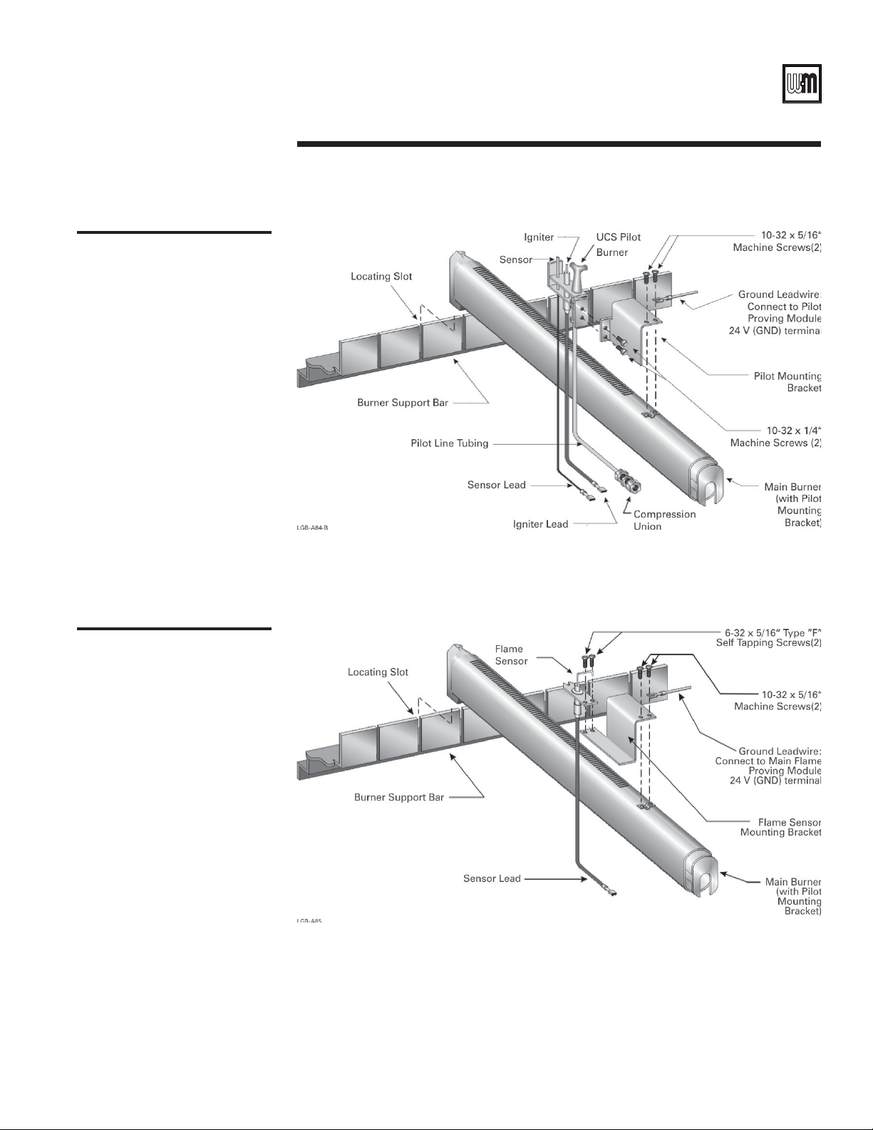
1. Assemble pilot burner and flame sensor to main burners with pilot brackets. See Figures 1
and 2 (page 3). Install ground wiring as shown in Figures 1 and 2 (page 3).
2. Reinstall burner assemblies. See Table 1, below for pilot burner and flame sensor locations.
3. Install gas controls and ignition control panel as shown in Table 2, below and Figure 5 on
page 10.
4. LGB-21 through LGB-23 require High Gas Pressure Switch Control Carton - 7" and 5" W.C.
Attach pressure switch to interior jacket panel. See Figure 5 on page 10.
5. Canada only - mount rating plate on interior jacket panel.
Series 2 – Control Supplement
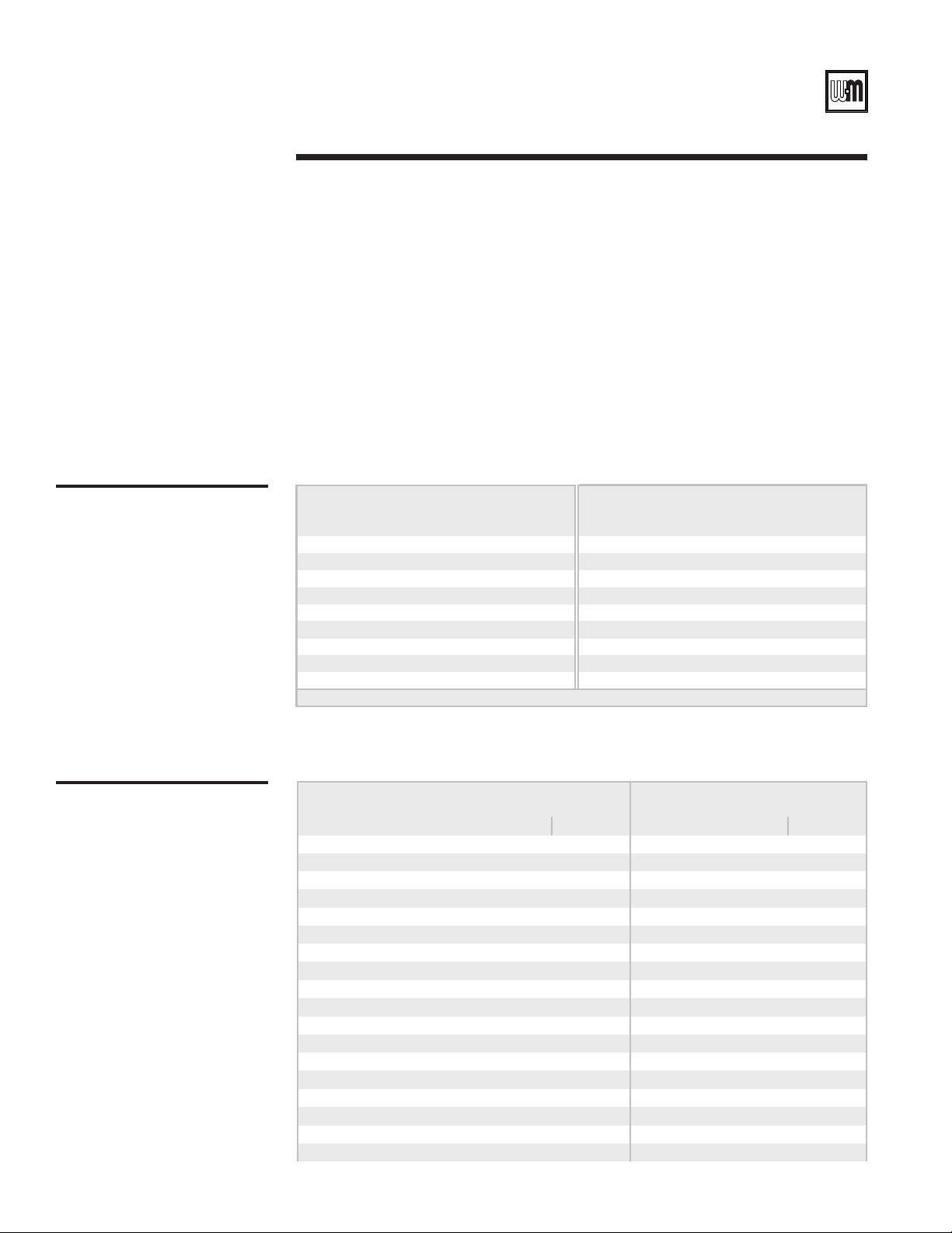
Table 1
Pilot burner and flame sensor
locations
Table 2
Gas control arrangement
Boiler
Model
Number
LGB-6 2--9--LGB-15 2161327
LGB-7 2--11--LGB-16 2181529
LGB-8 2--13--LGB-17 2181531
LGB-9 2--15--LGB-18 2201633
LGB-10 2--16--LGB-19 2201634
LGB-11 2--16--LGB-20 2221636
LGB-12 2--16--LGB-21 2221636
LGB-13 2141123LGB-22 2241638
LGB-14 2161325LGB-23 2241638
* From le f t burner
Boiler
Model
Number
LGB-6 A and B 1" -- A and B 1 ¼" --
LGB-7 A and B 1" -- A and B 1 ¼" --
LGB-8 C and D 1" -- C and D 1 ¼" --
LGB-9 C and D 1" -- C and D 1 ¼" --
LGB-10 E, F and G 1 ¼" -- E 1 ½" --
LGB-11 E, F and G 1 ¼" -- F and G 2" --
LGB-12 E, F and G 1 ¼" -- F and G 2" --
LGB-13 H 1"1"H1 ¼"1 ¼"
LGB-14 I 1"1"I 1 ¼"1 ¼"
LGB-15 J 1"1"J 1 ¼"1 ¼"
LGB-16 J 1"1"J 1 ¼"1 ¼"
LGB-17 J 1"1"J 1 ¼"1 ¼"
LGB-18 K 1 ¼" 1" K 1 ½" 1 ¼"
LGB-19 L 1 ¼" 1 ¼" M 1 ½" 1 ½"
LGB-20 L 1 ¼" 1 ¼" N 2" 1 ½"
LGB-21 L1 ¼"1 ¼"O2"2"
LGB-22 L1 ¼"1 ¼"O2"2"
LGB-23 L1 ¼"1 ¼"O2"2"
Flame Sensor* Pilot Burner*
No. 1 No. 2 No. 1 No. 2 No. 1 No. 2 No. 1 No. 2
7"
W.C.
Carton
Inlet Pipe Size
Left base Right base Left base Right base
Boiler
Model
Number
Flame Sensor* Pilot Burner*
5"
W.C.
Carton
Inlet Pipe Size
2
Part Number 550-141-916/0304
Page 3
I Installation – continued
Figure 1
Pilot burner assembly, typical
Universal Control System – Natural gas
Figure 2
Main flame sensor assembly
Part Number 550-141-916/0304 3
Page 4
LGB-6 to LGB-23
II Gas piping
1. Size gas piping considering —
a. Diameter and length of gas supply piping.
b. Number of fittings.
c. Maximum gas consumption (including any possible future expansion).
d. Allowable pressure drop from gas meter outlet to boiler. For pressure drops, see
ANSI-Z223.1 – latest edition. Canadian installations must comply with B149.1 or
B149.2 Installation Code.
2. Size natural gas piping from Table 3, below. Size piping to provide proper inlet pressure to
gas valve when operating at rated input.
a. Inlet gas pressure to manual main shut-off gas valve —
minimum 7" W.C. standard (5" on special order) – maximum 13" W.C.
b. If pressure to gas valve exceeds 13" W.C., install positive dead-end lockup gas pressure
regulator upstream of hand valve.
c. To obtain approximate cubic feet per hour, divide input (BTU/HR) by 1000.
3. Remove gas supply knockout disc from jacket panel.
4. Follow good piping practices.
5. Pipe joint compound (pipe dope) must be resistant to corrosive action of liquefied
petroleum gases. Apply sparingly only to male threads of pipe joints.
6. Install drip leg at inlet of gas connection to boiler. Where local utility requires, extend drip
leg to floor.
7. Install ground joint union when required for servicing.
8. Support piping by hangers, not by boiler or its accessories.
9. Purge all air from supply piping.
10. Before operating boiler, check boiler and its gas connections for leaks.
Do not check for gas leaks with an open flame – BUBBLE TEST. Failure to
use bubble test or test for leaks can cause severe personal injury, death or
substantial property damage.
a. Close manual main shut-off valve during any pressure testing at less than 13" W.C.
b. Disconnect boiler and gas controls from gas supply piping during any pressure test
greater than 13" W.C.
11. Set gas pressure switch as follows or to local inspector’s requirements (LGB-21 through
LGB-23 only):
a. High – 14" W.C.
12. Canada only - manual main shut-off valve must be identified by installer.
Series 2 – Control Supplement
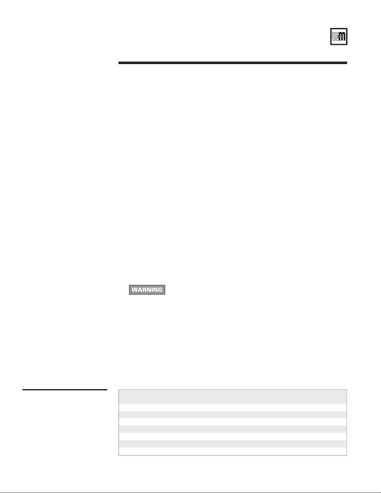
Table 3
Natural gas supply pipe sizing
4
Pipe
Size
1 ¼" 1,050 730 590 500 440 360 305 250
1 ½" 1,600 1,100 890 760 670 545 460 380
2" 3,050 2,100 1,650 1,450 1,270 1,020 870 710
2 ½" 4,800 3,300 2,700 2,300 2,000 1,650 1,400 1,130
3" 8,500 5,900 4,700 4,100 3,600 2,900 2,500 2,000
4" 17,500 12,000 9,700 8,300 7,400 6,000 5,100 4,100
*Include measured length of gas supply piping and allowance in feet for number and size of fittings.
*Pipe length, in feet (Natural Gas capacities, listed in MBH)
10 20 30 40 50 75 100 150
Part Number 550-141-916/0304
Page 5

Universal Control System – Natural gas
III Wiring
1. All wiring must be installed in accordance with the requirements of the National Electrical
Code and any additional national, state or local code requirements having jurisdiction. All
wiring must be N.E.C. Class 1.
2. The boiler must be electrically grounded in accordance with the National Electrical Code,
ANSI/NFPA No. 70-latest edition. Use 105 °C. thermoplastic wire, or equivalent, if any of
the original wire must be replaced (except for pilot spark, sense and ground wires).
3. Canadian installations must conform to CSA C22.1 Canadian Electrical Code Part 1 and
any local or provincial codes.
4. Supply wiring to the boiler must be No. 14 gauge or heavier. Install in conduit.
5. A separate electrical circuit with a fused disconnect switch (15 amp. recommended) should
be used for the boiler.
For your safety, turn off electrical power supply before making any electrical
connections to avoid possible electrical shock hazard.
Sequence of operation
1. Operating control begins start-up sequence.
a. Limit control contacts are closed.
2. Pilot-proving module energized.
On failure to sense pilot flame or main flame, control will wait 5 minutes
then retry for ignition.
a. Pilot solenoid opens.
b. Pilot ignition spark begins.
c. Pilot ignites.
d. Pilot proves.
3. Main flame-proving module energized from pilot-proving module.
a. Secondary gas valve opens.
b. Main gas valve opens to low fire position.
c. Main burners ignite at low fire.
d. Main flame sensor proves low fire carryover.
e. Main gas valve opens to high fire position.
f. Main burners increase to high fire.
4. Dual base assembly (LGB-13 through LGB-23) - operating control energizes controls for
both base assemblies at the same time. See steps 1 through 3 above.
5. Boiler shuts down when operating control is satisfied.
Part Number 550-141-916/0304 5
Page 6

LGB-6 to LGB-23
III Wiring – continued
Series 2 – Control Supplement
6
Part Number 550-141-916/0304
Page 7

Universal Control System – Natural gas
Figure 3
Wiring diagram
Part Number 550-141-916/0304 7
Page 8

LGB-6 to LGB-23
III Wiring – continued
Series 2 – Control Supplement
Wiring Procedure
1. Determine right or left electrical supply wiring.
2. Attach electrical junction box(es) to inside jacket end panel. Screws and nuts are provided.
For dual base boilers, use offset nipples (provided) to connect junction boxes together,
then hang junction boxes by screwing top box to boiler jacket. See Figure 4, below.
3. Attach control transformer(s) to junction box(es).
4. Drill 1/8" hole in interior jacket panel midway between ignition control panel and left jacket
panel. Mount wire support clip using sheet metal screw (furnished).
5. Complete wiring per wiring diagram, Figure 3 (pages 6 and 7).
“Hot” side of line voltage to boiler must be wired directly to limit circuit,
then fed to transformer primary(ies). Dual Base: “R” terminal of
secondaries are to supply power to bases independently of each other. Do
not wire “R” terminals together.
6. Install pilot proving and main flame proving ground connections as shown in Figures 1
and 2 (page 3) and Figure 3 (pages 6 and 7). Route wires through wire support clip.
7. Canada only - attach chain between junction box(es) and transformer with S-hooks.
Figure 4
Junction box assembly
dual base boilers
8
Part Number 550-141-916/0304
Page 9

Universal Control System – Natural gas
IV Operating instructions
Part Number 550-141-916/0304 9
Page 10

LGB-6 to LGB-23
Series 2 – Control Supplement
V Verification testing
Before starting boiler for the first time and at least annually (during annual inspection and
start-up), follow the procedures below to verify boiler controls are operating correctly and
that automatic gas valve properly shuts off gas flow. Failure to verify boiler operation
could result in severe personal injury, death or substantial property damage.
Manual test firing
valve
Verify boiler control
sequence
Leak test automatic
gas valve
This boiler is equipped with a manual test firing valve — the manual gas valve piped
between the gas manifold and the first automatic gas valve in the gas train. Closing the
manual test firing valve allows verification of proper boiler operation without allowing
gas flow to the manifold and allows leak testing of the automatic gas valves. Follow the
procedures below.
1. Follow the Operating Instructions in this Supplement to start the boiler, but do not
open the manual test firing valve
Leave the manual test firing valve closed.
2. The automatic pilot burner should light.
3. After the pilot lights, the boiler controls should activate the automatic gas valves. Use a
voltmeter to verify voltage to automatic valves.
4. With no gas flow to the manifold, the boiler ignition controls should turn off the
automatic gas valves after main flame ignition trial. Use a voltmeter to verify voltage to
automatic valves is turned off.
1. Close manual test firing valve.
2. Open the service valve and gas hand valve.
3. Install a hose barb into a pressure tap downstream of the first automatic gas valve.
Allow any accumulated gas in the line to vent off. Then connect a U-tube manometer.
If the valve seals properly, there should be no gas pressure present. Remove manometer
and hose barb and replace pipe plug in pressure tap.
4. Connect the manometer downstream of the second automatic gas valve. Temporarily
remove the power leads to the first automatic gas valve. Then connect 24 volt power to
the first automatic gas valve terminals to open it. If the second valve seals properly,
there should be no pressure at the manometer.
5. Remove the temporary power supply to the automatic gas valve. Reconnect its power
leads. Remove the manometer and plug any open pressure taps.
6. Follow Operating Instructions to place boiler in service.
. Open all other manual gas valves as instructed.
10
Replace any defective components. Do not attempt to operate boiler or leave boiler in
operation if any component is found to be defective or to operate incorrectly. Failure to
comply could result in severe personal injury, death, or substantial property damage.
Part Number 550-141-916/0304
Page 11

Universal Control System – Natural gas
VI Parts list – continued
Figure 5
Parts
drawing
Part Number 550-141-916/0304 11
Page 12

LGB-6 to LGB-23
Series 2 – Control Supplement
12
Weil-McLain
500 Blaine Street
Michigan City, IN 46360-2388
http://www.weil-mclain.com
Part Number 550-141-916/0304
 Loading...