

Page 1

Ncstudio
PC-BASED NUMERIC CONTROLLER
PROGRAMMING MANUAL
Where there is motion control
there is WEIHONG
Page 2

上海维宏电子科技股份有限公司
Weihong Electronic Technology Co., Ltd.
Thank you for choosing our products!
This manual will help you acquaint with our products and learn the information about
programming command system.
This manual makes a detailed introduction to the thought of system software programming and
the command system of programming, as well as to system software support of PLT, CAM, and DXF.
Before using the products and relative machine equipment, carefully read this manual to have a better
use of them.
Because of continuous update in hardware and software, it is possible that the software and the
hardware you have received differ from the statement in this manual.
Company address, phone number and our website are listed here for your convenience. Any
questions, please feel free to contact us. We will always be here and welcome you.
Company Name: Weihong Electronic Technology Co., Ltd.
Company Address: No. 29, 2338 Duhui Rd., Minhang, Shanghai
Zip Code: 201108
Tel: +86-21-33587550
Fax: +86-21-33587519
Website: http://en.weihong.com.cn
Specialized, Concentrated, Focused i
Page 3

上海维宏电子科技股份有限公司
Weihong Electronic Technology Co., Ltd.
Contents
1 New Functions ........................................................................................................................... 1
2 Summarization of CNC Programming ..................................................................................... 2
2.1 Summarization of CNC Programming .................................................................................... 2
2.2 Summarization of CNC Machine Tool ..................................................................................... 2
3 Structure of Machining File ...................................................................................................... 5
3.1 Address Symbols and Functions ............................................................................................ 5
3.2 Format of Program Block ........................................................................................................ 6
3.3 Format of Subprogram ............................................................................................................ 6
4 Programming Instruction System ............................................................................................ 7
4.1 Spindle Function (S), Feed Function (F) &Tool Function (T) .................................................. 7
4.2 Miscellaneous Function M Code............................................................................................. 8
4.3 Preparatory Function G Code ................................................................................................. 8
4.4 Advanced Functions.............................................................................................................. 51
4.5 Expressions Used in Program Instructions........................................................................... 55
4.6 Comments in Program .......................................................................................................... 56
4.7 Demonstration of Machining File Programming ................................................................... 56
4.8 G Command Appendix .......................................................................................................... 61
5 Named Parameters .................................................................................................................. 63
6 Customize and Extend Command M ..................................................................................... 68
7 PLT Support.............................................................................................................................. 69
8 DXF Support ............................................................................................................................. 70
ii Specialized, Concentrated, Focused
Page 4

上海维宏电子科技股份有限公司
Weihong Electronic Technology Co., Ltd.
1 New Functions
1) New command M802 P458752 is used for clearing the external offset. For detailed
information please refer to chapter 4.4.
2) New command G921 is used for specifying the workpiece coordinates of current point in the
current coordinate system. For detailed introduction please turn to chapter 4.3 ―commands
related to coordinate system and coordinates‖.
3) New command G922 is used for setting the machine coordinate of the origin of the specified
workpiece coordinate system. For detailed introduction please refer to chapter 4.3
―commands related to coordinate system and coordinates‖.
4) New support for circle, bias and chessboard drilling cycle command (G34, G35, G36, and
G37). For detailed introduction please refer to chapter 4.3 ―special canned cycle‖.
5) New rotation function commands G68/G69, for detailed introduction please refer to chapter
4.3 ―G68/ G69 coordinate system rotation function commands‖.
6) New mirror image function commands G50.1/G51.1, for detailed introduction please refer to
chapter 4.3 ―G50.1/ G51.1 mirror image function commands‖.
7) New command G923 is used for direct tool offset setting, for detailed introduction please
refer to chapter 4.3 ―G923 directly set tool offset‖.
8) Strengthened function for command G906 to test if the specified port is timeout. For detailed
introduction please refer to chapter 4.4.
9) New command M903 is used for modifying the current tool number. For detailed introduction
please refer to command M list in chapter 4.4.
10) Command G92 is taken as invalid command in the array machining, and should be deleted
manually. For detailed introduction please refer to chapter 4.3, ―commands related to
coordinate system and coordinates‖.
11) Refer to chapter 4.4 for new function of naming a subprogram.
12) Improvement of command G904: the usage of PLC address; keywords of PX, PY, PZ are
compatible with PLC address and equal mark expression.
13) Improvement of M901 and G906: the usage of PLC address; new keywords ―PLC‖ and
―LEVEL‖; and PLC keywords are compatible with [PLC address] and equal mark expression.
14) New command G992 allows the translation of coordinate system. For detailed introduction
please refer to ―G992 temporarily set WCS according to tool position‖ in chapter 4.3.
15) New command G28 is used for backing to the reference point. For detailed introduction
please refer to chapter 4.3, ―G28 auto back to reference position‖.
16) New commands related with encoder. For details, refer to ―G codes related with encoder‖ in
chapter 4.3.
Specialized, Concentrated, Focused 1
Page 5
上海维宏电子科技股份有限公司
Weihong Electronic Technology Co., Ltd.
2 Summarization of CNC Programming
2.1 Summarization of CNC Programming
Definition of Machining File
Composed of a series of instructions written in a programming language which is specially used
for CNC device, a machining file will be translated into motion actions to control the machine tool by
CNC device. The most commonly used storage mediums are punched tape and disk.
Creation of Machining File
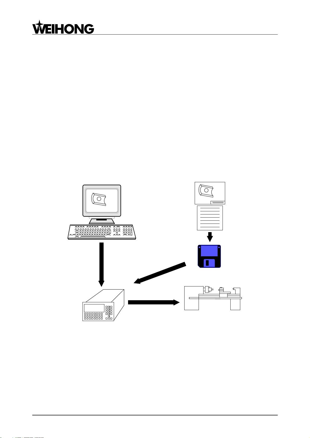
As shown in Fig. 2-1 below, a machining file can be created by traditional manual programming
or CAD/CAM application (Such as the popular MasterCAM application).
Fig. 2-1 Creation of a Machining File
2.2 Summarization of CNC Machine Tool
Machine Tool Coordinate Axes
To simplify programming and guarantee the generality of program, this manual has standardized
the naming of coordinate axes and the direction of CNC machine tool. Linear feeding coordinate axes
2 Specialized, Concentrated, Focused
Page 6
上海维宏电子科技股份有限公司
+Y
+X
+Z
+Y
+C
+A
+B
+Z
+X
+Y
+X
+Z
+X+Y+Z
+A+B
+C
Weihong Electronic Technology Co., Ltd.
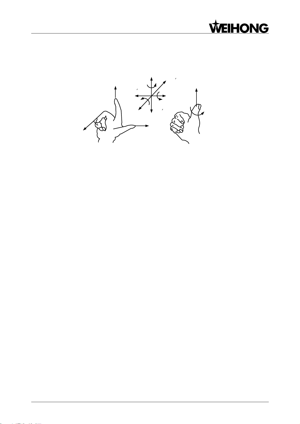
are denoted by X, Y and Z, which are normally referred as basic coordinate axes. The correlation of X,
Y and Z axes follows ―the Right Hand Rule‖, as shown in Fig. 2-2. The thumb points in the +X
direction, the index finger points in the +Y direction, and the middle finger points in the +Z direction.
Fig. 2-2 Machine Tool Coordinate Axes
Circle feed coordinate axes swiveling around X, Y and Z are respectively denoted by A, B, and C.
According to the Right Hand Screw Rule, the thumb points in +X, +Y and +Z direction, while the index
and middle finger points in +A, +B, and +C direction of circle feed motion. The feed motion of CNC
machine can be realized by spindle driving the tool or the worktable driving the workpiece. The
positive directions of coordinate axes mentioned above are directions of tool feeding relative to the
supposedly stationary workpiece. If the workpiece is kinetic, the coordinate axes are marked with ―’‖.
According to relative motion, the positive direction of workpiece movement is opposite to that of tool
movement, that is:
+X =-X’, +Y =-Y’, +Z =-Z’
+A =-A’, +B =-B’, +C =-C’
Likewise, their negative directions are contrary to each other.
The directions of machine coordinate axes depend on the type of machine tool and the layout of
each component. For a milling machine:
Z: Z-axis coincides with the main spindle axis, and the direction of tool moving away from
workpiece is the positive direction (+Z);
X: X-axis is perpendicular to Z-axis and parallel to the clamped surface of workpiece. For a single
column vertical mill, if the user faces the spindle and looks in the column direction, right moving
direction is the positive direction of X-axis (+X);
Y: Y-axis, X-axis and Z-axis together constitute a coordinate system abiding by right hand rule.
Specialized, Concentrated, Focused 3
Page 7
上海维宏电子科技股份有限公司
Mechanical Stroke along X-axis (Limit)
Valid Stroke along X-axis
Valid Stroke along Y-axis
Mechanical Stroke along Y-axis
Y
O m
O M
X
Weihong Electronic Technology Co., Ltd.
Machine Origin (MO) and Machine Reference Point (REFER) of
Machine Coordinate System (MCS)
MCS is the intrinsic coordinate system of machine tool. Known as machine origin or machine
zero point, or home position, the origin of MCS is confirmed and fixed after designing, manufacturing
and tuning of machine. The CNC device doesn’t know where machine origin is when power on, and
the mechanical stroke of each coordinate axis is limited by maximum and minimum limit switch. To
correctly set MCS at machining, we normally set a machine REFER point (the initial point of
measurement) within the stroke range of each coordinate axis. After starting the machine, it is
necessary to back to REFER point manually or automatically so as to create the MCS. The REFER
point can coincide with MO or not. If not, the distance from machine REFER point to MO can be set by
parameter setting. After the machine returns to the REFER point, the machine origin, which is the
reference point of all coordinate axes, is confirmed, so the MCS is established. The stroke of MCS is
defined by the machine tool manufacturer, while the valid stroke of MCS is defined by software limit.
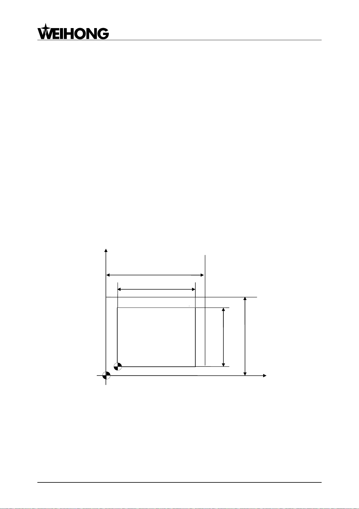
The relationship between machine origin (OM), machine REFER point (Om), the mechanical stroke
and valid stroke of MCS is as shown in Fig. 2-3.
Fig. 2-3 Machine Origin OM and Machine REFER Om
4 Specialized, Concentrated, Focused
Page 8
上海维宏电子科技股份有限公司
N01 G91 G00 X50 Y60
N10 G01 X100 Y500 F150 S300 M03
N……
N200 M02
Program
block
Command
word
Address
Symbol
Description
B: Basic Function
O: Optional Function
D
Cutter radius offset number
B, O
F
Feedrate function
B
G
Preparatory commands
B, O
H
Tool length offset
B I Arc center modifier for X axis
B, O
J
Arc center modifier for Y axis
B, O
K
Arc center modifier for Z axis
B L Repetition count
B, O
M
Miscellaneous function
B N Sequence no. or block no.
B
O
Program no.
B
P
Dwell time in milliseconds, subprogram no.
call, custom macro no. call, block number in
main program when used with M99
O, B
Q
Depth of peck in fixed cycles G73 and G83
Shift amount in fixed cycle G76 and G87
O
R
Retract point in fixed cycles
O, B
Weihong Electronic Technology Co., Ltd.
3 Structure of Machining File
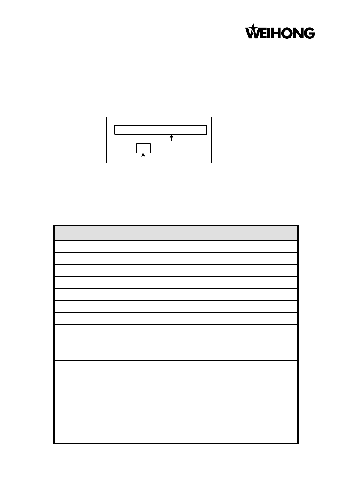
A machining file is a group of instructions and data transmitted to the CNC device, and it is
composed of program blocks which follow a certain structure, syntax and format rule, while each
program block is composed of command words. See Fig. 3-1.
Fig. 3-1 Program Structure
3.1 Address Symbols and Functions
Address symbols and definitions are as shown in Form 3-1.
Form 3-1 Address Symbols
Specialized, Concentrated, Focused 5
Page 9
上海维宏电子科技股份有限公司
Address
Symbol
Description
B: Basic Function
O: Optional Function
Arc radius designation
S
Spindle speed in r/min
B T Tool function
B X X axis coordinate value designation
B Y Y axis coordinate value designation
B
Z
Z axis coordinate value designation
B
N.. G.. X.. F.. M.. S..
Program Block No.
Preparatory F.
Dimension W.
Feed F.W.
Miscellaneous F.W.
Spindle F.W.
F.: Function
W.: Word
Program Block
Weihong Electronic Technology Co., Ltd.
3.2 Format of Program Block
A program block defines a line of instructions to be executed by CNC device. The format of
program block defines the syntax of function word in each program block, as shown in Fig. 3-2.
Fig. 3-2 Format of Program Block
3.3 Format of Subprogram
A subprogram is a section of machining codes which can be called repeatedly. It must begin with
the address word O and subprogram no. as the first line and end with M17 as the last line. On
principle, commands like M30 and M17 are not allowed to appear among the subprogram, but nested
subprogram is acceptable.
6 Specialized, Concentrated, Focused
Page 10

上海维宏电子科技股份有限公司
Weihong Electronic Technology Co., Ltd.
4 Programming Instruction System
4.1 Spindle Function (S), Feed Function (F) &Tool Function (T)
Spindle Function S
Command Format: S_
Description:
S command is used to control the spindle speed. Its subsequent numerical value denotes the
rotate speed of spindle in rpm.
S is a modal command, and S function is valid only when the spindle speed is adjustable. When
one S command is specified, it will be valid until the next S command is specified.
Note: even though the spindle is off, the value of S remains.
Feed Speed (Feedrate) F
Command Format: F_
Description:
Command F indicates the synthetic feed speed of tool relative to the workpiece being machined.
Its unit is mm/min.
With the help of feedrate override switch on the operation panel, F can be adjusted between
feedrate percent 0% -120%.
F functions differently with different commands:
G00 command, specifying the rapid traverse speed, modal for the current machining procedure.
G01~G03 command, specifying the feed speed, modal for the current machining procedure.
Tool Function (T Feature)
Command Format: T_
Description:
T is used for selecting a tool; the subsequent value denotes the tool no. selected, and the
relationship between T code and a tool is stipulated by machine tool manufacturer.
When a machining center runs T code, tool magazine will rotate to select the required tool, and
wait until command M06 comes into effect to finish automatic tool change.
T command calls in tool compensation value (including length and radius) from the tool
Specialized, Concentrated, Focused 7
Page 11
上海维宏电子科技股份有限公司
M Code
Meaning
M Code
Meaning
M00
Compulsory program stop
M11
Spindle unclamp
M01
Optional program stop
M17
Subprogram return
M02
End of the program
M30
End of program, and return to program top
M03
Spindle on (CW rotation)
M98
Subprogram call
M04
Spindle on (CCW rotation)
M99
End of subprogram, and return to the
beginning of main program for continuous
execution
M05
Spindle stop
M801
String info transmission between modules
M06
Automatic tool change
(ATC)
M802
Integer info transmission between modules
M08
Coolant on
M901
Directly control output port
M09
Coolant off
M902
Directly set REF.
M10
Spindle clamp
M903
Change current tool no.
Weihong Electronic Technology Co., Ltd.
compensation register. Although T command is a non-modal instruction, the value of tool
compensation invoked is effective until a new value is invoked for the next tool change.
4.2 Miscellaneous Function M Code
Miscellaneous function is composed of address word M and its subsequent number of one to
three digits. It is mainly used to control the running of machining file and on/off of machine
miscellaneous functions.
M function has non-modal and modal forms:
Non-modal M function: it is effective only in the program block containing it.
Modal M function: a group of M functions that can be mutually cancelled; an M function remains in
effect until another M function in the same group appears to cancel it.
Form 4-1 Miscellaneous Function M Code
4.3 Preparatory Function G Code
Preparatory function G code is composed of address word G and its subsequent 1-3 digits. It is
used to specify machining operations, such as the moving track of tool relative to workpiece, machine
coordinate system, coordinate plane, tool compensation, coordinate offset, subprogram call, dwell,
and so on.
G function has two forms, which are non-modal and modal G function:
Non-modal G function: only effective in the specified program block, and cancelled at the end of
program block.
8 Specialized, Concentrated, Focused
Page 12
上海维宏电子科技股份有限公司
206040
Y
X
O
15
25
45
1
2
3
N X Y
N01 X20 Y15
N02 X40 Y45
N03 X60 Y25
N X Y
N01 X20 Y15
N02 X20 Y30
N03 X20 Y-20
G90 programming G91 programming
Weihong Electronic Technology Co., Ltd.
Modal G function: a group of G functions that can be cancelled mutually; a G function remains in
effect until another G function in the same group appears to cancel it.
Commands Related to Coordinate System and Coordinates
G90 Absolute Programming and G91 Incremental Programming
Command Format: G90/G91
Description:
G90: it denotes absolute programming; the programming value on each programming coordinate
axis is with respect to the origin of current WCS.
G91: it denotes incremental programming; the programming value on each programming
coordinate axis is with respect to the previous position, and the value equals the distance that the tool
moves in each axis.
G90, as the default, and G91 are modal functions and can be mutually cancelled. They cannot be
used in the same program block. For example, G90 G91 G0 X10 is unallowable.
Programming Example:
As shown in Fig. 4-1 below, programming with G90, G91: the tool moves in sequence from origin
to point 1, 2, and 3.
Fig. 4-1 G90/G91 Programming
Selecting the right mode can simplify the programming. If the drawing dimension is given based
on a fixed datum, it is better to adopt absolute programming mode; if the drawing dimension is given
on the basis of space distance between contour apexes, it is better to adopt incremental programming
mode.
G92 Set WCS according to Tool Position
Command Format: G92 X_Y_Z_
Description:
X_Y_Z_: the directed distance between origin of WCS and the beginning point of tool, i.e. the
workpiece coordinates of the beginning point of current tool
A program is compiled based on WCS and begins with the cutter beginning point; before
Specialized, Concentrated, Focused 9
Page 13
上海维宏电子科技股份有限公司
Program Zero
30.0
Y
X
30.0
Tool initial point
20.0
Z
G92 X30.0 Y30.0 Z20.0
Weihong Electronic Technology Co., Ltd.
machining, the WCS should be learnt by the CNC system so as to link up the WCS with the MCS by
setting the coordinates of cutter beginning point in the MCS.
G92 command can set the REFER point; it can also create a WCS by setting the relative position
of tool beginning point (tool measurement point) to origin of WCS to be created. Once the WCS is
established, the value of the command in absolute programming is the coordinate value in the WCS.
Fig. 4-2 Creation of Workpiece Coordinate System
Programming Example:
Programming with G92 command to create a WCS is as shown in Fig. 4-2.
The execution of the program block only creates a WCS without cutter movement. As a
non-modal command, G92 is usually put in the first block of machining file to create a WCS and
synchronously offset origins of other WCSs, which can be used to adjust the length of cutter holder.
G921 Specify Work Coordinate Value of Current Point
Command Format: G921 X_Y_Z_
Description:
X_Y_Z_: workpiece coordinates of the current point
G921 is used to set workpiece coordinates of current point in the current WCS; unlisted axes will
not be modified; this setting has effect only on the current WCS.
G921 command can be used for measuring workpiece surface, center or boundary.
G922 Specify the Machine Coordinates of WCS Origin
Command Format: G922 X_Y_Z_P_
Description:
X_Y_Z_: offset values
P_: specifying offset type. -4: external offset; -1: current WCS (default); 0~5: corresponding to
G54~G59
G922 sets the coordinate value of the specified offset, without changing unlisted axes’ offset.
G922 command can be used for measuring workpiece surface, center or boundary.
10 Specialized, Concentrated, Focused
Page 14

上海维宏电子科技股份有限公司
A (0, 0, 10), target position, X and Y
back to origin, Z-axis keeps still.
Instruction: G28 X100 Y50
The machine Tool moves from
point C (current position) to
point A (machine origin) via
point B (middle point). Since Z
axis does not appear, Z axis
keeps still without returning to
zero.
C (40, 90, 10)
current position
B (100, 50, 10)
middle point
Weihong Electronic Technology Co., Ltd.
G28 Auto Back to Reference Position
Command Format: G28 X_Y_Z_
Description:
X_Y_Z_: coordinates of the middle position (Workpiece Coordinates)
A machine tool returns to REFER point (machine origin) through the middle point, as shown in
Fig. 4-3.
Fig. 4-3 Back to Reference Position
G992 Temporarily Set WCS according to Tool Position
Command Format: G992 X_Y_Z_ /I_J_K_
Description:
The function of this command is similar to G92 command. Their difference is: G92 command
alters the WCS permanently and takes the same standard to the whole system, while G992 command
alters the WCS temporarily and only influences the coordinate parsing of processing instruction,
which will be restored automatically at the end of machining.
The command can be used for implementing array function. The steps are as shown below.
Method one:
G992 X_Y_Z_
1. Delete M30 command in the processing file.
2. Adding the following contents at the beginning of the processing file:
#1=30 ’X offset value
#2=40 ’Y offset value
#3=30 ’machining quantity along X axis
#4=30 ’machining quantity along Y axis
G65 P3455 L=#4
G00 G90 X=-#1*#3 Y=-#2*#4
G992 X0 Y0
M30
O3455
G65 P3456 L=#3
G00 G90 X=-#1*#3 Y=#2
G906
Specialized, Concentrated, Focused 11
Page 15

Weihong Electronic Technology Co., Ltd.
G992 X0 Y0
M17
O3456
3. Add the following contents at the end of the processing file:
G00 G90 X=#1
G906
G992 X0
M17
Method two:
G992 I_J_K
1. Delete M30 command in the processing file.
2. Add the following contents at the beginning of the processing file:
#1=30 ’X offset value
#2=40 ’Y offset value
#3=30 ’machining quantity along X axis
#4=30 ’machining quantity along Y axis
G65 P3455 L=#4
G00 G90 X=-#1*#3 Y=-#2*#4
G992 I=-#1*#3 J=-#2*#4
M30
O3455
G65 P3456 L=#3
G00 G90 X=-#1*#3 Y=#2
G906
G992 I=-#1*#3 J=#2
M17
O3456
3. Add the following contents at the end of the processing file:
G00 G90 X=#1
G906
G992 I=#1
M17
上海维宏电子科技股份有限公司
Both the above two programs can realize the related array machining. The first 4 parameters can
be adjusted and customized.
Note:
G992 X_Y_Z_ sets the current point as a specified point in the new coordinate system.
G992 I_J_K_ translates the original coordinate system a specified distance to form into a new
coordinate system. Comparatively speaking, G992 I_J_K_ is more efficient because it avoids the
redundant rapid traverse instruction produced by origin offset, while G992 X_Y_Z_ sets an origin after
backing to the original origin. During array machining, G92 command should be deleted manually
because it is not supported by the system.
12 Specialized, Concentrated, Focused
Page 16
上海维宏电子科技股份有限公司
G54 Origin
Workpiece
Origin Offset
Reference Point
(Machine Zero)
G59 Origin
G59 Workpiece
Coordinate System
G54 Workpiece
Coordinate System
Y
Z
X
X
Y
Z
N01 G54 G00 G90 X30 Y40
N02 G59
N03 G00 X30 Y30
...
Current Point A B
G59
Machine Origin
30
O
B
A
40
30
30
O
G59
X
Y
Y
X
Weihong Electronic Technology Co., Ltd.
G54~G59 WCS Selection
Command Format: G54/G55/G56/G57/G58/G59
Description:
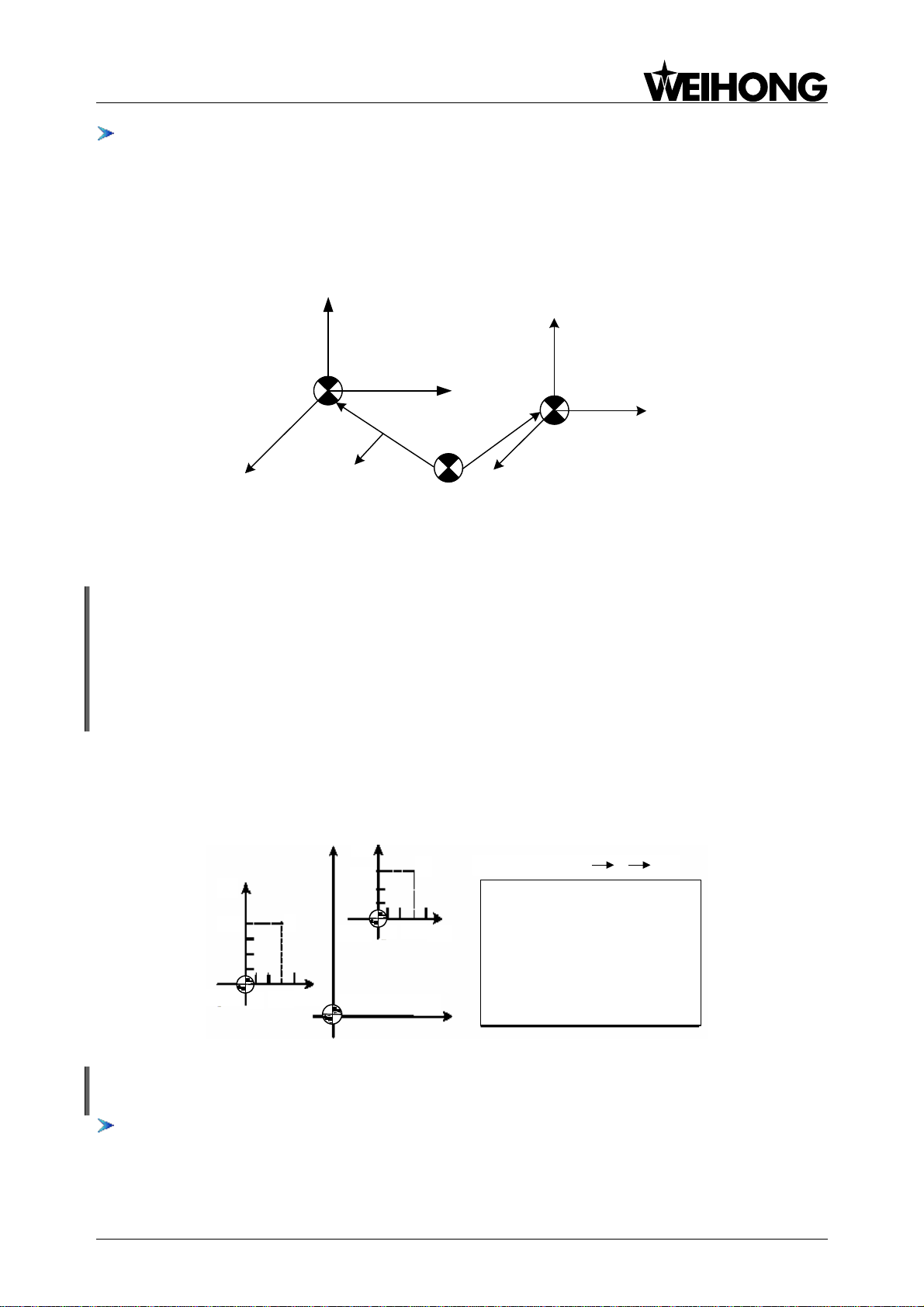
G54~G59 are 6 WCSs prepared by the system (as shown in Fig. 4-4). Any one of them can be
selected.
Fig. 4-4 Workpiece Coordinate System Selection (G54~G59)
The origin value of these 6 WCSs in the MCS (offset value of workpiece origin) can be set in the
[Param] setting interface. The setting value will be saved automatically by the controller.
Note:
Once a WCS is confirmed, the following instruction values in absolute programming are all relative to
the origin of WCS.
G54~G59 are modal functions, which can be mutually cancelled. G54 is the default.
Programming Example:
As shown in Fig. 4-5, programming based on WCS to make the tool move from current point to
point A, and then to point B.
Fig. 4-5 Programming Based on Workpiece Coordinate System
Set the coordinate value of each WCS origin in the MCS before using this group of instructions.
G53 Machine Coordinate System
Command Format: G53
Description:
Specialized, Concentrated, Focused 13
Page 17
上海维宏电子科技股份有限公司
X
Y
Z
G17
G18
G19
Weihong Electronic Technology Co., Ltd.
G53: using MCS and disabling zero offset of WCS. It is a non-modal instruction which is only
valid in the current program block.
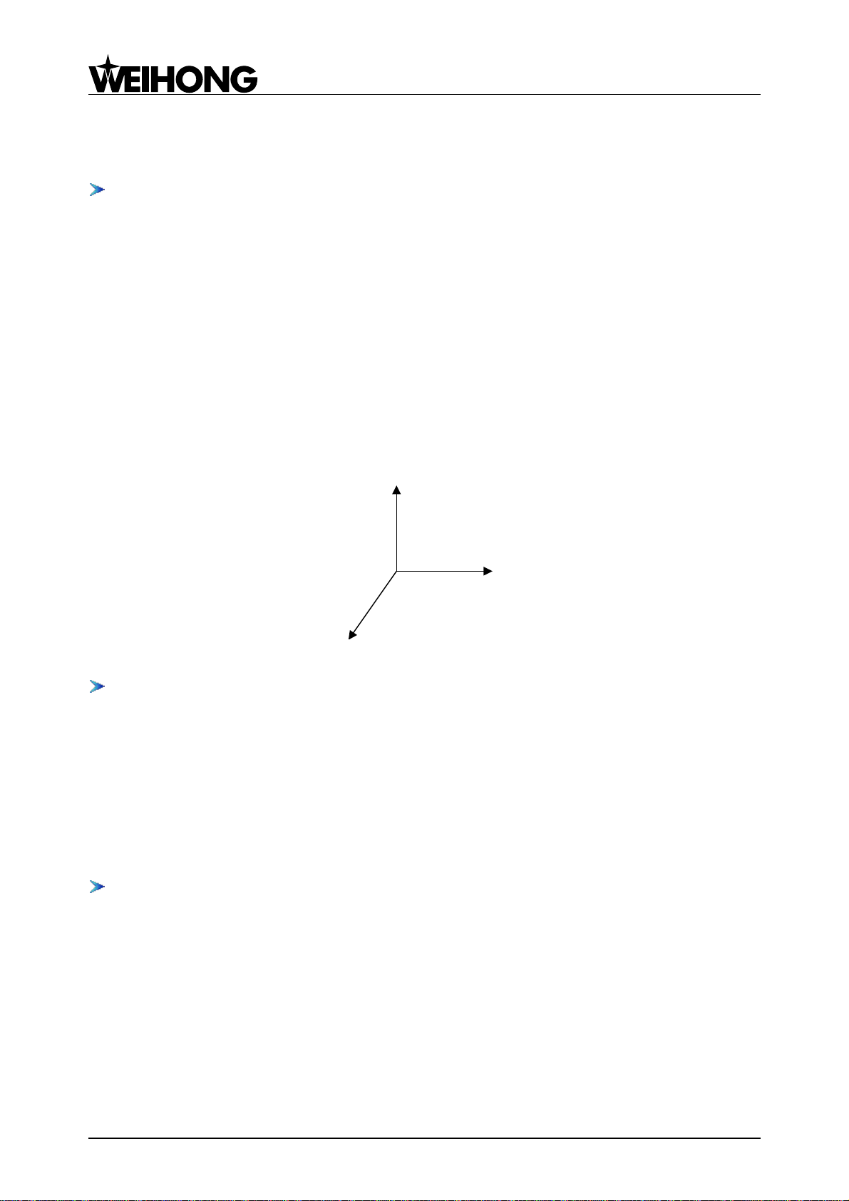
G17, G18, G19 Coordinate Plane Selection
Command format: G17/G18/G19
Description:
G17: XY plane selection
G18: ZX plane selection
G19: YZ plane selection
This group of instructions is used to select the plane to perform circular interpolation and cutter
radius compensation.
G17 (default), G18 and G19 are modal functions (as shown in Fig. 4-6), which can be mutually
cancelled.
Fig. 4-6 Coordinate Plane Selection
G20/G21 OR G70/G71 Inch/Metric Command
Command format: G20/G21/G70/G71
Description:
G20/70: inch
G21/71: metric
This group of G codes is defined at the beginning of the program block. If one of them is specified,
the units of all subsequent operations will be changed. If not specified, the default unit is metric.
G50/G51 Scaling Function
Command Format: G51 X_Y_Z_P_ (I_J_K_)
Description:
X_Y_Z_: the center of scaling. The omitted coordinate axes will inherit the original scaling and
remain the same.
I_J_K_: the scaling of X, Y and Z axes
P_: the scaling of all listed axes. Either P_ or I_J_K_ can appear in a program block.
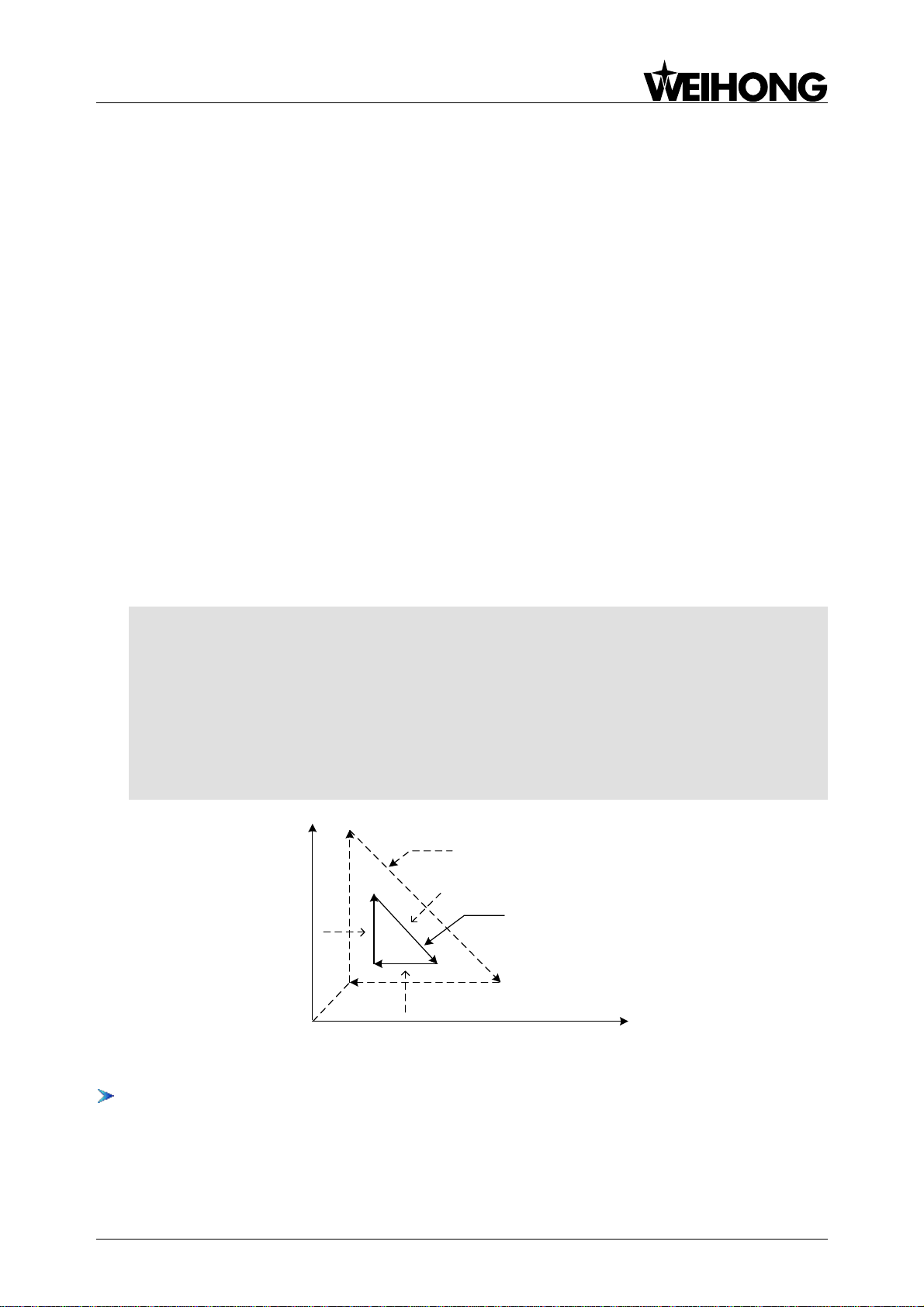
Workpiece contour that is compiled in the machining file can be reduced or enlarged to scale.
14 Specialized, Concentrated, Focused
Page 18
上海维宏电子科技股份有限公司
(50,150)
N07
(50,50) N05
N03
N04
Real path-after scaling
Program path-before scaling
(175,50)
Y
X
N01
Weihong Electronic Technology Co., Ltd.
G51 is scaling on, while G50 is scaling off (Default: G50).
The range of scaling: 0.000001-99.999999
For example:
I0.666666 denotes that X is scaled down to 0.666666 times of the original dimension, while J3
denotes that Y is scaled up to 3 times of the original dimension.
When using the scaling command, pay attention to the followings:
Don’t set the scale factor as 0, or else an alarm will appear.
Scaling function has no effect on compensation value.
When executing cutter radius compensation C, the scaling instruction (G51) can’t be specified.
A canned cycle cannot be executed together with the scaling of Z-axis. If so, an alarm will appear.
These G codes cannot be used in the execution process of scaling function: G28, G29, G53, and
G92, or else the outcome may contain an error.
If there is G51 in the program without G50, the scaling function will be automatically closed at the
end of the program.
Programming Example:
N01 G00 X50.0 Y50.0 ’rapid positioning
N02 G51 X100.0 Y80.0 P0.5 ’specifying X100, Y80 as the scaling center, and 0.5 as scale value
N03 G01 Y150.0 F1000 ’linear cutting with feed rate as 1000mm/min
N04 X175.0 Y50.0
N05 G90 X50.0
N06 G50 ’scaling function off
N07 G00 X0.0 Y0.0 ’returning rapidly
N08 M30 ’end of the program
Fig. 4-7 Sketch Map of Scaling Function
G68/G69 Coordinate System Rotation Function
Command Format:
G68 X_Y_Z_R_
G69
Specialized, Concentrated, Focused 15
Page 19
上海维宏电子科技股份有限公司
After Rotation
(100,50)
(100,0)
Before Rotation
(0,0)
(50,-100)(0,-100)
X
Y
Weihong Electronic Technology Co., Ltd.
Description:
X_Y_Z_: the center of rotation
R_: rotation angle in degree. Negative value is clockwise while positive value counterclockwise.
The instruction can be used for rotary contour machining by making the selected machining
contour rotates degrees specified by R around the center in the specified plane. G68 is rotation on,
while G69 rotation off.
Meaning of R: put a watch on the current plane, and let the watch surface towards the positive
direction of the third axis; positive means counterclockwise rotation, while negative clockwise rotation.
In the process of rotation, coordinate of the third axis perpendicular to the current plane is
constant. Respectively, swiveling in XY plane, the coordinate of Z-axis keeps still; swiveling in YZ
plane, the coordinate of X-axis keeps still; and swiveling in ZX plane, the coordinate of Y-axis keeps
still.
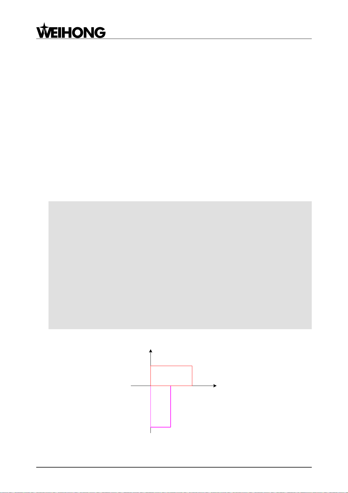
For example:
G17G90 X0Y0Z0
G65P9999L1
G68 X0Y0R-90 ’rotating 90 degrees clockwise around the center of (0, 0)
G65P9999L1
G69 ’rotation off
M30
O9999 ’machining a rectangle
G91 G1X100
Y50
X-100
Y-50
G90
M17
The actual outcome is as shown in Fig. 4-8:
16 Specialized, Concentrated, Focused
Fig. 4-8 Sketch Map of Rotation Processing
Page 20

上海维宏电子科技股份有限公司
Weihong Electronic Technology Co., Ltd.
The instruction can be nested:
G68 X_Y_Z_R_ ’………A
…
G68 X_Y_Z_R_ ’………B
…
G68 X_Y_Z_R_ ’………C
…
G69 ’………C’
G69 ’………B’
G69 ’………A’
Rotation that appears earlier will influence the following rotation instruction. The subsequent
rotation center is not the one in the machining file, but the position after transformation due to the
previous rotation.
The function of G69 is to cancel the previous rotation command. In the above-mentioned
program, line C’ cancels the G68 of line C, line B’ the G68 of line B, and line A’ the G68 of line A. If
G69 not used, all rotation commands will be automatically cancelled at the end of current machining.
The following example contains the nesting of rotation command and scaling command.
G90 G0 x0 y0 z0
G91G65 P9999 L1
G65 P9998 L10
M30
O9999
G1 x200
y-100
x-200
y100
M17
O9998
G68 x50 y50 R45
G65 P9999 L1
G51 x50 y50 p0.5
G65 P9999 L1
M17
The outcome is as shown in Fig. 4-9.
Specialized, Concentrated, Focused 17
Page 21
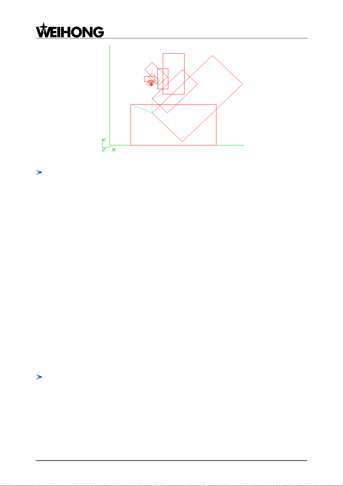
Fig. 4-9 Processing Outcome after Rotation
G50.1/G51.1 Mirror Image Function
Command Format:
G51.1 X_Y_Z_
上海维宏电子科技股份有限公司
Weihong Electronic Technology Co., Ltd.
G50.1 X_Y_Z_
Description:
X_Y_Z_: For G51.1, specifying mirror image center; for G50.1, specifying the invalid axes of
mirror image function.
The instruction indicates machining the mirror image of machining contour. G51.1 denotes mirror
image on and G50.1 off.
For G51.1, the center of mirror image can be a line, or a point. For example, G51.1 X10 specifies
the mirror image of the contour relative to the line X=10, while G51.1 X10 Y10 Z10 specifies the mirror
image of the contour relative to the point (10, 10, 10).
For G50.1, X_Y_Z_ is used to specify the invalid axes of mirror image function. For example,
G50.1 X0 closes the mirror image function of X-axis, and G50.1 Y0 Z0 closes the mirror image
functions of Y-axis and Z-axis. If X, Y and Z axes are all specified or no one is specified, it denotes the
mirror image functions of all the axes are closed.
Feed Control Commands
G00 Rapid Positioning
Command Format: G0 X_Y_Z_
Description:
G00: rapidly positioning the tool, but not causing any machining to the workpiece. It can
simultaneously perform rapid movement in several axes to produce a linear track. In the process of
instruction analysis, if there is motion in Z-axis, the motion can be resolved into Z-axis motion and
18 Specialized, Concentrated, Focused
Page 22

上海维宏电子科技股份有限公司
Weihong Electronic Technology Co., Ltd.
plane motion to ensure safe movement. For Z-axis upward motion, Z axis motion is before plane
motion, otherwise, plane motion first.
The machine data specifies the maximum rapid moving speed of each coordinate axis; a
coordinate axis will run at this speed in rapid traverse. If rapid movement simultaneously performs on
two axes, the speed will be the maximum possible speed of two axes.
The rapid moving speed in G00 command for each axis is set by the machine parameter ―rapid
feed speed‖, or specified by F_, which is modal in a job program.
G00 is available until replaced by other commands in the group of G function (G01, G02, G03…).
Programming Example:
N10 G90 G00 X30 Y30 Z40
G01 Linear Interpolation
Command Format: G1 X_Y_Z_
Description:
G01 provides linear motion from point-to-point at appointed speed, i.e. the tool moves along a
line from the beginning point to the target point; all coordinate axes can move simultaneously. G01 is
available until replaced by other command in the group of G function (G00, G02, G03…).
Programming Example:
N05 G00 G90 X40 Y48 Z2 S500 M03
’tool rapidly moves to X40, Y48, Z2, and the spindle rotates CW at 500 rpm
N10 G01 Z-12 F100 ’tool goes to Z-12, with feed rate as 100 mm/min
N15 X20 Y18 Z-10 ’tool moves to P2 along a line
N20 G00 Z100 ’rapid movement
N25 X-20 Y80
N30 M02 ’end of the program
G02, G03 Circular Interpolation
Command Format: G02/G03 X_Y_Z_R_ (I_J_K_) F_
Description:
The commands are used to move a tool along a circular arc to the specified position at appointed
feed speed. G02 specifies clockwise interpolation, while G03 counterclockwise interpolation.
In a program block, a circular arc path can pass across over two quadrants, or be programmed
into a complete circle.
G02 and G03 are available until replaced by other commands in the group of G function (G00,
G01 …).
Circular arc programming can be radius programming or centre programming. The function word
of radius is R. There are two types of arcs under the same start point, end point, radius and rotary
Specialized, Concentrated, Focused 19
Page 23

上海维宏电子科技股份有限公司
Weihong Electronic Technology Co., Ltd.
direction. When R is negative, a circular arc is larger than a semicircle (i.e. a major arc); when positive,
a circular arc is smaller than or equal to a semicircle (i.e. a semicircle or a minor arc). When the value
of R is smaller than half of the distance between start point and end point of arc, a half circle (or a
180-degree arc) will be formed, with half of the distance between the start point and end point as the
radius. Circle center is specified by the function words I, J, K in center programming. When I, J, K
incremental mode is true, the coordinates of circle center is relative to the start point of the circular arc,
otherwise, relative to the coordinates of workpiece origin. (If the coordinates of circle center is marked
on a drawing, begin programming directly without calculation). X-Y plane is the default plane in
circular programming, or you can specify a circular interpolation plane via G17, G18 or G19.
Helical interpolation is available by specifying another axis in a linear command at the same time
to move synchronously with circular interpolation. K can be used to specify the pitch in helical
interpolation so as to realize multi-circle helical line.
Radius programming can not be used for a whole circle programming, so a whole circle must be
divided into two parts.
Note:
When R>0, the radius angle is smaller than 1800;
When R<0, the radius angle is larger than 1800.
Programming Example:
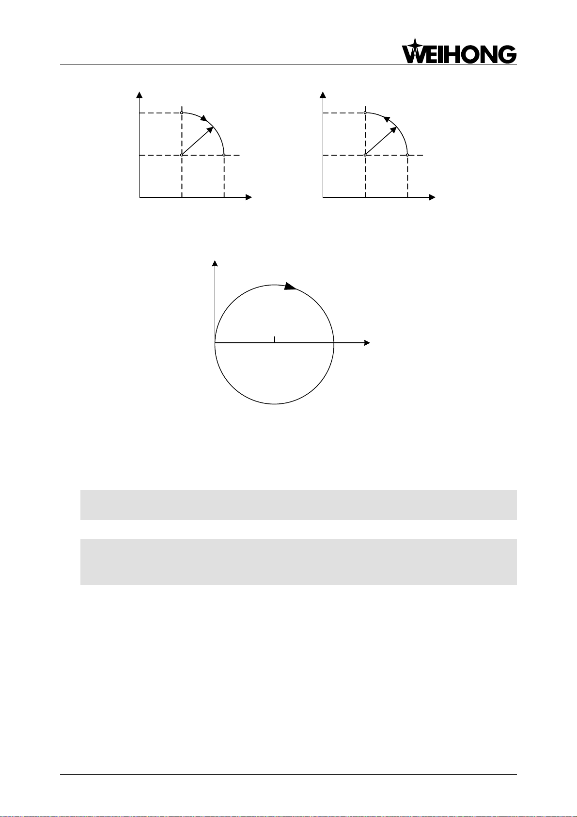
Clockwise and counterclockwise circular interpolation, as shown in Fig. 4-10.
For Fig. 4-10(a)
Solution 1:
G17 G90 X10 Y20
G02 X20 Y10 I0 J-10 F300
Solution 2:
G17 G90 X10 Y20
G02 X20 Y10 R10 F300
For Fig. 4-10 (b)
Solution 1:
G17 G90 X20 Y10
G03 X10 Y20 I-10 J0 F300
Solution 2:
G17 G90 X20 Y10
G03 X10 Y20 R10 F300
20 Specialized, Concentrated, Focused
Page 24
上海维宏电子科技股份有限公司
End point
Start point
X
10
20
10
20
Y
0
R
1
0
(a)
(10,10)
Start point
End point
X
10
20
10
20
Y
0
R
1
0
(b)
(10,10)
20
0
Y
X
40
Weihong Electronic Technology Co., Ltd.
Fig. 4-10 G02/ G03 Programming
Fig. 4-11 A Full Circle Interpolation
Programming Example:
A full circle interpolation, see Fig. 4-11.
Solution 1:
G00 X0 Y0
G02 X0 Y0 I20 J0 F300
Solution 2:
G00 X0 Y0
G02 X20 Y-20 R-20 F300
G02 X0 Y0 R20 F300
Programming Example:
Helical programming in G03, as shown in Fig. 4-12.
Specialized, Concentrated, Focused 21
Page 25

Y
30
Z
End point
Start point
X
30
10
0
Program with G91:
G00 X30 Y0
G91 G17 F300
G03 X-30 Y30 R30 Z10
Program with G90:
G00 X30 Y0
G90 G17 F300
G03 X0 Y30 R30 Z10
Fig. 4-12 Helical Programming
K can also be used to specify the pitch in Fig. 4-12.
G00 X30 Y0
G90 G17 G03 X0 Y30 R30 Z10 K10 F300
上海维宏电子科技股份有限公司
Weihong Electronic Technology Co., Ltd.
G04 Dwell
Command Format: G04 P_
Description:
P_: the dwell time in ms
G04 can be used in the following situations:
1. When cutting a corner, the dwell command can be used to guarantee a sharp corner.
2. In machining a not through hole, when the cutter reaches the appointed depth, G04 can be
used to stop tool feed. After the spindle rotates more than one circle, execute tool retract to get a
smooth hole bottom.
3. After boring a hole, the spindle should be stopped and dwell for 1~3s until totally stopped
before tool retract in order to avoid thread scratches and ensure the smoothness of workpiece.
4. In transverse turning, G04 can be used before tool retract to make sure the spindle rotates at
least one circle.
5. When chamfering or centering on a lathe, the dwell command, spindle on and tool change, etc.
can be used to make sure the smoothness of chamfer surface and conical surface of center hole.
The dwell command comes into effect after the motion of last program block ends (the speed is
0). G04 dwells for the specified time, only effective in the program block containing it.
Inserting G04 between two program blocks can interrupt machining for the specified time, such
as in free cutting, and the time is determined by P function word, in ms.
Programming Example:
G04 P1000 ’dwell for 1000ms
22 Specialized, Concentrated, Focused
Page 26
上海维宏电子科技股份有限公司
Tool Moving Direction
Tool Moving Direction
Tool Rotary Direction
Offset
Left Compensation along
Tool Moving Direction
Tool Rotary Direction
Offset
Right Compensation along
Tool Moving Direction
Weihong Electronic Technology Co., Ltd.
Tool Commands
G40, G41, G42 Cutter Radius Compensation
Command Format:
G41 D_
G42 D_
G40
Description:
G40: cutter radius compensation cancel
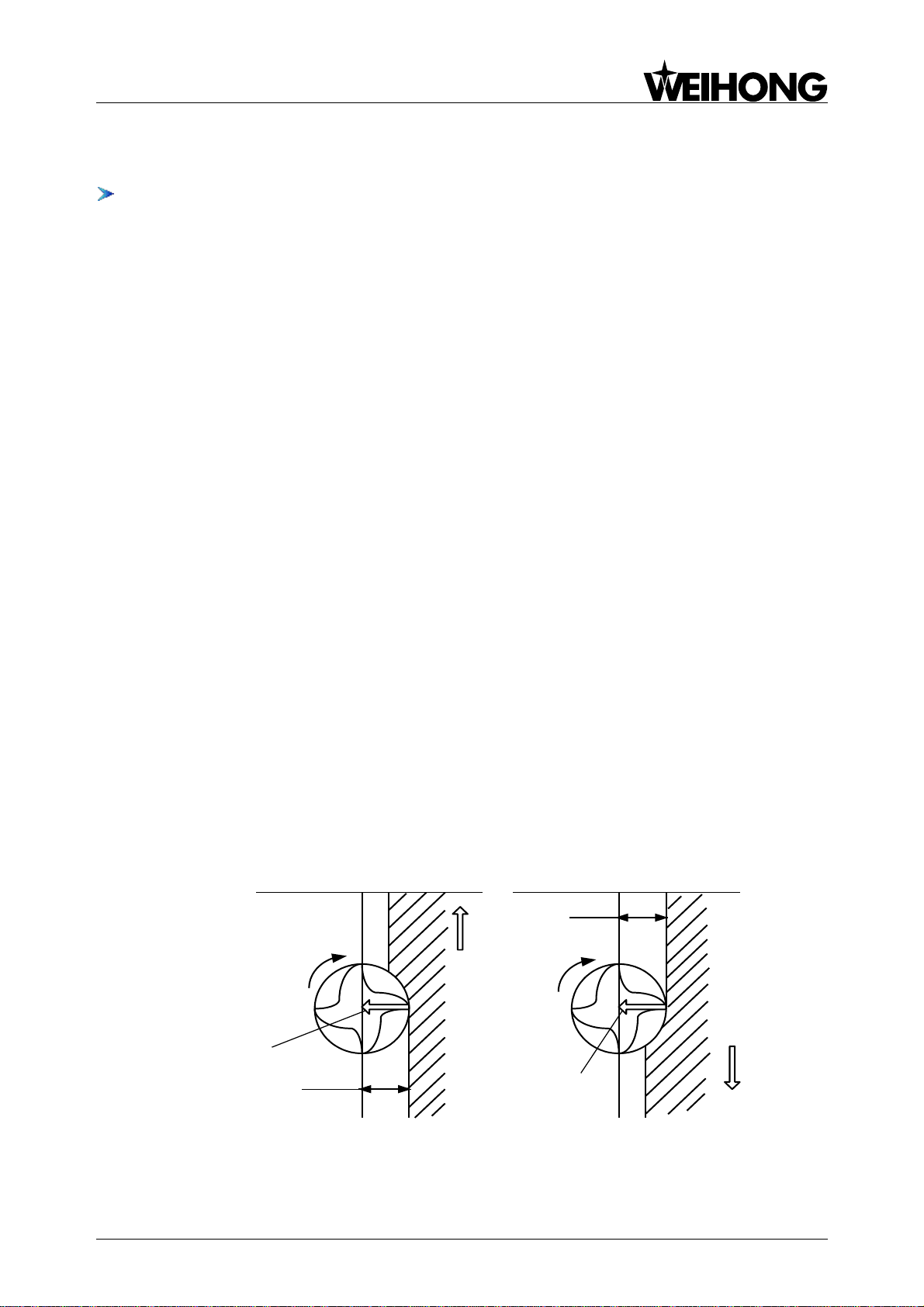
G41: left cutter compensation (the cutter offsets radius distance on the left side of cutter moving
direction)
G42: right cutter compensation (the cutter offsets radius distance on the right side of cutter
moving direction)
D_: parameter of G41/G42, i.e. tool compensation no. (D00~D07), denotes the radius
compensation value corresponding to the tool compensation list
The switch among cutter radius compensation planes must be executed when compensation is
off.
The establishment and cancel of cutter radius compensation can only use G00 or G01 command
instead of G02 or G03.
When using cutter radius compensation, the radius value must be measured accurately and then
saved into the memory as the cutter path offset (cutter radius value). D code is used in programming
to make cutter offset no. correspond to cutter radius value.
When G41 (G42) is used, the cutter will move a radius distance to the offset position. After the
execution of G41 (G42), the tool is immediately located to the perpendicular position of start position
of program block, and the value of movement depends on the offset.
Specialized, Concentrated, Focused 23
(a) Left Compensation (b) Right Compensation
Fig. 4-13Cutter Compensation Direction
Page 27
上海维宏电子科技股份有限公司
X,Y(10,10)
Cutter, G40
G42
G41
Center
10
0 10 20
Current moving
direction
Previous moving
direction
Weihong Electronic Technology Co., Ltd.
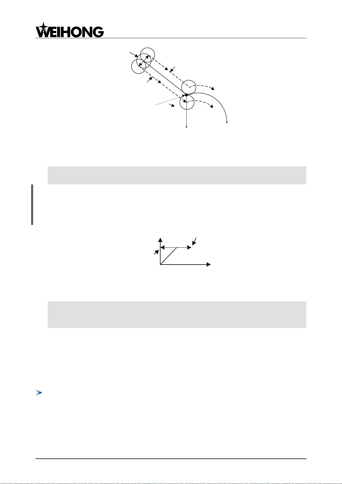
Fig. 4-14 Cutter Radius Compensation
Programming Example:
See Fig. 4-14 Cutter Radius Compensation.
G17 G01 G41 (G42) X_ Y_ F_ D_ ’executes linear interpolation and cutter radius compensation
G02 X_ Y_ I_ J_ ’circular interpolation
Note:
In the process of compensation or when compensation off, current moving direction of cutter cannot
be opposite to last direction.
Fig. 4-15 Schematic Diagram of Cutter Moving Direction
For example:
G92 G0 X0 Y0
G0 G41 X10 Y10 D01 F1000
G1 X20 Y10
If G1 X5 Y10 is added here, an error will appear, because the direction is opposite to that of
above-mentioned instruction. Change it to G1 X10 Y50, or other instruction not opposite to the last
direction.
G0 G40 X0 Y10 ’this instruction is also wrong, because the moving direction of cutter is
opposite to the last direction. It will be right if it is changed to G0 G40 X0 Y0.
G43, G44, G49 Tool Length Compensation
Command Format:
G43 H_
G44 H_
G49
24 Specialized, Concentrated, Focused
Page 28
上海维宏电子科技股份有限公司
Z
X
3
10
Tool nose position after
length compensation
Tool nose position before
length compensation
0
Weihong Electronic Technology Co., Ltd.
Description:
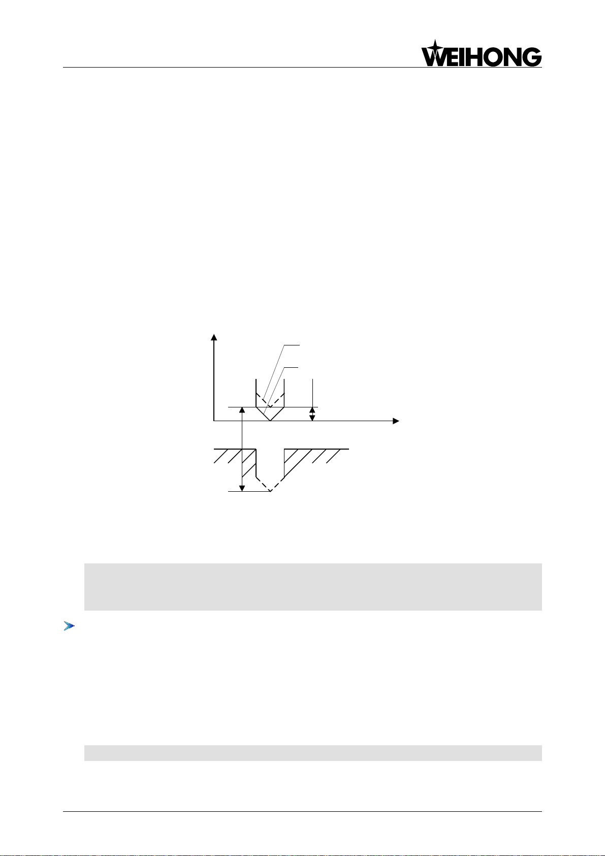
G49: tool length compensation off
G43: compensation along positive direction (end point value of compensation axis adds offset
value)
G44: compensation along negative direction (end point value of compensation axis subtracts
offset value)
H_: parameter of G43/G44, i.e. tool length compensation offset no. (H00~H07), denotes length
compensation value relative to the tool compensation list.
Tool length compensation is used to compensate the deviation of tool length, which subtracts or
adds the saved tool offset value from or to the command value of Z-axis.
G43 and G44 are modal commands. When G43 or G44 is programmed, they will be always
effective until G49 command appears to cancel them.
Fig. 4-16 Tool Length Compensation
Programming Example:
See Fig. 4-16 for tool length compensation.
G90 G00 X5 Z0 F300
G43 G0 Z10 H1 ’length compensation to the cutter
G01 Z-10 F1000
G923 Directly Set Tool Offset
Command Format: G923 X_Y_Z_ P_
Description:
Sets tool offset value for the specified tool; axes not listed out will not be modified.
P_: to specify cutter no.
For example:
G923 Z 2.392 P1
It indicates the tool offset value of cutter no.1 is 2.392.
Specialized, Concentrated, Focused 25
Page 29
上海维宏电子科技股份有限公司
G Code
Drilling
operation
Operation at bottom of
hole
Retraction
operation
Application
G73
Intermittent
feed
----
Rapid motion
High speed peck drilling
cycle
G74
Cutting feed
Dwell, then spindle CW
Cutting feed
Left tapping cycle
*G76
Cutting feed
Oriented spindle stop with
one displacement
Rapid motion
Fine boring cycle
G80
----
----
----
Cycle off
G81
Cutting feed
----
Rapid motion
Drilling cycle
G82
Cutting feed
Dwell
Rapid motion
Drilling cycle of dwell at
bottom of hole
G83
Intermittent
feed
----
Rapid motion
Peck drilling cycle
G84
Cutting feed
Dwell, then spindle CCW
Cutting feed
Taping cycle
G85
Cutting feed
----
Cutting feed
Drilling cycle
G86
Cutting feed
Spindle stop
Rapid motion
Drilling cycle
*G87
Cutting feed
Spindle CW
Rapid motion
Fine back boring cycle
*G88
Cutting feed
Dwell, then spindle stop
Manual
displacement
Semi-automatic fine
boring cycle
Weihong Electronic Technology Co., Ltd.
If P is omitted, it indicates setting tool offset value for the current tool.
Programming Example (the cutter lifting program in Public.dat)
M802 P196609
M801 MSG"|D| wait for tool calibration signal"
G904 FZ-60 PZ=#CALIBRATION_SW LZ1
M801 MSG""
M802 P196608
G903 G00 G91 Z5
G923 z0
G906
G923 Z = #CURWORKPOS.Z-#MOBICALI_THICKNESS–5
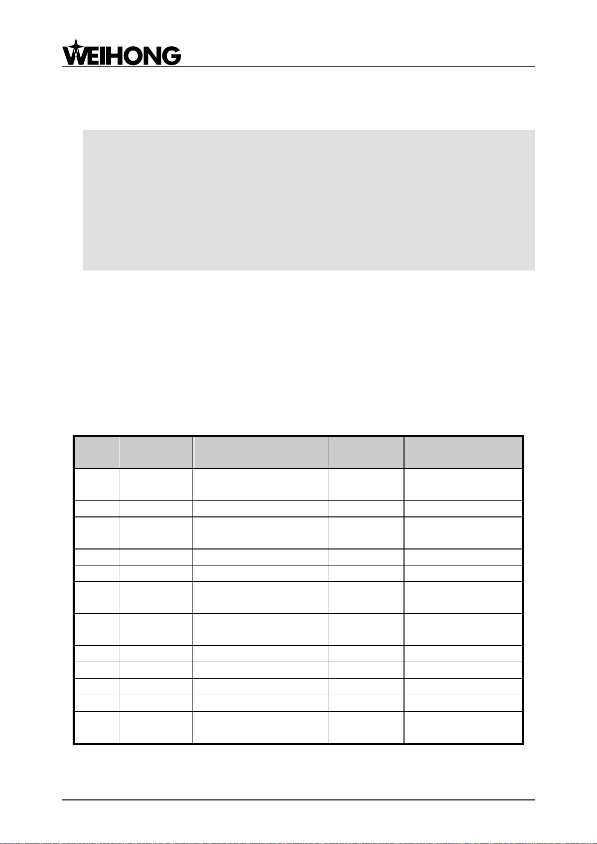
Canned Cycle Function
The canned cycles of CNC mills are mainly used for machining holes, including drilling, boring
and tapping. With one program block, you can accomplish one or a full set of hole machining
operation. When continuing hole machining, if there is no need to change hole machining operations,
all the modal data in the program needn’t to be written, which can greatly simplify the program.
Description of each command is shown in the following table.
26 Specialized, Concentrated, Focused
Page 30
上海维宏电子科技股份有限公司
G Code
Drilling
operation
Operation at bottom of
hole
Retraction
operation
Application
G89
Cutting feed
Dwell
Cutting feed
Boring cycle of dwell at
bottom of hole
Operation 1
Initial Point
Operation 2 Operation 6
Operation 5
Operation 3
Operation 4
Feed
Point R
Rapid Traverse
Weihong Electronic Technology Co., Ltd.
Notes: G76, G87, and G88 commands are not supported for the time being.
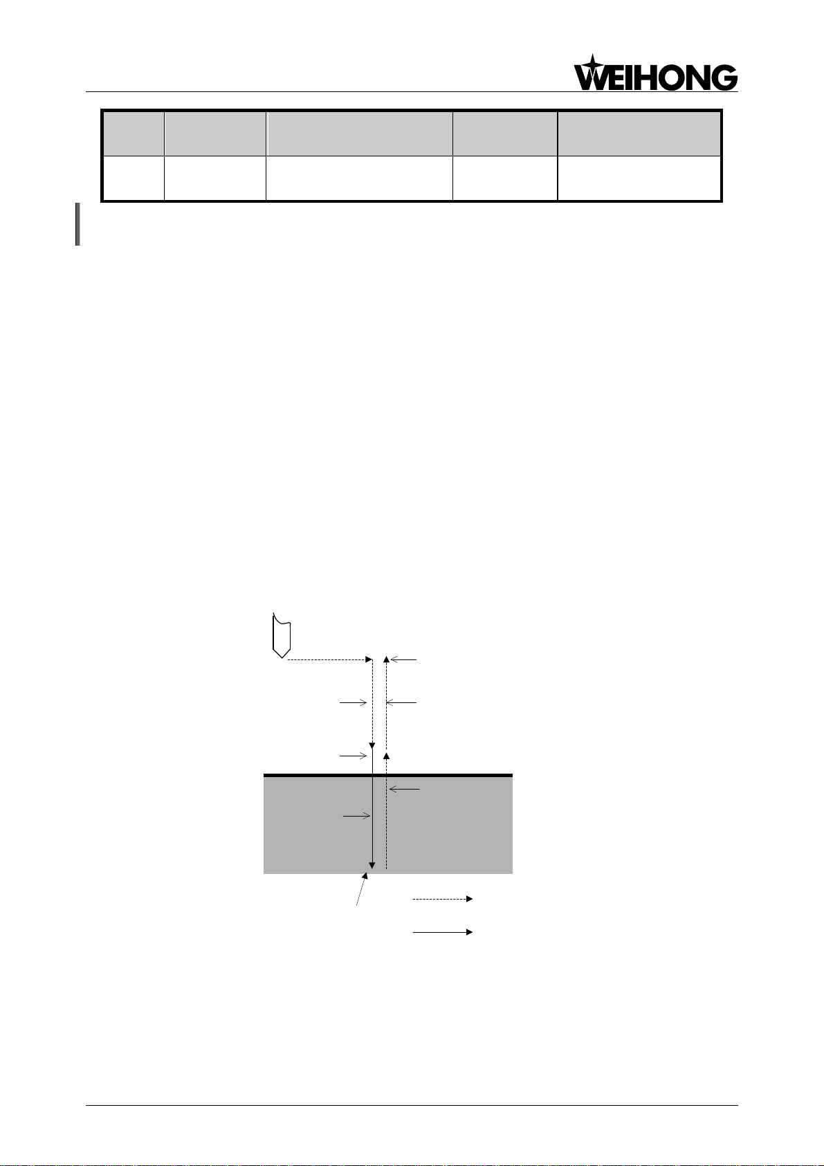
Canned Cycle Operations
Generally speaking, canned cycle of hole machining is comprised of the following six operations,
see Fig. 4-17.
Operation 1: positioning of X axis and Y axis---the cutter is rapidly located to the position of hole
machining.
Operation 2: rapid traverse to point R---the cutter rapidly feeds from initial point to point R.
Operation 3: hole machining----executing hole machining at the mode of cutting feed.
Operation 4: operations at bottom of hole----including dwell, exact stop of spindle, cutter
displacement, and so on.
Operation 5: return to point R----for continuing hole machining and safely moving the cutter.
Operation 6: return to initial point at rapid traverse rate----generally, initial point is selected after
hole machining completed.
Initial Plane
Initial plane is a plane specified for a safe plunge. The distance between initial plane and
workpiece surface can be set within the safe limit.
Specialized, Concentrated, Focused 27
Fig. 4-17 Operation Sequence of Canned Cycle
Page 31
上海维宏电子科技股份有限公司
Point R
R
Z
Point Z
Z=0
Point R
R
Point Z
Z
G90 (Absolute Coordinate)
G91 (Increment Coordinate)
Weihong Electronic Technology Co., Ltd.
Point R Plane
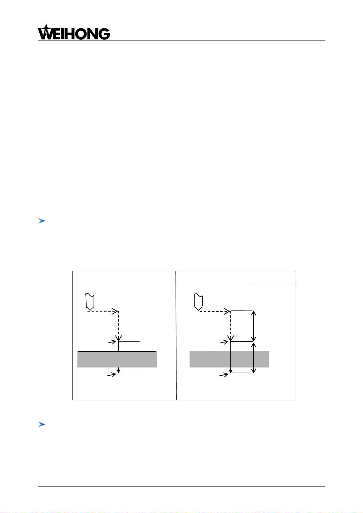
Point R plane is also named R REFER plane; it is a plane where the cutter moves at a speed
from rapid traverse rate (G00) to cutting workpiece speed (GXX). The distance between workpiece
surface and point R, generally within 2~5mm, mainly varies with the dimension of workpiece surface.
Hole Bottom Plane
When machining a blind hole, hole bottom plane is Z-axis height at the bottom of hole. When
machining a through hole, the cutter usually goes beyond the hole bottom a certain distance to make
sure all holes are machined to the specified depth. When drilling a hole, the impact of drill on hole
depth should also be taken into consideration.
Hole machining cycle is not related to plane selection command (G17, G18, and G19).
Whichever plane is selected, hole machining is positioning in XY plane and drilling in Z-axis.
Canned Cycle Codes
Data Form
Data of Address R and Address Z in canned cycle commands are specified in incremental mode
(G91); R indicates the distance from initial point to point R, and Z indicates the distance from point R
to point Z in the hole bottom plane (refer to Fig. 4-18).
Gxx Hole Machining Mode
The command format of hole machining is as shown below:
Gxx X_Y_Z_R_Q_P_F_K_;
X_Y_: position of the hole to be machined (absolute/incremental coordinate)
28 Specialized, Concentrated, Focused
Fig. 4-18 Canned Cycle
Page 32

上海维宏电子科技股份有限公司
Weihong Electronic Technology Co., Ltd.
Z_: the position of point Z in the hole bottom plane (absolute programming); the distance from
point R to point Z in the hole bottom plane (incremental programming)
R_: the position of point R (absolute programming); the distance from the initial point to point R
(incremental programming)
Q_: the cutting depth each time (incremental and positive)
P_: the dwell time at bottom of hole, in ms, with no decimal point
F_: feed speed; even if the canned cycle is cancelled, this modal data is still effective in the
subsequent machining.
K_: number of repeats, with default as K1. K (a non-modal command) is only effective in the
block containing it. Under G91 mode, with setting this parameter, one block can implement the
machining of several isometric holes distributed in one straight line. Under G90 mode, this parameter
can specify the repeated machining times on the same position.
Command of hole machining mode, and Z, R, Q, and P, are all modal. They will remain in effect
until hole machining mode is cancelled. Therefore, these commands can be specified at the
beginning of the program, and then it is unnecessary to specify them again in the following
consecutive machining; if the data of a certain hole is changed (such as: hole depth), you only need to
modify this data.
G80 command is used to cancel hole machining mode; if any G code of Group 01
(G00/G01/G02/G03…) appears in the program block, the hole machining mode will also be
automatically cancelled. In other words, as for canceling a canned cycle, G80 and G code of Group
01 function the same.
Canned Cycle Commands
Followings are the detailed description of various hole-machining modes.
G73 High Speed Chipbreaking Drilling Cycle
Command Format: G73 X_Y_Z_R_Q_ F_ K_;
Description:
X_Y_: hole position data (absolute/incremental coordinate)
Z_: the position of point Z in the hole bottom plane (absolute programming); the distance from
point R to point Z at the bottom of hole (incremental programming)
R_: the position of point R (absolute programming); the distance from the initial point to point R
(incremental programming)
Q_: the cutting depth each time (incremental and positive, minus sign will be ignored)
F_: feed rate, even if the canned cycle is cancelled, this modal data is still effective in the
subsequent machining.
Specialized, Concentrated, Focused 29
Page 33
上海维宏电子科技股份有限公司
Point R
Q
Q
Q
Point Z
P
δ: Parameter setting
δ
δ
G98
(X,Y)
Initial Point
Point R
Q
Q
Q
Point Z
P
δ: Parameter setting
δ
δ
G99
(X,Y)
Initial Point
Weihong Electronic Technology Co., Ltd.
K_: number of repeats
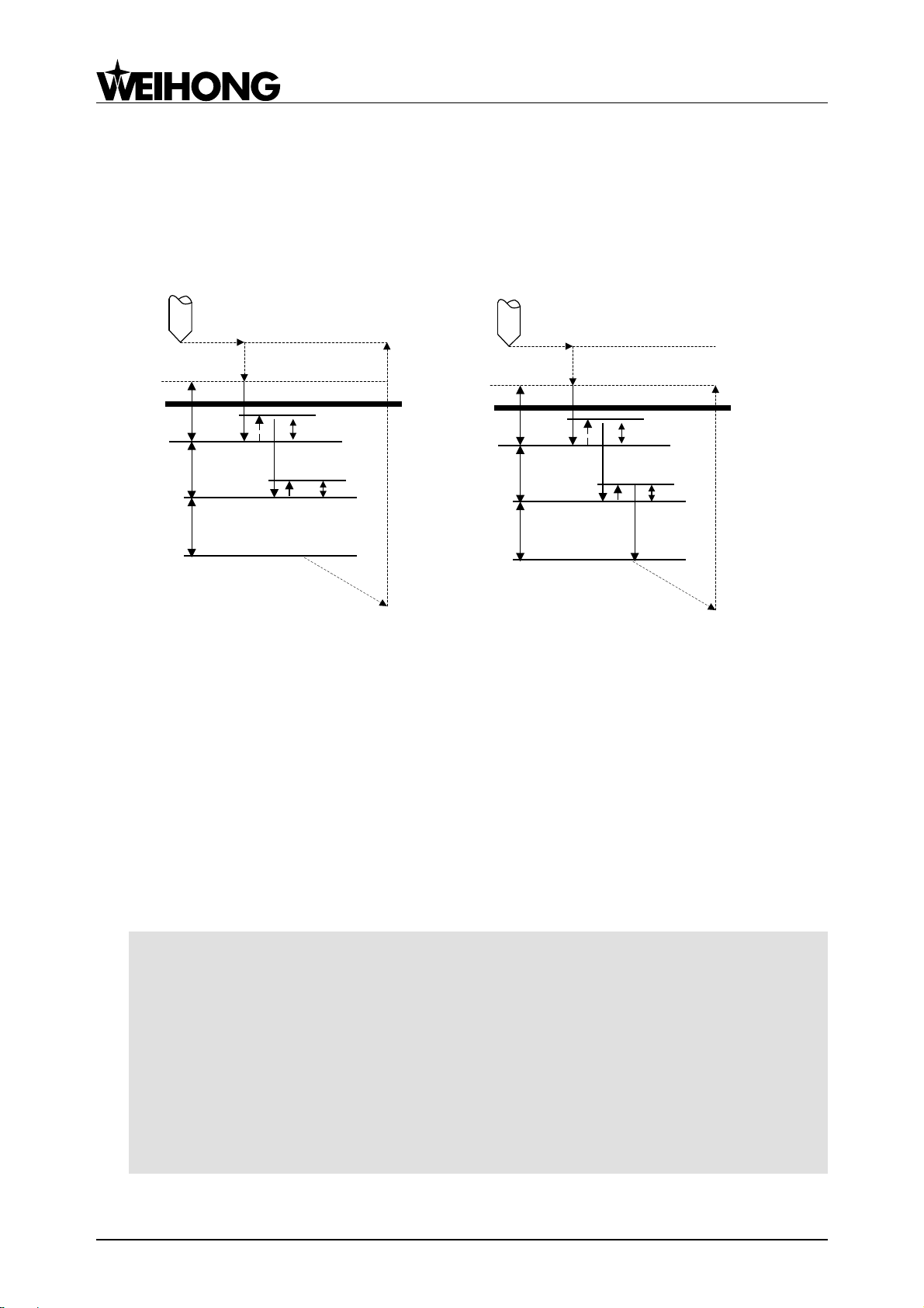
Hole-machining process is as shown in Fig. 4-19. It is easy to break and remove chips by
intermittent feeding in Z-axis. Q specifies each time cutting depth, and ―‖ is set by the parameter
(G73_G83 retract amount).
Fig. 4-19 G73 Machining Process
Process Description:
1. The cutter rapidly moves to the specified hole position (X, Y);
2. Moves to the appointed point R;
3. Moves down Q relative to the present drilling depth;
4. Rapidly moves upward retract distance (set by the parameter ―retract amount‖);
5. Repeats the above drilling operations until reaching point Z at the bottom of hole;
6. Returns to the initial point (G98) or R point (G99) at G00 speed;
Programming Example:
F1200. S600
M03 ’spindle CW on
G90
G00 X0. Y0. Z10. ’moving to the initial point.
G17
G90 G99
’Setting coordinates of point R, point Z and hole 1, with cutting depth each time as 2.0, and
drilling speed as 800
G73 X5. Y5. Z-10. R-5. Q2. F800
X25. ’hole 2
30 Specialized, Concentrated, Focused
Page 34
上海维宏电子科技股份有限公司
Z
Spindle CW after P
R
Initial Point
G98
G99
Z
Spindle CCW after P
Initial Point
Spindle CCW after P
Spindle CW after P
R
(X,Y)
(X,Y)
Weihong Electronic Technology Co., Ltd.
Y25. ’hole 3
G98 X5. ’hole 4, and setting to return to the initial point
X10. Y10. Z-20. ’hole 5, and setting a new point Z as -20
G80
M05 ’drill stop
M02
G74 Left Tapping Cycle
Command Format: G74 X_Y_Z_R_P_F_K_;
Description:
X_Y_: hole position data (absolute/incremental coordinate)
Z_: the position of point Z at the bottom of hole (absolute programming); the distance from point
R to point Z at the bottom of hole (incremental programming)
R_: the position of point R (absolute programming); the distance from the initial point to point R
(incremental programming)
P_: the dwell time at the bottom of hole, in ms, with no decimal point
F_: feed speed, even if the canned cycle is cancelled, this modal data is still effective in the
subsequent machining. (Currently, tapping speed is specified by the parameter ―spindle speed when
tapping‖, instead of by this F data.)
K_: number of repeats (repeated movement and drilling, effective under G91 incremental mode)
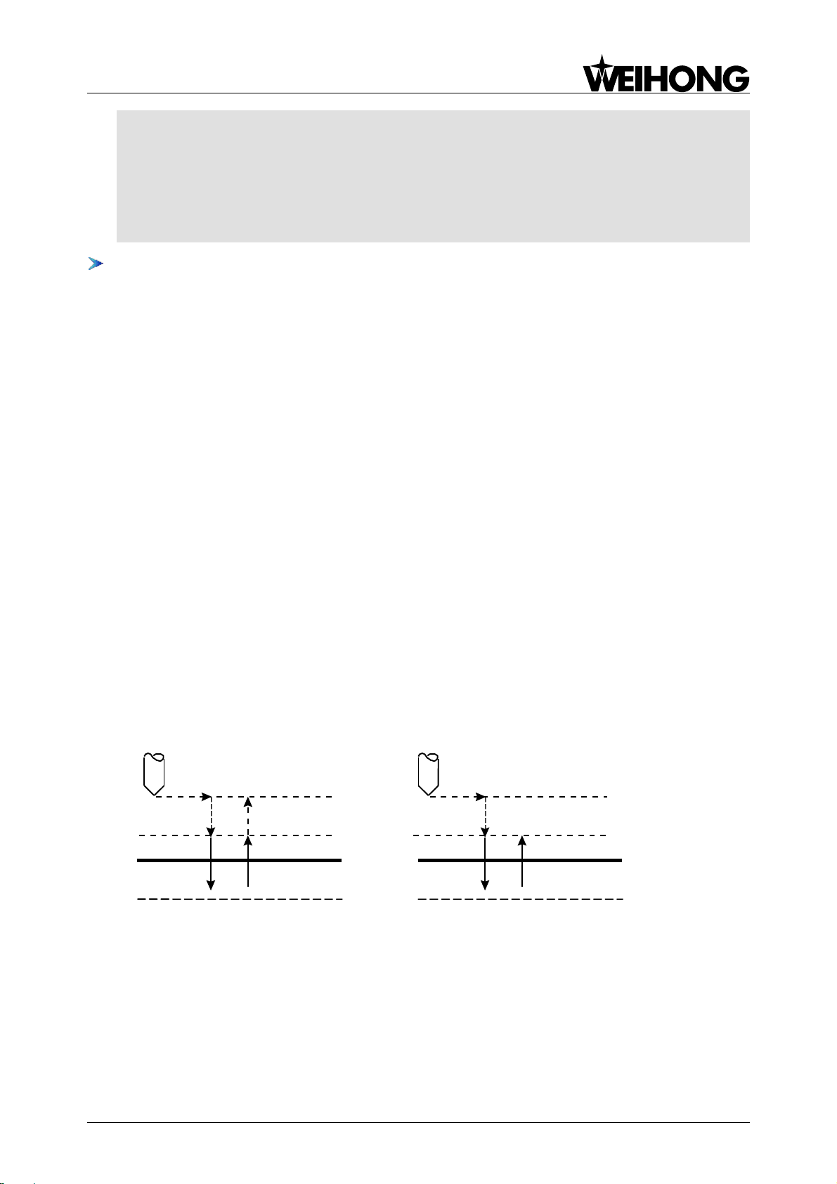
Hole-machining process is as shown in Fig. 4-20. In G98, the cutter will return to the initial point
after hole-machining is finished. But in G99, the cutter will return to point R after hole-machining is
finished.
Specialized, Concentrated, Focused 31
Fig. 4-20 G74 Machining Process
Process Description:
1. The cutter moves to the specified hole position (X, Y) at G00 speed;
2. Goes down to the specified point R at G00 speed;
Page 35

上海维宏电子科技股份有限公司
Weihong Electronic Technology Co., Ltd.
3. Taps down to point Z at the bottom of the hole in G01;
4. Drill CW after P;
5. Retracts to point R in G01;
6. Drill CCW after P;
7. Retracts to the initial point (G98) or point R (G99) in G00.
Programming Example:
F1200. S600
G90
G00 X0. Y0. Z10. ’moving to the initial point.
G17
M04 ’drill CCW on
G90 G99
’Setting the coordinates of point R, point Z and hole 1, with dwell as 2s and drilling speed as 800
G74 X5. Y5. Z-10. R-5. P2000. F800
X25. ’hole 2
Y25. ’hole 3
G98 X5. ’hole 4, and setting to return to the initial point.
X10. Y10. Z-20. ’hole 5, and setting a new point Z as -20
G80
M05 ’drill stop
M02
G76 Fine Boring Cycle
This command is not supported at the moment.
Command Format: G76 X_Y_Z_R_Q_P_F_K_;
Description:
X_Y_: hole position data (absolute/incremental coordinate)
Z_: the position of point Z at the bottom of the hole (absolute programming); the distance from
point R to point Z at the bottom of the hole (incremental programming)
R_: the position of point R (absolute programming); the distance from the initial point to point R
(incremental programming)
Q_: displacement of the tool at the bottom of the hole (incremental and positive, and minus sign
will be ignored)
P_: the dwell time of tool at the bottom of the hole, in ms, with no decimal point
F_: feed speed, even if the canned cycle is cancelled, this modal data is still effective in the
subsequent machining.
K_: number of repeats (repeated movement and drilling, effective under G91 incremental mode)
32 Specialized, Concentrated, Focused
Page 36
上海维宏电子科技股份有限公司
Z
R
Initial Point
G98
Z
R
Initial Point
G99
P
P
OSS
OSS
δ
δ
Spindle CCW
Spindle CCW
(X,Y)
(X,Y)
Tool
Offset
δ
OSS
(Oriented Spindle Stop)
Oriented Spindle Stop (OSS)
G17
G18
G19
0
+X
+Z
+Y 1 -X
-Z
-Y 2 +Y
+X
+Z 3 -Y
-X
-Z
Weihong Electronic Technology Co., Ltd.
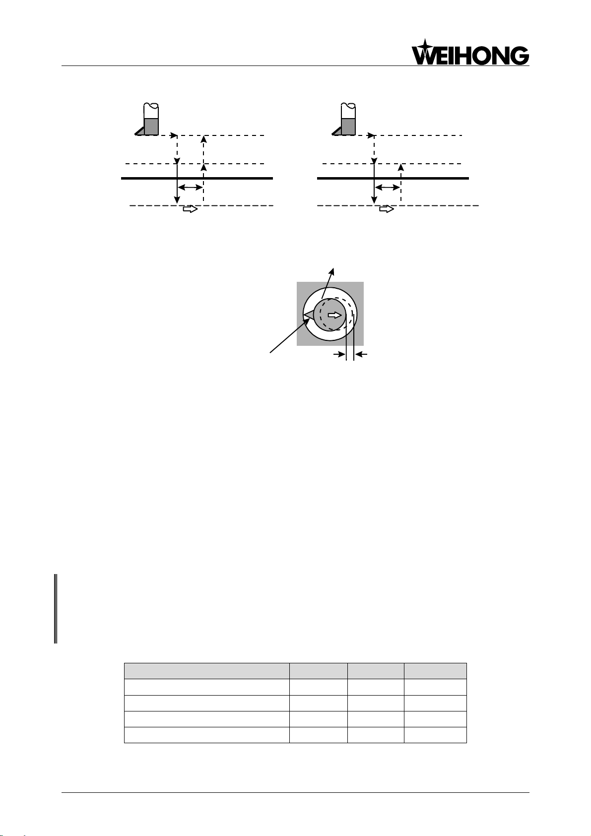
Fig. 4-21 G76 Machining Process
Fig. 4-22 Oriented Spindle Stop (OSS) Demonstration
Process Description:
1. The cutter moves to the specified hole position (X, Y) in G00;
2. Moves down to the specified point R in G00 (without spindle orientation);
3. Moves down to the point Z at the bottom of the hole in G01, after P, oriented spindle stop
executed;
4. Shifts δ distance (the offset distance);
5. Retracts to the initial point (G98) or point R (G99) in G00;
6. Spindle CCW on.
※ Alarm:
As a Modal Value requested in G76 cycle, the value of Q must be specified carefully, because it is
also used in G73/G83.
OSS (Oriented Spindle Stop) direction is decided by the parameter ―Oriented Spindle Stop‖:
Specialized, Concentrated, Focused 33
Page 37
上海维宏电子科技股份有限公司
Z
R
Initial Point
G98
Z
R
Initial Point
G99
(X,Y)
(X,Y)
Weihong Electronic Technology Co., Ltd.
Programming Example:
F1200 S600
M03 ’spindle CW on
G90
G00 X0 Y0 Z10 ’moving to the initial point
G17
G90 G99
’Specifying the coordinates of point R, point Z and hole 1, with the displacement at the bottom of
hole as 2.0, dwell time as 5s, and machining speed as 800
G76 X5. Y5. Z-10. R-5. Q2. P5000. F800
X25. ’hole 2
Y25. ’hole 3
G98 X5. ’hole 4, and setting to return to initial point
X10. Y10. Z-20. ’hole 5, and specifying the new point Z as -20.0
G80
M05 ’drill stop
M02
G81 Drilling Cycle
Command Format: G81 X_Y_Z_R_F_ K_;
Description:
X_Y_: hole position data (absolute/incremental coordinate)
Z_: the position of point Z at the bottom of the hole (absolute programming); the distance from
point R to point Z at the bottom of the hole (incremental programming)
R_: the position of point R (absolute programming); the distance from the initial point to point R
(incremental programming)
F_: feed speed, even if the canned cycle is cancelled, this modal data is still effective in the
subsequent machining.
K_: number of repeats (repeated movement and drilling, effective under G91 increment mode)
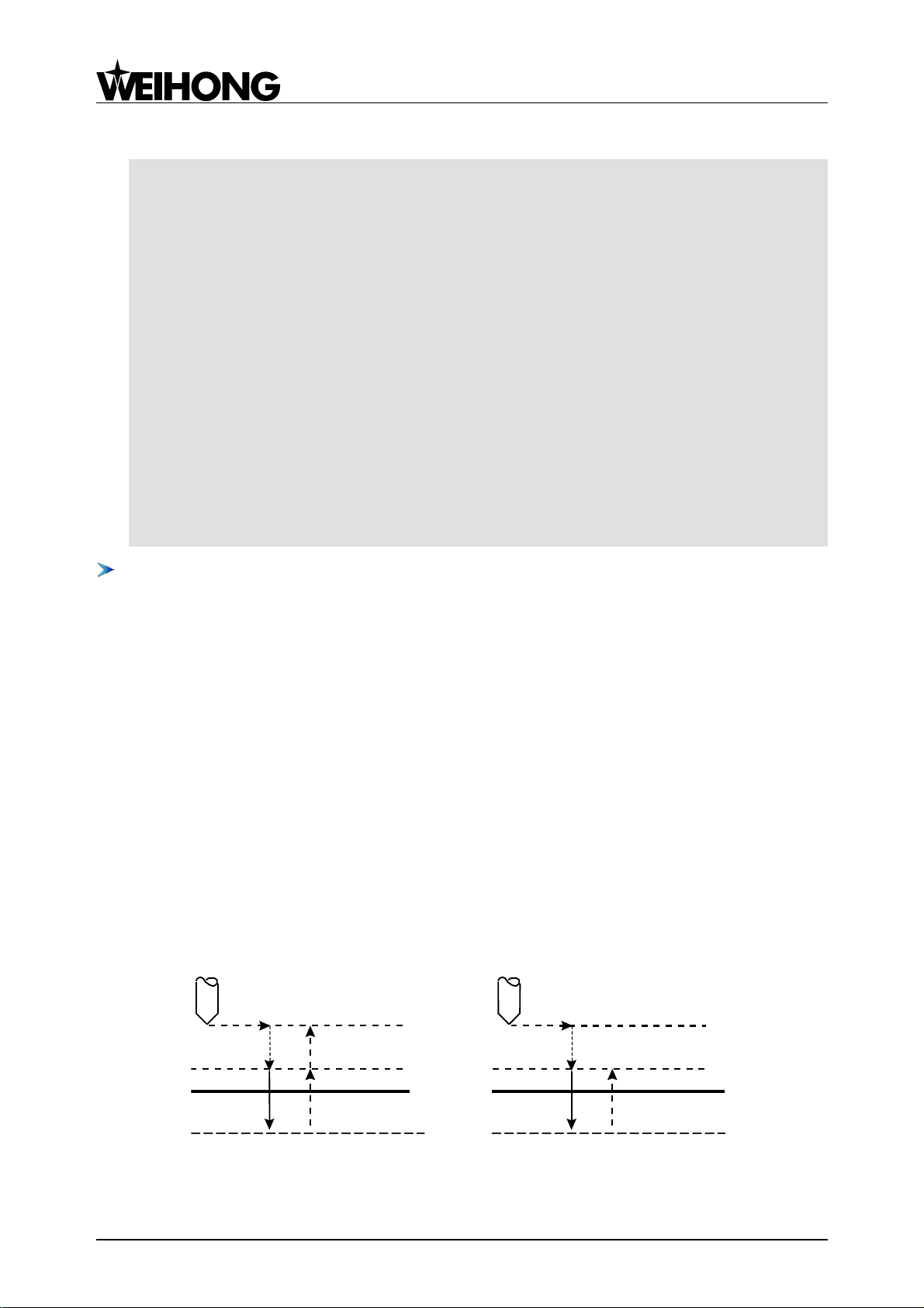
Hole machining operation is as shown in Fig. 4-23. G81 is used for general drilling.
Fig. 4-23 G81 Machining Process
34 Specialized, Concentrated, Focused
Page 38

上海维宏电子科技股份有限公司
Weihong Electronic Technology Co., Ltd.
Description of Machining Process:
1. The cutter moves to the specified hole position (X, Y) in G00;
2. Moves down to the specified point R in G00;
3. Moves down to point Z at the bottom of the hole in G01;
4. Retracts to the initial point (G98) or point R (G99) in G00.
Programming Example:
F1200. S600
G90
G00 X0. Y0. Z10. ’moving to the initial point
G17
G90 G99
’Setting the coordinates of point R, point Z and hole 1, with machining speed as 800
G81 X5. Y5. Z-10. R-5. F800
X25. ’hole 2
Y25. ’hole 3
G98 X5. ’hole 4, and return to initial point
X10. Y10. Z-20. ’hole 5, and setting the new point Z as -20
G80
M02
G82 Drilling Cycle of Dwell at the Bottom of Hole
Command Format: G82 X_Y_Z_R_P_F_K_;
Description:
X_Y_: hole position data (absolute/incremental coordinate)
Z_: the position of point Z at the bottom of the hole (absolute programming); the distance from
point R to point Z at the bottom of the hole (incremental programming)
R_: the position of point R (absolute programming); the distance from the initial point to point R
(incremental programming)
P_: the dwell time of the cutter at the bottom of the hole, in ms, with no decimal point
F_: feed speed, even if the canned cycle is cancelled, this modal data is still effective in the
subsequent machining.
K_: number of repeats (repeated movement and drilling, effective under G91 incremental mode)
Specialized, Concentrated, Focused 35
Page 39

Weihong Electronic Technology Co., Ltd.
Z
R
Initial Point
P
G98
Z
R
Initial Point
P
G99
(X,Y)
(X,Y)
Fig. 4-24 G82 Machining Process
Process Description:
1. The cutter moves to the specified hole position (X, Y) in G00;
2. Moves down to the specified point R in G00;
3. Moves down to point Z at the bottom of the hole in G01;
上海维宏电子科技股份有限公司
4. Pauses for P;
5. Retracts to the initial point (G98) or point R (G99) in G00.
Programming Example:
F1200. S600
G90
G00 X0. Y0. Z10. ’moving to the initial point
G17
M03 ’spindle CW on
G90 G99
’Setting the coordinates of point R, point Z and hole 1, with dwell time as 2s, drilling speed as 800
G82 X5. Y5. Z-10. R-5. P2000. F800
X25. ’hole 2
Y25. ’hole 3
G98 X5. ’hole 4, and setting to return to the initial point
G80
M05 ’spindle stop
M02
G83 Deep Hole Peck Drilling Cycle
Command Format: G83 X_Y_Z_R_Q_F_K_;
Description:
X_Y_: hole position data (absolute/incremental coordinate)
Z_: the position of point Z at the bottom of the hole (absolute programming); the distance from
point R to point Z at the bottom of the hole (incremental programming)
R_: the position of point R (absolute programming); the distance from the initial point to point R
36 Specialized, Concentrated, Focused
Page 40
上海维宏电子科技股份有限公司
Q
Q
Q
δ
δ
Point Z
Point R
Initial point
P
G98
Q
Q
Q
δ
δ
Point Z
Point R
Initial point
P
G99
(X, Y)
(X, Y)
δ: Set by parameter
δ: Set by parameter
Weihong Electronic Technology Co., Ltd.
(incremental programming)
Q_: the peck depth each time(positive and incremental, minus mark will be ignored)
F_: feed speed, even if the canned cycle is cancelled, this modal data is still effective in the
subsequent machining.
K_: number of repeats (repeated movement and drilling, effective under G91 incremental mode)
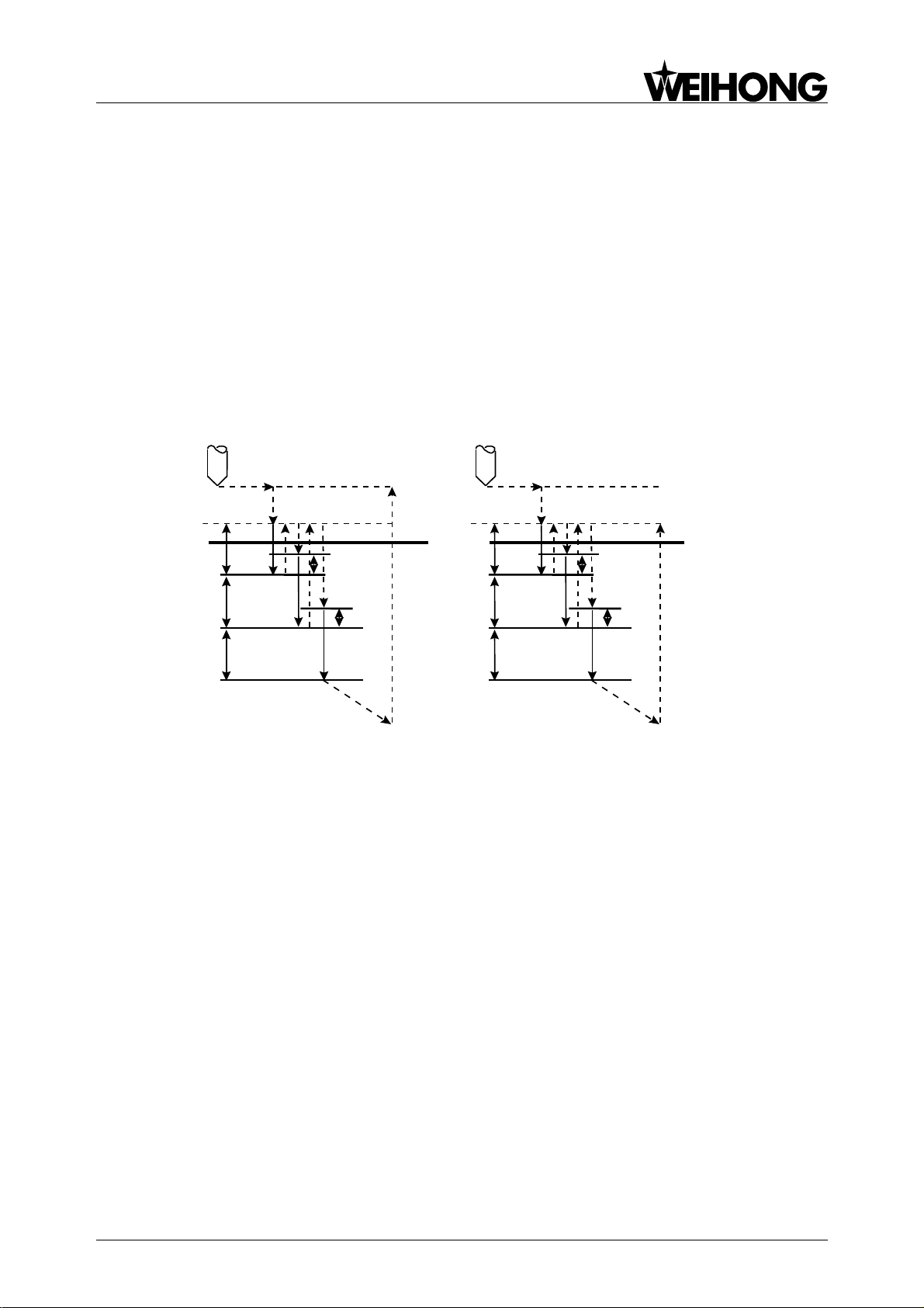
The machining process of hole is as shown in Fig. 4-25. Slightly different from G73, the tool will
retract to plane R after each intermittent feed in G83. The ―‖ here, set by the parameter ―G73_G83
retract amount‖, refers to the distance between the feed plane where the cutter changes from G00 to
Gxx and the previous peck depth. G83 is especially for machining deep holes.
Fig. 4-25 G83 Machining Process
Process Description:
1. The cutter moves to the specified hole position (X, Y) in G00;
2. Moves to the specified point R in G00;
3. Drills down Q distance with respect to current depth in G01;
4. Retracts to the R plane in G00;
5. Moves down until distance (decided by the parameter ―Retract Amount‖) away from current
drill depth in G00;
6. Drill downs Q distance with respect to current drill depth;
7. Retracts to the R plane in G00;
8. Repeats above drilling operations until reaching point Z at the bottom of the hole;
9. Retracts to the initial point (G98) or point R (G99) in G00.
Specialized, Concentrated, Focused 37
Page 41
上海维宏电子科技股份有限公司
Z
R
Initial Point
Spindle CCW after P
G98
Z
R
Initial Point
Spindle CCW after P
G99
Spindle CW after P
Spindle CW after P
(X,Y)
(X,Y)
Weihong Electronic Technology Co., Ltd.
Programming Example:
F1200. S600
M03 ’spindle CW on
G90
G00 X0. Y0. Z10. ’moving to the initial point
G17
G90 G99
’Specifying the coordinates of point R, point Z and hole 1, with peck depth as 3.0, cutting speed
as 800
G83 X5. Y5. Z-10. R-5. Q3. F800
X25. ’hole 2
Y25. ’hole 3
G98 X5. ’hole 4, and setting to return to the initial point
G80
M05 ’drill stop
M02
G84 Tapping Cycle
Command Format: G84 X_Y_Z_R_P_F_K_;
Description:
X_Y_: hole position data (absolute/incremental coordinate)
Z_: the position of point Z at the bottom of the hole (absolute programming); the distance from
point R to point Z at the bottom of the hole (incremental programming)
R_: the position of point R (absolute programming); the distance from the initial point to point R
(incremental programming)
P_: the dwell time at the bottom of the hole, in ms, with no decimal point
F_: feed speed, even if the canned cycle is cancelled, this modal data still effective in the
subsequent machining. (Currently, tapping speed is set by the parameter ―Spindle Speed When
Tapping‖, instead of by this F data.)
K_: number of repeats (repeated movement and drilling, effective under G91 incremental mode)
38 Specialized, Concentrated, Focused
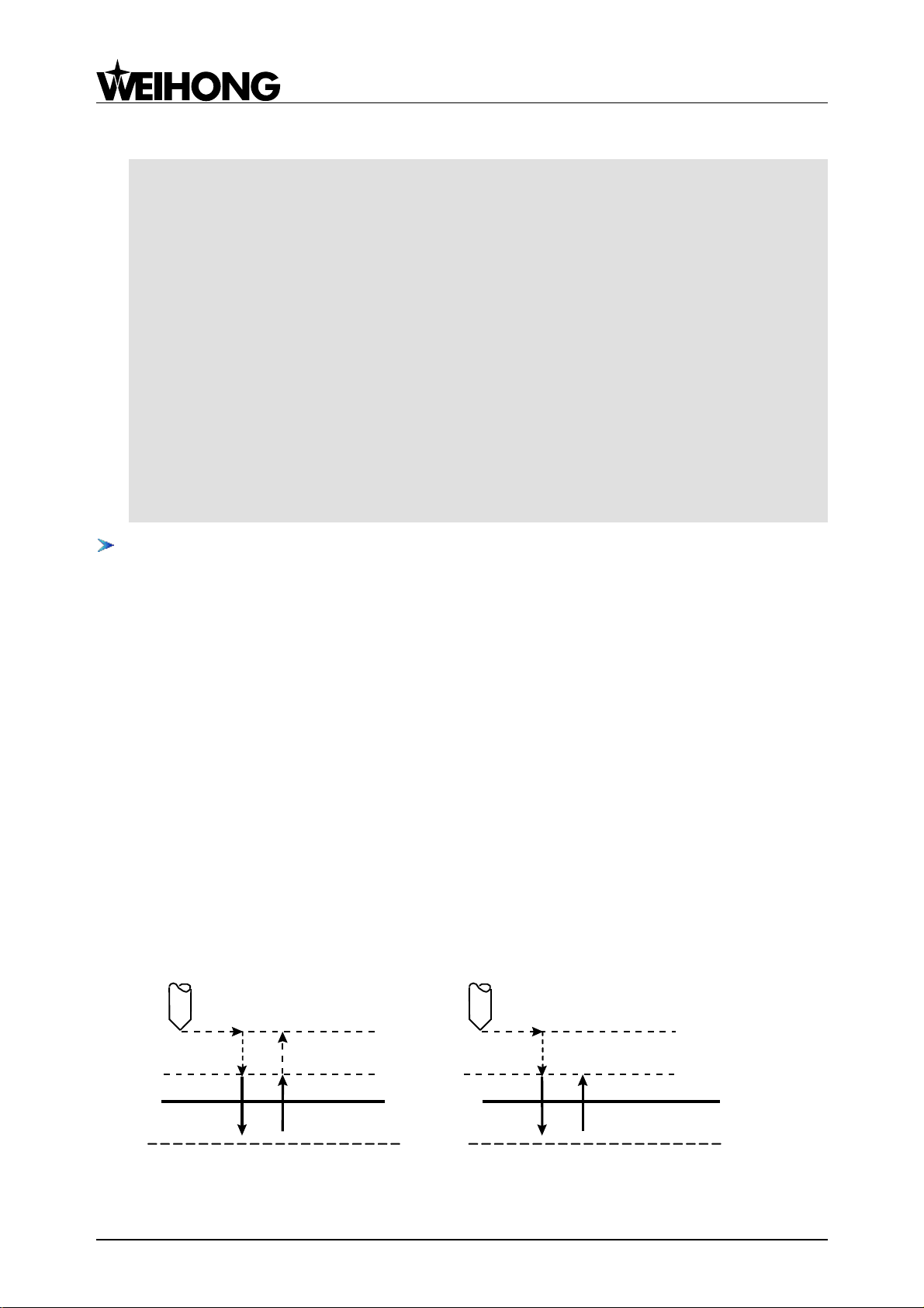
Fig. 4-26 G84 Machining Process
Page 42

上海维宏电子科技股份有限公司
Weihong Electronic Technology Co., Ltd.
Process Description:
1. The cutter moves to the specified hole position (X, Y) in G00;
2. Moves down to the specified point R in G00;
3. Taps down to point Z at the bottom of the hole in G01;
4. Spindle CCW after P;
5. Retracts to point R in G01;
6. Spindle CW after P;
7. Retracts to the initial point (G98) or point R (G99) in G00.
Programming Example:
F1200. S600
G90
G00 X0. Y0. Z10. ’moving to the initial point
G17
M03 ’drill CW on
G90 G99
’Specifying the coordinates of point R, point Z and hole 1, with dwell as 2s, tapping speed as 800
G84 X5. Y5. Z-10. R-5. P2000 F800
X25. ’hole 2
Y25. ’hole 3
G98 X5. ’hole 4, and setting to return to the initial point
G80
M05 ’drill stop
M02
G85 Drilling Cycle
Command Format: G85 X_Y_Z_R_F_K_;
Description:
X_Y_: hole position data (absolute/incremental coordinate)
Z_: the position of point Z at the bottom of the hole (absolute programming); the distance from
point R to point Z at the bottom of the hole (incremental programming)
R_: the position of point R (absolute programming); the distance from the initial point to point R
(incremental programming)
F_: feed speed, even if the canned cycle is cancelled, this modal data is still effective in the
subsequent machining.
K_: number of repeats (repeated movement and drilling, effective under G91 incremental mode)
Specialized, Concentrated, Focused 39
Page 43

Weihong Electronic Technology Co., Ltd.
Z
R
Initial Point
G98
Z
R
Initial Point
G99
(X, Y)
(X, Y)
Fig. 4-27 G85 Machining Process
Process Description:
1. The cutter moves to the specified hole position (X, Y) in G00;
2. Moves down to the specified point R in G00;
3. Moves down to the point Z at the bottom of the hole in G01;
4. Retracts to point R in G01;
上海维宏电子科技股份有限公司
5. Retracts to initial point (G98) or point R (G99) in G00.
Programming Example:
F1200. S600
G90
G00 X0. Y0. Z10. ’moving to the initial point
G17
M03 ’spindle CW on
G90 G99
’Specifying the coordinates of point R, point Z and hole 1, with machining speed as 800
G85 X5. Y5. Z-10. R-5. F800
X25. ’hole 2
Y25. ’hole 3
G98 X5. ’hole 4, and setting to return to the initial point
G80
M05 ’spindle stop
M02
G86 High Speed Drilling Cycle
Command Format: G86 X_Y_Z_R_F_K_;
Description:
X_Y_: hole position data (absolute/incremental coordinate)
Z_: the position of point Z at the bottom of the hole (absolute programming); the distance from
point R to point Z at the bottom of the hole (incremental programming)
R_: the position of point R (absolute programming); the distance from the initial point to point R
(incremental programming)
40 Specialized, Concentrated, Focused
Page 44
上海维宏电子科技股份有限公司
Z
R
Initial Point
G98
Z
R
Initial Point
G99
Drill Stop
Drill Stop
Drill starts to rotate
Drill starts to rotate
(X, Y)
(X, Y)
Weihong Electronic Technology Co., Ltd.
F_: feed speed, even if the canned cycle is cancelled, this modal data is still effective in the
subsequent machining.
K_: number of repeats (repeated movement and drilling, effective in G91 incremental mode)
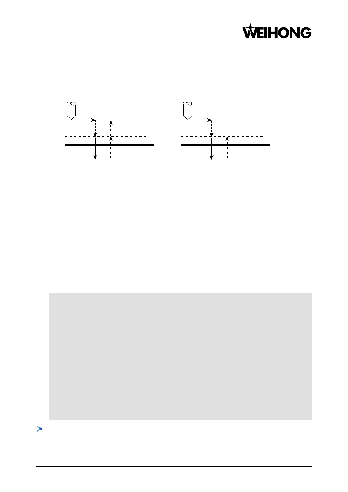
Fig. 4-28 G86 Machining Process
Process Description:
1. The cutter moves to the hole position (X, Y) in G00;
2. Moves down to the specified point R in G00;
3. Moves down to point Z at the bottom of the hole in G01;
4. Drill stops rotating;
5. Retracts to initial point (G98) or point R (G99) in G00;
6. Drill starts to rotate.
Programming Example:
F1200. S600
G90
G00 X0. Y0. Z10. ’moving to the initial point
G17
M03 ’drill CW on
G90 G99
’Specifying the coordinates of point R, point Z and hole 1, with drilling speed as 800
G86 X5. Y5. Z-10. R-5. F800
X25. ’hole 2
Y25. ’hole 3
G98 X5. ’hole 4, and setting to return to initial point
G80
M05 ’drill stop
M02
G87 Fine Back Boring Cycle
This command is not supported at the moment.
Specialized, Concentrated, Focused 41
Page 45
上海维宏电子科技股份有限公司
Point Z
Point R
Initial Point
G98
P
OSS
Spindle CW
OSS
Spindle CW
G99 not in use
Tool
Offset
δ
OSS
(Oriented Spindle Stop)
Weihong Electronic Technology Co., Ltd.
Command Format: G87 X_Y_Z_R_Q_P_F_K_;
Description:
X_Y_: hole position data (absolute/incremental coordinate)
Z_: the position of point Z at the bottom of hole (absolute programming); the distance from point
R to point Z at the bottom of the hole (incremental programming)
R_: the position of point R (absolute programming); the distance from the initial point to point R
(incremental programming)
Q_: displacement of cutter (positive and incremental, minus mark will be ignored)
P_: the dwell time at the bottom of the hole, in ms, with no decimal point
F_: feed speed, even if the canned cycle is cancelled, this modal data is still effective in the
subsequent machining.
K_: number of repeats (repeated movement and drilling, effective under G91 incremental mode)
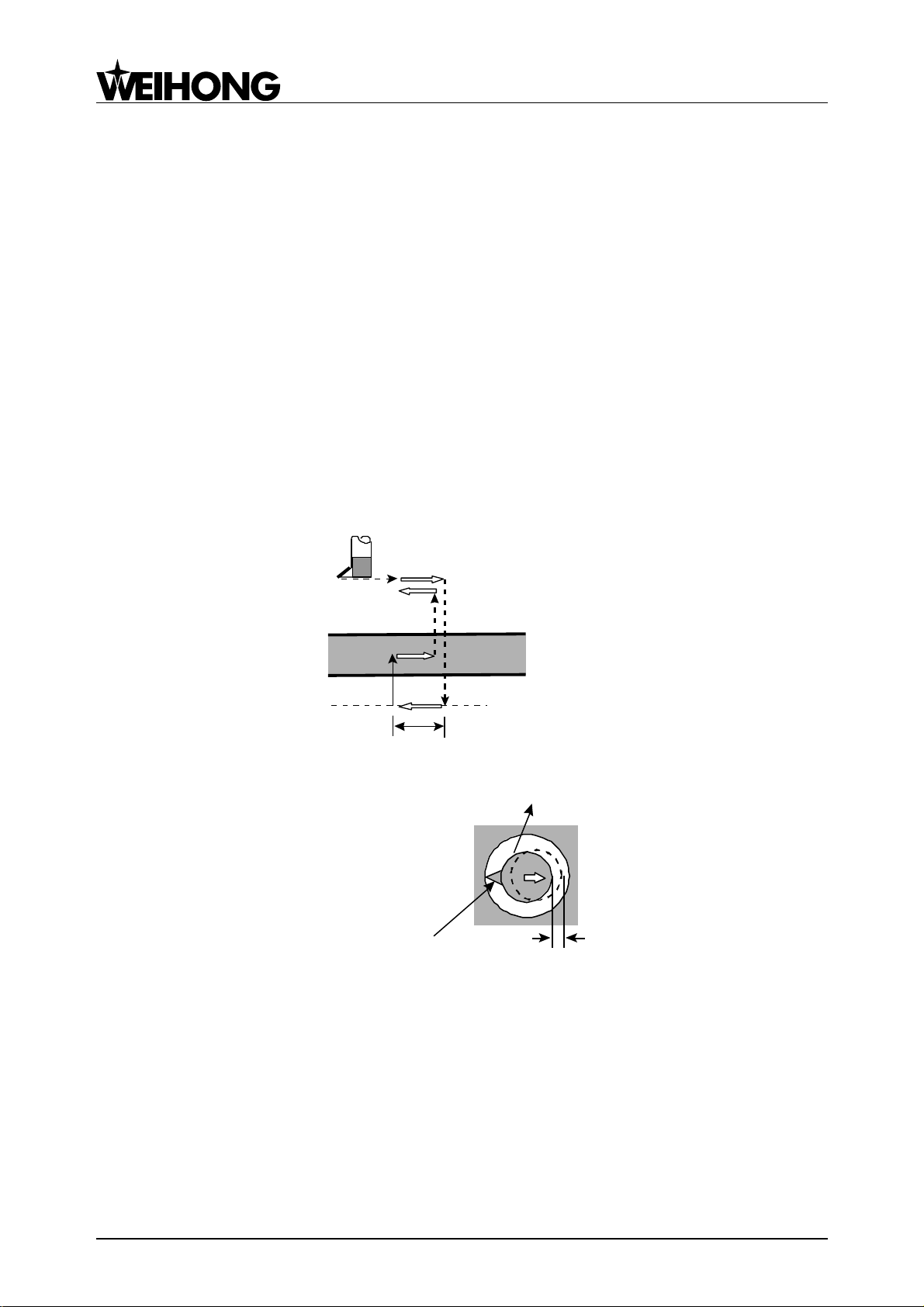
Fig. 4-29 G87 Machining Process
Fig. 4-30 Oriented Spindle Stop (OSS) Sketch Map
Process Description:
1. The cutter moves to the hole position (X, Y) in G00;
2. After OSS, offsets Q distance in a direction opposed to the direction of boring cutter specified
by the parameter ―Oriented Spindle Stop (OSS)‖;
3. Moves down to the specified point R in G00, and offsets Q distance;
4. Spindle CW;
42 Specialized, Concentrated, Focused
Page 46
上海维宏电子科技股份有限公司
Oriented spindle stop (OSS)
G17
G18
G19
0
+X
+Z
+Y 1 -X
-Z
-Y 2 +Y
+X
+Z 3 -Y
-X
-Z
Weihong Electronic Technology Co., Ltd.
5. Retracts to point Z in G01;
6. After P, offsets Q distance in a direction opposed to previous offset;
7. Retracts to the initial point in G00;
8. Offsets Q distance after spindle CW.
※ Alarm:
As a Modal Value requested in G76 cycle, the value of Q must be set carefully, because it is also used
in G73/G83.
OSS (Oriented Spindle Stop) direction is decided by the parameter ―Oriented Spindle Stop‖.
Programming Example:
F1200. S600
G90
G00 X0. Y0. Z10. ’moving to the initial point
G17
M03 ’spindle CW on
G90 G98
’Specifying the coordinates of point R, point Z and hole 1, with offset as 5, dwell time as 4s, and
boring speed as 800
G87 X5. Y5. Z-10. R-5. Q5. P4000 F800
X25. ’hole 2
Y25. ’hole 3
X5. ’hole 4, and setting to return to the initial point
G80
M05 ’spindle stop
M02
G88 Boring Cycle
This command is not supported at the moment.
Command Format: G88 X_Y_Z_R_P_F_K_;
Description:
X_Y_: hole position data (absolute/incremental coordinate)
Z_: the position of point Z at the bottom of the hole (absolute programming); the distance from
point R to point Z at the bottom of the hole (incremental programming)
R_: the position of point R (absolute programming); the distance from the initial point to point R
(incremental programming)
Specialized, Concentrated, Focused 43
Page 47
上海维宏电子科技股份有限公司
Z
R
Initial Point
G98
Z
R
Initial Point
G99
Spindle stop after P
Spindle CW
Spindle CW
Spindle stop after P
(X,Y)
(X,Y)
Weihong Electronic Technology Co., Ltd.
P_: the dwell time at the bottom of the hole, in ms, with no decimal point
F_: feed speed, even if the canned cycle is cancelled, this modal data is still effective in the
subsequent machining.
K_: number of repeats (repeated movement and drilling, effective under G91 incremental mode)
Fig. 4-31 G88 Machining Process
Process Description:
1. The cutter moves to the hole position (X, Y) in G00;
2. Moves down to the specified point R in G00;
3. Moves down to point Z at the bottom of the hole in G01;
4. Spindle stop after P;
5. Retracts to point R in G01;
6. Retracts to initial point (G98) or point R (G99) in G00;
7. Spindle CW.
Programming Example:
F1200. S600
G90
G00 X0. Y0. Z10. ’moving to the initial point
G17
M03 ’spindle CW on
G90 G99
’Specifying the coordinates of point R, point Z and hole 1, with dwell as 2(s), boring speed as 800
G88 X5. Y5. Z-10. R-5. P2000 F800
X25. ’hole 2
Y25. ’hole 3
G98 X5. ’hole 4, and setting to return to the initial point
G80
M05 ’spindle stop
M02
44 Specialized, Concentrated, Focused
Page 48
上海维宏电子科技股份有限公司
Z
R
Initial Point
G98
Z
R
Initial Point
G99
P
P
(X,Y)
(X,Y)
Weihong Electronic Technology Co., Ltd.
G89 Boring Cycle of Dwell at the Bottom of Hole
Command Format: G89 X_Y_Z_R_P_F_K_;
Description:
X_Y_: hole position data (absolute/incremental coordinate)
Z_: the position of point Z at the bottom of the hole (absolute programming); the distance from
point R to point Z at the bottom of the hole (incremental programming)
R_: the position of point R (absolute programming); the distance from the initial point to point R
(incremental programming)
P_: the dwell time at the bottom of the hole, in ms, with no decimal point
F_: feed speed, even if the canned cycle is cancelled, this modal data is still effective in the
subsequent machining.
K_: number of repeats (repeated movement and drilling, effective under G91 incremental mode)
Fig. 4-32 G89 Machining Process
Process Description:
1. The cutter moves to the hole position (X, Y) in G00;
2. Moves down to the specified point R in G00;
3. Moves down to point Z at the bottom of the hole in G01;
4. Pauses for P;
5. Retracts to point R in G01;
6. Retracts to initial point (G98) or point R (G99) in G00.
Programming Example:
F1200. S600
G90
G00 X0. Y0. Z10. ’moving to the initial point
G17
M03 ’spindle CW on
G90 G99
’Setting coordinates of point R, point Z and hole 1, with dwell as 2.5s, machining speed as 800
G89 X5. Y5. Z-10. R-5. P2500 F800
Specialized, Concentrated, Focused 45
Page 49

上海维宏电子科技股份有限公司
G34/35/36/37 instruction error: special canned cycle instructions do not match, with no designation.
Weihong Electronic Technology Co., Ltd.
X25. ’hole 2
Y25. ’hole 3
G98 X5. ’hole 4, and setting to return to the initial point
G80
M05 ’spindle stop
M02
Special Canned Cycle
Description:
Unit of length: millimeter (mm)
Unit of angle: degree
1 meter=1000mm, one full circle= 360 degrees
Special canned cycle instructions (G34-37) must be used together with standard canned cycle
instructions (G73-89).
For Example:
G81 Z-20 R-5 F100 K0
G34 X10 Y10 I10 J90 K10
Standard canned cycle instructions must be written before special canned cycle instructions;
when the execution of a special canned cycle instruction is finished, the standard canned cycle
instruction remains effective until canceled.
For Example:
G81 Z-20 R-5 F100 K0 ’specifying the cycle action
G34 X10 Y10 I10 J90 K10 ’drilling10 holes around a circle
X100 ’drilling another hole, not influenced by the previous G34
If there is no standard canned cycle instruction when executing a special canned cycle instruction,
the system will report an error.
If the following instructions are executed:
G0 X0 Y0 Z0
G34 X10 Y10 I10 J90 K10
…
An error prompt as following will pop up:
A correct form should be like:
G0 X0 Y0 Z0
G81 Z-20 R-5 F100 K0
G34 X10 Y10 I10 J90 K10
…
46 Specialized, Concentrated, Focused
Page 50
上海维宏电子科技股份有限公司
10 20 30-10
10
20
30
-10
θ
N001 G91 G81 G99 Z-5 R6 F500 K1
N002 G34 X10 Y10 I20 J45 K8
The machine tool starts drilling from
position 1 until to position 8.
The included angle is θ between position 1
and positive direction of X axis. Drilling
actions are specified by G81 in program
block N001.
1
2
3
4
5
6
7
8
Weihong Electronic Technology Co., Ltd.
G34 Bolt Hole Circle
Command Format: G34 Xx Yy Ir Jθ Kn
Description:
Drills a circular pattern of a specified number of holes.
X, Y: the center position of this cycle (G90/91 is influential)
I: circle radius r
J: θ, the included angle between X-axis and the point to be drilled first
K: number of holes, within -9999~9999. If the number is 0, an error report will be given. If the
number is greater than 0, hole drilling is CW, but if smaller than 0, hole drilling is CCW.
G34 drills n evenly-spaced holes on one circle with X & Y as center and r as radius, with included
angle as θ between X axis and first hole position, G0 speed employed from one hole to another one.
Fig. 4-33 Sketch Map of Bolt Hole Circle
G35 Holes on Line at Angle Cycle
Command Format: G35 Xx Yy Id Jθ Kn
Description:
Drills holes on a line at an angle with respect to X-axis.
X, Y: the initial position to be drilled (G90/91 is influential)
I: distance (d) between adjacent holes. If the value is minus, drilling holes in symmetry direction.
J: angle θ, specifying the angle of the line holes to be drilled on.
K: number of holes, within 0~9999. If the number is 0, an error report will be given.
G35 drills n evenly-spaced holes on a line at an angle with respect to X axis, with X and Y as
initial position, d as spacing distance between adjacent holes, G0 speed adopted when moving from
one hole to another one.
Specialized, Concentrated, Focused 47
Page 51
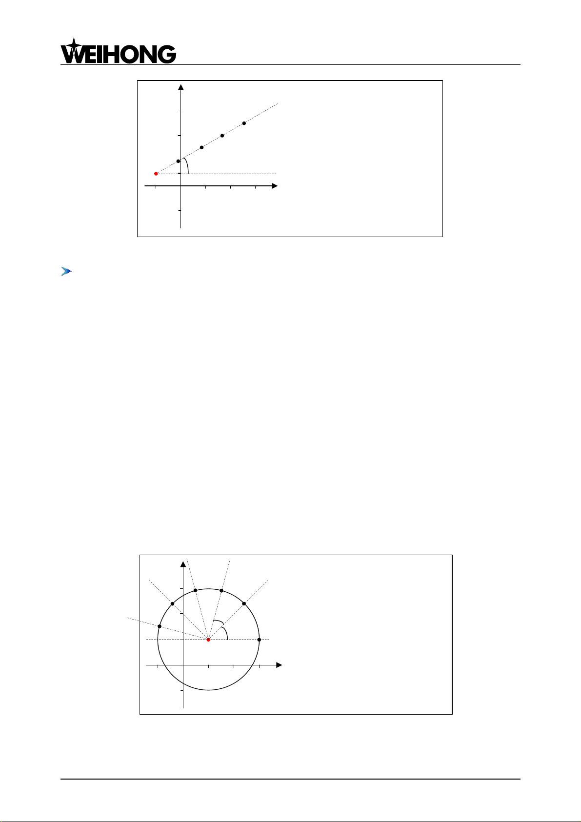
上海维宏电子科技股份有限公司
N001 G91 G81 G99 Z5 R6 F500 K1
N002 G35 X-10 Y5 I10 J60 K8
The machine tool moves from initial point to
position 1, and then drills holes sequentially
from position 1 until to position 5.
Drilling actions are specified by G81 in
program block N001.
10
20
30
-10
10 20 30-10
5
θ
1
2
3
4
5
10 20 30-10
10
20
30
-10
θ
N001 G91 G81 G99 Z-5 R6 F500 K1
N002 G36 X10 Y10 I20 J45 P30 K5
The machine tool drills holes from position 1
until to position 8.
The included angle is θ between position 1
and the positive direction of X axis. Drilling
actions are specified by G81 in program
block N001.
1
2
3
4
5
8
△
θ
Weihong Electronic Technology Co., Ltd.
Fig. 4-34 Sketch Map of Angular Straight Line Drilling Cycle
G36 Arc Drilling Cycle
Command Format: G36 Xx Yy Ir Jθ PΔθ Kn
Description:
Drilling evenly-spaced holes on a circle with specified angle between adjacent holes.
X, Y: center position of this cycle (G90/91 is influential)
I: circle radius r
J: θ, the included angle between the first point to be drilled and X-axis
K: number of holes, within -9999~9999. If the number is 0, an error report will be given. If the
number is greater than 0, hole drilling will be clock-wise, but if smaller than 0, hole drilling will be
counter-clockwise.
G36 drills n evenly-spaced holes on a circle with X, Y as center and r as radius, at the same time,
the included angle is θ between the first drilling point and X-axis, and the angle between adjacent
holes is Δθ, G0 speed used when moving one hole to another one.
The only difference between G36 and G34 is that the former one specifies the included angle
between two holes.
Fig. 4-35 Sketch Map of Arc Drilling Cycle
48 Specialized, Concentrated, Focused
Page 52
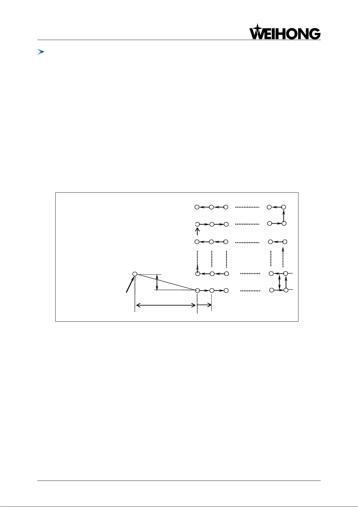
上海维宏电子科技股份有限公司
N001 G91 G81 G99 Z-5 R6 F500 K1
N002 G37 X300 Y-100 I50 P10 J100 K15
Machine tool moves from P, first to A, then drills 10
holes with hole interval as 50mm in X-axis until to
B, then moves 100mm in Y+ direction to C, and
then drills 10 holes until to D in X axis. The rest can
be done in the same manner until J is reached with
15*10 holes drilled. Drilling action is specified by
G81 of program block N001.
X11=300m
y1=100mm
△x=50mm
Position before Execting G37
B
A
D
C
F
E
G
J
H
I
P
△y=100mm
Weihong Electronic Technology Co., Ltd.
G37 Chessboard Hole Cycle
Command Format: G37 Xx Yy IΔx Pnx JΔy Kny
Description:
Chessboard hole cycle.
X, Y: the first position to be drilled (G90/91 is influential)
I: hole interval in X axis
P: number of holes in X axis
J: hole interval in Y axis
K: number of holes in Y axis
G37 drills P*K holes in XY plane with XY as start position. The space between adjacent holes is
Δx in X axis, while in Y axis, the space is Δy, G0 speed used when moving from one hole to another
one.
Fig. 4-36 Demonstration for Chess Hole Cycle Drilling
Customized Canned Cycle
The user can customize G coeds by writing a subprogram in public.dat.
Subprogram no. 200~999 is used by internal parse engine. The code range of M command is
200~599, while that of G code is 600~999.
Therefore, G code (0~99) plus 600 is regarded as the corresponding subprogram.
Specialized, Concentrated, Focused 49
Page 53
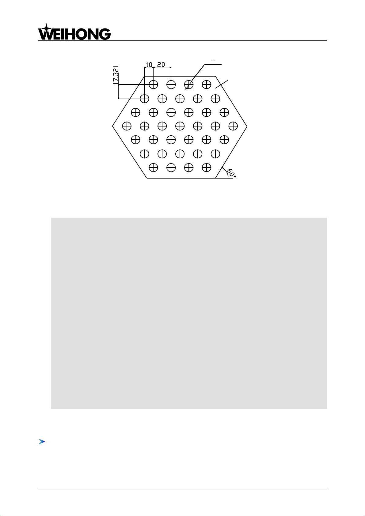
Programming Example:
δ =10
37
Φ
10
Thro ug h hol e
上海维宏电子科技股份有限公司
Weihong Electronic Technology Co., Ltd.
Fig. 4-37 Repeated Canned Cycle Machining
Take a repeated canned cycle to drill holes as shown in Fig. 4-37.
Programming is as following:
N01 G90 X0. Y0. Z100.
N02 G00 X-50. Y51.963 M03 S800
N03 Z20. M08 F4000
N04 G91 G81 X20. Z-18. F4000 R-17. K4
N05 X10. Y-17.321
N06 X-20. K4
N07 X-10. Y-17.321
N08 X20. K5
N09 X10. Y-17.321
N10 X-20. K6
N11 X10. Y-17.321
N12 X20. K5
N13 X-10. Y-17.321
N14 X-20 K4
N15 X10 Y-17.321
N16 X20. K3
N17 G80 M09
N18 G90 G00 Z100.
N19 X0. Y0. M05
N20 M30
G Codes Related with Encoder
G916 Writing Axis Configuration Data Command
Format: G916 PX[_]LX_PY[_]LY_PZ[_]LZ_
Description:
50 Specialized, Concentrated, Focused
Page 54

上海维宏电子科技股份有限公司
Weihong Electronic Technology Co., Ltd.
PX[_], PY[_], PZ[_]: PLC address of to-be triggered latch signals of X, Y and Z axes
LX_, LY_, LZ_: Signal status to trigger latch of X, Y and Z axes
Programming Example:
G916 PX[00000]LX0;
’In the process of homing, encoder zero is used to trigger the latched encoder data. This
instruction informs the drive to write the configuration data of X axis and trigger latch when level
is low.
G918 Clearing Latch Flag Command
Format: G918
Description:
Clears the flag bit of encoder latch of each axis.
Programming Example:
G918;
’Clear the latch flag of encoder of each axis before the encoder latches data. After latch is done,
the flag will be set as 1.
G919 Calculating Deceleration Distance of Cross-signal Trigger Point
Format: G919 H_
Description:
H_: axis No. (0: X axis; 1: Y axis; 2: Z axis) that needs to calculate the deceleration distance from
the triggering point of cross-signal
Programming Example:
G919 H0;
’Calculate the cross-signal deceleration distance of X axis, i.e. the X axis will stop with
deceleration after passing through a waiting signal. This instruction calculates the distance
between triggering point and stop position.
4.4 Advanced Functions
G65 Subroutine Call Command
Command Format: G65 P_ L_
Description:
P: to specify the sequence number or the name of a subprogram to be called
L: times of executing the subprogram
P is used to specify the sequence number or the name of a subprogram to be called in a macro
program. The subprogram will be executed L times. The default value of L is 1.
An argument can be defined in a user macro program if necessary.
The machine tool designer or the user can write some specific programs consisting of a group of
commands in Public.dat, and call them for execution with instruction G65.
Specialized, Concentrated, Focused 51
Page 55
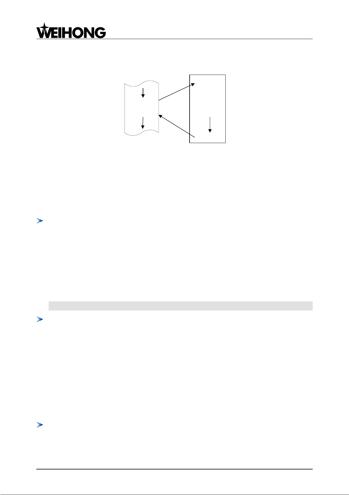
上海维宏电子科技股份有限公司
O"9002"
Operation &
control
instructions
of variable
M17;
G65 P9002 L2
(User-defined
Variable)
Weihong Electronic Technology Co., Ltd.
These specific programs are defined as public subprograms which have the same format as a
subprogram.
Fig. 4-38 Subprogram Call Instruction G65
Fig. 4-38 is a process sketch map to call and execute the subprogram P9002 two times and then
continue executing the following commands.
New function of naming the subprogram is available. The format is O‖subprogram name‖ and
G65 P‖subprogram name‖ L numerical digit (1,2,3…) for writing and calling a subprogram, which is
convenient to remember. Note that a program name can not be Chinese characters.
G903 100% feedrate override command
Command Format: G903
Description:
This instruction sets feedrate override as 100% forcedly, whatever the value the user sets. It is
often used in functions of backing to machine origin and tool measurement to ensure accuracy.
This non-modal command should be used together with G00, G01, G02, or G03.
Programming Example:
G905 G903 G01 X10 Y20 Z0 F600; ’F (feedrate) is set as 600 mm/min forcedly
G904 Conditional Movement Command
Command Format: G904 FX_PX_ LX_ FY_PY_LY_ FZ_PZ_LZ_ X_Y_Z_
Description:
FX_, FY_, FZ_: the moving speed and direction of X, Y and Z axes
PX_, PY_, PZ_: the to-be-detected signal port no. of X, Y and Z axes
LX_, LY_, LZ_: the signal status that is waited to stop movement of X, Y and Z axes (1: on; 0: off)
X_, Y_, Z_: the longest moving distance
Unnecessary axes can be omitted. However, once an axis appears, except X_Y_Z_, the other
data must be complete.
G905 Enable feedrate command
Command Format: G905
Description:
52 Specialized, Concentrated, Focused
Page 56

上海维宏电子科技股份有限公司
Weihong Electronic Technology Co., Ltd.
G905 enables feed speed specified by F command temporarily, instead of the default speed.
When the parameter ―Use default speed‖ is set as valid, this instruction disables the default
speed and forces to use the programmed speed temporarily, commonly used in functions of backing
to reference point and tool measurement, and so on.
This non-modal command is used together with G00, G01, G02 or G03.
Programming Example:
G905 G903 G01 X10 Y20 Z0 F600; ’F (feed speed) is set as 600 mm/min forcedly
G906 Synchronization /Overtime Check
When only used as synchronization function, Command Format: G906
When used as overtime check function, Command Format: G906 PLC [PLCADDRESS]
LEVEL_ P_
Description:
PLC [PLCADDRESS]: PLC address of port; PLC [PLCADDRESS] or PLC=Integer Expression
indicating PLC internal address
LEVEL_: port value (0/1)
P_: wait time, in milliseconds
This instruction is used for synchronization. That is to say, the following operation will go on only
after various parameters are synchronized.
G906 should be executed for synchronization before using the internal system parameters or
instructions concerning modifying system parameters and status, such as G92, M902.
The extended function of G906 is overtime check for a specified port. In the mean time, the
synchronization function is also effective. When G906 is only used for synchronization there are no
parameters after G906. When the extended function is needed, see the following example for the
programming format:
G906 PLC [04] LEVEL1 P1000; ’wait until PLC port 04 is in state 1 and exit after timeout (1000
milliseconds)
G907 Move in the Shortest Path
Command Format: G907
Description:
G907 is used to move in the shortest track under rotary axis mode. This instruction is only
available under rotary axis mode.
G908 Force to Program in Degrees
Command Format: G908
Description:
G908 forces to program in degrees under rotary axis mode. This instruction is only available
Specialized, Concentrated, Focused 53
Page 57

under rotary axis mode.
M801 String Information Command
Command Format: M801_
Description:
This instruction is used for transferring message between modules.
Programming Example:
M801 ―Hello‖ ’transferring ―hello‖
M802 Integer Message Command
Command Format: M802 Pxxxx
Description:
This instruction is used to transfer integer message.
xxxx: integer message to be transferred
上海维宏电子科技股份有限公司
Weihong Electronic Technology Co., Ltd.
For Example:
M802 P196609 close the buffer zone
M802 P196608 open the buffer zone
M802 P131072 limit off
M802 P131073 limit on
M802 P458752 clear external offset. After modifying G codes of fixed tool measurement,
use this command to clear external offset after measurement.
M901 Directly Control Output Port
Command Format: PLC [PLCADDRESS] LEVEL_
Description:
PLC [PLCADDRESS]: PLC address of port; PLC [PLCADDRESS] or PLC = Integer Expression
indicating PLC internal address
LEVEL_: port value (0/1)
Programming Example:
M901 PLC [04] LEVEL1; ’assign 1 to the port 04 (PLC address)
M902 Directly Set REF.
Command Format: M902 Ha
Description:
a: axis address; 0-3 are respectively corresponding to X, Y, Z, and A axes.
Programming Example:
M902 H0; ’end of X-axis returning to reference point, i.e. the machine coordinate of current point
is 0 (machine origin) in X-axis
54 Specialized, Concentrated, Focused
Page 58
上海维宏电子科技股份有限公司
Function
Meaning
Sin
sine
Cos
cosine
exp
exponent
sqrt
square root
log
natural logarithm
tg
tangent
ctg
cotangent
asin
arcsine
acos
arc cosine
atg
arc tangent
int
round-down
abs
absolute value
Weihong Electronic Technology Co., Ltd.
4.5 Expressions Used in Program Instructions
Current Definition for Expression:
All positions behind the address characters that are taken up by numbers can be replaced by
assignment expressions.
No characters of space type are allowed to exist in the expression, including Space, Tab and
Enter, etc. What’s more, an expression must be ended with a valid separator.
Definition for Assignment Expression:
An assignment expression begins with an equal mark, followed by an arithmetic expression
which is constituted by various operators, functions, variables, brackets, etc.
The operators available now are divided into the following seven classes in order of priority:
1. Bracket
2. Function
3. Plus sign +, Minus sign -, NOT !
4. Multiplication *, Division /
5. Addition +, Subtraction –
6. Equal ==, Not equal !=, Greater than >, Less than <
7. OR ||, AND &&
Following are the mathematical functions available now:
Specialized, Concentrated, Focused 55
Page 59
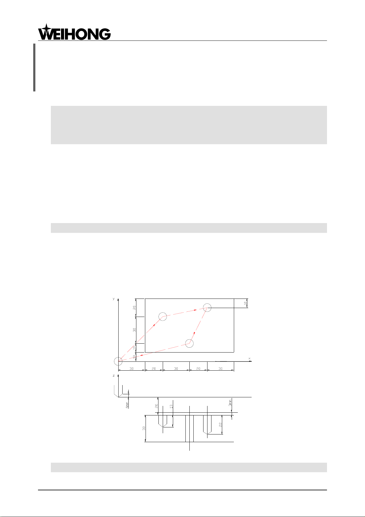
上海维宏电子科技股份有限公司
Weihong Electronic Technology Co., Ltd.
Note:
Radian is the unit for the numbers in the brackets which are behind sin, cos, tg, ctg, asin, acos, atg.
For example: sin (5), 5 represents 5 radians.
Application of Expression in Program Instructions:
Instance one: B=1+2; ’i.e. B=3
Instance two: G00 X3 Y5 Z=5+sin (5+abs (-8)); ’Assign 5+sin (5+abs (-8)) to Z
Instance three: #1=4+log6
G01 X2 Y=#; ’Assign 4+log6 to Y
4.6 Comments in Program
A comment in a program is started with a single quotation mark:
’—— end-of-line pattern, content behind the single quotation mark does not work until the end of
line.
For Example:
G00 X3 Y5 ’rapid traverse to X3, Y5
The content behind the single quotation mark can only act as a comment and will not be
executed when the program is run.
4.7 Demonstration of Machining File Programming
Example 1 Programming for the Workpiece Shown in Fig. 4-39
Fig. 4-39 Workpiece Machining Sketch
N01 G92 X0 Y0 Z0 ’workpiece coordinates system setting
56 Specialized, Concentrated, Focused
Page 60
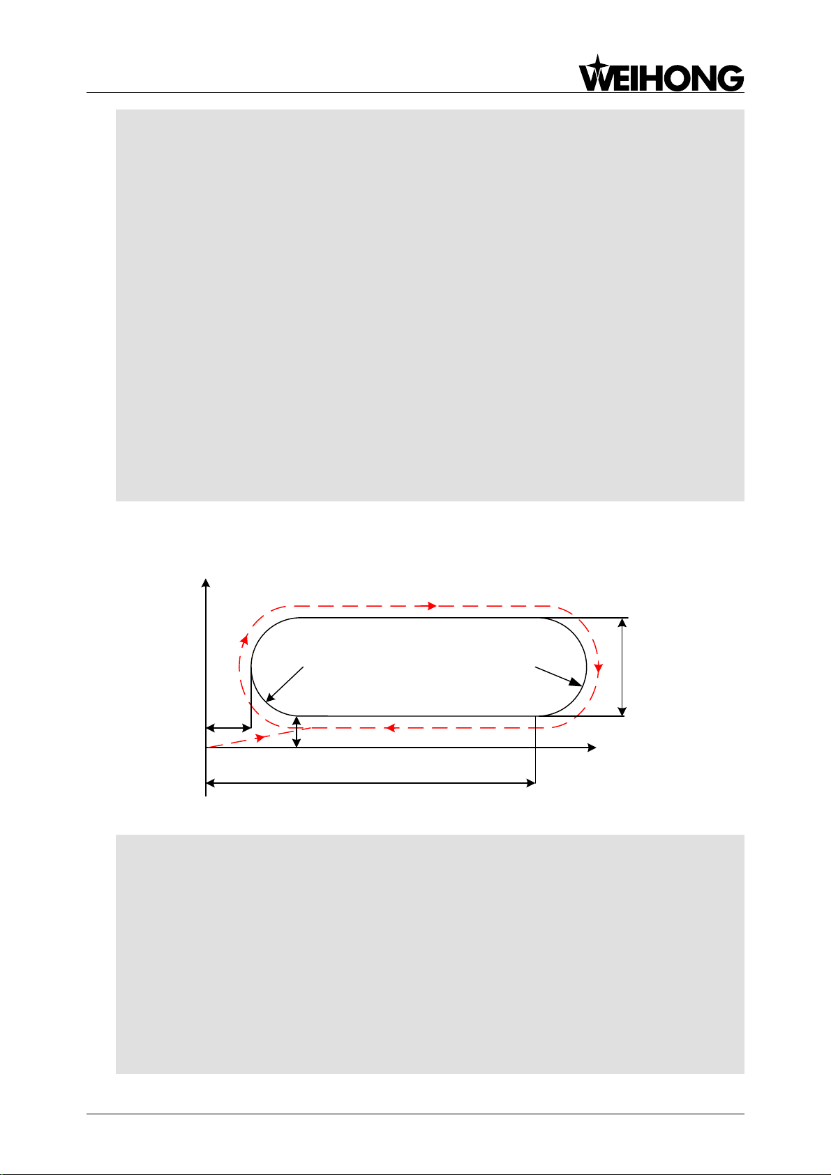
上海维宏电子科技股份有限公司
R25
R25
20
15
135
X
Y
50
Weihong Electronic Technology Co., Ltd.
N02 G91 G00 X50 Y50 M03 S600 M08
’incremental mode selected, the tool moves X50 Y50 at rapid traverse rate, spindle CW at 600
rpm, and coolant on
N03 G43 Z-17 H01 ’rapid traverse 17mm downward in Z axis, length compensation on
N04 G01 Z-16 F400 ’linear interpolation 16mm downward at 400mm/min in Z-axis
N05 G04 P2000 ’dwell for 2s
N06 G00 Z16 ’16mm upward in Z axis at rapid traverse rate
N07 X50 Y10 ’50mm and 10mm towards the positive direction of X axis and Y-axis
respectively at rapid traverse rate
N08 G01 Z-25 ’linear interpolation 25mm downward in Z-axis
N09 G04 P2000 ’dwell for 2s
N10 G00 Z25 ’upward 25mm in Z axis at rapid traverse rate
N11 X-20 Y-40 ’20mm and 40mm in the reverse direction of X axis and Y axis respectively
N12 G01 Z-40 ’linear interpolation 40mm downward in Z-axis
N13 G00 Z57 ’upward 57mm in Z axis at rapid traverse rate
N14 G49 X-80 Y-20 M05 M09 M30
’length compensation cancel, 80mm and 20mm in the reverse direction of X axis and Y axis
respectively, spindle stop, coolant off, end of program and return to the program header
Example 2 Programming for the Workpiece Shown in Fig. 4-40
Fig. 4-40 Workpiece Machining Sketch
N01 G92 X0 Y0 Z0 ’workpiece coordinates system setting
N02 G90 G41 G00 X45 Y15 D01 M03 S600 M08 ’absolute programming adopted, cutter radius
compensation on, rapid traverse to X45, Y15, spindle CW at 600 rpm, and coolant on
N03 G17 G02 X45 Y65 I0 J25 F700
’Clockwise circular interpolation to X45, Y65, radius 25mm, feed speed 700mm/min
N04 G01 X135 Y65 ’linear interpolation until X135, Y65
N05 G17 G02 X135 Y15 I0 J-25 ’CW circular interpolation to X135, Y15, radius 25mm
N06 G01 X45 Y15 ’linear interpolation to X45, Y15
N07 G00 G40 X0 Y0 M05 M09 M30
’Cutter radius compensation cancel, rapid traverse to X0, Y0, spindle stop, coolant off, end of
program and return to the program header
Specialized, Concentrated, Focused 57
Page 61
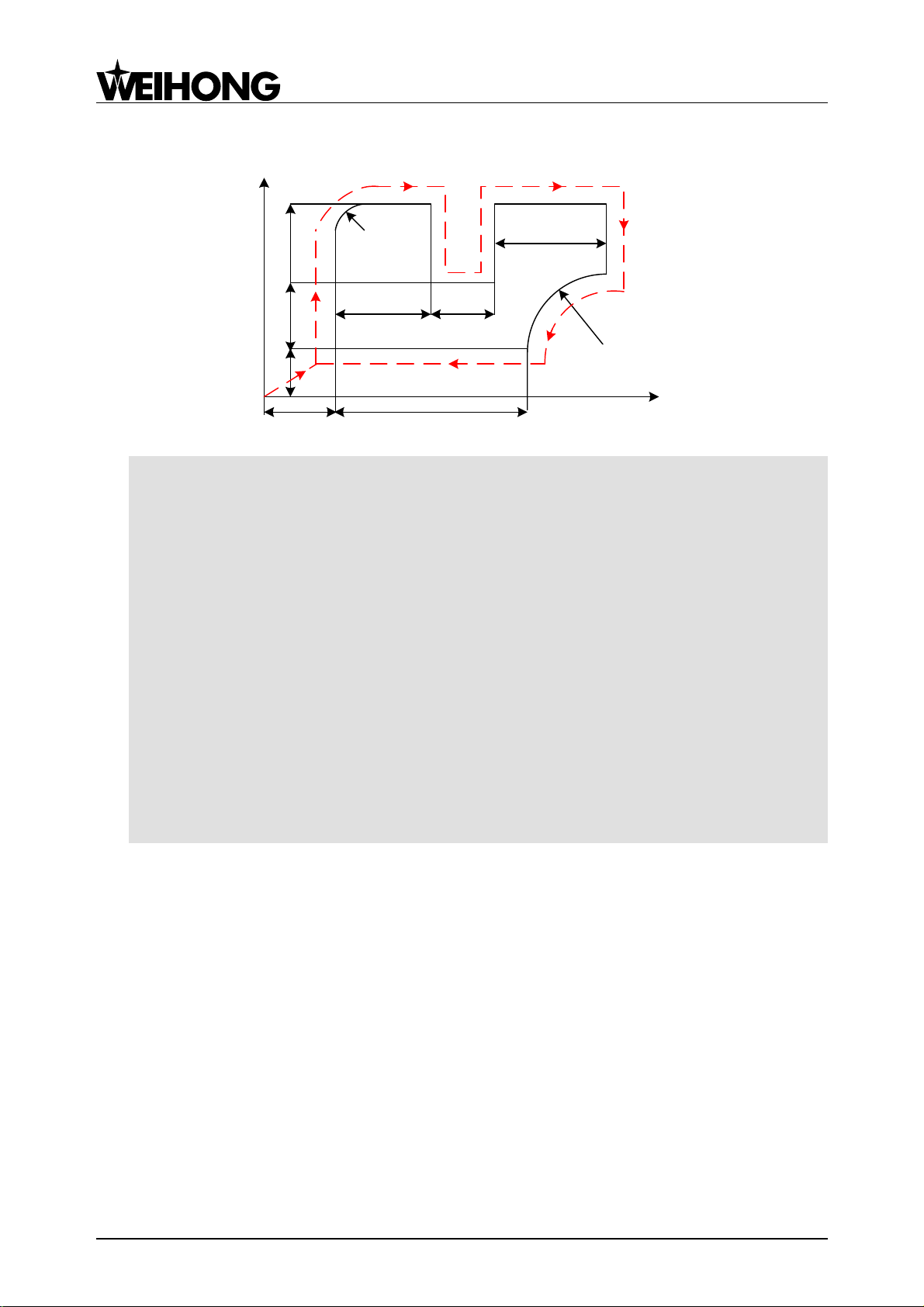
上海维宏电子科技股份有限公司
60 40
70
50
40
30
40 120
Y
X
R20
R50
Weihong Electronic Technology Co., Ltd.
Example 3 Programming for the Workpiece Shown in Fig. 4-41
Fig. 4-41 Workpiece Machining Sketch
N01 G92 X0 Y0 Z0 ’workpiece coordinates system establishment
N02 G91 G41 G00 X40 Y30 D01 M03 S600 M08 ’incremental coordinates adopted, cutter
radius compensation on, rapid traverse to X40, Y30, spindle CW at 600 rpm, and coolant on
N03 G17 G01 X0 Y70 F800 ’linear interpolation to X40, Y100, feed speed 800mm/min
N04 G02 X20 Y20 I20 J0 ’clockwise circular interpolation to X60, Y120, radius 20mm
N05 G01 X40 ’linear interpolation 40mm in the positive direction of X-axis
N06 Y-50 ’linear interpolation 50mm in the reverse direction of Y-axis
N07 X40 ’linear interpolation 40mm in the positive direction of X-axis
N08 Y50 ’linear interpolation 50mm in the positive direction of Y-axis
N09 X70 ’linear interpolation 70mm in the positive direction of X-axis
N10 Y-40 ’linear interpolation 40mm in the reverse direction of Y-axis
N11 G03 X-50 Y-50 I0 J-50 ’counterclockwise circular interpolation to X160, Y30, radius 50mm
N12 G01 X-120 ’linear interpolation 120mm in the reverse direction of X-axis
N13 G00 G40 X-40 Y-30 M05 M09 M30
’Cutter radius compensation cancel, rapid traverse to X0, Y0, spindle stop, coolant off, end of
program and return to the program header
58 Specialized, Concentrated, Focused
Page 62
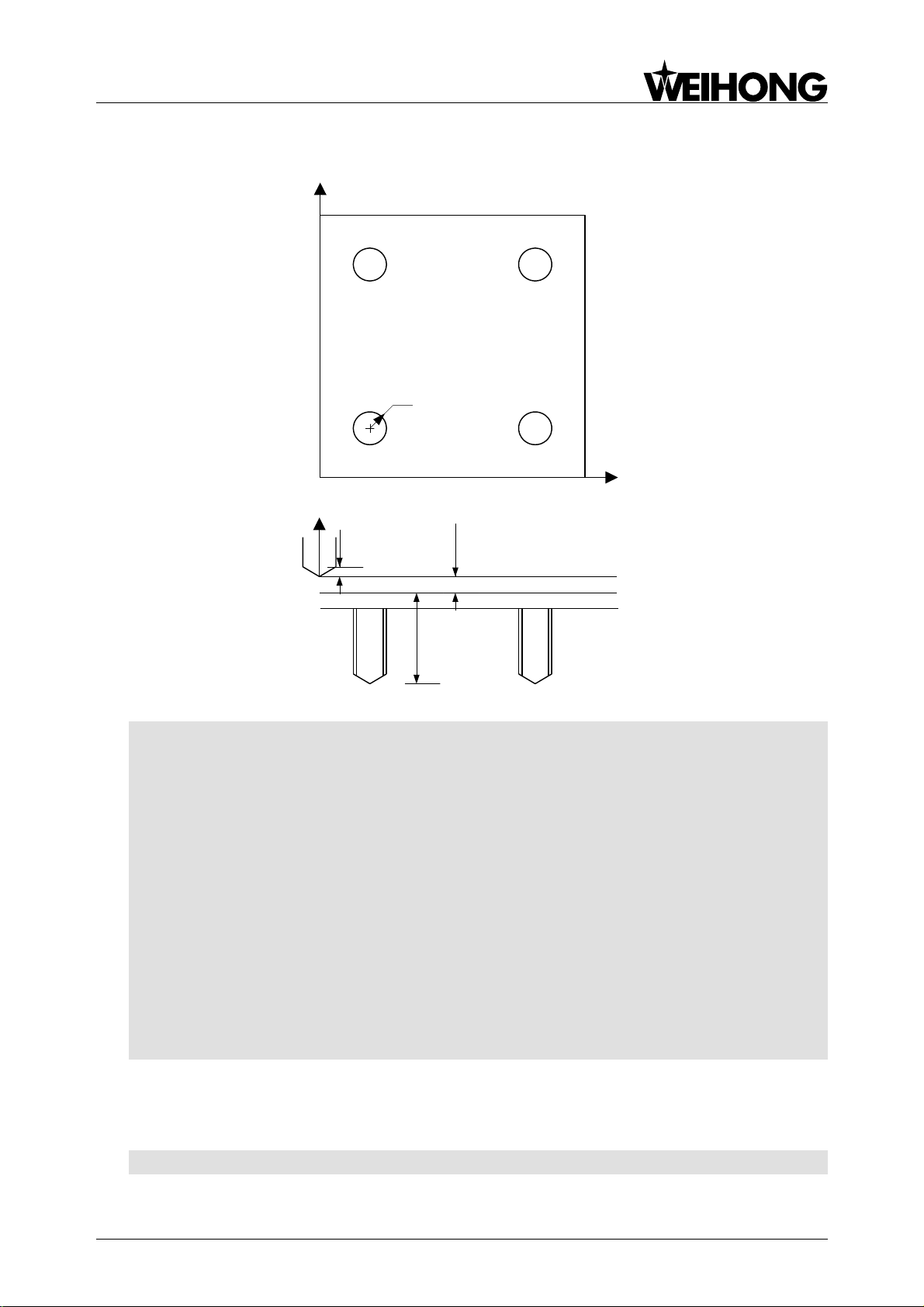
上海维宏电子科技股份有限公司
Y
X
Z
15 65 80
15
R 5
0
0
28
5
3
65
Weihong Electronic Technology Co., Ltd.
Example 4 Programming for the Workpiece Shown in Fig. 4-42 (CCW tapping)
Fig. 4-42 Workpiece Machining Sketch
N01 G92 X0 Y0 Z0 ’workpiece coordinates system establishment
N02 G91 G00 X-35 Y15 M04 S600 M08
’Incremental coordinates adopted, rapid traverse to X-35, Y15, spindle CCW at 600 rpm, and
coolant on
N03 G43 G00 Z0 H01 ’cutter length compensation on
N04 G74 X50 Y0 Z-28 R-5 P1000 F1000 L2
’CCW tapping at 1000mm/min, tapping depth 28mm, dwell for 1s at the bottom of the hole,
executed twice
N05 G00 X-50 Y50 ’rapid traverse to X15, Y65, and start tapping
N06 G00 X50 ’rapid traverse to X65, Y65, and start tapping
N07 G80 ’hole machining cancel
N08 G00 X-65 Y-65 ’rapid traverse to X0, Y0
N09 G49 M05 M09 M30 ’length compensation cancel, spindle stop, coolant off, end of
program and return to the program header
Example 5 Programming for the Workpiece Shown in Fig. 4-43 (requirement: amount of feed is
2mm each time in Z-axis)
N01 G92 X0 Y0 Z0 ’workpiece coordinates system establishment
Specialized, Concentrated, Focused 59
Page 63
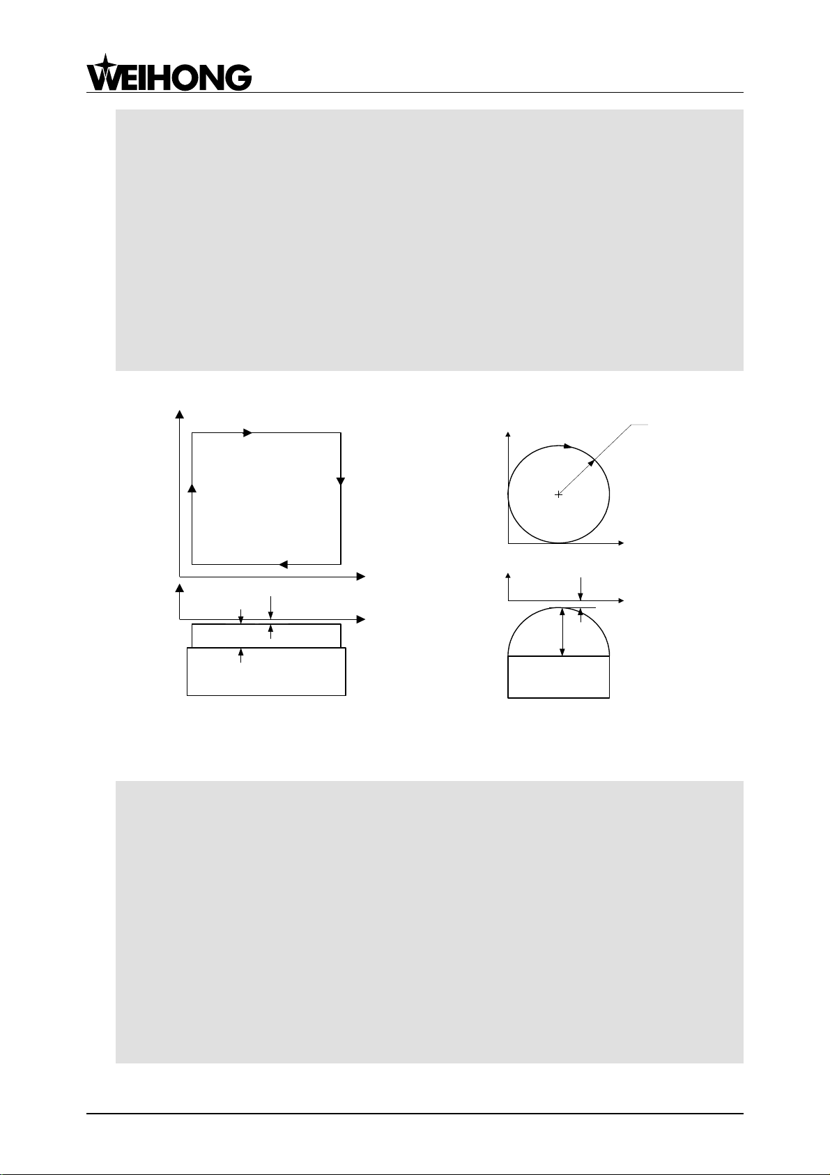
上海维宏电子科技股份有限公司
Y
X
Z
X
60
60
10
2
10
Z
Y
X
X
R 14
14
2
0
0
Weihong Electronic Technology Co., Ltd.
N02 G91 M03 S800 M08 ’incremental coordinates adopted, spindle CW at 800 rpm, coolant on
N03 G65 P9001 L6 ’subprogram 9001 call, executed six times
N04 G00 Z12 M05 M09 M30 ’rapid traverse to X0, Y0, Z0, spindle stop, coolant off, end of
program and return to the program header
O9001 ’subprogram 9001
N100 G00 X10 Y0 Z-2 ’rapid traverse to X10, Y0, Z-2
N110 G01 Y60 F1000 ’linear interpolation to X10, Y60, feed speed 1000mm/min
N120 X50 ’linear interpolation to X60, Y60
N130 Y-50 ’linear interpolation to X60, Y10
N140 X-60 ’linear interpolation to X0, Y10
N150 G00 Y-10 ’rapid traverse to X0, Y0
N160 M17 ’subprogram return
Fig. 4-43 Workpiece Machining Sketch Fig. 4-44 Workpiece Machining Sketch
Example 6 Programming for the Workpiece shown in Fig. 4-44.
N01 G92 X10 Y0 Z0 ’workpiece coordinates system establishment
N02 G91 G00 X-10 M03 S1000 M08
’Incremental coordinates adopted, spindle CW at 1000 rpm, and coolant on
N03 G00 Y14 Z-16 ’rapid traverse to X0 Y14 Z-16
N04 G02 X0 Y0 I14 J0 F600 ’clockwise circular interpolation, feed speed 600mm/min
N05 G01 X1 Z1 F600 ’linear interpolation, advance 1mm along both X-axis and Z-axis
N06 G02 X0 Y0 I13 J0 F600
N07 G01 X1 Z1 F600
N08 G02 X0 Y0 I12 J0 F600
N09 G01 X1 Z1 F600
N10 G02 X0 Y0 I11 J0 F600
N11 G01 X1 Z1 F600
N12 G02 X0 Y0 I10 J0 F600
60 Specialized, Concentrated, Focused
Page 64
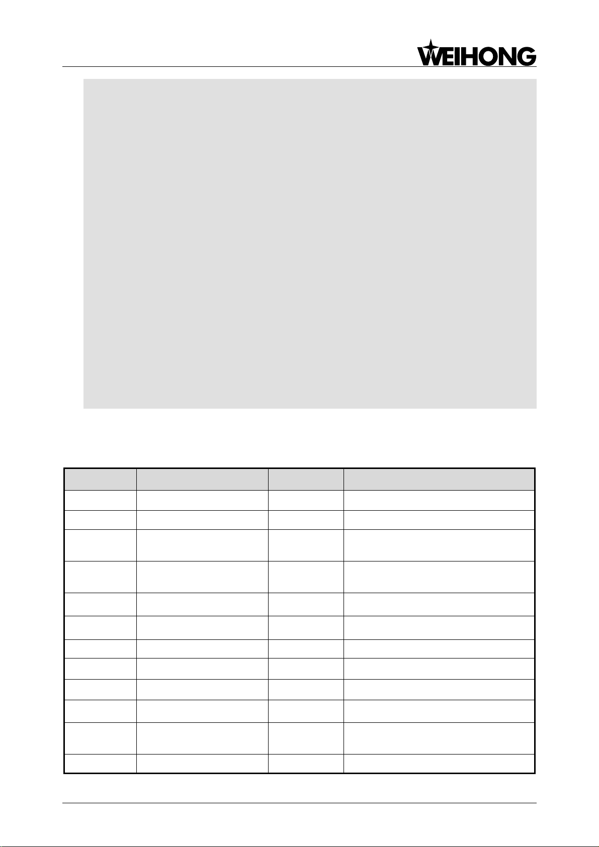
上海维宏电子科技股份有限公司
G code
Function
G code
Function
G00
Rapid positioning
G65
Subprogram call
G01
Linear interpolation
G68
Coordinate system rotation
G02
Circular interpolation
(clockwise)
G69
Cancel coordinate system rotation
G03
Circular interpolation
(counterclockwise)
G70
Input in inch
G04
Dwell
G71
Input in mm
G17
XY plane selection
G73
High speed peck drill cycle
G18
ZX plane selection
G74
Left tapping cycle
G19
YZ plane selection
G76
Fine boring cycle
G20
Input in inch
G80
Cancel canned cycle
G21
Input in mm
G81
Drilling cycle
G28
Return to reference
position
G82
Drilling cycle of dwell at the bottom of
hole
G34
Bolt hole circle
G83
Peck drilling cycle (for deep holes)
Weihong Electronic Technology Co., Ltd.
N13 G01 X1 Z1 F600
N14 G02 X0 Y0 I9 J0 F600
N15 G01 X1 Z1 F600
N16 G02 X0 Y0 I8 J0 F600
N17 G01 X1 Z1 F600
N18 G02 X0 Y0 I7 J0 F600
N19 G01 X1 Z1 F600
N20 G02 X0 Y0 I6 J0 F600
N21 G01 X1 Z1 F600
N22 G02 X0 Y0 I5 J0 F600
N23 G01 X1 Z1 F600
N24 G02 X0 Y0 I4 J0 F600
N25 G01 X1 Z1 F600
N26 G02 X0 Y0 I3 J0 F600
N27 G01 X1 Z1 F600
N28 G02 X0 Y0 I2 J0 F600
N29 G01 X1 Z1 F600
N30 G02 X0 Y0 I1 J0 F600
N31 G90 G00 X0 Y0 Z0 M05 M09 M30
’Rapid traverse to X0, Y0, Z0, spindle stop, coolant off, end of program and return to the program
header
4.8 G Command Appendix
The appendix of G codes is as shown below:
Specialized, Concentrated, Focused 61
Page 65
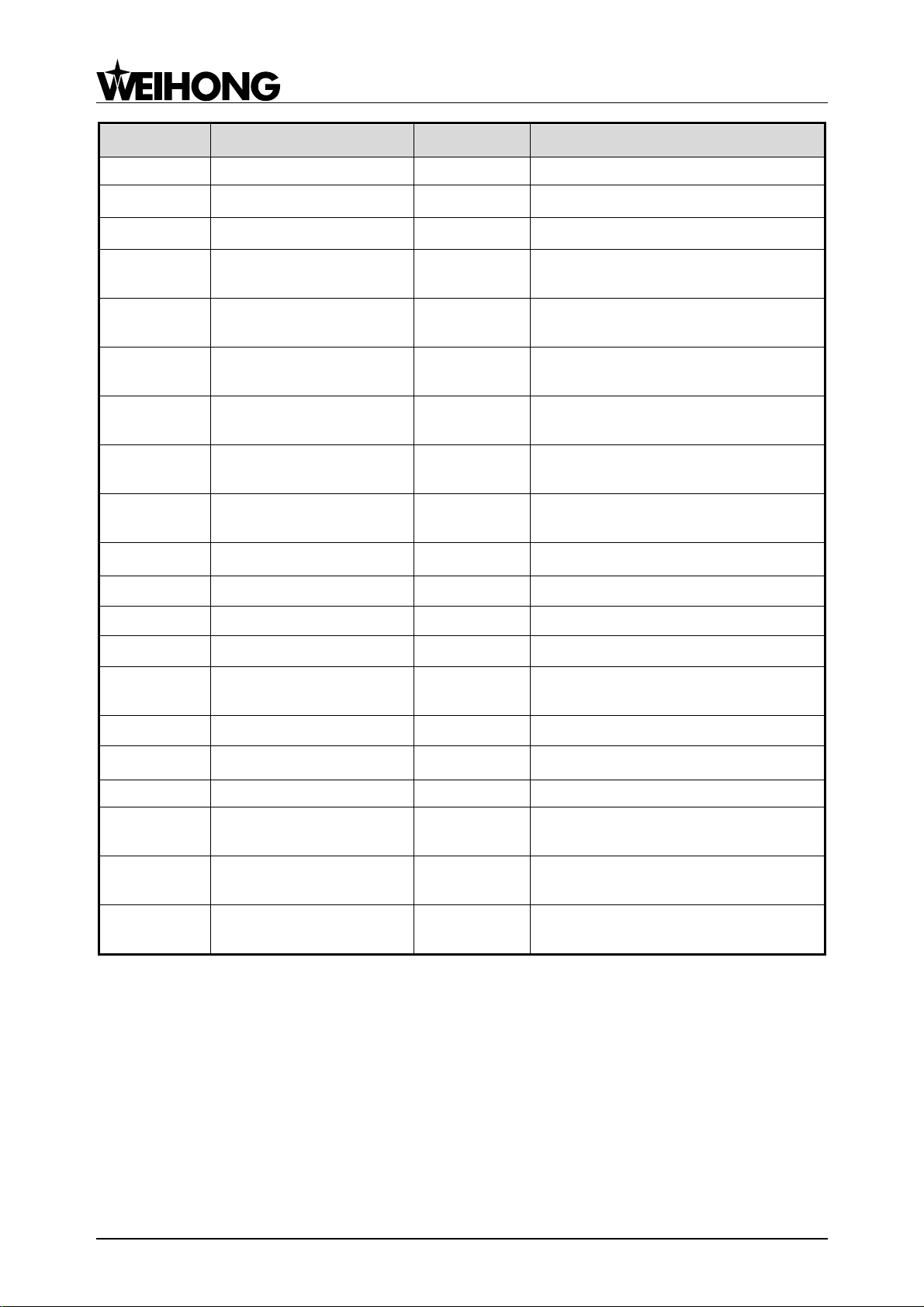
上海维宏电子科技股份有限公司
G code
Function
G code
Function
G35
Line at angle drilling cycle
G84
Tapping cycle
G36
Arc drilling cycle
G85
Drilling cycle
G37
Chessboard hole cycle
G86
High speed drilling cycle
G40
Cancel cutter radius
compensation
G87
Fine Back boring cycle
G41
Left cutter radius
compensation
G88
Boring cycle
G42
Right cutter radius
compensation
G89
Boring cycle of dwell at the bottom of
hole
G43
Tool length positive
compensation
G90
Absolute coordinate programming
G44
Tool length negative
compensation
G91
Incremental coordinate programming
G49
Cancel tool length
compensation
G92
Set WCS according to tool position
G50
Scaling off
G98
Return to initial point
G51
Scaling on
G99
Return to point R
G50.1
Mirror image off
G903
100% feedrate override command
G51.1
Mirror image on
G904
Conditional movement command
G53
Machine coordinate
system
G905
Enable feedrate command
G54
WCS 1
G906
Synchronization command
G55
WCS 2
G907
Move in the shortest path
G56
WCS 3
G908
Force to program in degrees
G57
WCS 4
G921
Specify work coordinate value of
current point
G58
WCS 5
G922
Specify WCS origin (including external
offset)
G59
WCS 6
G992
Temporarily set WCS according to tool
position
Weihong Electronic Technology Co., Ltd.
62 Specialized, Concentrated, Focused
Page 66

上海维宏电子科技股份有限公司
Weihong Electronic Technology Co., Ltd.
5 Named Parameters
For a common user, the machining workpiece operations and other basic operations provided by
the controller can meet his demands, such as: tool calibration, center calibration, canned cycle, etc.
While for an advanced user who needs to modify some operating details, write operating
programs and customize canned cycles, the controller provides a group of fast and convenient
named parameters. With these parameters, it is not only convenient for the user to modify or write
operation programs and customize the content of canned cycle in public.dat to meet the machining
demand, but also convenient to write programs directly in the program edit operation interface.
Example 1, Use named parameters to compile a subprogram of tool coolant and tool change, as
follows:
O1000 ’subprogram of tool coolant and tool change
M901 H=#COOLANT_START_PORT P1
G04 P10
IF(#ENABLE_CTP) G53 G00 G90 X=#CTP_POS.X Y=#CTP_POS.Y Z=#CTP_POSZ ’move to
the position of tool change
G00 G90 Z10 ’or lift the cutter directly for tool change
M05
M17
Example 2, Use named parameters to modify the content of G86 canned cycle from without
retract amount parameter in the system to with retract amount parameter, as follows:
O686
#FC50=#CANNEDCYCLE_BACK
IF (! #FC13) G90 G65 P786
IF (#FC13) G91 G65 P786 L=#FC11
M17
O786
G00 X=#FC1 Y=#FC2
G90 G00 Z=#FC4
G90 G01 Z=#FC4-ABS (#FC5) F=#FC7
G65 P886 L=INT(ABS(#FC4-#FC3)/ABS(#FC5)) -1
G90 G01 Z=#FC3 F=#FC7
M05
G90 G00 Z=#FC4
IF (!#FC12)G90 G00 Z=#FC14
M03
IF (#FC13) G91
M17
O886
Specialized, Concentrated, Focused 63
Page 67
上海维宏电子科技股份有限公司
No.
Parameter
Parameter Name
Type
Remarks
01
CURMACHPOS.X
Mechanical
coordinate of current
point (X axis)
DOUBLE
Mechanical coordinate of current
point (X axis)
02
CURMACHPOS.Y
Mechanical
coordinate of current
point (Y axis)
DOUBLE
Mechanical coordinate of current
point (Y axis)
03
CURMACHPOS.Z
Mechanical
coordinate of current
point (Z axis)
DOUBLE
Mechanical coordinate of current
point (Z axis)
04
CURWORKPOS.X
Workpiece coordinate
of current point (X
axis)
DOUBLE
Workpiece coordinate of current
point (X axis)
05
CURWORKPOS.Y
Workpiece coordinate
of current point (Y
axis)
DOUBLE
Workpiece coordinate of current
point (Y axis)
06
CURWORKPOS.Z
Workpiece coordinate
of current point (Z
axis)
DOUBLE
Workpiece coordinate of current
point (Z axis)
07
INPORTMAP
Mapping of port input
INT
Status of port input
08
OUTPORTMAP
Mapping of port
output
INT
Status of port output
09
SAFEHEIGHT
Safe height
DOUBLE
This height is relative to the
workpiece origin, and only valid
during backing to workpiece
origin and resuming breakpoint.
10
ISYREVAXIS
Y axis as the rotary
axis
BOOL
Whether to set Y as rotary axis
11
WPREVDIAM
Diameter of rotary
workpiece
DOUBLE
Diameter of rotary workpiece
being currently machined
Weihong Electronic Technology Co., Ltd.
G91 G00 Z=#FC50
G91 G00 Z=-#FC50
G91 G01 Z=-ABS (#FC5) F=#FC7
M17
The variables defined in the canned cycle and their meanings:
X--#FC1---- X-coordinate of the hole center
Y--#FC2---- Y-coordinate of the hole center
Z--#FC3---- workpiece coordinate of Z plane (hole depth, negative)
R--#FC4---- workpiece coordinate of R plane (changing from the rapid traverse speed to the
cutting speed in R plane, >0)
Q--#FC5---- cutting depth each time (incremental and positive); offset value in G76/G87
G99/G98--#FC12---G99->1; G98->0
G90/G91--#FC13---G91->1; G90->0
Z0--#FC14---Initial point height
The list of named parameters is as shown blow:
64 Specialized, Concentrated, Focused
Page 68
上海维宏电子科技股份有限公司
No.
Parameter
Parameter Name
Type
Remarks
12
UNIT.YR
Programming unit of
rotary axis
INT
0:angle (unit: radian)
1: surface distance of rotary
workpiece (unit: millimeter)
13
AUTOSTOPSPIN
DLE
Spindle stop when
stop
BOOL
Whether to stop spindle
automatically after machining
finishes
14
SPINDLE_DELAY
Delay when spindle
On/ Off
DOUBLE
Setting the delay time when
spindle starts/ stops automatically
15
MOBICALI_THICK
NESS
The thickness of tool
presetter in mobile
tool measurement
DOUBLE
Setting the thickness of tool
presetter in mobile tool
measurement
16
FIXEDCALI_POS.
X
The position of tool
presetter in fixed tool
measurement (X-axis)
DOUBLE
The mechanical coordinate of the
position where tool presetter
stands (X-axis) in fixed tool
measurement
17
FIXEDCALI_POS.
Y
The position of tool
presetter in fixed tool
measurement (Y-axis)
DOUBLE
The mechanical coordinate of the
position where tool presetter
stands (Y-axis) in fixed tool
measurement
18
FIXEDCALI_POS.
Z
The position of tool
presetter in fixed tool
measurement (Z-axis)
DOUBLE
The mechanical coordinate of the
position where tool presetter
stands (Z-axis) in fixed tool
measurement
19
ENABLE_CTP
Back to fixed point
valid
BOOL
Back to fixed point after the
program ends normally.
20
CTP_POS.X
The position of fixed
point (X axis)
DOUBLE
Mechanical coordinate of fixed
point(X axis)
21
CTP_POS.Y
The position of fixed
point (Y axis)
DOUBLE
Mechanical coordinate of fixed
point(Y axis)
22
CTP_POS.Z
The position of fixed
point (Z axis)
DOUBLE
Mechanical coordinate of fixed
point(Z axis)
23
BKREF_SW1.X
Port no. input of
X-axis coarse
positioning switch
INT
The signal port input of X-axis
coarse positioning switch
24
BKREF_SW1.Y
Port no. input of
Y-axis coarse
positioning switch
INT
The signal port input of Y-axis
coarse positioning switch
25
BKREF_SW1.Z
Port no. input of
Z-axis coarse
positioning switch
INT
The signal port input of Z-axis
coarse positioning switch
26
BKREF_SW2.X
Port no. input of
X-axis fine positioning
switch
INT
The signal port input of X-axis
fine positioning switch
27
BKREF_SW2.Y
Port no. input of
Y-axis fine positioning
switch
INT
The signal port input of Y-axis fine
positioning switch
28
BKREF_SW2.Z
Port no. input of
Z-axis fine positioning
switch
INT
The signal port input of Z-axis
fine positioning switch
29
BKREF_F1.X
The speed at the
coarse positioning
stage (X-axis)
DOUBLE
The feed speed of X-axis in
coarse positioning stage when
backing to the reference point
Weihong Electronic Technology Co., Ltd.
Specialized, Concentrated, Focused 65
Page 69
上海维宏电子科技股份有限公司
No.
Parameter
Parameter Name
Type
Remarks
30
BKREF_F1.Y
The speed at the
coarse positioning
stage (Y-axis)
DOUBLE
The feed speed of Y-axis in
coarse positioning stage when
backing to the reference point
31
BKREF_F1.Z
The speed at the
coarse positioning
stage (Z-axis)
DOUBLE
The feed speed of Z-axis in
coarse positioning stage when
backing to the reference point
32
BKREF_F1_DIR.X
The direction in
coarse positioning
stage (X-axis)
INT
The moving direction of X-axis in
coarse positioning stage when
backing to the reference point
33
BKREF_F1_DIR.Y
The direction in
coarse positioning
stage (Y-axis)
INT
The moving direction of Y-axis in
coarse positioning stage when
backing to the reference point
34
BKREF_F1_DIR.Z
The direction in
coarse positioning
stage (Z-axis)
INT
The moving direction of Z-axis in
coarse positioning stage when
backing to the reference point
35
BKREF_F2.X
The speed of X-axis in
fine positioning stage
DOUBLE
The feed speed of X-axis in fine
positioning stage when backing to
the reference point
36
BKREF_F2.Y
The speed of Y-axis in
fine positioning stage
DOUBLE
The feed speed of Y-axis in fine
positioning stage when backing to
the reference point
37
BKREF_F2.Z
The speed of Z-axis in
fine positioning stage
DOUBLE
The feed speed of Z-axis in fine
positioning stage when backing to
the reference point
38
BKREF_F2_DIR.X
The direction of X-axis
at the fine positioning
stage
INT
The moving direction of X-axis in
fine positioning stage when
backing to the reference point
39
BKREF_F2_DIR.Y
The direction of Y-axis
at the fine positioning
stage
INT
The moving direction of Y-axis in
fine positioning stage when
backing to the reference point
40
BKREF_F2_DIR.Z
The direction of Z-axis
at the fine positioning
stage
INT
The moving direction of Z-axis in
fine positioning stage when
backing to the reference point
41
BKREF_BACK.X
The retract distance of
X-axis
DOUBLE
The additional moving distance of
X-axis after fine positioning stage
during backing to the reference
point
42
BKREF_BACK.Y
The retract distance of
Y-axis
DOUBLE
The additional moving distance of
Y-axis after fine positioning stage
during backing to the reference
point
43
BKREF_BACK.Z
The retract distance of
Z-axis
DOUBLE
The additional moving distance of
Z-axis after fine positioning stage
during backing to the reference
point
44
CALIBRATION_S
W
Port no. input of tool
calibration signal
INT
Specifying port no. input of tool
calibration signal
45
SPINDLE_START
_PORT
Port no. output of
spindle
INT
Specifying port no. output of
signal for spindle on/off
46
COOLANT_STAR
T_PORT
Output port no. for
coolant liquid pump
INT
Specifying the output port no. of
signal for coolant on/off
Weihong Electronic Technology Co., Ltd.
66 Specialized, Concentrated, Focused
Page 70

上海维宏电子科技股份有限公司
No.
Parameter
Parameter Name
Type
Remarks
47
DD_BKREF_DELT
A
MO difference
between
double-driving shaft
(MO: Machine Origin)
DOUBLE
The difference between the
double-driving shafts when they
arrive the machine origin after the
adjustment of the transom
(Y-axis), (only used in the
double-drive configuration)
48
FIXEDCYCLE_BA
CK
G73_G83 retract
amount
DOUBLE
The retract amount after each
peck in high speed deep hole
chip breaking drilling cycle
49
FIXEDCYCLE_OS
S
The direction of
G76_G87 oriented
spindle stop
INT
Orientation is only effective within
X-Y plane (G17)
0/1:(G17:+X/-X)
50
FIXEDCALI_REC
Z-axis workpiece
coordinate in fixed
tool measurement
DOUBLE
Recording the Z-axis workpiece
coordinate of tool nose when it
touches the tool presetter in fixed
tool measurement
Weihong Electronic Technology Co., Ltd.
Specialized, Concentrated, Focused 67
Page 71

上海维宏电子科技股份有限公司
Weihong Electronic Technology Co., Ltd.
6 Customize and Extend Command M
The user can customize command M and G code by writing subprograms in public.dat.
Subprogram no. 200~999 is used by internal interpreter engine. The code range of command M
is 200~599, while that of G code is 600~999.
As a result, command M 0~99 plus 200 is regarded as the corresponding subprogram, while G
code 0~99 plus 600 is regarded as the corresponding subprogram.
Program Example for Custom and Extended M Command:
’Conditional statement ―if‖ can be used to set the actions (like gear shift) during spindle rotating
O202
M17
’spindle CW (only one direction supported)
O203
M901 H2 P1
G04 P5
M17
’spindle CCW (only one direction supported)
O204
M901 H2 P1
G04 P5
M17
’spindle stop
O205
M901 H2 P0
G04 P5
M17
’coolant on
O208
M901 H24 P1
G04 P5
M17
’coolant off
O209
M901 H24 P0
G04 P5
M17
68 Specialized, Concentrated, Focused
Page 72

上海维宏电子科技股份有限公司
Weihong Electronic Technology Co., Ltd.
7 PLT Support
At present, the system supports PLT instructions as below:
//PU Pen Up
// PU [ X,Y [,...]] [;]
//PD Pen Down
// PD [ X, Y [,...]] [;]
//PA Plot Absolute
// PA [X, Y [,...]] [;]
//PR Relative Coordinate Pen Move
// PR [X, Y [,...]] [;]
//AA Absolute Arc Plot
// AA X, Y, qc [, qd] [;]
//AR Relative Arc Plot
// AR X, Y, qc [, qd] [;]
//CI Circle
// CI r [, qd] [;]
//EA Edge Absolute Rectangle
// EA X, Y [;]
//ER Edge Relative Rectangle
// ER X, Y [;]
//EW Edge Wedge
// EW r, q1, qc (, qd) [;]
Besides, PA, PR, PU, PD also support three-dimensional instructions.
Notes:
PLT format has strong expansibility and different products have different instructions. If you meet
unidentifiable instructions, please contact us as soon as possible, so that we can develop a
corresponding interpreter for you.
Specialized, Concentrated, Focused 69
Page 73

上海维宏电子科技股份有限公司
Weihong Electronic Technology Co., Ltd.
8 DXF Support
At present, the system supports Entities as below:
LINE
LWPOLYLINE
ARC
CIRCLE
ELLIPSE
SPLINE
Prompt:
Save the figure drawn with Auto CAD as DXF format, and then perform ―Open and Load‖ and
―Simulation Mode‖ in our system. At this time, the figure shown in the track window is what you have
drawn with Auto CAD.
70 Specialized, Concentrated, Focused
Page 74

RMB: 21.00
 Loading...