

Page 1
RT Nr. 4058720000/07.02
Beipackinformation 1
Operating instructions 12
Notice d’utilisation 20
Hoja adicional 28
Foglo informativo 36
Information 44
WAVECONTROL
Stromüberwachungsmodul
WAVE
CONTROL
Current-monitoring module
WAVE
CONTROL
Module de surveillance de courant
WAVE
CONTROL
Módulos de supervisión de corriente
WAVE
CONTROL
Modulo di controllo della corrente
WAVE
CONTROL
Strömövervakningsmodul
Page 2
32
Lesen Sie diese Beipackinformation, bevor Sie das Produkt installieren, und heben Sie
diese für weitere Informationen auf.
Read these instructions before using the product and retain for future information.
Lisez cette notice d'utilisation avant d'installer le produit et gardez cette brochure pour
obtenir des informations additionnelles.
Sírvase leer esta hoja de información antes de instalar el producto y guárdela para
consultas posteriores.
Prima di installare il prodotto leggere il foglio informativo accluso e conservarlo per poterlo consultare in caso di necessità.
Läs noga igenom bruksinformationen innan produkten installeras och förvara den väl så
att du alltid har den tills hands om du skulle bejöva den.
Schraubanschluss Best.-Nr.
WAS2 CMR 1/5/10A ac 8516560000
WAS2 CMR 20/40/60A ac 8513340000
WAS1 CMA 1/5/10A ac 8523400000
WAS1 CMA LP 1/5/10A ac 8528650000
WAS2 CMA 5/10A uc 8526610000
WAS2 CMA 20/25/30A uc 8545830000
WAS2 CMA 40/50/60A uc 8513330000
Zugfederanschluss Best.-Nr.
WAZ2 CMR 1/5/10A ac 8516570000
WAZ2 CMR 20/40/60A ac 8526600000
WAZ1 CMA 1/5/10A ac 8523410000
WAZ1 CMA LP 1/5/10A ac 8528660000
WAZ2 CMA 5/10A uc 8526620000
WAZ2 CMA 20/25/30A uc 8545840000
WAZ2 CMA 40/50/60A uc 8526590000
Page 3

1312
1. General instructions
The WAVECONTROL current-monitoring module should only be installed
by qualified personnel. Qualified personnel, as defined in these operating
instructions, are persons considered in 0105 Part 1/DIN EN 50110-1 as
electrically skilled workers or electrotechnically instructed personnel. The
signal conditioner should only be powered up following professional
installation.
Caution! • Electronics units must not be removed from their enclosure
when the voltage supply is connected
• The module must be disconnected from the voltage supply
when configuring the DIP switches on the printed-circuit board
(disconnect the connector from the module)
• Observe ESD regulations
Care must be taken to prevent a direct electrostatic discharge
when setting the DIP switches. Regulations of the county in
which the modules are to be operated are to be observed (for
example, Germany, VDE 0100) when selecting and installing
electrical wiring.
2. Application
WAVECONTROL current-monitoring modules, measure DC, AC and nonsinusoidal currents up to 60 A, and can be used for monitoring tasks in
diverse areas.
All variables are configured via DIP switches. Further calibration is not
necessary. The measurement circuit is galvanically isolated. Measurement
results are available for further processing as a relay contact or analog value.
All modules are available with pluggable screw or tension clamp connections.
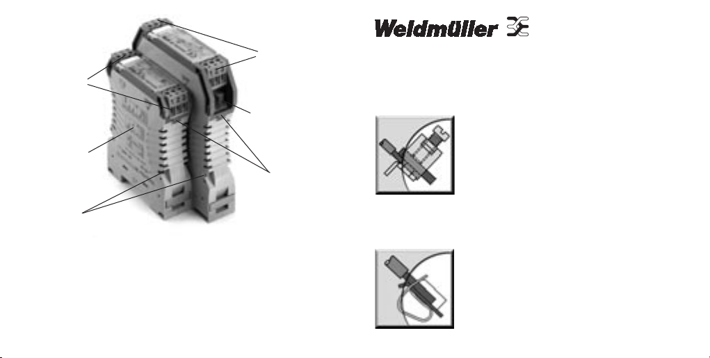
3. Mounting and Settings
3.1 Range adjustments
1. Remove connector
2. Press locking clips on both sides of the enclosure and pull out the
circuit board
3. Make required adjustments to the input range, hysteresis, frequency
and relay control using the DIP switches (by print to the side of the
enclosure ).
4. Replace connector after making adjustments
The connectors have been coded by the manufacturer, ensuring that
they cannot be reversed .
5. If using the feed-through version, push through enclosing wire
Warning!!
The circuit board can only be inserted in one position.
3.2 Cross-connections for voltage supply
A maximum feed through of 2 A is possible
The cross-connectors have been coded by the manufacturer, preventing a
short circuit should the cross-connectors be reversed
Page 4

1514
3.3 Modules with relay output
SW3=OFF: hysteresis approx. 5% of the set value
SW3=ON: hysteresis app. 10% of the set value
SW4=OFF: relay switches when input > threshold value
SW4=ON: relay switches when input < threshold value
Signal Range SW1 SW2 SW3 SW4
Input 1 Aac OFF ON
5 Aac ON OFF
10 Aac OFF OFF
Signal Range SW1 SW2 SW3 SW4
Input 20 Aac OFF OFF
40 Aac ON OFF
60 Aac ON ON
3.4 Modules with analog outputs
Signal Range SW1 SW2 SW3 SW4 SW5
Input 20/40 Auc OFF OFF
5/25/50 Auc OFF ON
10/30/60 Auc ON OFF
AC Current ON
DC Current OFF
Output 0...10 V ON OFF
0...20 mA OFF OFF
4...20 mA OFF ON
Best.-Nr.
8516560000
8516570000
Best.-Nr.
8513340000
8526600000
Best.-Nr.
8513330000
8526590000
8526610000
8526620000
8545830000
8545840000
Cat. No.
8516560000
8516570000
Cat. No.
8513340000
8526600000
Cat. No.
8513330000
8526590000
8526610000
8526620000
8545830000
8545840000
Signal Range SW1 SW2 SW3 SW4 SW5 SW6 SW7 SW8
Input 1 Aac OFF OFF ON
5 Aac OFF ON OFF
10 Aac ON OFF OFF
Output 0...10 V ON OFF ON ON OFF
0...20 mA OFF OFF OFF OFF ON
4...20 mA OFF ON OFF OFF ON
Signal Range SW1 SW2 SW3 SW4
Input 1 Aac OFF OFF ON
5 Aac OFF ON OFF
10 Aac ON OFF OFF
Frequenz 50 Hz OFF
60 Hz ON
Signal Range SW1 SW2 SW3 SW4 SW5
Input 5 Aac OFF ON
10 Aac ON OFF
AC Current ON
DC Current OFF
Output 0...10 V ON OFF
0...20 mA OFF OFF
4...20 mA OFF ON
Cat. No.
8523400000
8523410000
Cat. No.
8528650000
8528660000
Cat. No.
8526610000
8526620000
Page 5

17
16
5. Design Variations and Ordering Information
All components are available with pluggable screw (WAS) or tension clamp
connection (WAZ).
Input Output
1/5/10 A ac, selectable 0(4)...20 mA/0...10 V
1/5/10 A ac, selectable 4...20 mA, loop powered
1/5/10 A ac, selectable 1 relay, changeover contact
20/40/60 A ac, selectable 1 relay, changeover contact
5/10 A ac/dc, selectable (TRMS) 0(4)...20 mA / 0...10 V
40/50/60 A ac/dc, selectable (TRMS) 0(4)...20 mA / 0...10 V
20/25/30 A ac/dc, selectable (TRMS) 0(4)...20 mA / 0...10 V
Type Input Output Cat. No. Enclosure
WAS2 CMR 1/5/10 A ac Relay 8516560000 WAVEBOX L 22,5
WAZ2 CMR 1/5/10 A ac Relay 8516570000 WAVEBOX L 22,5
WAS1 CMA 1/5/10 A ac Analog 8523400000 WAVEBOX S 22,5
WAZ1 CMA 1/5/10 A ac Analog 8523410000 WAVEBOX S 22,5
WAS1 CMA LP 1/5/10 A ac Analog 8528650000 WAVEBOX S 22,5
WAZ1 CMA LP 1/5/10 A ac Analog 8528660000 WAVEBOX S 22,5
WAS2 CMA 5/10 A ac/de Analog 8526610000 WAVEBOX L 22,5
WAZ2 CMA 5/10 A ac/de Analog 8526620000 WAVEBOX L 22,5
WAS2 CMR 20/40/60 A ac Relay 8513340000 WAVEBOX L 22,5
WAZ2 CMR 20/40/60 A ac Relay 8526600000 WAVEBOX L 22,5
WAS2 CMA 40/50/60 A ac/dc Analog 8513330000 WAVEBOX L 22,5
WAZ2 CMA 40/50/60 A ac/dc Analog 8526590000 WAVEBOX L 22,5
WAS2 CMA 20/25/30 A ac/dc Analog 8545830000 WAVEBOX L 22,5
WAZ2 CMA 20/25/30 A ac/dc Analog 8545840000 WAVEBOX L 22,5
4. Electrical Connection
Pin CMA CMA CMR CMR CMA LP
1/5/10 Aac 40/50/60 Auc 1/5/10 Aac 20/40/60 Aac 1/5/10 Aac
20/25/30 Auc
1/5/10 Aac 20/40/60 Aac 1/5/10 Aac
5/10 Auc
1 NC 24 Vdc 24 Vdc 24 Vdc NC
2 Input 0 V 0 V 0 V Input
3 Input 0 V 0 V 0 V Input
4NC
5 Input
6 Input
7 24 Vdc 0...10 V Contact 11 Out+
8 Output 0(4)...20 mA Contact 12 NC
9 0 V 0 V Contact 14 Out10 Contact 11
11 Contact 14
12 Contact 12
l.d.c. Input* Input*
connection
*) Diameter of grommet: 8 mm
NC = no connection
Page 6

1918
7. CE Labeling of WAVECONTROL Modules
WAVECONTROL modules carry the CE Mark and comply with the requirements of the EU guidelines 89/336/EWG “Electromagnetic Compatibility”
and the therein listed harmonized European Norms (EN).
The EU declarations of conformity are held for the relevant authorities, in
accordance with Article 10 of the above mentioned EU guideline, at the
following address :
Weidmüller Interface GmbH & Co.
Postfach 30 30
32720 Detmold
Tel. +49 5231 14-0
Fax +49 5231 14-2083
e-mail: info@weidmueller.com
www.weidmueller.com
6. Accessories
Cat. No.
Cross-connection ZQV 2,5N/2 black 1718080000
Cross-connection ZQV 2,5N/2 red 1717900000
Cross-connection ZQV 2,5N/2 blue 1717990000
Cross-connection ZQV 2,5N/2 yellow 1693800000
Terminal connector, 3-pole
for screw-type connection BLZ 5.08/3 SN OR
– orange 1526560000
– black 1526510000
Terminal connector, 3-pole
for tension clamp connection BLZF 5.08/3
– orange 1707470000
– black 1707700000
Connector markers
– WS 10/5 Multicard for plotter labelling 1635010000
– WS 10/5 blank 1060860000
 Loading...