

Page 1
Beipackinformation 1
Operating Instructions15
Notice d’utilisation 27
Analogsignaltrenner
WAVE
ANALOG PRO Thermo
aus der WAVESERIES
RT Nr. 406043
Page 2

15
Analogue Signal Isolators
WAVESERIES
WAVE
ANALOGUE PRO RTD
MODEL Order Number
Screw terminal connection
WAS5 PRO Thermo 8560720000
Tension clamp connection
WAZ5 PRO Thermo 8560730000
Please read these instructions before using the product
and retain for future information.
Page 3

16
1. General instructions
Achtung! The analogue signal isolators of the WAVE
ANALOGUE PRO series
may only be installed by qualified personnel. Be sure not to connect the unit to power supply before appropriate installation. Do
not select ranges during operation, because live parts are exposed during this process. Only use a screwdriver which is properly insulated against the voltage applied to the input when fine
adjusting the potentiometers on the front.
Be sure to observe the national regulations for installation and
selection of cables.
Appropriate safety measures against electrostatic discharge
(ESD) should be taken during assembly and adjustment work on
the WAVE
ANALOGUE PRO.
2. Application
Analouge singnal isolators are used for galvanic isolation and conversion of
thermoelement signals. Input and output signals are factory set according
to type or can be calibrated/switched via DIP switches. It is not necessary
to adjust the measurement range. A +/- 5% variation can be achieved in
the respective range by connecting potentiometers for zero and span. The
transmitted measurement signal is linear to be measured temperature.
Page 4
17
3. Configuration
3.1 Equipment
A screwdriver with a width of 2.5 mm is required to adjust the unit and to
connect the wires to the terminals.
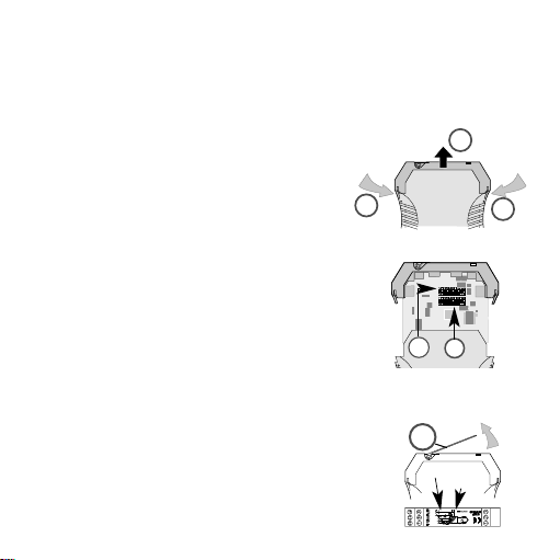
3.2 Opening the unit
Disconnect the plugs. Disengage the top part of
the housing by carefully pressing the latches on
both sides (1). Pull out the top part of the housing and the electronics section until they lock
(2).
3.3 Settings
Set input and output ranges, minimum input values
and measuring span via the DIP switches SW1 and
SW2 according to the following tables.
When activating variable setting SW 1/8 of the span
or offset, it is possible to make additional adjustments via front potentiometers span and offset, accessible below cover (3).
Caution! Only use a screwdriver which is properly
insulated against the voltage applied to
the input when fine adjusting the potentiometers on the front.
1
1
2
Zero
Span
SW2
SW1
3
Page 5

18
Selecting the thermoelement
SW1
Type 1 2 3
K 111
J 011
T 101
E 001
N 110
R 010
S 100
B 000
Selecting the minimum temperature
SW1
min 4567
0º C 1111
–10º C 1110
–20º C 1101
–30º C 1100
–40º C 1011
–50º C 1010
–100º C 1001
–150º C 1000
–200º C 0111
+50º C 0110
+100º C 0101
Page 6

19
SW1
min 4567
+150º C 0100
+200º C 0011
+250º C 0010
+500º C 0001
Special range 0000
Activating the manual fine adjustment
SW1
manual calibration 8
off 0
on 1
1 = on
0 = off
Page 7

20
Selecting the temperature span
SW2
Span 12345
100º C 11111
150º C 11110
200º C 11101
250º C 11100
300º C 11011
350º C 11010
400º C 11001
450º C 11000
500º C 10111
550º C 10110
600º C 10101
650º C 10100
700º C 10011
750º C 10010
800º C 10001
850º C 10000
900º C 01111
950º C 01110
1000º C 01101
1050º C 01100
1100º C 01011
1150º C 01010
1200º C 01001
1250º C 01000
Page 8

21
SW2
Span 12345
1300º C 00111
1350º C 00110
1400º C 00101
1450º C 00100
1500º C 00011
1600º C 00010
1700º C 00001
1800º C 00000
Selecting the output
SW2
Output 6 7
0…10 V 1 0
0…20 mA 0 0
4…20 mA 0 1
Activating the filter function
SW2
Filter 8
off 0
on 1
1 = on
0 = off
Page 9

Should a temperature measurement range be selected that is larger than
the specified range of the thermoelement used, then the module sets itself
to the maximum specified range:
Type K –200º C … +1372º C
Type J –200º C … +1200º C
Type T –200º C … +400º C
Type E –200º C … +1000º C
Type N –200º C … +1300º C
Type R –50º C … +1760º C
Type S –50º C … +1760º C
Type B +50º C … +1820º C
The voltage output and the combined current output (0…20 mA and
4…20 mA) are routed from two separate, calibrated connections.
The output selected via the DIP switch, is the only output that is calibrated.
Page 10

23
4. Mounting
Die The analogue signal isolators are mounted on standard TS 35 rails.
5. Electrical connection
Warning! For applications with high isolation voltages, take measures to
prevent accidental contact and make sure that there is sufficient distance or insulation between adjacent devices!
5.1 Power supply
approx. 1 W
18…30 Vdc
Voltage supply via cross-connections. Operating carrying capacity of crossconnection 2 A (see Cat. No. point 7)
Klemmenbelegung
1 Eingang + > 5 mA
2 Eingang + ≤ 500 mV / ≤ 5 mA
3 Eingang + > 500 mV
4 Eingang -
5 Ausgang +
6 Ausgang -
7 Versorgungsspannung
8 Versorgungsspannung
Anschlu§querschnitt max. 2,5 mm
2
Mehrleiteranschlu§ max. 1 mm
2
(zwei Leiter gleichen Querschnitts)
78
10
1
2
3
9
11
12
WAS5 PRO Thermo
7
8
24V
Th1
3Th
nc2
I
0/4...20mA
0...10V
V
8560720000
9
0V
10
11
12
cc
nc
W
e dm ü
lleri
0V.
q
V/IV/I
PSPS
06 06
cccc
Terminal assignments
1 Thermo +
2 not assigned
3 Thermo –
7 Output + 0/4…20 mA
8 Output + 0…10 V
9 Output 0 V
10 Power supply + 24 Vdc (cross connected)
11 Power supply GND (cross connected)
12 not assigned
Wire cross-section max. 2.5 mm
2
Multi-wire conncection max. 1 mm
2
(two wires with same cross-section)
Page 11

24
92.4
90
38
111.4
73.4
17.5
mm
Cross-connections
for power supply
GND
24 Vdc
6. Dimensions
Page 12

25
7. Accessories (cross-connection)
Designation Cat. No.
ZQV 2,5 N/2 yellow 169380
ZQV 2,5 N/2 red 171790
ZQV 2,5 N/2 blue 171799
ZQV 2,5 N/2 black 171808
Connection markers
Designation Cat. No.
WS 10/5 Multicard for plotter marking 163501
WS 10/5 Neutral 106086
8. Notes on CE marking
The WAS5/WAZ5 DC/DC analog signal isolators are marked CE in
accordance with the EU directives 89/336/EEC "Electromagnetic
Compatibility" and 73/23/EEC (low-voltage directive) detailing the
Harmonized European Standards (EN).
The declarations of conformity are held, according the above mentioned
EU directive, article 10, for the authorizing body by:
Weidmüller Interface GmbH & Co.
Postfach 30 30
D-32720 Detmold
Tel. (05231) 14-0
Fax (05231) 14-2083
Page 13

26
Weidmüller Interface GmbH & Co.
Postfach 30 30
D-32720 Detmold
Tel. (0 52 31) 14-0
Fax (0 52 31) 14-2083
 Loading...