

Weidmuller UR67-MP-HP-16DI-12-60M, UR67-MP-78-16DO-12-60M, UR67-MP-78-8DIDO-12-60M, UR67-MP-HP-8DIDO-12-60M, UR67-MP-78-16DI-12-60M Series Manual
...Page 1

Remote-I/O-System u-remote UR67
I/O-Modules IP67 Multiprotocol
Manual
Letʼs connect.
UR67-MP-HP-16DI-12-60M 2426270000
UR67-MP-HP-16DO-12-60M 2426280000
UR67-MP-HP-8DIDO-12-60M 2426290000
UR67-MP-78-16DI-12-60M 2426300000
UR67-MP-78-16DO-12-60M 2426310000
UR67-MP-78-8DIDO-12-60M 2426320000
Page 2

Content
1 About this documentation 3
1.1 Symbols and notes 3
1.2 Complete documentation 3
1.3 Standard data structure 3
2 Safety 4
2.1 General safety notice 4
2.2 Intended use 4
2.3 Legal notice 5
3 System overview 6
3.1 Connection characteristics 6
3.2 Fieldbus characteristics 6
3.3 Web server 7
3.4 Accessories 7
4 Module descriptions 8
4.1 UR67-MP-HP-16DI-12-60M and
UR67-MP-78-16DI-12-60M 8
4.2 UR67-MP-HP-16DO-12-60M and
UR67-MP-78-16DO-12-60M 9
4.3 UR67-MP-HP-8DIDO-12-60M and
UR67-MP-78-8DIDO-12-60M 10
4.4 Connector pin assignment 11
4.5 Technical Data 12
5 Installation and wiring 14
5.1 Preparations for installation 14
5.2 Installing the module and earth connection 14
5.3 Attaching markers 17
5.4 Setting the eldbus protocol 17
5.5 Wiring 17
5.6 Insulation test 17
7 Commissioning 23
7.1 Setting the eldbus protocol 23
7.2 Restoring factory settings using the rotary switch 23
7.3 Commissioning with Ethernet/IP 24
7.4 Commissioning with PROFINET 28
7.5 Parameter settings 32
8 Process data 33
8.1 Process data with Ethernet/IP 33
8.2 Process data with PROFINET 34
9 Diagnostics 35
9.1 Descriptions of errors 35
9.2 Ethernet/IP diagnoses 36
9.3 PROFINET diagnoses 36
10 Web server 37
10.1 Connecting and starting up the web server 37
10.2 Getting to know and arranging the web server 37
10.3 Module settings and diagnostics 39
10.4 Web server in Force mode 41
10.5 Updating rmware 42
11 Disassembly and disposal 43
11.1 Disassembling the u-remote module 43
11.2 Disposing of the u-remote module 43
12 LED displays 44
6 Earthing and shielding 18
6.1 Earthing of shielded cables 18
6.2 Potential ratios 20
6.3 Electromagnetic compatibility (EMC) 20
6.4 Shielding of cables 21
Manufacturer
Weidmüller Interface GmbH & Co. KG
Klingenbergstraße 16
D-32758 Detmold
T +49 5231 14-0
F +49 5231 14-292083
info@weidmueller.com
www.weidmueller.com
Document No. 2484940000
Revision 00/February 2017
22484940000/00/02.2017 Manual UR67-Multiprotocol
Page 3
1 About this documentation
1 About this documentation | Symbols and notes
1.1 Symbols and notes
The safety notices in this documentation are designed according to the severity of the danger.
DANGER
Imminent danger to life!
Notes with the signal word “Danger” warn
you of situations that will result in serious
injury or death if you do not follow the
instructions given in this manual.
WARNING
Possible danger to life!
Notes with the signal word “Warning” warn
you of situations that may result in serious
injury or death if you do not follow the
instructions given in this manual.
CAUTION
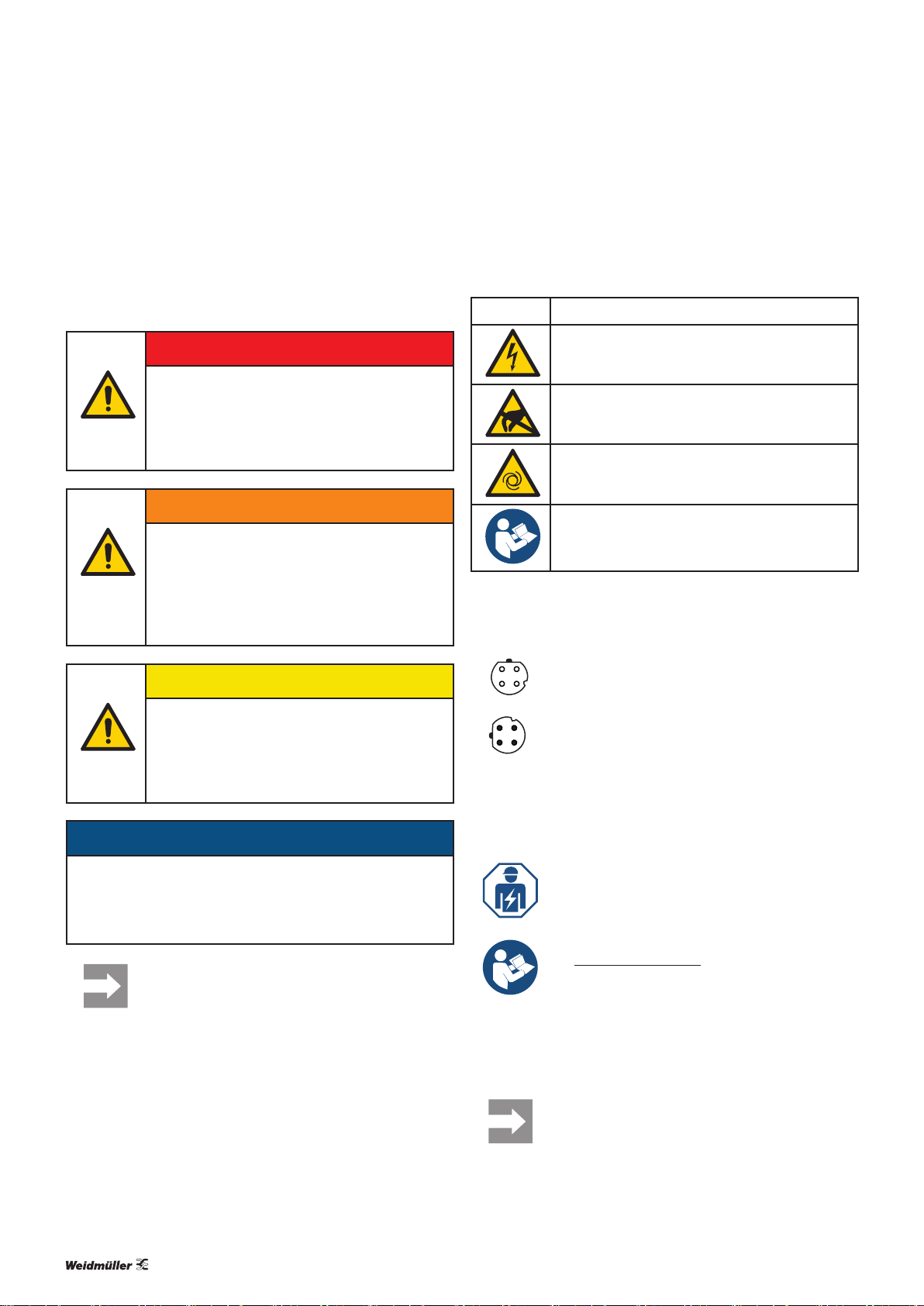
The situation-dependent safety notices may contain the following warning symbols:
Symbol Meaning
Warning against dangerous electrical voltage
Warning against electrostatically charged
components
Warning against automatic startup
Observe the documentation
▶ All instructions can be identified by the black triangles
next to the text.
– Lists are marked with a tick.
21
Female connections with sockets are illustrated
4
using empty circles.
3
Risk of injury!
Notes with the signal word “Caution” warn
you of situations that may result in injury if
you do not follow the instructions given in
this manual.
ATTENTION
Material damage!
Notes with the signal word “Attention” warn you of hazards
that may result in material damage.
Text next to this arrow are notes that are not
relevant to safety, but provide important information about proper and effective work procedures.
Male connections with pins are illustrated using
34
1
lled circles.
2
1.2 Complete documentation
The documentation is intended for trained electricians who are familiar with national and international laws, provisions and standards.
All documents can also be downloaded from
the Weidmüller website.
1.3 Standard data structure
All information about the structure of data
(e.g.process data and parameters) refers to the
standard data format settings in the module
parameters. These are shown in the Motorola
format.
32484940000/00/02.2017 Manual UR67-Multiprotocol
Page 4

2 Safety
2 Safety | General safety notice
This chapter includes general safety instructions on handling
the UR67 modules. Specic safety instructions for specic
tasks and situations are given at the appropriate places in
the documentation.
All work may only be carried out by trained
electricians who are familiar with the
safety standards that apply to automation
technology.
The documentation must be stored in such a
way that it is accessible to operating staff at
all times.
2.1 General safety notice
When working during ongoing operations, the emergency
stop mechanisms must not be made ineffective.
If faults connected to a u-remote product cannot be rectied,
the product in question must be sent to Weidmüller. Weidmüller assumes no liability if the module is tampered with!
All connected devices must comply with the requirements
set out in EN61558-2-4 and EN61558-2-6. Only cables
and accessories that meet the requirements and provisions
regarding safety, electromagnetic compatibility and, if necessary, telecommunications terminal equipment, as well as the
specications, may be installed. Information on the specic
cables and accessories that are permitted to be installed is
provided in this manual or can be requested from Weidmüller.
Electrostatic Discharge
u-remote products can be damaged or destroyed by electrostatic discharge. When handling the products, the neces-
sary safety measures against electrostatic discharge (ESD)
according to IEC61340-5-1 and IEC61340-5-2 must be
observed. The packing and unpacking as well as the installation and disassembly of a device may only be carried out by
qualied personnel.
Fusing
The operator must set up the equipment so that it is protected against overloading. The upstream fuse must be
designed so that it does not exceed the maximum load current. The maximum permissible load current can be found
in the technical data. The operator must decide whether ad-
ditional surge protection is required according to IEC62305.
Voltages that exceed +/-30V may cause the destruction of
the modules. A power supply with secure isolation must be
used.
Earthing (functional earth FE)
Every UR67-MP module is equipped with an earth connection, with the connection point labelled “XE”. Further information is available in chapters 5 and 6.
Shielding
Shielded lines are to be connected with shielded plugs in
compliance with the relevant standard (see chapter 6).
2.2 Intended use
The UR67-MP modules are decentral input and output devices in an Ethernet/IP network or a PROFINET network.
The products are designed for use in industrial automation and may only be used within the scope of the stated
technical specications. The devices to be connected must
comply with the requirements set out in EN61558-2-4 and
EN61558-2-6.
The industrial environment is labelled as such to ensure that
consumers are not directly connected to the public low-voltage network. Additional measures must be taken for use in
the home, and in the business and commercial sectors.
Any intervention in the products hardware or software other
than described in this manual may only be realised by Weidmüller.
Malfunction-free operation is only guaranteed if the housing
is fully assembled. Observance of the documentation is also
part of the intended use.
42484940000/00/02.2017 Manual UR67-Multiprotocol
Page 5

2.3 Legal notice
The UR67-series products comply with the EU Directive
2014/30/EU (EMC Directive).
Components of the following free software products are integrated into the modules:
Component License Link
jQuery MIT
jQuery-custom-
Select
jQuery-i18n MIT
jQuery-overs-
croll
jQuery-ui MIT
JSZip MIT
md5 (as part
of CryptoJS)
snap-svg
underscore MIT
MIT
MIT
MIT
Apache
license 2.0
https://github.com/jquery/jquery/blob/master/
LICENSE.txt
https://github.com/jquery/jquery/blob/master/
LICENSE.txt
https://github.com/jquery/jquery/blob/master/
LICENSE.txt
https://github.com/jquery/jquery/blob/master/
LICENSE.txt
https://github.com/jquery/jquery/blob/master/
LICENSE.txt
https://github.com/Stuk/jszip/blob/master/
LICENSE.markdown
https://code.google.com/archive/p/crypto-js/
wikis/License.wiki
https://github.com/adobe-webplatform/Snap.
svg/blob/master/LICENSE
https://github.com/jashkenas/underscore/blob/
master/LICENSE
2 Safety | Legal notice
52484940000/00/02.2017 Manual UR67-Multiprotocol
Page 6

3 System overview | Connection characteristics
3 System overview
UR67-MP-HP-X (2426270000, 2426280000, 2426290000) UR67-MP-78-X (2426300000, 2426310000, 2426320000)
u-remote IP67 modules for Ethernet/IP and PROFINET
The UR67-MP modules are multi-protocol modules which
use either Ethernet/IP or PROFINET for eldbus communication. The required protocol is selected on the module using
the rotary switch.
The metal housing (zinc diecast, completely encapsulated)
ensures that the modules conform to the IP67 protection
class.
The output current is a maximum of 1.6 A per channel. The
output circuits are electrically isolated from the rest of the
network and from the sensor electronics.
The modules with output functionality support a fail-safe
function, which can be used to set how a channel congured
as an output is to respond to an impaired or interrupted eld-
bus communication.
The UR67-MP modules differ according to their I/O functionality:
– 16 digital inputs (UR67-MP-xx-16DI-12-60M)
– 16 digital outputs (UR67-MP-xx-16DO-12-60M)
– 8 digital inputs and 8 digital outputs (UR67-MP-xx-
8DIDO-12-60M).
The UR67-MP modules feature two different connections for
the power supply:
3.1 Connection characteristics
All connections are colour-coded and therefore cannot be
mixed up:
– Fieldbus network (green): D-coded, 4-pole M12 plug-in
connector (IN and OUT). The maximum transmission rate
is 100Mbps.
– I/O connections (black): 8 A-coded, 5-pole M12 plug-in
connectors
– Power supply connections (grey), variant-specific:
– L-coded, 5-pole M12 connector (IN and OUT).
– 5-pole, 7/8“-connections (IN and OUT)
LED
Each I/O connection is assigned two status LEDs which
change colour and the frequency at which they ash according to the status of the respective connection (seesec-
tion12).
3.2 Fieldbus characteristics
– 5-pole, L-coded M12 connections (UR67-MP-HP-xx)
– 5-pole, 7/8“-connections (UR67-MP-78-xx)
The integrated Ethernet switch with two connections allows
for Ethernet/IP and PROFINET networks to be set up in a line
or ring topology.
Ethernet/IP product characteristics
The rmware for the UR67-MP modules supports the Device Level Ring protocol (DLR) for simple ring topologies in
accordance with the Ethernet/IP specication. DLR allows
modules to switch to an alternative ring segment in the event
of an interruption to the connection. The DLR class of the
modules is “Ring Node, Beacon Based”.
62484940000/00/02.2017 Manual UR67-Multiprotocol
Page 7
3 System overview | Web server
PROFINET product characteristics
The UR67-MP modules support PROFINET IO device IRT
(Isochronous Real-Time). This allows time-critical process
data to be transmitted between the network components in
real time.
The UR67-MP modules use the following protocols:
– DCP: for the automatic allocation of IP addresses
– LLDP: for device detection in the immediate surround-
ings (neighbourhood detection)
– SNMP: for monitoring network components
The UR67-MP modules support the “Device replacement
without interchangeable medium” function. With this function, modules in a PROFINET network can be exchanged
for identical modules without having to reassign the device
name using a programming device.
Alarm and diagnostic messages
The modules offer extended Ethernet/IP and PROFINET
alarm and diagnostic messages.
Conguration and parameterisation
An EDS le (Ethernet/IP) or a GSDML le (PROFINET) is
needed to congure and parameterise the module in the en-
gineering tool.
The current EDS and GSDML les can be downloaded from the Weidmüller website.
3.4 Accessories
Protective caps
Protection class IP67 is only realised with a completely connected module. This means that all of the connections not
being used must be provided with protective caps.
Size Usage Protective cap Order No.
M12 Sensor connection SAI-SK M12 9456050000
M12 Bus-out and power-out SAI-SK-M12-UNI 2330260000
M12 Bus-in and power-in SAI-SK M12 connector 1781520000
7/8“ Power-Out SAI-7/8-SK-P-F 1422760000
7/8“ Power-In SAI-7/8-SK-P-M 2007270000
Markers
Module and connection markers are available to label equipment. All of the markers can be printed using the Weidmüller
PrintJet ADVANCED (Order No. 1324380000).
Module Markers Order No.
UR67-MP-xx-xxx-60M ESG-M8/20 MC NE WS 1027290000
Conductors and connections
In order to select suitable cables, we recommend referring to
Weidmüller Catalogue 8 or the Product Congurator on the
Weidmüller-Website.
3.3 Web server
The web server can be used to display the UR67-MP module
on a connected PC. This allows you to execute the following
functions for test purposes or during commissioning or service work:
– Query the module status
– Display and change the module parameters
– Access diagnostic information
– Operate the module in Force mode for testing purposes
The description of the web server can be found in chap-
ter10.
72484940000/00/02.2017 Manual UR67-Multiprotocol
Page 8
IN OUT
X01
UR67-MP-78-16DI-12-60M
IN
4
8
3 7
6
5
2
A
DIA
B
XE
OUT
Lnk/Act
P2P1
U
S
16DI
A
DIA
B
A
DIA
B
A
DIA
B
x100
x10
x1
MS NS
BF DIA
0
E/IP
PN
0
0
BUS
1
12
11
10
2
1
7
6
5
4
3
9
8
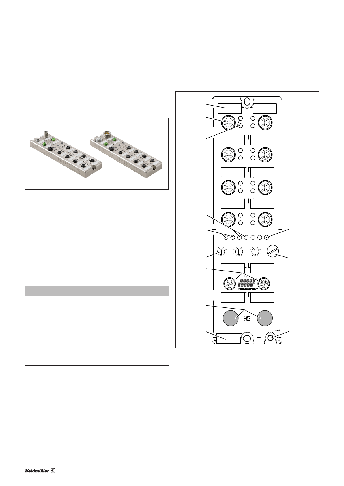
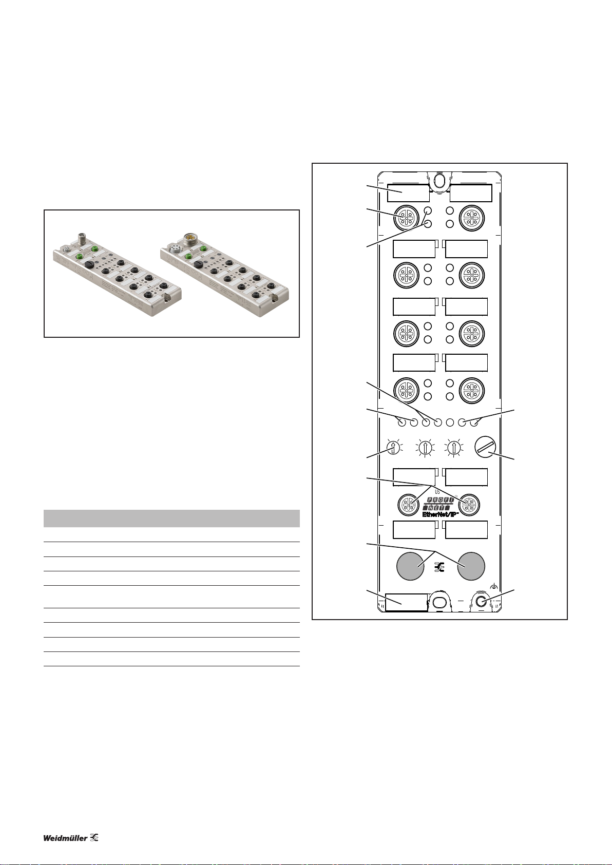
4 Module descriptions
4.1 UR67-MP-HP-16DI-12-60M and
UR67-MP-78-16DI-12-60M
4 Module descriptions | UR67-MP-HP-16DI-12-60M and UR67-MP-78-16DI-12-60M
Left: Input module UR67-MP-HP-16DI-12-60M (Order No. 2426270000)
Right: Input module UR67-MP-78-16DI-12-60M (Order No. 2426300000)
The UR67-MP modules are intended for the decentralised
control in an Ethernet/IP network or a PROFINET network.
The protocol is selected using the rotary switch.
Each module has eight connections (M12, 5-pole, A-coded)
for signal lines as well as connections for the eldbus (M12,
4-pole, D-coded). The power supply is connected via 5-pole,
A-coded M12 or 7/8" connections.
The UR67-MP-xx-16DI-12-60M modules have 16digital inputs (P-switching).
Diagnostic and status LEDs
LED Display Meaning
U
S
1–8 A Yellow Channel A status: On
1 –8 B White Channel B status: On
Lnk/Act
P1, P2
BF/MS Green Device operational (Ethernet/IP)
BF/MS Off No error (PROFINET)
DIA/NS Green Connected: at least one existing connection (Ethernet/IP)
DIA/NS Off No diagnosis available (PROFINET)
LED displays (normal operation); for error messages, see chapter 12
detected
Green System/sensor power supply
Green Ethernet connection to another participant available, link
Product details for UR67-MP-HP-16DI-12-60M and UR67-MP-78-16DI-12-60M
1 Marker connection1
2 I/O connections1 (sensor/actuator)
3 Status LED connection1, channelA/channelB
4 Fieldbus and module status LEDs
5 Lnk/Act status LEDs
6 Rotary switch (for setting the protocol)
7 Fieldbus connection
8 M12 or 7/8" power supply connection
9 Module marker
10 Power supply status LED (U
system/sensor power supply)
S
11 Micro-USB port (not to be used by the customer)
12 Earth connection (M4 thread)
82484940000/00/02.2017 Manual UR67-Multiprotocol
Page 9
4.2 UR67-MP-HP-16DO-12-60M and
IN OUT
X01
UR67-MP-78-16DO-12-60M
IN
4
8
3 7
6
5
2
A
DIA
B
XE
OUT
Lnk/Act
P2P1
USU
L
16DO
A
DIA
B
A
DIA
B
A
DIA
B
x100
x10
x1
MS NS
BF DIA
0
E/IP
PN
0
0
BUS
1
12
11
10
2
1
7
6
5
4
3
9
8
UR67-MP-78-16DO-12-60M
4 Module descriptions | UR67-MP-HP-16DO-12-60M and UR67-MP-78-16DO-12-60M
Left: Output module UR67-MP-HP-16DO-12-60M (Order No. 2426280000)
Right: Output module UR67-MP-78-16DO-12-60M (Order No. 2426310000)
The UR67-MP modules are intended for the decentralised
control in an Ethernet/IP network or a PROFINET network.
The protocol is selected using the rotary switch.
Each module has eight connections (M12, 5-pole, A-coded)
for signal lines as well as connections for the eldbus (M12,
4-pole, D-coded). The power supply is connected via 5-pole,
A-coded M12 or 7/8" connections.
The UR67-MP-xx-16DO-12-60M modules have 16 digital
outputs (P-switching).
Diagnostic and status LEDs
LED Display Meaning
U
L
U
S
1–8 A Yellow Channel A status: On
1 –8 B White Channel B status: On
Lnk/Act
P1, P2
BF/MS Green Device operational (Ethernet/IP)
BF/MS Off No error (PROFINET)
DIA/NS Green Connected: at least one existing connection (Ethernet/IP)
DIA/NS Off No diagnosis available (PROFINET)
LED displays (normal operation); for error messages, see chapter 12
Green Actuator power supply
Green System/sensor power supply
Green Ethernet connection to another participant available, link
detected
Product details for UR67-MP-HP-16DO-12-60M and UR67-MP-78-16DO-12-60M
1 Marker connection1
2 I/O connections1 (sensor/actuator)
3 Status LED connection1, channelA/channelB
4 Fieldbus and module status LEDs
5 Lnk/Act status LEDs
6 Rotary switch (for setting the protocol)
7 Fieldbus connection
8 M12 or 7/8" power supply connection
9 Module marker
10 Power supply status LED (U
actuator power supply, US system/sensor
L
power supply)
11 Micro-USB port (not to be used by the customer)
12 Earth connection (M4 thread)
92484940000/00/02.2017 Manual UR67-Multiprotocol
Page 10

4.3 UR67-MP-HP-8DIDO-12-60M and
IN OUT
X01
UR67-MP-78-8DIDO-12-60M
IN
4
8
3 7
6
5
2
A
DIA
B
XE
OUT
Lnk/Act
P2P1
USU
L
8DIDO
A
DIA
B
A
DIA
B
A
DIA
B
x100
x10
x1
MS NS
BF DIA
0
E/IP
PN
0
0
BUS
1
12
11
2
1
7
6
5
4
3
9
8
10
UR67-MP-78-8DIDO-12-60M
4 Module descriptions | UR67-MP-HP-8DIDO-12-60M and UR67-MP-78-8DIDO-12-60M
Left: Input/Output module UR67-MP-HP-8DIDO-12-60M (Order No. 2426290000)
Right: Input/Output module UR67-MP-78-8DIDO-12-60M (Order No. 2426320000)
The UR67-MP modules are intended for the decentralised
control in an Ethernet/IP network or a PROFINET network.
The protocol is selected using the rotary switch.
Each module has eight connections (M12, 5-pole, A-coded)
for signal lines as well as connections for the eldbus (M12,
4-pole, D-coded). The power supply is connected via 5-pole,
A-coded M12 or 7/8" connections.
The UR67-MP-xx-16DI-12-60M modules have 8digital inputs (P-switching) and 8digital outputs.
Diagnostic and status LEDs
LED Display Meaning
U
L
U
S
1–8 A Yellow Channel A status: On
1 –8 B White Channel B status: On
Lnk/Act
P1, P2
BF/MS Green Device operational (Ethernet/IP)
BF/MS Off No error (PROFINET)
DIA/NS Green Connected: at least one existing connection (Ethernet/IP)
DIA/NS Off No diagnosis available (PROFINET)
LED displays (normal operation); for error messages, see chapter 12
Green Actuator power supply
Green System/sensor power supply
Green Ethernet connection to another participant available, link
detected
Product details for UR67-MP-HP-8DIDO-12-60M and UR67-MP-78-8DIDO-12-60M
1 Marker connection1
2 I/O connections1 (sensor/actuator)
3 Status LED connection1, channelA/channelB
4 Fieldbus and module status LEDs
5 Lnk/Act status LEDs
6 Rotary switch (for setting the protocol)
7 Fieldbus connection
8 M12 or 7/8" power supply connection
9 Module marker
10 Power supply status LED (U
actuator power supply, US system/sensor
L
power supply)
11 Micro-USB port (not to be used by the customer)
12 Earth connection (M4 thread)
102484940000/00/02.2017 Manual UR67-Multiprotocol
Page 11
4 Module descriptions | Connector pin assignment
5
3
3
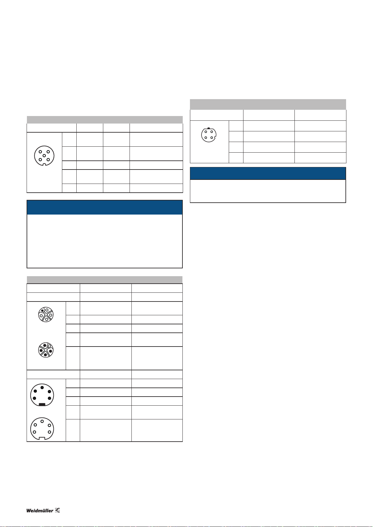
4.4 Connector pin assignment
I/O connections
M12, A-coded 16DI 16DO 8DIDO
1 24V n.c.
3
2
4
2 In B Out B
1
3 GND 0V GND 0V GND 0V
4 In A Out A
5 FE FE FE
ATTENTION
For the system/sensor power supply and the actuator power supply, please only use power supplies that
conform to PELV (Protective Extra Low Voltage) or SELV
(Safety Extra Low Voltage) requirements. Power supplies in accordance with EN61558-2-6 (transformer) or
EN60950-1 (switched-mode power supply) meet these
requirements.
Power supply connection
Plug-in connector Signal Function
M12, 5-pole, L-coded
1
5
4
3
OUT
1
2
3
IN
7/8"
5
2 4
1
1 U
2
2 GND_U
3 GND_U
5
4 UL (+24V)
4
5 FE (PE) Functional earth
1 GND_U
24
2 GND_U
1
3 FE (PE) Functional earth
4 U
5
5 U
(+24V)
S
(+24V)
S
(+24V)
L
L
S
L
S
24V (connections 1–4)
n.c. (connections 5–8)
In B (connections 1–4)
Out B (connections 5–8)
In A (connections 1–4)
Out A (connections 5–8)
System/sensor power
supply
Earth/reference potential U
Earth/reference potential U
Actuator power supply
(electrically isolated)
Earth/reference potential U
Earth/reference potential U
System/sensor power
supply
Actuator power supply
(electrogalvanised)
PROFINET Ethernet/IP
M12, 4-pole, D-coded Signal Function
21
4
3
1 TD+ Transmission data +
2 RD+ Receive data +
3 TD– Transmission data –
4 RD– Receive data –
ATTENTION
The product can be destroyed!
▶ Never place the power supply (24VDC) on the signal
or data lines.
L
S
L
S
112484940000/00/02.2017 Manual UR67-Multiprotocol
Page 12

4.5 Technical Data
4 Module descriptions | Technical Data
Technical data UR67-MP-xx-16DI-12-60M
(2426270000, 242630000)
UR67-MP-xx-16DO-12-60M
(2426280000, 2426310000)
UR67-MP-xx-8DIDO-12-60M
(2426290000, 2426320000)
Bus system
Protocol
Vendor name (for Ethernet/IP)
Product type, number (for Ethernet/IP)
Product type, string (for Ethernet/IP)
Product code (for Ethernet/IP)
VendorID (for PROFINET)
DeviceID (for PROFINET)
EDS file (for Ethernet/IP)
GSDML file (for PROFINET)
Data transmission rate
Transmission method
Auto-negotiation
Switch functionality
Ethernet protocols supported
Connection
34003 (for UR67-MP-HP-16DI-12-60M)
34000 (for UR67-MP-78-16DI-12-60M)
Ping, ARP, DHCP, HTTP, TCP/ IP, BOOTP, beacon-based DLR (Ethernet/IP)
Ping, ARP, LLDP, DCP, HTTP, TCP/ IP, SNMP (PROFINET)
Ethernet/IP, PROFINET
1015
7
General Purpose Discrete I/O
34004 (for UR67-MP-HP-16DO-12-60M)
34001 (for UR67-MP-78-16DO-12-60M)
0x0134 hex
0x18C6 hex
WM_xx_Vz.z-WI-UR67-yyyymmdd.eds
GSDML-Vx.x-WI-UR67-yyyymmdd.xml
10/100 Mbps, Full Duplex (Ethernet/IP)
100 Mbps, Full Duplex (PROFINET)
100BASE-TX
Supported
Integrated, 2 connections
IRT supported (PROFINET)
M12, 4-pole, D-coded
34005 (for UR67-MP-HP-8DIDO-12-60M)
34002 (for UR67-MP-78-8DIDO-12-60M)
Inputs
Number of digital channels
Channel type
Input wiring
Rated input voltage
Input current at 24VDC
Short-circuit-proof
Status indicator
Diagnosis indicator
Connection
Type 3 in acc. with IEC 61131-2 – Type 3 in acc. with IEC 61131-2
Red LED for every M12 socket – Red LED for every M12 socket
16 – 8
NO contact, P-switching – NO contact, P-switching
24VDC – 24VDC
typically 5mA – typically 5mA
Yes – Yes
Yellow LED (channel A)
White LED (channel B)
M12, 5-pole, A-coded – M12, 5-pole, A-coded
– Yellow LED (channel A)
White LED (channel B)
Outputs
Number of digital channels
Channel type
Output wiring
Rated output current per channel
Signal status “1”
Signal status “0”
1)
– 16 8
– NO contact, P-switching NO contact, P-switching
– typically 1.6A in acc. with IEC61131-2 typically 1.6A in acc. with IEC61131-2
– 1.6A 1.6A
– max. 1.6A max. 1.6A
– max. 1mA (specication as per standard) max. 1mA (specication as per standard)
1) In the case of inductive loads in utilisation category DC13 (in acc. withEN60947-5-1), the outputs can operate with currents of 0.5A and a frequency of 1Hz.
2) Technically possible and approved on the following conditions: looped system/sensor power supply – max. 2.5 A; minimum cross-section of power supply wire –
5 x 1.0 mm²; max. ambient temperature – 40°C (104°F)
122484940000/00/02.2017 Manual UR67-Multiprotocol
Page 13

4 Module descriptions | Technical Data
Technical data UR67-MP-xx-16DI-12-60M
(2426270000, 242630000)
Signal level of the outputs
Signal status “1”
Signal status “0”
Short-circuit-proof
Max. current-carrying capacity per mo-
–
– min. (U
– max. 2V max. 2V
– Yes Yes
– 9.0A (12A2)) 9.0A (12A2))
dule
Overload-proof
Status indicator
Diagnosis indicator
Connection
– Yes Yes
– Yellow LED (channel A),
– Red LED, for each channel Red LED, for each channel
– M12 socket, 5-pole, A-coded M12 socket, 5-pole, A-coded
Electronics/sensor power supply
Rated voltage U
S
Voltage range
Electronics current consumption
Sensor voltage
Sensor current consumption
Polarity protection
Status indicator (US)
Connection
Actuator power supply
Rated voltage U
Aux
Voltage range
Potential isolation
Low voltage threshold
Delay time for low voltage detection
Polarity protection
Actuator power supply indicator (U
Connection
)
Aux
– 24 V DC (SELV/PELV)
– 24VDC ± 25%
– Yes
– typically 17 V
– typically 300ms
– Yes
– Green/red LED
– 7/8" plug and socket, 5-pole (UR67-MP-HP-X) M12, 5-pole, L-coded (UR67-MP-78-X)
General data
Type of protection
Ambient temperature
Weight
Enclosure material
Vibration resistance – vibration
Vibration resistance – impact
Tightening torques
M12 plug-in connector
UR67-MP-xx-16DO-12-60M
(2426280000, 2426310000)
– 1V) min. (U
Aux
white LED (channel B)
24 V DC (SELV/PELV)
24VDC ± 25%
typically 60mA
min. (U
max. 200mA (at Tu 30°C)
7/8" plug and socket, 5-pole (UR67-MP-HP-X)
M12, 5-pole, L-coded (UR67-MP-78-X)
IP 67 (only when all ports are either used or sealed)
500g (UR67-MP-HP-X)
520g (UR67-MP-78-X)
Zinc diecast, nickel matt surface nish
– 1.5V)
System
Yes
Green/red LED
-20°C to +70°C
15 g / 5–500 Hz
50 g/11 ms
0.5 Nm
UR67-MP-xx-8DIDO-12-60M
(2426290000, 2426320000)
– 1V)
Aux
Yellow LED (channel A),
white LED (channel B)
1) In the case of inductive loads in utilisation category DC13 (in acc. withEN60947-5-1), the outputs can operate with currents of 0.5A and a frequency of 1Hz.
2) Technically possible and approved on the following conditions: looped system/sensor power supply – max. 2.5 A; minimum cross-section of power supply wire –
5 x 1.0 mm²; max. ambient temperature – 40°C (104°F)
132484940000/00/02.2017 Manual UR67-Multiprotocol
Page 14

5 Installation and wiring
5 Installation and wiring | Preparations for installation
WARNING
Dangerous contact voltage!
▶ All installation and wiring work must be
carried out with the power supply disconnected.
▶ Make sure that the place of installation
has been disconnected from the power
supply!
5.1 Preparations for installation
Make sure that the permitted environmental conditions for
installation and operation are observed (see Technical data).
Installation position and dimensions
The modules must be installed on a level surface. The instal-
lation dimensions and tightening torques for the xings are
provided in the installation drawings on the following pages.
Unpacking the delivery
▶ Please check the delivery for completeness and transport
damage.
▶ Please report any transport damage immediately to the
respective transport company.
5.2 Installing the module and earth connection
▶ Drill the holes for the fixings (for the drilling dimensions,
see the installation drawings on the following pages).
▶ Affix each module with two screws and a washer (as per
DINEN ISO 7089).
▶ Observe the screw dimension and tightening torques indi-
cated.
Element Torque
M12 plug-in connector 0.5Nm
M12 protective cap 0.5Nm
The modules have an earth connection (“XE”) with an M4
thread for discharging interference currents and for EMC
stability.
▶ Connect the earth connection to the reference earth via a
low-impedance connection.
If the mounting surface is earthed, the connection can be
made directly via the mounting screws.
If the mounting surface is not earthed, use an earthing strap
or a suitable cable!
▶ Connect the earthing strap or the FE cable to the earth
connection (“XE”) using an M4 screw.
ATTENTION
The product can be destroyed by electrostatic discharge!
u-remote products can be destroyed by electrostatic discharge.
▶ Please make sure that personnel and work
equipment are adequately earthed!
▶ Unpack the parts.
▶ Dispose of all packaging in accordance with the local dis-
posal guidelines. The cardboard packaging can be sent
for paper recycling.
142484940000/00/02.2017 Manual UR67-Multiprotocol
Page 15

5 Installation and wiring | Installing the module and earth connection
59.6
M12
I/O
M12
BUS
M12
Power
17.6
354
female
12
M12 I/0
Pin
Function
1
24V
In B
2
GND 0V
3
In A
4
5
FE
24V +25% / -25%; 120mA
24V 200mA
-20 ° ... 70 °C / -4 ° ...158 °F
System Power Supply:
Input Power Supply:
Max. Amblent Temp.:
E/IP
0
1
9
2
P
PN
0
1
9
2
8
7
3
4
6
5
0
1
9
2
8
7
3
4
6
5
3 4
female
12
Bus
Pin
Function
1
TD+
2
RD+
3
TD-
4
RD-
Power
FunctionPin
1
+24V
2
GND UL
3
GND 0V
+24V UL
4
FE
5
1
2
5
female
3
4
200.0
29.8
1 5
2
3 7
4
190.0 ... 192.0
Lnk/Act
0
E/IP
x100
IN OUT
IN
PN
P2P1
A
DIA
B
A
DIA
B
A
DIA
B
A
DIA
B
BF DIA
MS NS
0
x10
BUS
M4x25/30
6
8
U
S
0
x1
X01
M4x25/30
OUT
XE
M4
20.030.7
Installation dimensions UR67-MP-HP-16DI-12-60M (2426270000), UR67-MP-HP-16DO-12-60M (2426280000), UR67-MP-HP-8DIDO-12-60M (2426290000)
152484940000/00/02.2017 Manual UR67-Multiprotocol
Page 16

5 Installation and wiring | Installing the module and earth connection
59.6
M12
I/O
M12
BUS
7/8"
Power
17.3
354
female
12
M12 I/0
Pin
Function
1
24V
In B
2
GND 0V
3
In A
4
5
FE
24V +25% / -25%; 120mA
24V 200mA
-20 ° ... +70 °C / -4 ° ... +158 °F
System Power Supply:
Input Power Supply:
Max. Amblent Temp.:
E/IP
0
1
9
2
P
PN
0
1
9
2
8
7
3
4
6
5
0
1
9
2
8
3
7
4
6
5
3 4
female
12
Bus
Pin
Function
1
TD+
2
RD+
3
TD-
4
RD-
Power
FunctionPin
1
GND UL
2
GND 0V
3
FE
4
+24V
5
+24V UL
1
2
3
female
45
206.0
29.8
1
2
3 7
4
0
Lnk/Act
E/IP
197.0 ... 198.0
x100
IN OUT
IN
PN
P2P1
BF DIA
MS NS
0
x10
BUS
A
DIA
B
A
DIA
B
A
DIA
B
A
DIA
B
5
6
8
U
S
0
x1
X01
OUT
M4x25/30
XE
M4
M4x25/30
20.026.2
Installation dimensions UR67-MP-78-16DI-12-60M (2426300000) , UR67-MP-78-16DO-12-60M (2426310000), UR67-MP-78-8DIDO-12-60M (2426320000)
162484940000/00/02.2017 Manual UR67-Multiprotocol
Page 17

5 Installation and wiring | Attaching markers
5.3 Attaching markers
The module and all ports can be labelled using markers. This
ensures clear allocation at all times during maintenance
work.
▶ Press the labelled marker into the corresponding fixture
opening.
▶ To remove a marker, lever it out carefully using a screw-
driver (2.5 or 3mm).
5.4 Setting the eldbus protocol
The eldbus protocol and the IP address of the module can
be adjusted using the rotary switches (see section 7.1).
5.5 Wiring
WARNING
Dangerous contact voltage!
▶ All installation and wiring work must be
carried out with the power supply disconnected.
▶ Make sure that the place of installation
has been disconnected from the power
supply!
5.6 Insulation test
Insulation tests must always be carried out before each commissioning and in accordance with the respective national
provisions.
ATTENTION
The product can be destroyed by too
high test voltage!
Please observe the following during insulation tests:
– The test voltage within a channel must be
between 24V and max. GND of 30V!*
– A test voltage of max. 500 V can be
applied to all other connection points.
* We recommend connecting 24V and GND at the power
supply plug.
Once the module has been mechanically installed, the wiring
can be carried out in accordance with the wiring plan.
Ensure compliance with the minimum permissible cable bending radius.
All unused ports must be sealed with protective caps in order to achieve protection class
IP67.
172484940000/00/02.2017 Manual UR67-Multiprotocol
Page 18

6 Earthing and shielding
6 Earthing and shielding | Earthing of shielded cables
6.1 Earthing of shielded cables
Electrical and electronic systems must be designed such that
they are largely safeguarded against electrical interference,
thus enabling them to operate securely even in the case of
transient interference voltages.
Electrical interference can be introduced into electric circuits
in a variety of ways. The most frequent causes are due to
inductive interference. In addition, galvanic and capacitive
coupling as well as electrical elds and other processes are
causes for interference voltages. Here, high-frequency voltage
uctuations – known as transients – are the cause of interference with a high level of effectiveness.
Shielded cables increase interference resistance
The sources of interference voltages can rarely be eliminated
and even then not always completely. Thus, it is necessary to
take measures to combat their effect. In general, the more effectively interference voltages can be kept away from circuit
elements or can be discharged, the less electrical circuits are
affected. This can be accomplished in a variety of ways with
varying levels of effectiveness. A very effective measure, in
particular for safeguarding against inductive effects, i.e. ensuring “electromagnetic compatibility” (EMC), is the shielding of electrically functional components to earth potential.
In doing so, for instance, components are installed in metallic, earthed housings and the connecting lines are equipped
with shielding.
Proper use of shielded cables
The shielding of cables will only result in the desired effect if
this is implemented properly. Incorrect earthing or the use of
improper components that perform their task inadequately
reduces or even totally eliminates the effect. Placing the
shielding at any spot on the earth potential will not sufce,
as this earth connection may have no effect on high frequencies. In addition, ground loops must also be taken into consideration. Furthermore, the shielding should be earthed over
a large surface area. Beyond that, the quality of the shield
conductor and earthing accessories is also important.
Weidmüller clamping bracket KLBUE 10-20 SC (Order No. 1712321001)
In general, it can be said that interference from cables can
be combated by routing cables as far away as possible from
each other, keeping the common return as short as possible
and using twisted-pair wire. Far better protection, however,
is provided by completely shielding of all cables. This is the
most effective measure that can be taken against the coupling of interference signals.
The best type of shielding consists of a braided mesh sleeve
that uses individual wires made of non-magnetic materials
(copper, aluminium). The braided mesh should be sufciently
large and also be as thick as possible. For cables that are
equipped with foil shields, it is necessary to be aware of the
low mechanical strength and the low current-carrying capacity of the shielding.
In practice, the shield is still often twisted and connected
to a terminal point. There is very high attenuation (voltage
drop) on these connections, especially for high-frequency
interference. Therefore, this type of shielding should not be
used, even for short cable lengths. The shielding of the cable
is practically negated and can, at best, be helpful for lowfrequency interference. We recommend that there is a large
amount of surface contact with the braided shield of the
cable.
There are generally four distinct types of coupling:
– Galvanic coupling
– Capacitive coupling
– Inductive coupling
– Radiation coupling
182484940000/00/02.2017 Manual UR67-Multiprotocol
Page 19

6 Earthing and shielding | Earthing of shielded cables
These types of interference usually occur mixed together, but
they can be categorised as follows:
– Electromagnetic fields
– Ripple voltage (50Hz)
– Lightning
– Interference pulses (current, voltage)
– Transient surge voltages
– Radio interference
– ESD (electrostatic discharge)
– Burst
– Mains feedback
Another area of concern as regards shield
contact is the “ow” within the conductor. Temperature changes caused by the current lead
to changes in the conductor cross-section. A
rigid contact can therefore only be partially
effective. A self-adjusting contact is what is
really required. Weidmüller's clamping bracket
products (KLBÜ series) provide the perfect solution to meet this challenge..
When installing ground connections on shielding, it is generally also important that no earth loops are created. The
smaller the earth loop, the less the danger of the induction
of interference voltages. It is therefore most suitable to have
apurely neutral-point installation.
The following sketches show the possible shielding connections to protective earth.
A one-sided connection of the shielding protects against capacitive coupling of interference voltages.
System 1 System 2
1HF1MM
∬
If you use a two-sided shielding connection, make sure that
compensating current (different earth potentials) does not
ow through the cable shield.
System 1 System 2
Use of a clamping bracket
Effective shielding
It is important that the shielding is not positioned on the
earth of the connected component, but on the protective
earth. In the case of components that are installed in a metal
housing, the shielding must be positioned to this housing. If
no earthed housing is available, the shielding is positioned
on a separate earth.
If you wish to avoid the disadvantages associated with creating an earth loop with two-sided shields, it is recom mended
you connect one side of the shield through ahigh impedance.
System 1 System 2
For longer lengths of shielded cables, such as if a sensor
must be added to a control panel, a potential difference
between both end points must not be ignored.
However, such shield conductors are relatively expensive
and also require more time in working with them. Another
possibility would be to place an additional voltage equalising
cable between the measurement location and the control
panel. The shield can then be hooked up on both sides.
192484940000/00/02.2017 Manual UR67-Multiprotocol
Page 20

6 Earthing and shielding | Potential ratios
A high-impedance earth connection is also another option.
In the control panel, the shield is then connected to the earth
potential, and the shield has a high-impedance connection to
earth at the measurement location via a gas discharge tube.
This solves the problem of a potential transfer and 50-Hz
humming.
For non-isolated measurement locations, two gas discharge
tubes must be installed. One connects the shield to earth,
and the other connects it to the non-isolated measurement
location. This method prevents a galvanic coupling between
the measurement circuit and the earthed measurement
location.
Shield connection
Earth
Measuring point
1 4
5
TS
2 3
IN
OUT
Summary
Earthing is a key element for the reliable functioning of an
electrical system in the event of interference. In this regard,
HF-related aspects must be taken into consideration. Only
the proper use of materials and a well thought-out circuit
design will lead to success.
6.2 Potential ratios
Ensuring EMC
To ensure EMC, the following basic principles must be observed during installation of the u-remote modules:
– Proper, extensive earthing of inactive metal parts
– Correct shielding of cables and equipment
– Proper layout of wires – cabling
– Creation of a uniform reference potential and earthing
ofall electrical equipment
– Special EMC measures for special applications
(e.g. frequency converters, servo drives)
– Contactors and relay coils must be equipped with the
corresponding interference suppressors.
– Devices and function units with higher interferance poten-
tial have to be capsuled if necessary.
Earthing of inactive metal parts
The earthing of all inactive metal parts reduces the inuence
of coupled interference. For this purpose, all inactive metal
parts (such as switch cabinets, cabinet doors, support beams,
mounting plates, DIN rails, etc.) must be con nected to each
other over a large surface area with low impedance, whereby
a uniform reference potential is ensured for all control unit
elements.
Required measures:
– Removal of the insulating layer around screw connec-
tions. Protection of connection points against corrosion
– Connection of moving earthed components (cabinet
doors, separated mounting plates, etc.) through short
earthing straps with large surfaces
– When possible, avoid using aluminium parts, because alu-
minium oxidises easily and in this respect is unsuited for
earthing
The reference potentials of system/input supply and output
supply are galvanically isolated from each other.
6.3 Electromagnetic compatibility (EMC)
u-remote products completely meet EMC requirements. EMC
planning, however, is necessary prior to installation.
Aspects to consider include all potential interference sources
such as galvanic, inductive and capacitive couplings, as well
as radiation couplings.
PE connection
The connection from earth to the PE (protective earth) connection must be done centrally.
WARNING
Possible danger to life!
In the event of a fault, the earth must never
take on a dangerous contact voltage, which is
why it must be connected to a PE conductor.
Unearthed operation
In the event of unearthed operation, the corresponding safety regulations must be observed.
202484940000/00/02.2017 Manual UR67-Multiprotocol
Page 21

6 Earthing and shielding | Shielding of cables
Sensor and actuator lines
To avoid antenna effects caused by looped lines, all lines that
go to a certain sensor or actuator should be combined in one
cable.
Cabinet design according to EMC guideline:
1 Earthing strips
Earthing strips must be used for connecting inactive metal
parts if it is not possible to connect two large pieces of metal. Use short earthing strips with large surfaces.
2 Clamping bracket for signal cables
If shielded signal cables are used, the shield must be at-
tached to the clamping bracket (KLBÜ series) on the busbar
over a large surface. The braided shield must cover and make
good contact with a large part of the clamping bracket.
3 Mounting plate
The support beam for holding control components must be
connected to a large part of the cabinet housing.
4 Busbar
The busbar must be connected via the rail holding xture.
The cable shields are xed to the busbar.
5 Protective earth conductor rail
The protective earth conductor rail must likewise be attached
to a large part of the mounting plate, and it must be connected to the protective earth conductor system via an external cable with a cross-section of at least 10 mm
discharge interference current.
2
, in order to
6 Protective earth terminal strip
The protective earth terminal strip must be connected to the
protective earth conductor rail in a neutral-point conguration.
7 Cable to protective conductor system (earthing
point)
The cable must be connected to a large part of the protective
conductor system.
See also:
EMC Directive 2014/30/EU
24567
3
1
6.4 Shielding of cables
To prevent the coupling of interference voltages and the de-
coupling of interference elds in cables, only shielded cables
made from well-conducting material (copper or aluminium)
with braided shielding and a coverage of at least 80 %
should be used in the design of a cable shield.
212484940000/00/02.2017 Manual UR67-Multiprotocol
Page 22

6 Earthing and shielding | Shielding of cables
Only when a cable shield is connected to the local reference potential on both sides is it possible to achieve optimal
shielding against electric and magnetic elds. Exceptions
are possible, for example, with high-impedance, symmetrical
or analogue signal cables. If a shield is attached on only one
side, this merely achieves an isolation against electric elds.
ATTENTION
Material damage!
Requirements for effective shielding design:
– The shield connection to the shield bus should be low
impedance
– The shield must be connected directly at its entrance
into the system
– Keep cable ends as short as possible
– Do not use cable shields for equipotential bonding
When connecting a data cable using a sub-D connector, the
connection must be made through the connector’s shield
collar and never through pin 1.
The data cable’s shield must be attached to the shield bus
with the insulation stripped away. The shield is to be connected and attached with clamping brackets or similar metal
xing devices. The shield bus must be connected to the reference potential surface through a low impedance (e.g.fastening point with a separation of 10 to 20cm). The brackets
must surround and make contact with a large part of the
shield.
Isolation of the cable shield should be avoided. Instead, it
should be routed into the system (for example, the switch
cabinet) up to the interface connection.
ATTENTION
Shielding of eld bus cables
When shielding eld-bus cables, the installation guidelines
for the respective eld buses must be observed. (See the
websites of the eld bus organisations.)
Material damage!
If it is only possible to have a one-sided shield connection
for reasons specic to the circuit or equipment, the second
side of the cable shield can be routed to the local reference
potential via a capacitor (with short connections). To prevent disruptive discharges when interference pulses occur,
a varistor or a resistor can also be wired in parallel to the
capacitor.
As an alternative, a doubled version (galvanically isolated)
can be used, whereby the inner shield is connected on one
side and the outside shield is connected on both sides.
Equipotential bonding
If system components are positioned separately from each
other, potential differences may arise, provided that:
– Power is provided from different sources
– The earthing is implemented at different system parts,
despite the cable shields being connected at both sides
A voltage equalising cable must be used for equipotential
bonding.
WARNING
Possible danger to life!
The shield must not be used for equipotential
bonding!
The following features are essential for a voltage equalising
cable:
– In the case of cable shields on both ends, the impedance
of the equalising cable must be considerably smaller than
that of the shield connection (maximum 10 % of its
impedance)
– When the length of the equalising cable is less than
200m, its cross-section must be at least 16 mm
cable is greater than 200m in length, a cross-section of
at least 25 mm
– Large-surface connection with the PE conductor or the
earthing and corrosion protection are requirements for
long-term safe operation
– They must be made of copper or galvanised steel
– In order to keep the enclosed area as small as possible,
the equalising cable and signal cable must be routed as
close to each other as possible
2
is necessary.
2
If the
Wiring of inductances
In case of inductive loads we recommend a suppressor
circuit directly on the load. The ground (PE/FE) must be positioned star-shaped according to the standards.
222484940000/00/02.2017 Manual UR67-Multiprotocol
Page 23

7 Commissioning
7 Commissioning | Setting the eldbus protocol
WARNING!
Manipulation of the controller!
During commissioning, the system may be
manipulated to such an extent that this can
result in risks to life and material damage.
▶ Make sure that system components can-
not start up unintentionally!
The procedures applied during commissioning depend on
which eldbus protocol has been chosen and which controller is being used.
7.1 Setting the eldbus protocol
The eldbus protocol and the module behaviour in the network are set using the rotary switches. The module adopts
and saves these settings upon the next instance of the power supply being switched on.
The eldbus protocol can only be set
(changed) if the module is using the factory
settings.
Any changes made to the position of the
rotary switch only take effect once the power
supply has been switched off and back on
again.
Setting Protocol Function
The previously saved network settings are used.
000 Ethernet/IP
001 to 254 Ethernet/IP
255 to 298 Ethernet/IP
299 Ethernet/IP
300 to 399 PROFINET Network parameters are allocated via DCP.
900 to 999
(Exception: 979)
979 – Restoring factory settings
Only use DHCP/BOOTP if a suitable server is
in the network which can assign the network
parameters to the module.
▶ Restore the factory settings using the rotary switch
(seesection7.2).
▶ Turn the left rotary switch (“x100”) to a value from 0 to 3.
▶ Turn the middle rotary switch (“x10”) to a value from 0 to
9.
▶ Turn the right rotary switch (“x1”) to a value from 0 to 9.
▶ Switch the power supply off and back on again
The modules adopts the news settings.
If an invalid setting has been made, the BF/MS LED will ash
red three times.
When in the delivery condition, the network parameters are requested via DHCP/BOOTP.
The last byte of the IP address is overwritten with
the set value (192.168.1.XXX).
The network parameters are requested via DHCP/
BOOTP, but are not saved.
The factory settings for the IP address are used
(192.168.1.1).
– Invalid setting
2 1 0
0
E/IP
0
0
PN
x100
Example: Setting the value of „210“ (IP address 192.168.1.210 for Ethernet/IP)
The following table shows the rotary switch settings possible.
x10
x1
7.2 Restoring factory settings using the rotary switch
The module‘s factory settings can be restored via the rotary
switch. The protocol settings can be reset in the same way.
The Factory settings web server function
does not reset the protocol settings.
▶ Turn the left rotary switch (“x100”) to the value 9.
▶ Turn the middle rotary switch (“x10”) to the value 7.
▶ Turn the right rotary switch (“x1”) to the value 9.
▶ Switch the power supply off and back on again
The module is reset to factory settings.
232484940000/00/02.2017 Manual UR67-Multiprotocol
Page 24

7 Commissioning | Commissioning with Ethernet/IP
9 7 9
0
E/IP
0
0
PN
x100
Restoring factory settings using the rotary switch
x10
7.3 Commissioning with Ethernet/IP
The description in this section uses the commissioning of
Studio 5000 Logix Designer from RockwellAutomation in
online operation as an example.
Requirements
Before you start the commissioning work, the following re-
quirements must be fullled.
– The controller must be in operation.
– The UR67 modules must be completely installed and
wired up.
– The controller and UR67 modules must be connected via
Ethernet, and a PC/laptop must be likewise connected
using the controller software.
– The module must be set to Ethernet/IP with a unique IP
address using the rotary switch (seesection7.1).
– The power supply must be turned on.
x1
Connecting the module to the Ethernet/IP network
▶ Open the Studio 5000 software.
▶ Create a new project or open an existing project.
If the communication path for the controller is out-of-date or
has not been specied, this must be specied before establishing the rst connection.
▶ Click on the Connections menu and select Who‘s
Active.
▶ In the Who‘s Active dialogue box, select the controller
used.
▶ Establish a connection to the controller (GoOnline).
If your project does not match the project on the controller,
load your project onto the controller (Download) or transfer
the project from the controller to Studio 5000 (Upload). The
controller must be in programming mode in both cases.
All projects downloaded from Studio 5000 to the
controller irrevocably overwrite any projects saved
on the controller.
▶ Use the mouse to right-click on I/O Configuration/... in
the Controller Organiser or the Backplane subfolder.
▶ Click Discover Modules.
The Select Module Type window opens.
MAC addresses
Each module has a unique MAC address allocated by the
manufacturer and which cannot be changed by the user. The
MAC address is printed on the side of the module.
Installing the EDS le
All of the module variants are described in les named
WM_xx_Vz.z-WI-UR67-yyyymmdd.eds. (where xx
stands for the ten-digit module order number, z.z for the
software version, and yyyymmdd for the le issue date).
All EDS les are stored together in an archive le named
DeviceDescription.zip
▶ Open the Studio 5000 software.
▶ Download and unpack the archive file from the Weidmül-
ler website.
▶ In the Tools menu within the Studio 5000 software,
select the EDS Hardware Installation Tool option.
▶ Follow the installation wizard.
.
Selecting the Ethernet/IP inter face
▶ Select the required Ethernet/IP interface and click Cre-
ate.
The New Module window opens.
242484940000/00/02.2017 Manual UR67-Multiprotocol
Page 25

7 Commissioning | Commissioning with Ethernet/IP
Configuring the Ethernet/IP interface
▶ Enter a name for the interface and define the required IP
address settings.
▶ Click OK.
The Ethernet/IP interface is created in the Controller Or-
ganiser.
▶ In the Controller Organiser, right-click on Ethernet in
the Ethernet/IP interface that you have just created.
▶ Click Discover Modules.
The Select Module Type window opens.
Selecting the module
▶ Select the required UR67-MP module and click Create.
The New Module window opens.
Entering the module name
▶ Enter a name for the module.
▶ Click Change.
The Module Denition window opens.
Selecting the connection type
▶ Select the connection type.
The connection type determines which process
and diagnostic data is provided to the module.
The connection types provided for the respective modules are shown in the “Connections and
assembly objects” section.
▶ Click OK.
The Module Denition window is closed.
▶ Click the Connections tab in the New Module window.
252484940000/00/02.2017 Manual UR67-Multiprotocol
Page 26

Register connections
▶ Set the Requested Packet Interval (RPI) and the form of
communication (unicast or multicast) and confirm by
clicking OK.
The RPI selected must be greater than 1ms.
Connections and assembly object
The UR67-MP modules support the connection types Exclusive Owner, Input Only and Listen Only.
Exclusive Owner
▶ Select the Exclusive Owner connection type for independ-
ent connections, which are to be used to transfer both
input and output data.
An Exclusive Owner connection is independent of all other
connections. A UR67-MP module can only accept one Exclusive Owner connection.
The Exclusive Owner connection type is available solely for
modules with output functionality (UR67-MP-xx-16DO-12-
60M and UR67-MP-xx-8DIDO-12-60M).
Input Only
▶ Select the Input Only connection type for independent
connections, which are to be used to solely transfer input
data.
An Input Only connection is independent of all other connections. A UR67-MP module can accept multiple Input Only
connections.
The Input Only connection type is available for all modules.
Listen Only
▶ Select the Listen Only connection type for dependent
connections, which are to be used to solely transfer input
data.
A Listen Only connection is dependent on other connections
that are not of the Listen Only type. If the last connection on
which a Listen Only connection is dependent is terminated,
7 Commissioning | Commissioning with Ethernet/IP
this Listen Only connection will likewise be terminated. A
UR67-MP module can accept multiple Listen Only connections.
The Listen Only connection type is available for all modules.
Select the instance ID of the assembly object to decide
whether the module adds diagnostic data to the process
data.
Connection
type
Exclusive
Owner
Input Only
Listen Only
Dia
gnostics
Yes
No
Yes
No
Yes
No
Instance ID
Input: 101 – 7 bytes 6 bytes
Output: 100 – 2 bytes 1 byte
Conguration: 105 – 64 bytes 32 bytes
Input: 102 – 3 bytes 3 bytes
Output: 100 – 2 bytes 1 bytes
Conguration: 105 – 64 bytes 32 bytes
Input: 101 4 bytes 7 bytes 6 bytes
Output: 193 0 bytes 0 bytes 0 bytes
Input: 102 3 bytes 3 bytes 3 bytes
Output: 193 0 bytes 0 bytes 0 bytes
Input: 101 4 bytes 7 bytes 6 bytes
Output: 192 0 bytes 0 bytes 0 bytes
Input: 102 3 bytes 3 bytes 3 bytes
Output: 192 0 bytes 0 bytes 0 bytes
Length for UR67-MP-xx-...-
12-60M
16DI 16DO 8DIDO
Initial connection parameter settings
The conguration tools produced by other controller manufacturers may also request that users enter other parameters
in order to set up a communication connection between the
I/O scanner and the module.
Parameter
Transport mode Input Only Exclusive Owner Exclusive Owner
Trigger mode Cyclic
Requested Packet Interval (RPI) Minimum 1ms, Standard 5ms
Output data (O->T) connection parameters
Real-time transfer format Heartbeat 32-bit run/idle header
Connection type POINT2POINT
Assembly instance ID 193 100
Data type USINT
Data length 0 bytes 2 bytes 1 byte
UR67-MP-xx-...-12-60M with diagnosis
16DI 16DO 8DIDO
262484940000/00/02.2017 Manual UR67-Multiprotocol
Page 27

7 Commissioning | Commissioning with Ethernet/IP
Parameter
UR67-MP-xx-...-12-60M with diagnosis
16DI 16DO 8DIDO
Input data (T->O) connection parameters
Real-time transfer format Connection is pure data and modeless
Connection type MULTICAST
Assembly instance ID 101
Data type USINT
Data length 4 bytes 7 bytes 6 bytes
Parameterising the module with Ethernet/IP
▶ In the Controller Organiser, switch to .../Controller Tags.
The controller tags for the parameters bear the name of the
module, followed by “:C”, the parameter name, the port designation and the pin designation.
The conguration assembly instance depends on the module
and is as follows:
– 32words (64bytes) for UR67-MP-xx-16DO-12-60M
– 16words (32bytes) for UR67-MP-xx-8DIDO-12-60M
Configuration assembly instance: UR67-MP-xx-16DO-12-60M
Parameter Port Channel Value range
Word0 Surveillance Timeout Connection 1 A (Pin4) 0 to 255
Word1 Surveillance Timeout Connection 1 B (Pin2) 0 to 255
Word2 Surveillance Timeout Connection 2 A (Pin4) 0 to 255
... ... ... ... ...
Word13 Surveillance Timeout Connection 7 B (Pin2) 0 to 255
Word14 Surveillance Timeout Connection 8 A (Pin4) 0 to 255
Word15 Surveillance Timeout Connection 8 B (Pin2) 0 to 255
Word16 Fail Safe Connection 1 A (Pin4) 0 to 2
Word17 Fail Safe Connection 1 B (Pin2) 0 to 2
Word18 Fail Safe Connection 2 A (Pin4) 0 to 2
... ... ... ... ...
Word29 Fail Safe Connection 7 B (Pin2) 0 to 2
Word 30 Fail Safe Connection 8 A (Pin4) 0 to 2
Word31 Fail Safe Connection 8 B (Pin2) 0 to 2
Controller tags
▶ Enter the required parameter values for each output chan-
nel.
A detailed description of the individual parameters and their
availability can be found in section7.5.
Conguration assembly instance
Using the conguration assembly instance, the “Fail Safe”
and “Surveillance Timeout” parameters can be determined
for each individual output channel. A detailed description of
the individual parameters and their availability can be found
in section7.5.
The conguration assembly instance is available solely for
modules with output functionality (UR67-MP-xx-16DO-12-
60M and UR67-MP-xx-8DIDO-12-60M) and the Exclusive
Owner connection type. The assembly instance ID is 105.
Configuration assembly instance: UR67-MP-xx-8DIDO-12-60M
Parameter
Word0 Surveillance Timeout Connection 5 A (Pin4) 0 to 255
Word1 Surveillance Timeout Connection 5 B (Pin2) 0 to 255
Word2 Surveillance Timeout Connection 6 A (Pin4) 0 to 255
... ... ... ... ...
Word5 Surveillance Timeout Connection 7 B (Pin2) 0 to 255
Word6 Surveillance Timeout Connection 8 A (Pin4) 0 to 255
Word7 Surveillance Timeout Connection 8 B (Pin2) 0 to 255
Word8 Fail Safe Connection 5 A (Pin4) 0 to 2
Word9 Fail Safe Connection 5 B (Pin2) 0 to 2
Word10 Fail Safe Connection 6 A (Pin4) 0 to 2
... ... ... ... ...
Word13 Fail Safe Connection 7 B (Pin2) 0 to 2
Word14 Fail Safe Connection 8 A (Pin4) 0 to 2
Word15 Fail Safe Connection 8 B (Pin2) 0 to 2
Connection
Channel Value range
272484940000/00/02.2017 Manual UR67-Multiprotocol
Page 28

7.4 Commissioning with PROFINET
The description in this section uses commissioning with the
Siemens SIMATIC Manager Step7 as an example. (V5.5 SP2
and higher).
Requirements
Before you start the commissioning work, the following re-
quirements must be fullled.
– The controller must be in operation.
– The UR67 modules must be completely installed and
wired up.
– The controller and UR67 module must be connected via
Ethernet, and a PC/laptop must also be connected.
– The module must be set to PROFINET using the rotary
switches (seesection7.1).
– The power supply must be turned on.
MAC addresses
Each module has a unique MAC address allocated by the
manufacturer and which cannot be changed by the user. The
MAC address is printed on the side of the module.
Installing the GSDML le
A description of all module variants is provided in the
le named GSDML-Vx.x-WI-UR67-yyyymmdd.xml.
(where x.x stands for the software version and yyyym-
mdd for the le issue date). The GDSML le and the associated bitmap les are stored together in the archive le
DeviceDescription.zip
▶ Download and unpack the archive file from the Weidmül-
ler website.
▶ Always store the supplied bitmap files for vis-
ualising the modules in the same folder as
the GSDML file.
.
7 Commissioning | Commissioning with PROFINET
Selecting the GSDML file
▶ Select the file that you would like to install.
▶ Click Install.
▶ When the installation is complete, click Close.
▶ Update the device catalogue via Options/Update cata-
log.
The UR67 modules associated with the current le describing the device are now listed in the device catalogue.
Connecting the module to the PROFINET network
▶ To set up a new project, click File/New in SIMATIC Man-
ager.
The New Project window opens.
▶ Enter a name for the new project (e.g. UR67_Station1)
and click OK.
The new project is displayed in SIMATIC Manager.
Projects must not be open in the hardware
conguration tool while the GSDML le is being
installed!
▶ Close any open projects before installing the
GSDML files!
▶ Start SIMATIC Manager.
▶ In the hardware configuration tool, navigate to Options/
Install GSD file.
▶ Select the directory in which you have stored the file
describing the device.
The les available are displayed.
Creating a new project
282484940000/00/02.2017 Manual UR67-Multiprotocol
Page 29

▶ Select the project in SIMATIC Manager
▶ Select the controller type via Insert/Station (e.g.
SIMATIC 300).
7 Commissioning | Commissioning with PROFINET
Adding a station
▶ Double-click on the project name so that the station
(SIMATIC 300) is displayed below in the directory tree.
▶ Click on the station (SIMATIC 300).
▶ Double-click Hardware on the right-hand side of the win-
dow.
The hardware conguration tool (HW Cong) opens.
Selecting a mounting rail
▶ Double-click on the mounting rail or drag it to the left-
hand side of the window using the mouse.
The mounting rail (UR) is displayed with the open positions.
Profile rail with open positions
Hardware configuration tool
▶ The device catalogue is displayed on the right-hand side
of this window. If this does not occur, open the catalogue
via View/Catalog.
▶ In the device catalogue, select the mounting rail in use
(e.g. SIMATIC 300/RACK-300).
▶ Click on the second line of the UR table.
▶ From the catalogue, select the control unit in use and its
version (inscription on the control unit, e.g. 314-GEH04-
...).
292484940000/00/02.2017 Manual UR67-Multiprotocol
Page 30

7 Commissioning | Commissioning with PROFINET
▶ Click on the network line in the configuration window.
▶ In the device catalogue, select the module under PROFI-
NET IO/Additional field devices/ I/O /WIUR67.
▶ Double-click on the module or drag it to the subnet line.
The module is added to the subnet.
Selecting the controller version
▶ Double-click on the respective version, or use the mouse
to drag it to the second position in the table on the lefthand side of the window.
The Ethernet interface properties window opens.
Ethernet interface properties
Connecting the UR67-MP module
Viewing and changing device names
PROFINET devices are addressed in PROFINET via a unique
device name. These names can be freely assigned; however,
they can only be used once in the network.
▶ Double-click on the module.
The Properties... window opens.
▶ Enter the designated IP address and the subnet mask for
the controller.
▶ Click on New.
The New Industrial Ethernet subnet properties window
opens.
▶ Enter a name for the subnet and confirm by clicking OK.
▶ Select the new subnet in the Ethernet interface prop-
erties window and confirm by clicking OK.
Module properties
The device name must match the name that has
been assigned to the module.
302484940000/00/02.2017 Manual UR67-Multiprotocol
Page 31

7 Commissioning | Commissioning with PROFINET
▶ Change the device names as required.
▶ Check whether the displayed IP address is correct and
whether the controller and module are in the same Ethernet subnet.
▶ Confirm the settings by clicking OK.
All settings only take effect once they have been
loaded into the module/control unit (see below).
Assigning a device name to a UR67-MP module
To assign a device name to a module, the PC must be connected to the module via a PROFINET connection.
▶ Select the module.
▶ Open the dialogue box PLC/Ethernet/Assign device
name.
– The IO controller must support the “Device replacement
without interchangeable medium/PG” function.
– The neighbouring PROFINET devices of the module to be
exchanged must support the “Device replacement with-
out interchangeable medium/PG” function.
– The function must be activated for the IO controller.
– The PROFINET network topology must be configured and
match the real topology.
– The device to be exchanged-in must be set to its factory
settings.
If the user intends to use the “device replacement
without interchangeable medium/PG” function,
the device to be exchanged-in must be reset to its
factory settings before being swapped in.
“Device replacement without interchangeable medium/PG”
can be congured in STEP 7.
▶ In the hardware configuration tool, double-click the
PROFINET IO port (PN-IO) for the controller in order to
open the PN-IO properties... window.
▶ Activate Support device exchange without
exchangeable medium and close the window by click-
ing OK
Assigning a device name
▶ Select the UR67-MP module required.
▶ Click Assign name.
▶ Close the dialogue box.
Device replacement without interchangeable medium/PG
The UR67-MP modules support the “Device replacement
without interchangeable medium/PG” function. Modules in a
PROFINET network can be exchanged for identical modules
without having to reassign the device name using a programming device.
The IO controller (e.g. a controller) assigns the module
exchanged-in the device name based on the congured to-
pology and the real neighbourhood relationship determined
by the IO devices. In order to use the “Device replacement
without interchangeable medium/PG”, the following require-
ments must therefore be fullled:
The PROFINET network topology must be congured. Plan
the connection of the PROFINET port for the individual devices.
▶ In the hardware configuration tool, click on the PROFINET
port of a device for which you want to configure its con-
nection.
▶ Switch to the Topology tab.
▶ In the Partner Port menu, select the port for the neigh-
bouring device and confirm by clicking OK.
▶ Repeat this process until all of the connections have been
configured.
Alternatively, the topology can be congured using the
SIMATIC Topology Editor.
312484940000/00/02.2017 Manual UR67-Multiprotocol
Page 32

7 Commissioning | Parameter settings
Parameterising the module with PROFINET
▶ In the hardware configuration tool, double-click on slot 0.
The Properties... window opens.
▶ Click on the Parameter tab.
Parameterising the module
Modules can be parameterised here. There are various options available depending on the module in question. A
detailed description of the individual parameters and their
availability can be found in section7.5.
Set Low (value =0)
The output channel is deactivated and the output bit is set
to 0.
Set High (value =1)
The output channel is activated and the output bit is set to 1.
Hold Last
The last output status is retained.
The parameter is available for UR67-MP modules with output functionality (UR67-MP-xx-16DO-12-60M and UR67-MP-
xx-8DIDO-12-60M).
(value =2)
“Surveillance Timeout” parameter
A delay time (“Surveillance Timeout”) can be congured using the “Surveillance Timeout” parameter. Once this period
of time has expired, the output is monitored and error states
are reported as diagnoses.
The delay time can be individually set for each output channel. The delay time starts once the status of the output
channel has been changed, i.e. when this is activated (rising
edge) or deactivated (falling edge).
The delay time can be set from 0 to 255ms (factory setting:
80ms). When an output channel is in a static state (switched
permanently on or off), the value is typically set as 100ms.
Simple Network Management Protocol (SNMP)
The UR67 MP modules support the objects listed in the
PROFINET specication in accordance with the SNMP v1
protocol standard. This includes objects from RFC1213 MIBII (system group and interfaces group) and from LLDP-MIB.
The passwords are:
– Read Community: public
– Write Community: private
7.5 Parameter settings
“Report Alarms” parameter
The “Report Alarms” parameter can be used to enable and
disable diagnoses via PROFINET.
The parameter is available for all UR67-MP modules in
PROFINET.
“Fail Safe” parameter
The UR67-MP modules support a Fail Safe function for digital output channels. You can determine which status the
outputs are to adopt after an interruption or a loss of commu-
nication in the eldbus network.
The parameter is available for UR67-MP modules with output functionality (UR67-MP-xx-16DO-12-60M and UR67-MP-
xx-8DIDO-12-60M).
322484940000/00/02.2017 Manual UR67-Multiprotocol
Page 33

8 Process data
8 Process data | Process data with Ethernet/IP
8.1 Process data with Ethernet/IP
The length of the input data varies depending on whether
channel-related diagnostic data is being transferred. The diagnostic data supplements the process input data.
Byte2 – the module information byte – provides module-
related diagnostic data.
UR67-MP-xx-16DI-12-60M process data with Ethernet/IP
Assembly instance ID 101 (input data with a diagnosis)
Bit 7 Bit 6 Bit 5 Bit 4 Bit 3 Bit 2 Bit 1 Bit 0
Byte 0 4-B 4-A 3-B 3-A 2-B 2-A 1-B 1-A
Byte 1 8-B 8-A 7-B 7-A 6-B 6-A 5-B 5-A
Byte 2 0 0 0 0 0 MI-SCS 0 MI-LVS
Byte 3 SCS-8 SCS-7 SCS-6 SCS-5 SCS-4 SCS-3 SCS-2 SCS-1
Assembly instance ID 102 (input data without a diagnosis)
Bit 7 Bit 6 Bit 5 Bit 4 Bit 3 Bit 2 Bit 1 Bit 0
Byte 0 4-B 4-A 3-B 3-A 2-B 2-A 1-B 1-A
Byte 1 8-B 8-A 7-B 7-A 6-B 6-A 5-B 5-A
Byte 2 0 0 0 0 0 MI-SCS 0 MI-LVS
UR67-MP-xx-8DIDO-12-60M process data with Ethernet/IP
Assembly instance ID 101 (input data with a diagnosis)
Bit 7 Bit 6 Bit 5 Bit 4 Bit 3 Bit 2 Bit 1 Bit 0
Byte 0 4-B 4-A 3-B 3-A 2-B 2-A 1-B 1-A
Byte 1 8-B 8-A 7-B 7-A 6-B 6-A 5-B 5-A
Byte 2 0 0 0 0 MI-SCA MI-SCS MI-LVA MI-LVS
Byte 3 0 0 0 0 SCS-4 SCS-3 SCS-2 SCS-1
Byte 4 0 0 0 0 0 0 0 0
Byte 5 CE-8-B CE-8-A CE-7-B CE-7-A CE-6-B CE-6-A CE-5-B CE-5-A
Assembly instance ID 102 (input data without a diagnosis)
Bit 7 Bit 6 Bit 5 Bit 4 Bit 3 Bit 2 Bit 1 Bit 0
Byte 0 4-B 4-A 3-B 3-A 2-B 2-A 1-B 1-A
Byte 1 8-B 8-A 7-B 7-A 6-B 6-A 5-B 5-A
Byte 2 0 0 0 0 MI-SCA MI-SCS MI-LVA MI-LVS
Assembly instance ID 100 (output data)
Bit 7 Bit 6 Bit 5 Bit 4 Bit 3 Bit 2 Bit 1 Bit 0
Byte 0 8-B 8-A 7-B 7-A 6-B 6-A 5-B 5-A
UR67-MP-xx-16DO-12-60M process data with Ethernet/IP
Assembly instance ID 101 (input data with a diagnosis)
Bit 7 Bit 6 Bit 5 Bit 4 Bit 3 Bit 2 Bit 1 Bit 0
Byte 0 4-B 4-A 3-B 3-A 2-B 2-A 1-B 1-A
Byte 1 8-B 8-A 7-B 7-A 6-B 6-A 5-B 5-A
Byte 2 0 0 0 0 MI-SCA 0 MI-LVA MI-LVS
Byte 3 0 0 0 0 0 0 0 0
Byte 4 0 0 0 0 0 0 0 0
Byte 5 CE-4-B CE-4-A CE-3-B CE-3-A CE-2-B CE-2-A CE-1-B CE-1-A
Byte 6 CE-8-B CE-8-A CE-7-B CE-7-A CE-6-B CE-6-A CE-5-B CE-5-A
Assembly instance ID 102 (input data without a diagnosis)
Bit 7 Bit 6 Bit 5 Bit 4 Bit 3 Bit 2 Bit 1 Bit 0
Byte 0 4-B 4-A 3-B 3-A 2-B 2-A 1-B 1-A
Byte 1 8-B 8-A 7-B 7-A 6-B 6-A 5-B 5-A
Byte 2 0 0 0 0 MI-SCA 0 MI-LVA MI-LVS
Assembly instance ID 100 (output data)
Bit 7 Bit 6 Bit 5 Bit 4 Bit 3 Bit 2 Bit 1 Bit 0
Byte 0 4-B 4-A 3-B 3-A 2-B 2-A 1-B 1-A
Byte 1 8-B 8-A 7-B 7-A 6-B 6-A 5-B 5-A
Legend
Abbreviation Meaning
1-A to 8-A
1-B to 8-B
MI-SCA Module information byte – actuator short circuit
MI-SCS Module information byte – sensor short circuit
MI-LVA Module information byte – Actuator low voltage
MI-LVS Module information byte – system/sensor low voltage
SCS-1 to 8 Sensor short circuit at connection 1 to 8
CE-1-A to CE-8-A Channel error on channel A (pin 4) at connection 1 to 8
CE-1-B to CE-8-B Channel error on channel B (pin 2) at connection 1 to 8
Actual value (for input data)/target value (for output data) channel A
(pin 4), connection 1 to 8
Actual value (for input data)/target value (for output data) channel B
(pin 2), connection 1 to 8
332484940000/00/02.2017 Manual UR67-Multiprotocol
Page 34

8 Process data | Process data with PROFINET
8.2 Process data with PROFINET
UR67-MP-xx-16DI-12-60M process data with PROFINET
The module supplies two bytes of input data, which signal
the current status of the input channels.
Input data
Bit 7 Bit 6 Bit 5 Bit 4 Bit 3 Bit 2 Bit 1 Bit 0
Byte n 4-B 4-A 3-B 3-A 2-B 2-A 1-B 1-A
Byte n+1 8-B 8-A 7-B 7-A 6-B 6-A 5-B 5-A
UR67-MP-xx-16DO-12-60M process data with PROFINET
The module supplies two bytes of input data, which signal
the current status of the output channels
Input data
Bit 7 Bit 6 Bit 5 Bit 4 Bit 3 Bit 2 Bit 1 Bit 0
Byte n 4-B 4-A 3-B 3-A 2-B 2-A 1-B 1-A
Byte n+1 8-B 8-A 7-B 7-A 6-B 6-A 5-B 5-A
The module requires two bytes of output data in order to
control the output channels.
Output data
Bit 7 Bit 6 Bit 5 Bit 4 Bit 3 Bit 2 Bit 1 Bit 0
Byte n 4-B 4-A 3-B 3-A 2-B 2-A 1-B 1-A
Byte n+1 8-B 8-A 7-B 7-A 6-B 6-A 5-B 5-A
Legend
Abbreviation Meaning
1-A to 8-A
1-B to 8-B
Actual value (for input data)/target value (for output data) channel A
(pin 4), connection 1 to 8
Actual value (for input data)/target value (for output data) channel B
(pin 2), connection 1 to 8
UR67-MP-xx-8DIDO-12-60M process data with PROFINET
The module supplies two bytes of input data, which signal
the current status of the input and output channels
Input data
Bit 7 Bit 6 Bit 5 Bit 4 Bit 3 Bit 2 Bit 1 Bit 0
Byte n 4-B 4-A 3-B 3-A 2-B 2-A 1-B 1-A
Byte n+1 8-B 8-A 7-B 7-A 6-B 6-A 5-B 5-A
The module requires one byte of output data in order to control the output channels.
Output data
Bit 7 Bit 6 Bit 5 Bit 4 Bit 3 Bit 2 Bit 1 Bit 0
Byte n 8-B 8-A 7-B 7-A 6-B 6-A 5-B 5-A
342484940000/00/02.2017 Manual UR67-Multiprotocol
Page 35

9 Diagnostics
9 Diagnostics | Descriptions of errors
9.1 Descriptions of errors
Channel error
Channel errors are discrepancies between the target value
set by a control unit and the actual value of an output channel. In the event of a short circuit or overload, the output drivers likewise signal a channel error.
Target value Actual value Comment
On On Ok, no diagnostic message
Off Off Ok, no diagnostic message
Short circuit/overload
On Off
Off On
Should a channel error occur, all of the activated
output channels are blocked on the affected connection. Inactivated channels are not blocked.
Blocked channels are deactivated and remain in the "Off"
state until they are reset via the control unit.
A delay time ("Surveillance Timeout") can be congured using the "Surveillance Timeout" parameter. Once this period of
time has expired, the output is monitored and error states are
reported as diagnoses. When an output channel is in a static
state (switched permanently on or off), the delay time is 100
ms. A detailed description can be found in Section 7.5 "Parameter settings".
Sensor short circuit
Pin1 supplies a monitored 24V potential for the sensor
power supply to every I/O connection with input functionality.
In the event of a sensor short circuit, a voltage error is reported. Both channel LEDs for the affected connection light
up red.
Channel LED: red and switched on
Channel is blocked after troubleshooting
Voltage feedback
Channel LED: red and yellow/white and
switched on
Channel is not blocked after troubleshooting
System/sensor power supply error
ATTENTION
Make sure that the power supply voltage for the system/
sensor power supply does not fall below 18VDC when
taking the measurement at the furthest-away participant.
The voltage value of the system /sensor power supply is
monitored globally. If the voltage falls below 18V or exceeds
30V, an error message is generated and the U
up red.
The error message does not affect the outputs.
LED lights
S
Actuator power supply error
The voltage value of the actuator power supply for modules
with output functionality is monitored globally.
falls below 18 V or exceeds 30 V, an error message is generated and the U
Blocked channels are deactivated and remain in the "Off"
state until they are reset via the control unit.
A xed delay time of
tor power supply diagnoses
expired, the actuator power supply is monitored and error
states are reported as diagnoses.
LED lights up red.
L
Should an actuator power supply error occur, all
of the activated output channels are blocked. Inactivated channels are not blocked.
In the event that a channel is blocked, diagnostics
(channel error) will be initiated for every active
output channel once the supply voltage returns to
a normal level.
▶ In order to prevent the diagnostic messages
from being displayed, deactivate all output
channels via the control unit as soon as an
undervoltage is detected.
300ms is precongured from actua-
. Once this period of time has
If the voltage
352484940000/00/02.2017 Manual UR67-Multiprotocol
Page 36

9 Diagnostics | Ethernet/IP diagnoses
9.2 Ethernet/IP diagnoses
Diagnostic information supplement the input process data.
Byte2 – the module information byte – provides module-related diagnostic data. The subsequent bytes provide channelrelted diagnostic data. A detailed description can be found in
section 8.1.
Bits set
Diagnosis
Channel error
Sensor short circuit MI-SCS SCS-1 to 8
System/sensor power supply error MI-LVS –
Actuator power supply error MI-LVA
Module-
related
where applicable
MI-SCA
Channel-related
CE-1-A/B to CE-8-A/B
where applicable CE-1-A/B
to CE-8-A/B
9.3 PROFINET diagnoses
▶ Activate the "Report Alarms" parameter when
parameterising the modules in order to transfer diagnostic messages via PROFINET.
When the module detects an error, an alarm message is triggered. The modules support diagnostic alarms.
is called up. The SFB 54 module also has to be called up in
every error OB.
In OB1, diagnostic data sets can be called up with
SFB52RDREC via their data set number.
Structure of the diagnostic data sets
The diagnostics data sets are visualised using block version
0x0101 and format identier (USI: User Structure Identier)
0x8000.
Error type Reference ChannelNumber ChannelErrorType
Undervoltage in
sensor or actuator
power supply
Sensor short
circuit
Actuator short
circuit
Actuator short
circuit
In the event of an accumulation of errors, the instructions set
out in the "Channel diagnosis" section ("ChannelNumber",
"ChannelProperties", "ChannelErrorType") for the diagnostic
data set must be repeated for each error.
Module 0x8000 0x0002
0x0001–0x0008
I/O connection
Channel A of an
I/O connection
Channel B of an
I/O connection
Number of the I/O
connection
0x0001–0x0008
Number of the I/O
connection
0x0001–0x0008
Number of the I/O
connection
0x0102
0x0100
0x0101
An alarm is triggered for an upcoming event as well as an
event coming to an end.
Alarms are evaluated in accordance with the PROFINET IO
controller used.
Alarm evaluation in STEP 7
In Step 7, the processing of the user program (OB1) is interrupted by the triggering of a diagnostic alarm and an error
organisation block (error OB) is called up.
Cause of the alarms Called up error OB
Peripheral error (short circuit/overload,
wire breakage, undervoltage)
Complete system outage OB86 Subrack failure
If the error OB called up is not available in the
CPU, the CPU enters the STOP operating status.
The error OB called up and its start information already
provide information about the cause and type of the error.
Detailed information about the error is provided in the respective error OB when the SFB 54 RALRM system module
OB82 Diagnostics alarm
▶ To display the diagnosis in STEP 7, select the defective
module in the Hardware Manager and navigate to PLC/
Module status/IO Device Diagnostics.
▶ Click Hex format.
The IO Device Diagnostics in Hexadecimal Format window is opened. The diagnostic data set is visualised.
362484940000/00/02.2017 Manual UR67-Multiprotocol
Page 37

10 Web server
10 Web server | Connecting and starting up the web server
The web server is used to display the UR67 module on a
connected PC. This allows you to do the following for test
purposes or during commissioning or service work:
– Query the module status
– Display and change the module parameters
– Access diagnostic information
– Operate the module in Force mode for testing purposes
10.1 Connecting and starting up the web server
Requirements:
Web browser
The web server can be used with the following web browsers:
– Mozilla Firefox 4.0 or higher
– Google Chrome 9.0 or higher
– Opera 10.61 or higher
– Microsoft Internet Explorer 9, 10 and 11
Screen resolution
When working with the web server, we recommend using
a screen resolution of 1280x800 or higher, but at least
1024x768. The operator front-end is displayed optimally
when the browser window is maximised.
Starting up the web server
The module must be completely assembled and supplied
with power.
▶ Make sure that the PC and the module are connected via
Ethernet.
An IP address must be assigned to the module
(e.g. via an engineering tool). The PC and the
module must be in the same subnet.
▶ Open one of the browsers listed above.
▶ In the address line, enter the IP address of the module.
The web server will then be started up. The connected module will be displayed.
If the web server does not start up:
▶ Clear the browser cache. Deleting only the
history is not a sufficient measure in this
instance.
▶ Restart the web server.
▶ Check the module IP address and whether
the right subnet has been selected.
10.2 Getting to know and arranging the web server
Module overview
The overview page is displayed every time the web server is
started up.
Overview page with operating elements
1 Module detailed view
2 Show or hide details
3 Access to overview page
4 Access to web server functions
5 Menu bar
6 Open help dialogue box
7 Reset the module to factory settings
8 Restart the web server
You can access the overview page at any time by clicking
Overview.
Operating instructions
Single mouse clicks (left mouse button) are sufcient for
operating the web server. Some areas of the interface are
mouse-sensitive, i.e. they change when the cursor is moved
over these areas and without clicking the mouse (“mouse-
over”).
When the cursor changes to this icon, the user
is expected to click the mouse.
When the cursor changes to this icon, you can
move the screen view by pressing and holding the left mouse button while moving the
mouse.
372484940000/00/02.2017 Manual UR67-Multiprotocol
Page 38

10 Web server | Getting to know and arranging the web server
Show or hide content
All entries that are marked with a square plus symbol can be
opened and the content displayed with a single mouse click.
Showing content
Conversely, content can be hidden by clicking on the square
minus symbol.
Hiding content
Tracking changes
Any settings changed will be marked with a green symbol.
Setting the language
▶ To change the language, click on Language in the menu
bar and then on the required setting.
Setting the language
Entering a password
Access to the following functions is restricted by means of
password protection:
– Changing parameters
– Operating the module in Force mode
– Downloading firmware updates
– Changing a password
Users without a user ID have read-only rights, but no write
access. They cannot use the specied functions. A password
is requested the rst time an attempt is made in a session to
access these functions.
▶ Enter the username and password and confirm by click-
ing on OK
Changes marked with symbol
In this state, you can revert each individual change that has
not yet been accepted by the module back to its original setting. All changes are only accepted when you click on Apply
changes. All changes are reset when you click on Restore.
Once you have applied or restored the changes, the markers
will be removed.
Entering the username and password
In the original state as at delivery, the login credentials are as
follows:
User name: admin
Password: Detmold
382484940000/00/02.2017 Manual UR67-Multiprotocol
Page 39

In order to prevent unauthorised access, the login
details must be changed when setting up the
web server. The local data security provisions
must subsequently be observed.
Once you have successfully entered the username and password, you will not have to do it again for the same session.
You cannot log out.
To prevent unauthorised access, make sure to
always close the browser once you have nished
working and when you leave your workstation for
a short period of time.
10 Web server | Module settings and diagnostics
Changing the password
▶ Click on Change password.
The “Change password window opens. You may be prompted beforehand to enter your username and password.
Change password
The new password must contain at least three characters
and is case-sensitive.
▶ Enter a new password.
▶ Re-enter the password and click on Change password.
Documentation
▶ Click on Help.
Help dialogue box
▶ Click on the link to open the Weidmüller website.
You will be connected to the Weidmüller website in a new
browser window.
10.3 Module settings and diagnostics
▶ Open the overview page.
Overview page
Here you can:
– Access and change module parameters
– Display diagnoses
– Show general information on the module
– Change a password
– Reset changes
– Reset the module to factory settings
392484940000/00/02.2017 Manual UR67-Multiprotocol
Page 40

10 Web server | Module settings and diagnostics
Module settings can only be accessed when
Force mode is not enabled.
Status data can be displayed at any time regard-
less of the eldbus connection. Any changes to
settings can only be saved when the eldbus is
not active.
Accessing and editing parameters
▶ Open the overview page.
▶ Click on Parameter.
The parameters are displayed.
For parameters that can be edited, you can enter the chang-
es in the respective entry eld or choose alternative settings
from a dropdown menu.
▶ Click on Reset and then on Ye s.
Restarting the web server and module
The module and the web server are restarted.
Resetting the module to factory settings
This function allows you to reset the module to its original
state upon delivery. The following data is reset as part of this
process:
– All module parameters
– Login data and password protection
– Changes to module parameters that have been saved in
the module
Accessing and editing module parameters
▶ Enter the required changes.
Each change is labelled with a green symbol until it has been
applied.
▶ Click on Apply changes to save the changes.
All changes are only accepted when you click on Apply
changes. All changes are reset when you click on Restore.
The changes are then transferred to the module and the
green labels removed.
Resetting the web server
Performing a reset allows you to undo all the changes that
have been made since the last time that the web server was
started up.
The module is restarted during the reset process!
All data that is not protected against power failure
is reset.
▶ Open the overview page.
The module is restarted during the reset process!
▶ Open the overview page.
▶ Click on Factory settings and then on Yes.
Resetting the module to factory settings
The module and the web server are restarted. The module
will once again be in the same state as it was when it was
initially delivered.
402484940000/00/02.2017 Manual UR67-Multiprotocol
Page 41

10 Web server | Web server in Force mode
Displaying diagnostic data
▶ Click on Diagnostic data.
All of the current diagnostic messages are displayed.
Display of diagnostic data
10.4 Web server in Force mode
Enabling Force mode
WARNING!
Manipulation of the control unit!
In Force mode, the system may be manipulated to such an extent that life-threatening
personal injury and damage to materials may
occur.
Only use Force mode if you are very familiar
with the connected system and know at all
times the consequences that your actions
will have!
Force mode allows you to carry out functional tests or pre-
congure the module prior to commissioning, even if sensors
or actuators have not yet been connected. To do so, you
must change the operating mode of the web server.
▶ Click on Force and Enable.
Enabling Force mode
The web server is now in Force mode, which can be identi-
ed by the red bar. Forced channels can be identied by a
red border.
If Force mode is enabled when the eldbus is
connected, a diagnostic alarm is triggered. Depending on the parameterised alarm behaviour,
output process data may continue to be transferred by the PLC and processed by the module
for all unforced output channels. All of the forced
output channels ignore the process data and proceed exclusively according to the forced values.
Input process data is always transferred regardless of whether it is simulated through forced operations or has been imported via physical inputs.
If Force mode is enabled without a eldbus connection being established, the eldbus interface
will be deactivated for the duration of forced
operations. A new eldbus connection may only
be established again once Force mode has been
terminated.
Display in Force mode
Force mode is terminated when the connection
between the web server and the module is interrupted.
Forcing channels
▶ To force a channel, click on the slider button and then on
Apply changes.
Forcing a channel
412484940000/00/02.2017 Manual UR67-Multiprotocol
Page 42

Disabling Force mode
▶ To disable Force mode, click on Force and Disable.
Disabling Force mode
The station is put back into the status it was in prior to forced
operations.
10 Web server | Updating rmware
Updating firmware
▶ Click on Select firmware.
▶ Select the firmware file from the storage location on your
computer and click Open.
▶ Click on Update now.
The rmware is updated. Once the update has nished, you
will be prompted to restart the coupler.
▶ Click Reset.
▶ Wait until the coupler has restarted and the station over-
view is displayed in the web server.
10.5 Updating rmware
A rmware update cannot be reversed. The old
rmware in the module is overwritten.
▶ Download the current firmware for the components to be
updated from the Weidmüller website.
Firmware les have the “bsc” le extension. The le for the
UR67-MP modules, for example, is named UR67-MP-00XX.
bsc.
▶ Make sure that the power supply is not inter-
rupted during the firmware update.
▶ Do not make any changes to the module dur-
ing the firmware update.
You cannot access the module via the web server while the
rmware les are being loaded.
▶ To carry out a firmware update, click on Firmware in the
menu bar.
If the web server does not restart, delete the
temporary browser data (clear the cache; deleting only the history is not a sufficient measure
in this instance) and try to access the web
server again.
Firmware update menu
The name of the rmware is displayed along with the version
that is currently being run.
422484940000/00/02.2017 Manual UR67-Multiprotocol
Page 43

11 Disassembly and disposal
WARNING
Dangerous contact voltage!
▶ All installation and wiring work must be
carried out with the power supply disconnected.
▶ Make sure that the place of installation
has been disconnected from the power
supply!
11.1 Disassembling the u-remote module
11 Disassembly and disposal | Disassembling the u-remote module
▶ Remove all cables and lines.
▶ Unscrew the mounting screws on the module.
▶ Please observe the instructions for proper disposal.
11.2 Disposing of the u-remote module
ATTENTION
Products in the u-remote series are subject
to WEEE (EU Directive 2012/19 EU), which
regulates the collection and recycling of electrical and electronic equipment.
▶ Make sure that disassembled products are
properly disposed of!
When all u-remote products reach the end of their life cycle,
you can return them to Weidmüller, and we will arrange for
their proper disposal. This also applies to countries outside
the European Union.
▶ Please pack the products properly and send them to your
responsible distributor.
You can nd the address of your respective country representative on the Weidmüller website.
432484940000/00/02.2017 Manual UR67-Multiprotocol
Page 44

12 LED displays
LED Display Description
General
U
L
U
S
1 –8A
1–8B
P1 Lnk/Act
P2 Lnk/Act
With Ethernet/IP
MS
NS
With PROFINET
BF
DIA
Green Actuator voltage >18V
Red
Off No actuator power supply
Green System/sensor voltage >18V
Red
Off No system/sensor power supply
Yellow Channel A status – "On"
Red Peripheral error (sensor or actuator overload / short circuit)
Off Channel A status – "Off" or not connected
White Channel B status – "On"
Red Peripheral error (sensor or actuator overload / short circuit)
Off Channel B status – "Off" or not connected
Green Ethernet connection to another participant available, link detected
Yellow ashing Data being exchanged with another participant
Off No connection to another participant, no link and no data being exchanged
Green Device operational
Green flashing Device operational, but not congured
Red Critical and non-correctable error
Red ashing Minor, correctable error (e.g.conicting conguration)
Alternating red-green ashing Device running self-test
Off Device switched off
Green Connected: at least one existing connection
Green flashing Not connected, IP address available
Red Duplicate IP address: an IP address has been allocated that is already being used by another device
Red ashing Connection timeout or connection interrupted
Alternating red-green ashing Device running self-test
Off Device switched off or no IP address allocated
Red Bus error: no conguration or no or slow physical connection
Red ashing (2 Hz) Link available but no communication link to the PROFINET controller
Off PROFINET controller has established an active connection to the device
Red Watchdog timeout, diagnosis available, system error
Red ashing (2 Hz, 3 sec) DCP signal service triggered via the bus
Off No diagnosis available
Actuator voltage ≤18V
System/sensor voltage ≤18V
12 LED displays
442484940000/00/02.2017 Manual UR67-Multiprotocol
Page 45

Weidmüller – Ihr Partner der Industrial Connectivity
Weidmüller – Your Partner in Industrial Connectivity
As experienced experts we support our customers and partners around the world
with products, solutions and services in the industrial environment of power,
signal and data. We are at home in their industries and markets and know the
technological challenges of tomorrow. We are therefore continuously developing
innovative, sustainable and useful solutions for their individual needs. Together we
set standards in Industrial Connectivity.
Weidmüller Interface GmbH & Co. KG
Klingenbergstraße 16
32758 Detmold, Germany
T +49 5231 14-0
F +49 5231 14-292083
info@weidmueller.com
www.weidmueller.com
Your local Weidmüller partner can
be found on our website:
www.weidmueller.com/countries
Order No.: 2484940000/00/02.2017
 Loading...