

Page 1

Industrial Security Router / Firewall
IE-SR-2GT-LAN
IE-SR-2GT-UMTS/3G
Manual
Version 1.2.4
September 2013
Important notes:
This document continously will be updated and completed step-by-step.
This version refers to Router firmware version 2.3.1 and above.
You may download a new version from the Weidmüller web site using the following path:
1. Open http://www.weidmueller.com/IE
2. Select section „Industrial Ethernet“ „Documents”
3. Select category „Manuals“
4. Download “ Manual_IE-SR-2GT-LAN-3G-UMTS_EN_Vx_yy.pdf
Page 2

Industrial Security Router / Firewall
IE-SR-2GT-LAN
IE-SR-2GT-UMTS/3G
The software described in this manual is furnished under a license agreement and may be used only in ac-
cordance with the terms of that agreement.
Copyright Notice
Copyright 2013 Weidmüller Interface GmbH & Co. KG
All rights reserved.
Reproduction without permission is prohibited.
Disclaimer
Information in this document is subject to change without notice and does not represent a commitment on
the part of Weidmüller.
Weidmüller provides this document "as is," without warranty of any kind, either expressed or implied, including, but not limited to, its particular purpose. Weidmüller reserves the right to make improvements and/or
changes to this manual, or to the products and/or the programs described in this manual, at any time.
Information provided in this manual is intended to be accurate and reliable. However, Weidmüller assumes
no responsibility for its use, or for any infringements on the rights of third parties that may result from its use.
This product might include unintentional technical or typographical errors. Changes are periodically made to
the information herein to correct such errors, and these changes are incorporated into new editions of the
publication.
Contact Information
Weidmüller Interface GmbH & Co. KG
PO box 3030
32760 Detmold
Klingenbergstrasse 16
32758 Detmold
Germany
Phone +49 (0) 5231 14-0
Fax +49 (0) 5231 14-2083
E-Mail info@weidmueller.com
Internet www.weidmueller.com
Copyright © 2013 Weidmüller Interface GmbH & Co. KG 2 / 103
All rights reserved. Reproduction without permission is prohibited.
Page 3

Table of Contents
Industrial Security Router / Firewall ................................................................................. 1
1. Introduction ....................................................................................................................................... 5
Proper and intended usage ................................................................................................................. 5
2. Package Checklist ............................................................................................................................. 5
3. Safety instructions ............................................................................................................................ 6
4. Mounting the device.......................................................................................................................... 7
5. Technical data ................................................................................................................................... 8
6. Hardware related functional descriptions .................................................................................... 11
Pin assignment of power supply connector....................................................................................... 13
Pin assignment of RJ45 Ethernet ports (LAN and WAN) .................................................................. 13
Pin assignment of 4-pin connector for „VPN initiate“ and „VPN active“ ............................................ 13
Pin assignment of 4-pin connector for „Cut WAN port“ and „Signalize Alarm“ ................................. 13
Pin assignment of USB 2.0 connector .............................................................................................. 14
Pin assignment of Smartcard Reader (ISO 7816 Standard) ............................................................. 14
7. Initial start-up / Getting Started ..................................................................................................... 14
Configuration of the Router by using an Internet browser ................................................................ 14
Starting the Web interface ................................................................................................................. 15
8. Reset to factory default settings by external push button ......................................................... 17
Default factory settings of the Router: ............................................................................................... 17
9. Using the Weidmüller Router-Search-Utility ................................................................................ 18
10. Basic description of the configuration interface (menu items) .................................................. 19
Section Diagnostics ........................................................................................................................... 19
Section Configuration ........................................................................................................................ 19
Section System ................................................................................................................................. 19
Section Informations.......................................................................................................................... 19
11. Explanation of the menu items of web interface in chronological order .................................. 20
A. Application scenarios (Uses cases) for Routing, NAT and Firewalling ............................................... 47
A1 - Configuring the Router to connect 2 networks with different IP address ranges ........................... 47
A2 - Connecting 2 Ethernet networks with activated NAT masquerading and using IP address
forwarding ........................................................................................................................................ 53
A3 - Configuring the Router to connect 2 networks with different IP address ranges and additional
firewall rules .................................................................................................................................... 59
A4 - Connecting 2 Ethernet networks with the same IP address range to another network using 1:1
NAT address translation ................................................................................................................. 70
A5 - Using dynamic IP routing as an alternative for manually configuring static routes ....................... 82
Copyright © 2013 Weidmüller Interface GmbH & Co. KG 3 / 103
All rights reserved. Reproduction without permission is prohibited.
Page 4

B. Application scenarios (Uses cases) for VPN (Virtual private networks) .............................................. 85
B1 - OpenVPN based remote access application via “Meeting Point” ..................................................... 85
Description of a remote access application to allow a communication between protected, not
directly accessible machine networks and remote Service-PC’s by using a public OpenVPN-Server
as „Meeting-Point“ ............................................................................................................................. 85
B2 - Configuring an OpenVPN remote access scenario using a Weidmüller Router as OpenVPN-
Server ............................................................................................................................................... 85
B3 - Configuring an IPsec scenario between 2 Routers (Client and Server) ............................................ 85
C. Additional application notes ..................................................................................................................... 86
C1- How to start and stop a pre-defined OpenVPN connection by external 24 VDC input ..................... 86
C2- Description how to disable the Ethernet connection at WAN port ..................................................... 88
C3- Description how to use the feature “Remote Capture” with Wireshark to analyze the LAN/WAN
traffic of the Router ......................................................................................................................... 96
C4- Description how to configure the Internet access of a PC via a 3G Router............................ 101
Copyright © 2013 Weidmüller Interface GmbH & Co. KG 4 / 103
All rights reserved. Reproduction without permission is prohibited.
Page 5

1. Introduction
Proper and intended usage
The Router is intended for use in industrial (IP20) environments. It is equipped with Ethernet interface ports
and is used solely for connecting components within a network.
By connecting network components, the Router enables network nodes to exchange data. The Router also
allows an industrial IP network to access the Internet via an external DSL modem (via PPPoE). The Router is
responsible for routing IP packets between an industrial network and an external network (such as the Internet). Internet access is automatically activated when needed. The Router can be configured on-site using an
IP network on both Ethernet ports (LAN or WAN).
The Router has implemented extensive security standards to enable different networks to work together
smoothly
Additionally VPN (virtual private network) connections can be used to connect the Router as a VPN-Client or
a VPN-Server with other VPN devices.
2. Package Checklist
Models IE-SR-2GT-LAN and IE-SR-2GT-UMTS/3G
1 x Industrial Security Router (IE-SR-2GT-LAN or IE-SR-2GT-UMTS/3G)
1 x 3-pin connector for power supply
2 x 4-pin connectors for special digital inputs and output signals (Alarm, CUT, VPN)
1 x Ethernet cable ( Length 1 m, Color red)
1 x Hardware Installation Guide
Additional for model IE-SR-2GT-UMTS/3G (with an additional 3G modem)
1 x antenna for mobile connection
If any of these items are missing or damaged, please contact your customer service representative for assistance.
Copyright © 2013 Weidmüller Interface GmbH & Co. KG 5 / 103
All rights reserved. Reproduction without permission is prohibited.
Page 6
Warning
- Using the selected device for purposes other than those specified or failure to
observe the operating instructions and warning notes can lead to serious malfunctions that may result in personal injury or damage to property.
- If this product malfunctions, it is no longer possible to predict the behaviour of
neighbouring networked facilities and their connected devices. Personal injury and
property damage can occur as a result of malfunctions. Only carry out changes to
the settings when you are certain of the consequences such changes will have on
all connected networks, facilities and devices.
- Personal injury and property damage can occur as a result if this product is used
improperly. Adjustments and setting changes to this product should only be carried
out by sufficiently qualified personnel.
Caution
- This device is designed only for an operating voltage range from 7 to 36 V DC. Do
not use a higher voltage; this could destroy the Router and other devices.
- The Security Router does not have an on/off switch. The operating voltage must
be switched on by the facility in which the device is integrated.
Caution
You should activate and synchronise the time server or set the system time manually if you are using certificates in virtual private networks (VPNs) or simple network
management protocol (SNMP). An inaccuracy in the system time can cause the
virtual private network (VPN) to malfunction.
You should synchronise the system time with a time server after each Router reboot and after you load the default settings. Or you can set the system time manually.
Caution
- The default system access information for the Security Router is included in this
document. Unauthorized individuals can use this access data to gain access to the
Router's web browser and cause damage. Be sure to change these system default
access settings.
- Some services may be blocked by a firewall. You may need to deactivate the
firewall. By deactivating the firewall, the PC is no longer protected against viruses
or other attacks. Only deactivate the firewall when your PC is sufficiently protected
by other measures.
- A single port can only properly execute one service. If multiple services are assigned to a port, the port can no longer execute any service. Be sure to assign only
one service to any port.
3. Safety instructions
Copyright © 2013 Weidmüller Interface GmbH & Co. KG 6 / 103
All rights reserved. Reproduction without permission is prohibited.
Page 7

Caution
- This device is designed only for a operating voltage range from +7 to 36 VDC. Do
not use a higher voltage; this could destroy the Router and other devices.
- Connecting plugs should never be connected or disconnected from electrical devices if they are carrying a live load. Be sure to first disconnect all poles of the plug.
Remember to disconnect all plugs from the Router before it is installed or removed.
- Electrical devices should not be installed or removed during operations. Never
install or remove the Router while it is running.
Caution
- It is important to provide sufficient clearance between devices which cause strong
electromagnetic interference (such as frequency converters, transformers or motor
regulators). The clearance gap between such devices and the Router should be as
wide as possible. The Router can be further shielded by using a mu-metal partition.
- The Router is designed to be mounted on a top-hat rail that is compliant with the
EN 50022 standard. This Router will not have a secure mount if any other type of
rail is used. Use a top-hat rail that complies with the EN 50022 standard. Be sure to
observe the mounting information provided by the manufacturer.
Note
- A minimum of 2 inch (5 cm) gap should be kept between the Router and
neighbouring devices from the top and bottom. This will ensure that the Router is
sufficiently ventilated and prevent induction from developing.
- The top-hat rail should be located in a horizontal position along the vertical rear
wall of the electrical cabinet. This ensures that the Router can be adequately ventilated from below to above.
Note
- The IP protocol reserves certain IP address ranges for special purposes (such as
multicasting). Do not assign IP addresses in the range from 127.0.0.0 –
127.255.255.255 or 224.0.0.0 – 255.255.255.255.
- This device is intended for use in applications as described in the operating instructions only. Using this device in non-approved applications will lead immediately to the expiration of all guarantee and warranty claims on the part of the operator against the manufacturer.
.
4. Mounting the device
Copyright © 2013 Weidmüller Interface GmbH & Co. KG 7 / 103
All rights reserved. Reproduction without permission is prohibited.
Page 8
Operation mode
IP-Router
Static or dynamic routing according to
RIPv2 or OSPF protocol
Transparent Bridge
2-Port-Switch with additional Layer-2 fil-
ter
Network Services
DHCP Server / DHCP Relay
DNS-Relay
NTP-Client
DynDNS (DHCP-Client nach RFC 2136)
Firewall
IPv4 Stateful inspection Firewall
NAT-Masquerading, 1:1 NAT,
Portforwarding
Layer-2/3-Filter (VLAN ID, VLAN QoS
Tag, MAC adddress based, Ethertype
Frame)
"Auto-Learning"-function to create new
packet filter rules (Analysis of the network traffic)
Layer 2/3 packet priorizitation (Ethernet
Frame, IP Header, VLAN Tag)
VPN
OpenVPN
Configurable as OpenVPN server or cli-
ent (Layer 2 and Layer 3)
Authentication with X.509 Certificates
Tunnel support via HTTP-Proxy
A maximum of 10 different server con-
figurations
Unlimited number of client connections in
server mode
1
2
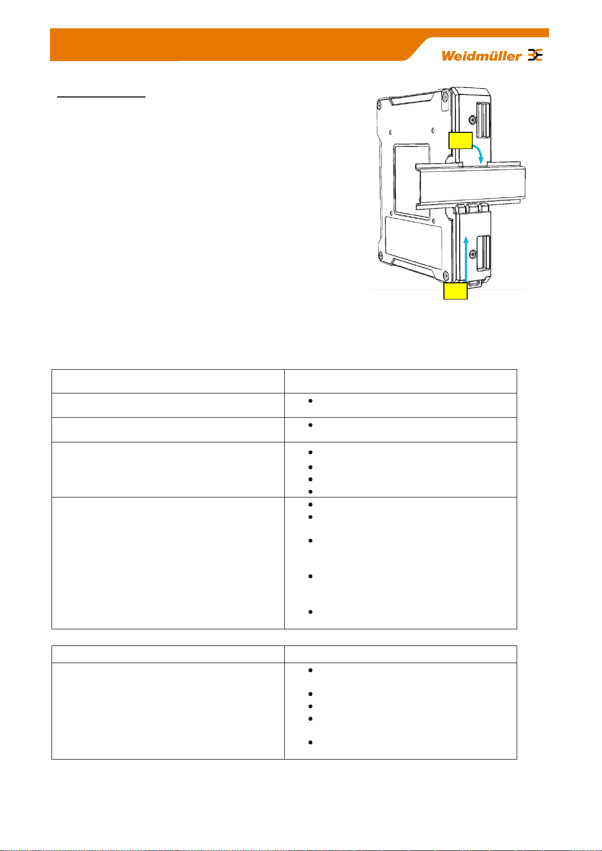
DIN-rail mounting:
Insert the top of the DIN-rail clip behind the upper edge of the DINrail (1). Then open the latch at bottom of the device by using a flatbladed screwdriver and fix the device on the DIN-rail by gently
pressing on the bottom (2).
To remove the Router from the DIN-Rail, simply reverse the steps
as described above.
5. Technical data
Copyright © 2013 Weidmüller Interface GmbH & Co. KG 8 / 103
All rights reserved. Reproduction without permission is prohibited.
Page 9

IPsec
Can be configured as an IPsec server or
client
Authentication with PSK (user ID, pass-
word) or X.509 certificates
Hardware encryption for faster data flow
rate
A maximum of 64 simultaneous connec-
tions (subnet with subnet or as IPsec
server)
Encryption algorithms DES-56, 3DES-
168, AES 128, AES 192, AES-256
Management
Configuration with web interface
(HHTP/HTTPS)
Web interface selectable in english or
german language
Configuration support through detailed
help information (tooltip)
Configurable Multi-user access with de-
finable rights
Support for SNMP v1/v3/v3
Event log / syslog
Other features
Modbus/TCP
The Modbus/TCP interface enables the control of the Router by a PLC. Following functions are imaged in the registers:
Cut & Alarm, status request & acknowl-
edgment
IPsec, on/off switchable generally
OpenVPN, separate status request and
activation / deactivation of the 10 possi-
ble OpenVPN connections
Diagnosis
„Remote Capture“- feature for network
diagnostics via a connected PC (Wire-
shark)
Monitoring
Client monitoring via ICMP protocol (ping
request) with alarm function in case of er-
ror
Interfaces
RJ45-Ports
2 * 10/100/1000BaseT(X)
USB-Port
option for future expansion
SCM card Reader
Save and restore the configuration using
a smart card (SIM card without mobile
provider data, only the storage capacity
of the chip will be used)
LED display
Signaling the status for power, device
status, Cut, Alarm, active VPN connec-
tion and an active 3G connection
Digital Outputs
"Alarm" -> Indicates a configurable net-
work status or error (24V out)
Copyright © 2013 Weidmüller Interface GmbH & Co. KG 9 / 103
All rights reserved. Reproduction without permission is prohibited.
Page 10

"VPN-active" -> Indicates an active VPN
connection (24 V out)
Digital Inputs
"Cut" -> Disconnects physically (link
down) the WAN port (24 V In)
"VPN-initiate" -> Enables a pre-
configured VPN connection (24 V In)
Reset-Button
Restore to the factory settings
Power
Input Voltage
1* 24 VDC (7 bis 36 Volt)
Current consumption
max. 600mA @ 24 VDC
Technical data (housing)
Housing
Metal, protection IP20
Dimensions (width, height, depth)
35 * 159 * 134 mm (without antenna)
35 * 255 * 134 mm (with 3G antenna)
Mounting
TS35 (DIN rail)
Environmental conditions
Operating Temperature
-20°C to +70°C
Storage Temperature
-20°C to + 85°C
Ambient Humidity
6 to 90% noncondensing
DSL and 3G/HSDPA
DSL
DSL Internet access by connecting an
external DSL modem via LAN or WAN
port
Free configuration of the PPPoE login
DynDNS
Support for automatic registration
UMTS/3G
(Only model IE-SR-2GT-UMTS/3G)
Built-in quad-band 3G / HSPA modem
21.1 Mbps peak downlink
5.8 Mbps peak uplink
GSM, GPRS, EDGE: 850 MHz, 900
MHz, 1800 MHz, 1900 MHz
UMTS, WCDMA, HSDPA, HSUPA: 850
MHz, 900 MHz, 1900 MHz, 2100 MHz
FCC, CE, FCC, IC, NCC, PTCRB, Bell,
AT&T
Approvals
Security
cULus (UL508)
EMC
FCC Part 15 Class A, EN 55022 Class A
EN61000-4-2 (ESD)
EN61000-4-3 (RS),
EN61000-4-4 (EFT)
EN61000-4-5 (Surge)
EN61000-4-6 (CS)
Copyright © 2013 Weidmüller Interface GmbH & Co. KG 10 / 103
All rights reserved. Reproduction without permission is prohibited.
Page 11
Shock
DIN EN 60068-2-29
Vibration
DIN EN 60068-2-6
Warranty
Period of time
3 years
Order data
Model name / Order number
LAN/WAN Router
IE-SR-2GT-LAN / 1345270000
LAN / WAN Router with integrated modem
UMTS/3G
IE-SR-2GT-UMTS/3G / 1345250000
Description of LED status indicators
LED
Signal
Meaning
PWR
off
The device is not powered
Flashing green
Device is turned on, the boot process is running
green
Device is turned on and ready to run
Status
off
The device is not powered
red
Error after boot process or recovering an image
Cut
off
CUT Input is not powered
red
A Cut event is triggered. LED lights up and the WAN
port is disabled
Alarm
off
No Alarm
red
An Alarm event is triggered
VPN active
off
No activated VPN tunnel.
green
Active VPN tunnel (triggered by external VPN key)
Only model
IE-SR-2GTUMTS/3G
3G (UMTS)
off
No active GSM / 3G / UMTS connection
Flashing yellow
Searching wireless network
yellow
Connected to a network provider but no active data
connection (Offline)
Flashing green
Connected to a network provider. Router activates the
connection on data flow (Standby)
UMTS/
3G
6. Hardware related functional descriptions
Copyright © 2013 Weidmüller Interface GmbH & Co. KG 11 / 103
All rights reserved. Reproduction without permission is prohibited.
Page 12

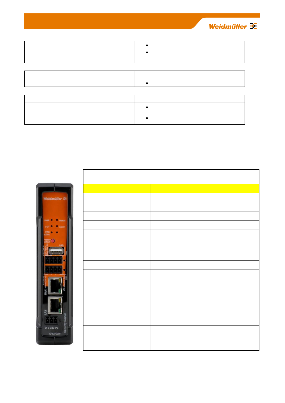
Description of device interfaces at top and front side
Only model IE-SR-2GT-UMTS/3G: Connector for UMTS/3G antenna at top side
Connector type: SMA female
USB 2.0 connector
4-pin connector („Cut WAN port“ and „Signalize Alarm“)
► 24 VDC input for Cut signal (Disabling WAN interface) and
► 24 VDC output for signaling an alarm event
Note: Corresponding socket connector is included
4-pin connector ( „VPN initiate“ and „VPN active“)
► 24 VDC input for initiating a VPN tunnel (Predefined OpenVPN tunnel)
► 24 VDC output for signaling an active VPN tunnel
Note: Corresponding socket connector is included
RJ45-Connector WAN (10/100/1000BaseTX)
RJ45-Connector LAN (10/100/1000BaseTX)
3-pin connector for 24V DC power supply
Note: Corresponding socket connector is included
Description of device
interfaces at rear side
SCM slot / socket
SIM memory card reader for
external backup and restore
of the Router configuration
3G slot / socket
Slot for mobile SIM card (only
3G/UMTS model)
UMTS/
3G
Connector for
UMTS / 3G
antenna of type
SMA female
Any external
antenna can be
used which is
compliant to
following parameters:
Diversity Support:
900/1900/2100
MHz
Antenna Connector:50 Ohm
compatible
Copyright © 2013 Weidmüller Interface GmbH & Co. KG 12 / 103
All rights reserved. Reproduction without permission is prohibited.
Page 13

Pin number
SIGNAL NAME (MDI)
10/100Base T(x) 1000Base T
1
TX + BI_DA+
2
TX - BI_DA-
3
RX + BI_DB+
4
NC BI_DC+
5
NC BI_DC-
6
RX - BI_DB-
7
NC BI_DD+-
8
NC BI_DD-
Pin number
SIGNAL NAME
1
24V DC (VCC)
2
Initiate VPN (24 V In)
3
VPN active (24 V Out)
4
GND
Pin number
SIGNAL NAME
1
24V DC (VCC)
2
Cut (Disabling WAN-Port, 24 V
In)
3
Signalize Alarm (24 V Out)
4
GND
Pin number
SIGNAL NAME
1
24V DC
2
GND
3
PE
Pin assignment of power supply connector
Note: Allowed input voltage range from 7 to 36 VDC (24 VDC typical)
Pin assignment of RJ45 Ethernet ports (LAN and WAN)
Pin assignment of 4-pin connector for „VPN initiate“ and „VPN active“
Pin assignment of 4-pin connector for „Cut WAN port“ and „Signalize Alarm“
Copyright © 2013 Weidmüller Interface GmbH & Co. KG 13 / 103
All rights reserved. Reproduction without permission is prohibited.
Page 14
Pin number
SIGNAL NAME
1
VDC
2
D -
3
D+
4
GND
Note
The configuration of the device can be done either via LAN or WAN RJ45 ports.
Pin number
SIGNAL NAME
1
VCC 5 Volt
2
RESET
3
CLOCK
4
n/c
5
GND
6
n/c
7
I/O
8
n/c
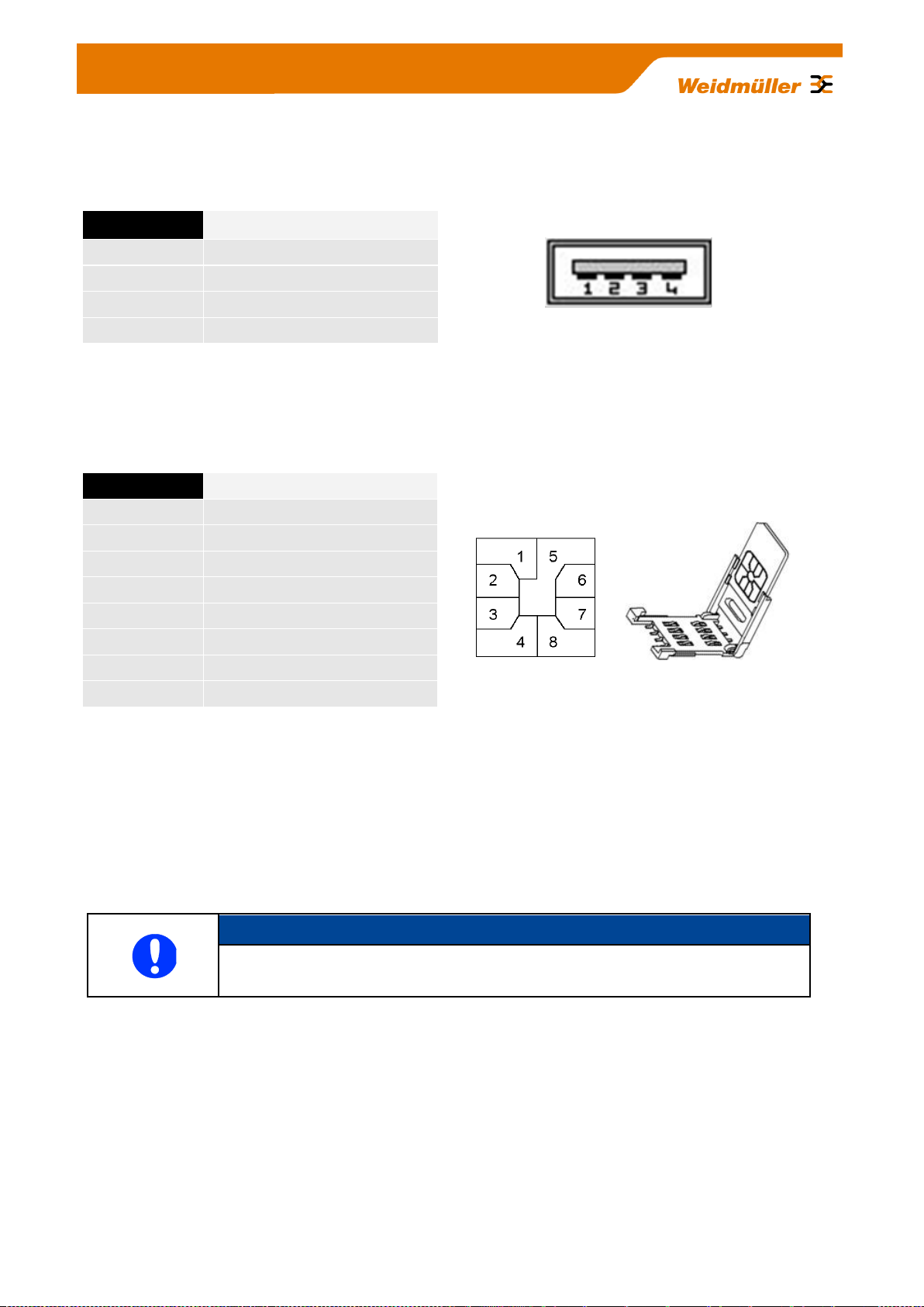
Pin assignment of USB 2.0 connector
The USB interface is intended for connecting peripheral devices (USB 2.0). The connector is without function
in the current firmware version, but is optional for future planned applications.
Pin assignment of Smartcard Reader (ISO 7816 Standard)
The integrated SIM card reader is intended for saving and restoring the configuration data.
7. Initial start-up / Getting Started
Configuration of the Router by using an Internet browser
Connect the unit to a 24V DC (3-pin plug) power source. The corresponding plug is included.
During the initial boot phase, the PWR LED is flashing. The Router is ready when the PWR LED is lit
constantly (after about 30 seconds).
Connect the Router to the Ethernet interface of a configuration PC using a RJ45 network cable.
It is possible to use a standard Ethernet patch cable or a crossed network cable. By default both Ethernet
ports are configured with autonegotiation.
Copyright © 2013 Weidmüller Interface GmbH & Co. KG 14 / 103
All rights reserved. Reproduction without permission is prohibited.
Page 15
Important note
The Router’s Web server partly is using Java script for parameter settings (e.g. if you
want to apply or deleting a configured Open VPN session).
Please ensure that the Web browser your a using is allowed to run Java script.
For Router configuration you do NOT need to install Java runtime software (for
executable Java applets) because only Java script will be used. Standard Web
browsers by default are able to run Java script code.
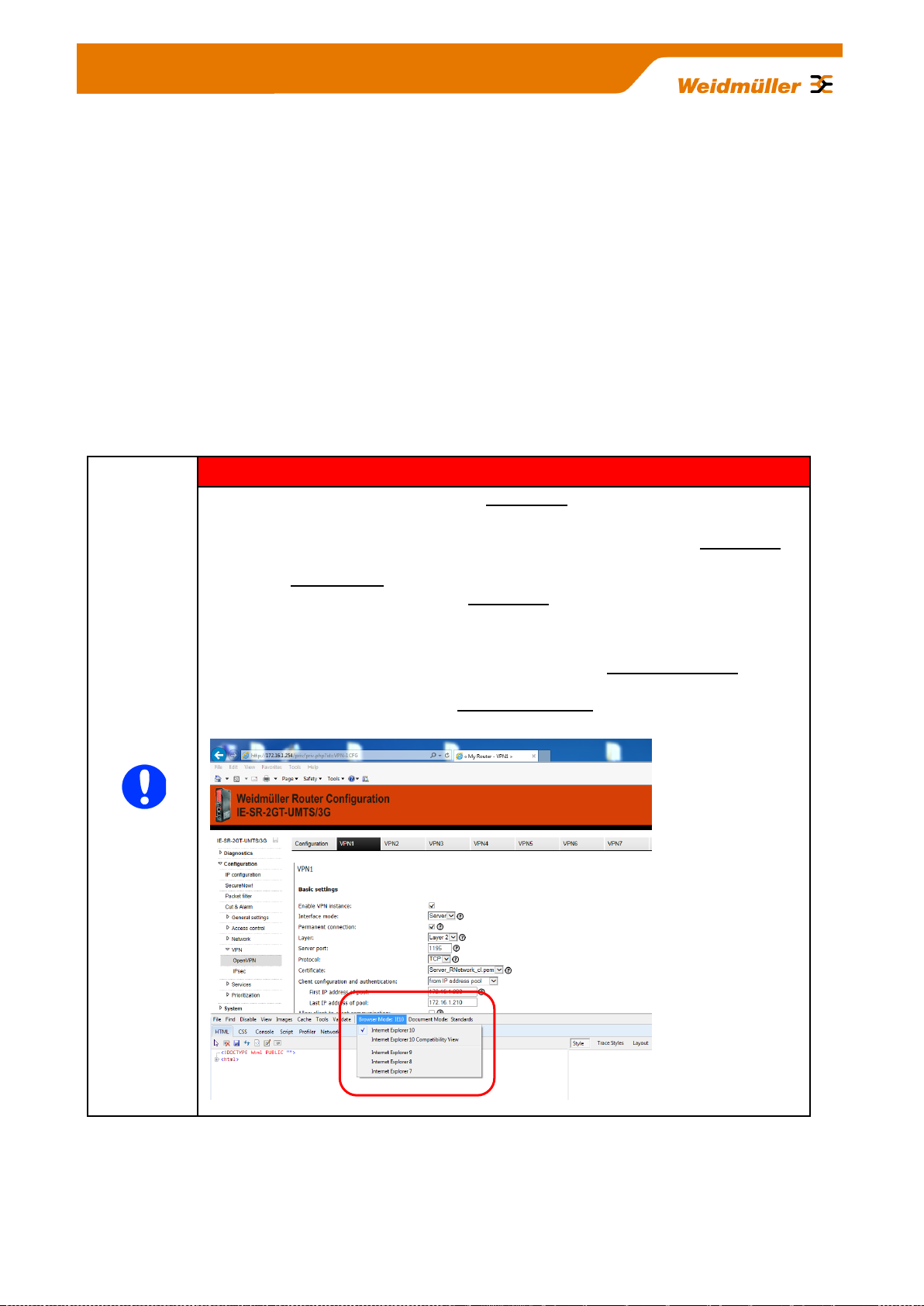
If some “Apply” buttons are not working (seems to be without function) and if you are
using Internet Explorer 10 please verify that you are using Bowser Mode IE10 to
ensure that Java script is running properly. To validate the browser mode press key
F12 and activate – if not set – mode Internet Explorer 10 as shown in the screenshot
below.
The configuration and control of the Router is to done via the integrated Web server. Any Internet browser
(Microsoft Internet Explorer or Mozilla Firefox) can be used.
When delivered, the Web interface of the Router can be achieved from both LAN and WAN port.
To access the Web interface of the Router the IP address of the connected PC has to be in the same logical
network (IP address range) as the Router.
The default IP addresses and net masks of the Router are:
LAN port : 192.168.1.110 / 255.255.255.0
WAN port : 192.168.2.110 / 255.255.255.0
Starting the Web interface
Start your Web browser and enter the IP address of the connected Router port into the browser’s address
line.
Copyright © 2013 Weidmüller Interface GmbH & Co. KG 15 / 103
All rights reserved. Reproduction without permission is prohibited.
Page 16

Note
If the login prompt does not appear, please check the network LED's, if the devices are
connected to the network correctly. If problems still persist, please check the proxy and
firewall settings of the local PC
Screenshot of
the Login page
Now the login prompt of the Router should appear for input „User
name“ and „Password“.
Default values (factory settings) for Login:
User name : admin
Password : Detmold
Confirm your input by pressing the OK button.
Now the Router homepage is displayed. This page corresponds to the menu item "Diagnostic System
Status." On this page the most important configuration and status informations are summarized.
Note: Some fields are linked with a hyperlink to jump directly into the corresponding menu item.
Copyright © 2013 Weidmüller Interface GmbH & Co. KG 16 / 103
All rights reserved. Reproduction without permission is prohibited.
Page 17

8. Reset to factory default settings by external push button
By pressing the push button "Factory Default" the security Router can be reset at any time and regardless of
the configuration to the default settings (factory settings).
How to set the factory settings:
1. Power off the Router
2. Press the button „Factory Default“ and keep it hold down
3. Power on the Router and keeping button „Factory Default“ pressed while Router is booting
4. Release button „Factory Default“ when Power LED starts flashing fast (around 10 seconds after power on)
5. Wait until Power LED is glowing constantly green
Now the Router is ready to run with factory default settings.
Default factory settings of the Router:
Language: Englisch user interface
Operation mode : IP Router
IP address LAN port: 192.168.1.110 (static value)
Subnet mask: 255.255.255.0
NAT (Masquerading) on LAN port: Not activated
IP address WAN port: 192.168.2.110 (static value)
Subnet mask: 255.255.255.0
NAT (Masquerading) on WAN port: Not activated
Default gateway: No entry
DNS: DNS relay not activated
Firewall (Packet filter): By default, data traffic in both directions between LAN and WAN is
allowed on both level Layer 2 and Layer 3. For that the packet filter
contains two default rules, called "Allow_L2" and "Allow_L3" (allow traffic
at Layer 2 and 3) which allows as "white lists" all network traffic.
IP routing No static routes
Dynamic routing (OSPF, RIP) disabled
SNMP / DHCP / DNS Disabled
VPN: Disabled
Data prioritization Disabled
Only model IE-SR-2GT-UMTS/3G
3G Modem Disabled
Copyright © 2013 Weidmüller Interface GmbH & Co. KG 17 / 103
All rights reserved. Reproduction without permission is prohibited.
Page 18

9. Using the Weidmüller Router-Search-Utility
The software tool Weidmüller Router- Search-Utility can be used to find Weidmüller Routers and detect
theirs IP addresses within a switched network. This software is very helpful if you don’t know the current IP
address of a Router. This can e.g. happen in cases that you have forgotten the current IP configuration or
you have lost the Router access in case of configuring an unintended IP address. The main features of the
software are
Detecting a Router and displaying parameters like Device name, MAC address and IP address with
Subnet mask
Change the IP address of a detected Router
Open the web interface of a detected Router
You may download the Weidmüller Router-Search-Utility from the Weidmüller web site using the following
path:
1. Open www.weidmueller.com/IE
2. Select section “Industrial Ethernet“ „Software”
3. Select category “Additional Software (Configuration utilities, Drivers and MIB-files)“
4. Select category “Industrial Security Router (IE-SR-2GT-LAN, …3G/UMTS)“
5. Download “ Weidmueller_Router_Search_Utility.zip”
Alternatively you can download this software from this web page:
1. Open www.weidmueller.com
2. Select Downloads
3. Select Software
4. Select Industrial Ethernet
5. Download from section Industrial Security Router (Firmware and Software for IE-SR-2GT-LAN/3G/UMTS)
Copyright © 2013 Weidmüller Interface GmbH & Co. KG 18 / 103
All rights reserved. Reproduction without permission is prohibited.
Page 19

10. Basic description of the configuration interface (menu items)
The menu structure of the web Interface is divided into 4 main sections:
Section Diagnostics
► Displays system status data
► Display of logging information
► Displays current interface parameters (LAN/WAN/3G)
► Feature for testing the data communication between the Router and other
Ethernet devices (Ping test)
Section Configuration
► Setting of operation mode (eg „IP Router“) and basic network parameters (IP addresses,
Default gateway)
► Setting of firewall rules (Packet filter and an additional auto learning feature called
„SecureNow“ to assist the creation of packet filtering rules)
► Configuration of general system data (name, location, contact person, date / time,
language interface, etc.)
► Certificate Management for VPN connections
► User administration (assignment of rights)
► IP-Routing (static, dynamic) and IP address management (Masquerading, 1:1 NAT,
Portforwarding)
► Configuration of VPN connections (OpenVPN, IPsec)
► Configuration of general network services (e.g. DHCP, DBS, SNMP)
► Prioritization of network traffic (Layer-2 and Layer-3 level)
Section System
► Backup and restore of device configuration, Update firmware, Reboot)
Section Informations
► Display of technical data and hardware information (eg serial number and MAC address)
Copyright © 2013 Weidmüller Interface GmbH & Co. KG 19 / 103
All rights reserved. Reproduction without permission is prohibited.
Page 20

11. Explanation of the menu items of web interface in
chronological order
Figure 1: Diagnostics Systemstatus
Startup screen of the web interface after login. Displays current configuration and status data.
Figure 2: Diagnostics Eventlog Tab State
Display events and error messages that have occurred.
Copyright © 2013 Weidmüller Interface GmbH & Co. KG 20 / 103
All rights reserved. Reproduction without permission is prohibited.
Page 21

Figure 3: Diagnostics Eventlog Tab Configuration
Event and error messages can be sent to a syslog server (PC on the network) and also sent as emails.
Figure 4: Diagnostics WAN
Display of the current status of the WAN port.
Figure 5: Diagnostics LAN
Display of the current status of the LAN port.
Copyright © 2013 Weidmüller Interface GmbH & Co. KG 21 / 103
All rights reserved. Reproduction without permission is prohibited.
Page 22

Screenshot of a 3G-Router with
inserted SIM Card.
The Router is connected to the
Internet by provider Vodafone.
Figure 6: Diagnostics 3G
Displays the current status of the 3G mobile connection.
Figure 7: Diagnostics Ping-Test
Allows sending of ICMP packets (ping) to test network connections between the Router and other Ethernet
devices.
Copyright © 2013 Weidmüller Interface GmbH & Co. KG 22 / 103
All rights reserved. Reproduction without permission is prohibited.
Page 23

Figure 8: Diagnostics Remote-Capture
By using the "remote capture" function data packets on both the LAN and the WAN port of the
Router can be recorded for diagnostic purposes. The receiver of the diagnostic data is a PC which
must have installed the tool "Wireshark".
How to use please refer to application note in Appendix C3.
Figure 9: Configuration IP Configuration
This is the basic configuration window of the Router for assignment of IP addresses on the LAN and WAN
port. Each of the two interfaces can be configured with static or dynamic (DHCP) IP addresses. For models
of type IE-SR-3GT-UMTS/3G (as shown above) additionally a section „3G“ will be displayed to configure the
3G connection.
Copyright © 2013 Weidmüller Interface GmbH & Co. KG 23 / 103
All rights reserved. Reproduction without permission is prohibited.
Page 24
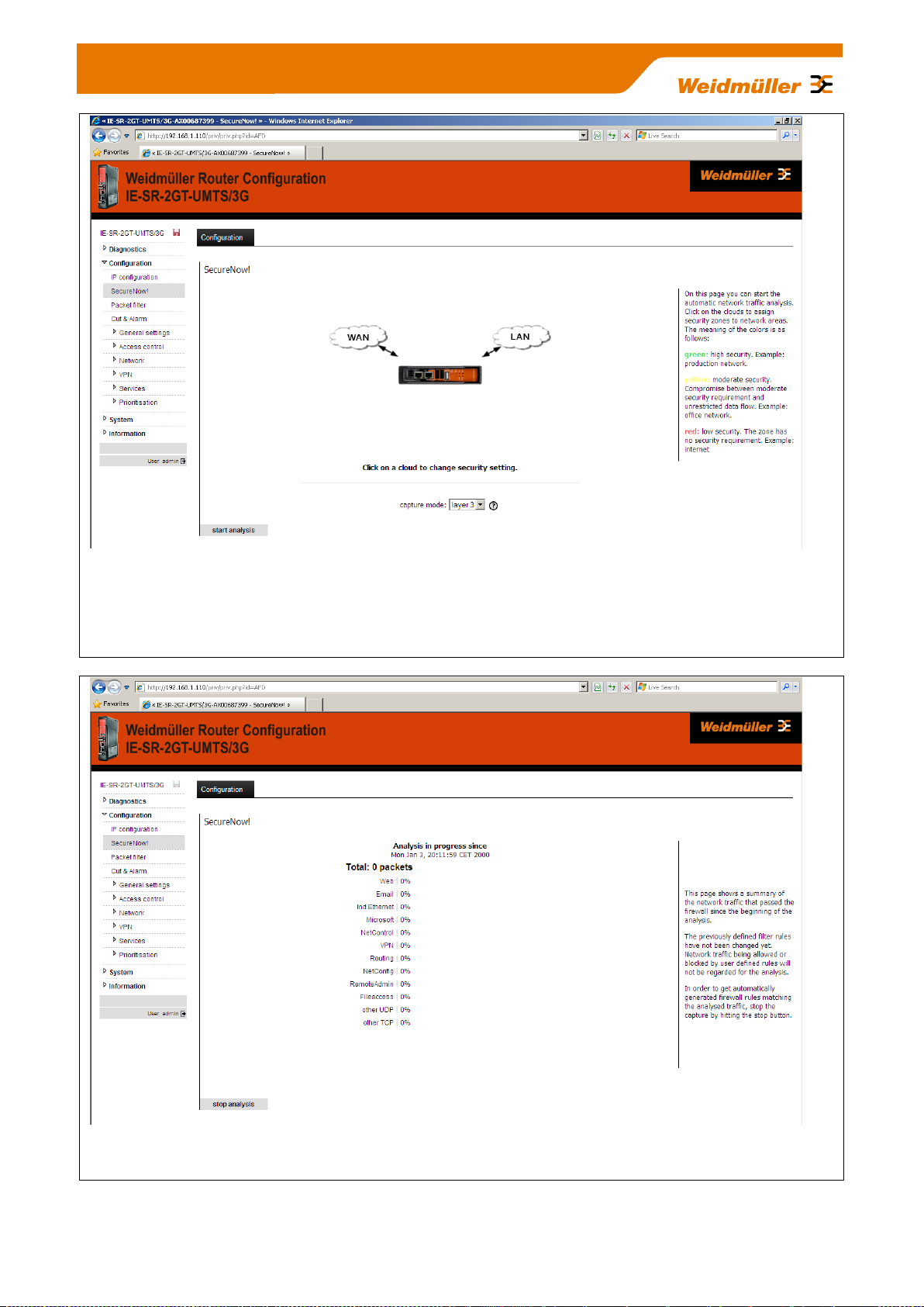
Figure 10: Configuration SecureNow
This is an auxiliary function for "independent learning" firewall rules based on temporary recording of data
traffic. By pressing the button "Start Analysis" button the Router begins to analyze the network traffic (ports
LAN, WAN and possibly UMTS/3G). As a result, the Router will provide a table showing the recorded TCP
packets and protocols as well as a proposal for the setting of firewall filtering rules.
Figure 11: Configuration SecureNow „running analysis“
Window screen after starting the network analysis displaying the current network traffic.
Copyright © 2013 Weidmüller Interface GmbH & Co. KG 24 / 103
All rights reserved. Reproduction without permission is prohibited.
Page 25
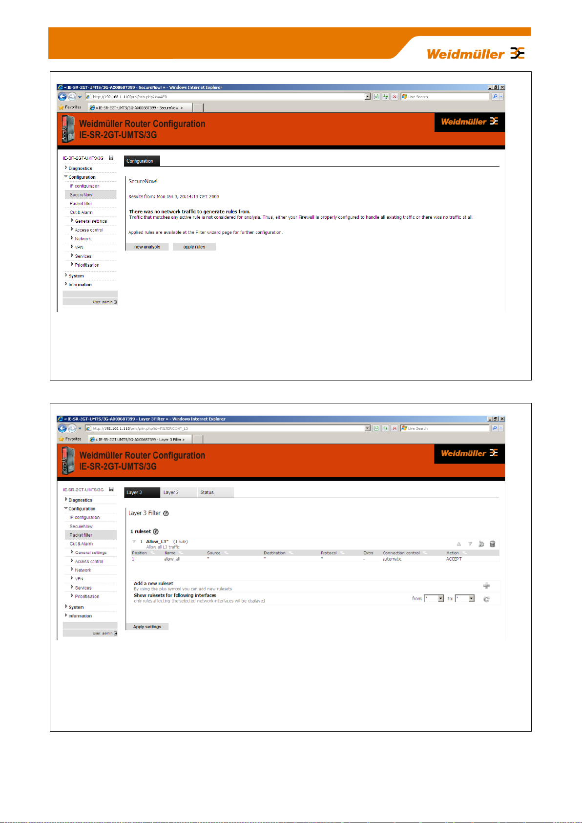
Figure 12: Configuration SecureNow „Analysis stopped“
Window after exiting the network analysis with a proposed indication of firewall filtering rules. If you click the
button "apply rules", the firewall will be updated with the proposed rules and immediately activated. The
changes are not saved automatically, so that e.g. "wrong" filter rules can be removed by a Router restart.
Then previous filter rules would be valid again.
Figure 13: Configuration Packet filter Tab „Layer 3“
This is the window for the manual configuration of firewall filter rules based on Layer 3 (IP layer). The
screenshot shows the firewall settings as delivered with the default rule "Allow_L3*". This rule says that any
IP protocol (*) and any traffic regardless the direction (source and destination=*) is allowed. The result is that
- on delivery - the firewall is "open" on layer 3.
Fore more detailed information about using the packet filter please refer to Appendix A3.
Copyright © 2013 Weidmüller Interface GmbH & Co. KG 25 / 103
All rights reserved. Reproduction without permission is prohibited.
Page 26

Figure 14: Configuration Packet filter Tab „Layer 2“
This is the window for the manual configuration of firewall filter rules based on Layer 2 (MAC layer). The
screenshot shows the firewall settings as delivered with the 2 default rules "Allow_L2*" and „ARP*“ (Address
resolution protocol). The rule Allow_L2* allows transmitting any Ethernet frame type (*) and any traffic
regardless the direction (source and destination mac address =*). The result is that - on delivery - the firewall
is "open" for layer 2.
Figure 15: Configuration Packet filter Tab „Status“
Overview of transmit and receive activities of the Ethernet interfaces. In addition, firewall-related information
is displayed under the heading "Filter Log".
Copyright © 2013 Weidmüller Interface GmbH & Co. KG 26 / 103
All rights reserved. Reproduction without permission is prohibited.
Page 27

Figure 16: Configuration Cut & Alarm Tab „Configuration“
In this menu it can be configured how the events "Cut" and "Alarm" - after they have occurred – will be reset
(either manually by clicking on a button on the tab “State” or automatically after an elapsed time).
For more information please refer to Appendix C2 (Method 2).
Figure 17: Configuration Cut & Alarm Tab „State“
Displays the current status of the events
"Internal Cut" triggered eg by a special firewall rule
"External Cut" Input of 24 VDC at 4-pin connector (at front side of the Router)
"Alarm" triggered eg by a special firewall rule or by the function „Client monitoring“
By clicking on the buttons „Reset Cut signal“ and „Reset alarm signal“ you can manually reset the events
„Internal Cut“ and „Alarm“. The "External Cut" will automatically be reset if the 24 VDC at the 4-pin connector
will be removed.
Copyright © 2013 Weidmüller Interface GmbH & Co. KG 27 / 103
All rights reserved. Reproduction without permission is prohibited.
Page 28

Note:
The Router has no battery-buffered, but
a capacity-buffered system clock. If the
Router is powered-off more than 30
minutes, the date and time values will
be reset to factory default settings (Date
= date of production e.g. 01/01/2012,
Time 00:00).
Figure 18: Configuration General settings System data Tab „Configuration“
Configuring application-related data of the Router (free text).
Figure 19: Configuration General settings Date & time Tab „Configuration“
Setting of date, time and time zone. Alternatively, the date/time setting can be configured via using the "Net-
work Time Protocol" and accessing an external NTP server.
Copyright © 2013 Weidmüller Interface GmbH & Co. KG 28 / 103
All rights reserved. Reproduction without permission is prohibited.
Page 29
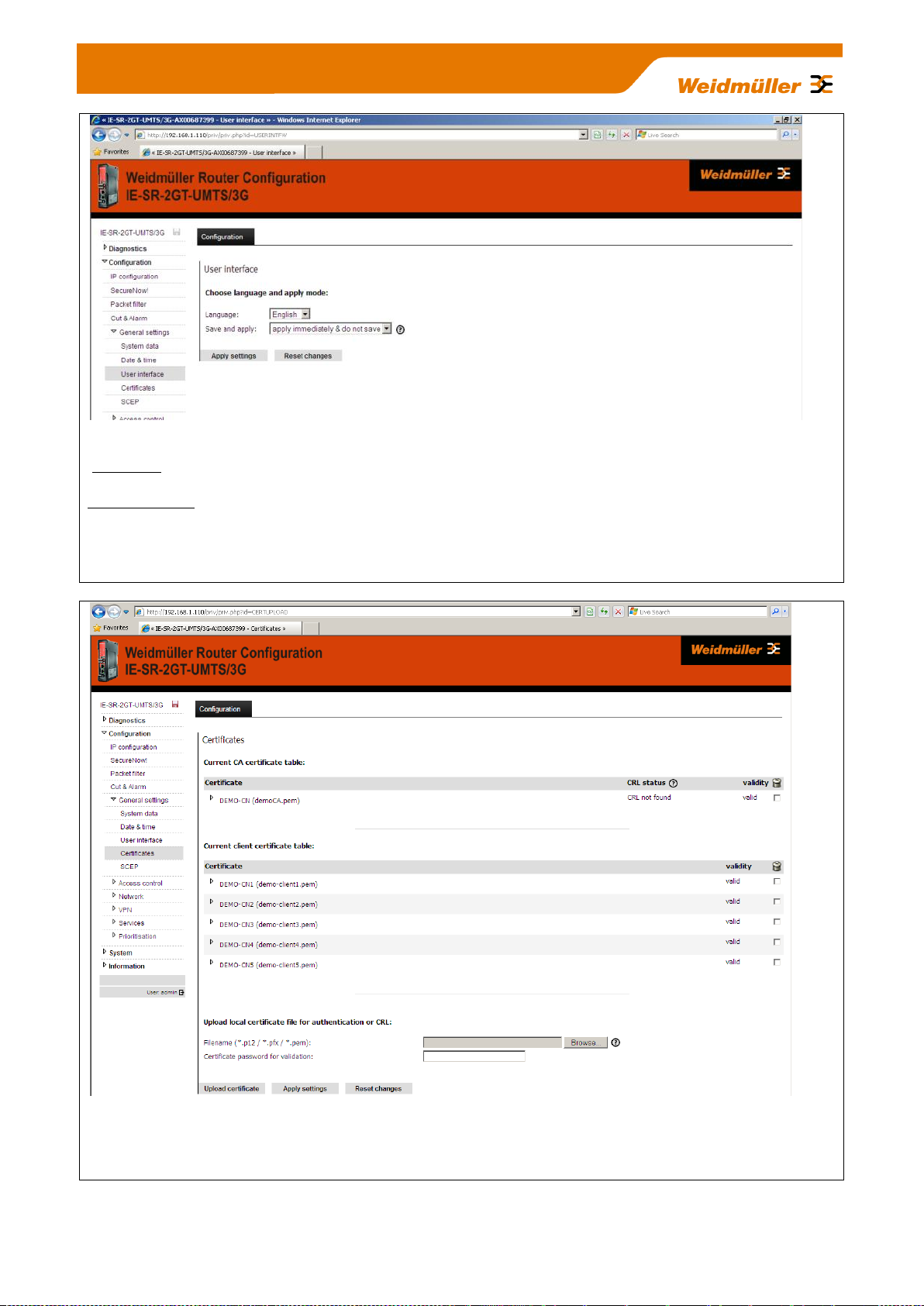
Figure 20: Configuration General settings User interface Tab „Configuration“
Language Setting the language (German or English) of the Web interface.
Save and apply Setting the behaviour of the button "Activate" respectively „Save“ in the configuration
windows. If you chose the entry „Apply immediately and do not save“ then configuration changes will be
immediately activated but not saved. If you chose the entry „Save only and do not apply“ then the button
named „Apply“ in the configuration windows will be changed to a button named „Saved“. In this case all done
changes will be only saved and not activated. Saved changes come into effect after a restart.
Figure 21: Configuration General settings Certificates Tab „Configuration“
Adding or deleting of certificates for VPN applications (used for both IPsec and OpenVPN).
How to use certificates (CA Root, Server, Client) please refer to Appendix B1 (Link to document
TechNote_Router_RemoteAccess_via_MeetingPoint_V1_??.pdf).
Copyright © 2013 Weidmüller Interface GmbH & Co. KG 29 / 103
All rights reserved. Reproduction without permission is prohibited.
Page 30
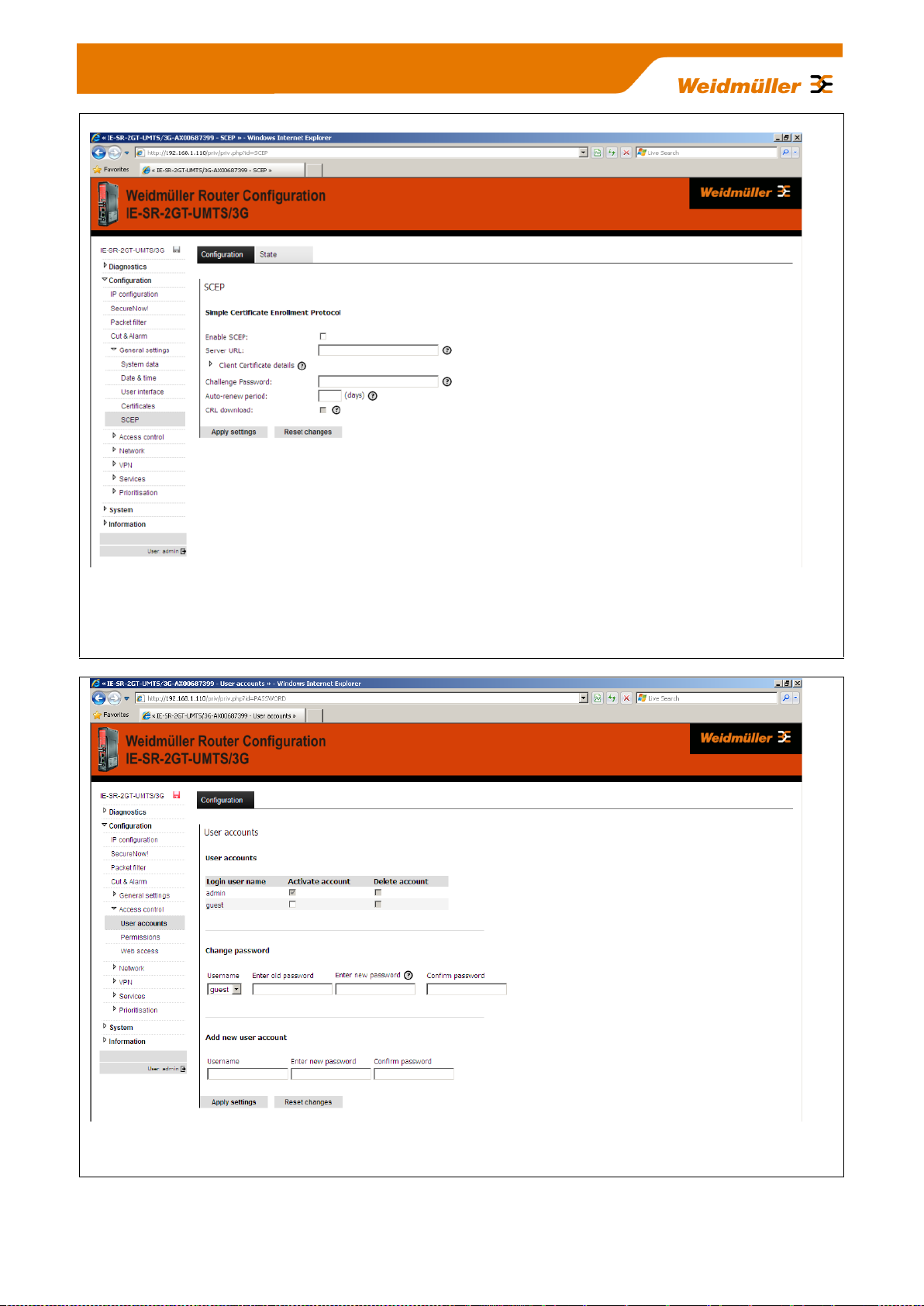
Figure 22: Configuration General settings SCEP Tab „Configuration“
Configuration of the Router for online access to certificates which are stored on a centralized online certifica-
te server (SCEP Simple Certification Enrollment Protocol). When setting up certificate-based VPN connections, the necessary certificates can be obtained directly from a SCEP server.
Figure 23: Configuration Access control User accounts Tab „Configuration“
Create and delete other user accounts
Copyright © 2013 Weidmüller Interface GmbH & Co. KG 30 / 103
All rights reserved. Reproduction without permission is prohibited.
Page 31

Figure 24: Configuration Access control Permissions Tab „Configuration“
Detailed assignmnet of individual rights for the created user accounts.
Note: The Administrator account always has full access. It cannot be deleted.
Figure 25: Configuration Access control Web access Tab „Configuration“
Select the possible access modes of the web interface (via http and / or https). For models of type IE-SR-
3GT-UMTS/3G additionally section „3G“ (as shown above) will be displayed to allow access to the Webinterface via 3G connection.
Copyright © 2013 Weidmüller Interface GmbH & Co. KG 31 / 103
All rights reserved. Reproduction without permission is prohibited.
Page 32

Figure 26: Configuration Network DNS Tab „Configuration“
Registration of up to 3 DNS servers for name resolution. The Router acts as a DNS relay server.
Figure 27: Configuration Network IP Routing Tab „Configuration“
Registration of static IP routes and activating/deactivating of dynamic routing. For dynamic routing both can
be selected the RIP and the OSPF protocol. Up to 10 static IP routes can be configured.
Copyright © 2013 Weidmüller Interface GmbH & Co. KG 32 / 103
All rights reserved. Reproduction without permission is prohibited.
Page 33

Factory default configuration without any entry
Figure 28: Configuration Network IP Routing Tab „State“
Display of currently valid routing table.
Figure 29: Configuration Network Forwarding Tab „Configuration“
Configuring standard port forwardings (IP address with port) and pure IP address forwardings. Additonally for
each forwarding the feature SNAT (Source network address translation) can be activated to hide the original
source.
„IP address forwarding“ can be configured using an IP address and a wildcard port number (*) instead of a
fixed port number. With this features it is possible to get access to an Ethernet device behind a masqueraded
interface only by IP address. From the behavior this fea-ture is similar to a virtual mapping giving an Ethernet
device a second public IP address.
Figure 30: Configuration Network Forwarding Tab „Configuration“ (2 Forwardings configured)
Copyright © 2013 Weidmüller Interface GmbH & Co. KG 33 / 103
All rights reserved. Reproduction without permission is prohibited.
Page 34

Figure 31: Configuration Network 1:1 NAT Tab „Configuration“
Configuration of the mapping (assignment) of IP address ranges between LAN and WAN port, and vice-
versa.
For more detailed information please refer to Appendix A2.
Figure 32: Configuration Network Network groups Tab „Configuration“
Creating groups with "speaking" names for ranges of IP addresses (Layer 3). A network group always
contains a range of IP addresses with specified subnet (eg 192.168.1.0/24). A network group can contain a
set of single IP addresses and complete IP address ranges. Network groups can be used instead of IP
address ranges if you will create firewall filtering rules (See menu Configuration Packet filters Layer 3).
Copyright © 2013 Weidmüller Interface GmbH & Co. KG 34 / 103
All rights reserved. Reproduction without permission is prohibited.
Page 35

Figure 33: Configuration Network Hardware groups Tab „Configuration“
Creating groups with "speaking" names based on MAC addresses (layer 2). A hardware group can contain
any number of MAC addresses (for example, 00:15:7E:D9:09:00). Hardware groups can be used for better
readability than individual MAC addresses if you will create firewall filtering rules (See menu Configuration
Packet filters Layer 2).
Figure 34: Configuration Network Ethernet Tab „Configuration“
Setting the transmission parameters of the LAN / WAN hardware interfaces.
Copyright © 2013 Weidmüller Interface GmbH & Co. KG 35 / 103
All rights reserved. Reproduction without permission is prohibited.
Page 36

Screenshot of OpenVPN menu tab „Configuration“
with factory defaults (without configured OpenVPN
sessions)
Figure 35: Configuration VPN OpenVPN Tab „Configuration“
The OpenVPN menu allows to create and establish virtual private network connections based on the
OpenVPN implementation. The Router can be configured both as OpenVPN client and OpenVPN server
either based on Layer 2 (Bridging) or on Layer 3 (Routing). A maximum of 10 OpenVPN connections (either
as client or as server) can be configured and started at the same time. Each VPN connection can be
configured individually at Tab’s VPN1…VPN10.
Note: OpenVPN connections can only be used with encryption based on certificates.
On each configured OpenVPN server connection theoretically any number of remote OpenVPN clients can
be connected (only limited by the hardware performance of the Router).
Figure 36: Configuration VPN OpenVPN Tab „VPN1“
Screenshot of a configured OpenVPN-Client at tab VPN1
Copyright © 2013 Weidmüller Interface GmbH & Co. KG 36 / 103
All rights reserved. Reproduction without permission is prohibited.
Page 37

Screenshot of OpenVPN menu „Tab Configuration“
showing 2 configured OpenVPN sessions at a
glance.
Figure 37: Configuration VPN OpenVPN Tab „VPN2“
Screenshot of a configured OpenVPN-Server at tab VPN2.
Figure 38: Configuration VPN OpenVPN Tab “State”
This screenshot is displaying the status of a configured OpenVPN-Client session (L3, VPN1, currently dis-
connected) and an OpenVPN-Server session (L3, VPN2, currently no connected remote clients).
Figure 39: Configuration VPN OpenVPN Tab “Configuration”
After configuration of OpenVPN sessions the configured connected will be displayed at a glance in this
menu.
How to configure OpenVPN connections please refer to Appendix B (Link to technical documents
about OpenVPN based remote access scenarios).
Copyright © 2013 Weidmüller Interface GmbH & Co. KG 37 / 103
All rights reserved. Reproduction without permission is prohibited.
Page 38

Figure 40: Configuration VPN IPsec Tab „Configuration“
The IPsec menu allows to create and establish virtual private network connections based on the standard
IPsec implementation. The Router can be configured both as IPsec client and IPsec server.
IPsec allows the encryption of the complete communication flow between the Router and a remote site on IP
level. IPsec provides encryption of subnets, which are located behind the respective VPN peers.
IPsec connections can be used with both PSK encryption (pre-shared key using user name and password)
as well as certificate based encryption.
Implemented IPsec features:
Key exchange: IKE (Internet Key Exchange) basedon ISAKMP (Internet Security Association and Key
Management Protocol)
IKE-Phases: Main-Mode (Phase 1) and Quick-Mode (Phase 2)
Authentication: X.509-certificates or Pre-shared-key
DH groups: DH group 1 MODP 768, DH group 2 MODP 1024, DH group 5 MODP 1536
Data integrity: MD5 (128bit), SHA1 (160bit)
Encoding: DES (64bit), 3DES (192bit), AES (128bit), AES (192bit), AES (256bit)
Integrated hardware-based encoding
Ipsec mode: ESP tunnel
Maximum number of Ipsec connections: 64
NAT-Traversal: Yes
Dead-Peer-Detection: Yes
Note: By default the Router uses the parameters AES128, MD5, DH group 2 for Main-Mode and
AES128, SHA1 for Quick-Mode.
Authentication by „Aggressive-Mode is due to security reasons not supported!
Copyright © 2013 Weidmüller Interface GmbH & Co. KG 38 / 103
All rights reserved. Reproduction without permission is prohibited.
Page 39

Figure 41: Configuration Services DHCP Server Tab „Configuration“
In operating mode "IP Router", the built-in DHCP server can be used for allocating IP addresses on both
LAN-side and WAN side. By default (factory settings) the DHCP server is switched off.
Note:
The range of the IP addresses – which will be allocated to connecting DHCP clients - must be in the same
range as the IP address of the Router interface (LAN or WAN).
Alternatively, the Router can be configured as a DHCP relay. DHCP requests from clients which require an
IP address are then forwarded to the "real" DHCP server.
Copyright © 2013 Weidmüller Interface GmbH & Co. KG 39 / 103
All rights reserved. Reproduction without permission is prohibited.
Page 40

Figure 42: Configuration Services Dynamic DNS Tab „Configuration“
This feature allows the Router - if connected to the Internet using dynamic IP address allocation - to be
accessed by a „speaking“ name via the public Dynamic DNS service of provider „DynDNS.org“.
Figure 43: Configuration Services Web server Tab „Configuration“
Via this menu item the access protocol to the Web interface (http or https) can be configured.
Copyright © 2013 Weidmüller Interface GmbH & Co. KG 40 / 103
All rights reserved. Reproduction without permission is prohibited.
Page 41

Figure 44: Configuration Services SNMP Tab „Configuration“
Activation / deactivation of the SNMP protocol (Simple Network Management Protocol). Versions
v1/v2/v3 are supported. Router data can be requested using Standard MIB-II.
Note: Currently no SNMP-traps are implemented.
Figure 45: Configuration Services Modbus TCP Tab „Configuration“
Activation / deactivation of the integrated ModbusTCP-Server. Allows external Ethernet controllers that und-
erstand the ModbusTCP protocol to query Router states and control information. Using the ModbusTCP
protocol e.g. VPN connections (IPsec and OpenVPN) can be activated and deactivated. Additionally events
like „Cut“ or „Alarm“ can be monitored and reset (acknowledged).
Copyright © 2013 Weidmüller Interface GmbH & Co. KG 41 / 103
All rights reserved. Reproduction without permission is prohibited.
Page 42

Figure 46: Configuration Services Client Monitoring Tab „Configuration“
Allows the monitoring (still alive?) of network devices via a cyclic query using the ICMP protocol (ping re-
quest). As an action if a monitored Ethernet device is no longer available an „Alarm“ or a „Cut“ event can be
triggered. Additionally the connection to a mail server and a target mail address can be configured to send
the information about a lost connection of a monitored device by mail.
Fore more detailed information please refer to Appendix C2 (Method 3).
Figure 47: Configuration Prioritization WAN Tab „Configuration“
With this feature outgoing traffic on the WAN interface can be classified and prioritized. The prioritization
("traffic shaping") can be configured on both Layer 2 (based on MAC addresses) and at Layer 3 (IP
addresses and protocols).
Copyright © 2013 Weidmüller Interface GmbH & Co. KG 42 / 103
All rights reserved. Reproduction without permission is prohibited.
Page 43

Note:
This option is only available for Router model IE-SR-2G-
UMTS/3G which is equipped with an integrated 3G modem.
Figure 48: Configuration Prioritization LAN Tab „Configuration“
With this feature outgoing traffic on the LAN interface can be classified and prioritized. The prioritization
("traffic shaping") can be configured on both Layer 2 (based on MAC addresses) and at Layer 3 (IP
addresses and protocols).
Figure 49: Configuration Prioritization 3G Tab „Configuration“
With this feature outgoing traffic on the 3G wireless interface can be classified and prioritized. The
prioritization ("traffic shaping") can be configured on both Layer 2 (based on MAC addresses) and at Layer 3
(IP addresses and protocols).
Copyright © 2013 Weidmüller Interface GmbH & Co. KG 43 / 103
All rights reserved. Reproduction without permission is prohibited.
Page 44

Figure 50: System Backup settings Tab „System“
With this menu item, the Router configuration can be stored or restored to/from the file system of the
connected computer. The exported configuration file is of extension type <name>.cf2 and encrypted.
Note: For creating a configuration backup file (.cf2) always the configuration currently stored in the Flash
memory will be used. Please save the configuration to Flash memory before creating a backup file.
Figure 51: System Software update Tab „System“
With this menu item a firmware update can be carried out.
The firmware update can be done via a FTP, TFTP or HTTP server or by a browser upload getting the firm-
ware file directly from the connected configuration PC.
The easiest way to update the Router with a new firmware is to use the function „Update by browser
upload“.
Additionally it can be determined whether the Router should be reset to factory default settings after the
firmware update. If not set then the Router will use current configuration after firmware update.
Copyright © 2013 Weidmüller Interface GmbH & Co. KG 44 / 103
All rights reserved. Reproduction without permission is prohibited.
Page 45

This icon (disk symbol) starts flashing if the configuration has been changed
and activated but not saved. Clicking on the icon the web interface jumps
into this menu item (regardless the window which currently is displayed)
Figure 52: System Factory defaults Tab „System“
With this menu item the Router can be set to factory default settings.
Please note that doing a reset to factory values the IP addresses will be changed and the connection
between the Router and the configuration PC can be lost.
Basic factory settings:
IP address LAN port : 192.168.1.110
IP address WAN port : 192.168.2.110
User name : admin
Password : Detmold
Figure 53: System Save Tab „System“ (Screenshot of Router with inserted SIM memory
card)
Save the configuration into flash memory of the device. If a SIM memory card is inserted in the
memory card slot (SCM) at the rear side of the Router then additionally the device configuration
will be stored on the SIM memory card.
Copyright © 2013 Weidmüller Interface GmbH & Co. KG 45 / 103
All rights reserved. Reproduction without permission is prohibited.
Page 46

Figure 54: System Save Tab „System“ (Screenshot of Router without SIM memory card)
Figure 55: System Reboot Tab „System“
Forcing a reboot of the Router.
The status message indicates whether the current configuration is saved or not.
Copyright © 2013 Weidmüller Interface GmbH & Co. KG 46 / 103
All rights reserved. Reproduction without permission is prohibited.
Page 47

Network 1: 192.168.10.0 / 24
(Class C)
LAN-Port
192.168.10.254
255.255.255.0
Device A
192.168.10.100
255.255.255.0
GW 192.168.10.254
Device B
192.168.10.101
255.255.255.0
GW 192.168.10.254
Device C
192.168.10.102
255.255.255.0
GW 192.168.10.254
Network 2: 192.168.20.0 / 24
(Class C)
Device E
192.168.20.100
255.255.255.0
GW 192.168.20.254
Device F
192.168.20.101
255.255.255.0
GW 192.168.20.254
Device G
192.168.20.102
255.255.255.0
GW 192.168.20.254
WAN-Port
192.168.20.254
255.255.255.0
Configuration PC
Switch
Switch
Data communication
allowed in both directions
A. Application scenarios (Uses cases) for Routing, NAT and Firewalling
A1 - Configuring the Router to connect 2 networks with different IP ad-
dress ranges
This Technical Note applies to the Weidmüller Industrial Router IE-SR-2GT-LAN and IE-SR-2GT-UMTS/3G
Application requirements:
There are 2 industrial Ethernet networks which shall be connected by the Router. Each network has its own IP address
range. Every Ethernet node in both networks shall have the possibility to communicate with each other.
No special firewall filter rules shall be configured.
In this example the IP address ranges are set to
192.168.10.0 / 255.255.255.0 for Network 1 and
192.168.20.0 / 255.255.255.0 for Network 2
The Router interfaces will be set to
192.168.10.254 / 255.255.255.0 for LAN interface and
192.168.20.254 / 255.255.255.0 for WAN interface
Network diagram of below described application scenario
Copyright © 2013 Weidmüller Interface GmbH & Co. KG 47 / 103
All rights reserved. Reproduction without permission is prohibited.
Page 48

How to configure the Router
Starting situation
The Router is set with factory default values and can be accessed either using the LAN port by IP address 192.168.1.110
or using the WAN port by IP address 192.168.2.110.
1. Connect the configuration PC to the Router using the LAN Port (this port will be used in the example).
Note: Use autonegotiation on the Ethernet Interface of the PC
2. Change the IP address of the PC to one of the range 192.168.1.0 / 24
e.g. IP address 192.168.1.99
Subnet mask 255.255.255.0
Standardgateway can be left blank due to direct cable connection
3. Start a web browser and login into the web Interface of Router (http://192.168.1.110)
User: admin
Password: Detmold
Figure A1-1: Login page of the Router (equivalent with menu Diagnostics System State)
4. Set the basic IP configuration
► Select menu Configuration IP configuration
Copyright © 2013 Weidmüller Interface GmbH & Co. KG 48 / 103
All rights reserved. Reproduction without permission is prohibited.
Page 49

Screenshot of the default IP
configuration of the Router
Figure A1-2: Default values of menu IP configuration
► Configure the menu entries as following shown
Operational mode: IP Router
IP address parameters WAN Port: static
192.168.20.254
255.255.255.0 (Class C)
NAT (masquerading) not set (leave checkbox empty)
IP address parameters LAN Port: static
192.168.10.254
255.255.255.0 (Class C)
NAT (masquerading) not set (leave checkbox empty)
Default gateway Can be left blank because there exists no further target network
► Click button “Apply settings” to activate the new settings.
Now the configured parameters will be activated (but not saved). After a few seconds the web interface displays the
new IP addresses as shown in Figure 3. Please keep in mind that you now have lost the Router connection due to
changing the IP address range of your connected LAN port.
Copyright © 2013 Weidmüller Interface GmbH & Co. KG 49 / 103
All rights reserved. Reproduction without permission is prohibited.
Page 50

Screenshot of the Router
showing new IP addresses
Screenshot of Router showing the changed IP addresses
Figure A1-3: Display of activated new IP addresses of LAN and WAN port
4. Change the IP address of the configuration PC according to the connected network 192.168.10.0 / 24
► To reconnect to the Router now set the IP address of the PC to the new values
IP address: 192.168.10.99
Subnet mask: 255.255.255.0
Standard-Gateway: 192.168.10.254
► Again login into the Web interface of the Router using a Web browser
Use IP address 192.168.10.254 (http://192.10.1.254) on LAN port
User: admin
Password: Detmold
Figure A1-4: Web interface after Login with change IP addresses
Copyright © 2013 Weidmüller Interface GmbH & Co. KG 50 / 103
All rights reserved. Reproduction without permission is prohibited.
Page 51

Currently active routing table
5. Monitoring the currently active “routes”
► Select menu Configuration Network IP routing Tab “State”
Figure A1-5: Menu IP routing (Tab State) showing the new active routing table
6. Saving the new configuration
► Select menu System Save or Click on the Disk icon in the upper left corner of the web interface
Figure A1-6: Menu System Save before saving the configuration
► Click on button “Save settings” to save the current configuration to the non-volatile flash memory of the
Router. If a SIM memory card is installed the configuration automatically willbe stored on the SIM memory card.
Additionally the configuration can be stored on the file system of the PC.
► Select menu System Backup settings
Copyright © 2013 Weidmüller Interface GmbH & Co. KG 51 / 103
All rights reserved. Reproduction without permission is prohibited.
Page 52

Figure A1-7: Menu System Backup settings after saving the configuration
► Click on button “Download settings” to write the configuration file to the PC hard disk (Backup file has the default
extension *.cf2”)
Now the configuration of the Router is finished!
Testing the accessibility between Ethernet Devices of both networks
1. Run 3 Ping commands from a device of Ethernet network 1 (192.168.10.0/24) using below described
addresses (members of network 2)
ping 192.168.20.100
ping 192.168.20.101
ping 192.168.20.102
Result: All sent “pings” should be answered by the requested IP addresses correctly.
2. Run 3 Ping commands from a device of Ethernet network 2 (192.168.20.0/24) using below described
addresses (members of network 1)
ping 192.168.10.100
ping 192.168.10.101
ping 192.168.10.102
Result: All sent “pings” should be answered by the requested IP addresses correctly.
Note:
1. If you perform the ping test using PC’s please check your firewall configuration to ensure that ping requests and echoes are allowed.
2. Keep in mind that every device which will be used for ping testing needs an entry for the standard gateway
(IP address is pointing to the Router of the PC’s network)
Copyright © 2013 Weidmüller Interface GmbH & Co. KG 52 / 103
All rights reserved. Reproduction without permission is prohibited.
Page 53

Network 1: 192.168.10.0 / 24
(Class C)
LAN port
192.168.10.254
255.255.255.0
Device A
192.168.10.100
255.255.255.0
GW 192.168.10.254
Device B
192.168.10.101
255.255.255.0
GW 192.168.10.254
Device C
192.168.10.102
255.255.255.0
GW 192.168.10.254
Network 2: 192.168.20.0 / 24
(Class C)
Device E
192.168.20.100
255.255.255.0
No Standard gateway
Device F
192.168.20.101
255.255.255.0
No Standard gateway
Device G
192.168.20.102
255.255.255.0
No Standard gateway
WAN port
192.168.20.254
255.255.255.0
Switch
Switch
All IP addresses of network 1 will be
hidden by the router. Any IP address of
outgoing traffic from network 1 will be
translated to the IP address of WAN
port of the router (192.168.20.254).
Tasks: 1. Hiding the IP addresses of network 1 by activating NAT masquerading at router’s WAN port
2. As an exception devices C and D should be accessed directly by assigning a virtual IP address from the IP range of
network 2
Solution:
1. Activating NAT masquerading on
WAN port
2. Assigning not used IP addresses
of network 2 as virtual IP addresses
to devices of network 1 which shall
be accessed directly
Device D
192.168.10.103
255.255.255.0
GW 192.168.10.254
Device C can directly accessed by
assigning a virtual IP address
192.168.20.202 (from range of network 2)
Masqueraded (hidden) network
Device D can directly accessed by
assigning a virtual IP address
192.168.20.203 (from range of network 2)
192.168.20.202
192.168.20.203
A2 - Connecting 2 Ethernet networks with activated NAT masquerading
and using IP address forwarding
This Technical Note applies to the Weidmüller Industrial Router IE-SR-2GT-LAN and IE-SR-2GT-UMTS/3G
Application requirements:
There are 2 industrial Ethernet networks which are connected by the Router. Each network has its own IP address
range. For security reasons the IP addresses of network 1 shall be hidden against devices of network 2. As an exception
2 devices (C and D) of network 1 should be accessible directly from devices of network 2.
No special firewall filter rules shall be configured.
Solution:
1. Activating “NAT masquerading” at WAN port of the Router which is connected to network 2. As result the sender IP
addresses of any outgoing traffic at WAN port – initiated by devices of network 1 connect to LAN port – will be translated to the IP address of the Router’s WAN port. From the perspective of the receivers the sender is always the Router
WAN port. The IP addresses of devices connected to the LAN port will be hidden and are not visible.
2. To get access to the devices C and D of the hidden network 1 the Router’s “IP address forwarding” feature can be
used, which assigns devices C and D an additional and unused IP address from the range of network 2. Effectively the
Router will have 3 IP addresses at WAN port (Physical WAN IP address and 2 virtual IP addresses). This feature acts
as a special kind of “port forwarding” using only IP addresses and omitting the ports.
Note: Generally “masquerading” only hides a sender IP address (e.g. outgoing from LAN to WAN) but does NOT
block the access to this LAN IP address from WAN network. This explicitly has to be done by a firewall rule.
In this example the IP address ranges are set to
192.168.10.0 / 255.255.255.0 for network 1 and
192.168.20.0 / 255.255.255.0 for network 2
The Router interfaces will be set to
192.168.10.254 / 255.255.255.0 for LAN interface and
192.168.20.254 / 255.255.255.0 for WAN interface
Network diagram of below described application scenario
Copyright © 2013 Weidmüller Interface GmbH & Co. KG 53 / 103
All rights reserved. Reproduction without permission is prohibited.
Page 54

How to configure the Router
Starting situation
The Router is set with factory default values and can be accessed either using the LAN port by IP address 192.168.1.110
or using the WAN port by IP address 192.168.2.110.
1. Connect the configuration PC to the Router using the LAN Port (this port will be used in the example).
Note: Use autonegotiation on the Ethernet Interface of the PC
2. Change the IP address of the PC to one of the range 192.168.1.0 / 24
e.g. IP address 192.168.1.99
Subnet mask 255.255.255.0
Standardgateway can be left blank due to direct cable connection
3. Start a Web browser and login into the Web Interface of Router (http://192.168.1.110)
User: admin
Password: Detmold
Figure A2-1: Login page of the Router (equivalent with menu Diagnostics System State)
Copyright © 2013 Weidmüller Interface GmbH & Co. KG 54 / 103
All rights reserved. Reproduction without permission is prohibited.
Page 55

Screenshot of the default IP
configuration of the Router
4. Set the basic IP configuration and activate NAT masquerading
► Select menu Configuration IP configuration
Figure A2-2: Default factory settings of menu IP configuration
► Configure the menu entries as below described
Operational mode: IP Router
IP address parameters WAN Port: static
192.168.20.254
255.255.255.0 (Class C)
Click and Set the checkbox NAT (masquerading)
IP address parameters LAN Port: static
192.168.10.254
255.255.255.0 (Class C)
NAT (masquerading) not set (leave checkbox empty)
Default gateway Can be left blank because there exists no further target network
► Click button “Apply settings” to activate the new settings.
Now the configured parameters will be activated (but not saved). After a few seconds the web interface displays the
new IP addresses as shown in Figure A2-3.
Copyright © 2013 Weidmüller Interface GmbH & Co. KG 55 / 103
All rights reserved. Reproduction without permission is prohibited.
Page 56

Screenshot of Router showing
the changed IP addresses
Please keep in mind that you now have lost the Router connection due to changing the IP address range of your
connected LAN port.
Figure A2-3: Display of activated new IP addresses of LAN and WAN port
5. Change the IP address of the configuration PC according to the connected network 192.168.10.0 / 24
► To reconnect to the Router now set the IP address of the PC to the new values
IP address: 192.168.10.99
Subnet mask: 255.255.255.0
Standard-Gateway: 192.168.10.254
6. Again login into the Web interface of the Router using a Web browser
Use IP address 192.168.10.254 (http://192.10.1.254) on LAN port
User: admin
Password: Detmold
7. Verify that configured parameters are valid
► Select menu Configuration IP configuration
Copyright © 2013 Weidmüller Interface GmbH & Co. KG 56 / 103
All rights reserved. Reproduction without permission is prohibited.
Page 57

Figure A2-4: Changed settings of menu IP configuration
8. Configuring the accessibility of devices C and D of hidden network 1
► Select menu Configuration Forwarding
Figure A2-5: Empty Forwarding table of menu Forwarding
► Click icon + to add a new line to enter IP forwarding values
► Select or fill the values as shown in the upper entry of figure 6.
Ensure that each input will be completed by clicking the icon .
► Click again icon + to add a second line to enter the next IP forwarding values.
► Select or fill the values as shown in the lower entry of figure 6.
Ensure that each input will be completed by clicking the icon .
► Now click button “Apply settings” to activate the “IP address forwarding table”
Copyright © 2013 Weidmüller Interface GmbH & Co. KG 57 / 103
All rights reserved. Reproduction without permission is prohibited.
Page 58

Figure A2-6:: Forwarding table with activated IP address forwardings
Now the configuration of the Router is finished!
Note: Don’t forget to save the configuration after testing.
Testing the NAT masquerading feature
To test the NAT masquerading function you must use the tool Wireshark on the PC which receives the ping
request.
1. Run Wireshark on PC (connected to WAN port) with e.g. IP address 192.168.20.100
2. Start an new live capture session to display sent and received Ethernet packets
3. Run a “ping” request from a device of Ethernet network 1 (e.g. 192.168.10.100) with destination address
192.168.20.100
4. Stop the Wireshark live capture session when the packets have been received and displayed.
Results showing in the Wireshark window:
The original sender of the ping request with IP address 192.168.10.100 is displayed as IP address
192.168.20.254 which is translated (masqueraded) by the Router.
If you disable NAT masquerading at WAN port and repeat the test then the original sender address
192.168.10.100 will be shown.
Testing the configured IP address forwardings
1. Run a “ping” request from a device of Ethernet network 2 (e.g. 192.168.20.100) with destination address
192.168.20.202 (Note: Real IP address is 192.168.10.102)
Result: The sent “ping” request should be answered correctly (displayed return address: 192.168.20.202)
2. Run a “ping” request from a device of Ethernet network 2 (e.g. 192.168.20.100) with destination address
192.168.20.203 (Note: Real IP address is 192.168.10.103)
Result: The sent “ping” request should be answered correctly (displayed return address: 192.168.20.203)
Note:
1. If you perform the ping test using PC’s please check your firewall configuration to ensure that ping re-
quests and echoes are allowed.
Copyright © 2013 Weidmüller Interface GmbH & Co. KG 58 / 103
All rights reserved. Reproduction without permission is prohibited.
Page 59

Network 1: 192.168.10.0 / 24
(Class C)
LAN-Port
192.168.10.254
255.255.255.0
Device A
192.168.10.100
255.255.255.0
GW 192.168.10.254
Device B
192.168.10.101
255.255.255.0
GW 192.168.10.254
Device C
192.168.10.102
255.255.255.0
GW 192.168.10.254
Network 2: 192.168.20.0 / 24
(Class C)
Device E
192.168.20.100
255.255.255.0
GW 192.168.20.254
Device F
192.168.20.101
255.255.255.0
GW 192.168.20.254
Device G
192.168.20.102
255.255.255.0
GW 192.168.20.254
WAN-Port
192.168.20.254
255.255.255.0
Configuration PC
Switch
Switch
Ping
prohibited
to Device B
Ping
prohibited
to Device C
Ping
allowed to
Device A
Communication between
devices of network 1 and 2
allowed, but ping requests from
network 2 to devices B and C
of network 1 are prohibited
A3 - Configuring the Router to connect 2 networks with different IP ad-
dress ranges and additional firewall rules
This Technical Note applies to the Weidmüller Industrial Router IE-SR-2GT-LAN and IE-SR-2GT-UMTS/3G
Application requirements:
There are 2 industrial Ethernet networks which are connected by a Router. Each network has its own IP address range.
All Ethernet nodes in both networks shall have the possibility to communicate with each other except that devices B and
C of network 1 cannot be accessed by a ping request (ICMP protocol).
Solution:
Configure firewall rules to prohibit ping requests from devices of network 2 to devices B and C of network 1.
In this example the IP address ranges are set to
192.168.10.0 / 255.255.255.0 for Network 1 and
192.168.20.0 / 255.255.255.0 for Network 2
The Router interfaces will be set to
192.168.10.254 / 255.255.255.0 for LAN interface and
192.168.20.254 / 255.255.255.0 for WAN interface
Network diagram of below described application scenario
Copyright © 2013 Weidmüller Interface GmbH & Co. KG 59 / 103
All rights reserved. Reproduction without permission is prohibited.
Page 60

How to configure the Router
Starting situation
The Router is set to factory default values and can be accessed either using the LAN port by IP address 192.168.1.110
or using the WAN port by IP address 192.168.2.110.
1. Connect the configuration PC to the Router using the LAN Port (this port will be used in the example).
Note: Use autonegotiation on the Ethernet Interface of the PC
2. Change the IP address of the PC to one of the range 192.168.1.0 / 24
e.g. IP address 192.168.1.99
Subnet mask 255.255.255.0
Standardgateway can be left blank due to direct cable connection
3. Start a Web browser and login into the Web interface of Router (http://192.168.1.110)
User: admin
Password: Detmold
Figure A3-1: Login page of the Router (equivalent with menu Diagnostics System State)
4. Set the basic IP configuration (Preparing the Router)
► Select menu Configuration IP configuration
Copyright © 2013 Weidmüller Interface GmbH & Co. KG 60 / 103
All rights reserved. Reproduction without permission is prohibited.
Page 61

Screenshot of the default IP
configuration of the Router
Figure A3-2: Default values of menu IP configuration
► Configure the menu entries as following shown
Operational mode: IP Router
IP address parameters WAN Port: static
192.168.20.254
255.255.255.0 (Class C)
NAT (masquerading) not set (leave checkbox empty)
IP address parameters LAN Port: static
192.168.10.254
255.255.255.0 (Class C)
NAT (masquerading) not set (leave checkbox empty)
Default gateway Can be left blank because there exists no further target network
► Click button “Apply settings” to activate the new settings.
Now the configured parameters will be activated (but not saved). After a few seconds the web interface displays the
new IP addresses as shown in Figure 3.
Please keep in mind that you now have lost the Router connection due to changing the IP address range of your
connected LAN port.
Copyright © 2013 Weidmüller Interface GmbH & Co. KG 61 / 103
All rights reserved. Reproduction without permission is prohibited.
Page 62

Screenshot of the Router
showing new IP addresses
Screenshot of Router showing
the changed IP addresses
Figure A3-3: Display of activated new IP addresses of LAN and WAN port
4. Change the IP address of the configuration PC according to the connected network 192.168.10.0 / 24
► To reconnect to the Router now set the IP address of the PC to the new values
IP address: 192.168.10.99
Subnet mask: 255.255.255.0
Standard-Gateway: 192.168.10.254
► Again login into the Web interface of the Router using a Web browser
Use IP address 192.168.10.254 (http://192.10.1.254) on LAN port
User: admin
Password: Detmold
Figure A3-4: Web interface after login with changed IP addresses
Copyright © 2013 Weidmüller Interface GmbH & Co. KG 62 / 103
All rights reserved. Reproduction without permission is prohibited.
Page 63

5. Step-by-step description of creating a new packet filter (firewall rules) to prohibit
ping requests from devices of network 2 to devices B and C of network 1
General description of the Packet filter
The feature „Packet filter“ can be used to create firewall rules for IP address (Layer 3) and MAC address level ( Layer 2).
The packet filter is organized hierachical by using rule-sets which contains several single rules.
To define new firewall rules you first have to create a rule-set or you have to add the rule to an existing rule-set. A ruleset can contain up to 10 firewall rules.
The manner how to configure rule-sets or rules is the same for Layer 2 and Layer 3 packet filters. All created rule-sets
are displayed in menu windows „Packet filter“. By clicking on the triangle icon (►) on the left side of a displayed rule-set
the belonging rules additionally will be displayed.
By default the Router contains 1 rule-set called Allow_L3* which is acting as a general permission to allow inbound and
outbound traffic without any limitation.
Application method of defined rule-sets
Several configured rule-sets will be applicated top-down. That means every data traffic will first be checked by the topmost displayed rule-set with its containing rules.
If a defined rule match the inspected data the filter rule will be applicated. After that the packet filter function immediately
will be left and no further defined rules and rule-sets will be applied.
If a defined rule do not match the inspected data the current filter rule will be skipped and the data will be checked by the
next filter rule (from top to down). This method will be conducted step-by-step with each defined rule-set (and belonging
rules) until a valid rule will be found and applied or no further rule exists.
6. Setup the firewall rules
► Select menu Configuration Packet filter Tab “Layer 3”
Figure A3-5: Menu Packet filter (Tab Layer 3) showing the factory default settings
► Click on the icon + (right side of line “Add a new rule set”) to create a new rule-set and follow the below described
steps (Figure 5)
Copyright © 2013 Weidmüller Interface GmbH & Co. KG 63 / 103
All rights reserved. Reproduction without permission is prohibited.
Page 64

Figure A3-6: Define a new rule-set according described steps 1 to 4
Figure A3-7: Define additional parameters of the new rule-set according described steps 5 to 7
Copyright © 2013 Weidmüller Interface GmbH & Co. KG 64 / 103
All rights reserved. Reproduction without permission is prohibited.
Page 65

Figure A3-8: Define the first rule according described steps 8 to 12
Figure A3-9: Define additional parameters of the first rule according described steps 13 to 15
Figure A3-10: Define additional parameters of the first rule according described steps 16 to 22
Copyright © 2013 Weidmüller Interface GmbH & Co. KG 65 / 103
All rights reserved. Reproduction without permission is prohibited.
Page 66

Figure A3-11: Creation of first rule completed
Figure A3-12: Define of second rule according described steps 24 to 28
Figure A3-13: Define additional parameters of the second rule according described steps 29 to 31
Copyright © 2013 Weidmüller Interface GmbH & Co. KG 66 / 103
All rights reserved. Reproduction without permission is prohibited.
Page 67

Figure A3-14: Define additional parameters of the second rule according described steps 32 to 38
Figure A3-15: Creation of second rule completed
Figure A3-16: Setting optional date and time limitations of the rule-set
Copyright © 2013 Weidmüller Interface GmbH & Co. KG 67 / 103
All rights reserved. Reproduction without permission is prohibited.
Page 68

Figure A3-17: Creation of new rule-set is completed and added to the rule-set list. Move the new rule-set to top
position
Figure A3-18: Activate the changes
Now the firewall configuration (packet filter) is finished!
Copyright © 2013 Weidmüller Interface GmbH & Co. KG 68 / 103
All rights reserved. Reproduction without permission is prohibited.
Page 69

Testing the result that Ethernet Devices B (192.168.10.101) and C (192.168.10.102) of
network 1 cannot be “pinged” by devices of network 2
Run 3 Ping commands from a device of Ethernet network 2 (192.168.20.0/24) using below described addresses (members of network 1)
ping 192.168.10.100 (Device A)
ping 192.168.10.101 (Device B)
ping 192.168.10.102 (Device C)
Results:
1. Sent “Ping” to IP address 192.168.10.100 should be answered by the requested IP addresses
correctly.
2. Sent “Ping” to IP addresses 192.168.10.101 and 192.168.10.102 should be answered by the re-
quested IP addresses as “Destination host unreachable”.
Note:
1. If you perform the ping test using a PC please check the PC’s firewall configuration to ensure that ping
requests and echoes are allowed.
2. Keep in mind that every device which will be used for ping testing needs an entry for the standard gateway
(IP address is pointing to the Router of the PC’s network)
Copyright © 2013 Weidmüller Interface GmbH & Co. KG 69 / 103
All rights reserved. Reproduction without permission is prohibited.
Page 70

Machine network 1 / 192.168.1.0 / 24 (Class C)
Switched Production network 172.16.1.0 / 16 (Class B)
WAN-Port
172.16.1.252
255.255.0.0
GW:172.16.1.254
Router 1
Switched Corporate network 10.1.1.0 / 16 (Class B)
Machine network 2 / 192.168.1.0 / 24 (Class C)
LAN-Port
172.16.1.254
255.255.0.0
These static routes has to be
configured at Router 3 that devices of
network 1 can communicate with
devices of network 2 and vice versa.
192.168.20.0 / 24 via 172.16.1.252
192.168.21.0 / 24 via 172.16.1.253
PC 1
172.16.1.20
255.255.0.0
GW: 172.16.1.254
HMI 1
172.16.1.22
255.255.0.0
GW: 172.16.1.254
Server 1
172.16.1.21
255.255.0.0
GW: 172.16.1.254
Networks 1 and 2 can communicate
with each other by Routers 1 and 2 via
Default-Gateway 172.16.1.254
pointing to Router 3
Machine 1
192.168.1.100
255.255.255.0
GW 192.168.1.254
Machine 2
192.168.1.101
255.255.255.0
GW 192.168.1.254
Machine 3
192.168.1.102
255.255.255.0
GW 192.168.1.254
Machine 1
192.168.1.100
255.255.255.0
GW 192.168.1.254
Machine 2
192.168.1.101
255.255.255.0
GW 192.168.1.254
Machine 3
192.168.1.102
255.255.255.0
GW 192.168.1.254
Machine networks 1 and 2 uses the same IP address range
Machine network 1: 192.168.1.0 (Class C)
Router 3
Production network 172.16.1.0 (Class B)
Configuration of Default-Gateway
according to corporate network
parameters (not necessary in this
example)
Machine network 2: 192.168.1.0 (Class C)
WAN-Port
10.1.1.254
255.255.0.0
Public IP address / subnet
of LAN-Port
192.168.20.254 / 255.255.255.0
1:1 NAT activated for LAN port.
Private network 192.168.1.0/24 will be mapped to public network
192.168.21.0/24 (e.g. 192.168.1.100 ß 192.168.21.100)
Private IP address / subnet
of LAN-Port
192.168.1.254 / 255.255.255.0
Public IP address / subnet
of LAN-Port
192.168.21.254 / 255.255.255.0
Private IP address / subnet
of LAN-Port
192.168.1.254 / 255.255.255.0
Router 2
WAN-Port
172.16.1.253
255.255.0.0
GW:172.16.1.254
1:1 NAT activated for LAN port.
Private network 192.168.1.0/24 will be mapped to public network
192.168.20.0/24 (e.g. 192.168.1.100 ß 192.168.20.100)
A4 - Connecting 2 Ethernet networks with the same IP address range to
another network using 1:1 NAT address translation
This Technical Note applies to the Weidmüller Industrial Router IE-SR-2GT-LAN and IE-SR-2GT-UMTS/3G
Application scenario:
There are 2 machine networks and one upper-level production network. Each machine network is connected to the production network by a security Router. The production network itself is connected to the corporate network via its own
Router. Both machine networks have the same IP address range 192.168.1.0 of type class C: The production network
uses the IP address range 172.16.1.0 of type class B.
Task and solution:
Each Ethernet device of all 3 networks shall have the possibility to communicate with each other. For this reason it is
necessary that each of the machine networks – both configured with the same IP address range - must be translated to
unique IP addresses. This can be done by using the network IP address translation feature “1:1 NAT” of the Router.
1:1 NAT means that IP addresses (private) of devices connected to the LAN port, internally will be translated to a new IP
address (public) if they communicate with IP addresses connected to the WAN network. From the perspective of the
WAN network each device of the LAN network is only known and addressable by its public IP address. In the case of
incoming data from WAN network (outgoing to LAN) the destination IP addresses (public) of LAN network automatically
will be translated from their public into their private IP address.
Copyright © 2013 Weidmüller Interface GmbH & Co. KG 70 / 103
All rights reserved. Reproduction without permission is prohibited.
Page 71

IP address and subnet of a
device connected to LAN port
(used as private IP address)
Configured Private IP address
and subnet of Router's LAN port
Configured Public I P address and
subnet of Router's LAN port
Resulting Public I P address and
subnet of device connected to
LAN port (1:1 NAT)
This IP address is known by devices
of WAN network
192.168.1.100 / 255.255.255.0 192.168.21.100 / 255.255.255.0
192.168.1.101 / 255.255.255.0 192.168.21.101 / 255.255.255.0
172.16.1.101 / 255.255.255.0 172.16.1.1 / 255.255.255.0 192.168.100.1 / 255.255.255.0 192.168.100.101 / 255.255.255.0
10.8.1.10 / 255.255.0.0 172.16.1.10 / 255.255.0.0
10.8.2.10 / 255.255.0.0 172.16.2.10 / 255.255.0.0
Note: In a class C network with subnet mask 255.255.255.0 only the last segment of an IP address is translated
Note: In a class B network with subnet mask 255.255.0.0 the last 2 segments of an IP address are translated
Examples of IP address mapping (private / public) using 1:1 NAT at LAN port
192.168.1.254 / 255.255.255.0
192.168.21.254 / 255.255.255.0
10.8.1.1 / 255.255.0.0
172.16.1.254 / 255.255.0.0
Subnets of private and public network must be the same
This document describes an application scenario using 3 Routers. But for a simple test of the feature “1:1 NAT”
you only need 1 Router (configured as Router 1 of machine network 1). In this case use 2 devices (PC’s or what-
ever) to simulate one member of “machine network” and one member of the “production network”.
Short description how to solve the task by using 1:1 NAT:
Both Routers of machine network 1 and 2 have to be connected by WAN port to the production network 172.16.1.0. The
IP addresses of the WAN ports will be set to
172.16.1.252 / 255.255.0.0 for Router 1 and
172.16.1.253 / 255.255.0.0 for Router 2
The LAN port of each Router is to be connected to their corresponding machine network. Due to the fact that each machine network uses the same IP address range each LAN port of the Routers is to be configured with 2 IP addresses,
one as a public and one as private address.
In this example – using the feature 1:1 NAT at LAN port –
the public IP addresses will be set to
192.168.20.254 / 255.255.255.0 for Router 1 and
192.168.21.254 / 255.255.255.0 for Router 2
and the private IP addresses (both the same) will be set to
192.168.1.254 / 255.255.255.0 for Router 1 and
192.168.1.254 / 255.255.255.0 for Router 2
By assigning the private IP address (192.168.1.254) at the Router’s LAN port automatically the complete IP address
range 192.168.1.0 / 255.255.255.0 is defined as local network IP range for devices connected to the LAN port.
“1:1 NAT” means that for each communication between devices of LAN and WAN network the public IP addresses of
LAN devices have to be used.
How to configure Router 1 (Machine network 1), Router 2 (Machine network 2) and Router 3 (Production network)
General note:
The configuration of all Routers is very similar and will be described below together for the Routers of both machine
networks and the production network. Different configuration parameters between the Routers are marked individually.
Copyright © 2013 Weidmüller Interface GmbH & Co. KG 71 / 103
All rights reserved. Reproduction without permission is prohibited.
Page 72

In this example Router 3 of the production network is to be configured with 2 static IP routes pointing to networks 1 and 2
that Ethernet devices behind Router 1 and Router 2 (connected at LAN port) can find each other. As an alternative all
Routers can be configured to use dynamic IP routing (either RIP or OSPF or both) to announce their connected networks
to the other Routers automatically without configuring static routes at Router 3 manually. Using dynamic routing is more
convenient if it is planned to extend the Ethernet network with additional machine networks. Then you don’t have to add
a new static route to Router 3 in the case of connecting a further machine network to the production network. This would
be automatically done by RIP- or OSPF-based dynamic IP routing.
The alternative method using dynamic routing is described at the end of this document in chapter A5.
Starting situation
All Routers have the factory default configuration and can be accessed either using the LAN port by IP address
192.168.1.110 or using the WAN port by IP address 192.168.2.110.
Due to the fact that the machine network Routers 1 and 2 have to be configured on the LAN port with 1:1 NAT (with a
private and a public IP address), which means setting two times new IP addresses (private and a public) on this port
during the configuration process, it is more comfortable to connect the Configuration PC to the WAN port of the Routers.
Then the IP address of the PC has only one time to be changed after setting the new WAN port IP address.
1. Connect the configuration PC to the Router using the WAN Port
Use autonegotiation on the Ethernet Interface of the PC
2. Change the IP address of the PC to one of the range 192.168.2.0
e.g. IP address 192.168.2.100
Subnet mask 255.255.255.0
Standardgateway can be left blank due to direct cable connection
3. Start a Web browser and login into the Web server of Router (http://192.168.2.110)
User: admin
Password: Detmold
Figure A4-1: Login page of the Router (equivalent with menu Diagnostics System State)
Copyright © 2013 Weidmüller Interface GmbH & Co. KG 72 / 103
All rights reserved. Reproduction without permission is prohibited.
Page 73

Screenshot of the default IP
configuration of the Routers
Leave „Default gateway“ empty if you test
the „simple scenario“ with only 1 Router
4. Set the basic IP configuration
► Select menu Configuration IP configuration
Figure A4-2: Default values of menu IP configuration
► Configure the menu entries as following shown
Only for Router 1
Operational mode: IP Router
IP address parameters WAN Port: static
172.16.1.252
255.255.0.0 (Class B)
NAT (masquerading) not set (leave checkbox empty)
IP address parameters LAN Port: static
192.168.20.254
255.255.255.0 (Class C)
NAT (masquerading) not set (leave checkbox empty)
Default gateway 172.16.1.254 (Router of the production network)
Only for Router 2
Operational mode: IP Router
IP address parameters WAN Port: static
172.16.1.253
255.255.0.0 (Class B)
NAT (masquerading) not set (leave checkbox empty)
IP address parameters LAN Port: static
Copyright © 2013 Weidmüller Interface GmbH & Co. KG 73 / 103
All rights reserved. Reproduction without permission is prohibited.
Page 74

Screenshot of Router 1 showing changed IP addresses
192.168.21.254
255.255.255.0 (Class C)
NAT (masquerading) not set (leave checkbox empty)
Default gateway 172.16.1.254 (Router of the production network)
Only for Router 3
Operational mode: IP Router
IP address parameters WAN Port: static
10.1.1.254
255.255.0.0 (Class B)
NAT (masquerading) not set (leave checkbox empty)
IP address parameters LAN Port: static
172.16.1.254
255.255.0.0 (Class B)
NAT (masquerading) not set (leave checkbox empty)
Default gateway leave field empty (not necessary in this example)
► Click button “Apply settings” to activate the new settings.
Now the configured parameters will be activated (but not saved). After a few seconds the web interface displays the
new IP addresses as shown in Figure 3. Please keep in mind that now the Router connection is lost due to changing the
IP address range of your connected WAN port.
Figure A4-3: Display of activated new IP addresses of LAN and WAN port
5. Change the IP address of configuration PC
► To reconnect to the Router now change the IP address of the PC to an IP address of the new IP address
range 172.16.1.0/16
For re-connecting to Routers 1 and 2 chose e.g. IP address 172.16.1.100 and subnet mask 255.255.0.0. The input field
“Standard-Gateway” can be left empty.
Copyright © 2013 Weidmüller Interface GmbH & Co. KG 74 / 103
All rights reserved. Reproduction without permission is prohibited.
Page 75

Screenshot of Router 1
showing new IP addresses
For reconnecting Router 3 you also can chose e.g. IP address 172.16.1.100 (subnet mask 255.255.0.0) but you have to
change the cable connection from WAN to LAN port due to the fact that Router 3 is connected to the production network
by LAN port (see network diagram). Otherwise you have to use an IP address of the WAN port range 10.1.0.0.
► Again login into the web interface of the Router using a web browser
Only for Router 1 : Use IP address 172.16.1.252 (http://172.16.1.252) on WAN port
Only for Router 2 : Use IP address 172.16.1.253 (http://172.16.1.253) on WAN port
Only for Router 3 : Use IP address 172.16.1.254 (http://172.16.1.254) on LAN port
User: admin
Password: Detmold
Figure A4-4: Web interface after login with changed IP addresses
► Select menu Configuration IP configuration to verify that IP parameters are configured correctly
Copyright © 2013 Weidmüller Interface GmbH & Co. KG 75 / 103
All rights reserved. Reproduction without permission is prohibited.
Page 76

Screenshot of Router 1
Screenshot of Router 1
Figure A4-5: New values of menu IP configuration
6. Configuring 1:1 NAT address translation (Do this only for Routers 1 and 2)
► Select menu Configuration Network 1:1 NAT
Figure A4-6: Default values of menu 1:1 NAT configuration
Copyright © 2013 Weidmüller Interface GmbH & Co. KG 76 / 103
All rights reserved. Reproduction without permission is prohibited.
Page 77

Screenshot of Router 1
Configure below described entries on both Routers 1 and 2 in the section LAN: of the “1:1 NAT configuration
menu”.
► Activate parameter “Enable 1:1 NAT” Click on checkbox
► Private IP address/subnet mask: 192.168.1.254/24
Note: No further settings have to be done (Do not activate checkbox “Advanced settings”)
► Click button “Apply settings” to activate the new settings.
Figure A4-7: Changed values of menu 1:1 NAT configuration
Note:
The private IP address 192.168.1.254 now is the new IP address of the Router from the perspective of connected devices at the LAN port. All devices connected to the LAN port have to be configured in the private IP range 192.168.1.0
with subnet mask 255.255.255.0.
The 1:1 NAT (address translation) is working in that way that every address of the private Class C network will be
changed to the corresponding public address.
Exemplary result of IP address mapping of configured 1:1 NAT of Router 1:
Machine 1 of network 1 (IP 192.168.1.1) can be accessed by public IP 192.168.20.1 from production network
Machine 2 of network 1 (192.168.1.2) can be accessed by public IP 192.168.20.2 from production network
Machine N of network 1 (192.168.1.n) can be accessed by public IP 192.168.20.n from production network
Exemplary result IP address mapping of configured 1:1 NAT of Router 2:
Machine 1 of network 1 (IP 192.168.1.1) can be accessed by public IP 192.168.21.1 from production network
Machine 2 of network 1 (192.168.1.2) can be accessed by public IP 192.168.21.2 from production network
Machine N of network 1 (192.168.1.n) can be accessed by public IP 192.168.21.n from production network
Copyright © 2013 Weidmüller Interface GmbH & Co. KG 77 / 103
All rights reserved. Reproduction without permission is prohibited.
Page 78

From the perspective of an addressed receiver in the production network the sender has always the public IP address.
7. Configuring static routes (Only for Router 3, skip if you test the”Ssimple scenario” with only 1 Router)
Next 2 static routes have to be configured on Router 3 that all Ethernet devices of machine networks networks 1
and 2 (behind LAN port of Routers 1 and 2) can get access to each other.
► Select menu Configuration Network IP routing Tab “Configuration”
Figure A4-8: Default values of menu IP routing (Tab Configuration)
Configure below described entries in the area Add new static route of the menu:
Only for Router 3 (This Router has 2 static routes)
Values for the first route:
● Destination network: 192.168.20.0 (Public address range of machine network 1 at LAN port of Router 1)
● Subnet mask : 24 (Class C)
● Gateway: 172.16.1.252 (Public address of WAN port of Router 1)
● Metric: Can be left blank (only one route, therefore no need for prioritization)
● Interface: LAN (Router 1 can be reached by LAN port)
Copyright © 2013 Weidmüller Interface GmbH & Co. KG 78 / 103
All rights reserved. Reproduction without permission is prohibited.
Page 79

Routing table of Router 3
Configured static routes of Router 3
►Click button “Add entry” to add the new static route to the routing table.
Values for the second route:
● Destination network: 192.168.21.0 (Public address range of machine network 2 at LAN port of
Router 2)
● Subnet mask: 24 (Class C)
● Gateway: 172.16.1.253 (Public address of WAN port of Router 2)
● Metric: Can be left blank (only one route, therefore no need for prioritization)
● Interface: LAN (Router 2 can be reached by LAN port)
►Click button “Add entry” to add the new static route to the routing table.
►Then click button “Apply settings” to activate the new settings.
Figure A4-9: Changed values of menu IP routing (Tab Configuration) displaying 2 new static routes
8. Monitoring the new activated “routes” at Router 3
► Select menu Configuration Network IP routing Tab “State”
Figure A4-10: Menu IP routing (Tab State) showing the new active routing table
Copyright © 2013 Weidmüller Interface GmbH & Co. KG 79 / 103
All rights reserved. Reproduction without permission is prohibited.
Page 80

This symbol starts flashing if the configuration has been changed and
activated but not saved. Clicking on the icon the web interface jumps
into this menu item (regardless which window is currently displayed)
9. Saving the new configuration
► Select menu System Save
Figure A4-11: Menu System Save before saving the configuration
► Click on button “Save settings” to save the current configuration to the non-volatile flash memory of the
Router. If a SIM memory card is installed the configuration additionally will be stored on the SIM memory card.
Figure A4-12: Menu System Save after saving the configuration
Additionally the configuration can be stored on the file system of the PC.
► Select menu System Backup settings
Figure A4-13: Menu System Backup settings after saving the configuration
► Click on button “Download settings” to write the configuration file to the PC hard disk (Backup file has the default
extension *.cf2”)
Now Router configuration is finished!
Copyright © 2013 Weidmüller Interface GmbH & Co. KG 80 / 103
All rights reserved. Reproduction without permission is prohibited.
Page 81

Testing the configured feature 1:1 NAT
1. Testing the accessibility between an Ethernet device of machine network 1 and an Ethernet device of produc-
tion network (“Simple scenario” if you have only 1 Router for testing)
Note: You can use a PC for simulating an Ethernet device (machine) of networks 1. Use a second PC to be a member of
the production network.
Ensure that the PC simulating machine 1 of network 1 is configured using following parameters:
IP: 192.168.1.100, net mask: 255.255.255.0, Standard Gateway: 192.168.1.254
Ensure that the PC of production network is configured using following parameters:
IP: 172.16.1.20, net mask: 255.255.255.0, Standard Gateway: 172.16.1.252 (pointing to WAN port of
your Router)
1.1 Try to to send a ping request from machine 1 (192.168.1.100) of network 1 to PC of production network
(172.16.1.20).
Result: PC of production network should reply the “ping request” with original reply IP address
172.16.1.20.
1.2 Try to to send a ping request from PC of production network (172.16.1.20) to machine 1
(192.168.1.100) of network 1 by using the public IP address 192.168.20.100.
Result: Machine 1 of network 2 should reply the “ping request” with reply IP address
192.168.20.100 (due to configured 1:1 NAT).
2. Testing the accessibility between Ethernet devices of machine networks 1 and 2 according to the described
application scenario (using 3 Routers)
Note: You can use PC’s for simulating the Ethernet devices (machines) of networks 1 and 2.
Ensure that the Ethernet devices of both machine networks are configured using following parameters:
IP: 192.168.1.100, net mask: 255.255.255.0, Standard Gateway: 192.168.1.254
2.1 Try to send a ping request from machine 1 (192.168.1.100) of network 1 to machine 1 (same IP 192.168.1.100) of
network 2 by using the public IP address 192.168.21.100.
Result: Machine 1 of network 2 should reply the “ping request” with reply IP address
192.168.21.100 (due to configured 1:1 NAT).
2.2 Try to send a ping request from machine 1 (192.168.1.100) of network 2 to machine 1 (same IP 192.168.1.100) of
network 1 by using the public IP address 192.168.20.100.
Result: Machine 1 of network 2 should reply the “ping request” with reply IP address
192.168.20.100 (due to configured 1:1 NAT).
Note: If you perform the “ping” test please ensure that the firewall configuration of the PC is not blocking the test.
Copyright © 2013 Weidmüller Interface GmbH & Co. KG 81 / 103
All rights reserved. Reproduction without permission is prohibited.
Page 82

A5 - Using dynamic IP routing as an alternative for manually configuring
static routes
Instead of configuring static routes on Router 3 it is more comfortable to use the “dynamic IP routing” feature to announce the routes of all Router network interfaces to each Router. For announcing the routing information the protocols
RIP or OSPF can be used.
Note:
If dynamic routing is activated but e.g. only the industrial Routers of the machine networks and the production network
should participate, this can be done by assigning additionally a password to the used Router information protocol (RIP or
OSPF). The result is that only the Routers with the same password exchange their routing tables. With this method you
can avoid that routing tables of the industrial networks will be announced also in an upper-level corporate network.
Configuring dynamic IP routing
In this example the protocol RIP (Router information protocol) is set for dynamic IP routing. You can chose alternatively
the “newer” protocol OSPF (Open shortest path first). Both are working properly.
► Select menu Configuration Network IP routing Tab “Configuration”
Figure A5-1: Default values of menu IP routing (Tab Configuration) Dynamic routing is disabled
Copyright © 2013 Weidmüller Interface GmbH & Co. KG 82 / 103
All rights reserved. Reproduction without permission is prohibited.
Page 83

Configure below described entries in the section Dynamic routing of the menu:
Configure the below described parameters for all Routers 1, 2 and 3
LAN: ● Type: Select “RIP”
● Simple password: Free text
Note: If there are several Routers with activated RIP but only the Routers 1, 2 and 3
should exchange their routing tables, then you have to use the same password for
each Router.
● Active interface: Activate the checkbox if the Router shall send the routing table to the LAN port (to
other Routers)
WAN: ● Type: Select “RIP”
● Simple password: see explanation above
● Active interface: Activate the checkbox if the Router shall send the routing table
to the WAN port (to other Routers)
Note:
You should always use the same value for “Type” on both ports (LAN and WAN). For example if you leave
Type=disabled on LAN port and you activate only the parameters Type=RIP and Active interface=set on WAN port, then
the Router will not announce (outgoing WAN port) the configured network connected to its LAN port.
The checkbox “Redistribute static routes” can be left blank because we don’t use static routes. As log level you can
chose how detailed information about RIP will be shown in the menu Eventlog.
►Click button “Apply settings” to activate the new settings.
Figure A5-2: Configured dynamic IP routing
Copyright © 2013 Weidmüller Interface GmbH & Co. KG 83 / 103
All rights reserved. Reproduction without permission is prohibited.
Page 84

Figure A5-3: Menu IP routing (Tab State) showing the new active routing table
Testing the accessibility between Ethernet Devices of network 1 and 2
1. Send a ping request from Machine 1 of Network 1 to Machine 1 of Network 2
Send “ping 192.168.21.100” (this ist the public IP address of Machine 1 of Network 2, translated by
1:1 NAT from 192.168.1.100 to from 192.168.21.100)
1. Send a ping request from Machine 1 of Network 2 to Machine 1 of Network 1
Send “ping 192.168.20.100” (this ist the public IP address of Machine 1 of Network 1, translated by
1:1 NAT from 192.168.1.100 to from 192.168.20.100)
Result: All sent “pings” should be answered by the requested IP addresses correctly.
Note:
1. If you perform the ping test using PC’s please check your firewall configuration to ensure that ping
requests and echoes are allowed.
2. Keep in mind that every device which will be used for ping testing needs an entry for the standard gateway
(IP address is pointing to the Router of the PC’s network).
Copyright © 2013 Weidmüller Interface GmbH & Co. KG 84 / 103
All rights reserved. Reproduction without permission is prohibited.
Page 85

B. Application scenarios (Uses cases) for VPN (Virtual private networks)
B1 - OpenVPN based remote access application via “Meeting Point”
Description of a remote access application to allow a communication be-
tween protected, not directly accessible machine networks and remote Service-PC’s by using a public OpenVPN-Server as „Meeting-Point“
Please download this technical note from the Weidmüller website using the following path:
1. Open http://www.weidmueller.com/IE
2. Select section „Industrial Ethernet“ „Documents”
3. Scroll down to section „Technical Notes“
4. Download the file „TechNote-RemoteAccess_via_Router_and_MeetingPoint_V1_??.pdf“
B2 - Configuring an OpenVPN remote access scenario using a Weid-
müller Router as OpenVPN-Server
Please download this technical note from the Weidmüller website using the following path:
1. Open http://www.weidmueller.com/IE
2. Select section „Industrial Ethernet“ „Documents”
3. Scroll down to section „Technical Notes“
4. Download the file „TechNote-RemoteAccess_via_Router_as_OpenVPN_Server_V1_??.pdf“
B3 - Configuring an IPsec scenario between 2 Routers (Client and
Server)
This document is currently in preparation. Please check if this technical note is available from the
Weidmüller website using the following path:
1. Open http://www.weidmueller.com/IE
2. Select section „Industrial Ethernet“ „Documents”
3. Scroll down to section „Technical Notes“
Copyright © 2013 Weidmüller Interface GmbH & Co. KG 85 / 103
All rights reserved. Reproduction without permission is prohibited.
Page 86

This is the tooltip
which will be
displayed if you move
the mouse cursor to
checkbox „Permanent
connection“
C. Additional application notes
C1- How to start and stop a pre-defined OpenVPN connection by exter-
nal 24 VDC input
In this example a pre-defined OpenVPN client connection (at tab VPN1) will be configured to be started and
stopped by external 24 VDC input.
C1.1 Go into the Web-Interface and select OpenVPN menu.
C1.2 Select the configured VPN session (here tab VPN1 as shown below).
C1.3 Disable (Clear) checkbox “Permanent connection”.
Now the OpenVPN-Client configuration will not automatically try to connect an OpenVPN-Server
but it will start a connection by external 24 VDC input (connector “VPN initiate”). A connected
OpenVPN tunnel will be stopped by removing the external 24 VDC input.
C1.4 Click “Apply settings”.
C1.5 If a connected OpenVPN tunnel shall be signalized by LED “VPN” and digital output connector “VPN
active”, select tab “Configuration” of OpenVPN menu, goto field “VPN LED / Output Controller” and
select the desired VPN tunnel (below screenshot shows selected L3-VPN1 session).
Copyright © 2013 Weidmüller Interface GmbH & Co. KG 86 / 103
All rights reserved. Reproduction without permission is prohibited.
Page 87

C1.6 Click “Apply settings”
C1.7 To activate the “not permanent” configured OpenVPN connection provide 2 pins of the 4-pin con
nector named “VPN initiate / VPN active” with 24 VDC. If you disconnect the power then the VPN
tunnel will be closed.
See below described pin assigment.
Copyright © 2013 Weidmüller Interface GmbH & Co. KG 87 / 103
All rights reserved. Reproduction without permission is prohibited.
Page 88

External 24 VDC
+ -
Input key
Start /Stop
VPN
Output
signal
VPN active
C2- Description how to disable the Ethernet connection at WAN port
The Ethernet WAN port can physically disabled using several methods:
Method 1: Hardware-based disconnection (Cut) by external digital input
Method 2: Software-based disconnection by a Firewall-rule
Method 3: Software-based disconnection by feature “Client monitoring”
Method 1: Hardware-based disconnection of WAN port by external digital input
To disconnect the WAN port provide 2 pins of the 4-pin connector named “CUT Wan port / Signalize Alarm”
with 24 VDC. If you disconnect the power then the WAN port will be activated again. See below described
pin assigment.
Note: Disconnecting the WAN port by digital input overrules the software-based CUT events.
Copyright © 2013 Weidmüller Interface GmbH & Co. KG 88 / 103
All rights reserved. Reproduction without permission is prohibited.
Page 89

External 24 VDC
+ -
Input
Disconnect
WAN port
Output
signal
Alarm event
Method 2: Software-based disconnection of WAN port by Firewall-rule
Inside of a Firewall-rule it can be configured that the WAN port will be disconnected if this Firewall-rule
matches.
As an example below we create a Firewall-rule which will deactivate the WAN port if a device is sending a
ping request incoming into the WAN port and outgoing to a device connected at the LAN port.
C2.1 Goto menu Configuration Packet filter
C2.2 Click the “+” icon (Add a new rule-set)
C2.3 Mark Define a new rule-set and enter the name and the description of the rule-set as shown below
Copyright © 2013 Weidmüller Interface GmbH & Co. KG 89 / 103
All rights reserved. Reproduction without permission is prohibited.
Page 90

C2.4 Click button “Next”
C2.5 Select Inbound Interface = WAN
C2.6 Click button “Add” to create the first rule of the rule-set “Disconnect_WAN”
C2.7 Enter * in both fields “Source IP address” and “Destination IP address”
C2.8 Select IP protocol = ICMP
C2.9 Click button “Next”
C2.10 Leave “ICMP type” as default (any)
C2.11 Click button “Next”
Copyright © 2013 Weidmüller Interface GmbH & Co. KG 90 / 103
All rights reserved. Reproduction without permission is prohibited.
Page 91

C2.12 Select “Action” = Cut + Drop
C2.13 Enable checkboxes Log and Alarm to signalize a CUT in the Event-Log and to switch-on the
Alarm-LED at frontside of the Router
C2.14 Enter the name of the rule (max. 15 characters)
C2.15 Click button “Next”
Now the rule “LinkDownByPing” is created. We do not need any further rules.
C2.16 Click button Next to finish creating the rule-set
C2.17 Click button “OK” cause we do not set any time limits
Copyright © 2013 Weidmüller Interface GmbH & Co. KG 91 / 103
All rights reserved. Reproduction without permission is prohibited.
Page 92

C2.18 Click button “Close” to finish the rule-set creation
Now the new rule-set Disconnect_WAN will be displayed in the Layer3-Filter-table. We need to change the
position of the new rule-set to top-most cause the Packet filter (Firewall) checks the rules from top to bottom.
Due to the fact that the default filter rule “Allow_L3” is always matching for each traffic the new rule-set never
would be used.
Copyright © 2013 Weidmüller Interface GmbH & Co. KG 92 / 103
All rights reserved. Reproduction without permission is prohibited.
Page 93

C2.19 Change the position of rule-set “Disconnect_WAN” to be the topmost by clicking the arrow-icon
C2.20 Click button “Apply settings” to activate the new firewall-filter
Important:
Before testing the CUT function we have to determine how to re-activate a disconnected WAN port. This has
to be done in the menu Cut & Alarm.
C2.21 Select menu Configuration Cut & Alarm
By default a triggered CUT or Alarm event has to be re-set manually as shown below left. To re-set manually
triggered events change to tab State and click buttons “Reset cut signal” and/or “Reset alarm signal”
Tab “Configuration” Tab “State”
Alternatively the re-set of events can be configured automatically with a selectable time-delay.
The 2 screenshots below show a configured “automatic mode”
Copyright © 2013 Weidmüller Interface GmbH & Co. KG 93 / 103
All rights reserved. Reproduction without permission is prohibited.
Page 94

C2.22 Set the modes for CUT and Alarm acknowledgement to Automatic
After finishing configuration and applying (don’t forget) of the behaviour how to re-set the event, a test of the
configured CUT-Firewall-rule can be started.
C2.23 Connect a PC at WAN-Port of the Router.
C2.24 Connect a second PC at LAN-Port of the Router to check what happens when the CUT-event is
triggered.
C2.25 Send a Ping request from PC-WAN to PC-LAN.
As result the WAN port should be disabled immediately. In automatic mode you have to wait the delay time
until the WAN port is re-activating. In manual mode goto to Routers Web-Interface with PC-LAN, select menu
Cut & Alarm, change to tab “State” and click buttons “Reset cut signal” and/or “Reset alarm signal”.
Note: Please keep in mind that “pinging” the IP address of Router’s LAN-Port from WAN-network will not
trigger the configured Firewall-rule. The Layer-3-Firewall is only working for data packets which have to be
transmitted from Router’s inbound to outbound interfaces to an external device.
Method 3: Software-based WAN port disconnection by feature “Client monitoring”
The Router has a builtin feature named “Client monitoring” which can be used to test if a connected device is
still alive. This will be done by periodically sending a block of 5 ping requests every 50 seconds. If a monitored device is no longer answering then either an internal CUT (disconnect WAN port) or an Alarm (24 VDC
digital output) can be triggered.
As an example (as shown in the screenshot below) we create an entry to monitor a device with the IP address 192.168.10.11.
C3.1 Goto menu Configuration Services Client monitoring
C3.2 Enter into the line of section “Add a new entry” the parameters to monitor a device
▪ IP address Device which will be monitored
▪ Delay (ms) The Router sends every 50 seconds a block of 5 ping requests to the monitored
device. If the average response time (based on 5 ping requests) is longer than
the configured Delay-time then this trigger condition will match.
▪ Packet loss(%) If the lost share (no response) of 5 ping requests is greater than this
configured value then this trigger condition will match.
▪ Action As an action “CUT”-WAN-Port or an “Alarm” can be defined. An action will be
triggered if one of the parameters Delay (ms) or Packet loss(%) exceeds the
configured values.
Note: If you select the action “CUT” it makes only sense to monitor devices at LAN port due to the fact that
the WAN port will be disabled in case of a lost connection.
Copyright © 2013 Weidmüller Interface GmbH & Co. KG 94 / 103
All rights reserved. Reproduction without permission is prohibited.
Page 95

C3.3 Click button “Add entry”
C3.4 Click button “Apply settings” to activate the new entry
Note: The behaviour of re-setting a triggered (CUT or Alarm) depends on the configuration of the menu
Configuration Cut & Alarm.
Additionally, if the parameter “Enable automatic client monitoring recovery acknowledgment” is activated
then the Router will automatically re-activate the WAN port if the monitored device (at LAN port) is accessible
again (cause the Router is still checking every 50 seconds by ping request).
Copyright © 2013 Weidmüller Interface GmbH & Co. KG 95 / 103
All rights reserved. Reproduction without permission is prohibited.
Page 96

Activate the checkboxes and
enter the IP address of the remote
Wireshark-PC.
Then click button Apply settings
C3- Description how to use the feature “Remote Capture” with Wire-
shark to analyze the LAN/WAN traffic of the Router
The function “Remote Capture” can be used to record the traffic at Router’s LAN- or WAN port using a remote connected PC running Wireshark. The PC is located somewhere in the network and must be able to
access one of the IP addresses of the Router.
Step-by-step guidance
C3.1 Activate the “Remote capture” feature of the Router as shown below (Menu Diagnostics Remote
Capture)
Note: Only one Wireshark-Client-PC (here 172.16.1.10) can be used at the same time record the traffic by
Wireshark. Please deactive this feature if you no longer need to analyze the traffic because it has
an impact on the performance of the Router.
C3.2 Start Wireshark at your PC
C3.3 Click “Interface list” or alternatively select in the menu “Capture” “Interfaces”
The local Ethernet Interfaces of the computer will be displayed.
Copyright © 2013 Weidmüller Interface GmbH & Co. KG 96 / 103
All rights reserved. Reproduction without permission is prohibited.
Page 97

C3.4 Click button “Options”
C3.5 Click button “Manage Interfaces” and change to tab “Remote Interfaces”
Copyright © 2013 Weidmüller Interface GmbH & Co. KG 97 / 103
All rights reserved. Reproduction without permission is prohibited.
Page 98

C3.6 Click button “Add”
C3.7 Enter into field “Host” the IP address of the Router
Note: You can enter either the IP address of LAN or WAN port. The import fact is that the Routers IP ad-
dress is accessible by the Wireshark-PC.
C3.8 Enter into field “Port” the value 2002 (will be filled automatically if you enter an IP address)
C3.9 Click button OK
Now both Interfaces of the Router (= Host 172.16.1.20) should be displayed.
C3.10 Click button Close
The “remote capture interfaces” will be displayed in the list of selectable interfaces.
Copyright © 2013 Weidmüller Interface GmbH & Co. KG 98 / 103
All rights reserved. Reproduction without permission is prohibited.
Page 99

In this example we want to capture the traffic at WAN port.
C3.11 Double-Click the line rpcap//[172.16.1.20]:2002/WAN
C3.12 Click button “Remote Settings”
C3.13 Clear the checkbox “Do not capture own RPCAP traffic”
C3.14 Click button “OK”
C3.15 Again click button “OK” to close the window “Edit Interface Settings”
Copyright © 2013 Weidmüller Interface GmbH & Co. KG 99 / 103
All rights reserved. Reproduction without permission is prohibited.
Page 100

C3.16 Activate the checkbox in line rpcap//[172.16.1.20]:2002/WAN
C3.17 Click button “Start” to record the traffic at Routers WAN port
Copyright © 2013 Weidmüller Interface GmbH & Co. KG 100 / 103
All rights reserved. Reproduction without permission is prohibited.
 Loading...