

Weider WESY93191 Owner’s Manual
Model No. WESY93191
Serial No.
Write the serial number inthe space
above for future reference.
Serial Number Decal (Under Seat)
QUESTIONS?
AS a manufacturer, we are
committed to providing complete
customer satisfaction, if you
have questions, or if there are
missing or damaged parts, we
will guarantee complete satisfac=
tion through direct assistance
from our factory.
ER'S MANUAL
TO AVOID UNNECESSARY
DELAYS, PLEASE CALL DIRECT
TO OUR TOLL=FREE CUSTOMER
HOT LINE. The trained techni-
cians on our customer hot line
will provide immediate assis-
tance, free of charge to you.
CUSTOMER HOT LINE:
1-800-999-3756
Mon.=Fri., 6 a.m.=6 p.m. MST
Patent Pending
CAUTION
Read all precautions and instruc-
tions in this manual before using
this equipment. Save this manual
for future reference.
www.weiderfitness.com
new products, prizes,
fitness tips, and much more!
IMPORTANTPRECAUTIONS............................................................. 2
BEFOREYOUBEGIN................................................................... 3
ASSEMBLY........................................................................... 4
HOWTOUSETHEHOMEGYMSYSTEM................................................... 22
WEIGHTRESISTANCECHART........................................................... 24
TROUBLE-SHOOTINGANDMAINTENANCE................................................ 25
CABLEDIAGRAMS.................................................................... 26
ORDERINGREPLACEMENTPARTS................................................ BackCover
LIMITEDWARRANTY........................................................... BackCover
Note:APARTIDENTIFICATIONCHARTanda PARTLIST/EXPLODEDDRAWINGareattachedinthecenterof
thismanual.RemovethePARTIDENTIFICATIONCHARTandthePARTLIST/EXPLODEDDRAWINGbefore
beginningassembly.
WARNING: To reduce the risk of serious injury, read the following important precautions before
using the home gym system.
1. It is the responsibility of the owner to ensure 9. Always stand on the foot plate when per-
that all users of the home gym system are forming an exercise that could cause the
adequately informed of all precautions, home gym system to tip.
2. Read all instructions in this manual and in
the accompanying literature before using the
home gym system.
3. Use the home gym system only on a level
surface. Place a mat beneath the home gym
system to protect the floor or carpet.
4. Inspect and tighten all parts often. Replace
any worn parts immediately.
5. Keep children under the age of 12 and pets
away from the home gym system at all times.
6. Never release the press arm, butterfly arms, 13. If you feel pain or dizziness at any time while
leg lever, leg press plate, lat bar, ab strap, or exercising, stop immediately and begin cool-
nylon strap while weights are raised. The
weights will fall with great force.
7. Keep hands and feet away from moving parts.
8. Always wear athletic shoes for foot protec-
tion.
10. When using the leg press station, always be
sure that the lock pin is fully inserted and
that the lock pin is clipped in place on the
adjustment tube (see page 23).
11. Make sure that the cables remain on the pul-
leys at all times. If the cables bind while you
are exercising, stop immediately and make
sure that the cables are on all of the pulleys.
12. Always disconnect the lat bar from the home
a_ymsystem when oerformin_a an exercise
that does not use the lat bar.
ing down.
14. The home gym system is intended for home
use only. do not use the home gym system in
any commercial, rental or institutional set-
ting.
WARNING: Before beginning this or any exercise program, consult your physician. This is especially
important for persons over the age of 35 or persons with pre-existing health problems. Read all
instructions before using. ICON assumes no responsibility for personal injury or property damage
sustained by or through the use of this product.
2
Thank you for selecting the versatile WELDER R_PRO
9925 Training System. The WELDER_ PRO 9925 offers
a selection of weight stations designed to develop
every major muscle group of the body. Whether your
goal is to tone your body, build dramatic muscle size
and strength, or improve your cardiovascular system,
the WELDER ®PRO 9925 will help you to achieve the
specific results you want.
Customer Service Department toll-free at 1-800-999-
3756, Monday through Friday, 6 a.m. until 6 p.m.
Mountain Time (excluding holidays). To help us assist
you, please note the product model number and serial
number before calling. The model number is
WESY93191. The serial number can be found on a
decal attached to the WELDER'°_'PRO 9925 (see the
front cover of this manual).
For your benefit, read this manual carefully before
using the WEIDEW _PRO 9925 Training System. If
you have additional questions, please call our
The decal shown to the left has been placed on the weight bench in the two
locations shown. If a decal is missing, or if it is not legible, please call our
Customer Service Department toll-free at 1-800-999-3756, Monday through
, Misuseof this product
may result in serious
injury.
• Read user's manual
and follow all warnings
and operating instruc-
tions prior to use.
• Do not allow children
on or around machine.
• Replace label if
damaged, illegible, or
removed.
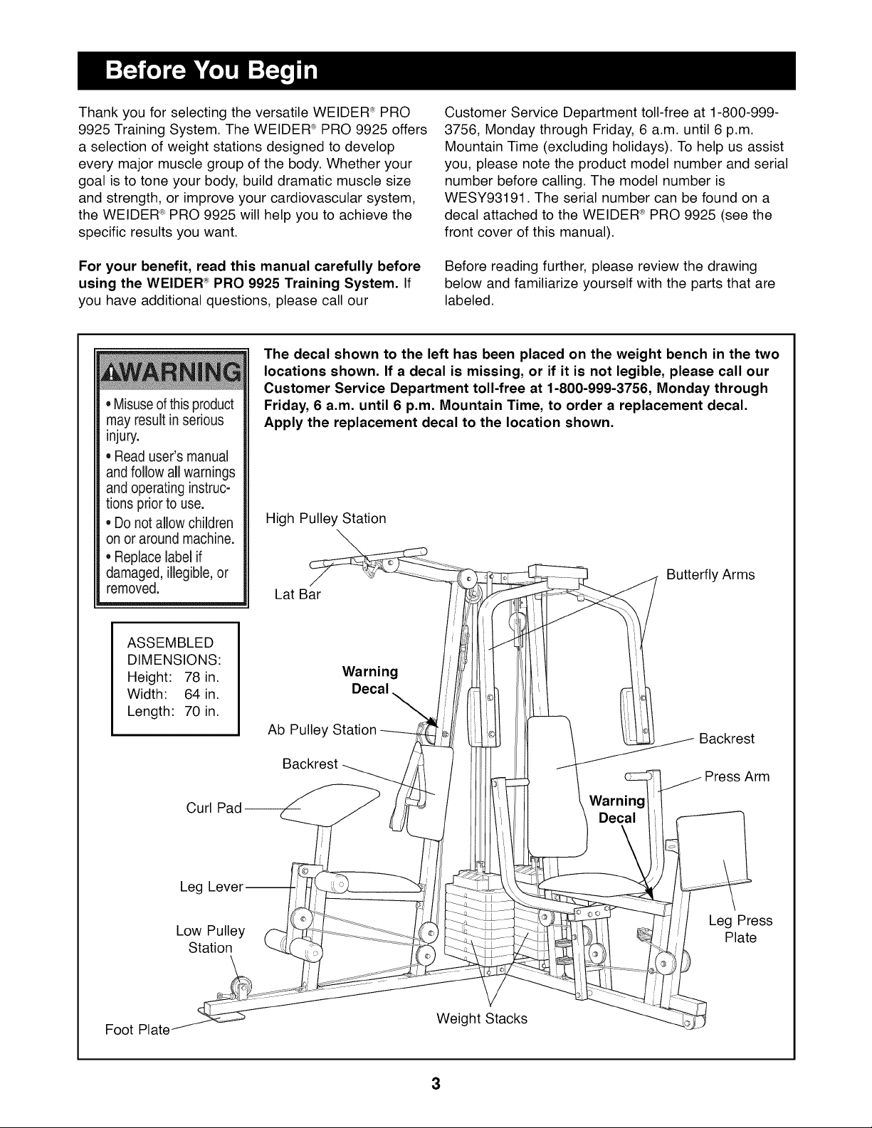
ASSEMBLED
DIMENSIONS:
Height: 78 in.
Width: 64 in.
Length: 70 in.
Friday, 6 a.m. until 6 p.m. Mountain Time, to order a replacement decal.
Apply the replacement decal to the location shown.
High Pulley Station
\
Lat Bar
Warning
Decal
\
Ab Pulley
Before reading further, please review the drawing
below and familiarize yourself with the parts that are
labeled.
Butterfly Arms
Backrest
Foot Plate
Curl
Leg
Low Pulley
Station
Backrest
Arm
Warning
Decal
Leg Press
Plate
Weight Stacks
3
Note: This introduction will save you more
time than it takes to read it!
Making Things Easier for Yourself
Everything in this manual is designed to ensure
that the assembly of our products can be complet-
ed successfully by anyone. However, it is impor-
tant to recognize that your new equipment is a
sophisticated product with many small parts. The
assembly process wilt take time--possibly several
hours. Most people find that by setting aside plen-
ty of time, and by deciding to make the task
enjoyable, assembly will go smoothly. You may
want to complete the process over a couple of
evenings.
Giving Yourself a Good Start
Before you begin the assembly process itself, take
the time to complete the steps outlined here.
Clearing the Workspace
Clear a workspace that is large enough to hold all
parts and allow you to walk all the way around the
assembled equipment.
Identifying Parts
To help you identify the small parts used in assem-
bly, we have included a PART IDENTIFICATION
CHART located in the center of this manual. Place
the chart on the floor or work table and use it to
quickly identify different parts as you open the pack-
ages for each step.
Note: Some small parts may have been pre-attached
for shipping. If a part is not in the parts bag, check to
see if it has been pre-attached.
Orienting Parts
As you assemble this product, be sure that all parts
are oriented as shown in the drawings.
Tightening of Parts
Tighten all parts as you assemble them, unless
instructed to do otherwise.
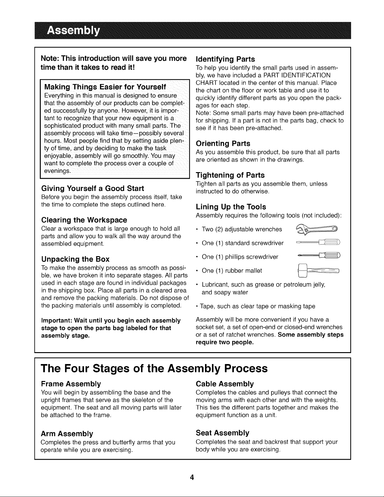
Lining Up the Tools
Assembly requires the following tools (not included):
• Two (2) adjustable wrenches
• One (1) standard screwdriver
Unpacking the Box
To make the assembly process as smooth as possi-
ble, we have broken it into separate stages. All parts
used in each stage are found in individual packages
in the shipping box. Place all parts in a cleared area
and remove the packing materials. Do not dispose of
the packing materials until assembly is completed.
Important: Wait until you begin each assembly
stage to open the parts bag labeled for that
assembly stage.
• One (1) phillips screwdriver
• One (1) rubber mallet
• Lubricant, such as grease or petroleum jelly,
and soapy water
• Tape, such as clear tape or masking tape
Assembly will be more convenient if you have a
socket set, a set of open-end or closed-end wrenches
or a set of ratchet wrenches. Some assembly steps
require two people.
The Four Stages of the Assembly Process
Frame Assembly
You will begin by assembling the base and the
upright frames that serve as the skeleton of the
equipment. The seat and all moving parts will later
be attached to the frame.
Arm Assembly
Completes the press and butterfly arms that you
operate while you are exercising.
Cable Assembly
Completes the cables and pulleys that connect the
moving arms with each other and with the weights.
This ties the different parts together and makes the
equipment function as a unit.
Seat Assembly
Completes the seat and backrest that support your
body while you are exercising.
4
FRAM EASSEM BLY
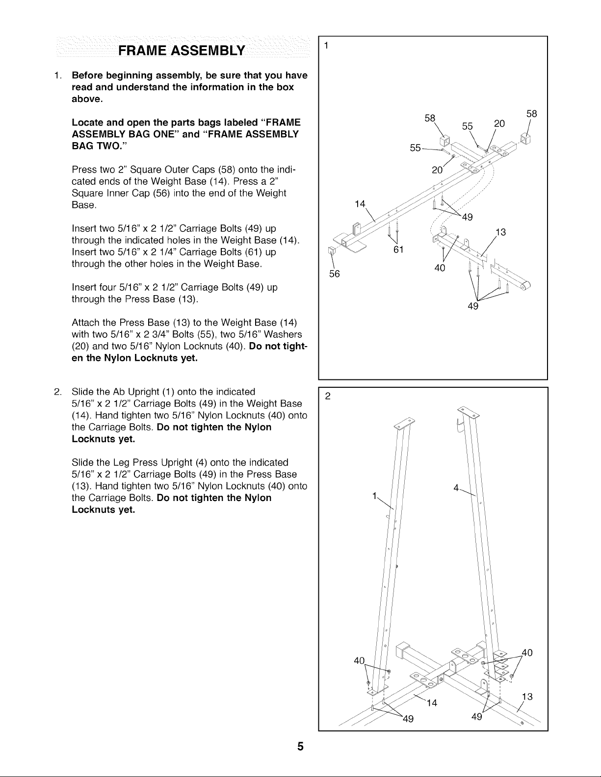
1. Before beginning assembly, be sure that you have
read and understand the information in the box
above.
Locate and open the parts bags labeled "FRAME
ASSEMBLY BAG ONE" and "FRAME ASSEMBLY
BAG TWO."
Press two 2" Square Outer Caps (58) onto the indi-
cated ends of the Weight Base (14). Press a 2"
Square Inner Cap (56) into the end of the Weight
Base.
14
58
55
20
58
\
Insert two 5/16" x 2 1/2" Carriage Bolts (49) up
through the indicated holes in the Weight Base (14).
Insert two 5/16" x 2 1/4" Carriage Bolts (61) up
through the other holes in the Weight Base.
Insert four 5/16"x 2 1/2" Carriage Bolts (49) up
through the Press Base (13).
Attach the Press Base (13) to the Weight Base (14)
with two 5/16" x 2 3/4" Bolts (55), two 5/16" Washers
(20) and two 5/16" Nylon Locknuts (40). Do not tight-
en the Nylon Locknuts yet.
,
Slide the Ab Upright (1) onto the indicated
5/16" x 2 1/2" Carriage Bolts (49) in the Weight Base
(14). Hand tighten two 5/16" Nylon Locknuts (40) onto
the Carriage Bolts. Do not tighten the Nylon
Locknuts yet.
Slide the Leg Press Upright (4) onto the indicated
5/16" x 2 1/2" Carriage Bolts (49) in the Press Base
(13). Hand tighten two 5/16" Nylon Locknuts (40) onto
the Carriage Bolts. Do not tighten the Nylon
Locknuts yet.
56
13
40
49
13
49
5
,
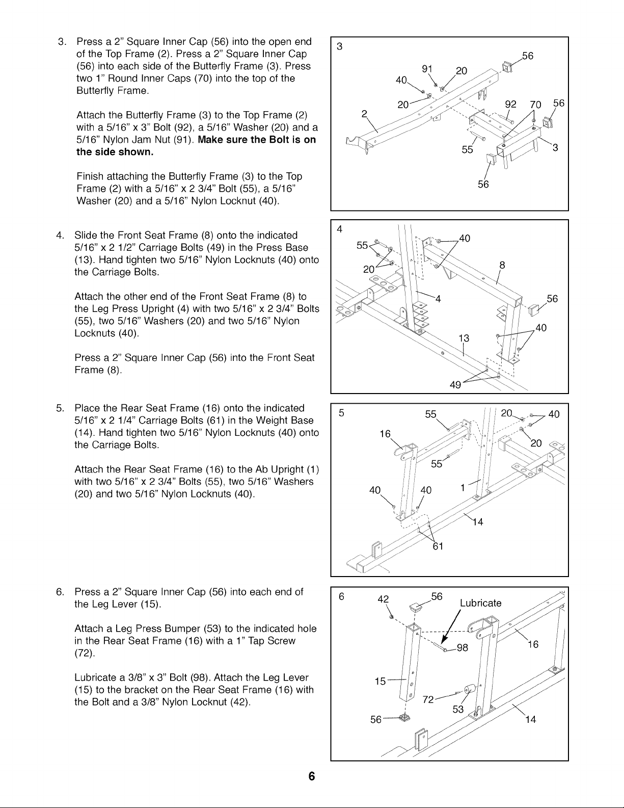
Press a 2" Square Inner Cap (56) into the open end
of the Top Frame (2). Press a 2" Square Inner Cap
(56) into each side of the Butterfly Frame (3). Press
two 1" Round Inner Caps (70) into the top of the
Butterfly Frame.
Attach the Butterfly Frame (3) to the Top Frame (2)
with a 5/16" x 3" Bolt (92), a 5/16" Washer (20) and a
5/16" Nylon Jam Nut (91). Make sure the Bolt is on
the side shown.
2O
92 70
,6
2
55
Finish attaching the Butterfly Frame (3) to the Top
Frame (2) with a 5/16" x 2 3/4" Bolt (55), a 5/16"
Washer (20) and a 5/16" Nylon Locknut (40).
,
Slide the Front Seat Frame (8) onto the indicated
5/16" x 2 1/2" Carriage Bolts (49) in the Press Base
(13). Hand tighten two 5/16" Nylon Locknuts (40) onto
the Carriage Bolts.
Attach the other end of the Front Seat Frame (8) to
the Leg Press Upright (4) with two 5/16" x 2 3/4" Bolts
(55), two 5/16" Washers (20) and two 5/16" Nylon
Locknuts (40).
Press a 2" Square Inner Cap (56) into the Front Seat
Frame (8).
,
Place the Rear Seat Frame (16) onto the indicated
5/16" x 2 1/4" Carriage Bolts (61) in the Weight Base
(14). Hand tighten two 5/16" Nylon Locknuts (40) onto
the Carriage Bolts.
Attach the Rear Seat Frame (16) to the Ab Upright (1)
with two 5/16" x 2 3/4" Bolts (55), two 5/16" Washers
(20) and two 5/16" Nylon Locknuts (40).
4O
16
55
56
56
\
4O
,
Press a 2" Square Inner Cap (56) into each end of
the Leg Lever (15).
Attach a Leg Press Bumper (53) to the indicated hole
in the Rear Seat Frame (16) with a 1" Tap Screw
(72).
Lubricate a 3/8" x 3" Bolt (98). Attach the Leg Lever
(15) to the bracket on the Rear Seat Frame (16) with
the Bolt and a 3/8" Nylon Locknut (42).
61
%
42 56
Lubricate
16
14
6
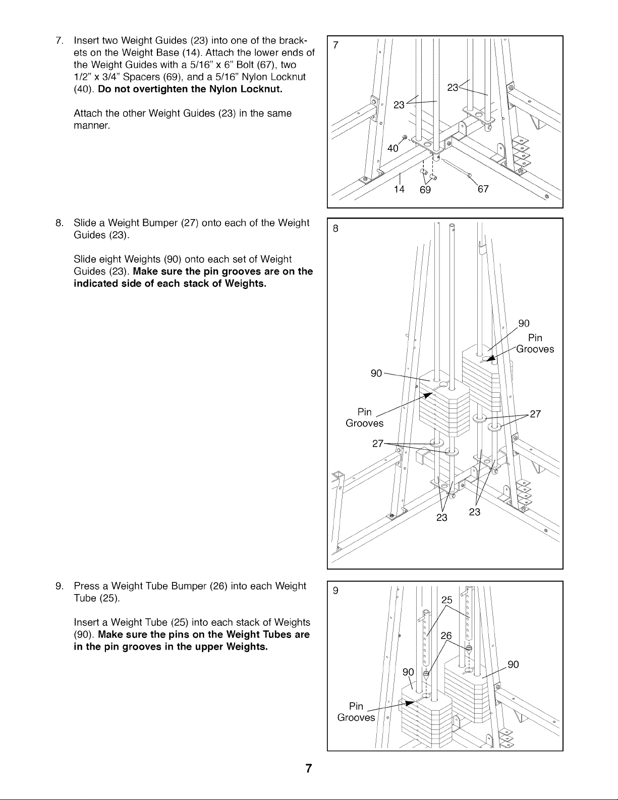
Insert two Weight Guides (23) into one of the brack-
ets on the Weight Base (14). Attach the lower ends of
the Weight Guides with a 5/16" x 6" Bolt (67), two
1/2" x 3/4" Spacers (69), and a 5/16" Nylon Locknut
(40). Do not overtighten the Nylon Locknut.
Attach the other Weight Guides (23) in the same
manner.
,
Slide a Weight Bumper (27) onto each of the Weight
Guides (23).
Slide eight Weights (90) onto each set of Weight
Guides (23). Make sure the pin grooves are on the
indicated side of each stack of Weights.
14
69
8
90
Pin
,
Press a Weight Tube Bumper (26) into each Weight
Tube (25).
Insert a Weight Tube (25) into each stack of Weights
(90). Make sure the pins on the Weight Tubes are
in the pin grooves in the upper Weights.
Grooves
9
Pin
90
23
23
90
Pin
Grooves
7
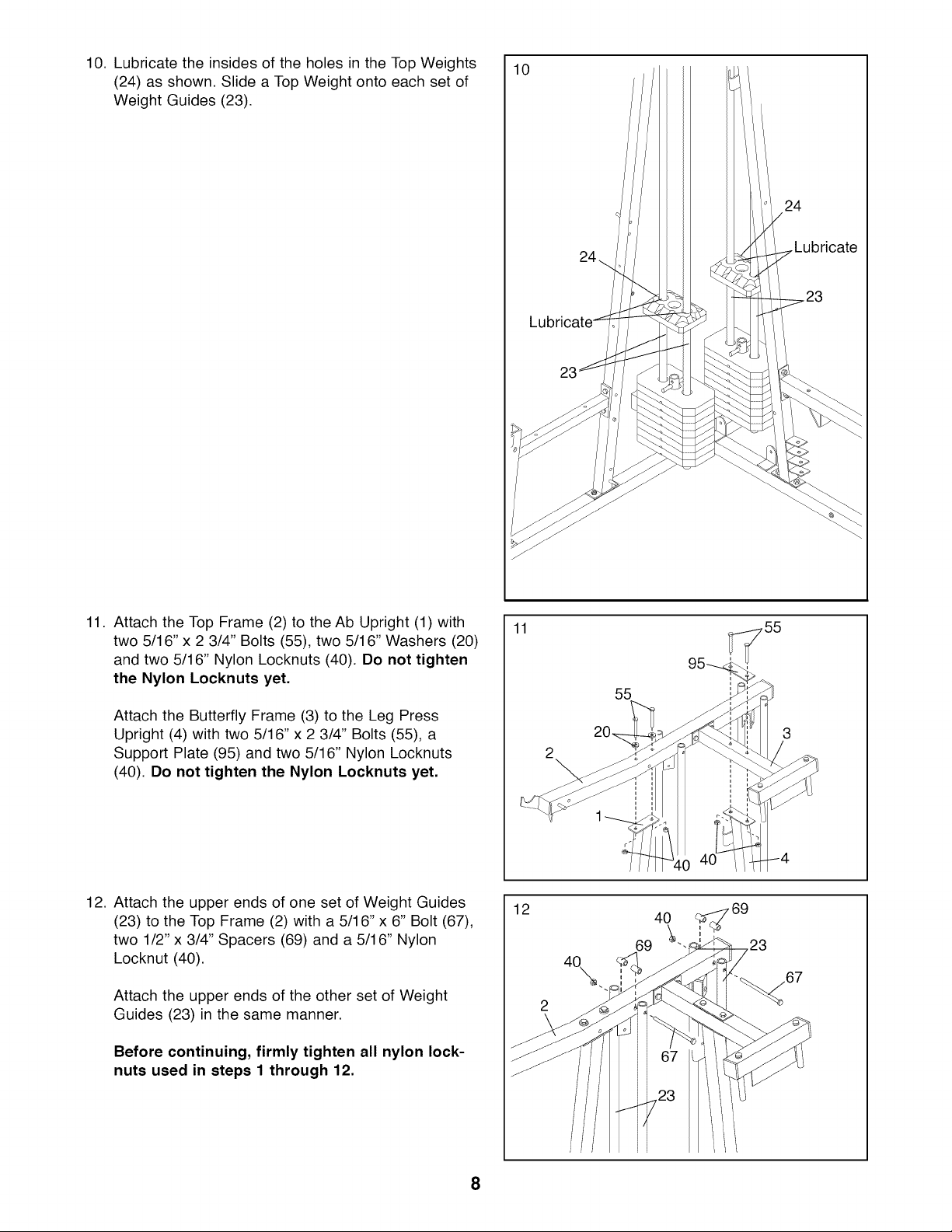
10. Lubricate the insides of the holes in the Top Weights
(24) as shown. Slide a Top Weight onto each set of
Weight Guides (23).
10
24
11.
Attach the Top Frame (2) to the Ab Upright (1) with
two 5/16" x 2 3/4" Bolts (55), two 5/16" Washers (20)
and two 5/16" Nylon Locknuts (40). Do not tighten
the Nylon Locknuts yet.
Attach the Butterfly Frame (3) to the Leg Press
Upright (4) with two 5/16" x 2 3/4" Bolts (55), a
Support Plate (95) and two 5/16" Nylon Locknuts
(40). Do not tighten the Nylon Locknuts yet.
24\
.Lubricate
23
11
55
2
12. Attach the upper ends of one set of Weight Guides
(23) to the Top Frame (2) with a 5/16" x 6" Bolt (67),
two 1/2" x 3/4" Spacers (69) and a 5/16" Nylon
Locknut (40).
Attach the upper ends of the other set of Weight
Guides (23) in the same manner.
Before continuing, firmly tighten all nylon lock-
nuts used in steps 1 through 12.
12
40
69
,23
67
8
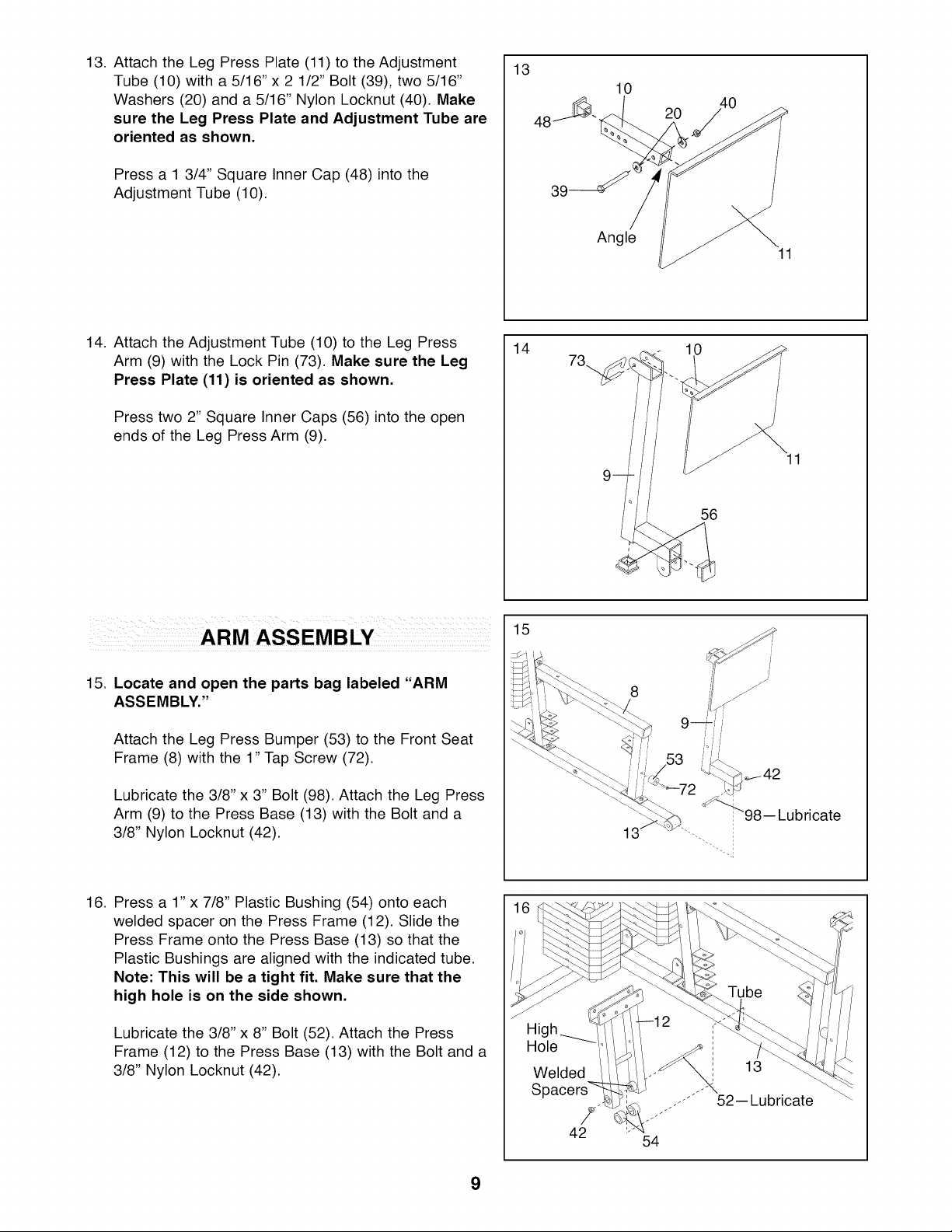
13. Attach the Leg Press Plate (11) to the Adjustment
Tube (10) with a 5/16" x 2 1/2" Bolt (39), two 5/16"
Washers (20) and a 5/16" Nylon Locknut (40). Make
sure the Leg Press Plate and Adjustment Tube are
oriented as shown.
Press a 1 3/4" Square Inner Cap (48) into the
Adjustment Tube (10).
13
10
20
39
14. Attach the Adjustment Tube (10) to the Leg Press
Arm (9) with the Lock Pin (73). Make sure the Leg
Press Plate (11) is oriented as shown.
Press two 2" Square Inner Caps (56) into the open
ends of the Leg Press Arm (9).
15. Locate and open the parts bag labeled "ARM
ASSEMBLY."
14
15
73
Angle
11
10
/
/
/
11
56
Attach the Leg Press Bumper (53) to the Front Seat
Frame (8) with the 1" Tap Screw (72).
Lubricate the 3/8" x 3" Bolt (98). Attach the Leg Press
Arm (9) to the Press Base (13) with the Bolt and a
3/8" Nylon Locknut (42).
16. Press a 1" x 7/8" Plastic Bushing (54) onto each
welded spacer on the Press Frame (12). Slide the
Press Frame onto the Press Base (13) so that the
Plastic Bushings are aligned with the indicated tube.
Note: This will be a tight fit. Make sure that the
high hole is on the side shown.
Lubricate the 3/8" x 8" Bolt (52). Attach the Press
Frame (12) to the Press Base (13) with the Bolt and a
3/8" Nylon Locknut (42).
13
Hole
Welded
13
9
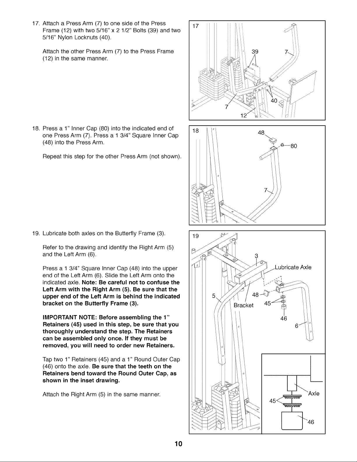
17. Attach a Press Arm (7) to one side of the Press
Frame (12) with two 5/16" x 2 1/2" Bolts (39) and two
5/16" Nylon Locknuts (40).
Attach the other Press Arm (7) to the Press Frame
(12) in the same manner.
18. Press a 1" Inner Cap (80) into the indicated end of
one Press Arm (7). Press a 1 3/4" Square Inner Cap
(48) into the Press Arm.
Repeat this step for the other Press Arm (not shown).
39
19. Lubricate both axles on the Butterfly Frame (3).
Refer to the drawing and identify the Right Arm (5)
and the Left Arm (6).
Press a 1 3/4" Square Inner Cap (48) into the upper
end of the Left Arm (6). Slide the Left Arm onto the
indicated axle, Note: Be careful not to confuse the
Left Arm with the Right Arm (5). Be sure that the
upper end of the Left Arm is behind the indicated
bracket on the Butterfly Frame (3).
IMPORTANT NOTE: Before assembling the 1"
Retainers (45) used in this step, be sure that you
thoroughly understand the step. The Retainers
can be assembled only once. If they must be
removed, you will need to order new Retainers.
Tap two 1" Retainers (45) and a 1" Round Outer Cap
(46) onto the axle, Be sure that the teeth on the
Retainers bend toward the Round Outer Cap, as
shown in the inset drawing.
Attach the Right Arm (5) in the same manner.
19
3
Axle
Bracket 45_
46
I
Lb:x,e
45__
10
 Loading...