

Weider WESY59840 Owner’s Manual

Mode!No.WESY59840
Seria_No.
WritetheseriaUnumberinthe
spaceaboveforfuturereference,
SedaUNumberDecaU(underseat)
Asamanufacturer,wearecom-
mittedto providingcomptete
customersatisfaction.Ifyou
havequestions,or ifthereare
missingordamagedparts,we
will guarantee complete satis-
faction through direct assis-
tance from our factory.
TO AVOID DELAYS, PLEASE
CALL DIRECT TO OUR TOLL-
FREE CUSTOMER NOT LINE.
The trained technicians on our
customer hot tine wil! provide
immediate assistance, free of
charge.
CUSTOMER HOT LINE:
1°877°992°5999
Mon.=Fd., 6 a.m.=6 p.m. MST
Read all precautions and instruc-
tions in this manuat before
using this equipment. Save this
manual for future reference.
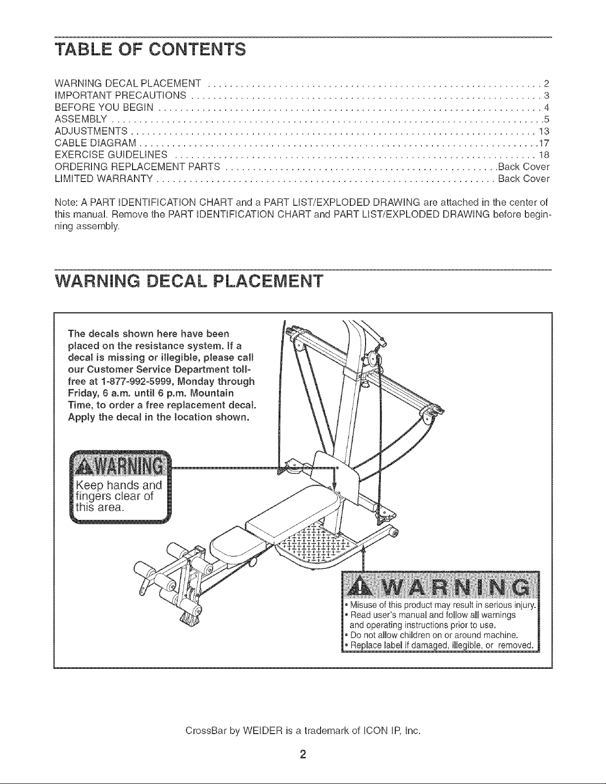
TABLE OF CONTENTS
WARNING DECAL PLACEMENT ............................................................. 2
iMPORTANT PRECAUTIONS ................................................................ 3
BEFORE YOU BEGIN ...................................................................... 4
ASSEMBLY ............................................................................... 5
ADJUSTMENTS .......................................................................... 13
CABLE DIAGRAM ......................................................................... 17
EXERCISE GUiDELiNES .................................................................. 18
ORDERING REPLACEMENT PARTS .................................................. Back Cover
LiMiTED WARRANTY .............................................................. Back Cover
Note: A PART iDENTiFiCATiON CHART and a PART LIST/EXPLODED DRAWING are attached in the center of
this manual. Remove the PART iDENTiFiCATiON CHART and PART LIST/EXPLODED DRAWING before begin-
ning assembly.
WARNING DECAL PLACEMENT
The decals shown here have been
pJaced on the resistance system. If a
decal is missing or iHegibJe, please call
our Customer Service Department toll-
free at 1-877-992-5999, Monday through
Friday, 8 a.m. until 8 p.m. Mountain
Time, to order a free repJacement decal
Apply the decaJ in the location shown.
ieep hands and
ngers clear of
_s area.
®Misuse of this product may result in serious injury.
Read user's manual and follow all warnings
and operating instructions prior to use.
®Do not allow children on or around machine.
* Replace label ifdamaged, illegible, or removed.
CrossBar by WELDER is a trademark of ICON IP, Inc.

iMPORTANT PRECAUTIONS
AWARNING: Toreducethedskofseriousinjury, readthefollowing important precautions
before using the resistance system.
f. Read all instructions in this manual before
using the resistance system. Use the resist- or while standing on the base plate.
ance system only as described in this manu-
aL f 3. The resistance system is designed to be
2_
ff is the re sponsibiHty of the owner to ensure resistance included with a CrossBar by WEI-
that aH users of the resistance system are DER ' Power Pak. Do not use the resistance
adequately informed of all precautions, system with any other type of resistance.
.
The resistance system is intended for home t4.
use onJy. Do not use the resistance system
in any commercial, rental, or institutional set-
ting ....
4. Keep the resistance system indoors, away
(rein moisture and dust. Do not put the t 5.
resistance system in a garage or covered
patio, or near water.
5. Use the resistance system onJy on a (eve)
surface. Cover the floor beneath the resist-
ance system to protect the fJoor.
6. Make sure that aH parts are properly tight-
ened each time the resistance system is
used. Replace any worn parts (mmediateJy.
7. Keep children under 12 and pets away from
the resistance system at aH times.
three positions closest to the upright base,
used with the included resistance, and the
When adding resistance, both ends of the
resistance bars must rest under the two "U'-
channeJs. Add and remove resistance bars
from the "U _ochannels one resistance bar at
a time.
Keep clear of the area around the "U'-chano
neJs while the resistance system is in use.
Do not add or remove resistance bars from
the "U'ochanneJs while the end of the long
cable is pulled out.
16. AJwaye adjust the resistance bar assembly to
the horizontal position and make sure the
fulcrum knob is secure before using the
resistance system.
17. Make sure the rings on the resistance bars
are pushed against the tray before using the
resistance system.
8. Keep hands and feet away from moving
parts.
9. Always wear atHetic shoes for foot protec-
tion while exercising.
16. The top frame is not designed to be used for
puHoup exercises. Do not hang on the top tern is used.
frame.
11. The resistance system is designed to sup-
port a maximum user weight of 306 pounds.
12. Pull on the mowpuJJey cable only while sitting
on the bench or standing on the base plate.
PuH on the high pulley cabJes onJy white sit-
ting on the bench, with the seat in one of the
18. if you purchase the optional lat bar, always
disconnect it from the short cables when
performing an exercise that does not require
it.
19. Make sure the storage knob is in place and
fully tightened each time the resistance sys-
20. Make sure that the cables remain on the puF
leys at all times, if the eabJes bind as you are
exercising, stop immediateJy and make sure
that the cables are on the pulleys. RepJace aH
cables at least every two years.
21. ff you fee( pain or dizziness while exercising,
stop immediateJy and begin cooling down.
kWARNmNG: Beforebeginnin,thisoranyexerciseprogram,consultyourphysician.This
is especially important for persons over the age of 35 or persons with pre-existing health prob)ems.
Read aH instructions before using. (CON assumes no responsibility for personal injury or property
damage sustained by or through the use of this product.
3

BEFORE YOU BEGIN
Thank you for sebcting the innovative CrossBar by
WELDER''_MAX resistance system, The resistance sys-
tem offers a sebction of stations designed to develop
every major muscb group of the body, Whether your
goal is to tone your body, build dramatic muscle size
and strength, or improve your cardiovascular system,
the resistance system will help you to achieve the spe-
cific results you want,
For your benefit, read this manuaJ carefully before
using the resistance system, if you have questions
ASSEMBLED
DiMENSiONS:
Height: 82 in,
Width: 66in_
Depth: 80 in,
Fulcrum Knob
Upright
after reading this manual, phase call our Customer
Service Department tolPfree at 1°877°992-5999,
Monday through Friday, 6 a,m, until 6 p,m, Mountain
Time (excluding holidays), To help us assist you, please
note the product model number and serial number
before calling, The model number is WESY59840, The
serial number can be found on a decal attached to the
resistance system (see the front cover of this manual),
Before reading further, please review the drawing below
and familiarize yourself with the parts that are labeled,
Top Frame
Lat Tower
High Pulley
Resistance Bars
--"U"oChannel
Storage Knob
Backrest
Curl Pad
Curl Bar
Leg
Low Pulley
Base Hate
Seat
Seat Knob
4

Tighten all parts as you assemble them, unless
instructed to do otherwise.
This manua! iSdesigned to ensure that the resist-
most PeOPb, However, it iSimpo_ant to reanize
that the versatile resistance system has many
parts and that the assembly Process w!Htake
time. Most peopJefind that by setting aside p!enty
d t!me, assembly wi!! go smooth!y:
Before beginning assembly, carefully read the
following information and instructions:
Assembly requires two persons.
Place all parts in a cleared area and remove the
packing materials. Do not dispose of the packing
materials until assembly is completed.
• For help identifying smafl parts, use the PART
IDENTIFICATION CHART, Note: Some small
parts may have been pre-attached for shipping. If
a part is not in the parts bag, check to see if it
has been pre-attached.
As you assemble the resistance system, make
sure all parts are oriented as shown in the draw-
ings.
The inc!uded AHen wrenches and the follow-
ing tools (not included) are required for assem-
bly:
Two adjustable wrenches
One rubber maltet
One standard screwdriver _.;_
One Phillipsscrewdriver _=C_-_D
Lubricant, such as grease or petroleum jelty,
and soapy water.
Assembly wiii be more convenient if you have a
socket set, a set of open-end or closed-end
wrenches, or a set of ratchet wrenches,
Before beginning assembly, make sure that
you have read and understand the informa-
tion in the box above.
Attach two Plastic Feet r53_ and two Large Plastic
Feet/102/to the Base Ill with four M4 x 16mm
Screws (62/.
Attach the Upright _3} Io the Base (11 with two
MIO x 66mm Carriage Bolts (83L two MIO x
72mm Bolts (64/. and four MIO Nylon Locknuts
/76 as shown. Note: This step will be easier to
complete if the Upright and Base are tipped
on their sides.
62
53_I _,
/ / /
/// //1//_
64
_102
L
_62
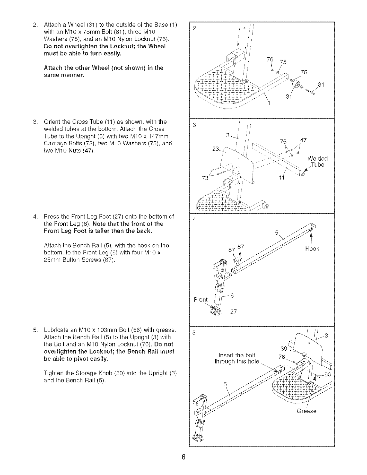
Attacha Wheel(31)totheoutsideoftheBase(1)
withanMIOx78mmBolt(81),threeMIO
Washers(75),andanMIONylonLocknut(76),
Donotovertightenthe Locknut;the Wheel
mustbeableto turn easity.
Attach the other Wheel (not shown} in the
same manner.
Orient the Cross Tube (11) as shown, with the
welded tubes at the bottom, Attach the Cross
Tube to the Upright (3) with two MIO x 147mm
Carriage Bolts (73), two MIO Washers (75), and
two MIO Nuts (47),
Press the Front Leg Foot (27) onto the bottom of
the Front Leg (6), Note that the front of the
Front Leg Foot is taller than the back.
75
81
31
/
75
11
47
Welded
Attach the Bench Rail (5), with the hook on the
bottom, to the Front Leg (6) with four MIO x
25mm Button Screws (87),
Lubricate an MIO x 103mm Bolt (66) with grease,
Attach the Bench Rail (5) to the Upright (3) with
the Bolt and an MIO Nylon Locknut (76), Do not
overtighten the Locknut; the Bench Bait must
be able to pivot easily.
Tighten the Storage Knob (30) into the Upright (3)
and the Bench Rail (5),
87
87
Insert the bolt 76
through this hole
Hook
Grease
6

Attach the Lat Tower (4) to the Upright (3) with
6. 6
four M10 x 25mm Button Screws (87), and four
M10 Lock VVashers (103).
Attach the Name Hate (89) to the Lat Tower (4)
with two M4 x 16mm Screws (62).
Attach two Eyebolts (34) to the Top Frame (10)
with two M8 Washers (59) and two M8 Nylon
Locknuts (65). Do not overtighten the Locknuts;
the Eyebolts must be able to rotate freely.
Attach the Top Frame (10) to the Lat Tower (4)
with two M10 x 65mm Button Screws (70), two
M10 Washers (75), and the Top Frame Cover
(93), Make sure that the Eyebolts (34) are ori-
ented as shown in the inset drawing. If they
are not, turn the Top Frame around and reat-
tach it.
59
65
34
"\..
89
7O
62
75
_3
10
103 87
65
/
Attach the Leg Lever (7) to the Front Leg (6) with
a Long Pin (107) and a Cotter Pin (108),
Side View
10.
34
107
34
6
7
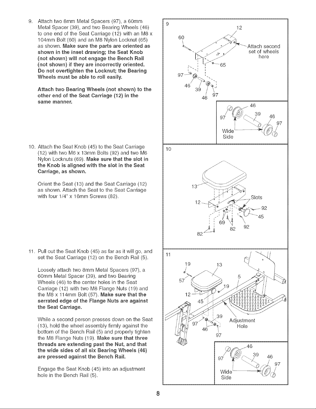
Attach two 8mm Metal Spacers (97), a 60mm
9, 9
Metal Spacer (39), and two Bearing Wheeb (46)
to one end of the Seat Carriage (12) with an M8 x
104mm BoUt(60) and an M8 Nybn Locknut (65)
as shown, Make sure the parts are oriented as
shown in the inset drawing; the Seat Knob
(not shown} will not engage the Bench Rail
(not shown} if they are incorrectly oriented.
Do not overtighten the Locknut; the Bearing
Wheels must be able to roll easily.
Attach two Bearing Wheels (not shown} to the
other end of the Seat Carriage (!2) in the
same manner.
6O
46
39
46
12
second
set of wheels
here
97
Side
10, Attach the Seat Knob (45) to the Seat Carriage
(12) with two M6 x 13mm BoUts(92) and two M6
Nybn Locknuts (69), Make sure that the slot in
the Knob is aligned with the slot in the Seat
Carriage, as shown.
Orient the Seat (13) and the Seat Carriage (12)
as shown, Attach the Seat to the Seat Carriage
with four 1/4" x 16mm Screws (82),
11, Pull out the Seat Knob (45) as far as it will go, and
set the Seat Carriage (12) on the Bench Rail (5),
Loosely attach two 8mm Metal Spacers (97), a
60mm Metal Spacer (39), and two Bearing
Wheels (46) to the center hobs in the Seat
Carriage (12) with two M8 Flange Nuts (19) and
the M8 x 114mm Bolt (57), Make sure that the
serrated edge of the Flange Nuts are against
the Seat Carriage.
While a second person presses down on the Seat
(13), hold the wheel assembly firmly against the
bottom of the Bench Rail (5) and properly tighten
the M8 Flange Nuts (19), Make sure that three
threads are extending past the Nut, and that
the wide sides of aH six Bearing Wheels (46)
are pressed against the Bench Rail.
Engage the Seat Knob (45) into an adjustment
hob in the Bench Rail (5),
10
11
57
19
12
46
Slots
82 92
13
/
5
\
Adjustment
Hob
97
39 46
)7
Side
8
 Loading...