

Weider 831150390 Owner’s Manual
PATENT PENDING
WELDER
Model No. 831.150390
Serial No.
The sedal numbercan be foundinthe
locationshownbelow.Writethe sedal
numberin the space above.
Serial Number Decal
USER,S MANUAL
_- X _" R C i ._ _
F" C) U I P M E N T
I[elli _i..'B n lob _ 1,.1
HELPLINE|
1-800-736-6879
CAUTION
Read all p_utions and,_struc-
tions i_ this manual before
Usi_g;_i_ equipj_ent; S_e this
mmJualJOr_m refe_nce;
8E/ARS
SEARS, ROEBUCK AND CO., HOFFMAN ESTATES, IL 60179
TABLE OF CONTENTS
FULL 90 DAY WARRANTY ............................................................... 2
IMPORTANT PRECAUTIONS ............................................................. 3
BEFORE YOU BEGIN .................................................................. .4
ASSEMBLY ........................................................................... 5
ADJUSTING THE WELDER PRO 635 ....................................................... 12
EXERCISE GUIDELINES ....... _:_................. : ...................................... 14
PART LIST ................. . ......................................................... 18
EXPLODED DRAWING ................................................................. 19
ORDERING REPLACEMENT PARTS ................................................ Back Cover
Note: A PART IDENTIFICATION CHART isattached to the center of this manual. Remove the PART
IDENTIFICATION CHART before beginning assembly.
I FULL 90 DAY WARRANTY I
For 90 days from the date of purchase, if failure occursdue to defect in material or workmanship in this
SEARS WEIGHT BENCH EXERCISER, contact the nearest SEARS Service Center throughout the
United States and SEARS will repair or replace the WEIGHT BENCH EXERCISER, free of charge.
This warranty does not apply when the WEIGHT BENCH EXERCISER is used commercially or for rental
purposes.
This warranty gives you specific legal dghts, and you may also have other dghts which vary from state
to state.
SEARS, ROEBUCK AND CO., DEPT. 817WA, HOFFMAN ESTATES, IL 60179
2
IMPORTANT PRECAUTIONS
WARNING: To reduce the risk of serious Injury, read the following Important precautions before
using the weight bench. ?
,1. Reed all Instructions In this manual before
_,_ usina the weioht bench.
2. Use the,v/eight bench only as described in
.... t!_!s_maiiua I.
r_ Uselthe,_ieight bench only on a levelsurfsce.
CoVer theflo01; beneath the wal_lht bench for
p,)iec.on/ ,
_ Inspectand tighten allparts each time you
iU:se_:the'_ight bench. Replace any worn
_'_rt_; irnl_:ll;_t_lv.
i5,_ Keel3 small children and pets away from the
,_':_ weiaht bench at all times.
_6_;:-Always be:sure there is an equal amount of
Weight on each •side of your barbell (not
included) when V0u are USilia it.
_:_When y0u_areusing the weight carriage, be
sure there is an :equal amount of weight on
_.ac_l_sld;_ _)f the_telaht :tUbe._
9. Keep hands a,d feet away from moving parts.
10. The weight bench doeshot Include weights.
The weight bench IsUeslgned to support a
maximum of 510 pounds, Including the user,
a_weight bar'and welghts._DOnot place _n0re
than 310'_nclsi:_includlng_lght bel_.'a.,_nd_
"welghtsidil the _eightl_sts. Do hat i)lace !::
more than i50 _Unds _nthe weight carl'lage-
use_n_m0rethan 50 pounds for ab crunch-
es.-Do_h_)_pla_re tha_i i50 pounds'oni_
the ieg!ever. _ .......
11; When using the b_ckrest,: make sure that the
"L" pin !s fully Inserted through the adlust-
ment bracket and the bench frame.
12:: If you feelpainbr_dizzlnese at any tlmewhlle
exercising;:stop inlmecllately_and begin Cool-
Ing down. _
_13. It is the responsib Ii_of the owner to ensure
that a I usersof theweightbench are ade,
quate_ _forme_ ,:of:all_ore,_. ,_cauUons.
_:_Always wear athletic shoes for foot protec-
..... tion while exerc sin(:.
_/_RNiNG:Bef0re _lnnln_ this or:any exercise prggram,ic0nSult your physl(_lan, This isespeclally
_mpgrtant for persons over the age of 35 or persons with pre-existing hea!th prob!ems, Read a!!_
_hstru_0nsbefore:US ng,,SE_RS assumes no respons b lity foe _rsona[]njury_ pro_dam ge_
_s_tai_ned by oE_r0ugh the_Use,0fthis producL?
3
BEFORE YOU BEGIN
Thank you for selecting the WEIDEFP PRO 635
Weight Bench. The versatile PRO 635 Weight Bench
is designed to be used with your own weight set (not
included) to develop every major muscle group of the
body. Whether your goal is a shapely figure, dramatic
muscle size and strength, or a healthier cardiovascular
system, the PRO 635 Weight Bench will help you to
achieve the specific resultsyou want.
For your benefit, read this manual carefully before
using the WELDER" PRO 635 Weight Bench. If you
have additional questions, please call ourtoll-free
Weight Rests
HELPLINE at 1-800-736-6879, Monday through
Saturday, 7 a.m. until 7 p.m. Central "13me(excluding
holidays). To help us assist you, please note the prod-
uct model number and serial number before calling.
The model number is 631.150390. The serial number
can be found on a decal attached to the PRO 635
Weight Bench (see the front cover of this manual).
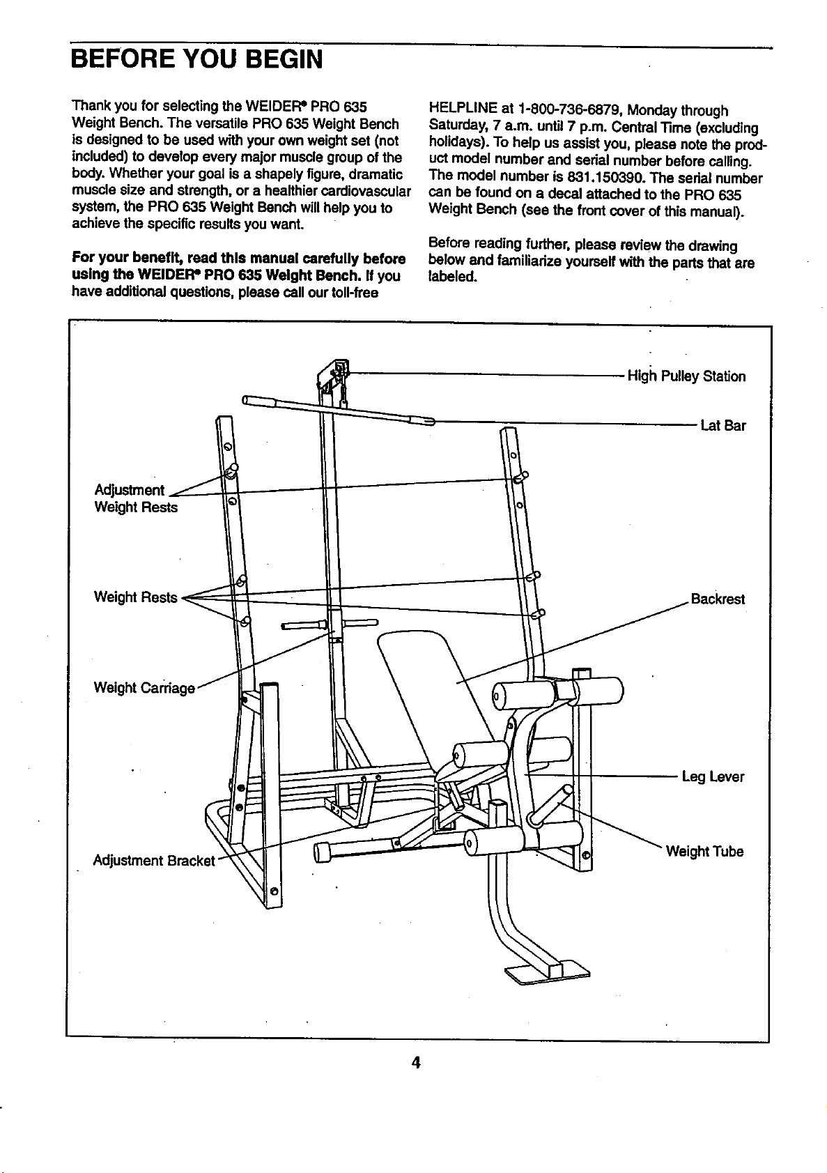
Before reading further, please review the drawing
below and familiarize yourself with the parts that are
labeled.
High Pulley Station
Lat Bar
Weight
Adjustment Bracket
Leg Lever
Weight Tube
4
ASSEMBLY
Before beginning assembly, carefully read the
following Information and Instructions:
• Place all parts in a cleared area and remove _he
packing materials; do not dispose of the packing
materials until assembly is completed.
• Read each assembly step before you begin.
• For help identifying the small pads used in
assembly, use the PART IDENTIRCATION
CHART at the center of this manual. Note: Some
small pads may have been pre-attached for ship-
pingpurposes. If a part is not in the pads bag,
check to see if it has been pre-attached.
• Tighten all parts as you assemble them, unless
instructed to do otherwise.
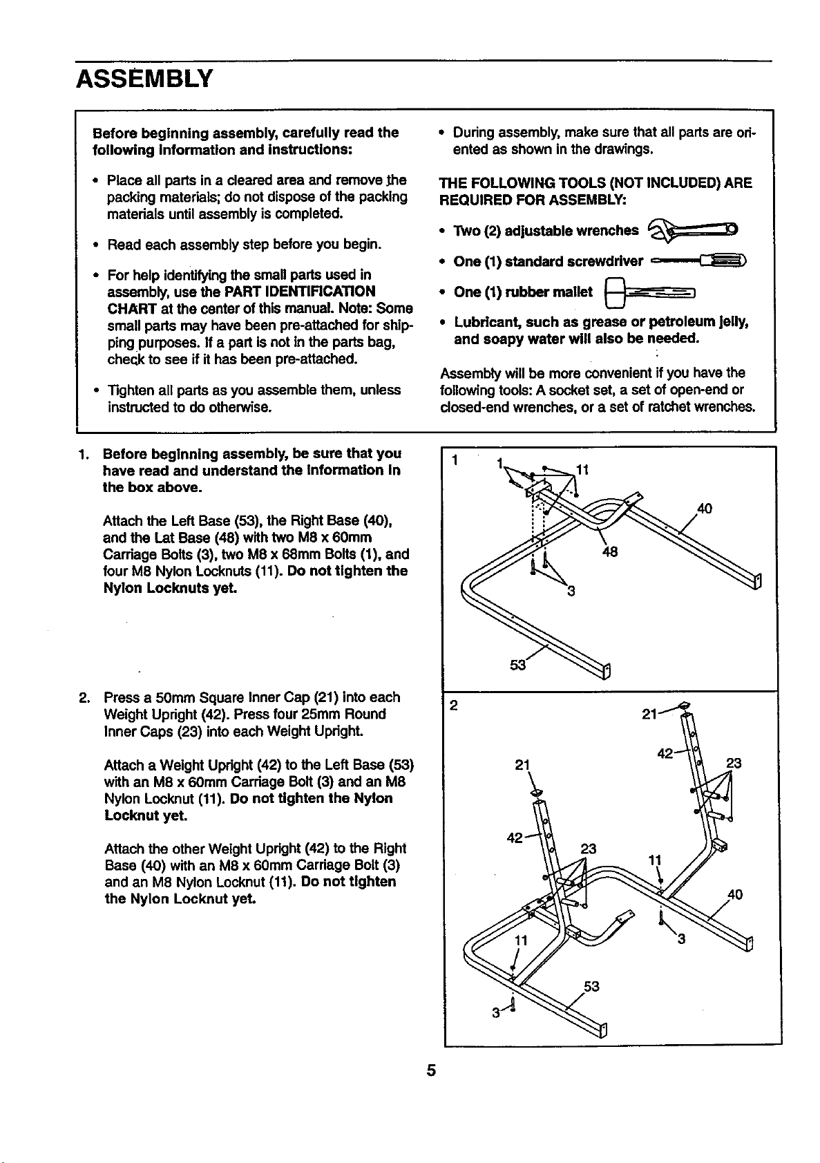
1. Before beginning assembly, be sure that you
have read and understand the Information In
the box above.
Attach the Left Base (53), the Right Base (40),
and the Lat Base (48) with two M8 x 60ram
Carriage Baits (3), two M8 x 68mm Bolts (1), and
four M8 Nylon Locknuts (11). Do not tighten the
Nylon Locknuts yet.
• During assembly, make sure that all parts are ori-
ented as shown in the drawings.
THE FOLLOWING TOOLS (NOT INCLUDED) ARE
REQUIRED FOR ASSEMBLY:
• Two (2) adjustable wrenches
• One (1) standard screwdriver o._
• One (1) rubber mallet
• Lubricant, such as grease or petroleum Jelly,
and soapy water will also be needed.
Assembly will be more convenient if you have the
following tools: A socket set, a set of open-end or
closed-end wrenches, or a set of ratchet wrenches.
11
4O
.
Press a 50mm Square Inner Cap (21) into each
Weight Upright (42). Press four 25mm Round
Inner Caps (23) into each Weight UpdghL
Attach a Weight Upright (42) to the Left Base (53)
with an M8 x 60mm Carriage Bolt (3) and an M8
Nylon Locknut (11). Do not tighten the Nylon
Locknut yet.
Attach the other Weight Upright (42) to the Right
Base (40) with an M8 x 60mm Carriage Bolt (3)
and an M8 Nylon Locknut (11). Do not tighten
the Nylon Locknut yet.
21
23
11
11
53
23
3A
5
.
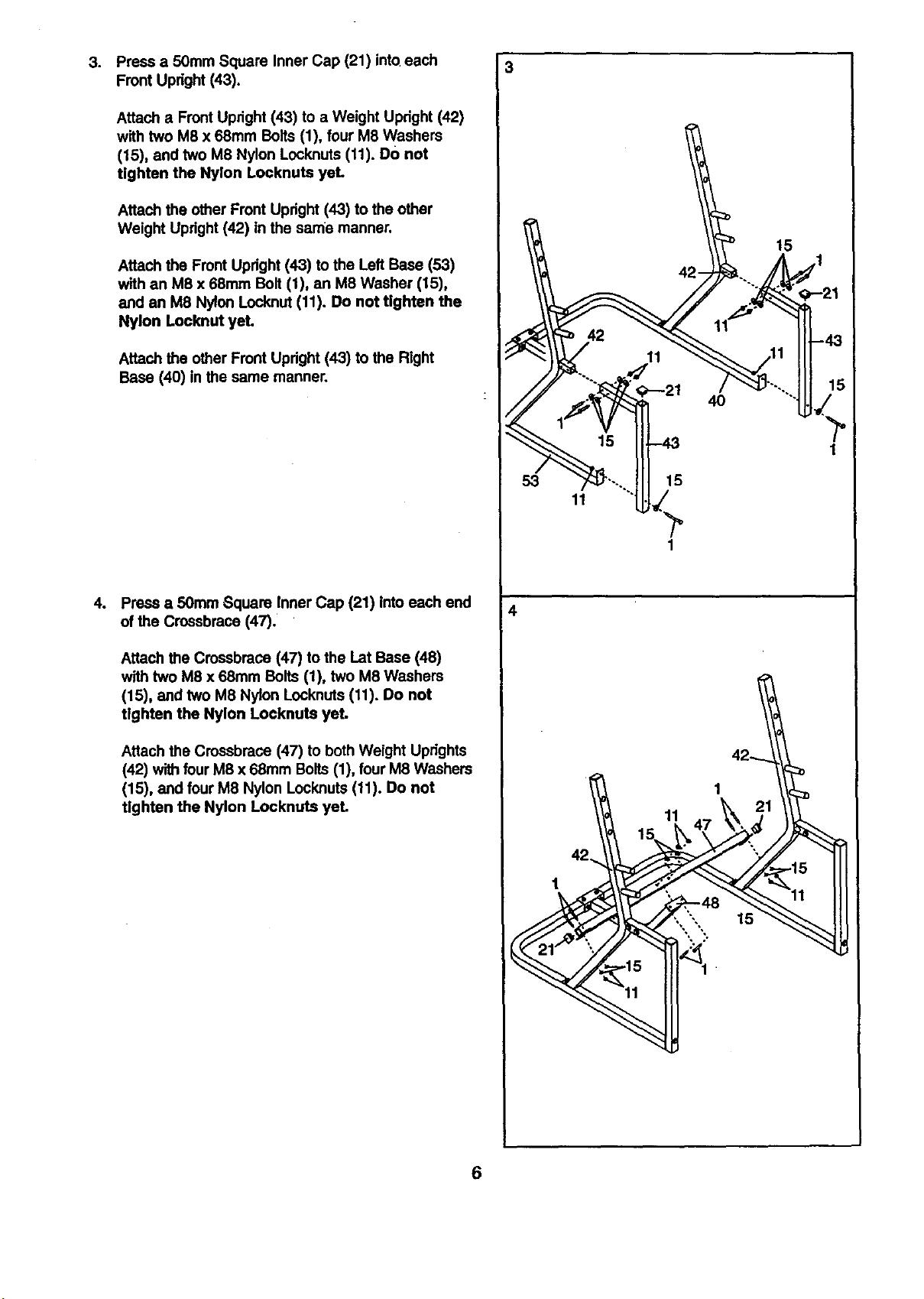
Press a 50mm Square Inner Cap (21) into each
Front Upright (43).
Attach a Front Upright (43) to a Weight Upright (42)
with two M8 x 68mm Bolts (1), four M8 Washers
(15), and two M8 Nylon Locknuts (11). DO not
tighten the Nylon Locknuts yeL
Attach the other Front Upright (43) to the other
Weight Upright (42) in the same manner.
Attach the Front Upright (43) to the Left Base (53)
with an M8 x 68mm Bolt (1), an M8 Washer (15),
and an M8 Nylon Locknut (11). Do not tighten the
Nylon Locknut yet.
Attach the other Front Updght (43) to the Right
Bass (40) in the same manner.
3
15
4O
o
Press a 50mm Square Inner Cap (21) into each end
of the Crossbrace (47).
Attach the Crossbrace (47) to the Lat Base (48)
with two M8 x 68mm Bolts (1), two M8 Washers
(15), and two M8 Nylon Locknuts (11). Do not
tighten the Nylon Locknuts yet.
Attach the Crossbrace (47) to both Weight Uprights
(42) with four M8 x 68ram Bolts (1), four M8 Washers
(15), and four M8 Nylon Locknuts (11). Do not
tighten the Nylon Locknuts yet.
53
15
1
4
1
11
15
6
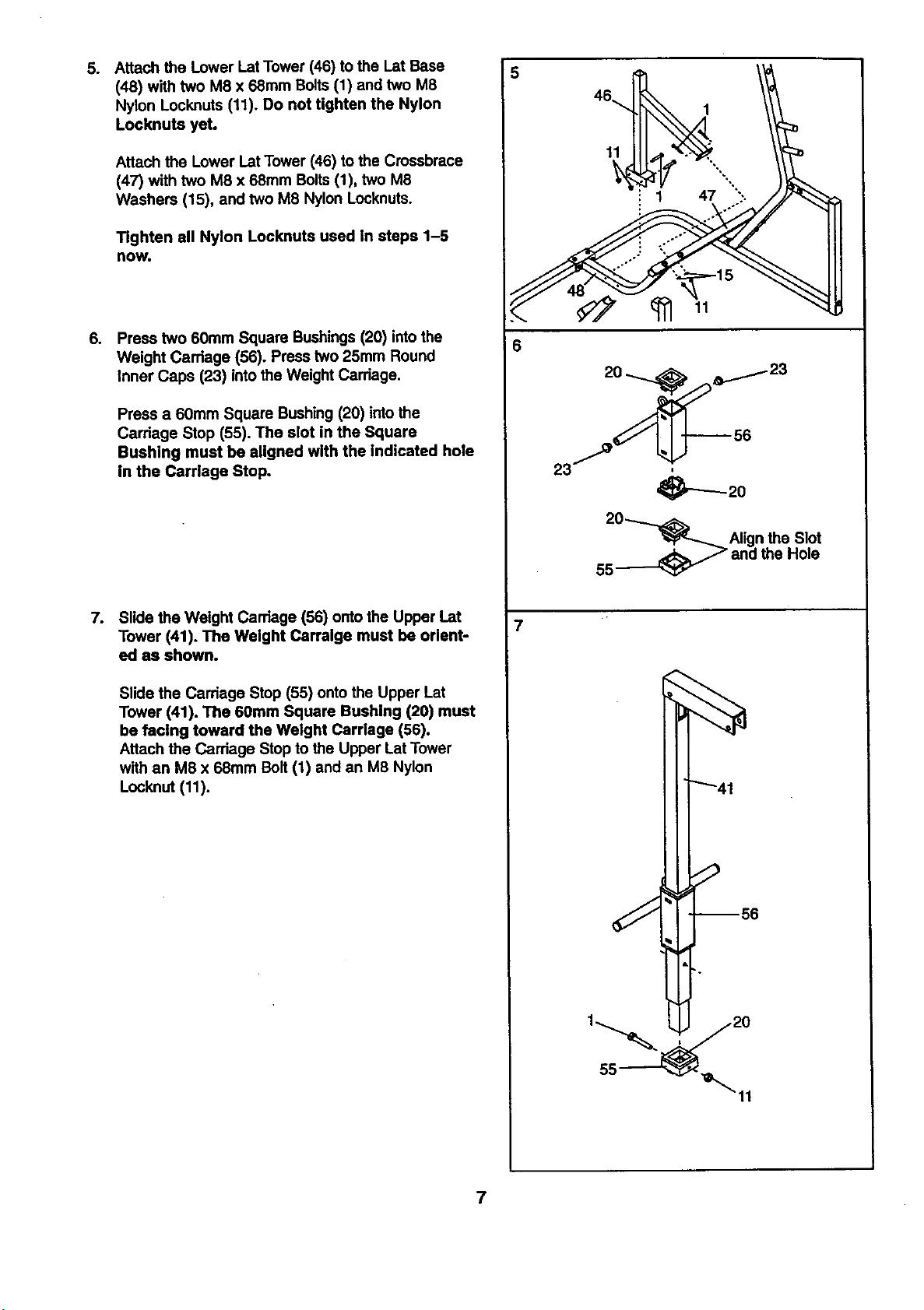
5. Attach the Lower LatTower (46) to the Lat Base
(48) with two M8 x 68ram Bolts (1) and two M8
Nylon Locknuts (11). Do not tighten the Nylon
Locknuts yet.
Attach the Lower Lat Tower (46) to the Crossbrace
(47) with two M8 x 68mm Bolts (1), two M8
Washers (15), and two M8 Nylon Locknuts.
Tighten all Nylon Locknuts used In steps 1-5
now.
o
Press two 60ram Square Bushings (20) into the
Weight Carriage (56). Press two 25mm Round
Inner Caps (23) into the Weight Carriage.
Press a 60mm Square Bushing (20) intothe
Carriage Stop (55). The slot in the Square
Bushing must be aligned with the Indicated hole
in the Carriage Stop.
5
11
6
_'_20
.
Slide the Weight Carriage (56) onto the Upper Lat
Tower (41). The Weight Carralge must be orient-
ed as shown.
Slide the Carriage Stop (55) onto the Upper Lat
Tower (41). The 60mm Square Bushing (20) must
be facing toward the Weight Carriage (56).
Attach the Carriage Stop to the Upper Lat Tower
with an M8 x 68mm Bolt (1) and an M8 Nylon
Lock.nut(11).
20_Align the Slot
55_ and the Hole
7
7
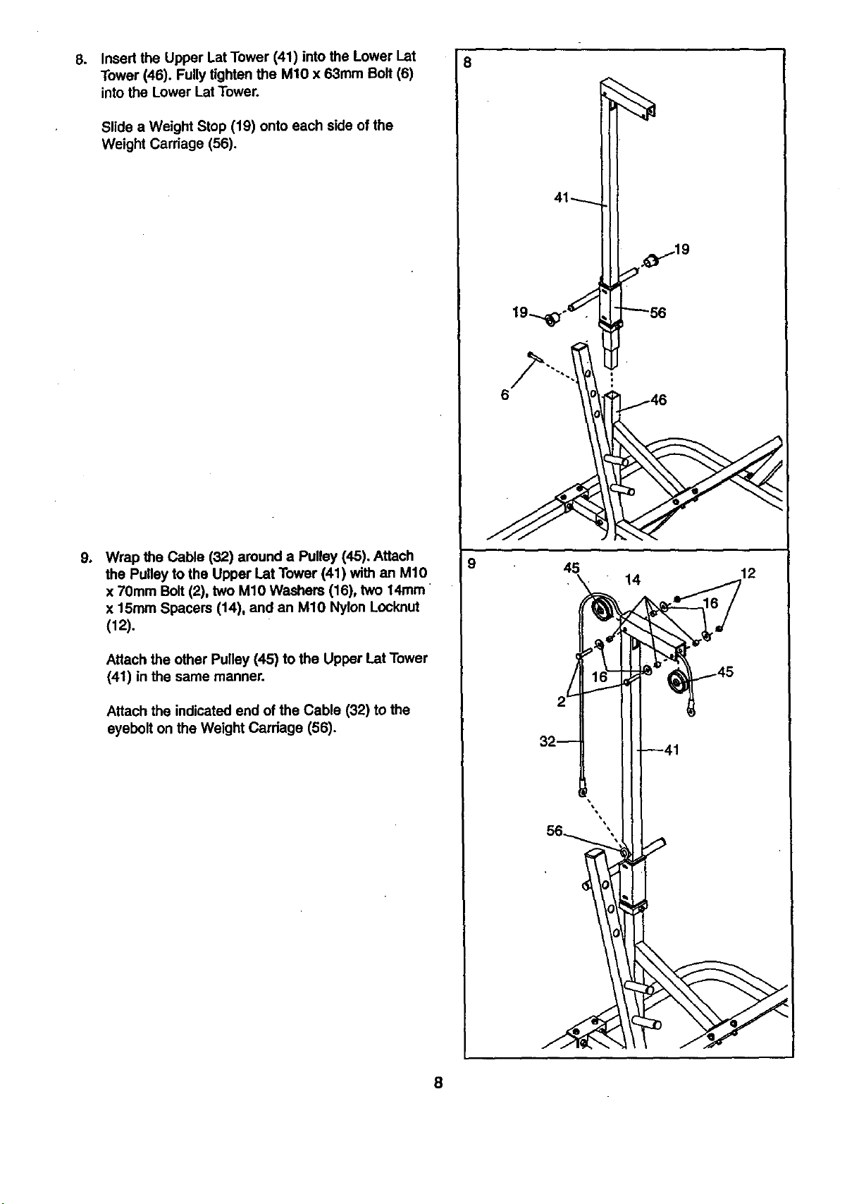
Insert the Upper Lat Tower (41) into the Lower I_at
8. 8
Tower (46). Fully tighten the MIO x 63mm Bolt (6)
intothe Lower Lat Tower.
Slide a Weight Stop (19) onto each side of the
Weight Carriage (56).
6
÷
Wrap the Cable (32) around a Pulley (45). Attach
the Pulley to the Upper Lat Tower (41) with an M10
x 70mm Bolt (2), two M10 Washers (16), two 14mm
x 15ram Spacers (14), and an M10 Nylon Locknut
(12).
Attach the other Pulley (45) to the Upper Lat Tower
(41) in the same manner.
Attach the indicated end of the Cable (32) to the
eyebolt on the Weight Carriage (56).
9
45
12
45
2--
--41
8
 Loading...