

®
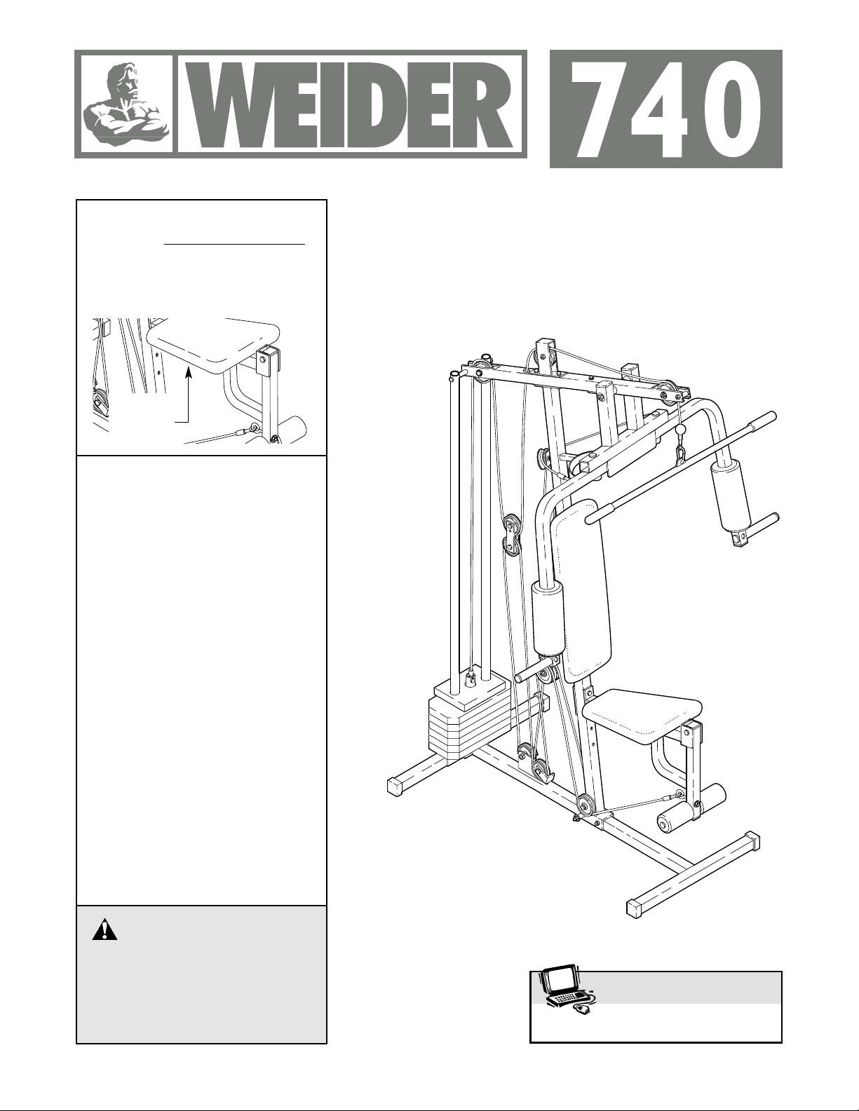
USER’S MANUAL
Model No. WESY74091
Serial No.
The serial number is found in the
location shown below. Write the
serial number in the space above.
CAUTION
Read all precautions and instructions in this manual before using
this equipment. Save this manual for future reference.
Serial
Number
Decal
QUESTIONS?
We are committed to providing
complete customer satisfaction.
If you have questions, or if there
are missing parts, we will guarantee complete satisfaction through
direct assistance from our factory.
TO AVOID UNNECESSARY
DELAYS, PLEASE CALL DIRECT
TO OUR TOLL-FREE CUSTOMER
HOT LINE. The trained technicians on our customer hot line
will provide immediate assistance, free of charge to you.
CUSTOMER HOT LINE:
1-888-936-4266
Mon.–Fri., 8 a.m.–6:30 p.m. EST
(excluding holidays)
Visit our website at
www.weiderfitness.com

2
Limited Warranty . . . . . . . . . . . . . . . . . . . . . . . . . . . . . . . . . . . . . . . . . . . . . . . . . . . . . . . . . . . . . . . . . . . . . . . 2
Important Precautions . . . . . . . . . . . . . . . . . . . . . . . . . . . . . . . . . . . . . . . . . . . . . . . . . . . . . . . . . . . . . . . . . . . 3
Before You Begin . . . . . . . . . . . . . . . . . . . . . . . . . . . . . . . . . . . . . . . . . . . . . . . . . . . . . . . . . . . . . . . . . . . . . . 4
Assembly . . . . . . . . . . . . . . . . . . . . . . . . . . . . . . . . . . . . . . . . . . . . . . . . . . . . . . . . . . . . . . . . . . . . . . . . . . . . 5
Cable Diagrams . . . . . . . . . . . . . . . . . . . . . . . . . . . . . . . . . . . . . . . . . . . . . . . . . . . . . . . . . . . . . . . . . . . . . . 15
Adjustment . . . . . . . . . . . . . . . . . . . . . . . . . . . . . . . . . . . . . . . . . . . . . . . . . . . . . . . . . . . . . . . . . . . . . . . . . . 17
Trouble-shooting and Maintenance . . . . . . . . . . . . . . . . . . . . . . . . . . . . . . . . . . . . . . . . . . . . . . . . . . . . . . . . 18
Weight Resistance Chart . . . . . . . . . . . . . . . . . . . . . . . . . . . . . . . . . . . . . . . . . . . . . . . . . . . . . . . . . . . . . . . . 19
Ordering Replacement Parts . . . . . . . . . . . . . . . . . . . . . . . . . . . . . . . . . . . . . . . . . . . . . . . . . . . . . . Back Cover
Note: A PART LIST/EXPLODED DRAWING and a PART IDENTIFICATION CHART are attached in the centre of
this manual. Remove the centre pages before beginning assembly.
Table of Contents
Limited Warranty
WEIDER is a registered trademark of ICON Health & Fitness, Inc.
ICON OF/DU CANADA INC., (ICON), warrants this product to be free from defects in workmanship and material, under normal use and service conditions, for a period of one (1) year days from the date of purchase.
This warranty extends only to the original purchaser. ICON's obligation under this warranty is limited to
replacing or repairing, at ICON's option, the product at one of its authorized service centers. All products for
which warranty claim is made must be received by ICON at one of its authorized service centers with all
freight and other transportation charges prepaid, accompanied by sufficient proof of purchase. All returns
must be pre-authorized by ICON. This warranty does not extend to any product or damage to a product
caused by or attributable to freight damage, abuse, misuse, improper or abnormal usage or repairs not provided by an ICON authorized service centre, to products used for commercial or rental purposes, or to products used as store display models. No other warranty beyond that specifically set forth above is authorized
by ICON.
ICON is not responsible or liable for indirect, special or consequential damages arising out of or in connection with the use or performance of the product or damages with respect to any economic loss, loss of property, loss of revenues or profits, loss of enjoyment or use, costs of removal, installation or other consequential damages of whatsoever nature. Some provinces do not allow the exclusion or limitation of incidental or
consequential damages. Accordingly, the above limitation may not apply to you. The warranty extended hereunder is in lieu of any and all other warranties and any implied warranties of merchantability or fitness for a
particular purpose is limited in its scope and duration to the terms set forth herein. Some provinces do not
allow limitations on how long an implied warranty lasts. Accordingly, the above limitation may not apply to
you.
The warranty extended hereunder is in lieu of any and all other warranties and any implied warranties of merchantability or fitness for a particular purpose is limited in its scope and duration to the terms set forth herein.
This warranty gives you specific legal rights. You may also have other rights which vary from province to
province or so specified by the retailer of your equipment.
ICON OF/DU CANADA, 900 de l’Industrie, St-Jérôme, QC J7Y 4B8
3
WARNING: Before beginning this or any exercise program, consult your physician. This
is especially important for persons over the age of 35 or persons with pre-existing health problems.
Read all instructions before using. ICON assumes no responsibility for personal injury or property
damage sustained by or through the use of this product.
Important Precautions
1. It is the responsibility of the owner to ensure
that all users of the weight system are adequately informed of all precautions.
2. Read all instructions in this manual and in
the accompanying literature before using the
weight system.
3. If you feel pain or dizziness at any time while
exercising, stop immediately and begin cooling down.
4. Use the weight system only on a level surface. Cover the floor or carpet beneath the
weight system for protection.
5. Inspect and tighten all parts often. Replace
any worn parts immediately.
6. Make sure the cables remain on the pulleys
at all times. If the cables bind while you are
exercising, stop immediately and make sure
the cables are on all of the pulleys.
7. Keep children under the age of 12 and pets
away from the weight system at all times.
8. Keep hands and feet away from moving parts.
9. The weight system is designed to be used by
only one person at a time.
10. Always wear athletic shoes for foot protection when exercising.
11. Never release the press arms/butterfly arms,
leg lever or lat bar while weights are raised.
The weights will fall with great force.
12. Always disconnect the lat bar from the
weight system when performing an exercise
that does not use the lat bar.
13. The weight system is intended for home use
only. Do not use the weight system in a commercial, rental or institutional setting.
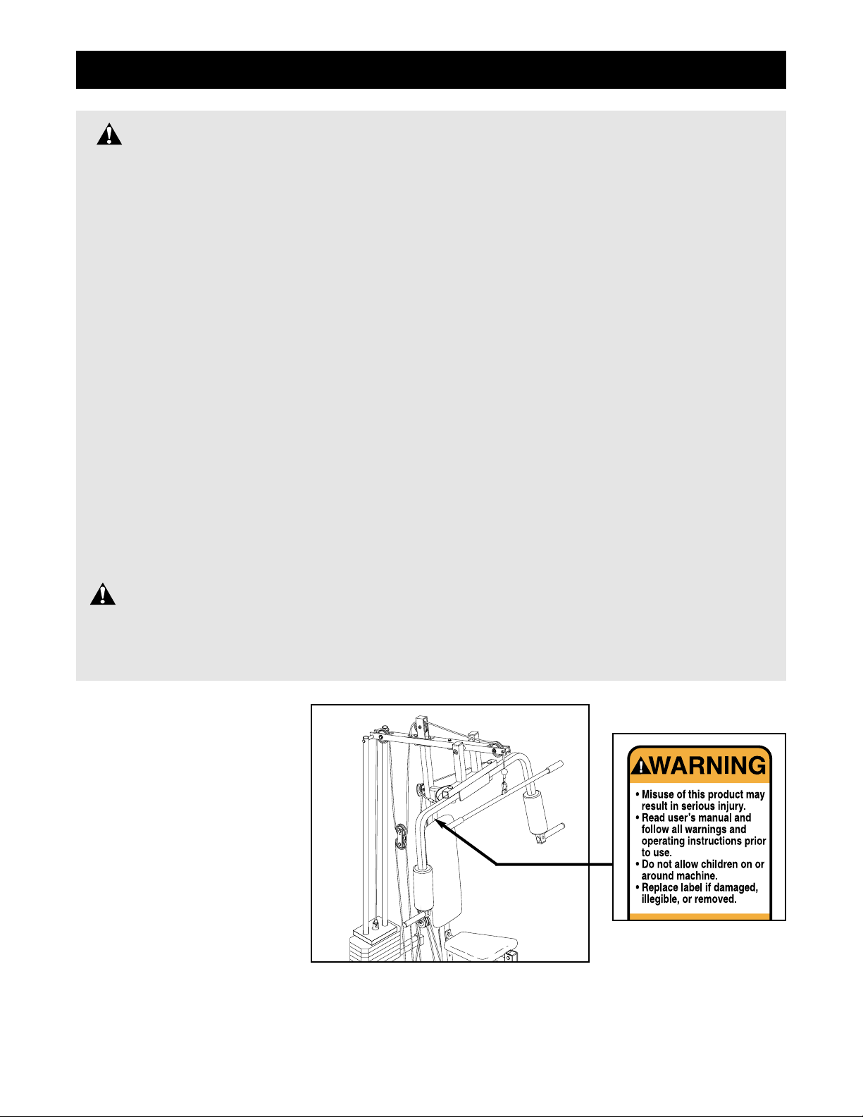
WARNING: To reduce the risk of serious injury, read the following important precau-
tions before using the weight system.
The decal shown at the right
has been attached to the
weight system in the location
shown. If the decal is missing
or illegible, please call our
customer hot line (refer to the
front cover of this manual) to
order a free replacement
decal. Apply the decal in the
location shown.
4
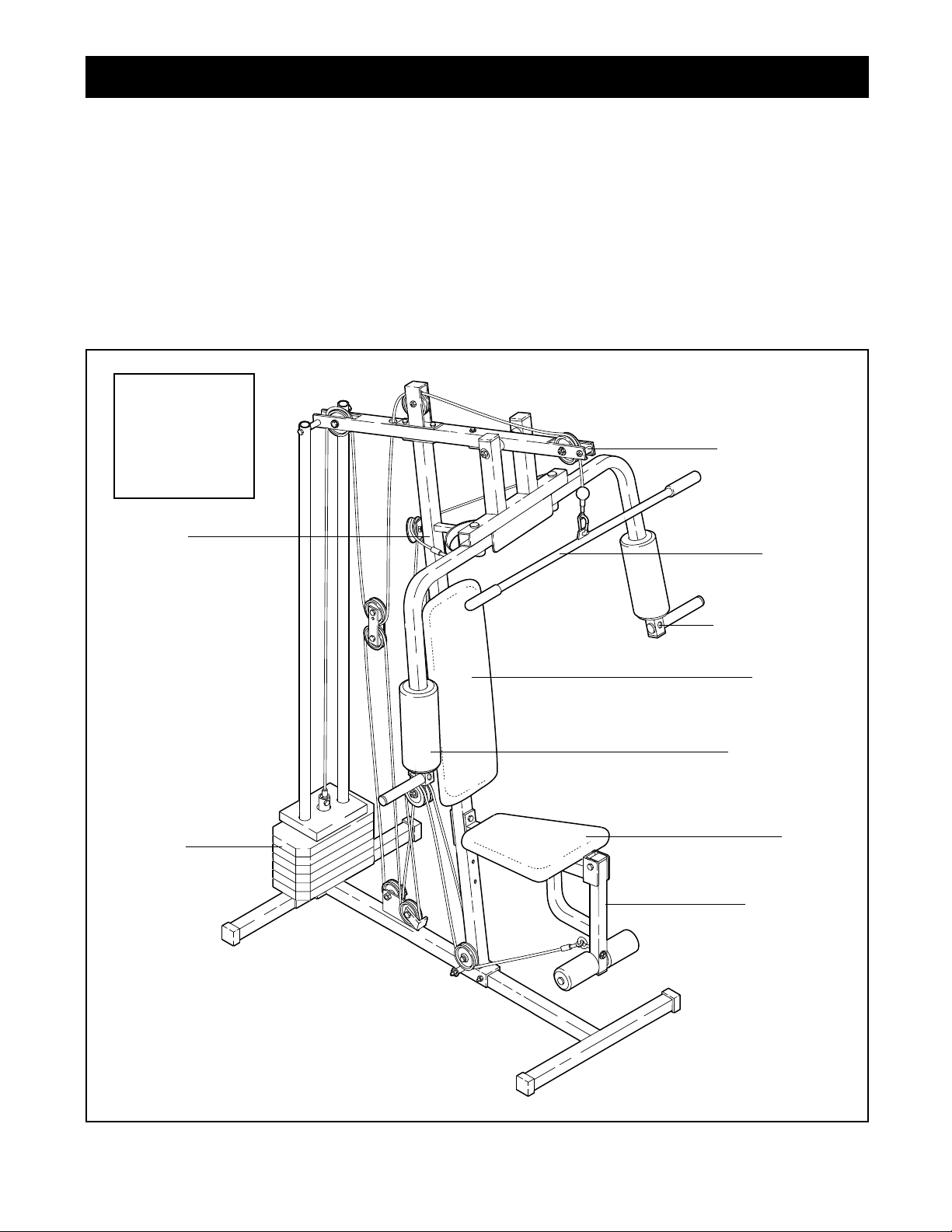
ASSEMBLED
DIMENSIONS:
Height: 75 in.
Width: 31 in.
Length: 44 in.
Weight
Stack
Leg Lever
Butterfly/Press
Arm
Foam Roller
Seat
Backrest
Thank you for selecting the versatile WEIDER®740
weight system. The WEIDER®740 offers a selection of
weight stations designed to develop every major muscle group of the body. Whether your goal is to tone
your body, build dramatic muscle size and strength, or
improve your cardiovascular system, the WEIDER
®
740 will help you to achieve the results you want.
For your benefit, read this manual carefully before
using the weight system. If you have additional
questions, please call our Customer Service
Department toll-free at 1-888-936-4266, Mon.–Fri., 8
a.m.–6:30 p.m. EST (excluding holidays). To help us
assist you, please note the product model number and
serial number before calling. The model number is
WESY74091. The serial number can be found on a
decal attached to the weight system (see the front
cover of this manual).
Please use the drawing below to familiarize yourself with the major parts of the weight system.
Before You Begin
Upright
Lat Bar
Pulley Station
5
Note: This introduction will save you more
time than it takes to read it.
Identifying Parts
To help you identify the small parts used in assembly, we have included a PART IDENTIFICATION
CHART in the centre of this manual. Place the chart
on the floor and use it to easily identify parts. Note:
Some small parts may have been pre-attached for
shipping. If a part is not in the parts bag, check to
see if it has been pre-attached.
Orienting Parts
As you assemble this product, be sure that all parts
are oriented as shown in the drawings.
Tightening Parts
Tighten all parts as you assemble them, unless
instructed to do otherwise.
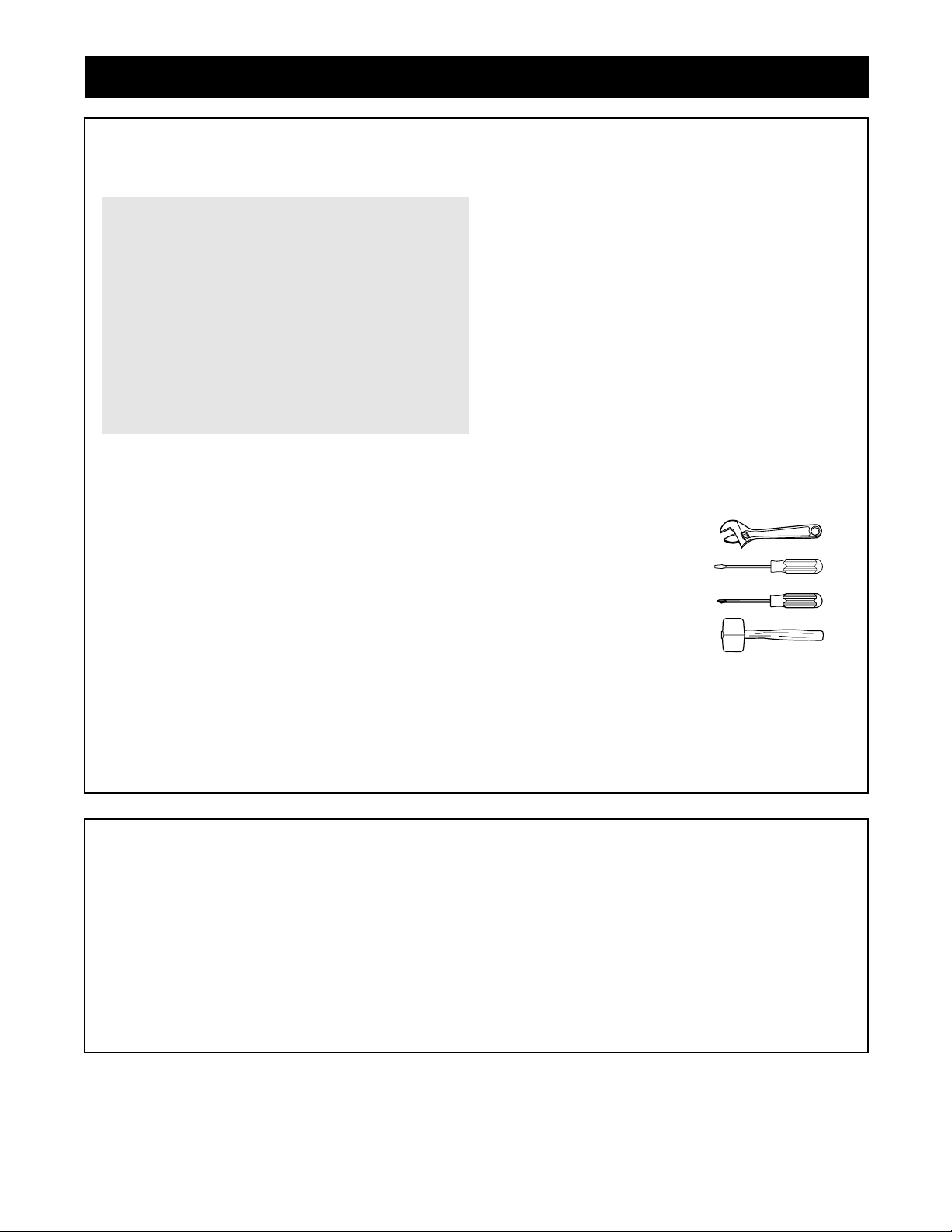
Tools Required
Assembly requires the following tools (not included):
• Two (2) adjustable wrenches
• One (1) standard screwdriver
• One (1) phillips screwdriver
• One (1) rubber mallet
• Lubricant, such as grease or petroleum jelly,
and soapy water
Assembly will be more convenient if you have a
socket set, a set of open-end or closed-end wrenches
or a set of ratchet wrenches.
Clearing a Workspace
Clear a workspace that is large enough to hold all
parts and allow you to walk all the way around the
assembled weight system.
Unpacking the Box
To make the assembly process as smooth as possible, we have divided it into separate stages. All parts
used in each stage are found in individual packages
in the shipping box. Place all parts in a cleared area
and remove the packing materials. Do not dispose of
the packing materials until assembly is completed.
Important: Wait until you begin each assembly
stage to open the parts bag labeled for that
stage.
Assembly
Making Things Easier for Yourself
This manual is designed to ensure that the
weight system can be assembled successfully
by anyone. However, it is important to recognize
that the weight system has many parts and that
the assembly process will require several hours.
Most people find that by setting aside plenty of
time, and by deciding to make the task enjoyable, assembly will go smoothly. You may want
to complete the process over a couple of
evenings.
The Three Stages of the Assembly Process
Frame Assembly
You will begin by assembling the base and the
upright frames that serve as the skeleton of the
equipment.
Arm Assembly
During this stage you will assemble the press/butterfly arms.
Cable/Seat Assembly
During the final stage, you will attach the cables
and pulleys that connect the arms with each other
and with the weights. The seat and backrest will
also be attached during this stage.
6
Frame Assembly
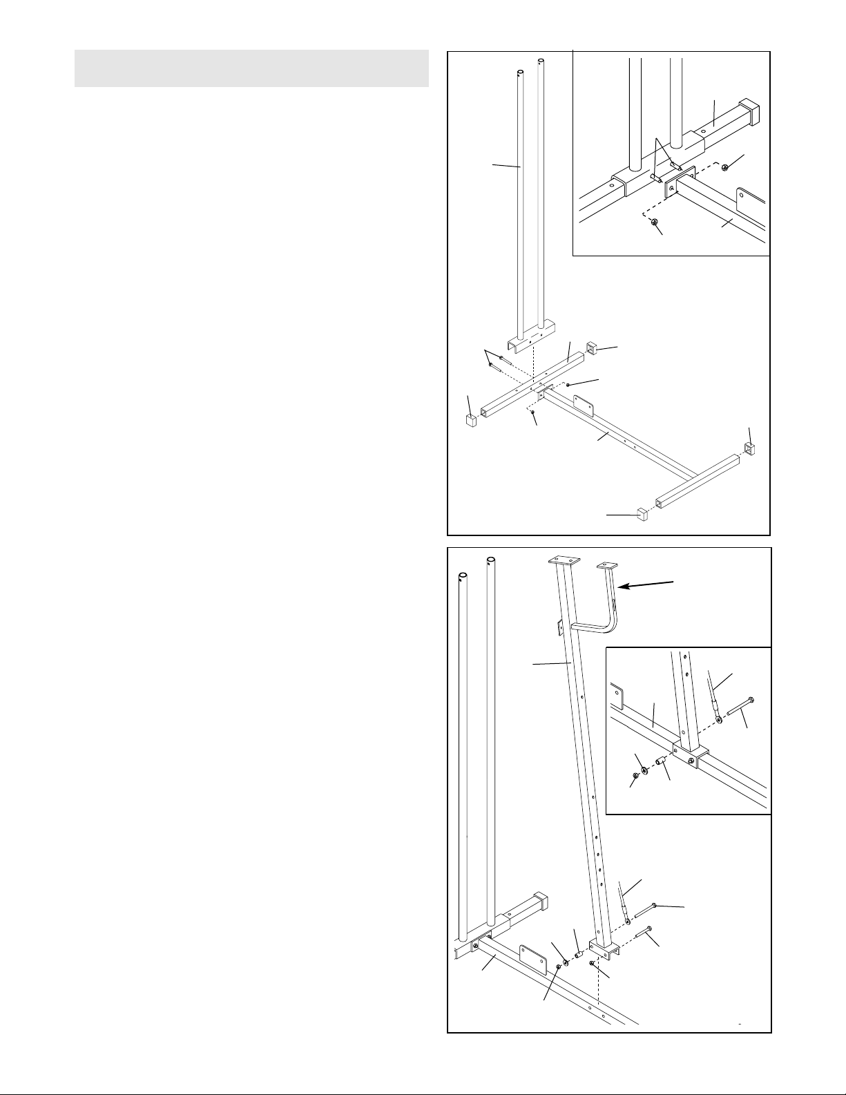
1. Before beginning assembly, make sure you have
read and understood the information on page 5.
Locate and open the parts bag labeled “FRAME
ASSEMBLY.”
Press a 1 1/2” Square Outer Cap (27) onto each end
of the Stabilizer (5) and place it on the floor as
shown.
Press a 1 1/2” Square Outer Cap (27) onto each end
of the Base (4) and place it on the floor as shown.
Place the bracket on the Weight Guide (62) over the
Stabilizer (5). Note: It will be helpful to have a sec-
ond person hold the Weight Guide while performing this step. Line up the holes in the bracket with
the holes in the Stabilizer and insert two 5/16” x
2 1/2” Bolts (14).
See the inset drawing. Slide the bracket on the
Base (4) onto the 5/16” x 2 1/2” Bolts (14) and secure
the Bolts with two 5/16” Nylon Locknuts (3). Do not
tighten the Nylon Locknuts yet.
1
3
4
27
27
27
62
3
27
14
5
2. Place the bracket on the Upright (42) over the Base
(4). CAUTION: Make sure the Upright is oriented
as shown. Note: It will be helpful to have a second person hold the Upright while performing
this step.
Line up the holes in the bracket on the Upright (42)
with the indicated holes in the Base (4). Slide a 5/16”
x 2 1/4” Bolt (1) through the indicated hole and
mount a 5/16” Nylon Locknut (3) onto the Bolt. Do
not tighten the Nylon Locknut yet.
Locate the Long Cable (23). It is approximately 233“
long and it has a closed loop on both ends.
See the inset drawing. Slide a 5/16” x 3 1/4” Bolt
(33) through the closed loop on one end of the Long
Cable (23). Slide the Bolt through indicated hole in
the bracket on the Upright (42) and the Base (4).
Slide a 1 1/2” x 3/4” Spacer (45) and a 5/16” Flat
Washer (8) onto the 5/16” x 3 1/4” Bolt (33). Hand
tighten a 5/16” Nylon Locknut (3) onto the Bolt. Note:
Leave the Nylon Locknut hand tight when you are
asked to tighten the other Locknuts in step 6.
2
33
23
3
45
8
1
42
4
3
Make sure the
bracket is on
this side
3
4
3
14
5
33
23
45
8
4
3
7
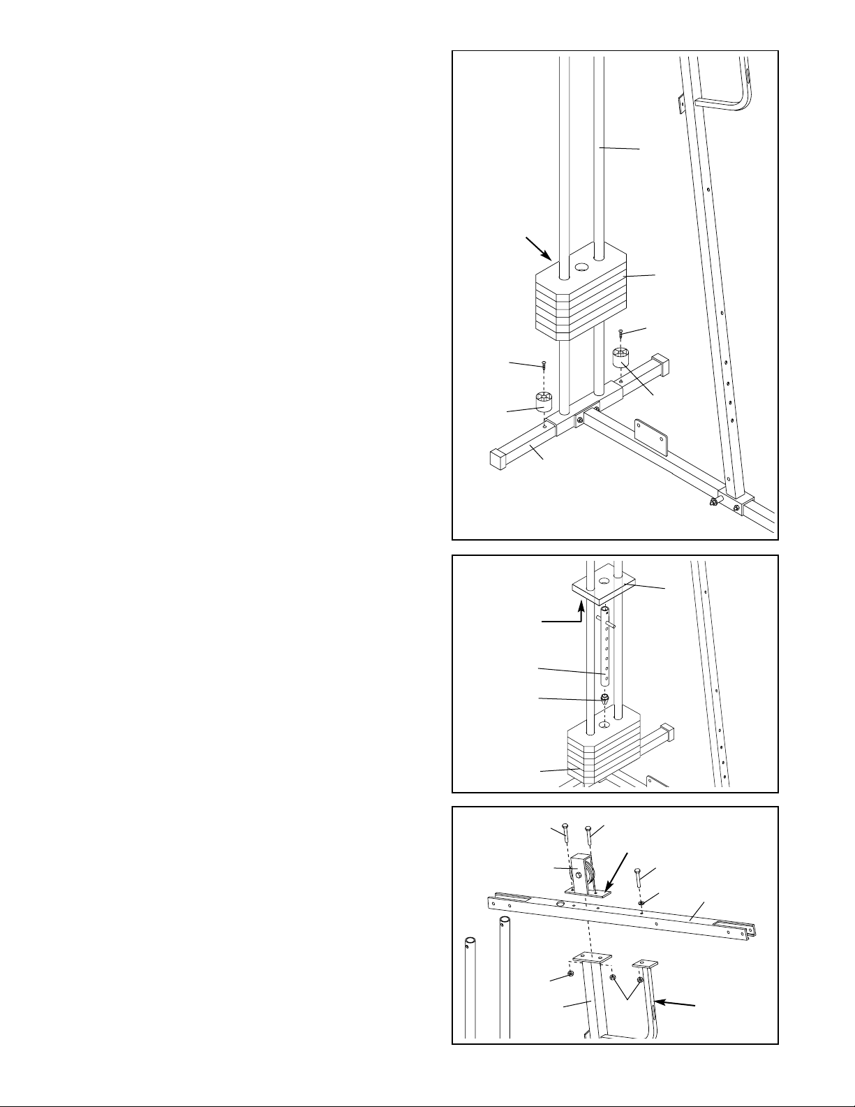
3. Attach the two Weight Bumpers (19) to the Stabilizer
(5) with two #8 x 1” Screws (18).
Slide the six Weights (25) onto the two tubes on the
Weight Guide (62).
Note: Make sure all of the Weights are turned so
the pin grooves are on the same side and that the
grooves are oriented as shown in the drawing.
3
19
19
18
18
5
62
25
Pin
Grooves
4. Press the Weight Tube Bumper (64) into the end of
the Weight Tube (63).
Insert the Weight Tube (63) into the stack of Weights
(25).
Lubricate the insides of the holes in the Top Weight
(67).
With the slot facing down, slide the Top Weight (67)
onto the two tubes on the Weight Guide (62) and set
it on the stack of Weights (25).
4
67
63
25
64
Slot
5. Place the Top Frame (55) on top of the Upright (42)
as shown. Insert a 5/16” x 2 1/4” Bolt (1) with a 5/16”
Flat Washer (8) through the Top Frame and the
bracket on the support frame. Finger tighten a 5/16”
Nylon Locknut (3) onto the Bolt.
Hold the Large Pulley Bracket (40) on the Top Frame
(55). Make sure that the Large Pulley Bracket is
turned as shown. Attach the Large Pulley Bracket
and the Top Frame to the Upright (42) with two 5/16”
x 2 1/4” Bolts (1) and two 5/16” Nylon Locknuts (3).
Do not tighten Nylon Locknuts(3) yet.
5
1
1
3
3
40
55
1
Long end of bracket
must be on this side
8
42
Support
Frame
8
6
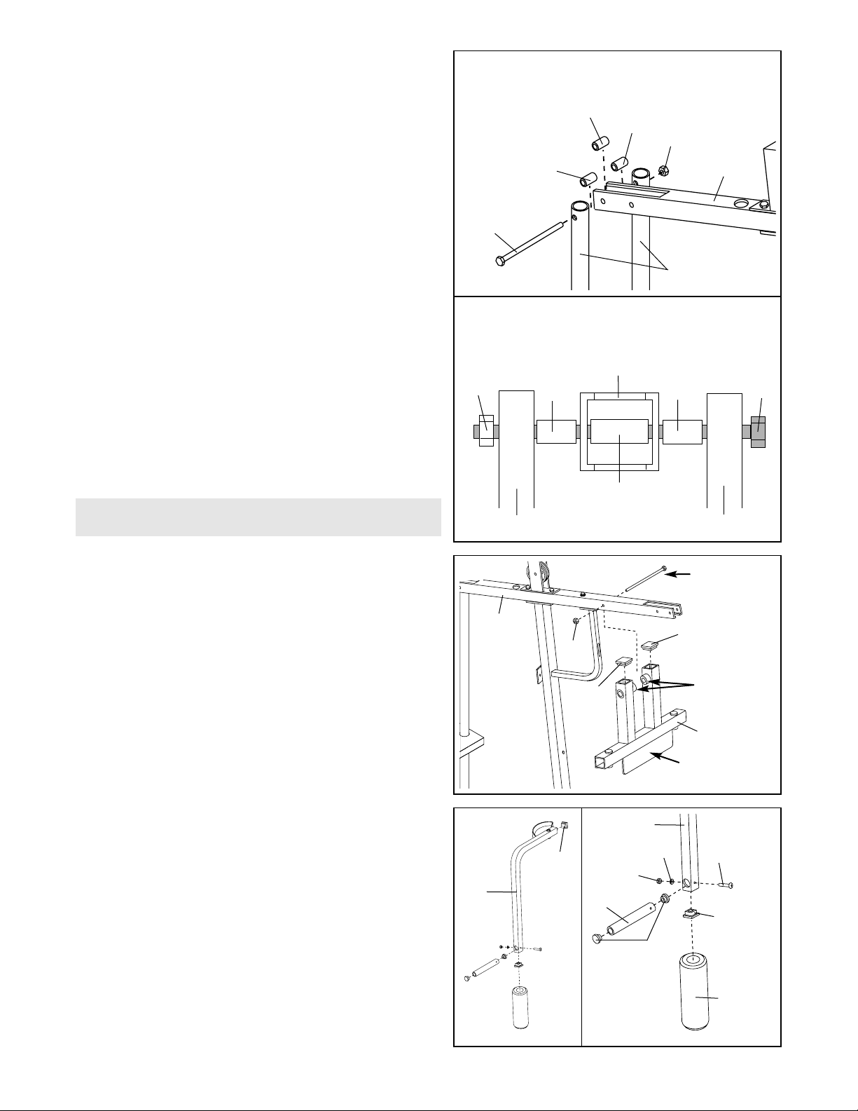
6. Attach the two tubes on the Weight Guide (62) to the
Top Frame (55) in the following manner:
Slide a 5/16” x 6” Bolt (7) through one of the tubes on
the Weight Guide (62) until the tip is barely visible on
the other side. Position a 1/2” x 1” Spacer (51) and
slide the Bolt through it. Then slide the Bolt through
one sidewall of the Top Frame (55).
Position a 1/2” x 1 3/8” Spacer (61) inside the Top
Frame (55) and slide the 5/16” x 6” Bolt (7) through it.
Then slide the Bolt through the other sidewall of the
Top Frame.
Position a 1/2” x 1” Spacer (51) and slide the 5/16” x
6” Bolt (7) through it. Then slide the Bolt through the
other tube on the Weight Guide.
Secure the 5/16” x 6” Bolt (7) with a 5/16” Nylon
Locknut (3) do not tighten at this time.
Tighten all Nylon Locknuts (3) used in steps 1-6.
51
7
Top Frame
(55)
Schematic view from the back
3
61
Weight Guide Tube
51
Weight Guide Tube
7. Locate and open the parts bag labeled “ARM
ASSEMBLY.”
Press a 1 1/2” Square Inner Cap (32) into the open
tubes on the Press Frame (17).
Align the welded spacers on the Press Frame (17)
with the indicated holes in the Top Frame (55).
Lubri c a t e the 3/8 ” x 6” Bolt (16). Attach the Press
Frame to the Top Frame with the Bolt and a 3/8”
Nylon Locknut (21).
Make sure the welded tab on the Press Frame (17)
is oriented as shown.
7
Arm Assembly
16 Lubricate
Welded
Spacers
32
17
21
55
Welded Tab
32
8. Press a 1 3/4” Square inner Cap (77) into each end
of the Right Arm (48).
Wet the lower end of the Right Arm (48) with soapy
water and slide a Foam Roller (71) onto the Arm.
Press a 1” Round Inner Cap (49) into each end of a
Press Handle (46). Attach the Press Handle to the
Right Arm (48) with a 1/4” x 1 3/4” Screw (52), a 1/4”
Flat Washer (10) and a 1/4” Nylon Locknut (2).
Repeat this procedure for the Left Arm (47).
8
77
48
48
2
10
52
77
49
71
46
3
55
62
51
7
61
51
9
9
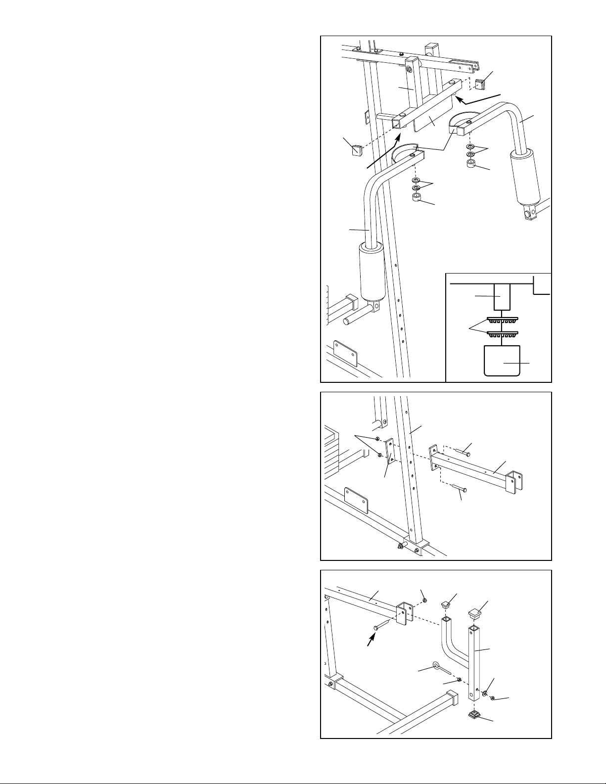
9. Identify the Right Arm (48) and the Left Arm (47) by
imagining yourself sitting on the seat. Note the position of the welded bracket (A) on each Arm. Arm
identification is very important for this step.
Lubricate both axles on the Press Frame (17). Slide
the Right Arm (48) onto the right axle. Note: Be care-
ful not to confuse the Right and Left Arm. Make
sure the upper end of the Right Arm is behind the
indicated bracket (B) on the Press Frame.
Place two 1” Retainer Rings (69) on top of a 1”
Round Cover Cap (70) and tap all three parts onto
the Right Axle with a hammer. Make sure the teeth
on the Retainer Rings bend towards the Cover
Cap, as shown in the inset drawing.
Attach the Left Arm (47) in the same manner.
Press a 1 3/4” Square Inner Cap (77) into each end
of the crossbar on the Press Frame (17).
A
B
48
47
77
69
70
69
70
17
77
Axle
69
70
10. Attach the Seat Frame (36) to the Upright (42) with
two 5/16” x 2 1/2” Bolts (14), the Support Bracket (6)
and two 5/16” Nylon Locknuts (3).
10
6
36
14
14
42
11. Press a 1 1/2” Square Inner Cap (32) into the upper
and lower ends of the Leg Lever (29).
Press a 1” Square Inner Cap (65) into the top of the
support bracket on the Leg Lever (29).
Thread a 3/8” Plain Nut (56) partway onto the 3/8”
Eyebolt (35). Insert the Eyebolt through the indicated
hole in the Leg lever (29) and secure it with a 3/8”
Flat Washer (9) and a 3/8” Nylon Jamnut (22).
Lubricate a 3/8” x 2 1/2” Bolt (60). Attach the Leg
Lever (29) to the bracket on the Seat Frame (36) with
the Bolt and a 3/8” Nylon Jamnut (22).
11
36
35
56
32
60 Lubricate
22
65
32
29
22
9
Lubricate
Lubricate
3
 Loading...