

Page 1
Model No. WEEVBE70500
Serial No.
Write the serial number in the space
above for reference.
Part No. 171701 R1100A Printed in China © 2000 ICON Health & Fitness, Inc.
WEIDER is a registered trademark of ICON Health & Fitness, Inc.
HOW TO ORDER REPLACEMENT PARTS
To order replacement parts, contact the ICON Health & Fitness Ltd. office, or write:
ICON Health & Fitness, Ltd.
Greenwich House
223 North Street
Sheepscar
Leeds LS7 2AA
West Yorkshire
Tel: Country Code:
Fax: 0113-2411120
When ordering parts, please be prepared to give the following information:
1. The MODEL NUMBER of the product (WEEVBE70500)
2. The NAME of the product (WEIDER
®
PRO 335 weight bench)
3. The SERIAL NUMBER of the product (see the front cover of this manual)
4. The KEY NUMBER and DESCRIPTION of the desired part(s) (see page 18 of this manual).
Serial Number Decal
CAUTION
Read all precautions and instructions in this manual before using
this equipment. Save this manual
for future reference.
USER'S MANUAL
0345-089009
QUESTIONS?
As a manufacturer, we are
committed to providing
complete customer satisfaction.
If you have questions, or if
there are missing parts, we will
guarantee complete satisfaction
through our Customer Service
Department.
Please CALL:
Or WRITE:
ICON Health & Fitness Ltd.
Greenwich House
223 North Street
Sheepscar
Leeds LS7 2AA
West Yorkshire
0345-089009
Visit our website at
www.weiderfitness.com
new products, prizes,
fitness tips, and much more!
Page 2
2
TABLE OF CONTENTS
WARNING DECAL PLACEMENT . . . . . . . . . . . . . . . . . . . . . . . . . . . . . . . . . . . . . . . . . . . . . . . . . . . . . . . . . . .2
IMPORTANTPRECAUTIONS . . . . . . . . . . . . . . . . . . . . . . . . . . . . . . . . . . . . . . . . . . . . . . . . . . . . . . . . . . . . .3
BEFORE YOU BEGIN . . . . . . . . . . . . . . . . . . . . . . . . . . . . . . . . . . . . . . . . . . . . . . . . . . . . . . . . . . . . . . . . . . .4
PARTIDENTIFICATION CHART . . . . . . . . . . . . . . . . . . . . . . . . . . . . . . . . . . . . . . . . . . . . . . . . . . . . . . . . . . .5
ASSEMBLY . . . . . . . . . . . . . . . . . . . . . . . . . . . . . . . . . . . . . . . . . . . . . . . . . . . . . . . . . . . . . . . . . . . . . . . . . . .6
ADJUSTING THE WEIGHT BENCH . . . . . . . . . . . . . . . . . . . . . . . . . . . . . . . . . . . . . . . . . . . . . . . . . . . . . . . .12
EXERCISE GUIDELINES . . . . . . . . . . . . . . . . . . . . . . . . . . . . . . . . . . . . . . . . . . . . . . . . . . . . . . . . . . . . . . . .14
PARTLIST . . . . . . . . . . . . . . . . . . . . . . . . . . . . . . . . . . . . . . . . . . . . . . . . . . . . . . . . . . . . . . . . . . . . . . . . . . .18
EXPLODED DRAWING . . . . . . . . . . . . . . . . . . . . . . . . . . . . . . . . . . . . . . . . . . . . . . . . . . . . . . . . . . . . . . . . .19
HOW TO ORDER REPLACEMENT PARTS . . . . . . . . . . . . . . . . . . . . . . . . . . . . . . . . . . . . . . . . . . .Back Cover
27
27
25
25
25
25
25
25
26
26
26
39
39
31
34
36
38
6
6
4
5
13
4
13
11
11
13
13
9
9
11
12
41
22
22
21
21
29
29
15
23
16
7
8
17
46
7
7
42
43
7
2
4
30
7
7
1
7
7
7
7
2
8
8
2
2
14
14
37
3
3
44
20
40
33
24
6
6
35
16
16
16
5
4
32
28
21
10
16
16
45
19
18
22
8
5
7
7
3
47
EXPLODED DRAWING—Model No. WEEVBE70500 R1100A
19
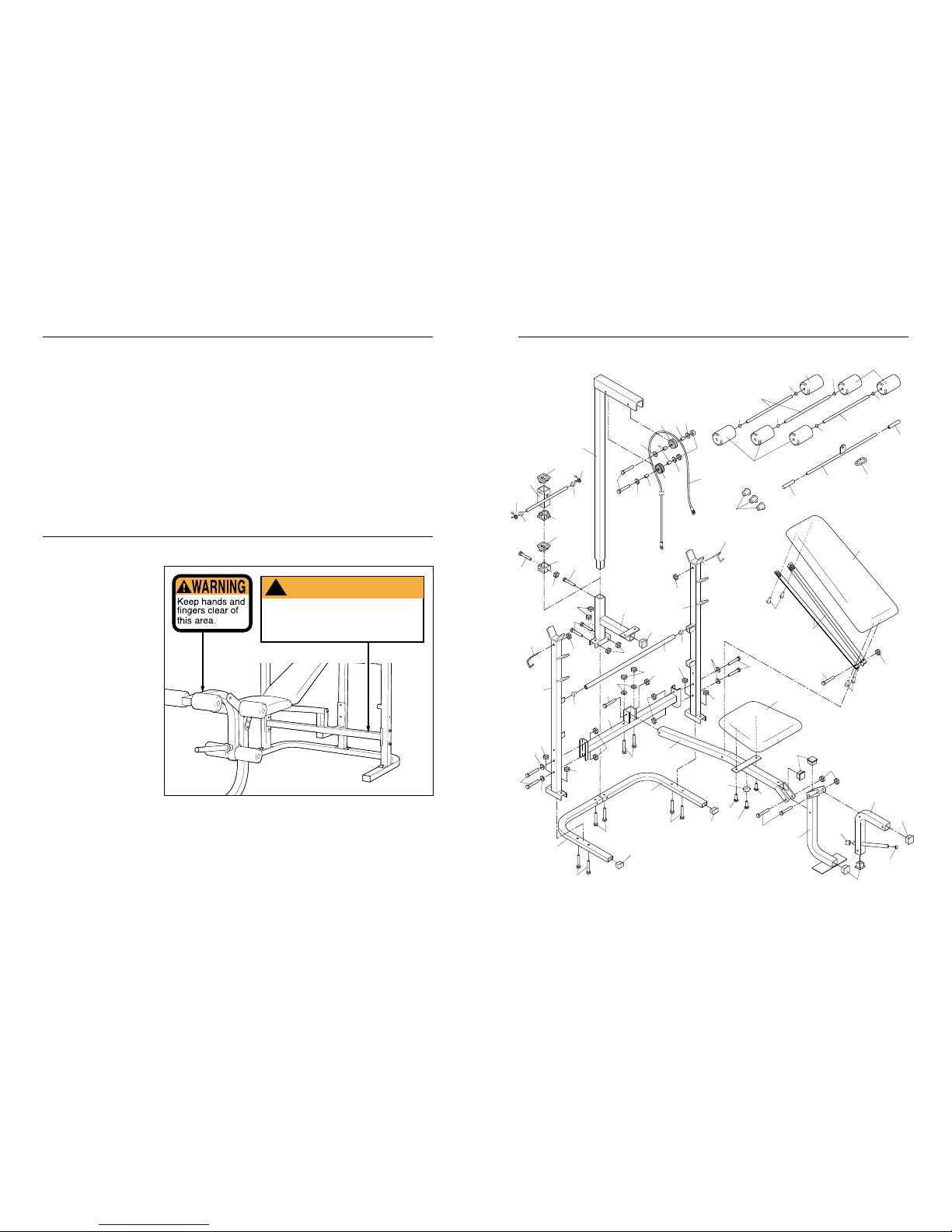
The decals shown at the
right have been placed on
your weight bench. If a decal
is missing or illegible,
please call our Customer
Service Department to order
a free replacement decal
(see the back cover of this
manual). Apply the decal in
the location shown.
WARNING DECAL PLACEMENT
• Misuse of this product may result in serious
injury.
• Read user’s manual and follow all warnings
and operating instructions prior to use.
• Do not allow children on or around machine.
• Replace label if damaged, illegible, or removed.
WARNING
!
Page 3

18
PART LIST—Model No. WEEVBE70500 R1100A
Note: “#” indicates a non-illustrated part. Specifications are subject to change without notice. See the back cover
of this manual for information about ordering replacement parts.
3
IMPORTANT PRECAUTIONS
WARNING:
To reduce the risk of serious injury, read the following important precau-
tions before using the weight bench.
1. Read all instructions in this manual before
using the weight bench.
2. Use the weight bench only as described in
this manual.
3. Use the weight bench only on a level surface.
Cover the floor beneath the weight bench to
protect the floor.
4. Inspect and tighten all parts each time you
use the weight bench. Replace any worn
parts immediately.
5. Keep children under 12 and pets away from
the weight bench at all times.
6. Always be sure there is an equal amount of
weight on each side of your barbell (not
included) when you are using it.
7. When you are using the weight carriage, be
sure there is an equal amount of weight on
each side of the weight tube.
8. Always wear athletic shoes for foot protection whilst exercising.
9. Keep hands and feet away from moving parts.
10. Do not use a barbell longer than 1,5 m with
the weight bench.
11. The weight bench does not include weights.
The weight bench is designed to support a
maximum of 230 kg, including the user, a
weight bar, and weights. Do not place more
than 140 kg, including a weight bar and
weights, on the weight rests. Do not place
more than 68 kg on the weight carriage; do
not use more than 22 kg for ab crunches. Do
not place more than 68 kg on the leg lever.
12. When using the backrest, make sure that the
adjustment tube is firmly seated in the
adjustment brackets on the uprights.
13. If you feel pain or dizziness at any time
whilst exercising, stop immediately and
begin cooling down.
14. It is the responsibility of the owner to ensure
that all users of the weight bench are adequately informed of all precautions.
15. The weight bench is intended for home use
only. Do not use the weight bench in a commercial, rental, or institutional setting.
Key No. Qty. Description
1 2 M8 x 50mm Bolt
2 6 M8 Washer
3 6 M8 x 48mm Carriage Bolt
4 6 M10 Nylon Locknut
5 4 M10 x 75mm Bolt
6 6 M6 x 16mm Screw
7 17 M8 Nylon Locknut
8 7 M8 x 68mm Bolt
9 2 Pulley
10 1 Cable
11 4 14mm x 15mm Spacer
12 2 M10 x 70mm Bolt
13 4 M10 Washer
14 2 1 1/2” Round Inner Cap
15 1 Weight Carriage
16 8 38mm x 50mm Inner Cap
17 1 Right Barbell Lock Pin
18 1 Carriage Stop
19 1 M10 x 56mm Bolt
20 1 Front Leg
21 3 1” Round Inner Cap
22 3 2 1/2” Square Bushing
23 1 Lower Lat Tower
24 1 Bumper
Key No. Qty. Description
25 6 3/4” Round Inner Cap
26 6 Foam Pad
27 3 Pad Tube
28 1 Leg Lever
29 2 Spring Clip
30 1 Cross Brace
31 1 Lat Bar
32 1 1” Angled Round Cap
33 1 Bench Frame
34 1 Cable Clip
35 1 Seat
36 1 Backrest
37 1 Adjustment Tube
38 2 Backrest Bracket
39 2 Handgrip
40 1 Right Base
41 1 Upper Lat Tower
42 1 Left Upright
43 1 Right Upright
44 1 M4 x 25mm Screw
45 3 Weight Stop
46 1 Left Barbell Lock Pin
47 1 Left Base
# 1 User’s Manual
WARNING: Before beginning this or any exercise program, consult your physician.
This is especially important for persons over the age of 35 or persons with pre-existing health problems. Read all instructions before using. ICON assumes no responsibility for personal injury or property damage sustained by or through the use of this product.
Page 4
174
BEFORE YOU BEGIN
Backrest
Lock Pins
Weight Rests
Weight Carriage
Adjustment Tube
Adjustment
Brackets
Leg Lever
Seat
High Pulley
Station
Lat Bar
Weight Tube
Thank you for selecting the WEIDER®PRO 335 weight
bench. The versatile PRO 335 weight bench is
designed to be used with your own weight set (not
included) to develop every major muscle group of the
body. Whether your goal is a shapely figure, dramatic
muscle size and strength, or a healthier cardiovascular
system, the PRO 335 weight bench will help you to
achieve the specific results you want.
For your benefit, read this manual carefully before
using the PRO 335 weight bench. If you have addi-
tional questions, please call our Customer Service
Department 0345-089009. To help us assist you,
please note the product model number and serial
number before calling. The model number is WEEVBE70500. The serial number can be found on a
decal attached to the weight bench (see the front
cover of this manual).
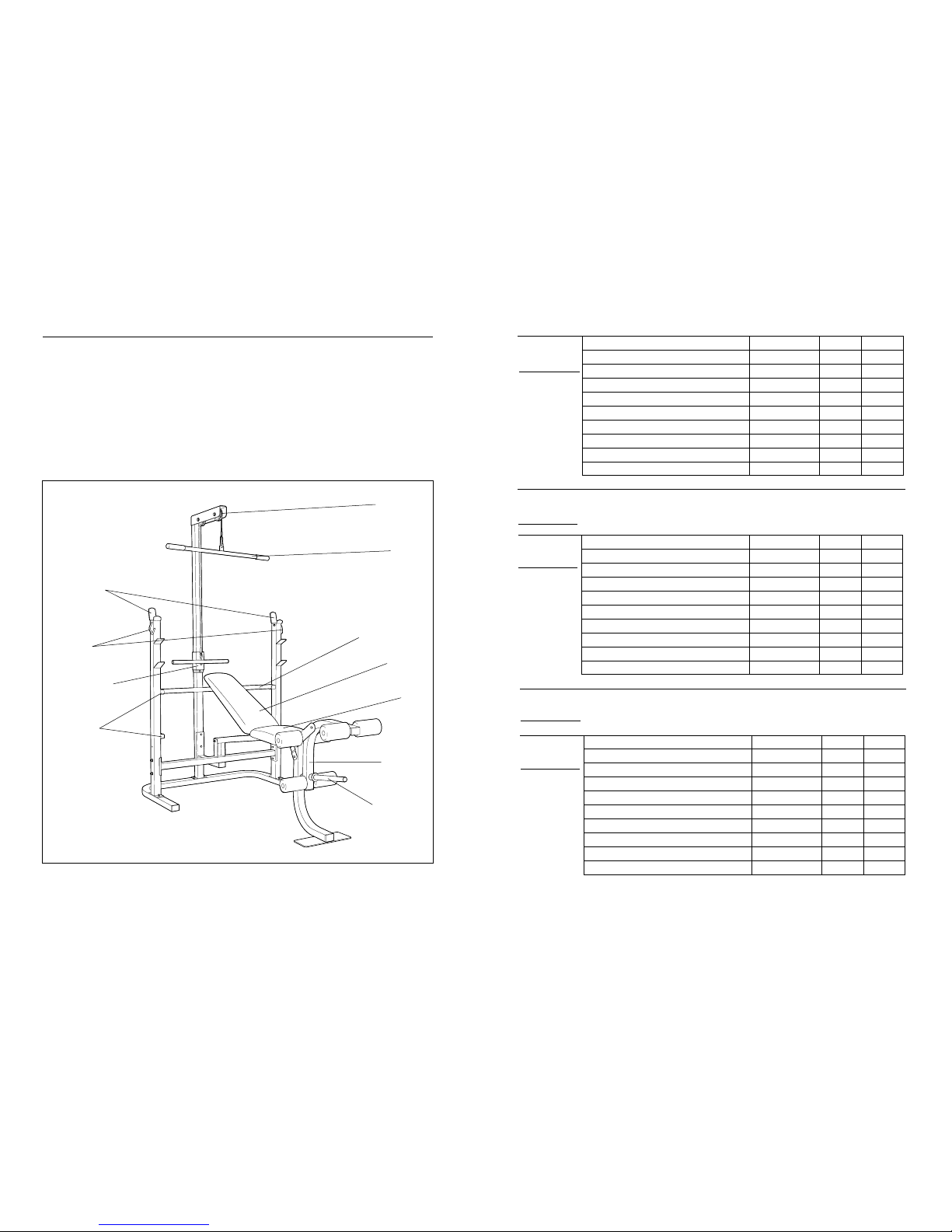
Before reading further, please review the drawing
below and familiarise yourself with the parts that are
labelled.
MONDAY
Date:
/ /
EXERCISE WEIGHT SETS REPS
EXERCISE WEIGHT SETS REPS
EXERCISE WEIGHT SETS REPS
AEROBIC EXERCISE
AEROBIC EXERCISE
TUESDAY
Date:
/ /
WEDNESDAY
Date:
/ /
THURSDAY
Date:
/ /
FRIDAY
Date:
/ /
Make photocopies of this page for scheduling and recording your workouts.
Page 5
16 5
PART IDENTIFICATION CHART
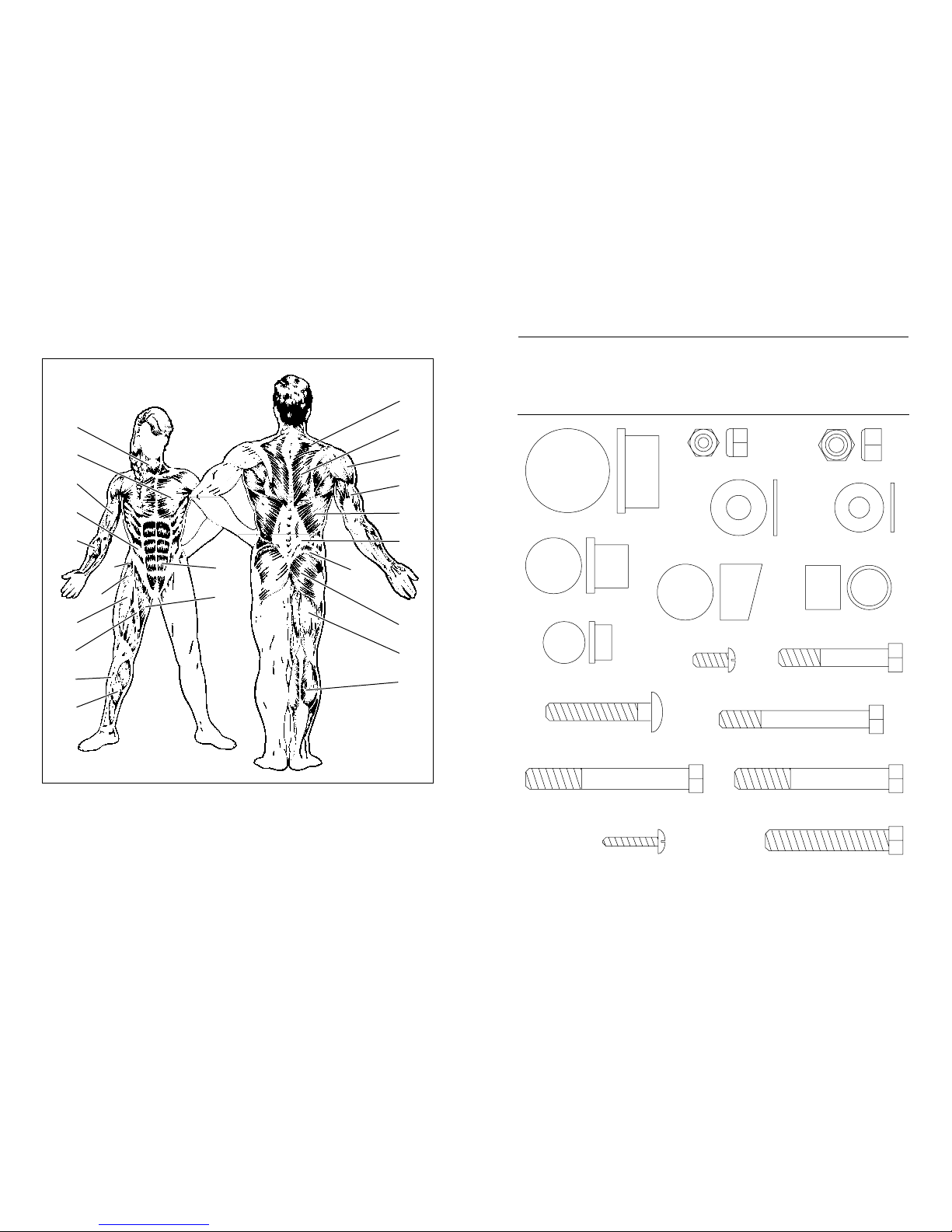
This chart is provided to help you identify the small parts used in assembly. The number in parenthesis below
each part refers to the key number of the part. The second number refers to the quantity needed for assembly.
Important: Some parts may have been pre-assembled for shipping purposes. If you cannot find a part in
the parts bags, check to see if it has been pre-assembled.
M8 Nylon Locknut (7)–17
M8 Washer (2)–6
M10 Nylon Locknut (4)–6
M10 Washer (13)–4
3/4" Round Inner Cap (25)–6
1" Angled Round Cap (32)–1
M8 x 48mm Carriage Bolt (3)–6
M6 x 16mm Screw (6)–6
1" Round Inner Cap (21)–3
M8 x 50mm Bolt (1)–2
M8 x 68mm Bolt (8)–7
14mm x 15mm Spacer (11)–4
M10 x 70mm Bolt (12)–2
1 1/2" Round Inner Cap (14)–2
M10 x 75mm Bolt (5)–4
M4 x 25mm Screw (44)–1
M10 x 56mm Bolt (19)–1
MUSCLE CHART
A. Sternomastoid (neck)
B. Pectoralis Major (chest)
C. Biceps (front of arm)
D. Obliques (waist)
E. Brachioradials (forearm)
F. Hip Flexors (upper thigh)
G. Abductor (outer thigh)
H. Quadriceps (front of thigh)
I. Sartorius (front of thigh)
J. Tibialis Anterior (front of calf)
K. Soleus (front of calf)
L. Rectus Abdominus (stomach)
M. Adductor (inner thigh)
N. Trapezius (upper back)
O. Rhomboideus (upper back)
P. Deltoid (shoulder)
Q. Triceps (back of arm)
R. Latissimus Dorsi (mid back)
S. Spinae Erectors (lower back)
T. Gluteus Medius (hip)
U. Gluteus Maximus (buttocks)
V. Hamstring (back of leg)
W. Gastrocnemius (back of calf)
N
O
P
Q
R
S
T
U
W
V
M
L
J
G
F
H
I
K
E
C
D
B
A
Page 6
15
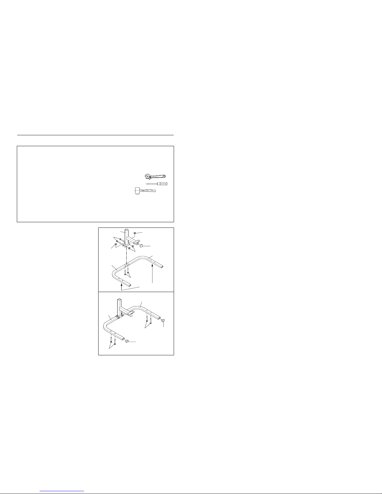
1. Before beginning assembly, be sure that you
have read and understand the information in
the box above.
Set the Right and Left Bases (40, 47) on the floor
as shown. The indented holes must be facing the
floor. Insert two M8 x 48mm Carriage Bolts (3)
into the indicated holes.
Press a 38mm x 50mm Inner Cap (16) into the
Lower Lat Tower (23). Attach the Lower Lat Tower
to the Right and Left Bases (40, 47) with two M8
x 68mm Bolts (8), two M8 x 48mm Carriage Bolts
(3), and four M8 Nylon Locknuts (7). Do not
tighten the Nylon Locknuts yet.
2. Press two 38mm x 50mm Inner Caps (16) into the
Bases (40, 47). Insert four M8 x 48mm Carriage
Bolts (3) up through the Bases.
1
16
40
47
8
7
7
7
ASSEMBLY
Before beginning assembly, carefully read the
following information and instructions:
• Place all parts of the weight bench in a cleared
area and remove the packing materials; do not
dispose of the packing materials until assembly
is completed.
• Read each assembly step before you begin.
• For help identifying the small parts used in
assembly, use the PART IDENTIFICATION
CHART on the previous page. Note: Some
small parts may have been pre-attached for shipping purposes. If a part is not in the parts bag,
check to see if it has been pre-attached.
• Tighten all parts as you assemble them, unless
instructed to do otherwise.
• As you assemble the weight bench, make sure
that all parts are oriented as shown in the drawings.
THE FOLLOWING TOOLS (NOT INCLUDED) ARE
REQUIRED FOR ASSEMBLY:
• Two (2) adjustable spanners
• One (1) standard screwdriver
• One (1) rubber mallet
• Lubricant, such as grease or petroleum jelly,
and soapy water will also be needed.
Assembly will be more convenient if you have the
following tools: Asocket set, a set of open-end or
closed-end spanners, or a set of ratchet spanners.
doing a toning workout, and 30 seconds after each set
if you are doing a weight loss workout. Plan to spend
the first couple of weeks familiarizing yourself with the
equipment and learning the proper form for each exercise.
COOLING DOWN
End each workout with 5 to 10 minutes of stretching.
Include stretches for both your arms and legs. Move
slowly as you stretch—do not bounce. Ease into each
stretch gradually and go only as far as you can without
strain. Stretching at the end of each workout is very
effective for increasing flexibility.
STAYING MOTIVATED
For motivation, keep a record of each workout. The
chart on page 17 of this manual can be photocopied
and used to schedule and record your workouts. List
the date, exercises performed, weight, and numbers of
sets and repetitions completed. Record your weight
and key body measurements at the end of every
month.
Remember, the key to achieving the greatest results is
to make exercise a regular and enjoyable part of your
everyday life.
6
The Indented Holes
must face the floor
2
40
16
16
3
3
3
23
47
Page 7
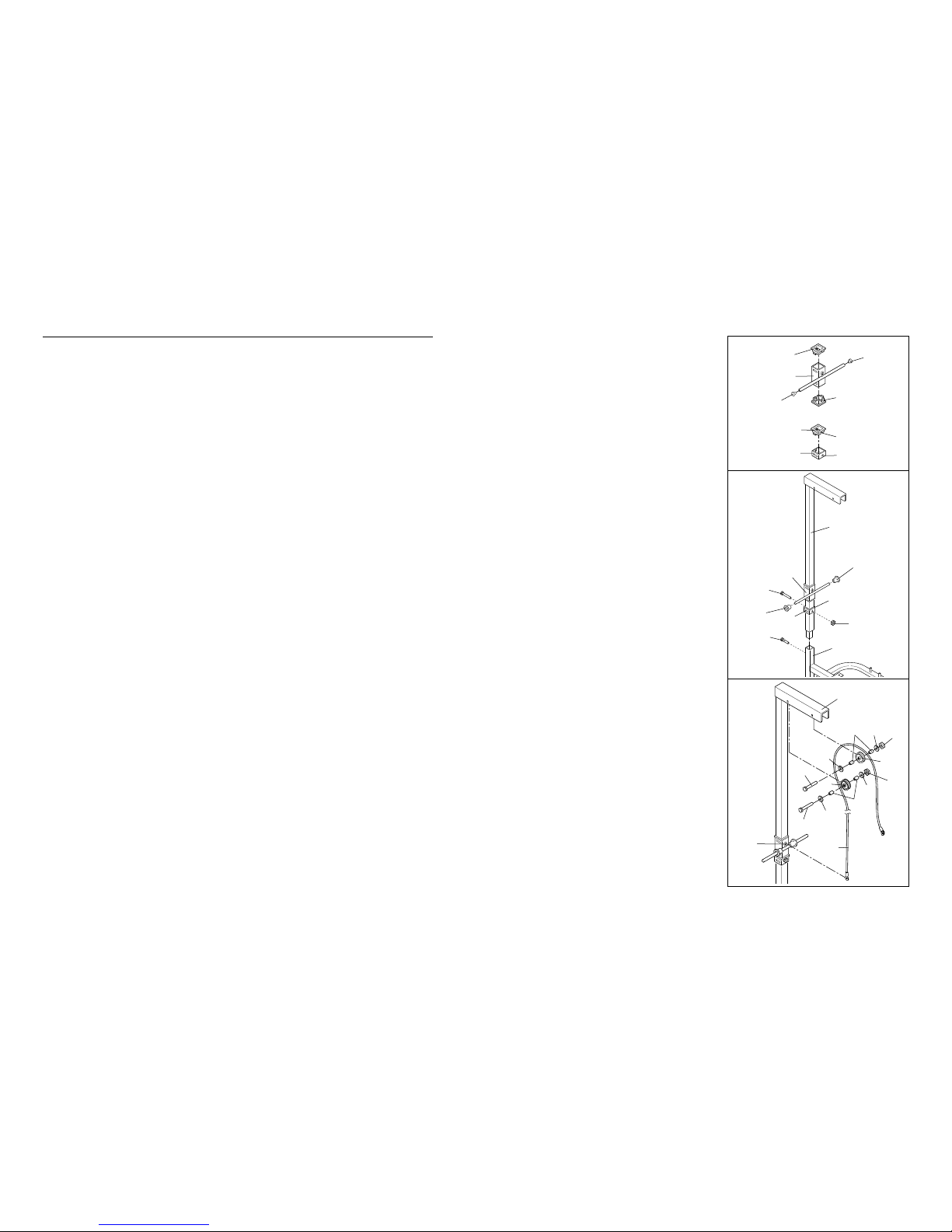
3. Press two 2 1/2” Square Bushings (22) into the
Weight Carriage (15). Press two 1” Round Inner
Caps (21) into the Weight Carriage.
Press a 2 1/2” Square Bushing (22) into the
Carriage Stop (18). The slot in the Square
Bushing must be aligned with the indicated hole
in the Carriage Stop.
4. Slide the Weight Carriage (15) onto the Upper Lat
Tower (41). The Weight Carriage must be turned
as shown.
Slide the Carriage Stop (18) onto the Upper Lat
Tower (41). The 2 1/2” Square Bushing (22) must
be facing toward the Weight Carriage (15).
Attach the Carriage Stop to the Upper Lat Tower
with an M8 x 68mm Bolt (8) and an M8 Nylon
Locknut (7) as shown.
Insert the Upper Lat Tower (41) into the Lower Lat
Tower (23). Fully tighten the M10 x 56mm Bolt (19)
into the Lower Lat Tower.
Slide a Weight Stop (45) onto each side of the
Weight Carriage (15).
5. Wrap the Cable (10) over a Pulley (9). Attach the
Pulley to the Upper Lat Tower (41) with an M10 x
70mm Bolt (12), two M10 Washers (13), two 14mm x
15mm Spacers (11), and an M10 Nylon Locknut (4).
Attach the other Pulley (9) in the same manner.
Attach the other end of the Cable (10) to the eye-
bolt on the Weight Carriage (15).
3
4
5
14 7
EXERCISE GUIDELINES
THE FOUR BASIC TYPES OF WORKOUTS
• Muscle Building
In order to increase the size and strength of your muscles, you must push your muscles to a high percentage of their capacity. You must also progressively
increase the intensity of your exercise so that your
muscles will continually adapt and grow. Each individual exercise can be tailored to the proper intensity
level by changing the amount of weight used, or the
number of repetitions or sets performed. (A “repetition”
is one complete cycle of an exercise, such as one situp. A“set” is a series of repetitions performed consecutively.)
The proper amount of weight for each exercise
depends upon the individual user. It is up to you to
gauge your limits. Select the amount of weight that
you think is right for you. Begin with 3 sets of 8 repetitions for each exercise that you perform. Rest for 3
minutes after each set. When you can complete 3 sets
of 12 repetitions without difficulty, increase the amount
of weight.
• Toning
To tone your muscles, you must push your muscles to
a moderate percentage of their capacity. Select a moderate amount of weight and increase the number of
repetitions in each set. Complete as many sets of 15
to 20 repetitions as possible without discomfort. Rest
for 1 minute after each set. Work your muscles by
completing more sets rather than by using high
amounts of weight.
• Weight Loss
To lose weight, use a low amount of weight and
increase the number of repetitions in each set.
Exercise for 20 to 30 minutes, resting for a maximum
of 30 seconds between sets.
• Cross Training
In the pursuit of a complete and well-balanced fitness
program, many have found that cross training is the
answer. We recommend that on Monday, Wednesday
and Friday, you plan weight training workouts. On
Tuesday and Thursday, plan 20 to 30 minutes of aerobic exercise, such as cycling, running or swimming.
Rest from both weight training and aerobic exercise for
at least one full day each week to give your body time
to regenerate. By combining weight training with aerobic exercise, you can reshape and strengthen your
body, plus develop a stronger heart and lungs.
PERSONALIZING YOUR EXERCISE PROGRAM
We have not specified an exact length of time for each
workout, or a specific number of repetitions or sets for
each exercise. It is very important to avoid overdoing it
during the first few months of your exercise program,
and to progress at your own pace. If you experience
pain or dizziness at any time whilst exercising, stop
immediately and begin to cool down. Find out what is
wrong before continuing. Remember that adequate
rest and a proper diet are also important.
WARMING UP
Begin each workout with 5 to 10 minutes of light
stretching and exercise to warm up. Warming up prepares your body for exercise by increasing circulation,
raising your body temperature and delivering more
oxygen to your muscles.
WORKING OUT
Each workout should include 6 to 10 different exercises. Select exercises for every major muscle group,
with emphasis on the areas that you want to develop
the most. To give balance and variety to your workouts, vary the exercises from workout to workout.
Schedule your workouts for the time of day when your
energy level is the highest. Each workout should be
followed by at least one day of rest. Once you find the
schedule that is right for you, stick with it.
EXERCISE FORM
In order to obtain the greatest benefits from exercising,
it is essential to maintain proper form.
Maintaining proper form means moving through the full
range of motion for each exercise, and moving only
the appropriate parts of the body. Exercising in an
uncontrolled manner will leave you feeling exhausted.
On the exercise poster accompanying this manual,
you will find photographs showing the correct form for
several exercises. Adescription of each exercise is
also provided, along with a list of the muscles affected.
Refer to the muscle chart on page 16 to find the locations of the muscles.
The repetitions in each set should be performed
smoothly and without pausing. The exertion stage of
each repetition should last about half as long as the
return stage. Proper breathing is important. Exhale
during the exertion stage of each repetition and inhale
during the return stroke; never hold your breath. Rest
for 3 minutes after each set if you are doing a muscle
building workout, 1 minute after each set if you are
22
22
Slot
22
15
21
21
Hole
18
41
45
45
15
8
22
19
18
23
7
41
11
11
12
12
13
13
13
9
4
4
15
13
9
10
Page 8
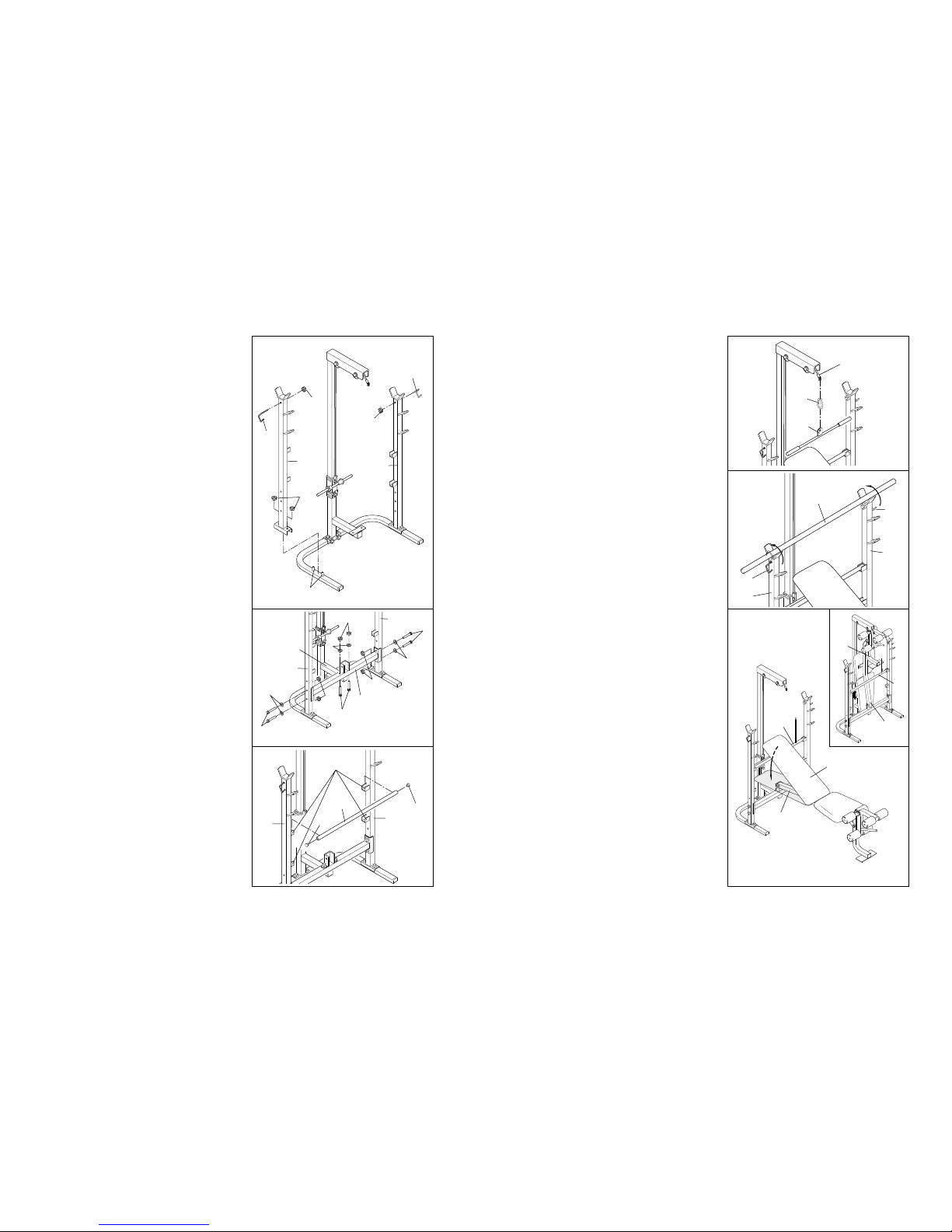
6. Slide the Left Upright (42) onto the indicated M8 x
48mm Carriage Bolts (3). Hand tighten an M8
Nylon Locknut (7) onto each Carriage Bolt. Be sure
that the Upright is turned as shown. Do not tighten
the Nylon Locknuts yet.
Attach the Right Upright (43) in the same manner.
Attach the Left Barbell Lock Pin (46) to the Left
Upright (42) with an M8 Nylon Locknut (7). Attach
the Right Barbell Lock Pin (17) to the Right Upright
(43) in the same manner.
7. Attach the Cross Brace (30) to the Lower Lat Tower
(23) with two M8 x 50mm Bolts (1), two M8
Washers (2), and two M8 Nylon Locknuts (7).
Attach the Cross Brace (30) to the Left Upright (42)
with two M8 x 68mm Bolts (8), two M8 Washers (2),
and two M8 Nylon Locknuts (7).
Attach the Cross Brace (30) to the Right Upright
(43) with two M8 x 68mm Bolts (8), two M8
Washers (2), and two M8 Nylon Locknuts (7).
Tighten all M8 Nylon Locknuts (7) used in steps
1, 6, and 7.
8. Press a 1 1/2” Round Inner Cap (14) into each end
of the Adjustment Tube (37).
Set the Adjustment Tube (37) into one set of adjustment brackets on the Left and Right Uprights (42,
43).
8
6
7
13
ATTACHING THE LAT BAR TO THE HIGH PULLEY
STATION
Attach the Lat Bar (31) to the Cable (10) with a Cable
Clip (34).
Always sit on the backrest when using the high pulley station. The backrest must be in the level position (see ADJUSTING THE BACKREST on page 12).
LOCKING THE BARBELL
To change weights whilst your barbell (not included) is
on the Uprights (42, 43), secure your barbell with the
Barbell Lock Pins (17, 46). This will reduce the possibility of the barbell tipping whilst you change weights.
Place the same amount of weight on both ends of
the barbell.
STORING THE WEIGHT BENCH
The weight bench is designed to be folded into a compact storage position when it is not in use.
First remove the Adjustment Tube (37). Lay the
Backrest (36) on the Bench Frame (33).
Fold the Bench Frame (33) up, as shown in the inset
drawing. Fold down the Front Leg (20). Set the
Adjustment Tube (37) into the upper adjustment
brackets to hold the Bench Frame in place.
8
10
31
34
Barbell
43
42
17
46
37
36
33
33
20
42
43
3
7
7
7
7
2
2
2
42
23
43
1
8
8
30
42
43
Adjustment
Brackets
14
14
37
46
17
7
7
37
Page 9
ADJUSTING THE WEIGHT BENCH
The weight bench is designed to be used with your own weight set (not included). The steps below explain how
the weight bench can be adjusted. See EXERCISE GUIDELINES on page 14 for important exercise information.
Refer also to the exercise information accompanying your weight set for additional exercises.
Inspect and tighten all parts each time you use the weight bench. Replace any worn parts immediately. The
weight bench can be cleaned with a damp cloth and a mild, non-abrasive detergent. Do not use solvents.
ATTACHING WEIGHTS TO THE WEIGHT CARRIAGE
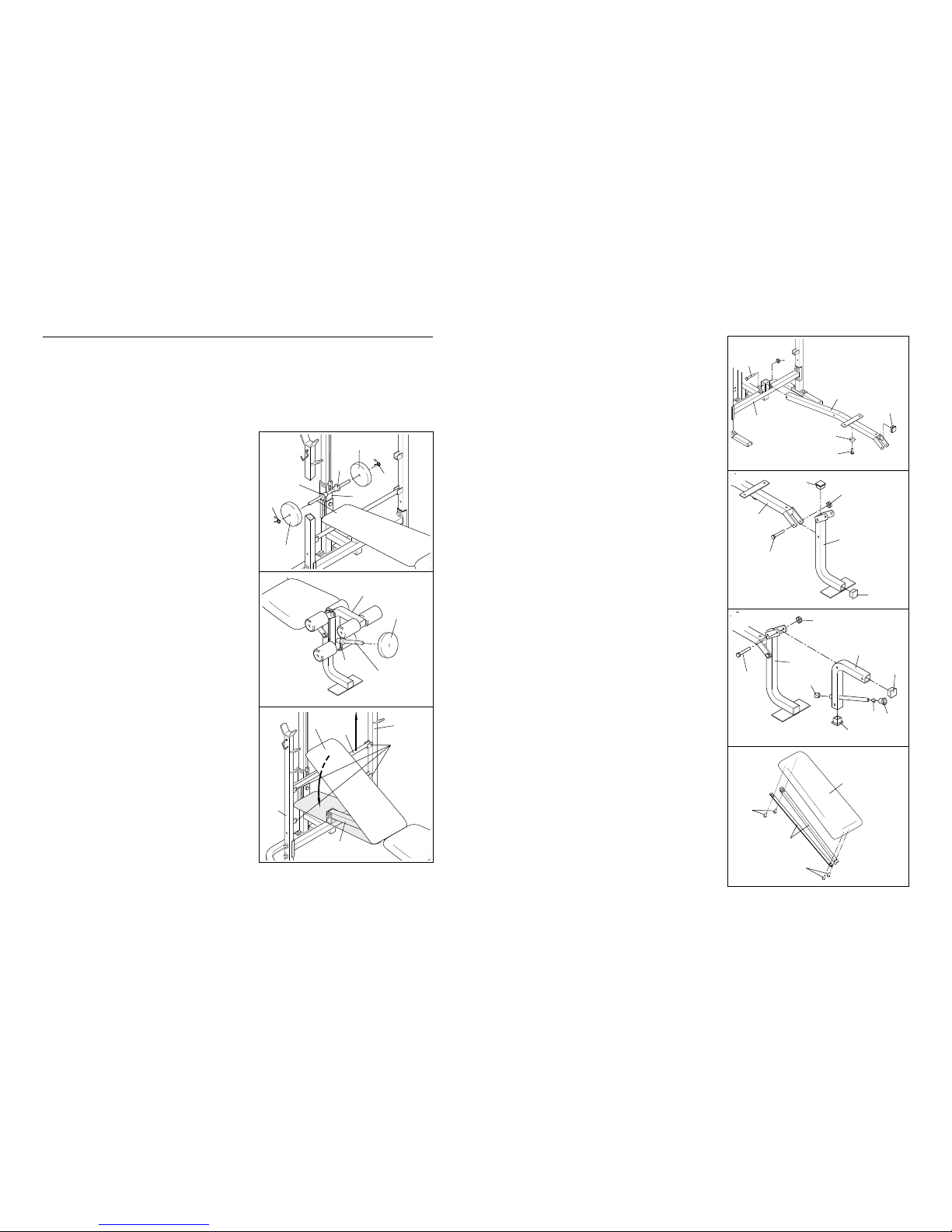
To use the lat tower, first slide a Weight Stop (45) onto
each side of the weight tube of the Weight Carriage (15).
Slide the desired amount of weight (not included) onto the
weight tube. Be sure that an equal amount of weight is on
each side of the weight tube. Secure the weights on each
side of the weight tube with a Spring Clip (29).
Do not place more than 68 kg on the Weight Carriage
(15). Due to the fact that ab crunches are an aerobic
exercise, we recommend that you do not place more
than 22 kg on the Weight Carriage whilst performing
ab crunch exercises.
ATTACHING WEIGHTS TO THE LEG LEVER
To use the Leg Lever (28), be sure there is a Weight Stop
(45) on the weight tube. Then slide the desired amount of
weight (not included) onto the weight tube.
Do not place more than 68 kg on the Leg Lever (28).
ADJUSTING THE BACKREST
The Backrest (36) can be set at three different positions:
the level position, the decline position, and the incline position.
To change the position of the Backrest (36) to either the
incline position or the level position, move the Adjustment
Tube (37) to a different set of adjustment brackets on the
Left and Right Uprights (42, 43). Set the Backrest onto the
Adjustment Tube.
To change the position of the Backrest (36) to the decline
position, remove the Adjustment Tube (37). Set the
Backrest onto the Bench Frame (33).
9. Lubricate an M10 x 75mm Bolt (5). Attach the
Bench Frame (33) to the Cross Brace (30) with the
Bolt and an M10 Nylon Locknut (4). The Bench
Frame must be turned as shown. Do not overtighten the Nylon Locknut.
Attach the Bumper (24) to the Bench Frame (33)
with an M4 x 25mm Screw (44).
Press a 38mm x 50mm Inner Cap (16) into the
Bench Frame (33).
10. Press a 38mm x 50mm Inner Cap (16) into each
end of the Front Leg (20).
Lubricate an M10 x 75mm Bolt (5). Attach the Front
Leg (20) to the Bench Frame (33) with the Bolt and
an M10 Nylon Locknut (4). Do not overtighten the
Nylon Locknut.
11. Press two 38mm x 50mm Inner Caps (16) into the
Leg Lever (28). Press a 1” Round Inner Cap (21)
into the Front Leg. Press a 1” Angled Round Cap
(32) onto the Leg Lever.
Lubricate an M10 x 75mm Bolt (5). Attach the Leg
Lever (28) to the Front Leg (20) with the M10 x
75mm Bolt (5) and an M10 Nylon Locknut (4). Do
not overtighten the Nylon Locknut.
Slide a Weight Stop (45) onto the Leg Lever (28).
12. Attach both Backrest Brackets (38) to the Backrest
(36) with four M6 x 16mm Screws (6). The
Backrest must be oriented as shown.
12
9
10
11
9
38
12
Weight
Weight
Weight
Tube
29
29
15
28
33
36
42
43
37
Adjustment
Brackets
45
Weight
45
45
4
30
33
24
16
44
16
16
33
20
4
4
28
16
32
36
6
6
5
Lubricate
Lubricate
5
5
Lubricate
20
21
45
16
Weight
Tube
Page 10
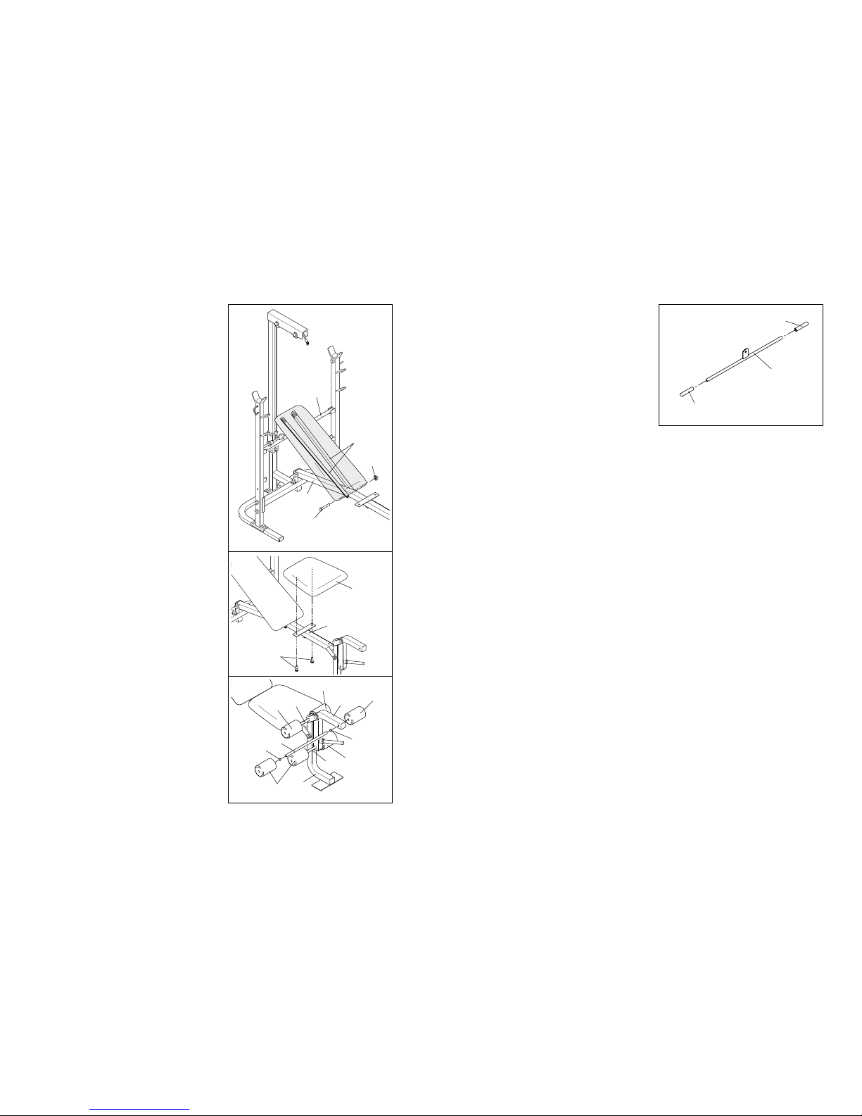
16. Wet the ends of the Lat Bar (31) with soapy water.
Slide a Handgrip (39) onto each end of the Lat Bar.
Allow the Handgrips (39) to dry thoroughly
before using the Lat Bar (31).
17. Be sure that all parts have been tightened properly. The use of all remaining parts will be explained in
ADJUSTING THE WEIGHT BENCH beginning on page 12 of this manual.
13. Lubricate an M10 x 75mm Bolt (5). Attach the
Backrest Brackets (38) to the Bench Frame (33)
with the Bolt and an M10 Nylon Locknut (4). Do not
overtighten the Nylon Locknut.
Rest the Backrest Brackets (38) on the Adjustment
Tube (37).
14. Attach the Seat (35) to the Bench Frame (33) with
two M6 x 16mm Screws (6).
15. Press 3/4” Round Inner Caps (25) into the ends of
all three Pad Tubes (27).
Insert a Pad Tube (27) through the indicated hole in
the Leg Lever (28). Insert another Pad Tube through
the other hole in the Leg Lever. Insert the remaining
Pad Tube through the hole in the Front Leg (20).
Slide two Foam Pads (26) onto each Pad Tube
(27).
1613
14
15
1110
38
37
33
35
4
6
25
25
26
26
26
27
27
27
28
20
5
Lubricate
33
26
26
31
39
39
 Loading...