

Page 1
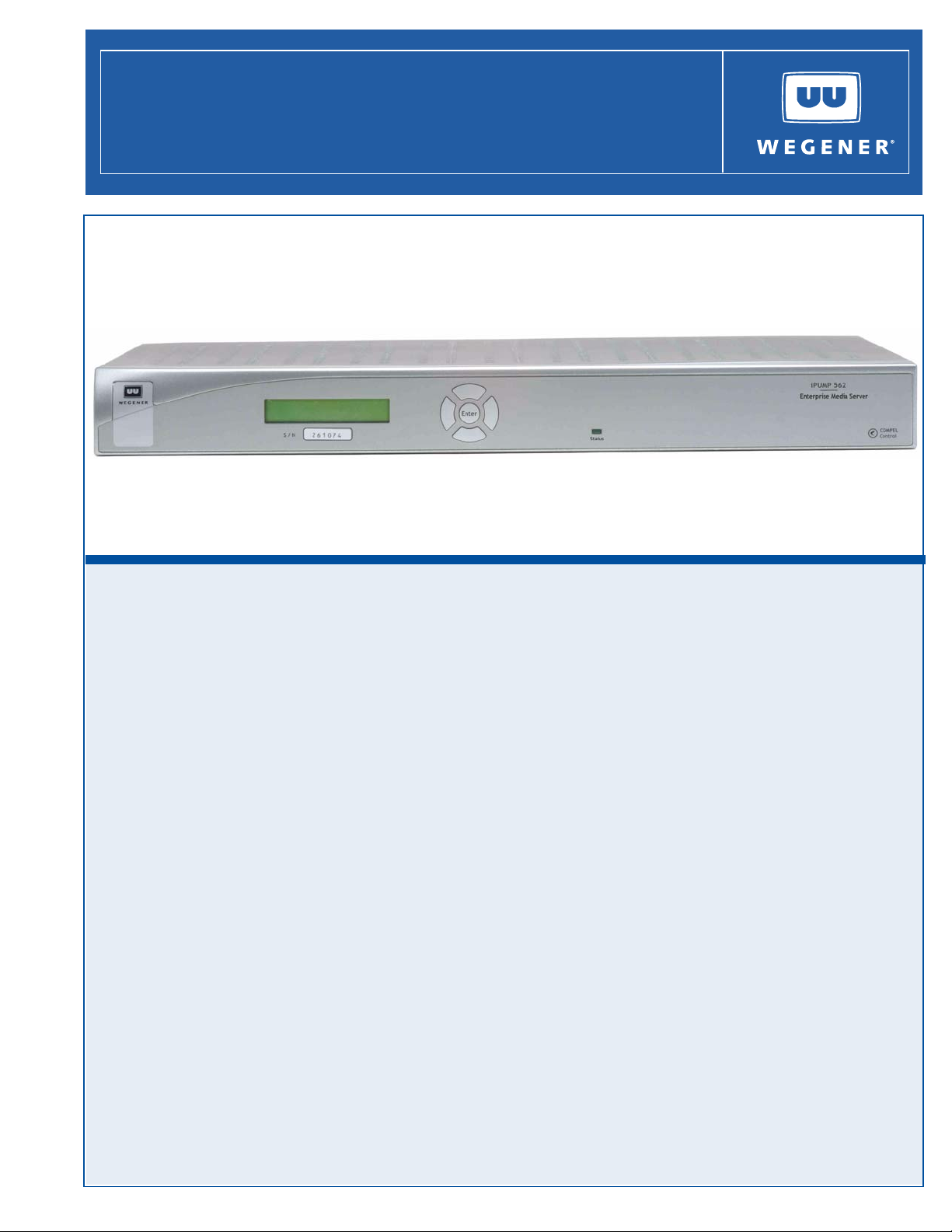
iPump 562
Digital Media Server
iPump 562
Digital Media Server
User’s Manual
800092-01 Rev. A
Page 2

Unity 552 User’s Manual
A proven world leader in digital video, audio & broadcast data systems, WEGENER's
management system is certified to
Data, drawings, and other material contained herein are proprietary to Wegener
Communications, Inc
prior written permission of
The information contained herein is subject to change without notice. Revisions may be
issued to advise of such changes and/or additions.
WEGENER
are trademarks of
their respective owners.
© 2008 Wegener Communications, Inc. All rights reserved.
Correspondence regarding this publication,
800092-01 Rev. A
First Edition: July 2008
should be forwarded to:
Wegener Communications, Inc.
Technology Park/Johns Creek
11350 Technology Circle
Duluth, GA 30097-1502
ISO 9001:2000.
., and may not be reproduced or duplicated in any form without the
Wegener Communications, Inc.
®
, Compel Control®, MediaPlan®, ENVOY, UNITY®, UNITY·IP®, and iPUMP®
Wegener Communications, Inc. All other trademarks are the prope rty of
Phone: 770-814-4000
Fax: 770-623-0698
The WEGENER iPump 562 is approved under FCC Part 15B Class A, UL/C-UL1950 3rd
Edition
, and CE [EN60950, EN55022(94), and EN55024(98)].
ii 800092-01 Rev. A www.wegener.com
Page 3

TABLE OF CONTENTS
CHAPTER 1 GENERAL INFORMATION
1.1 Manual Overview . . . . . . . . . . . . . . . . . . . . . . . . . . . . . . . . . . . . . . . . . . . . . 1
1.2 Product Overview. . . . . . . . . . . . . . . . . . . . . . . . . . . . . . . . . . . . . . . . . . . . . 1
Digital Media Sever . . . . . . . . . . . . . . . . . . . . . . . . . . . . . . . . . . . . . . . . . . . . . . . . . 1
Features and Options . . . . . . . . . . . . . . . . . . . . . . . . . . . . . . . . . . . . . . . . . . . . . . . 2
Compel™ Network Control . . . . . . . . . . . . . . . . . . . . . . . . . . . . . . . . . . . . . . . . . . . 2
1.3 iPump 562 Product Specifications . . . . . . . . . . . . . . . . . . . . . . . . . . . . . . . 2
Rear Panel View . . . . . . . . . . . . . . . . . . . . . . . . . . . . . . . . . . . . . . . . . . . . . . . . . . . 2
Rear Panel Connections . . . . . . . . . . . . . . . . . . . . . . . . . . . . . . . . . . . . . . . . . . . . . 3
External Input/Output Interfaces . . . . . . . . . . . . . . . . . . . . . . . . . . . . . . . . . . . . . . . 3
Technical Specifications . . . . . . . . . . . . . . . . . . . . . . . . . . . . . . . . . . . . . . . . . . . . . 5
RF Characteristics . . . . . . . . . . . . . . . . . . . . . . . . . . . . . . . . . . . . . . . . . . . . . . 5
Video Decoder . . . . . . . . . . . . . . . . . . . . . . . . . . . . . . . . . . . . . . . . . . . . . . . . . 6
Composite Video Output. . . . . . . . . . . . . . . . . . . . . . . . . . . . . . . . . . . . . . . . . . 7
Component Video Output . . . . . . . . . . . . . . . . . . . . . . . . . . . . . . . . . . . . . . . . . 7
Unbalanced Audio Output. . . . . . . . . . . . . . . . . . . . . . . . . . . . . . . . . . . . . . . . . 8
Audio Parameters. . . . . . . . . . . . . . . . . . . . . . . . . . . . . . . . . . . . . . . . . . . . . . . 8
Serial Port. . . . . . . . . . . . . . . . . . . . . . . . . . . . . . . . . . . . . . . . . . . . . . . . . . . . . 9
Local Hard Disk Driver (HDD). . . . . . . . . . . . . . . . . . . . . . . . . . . . . . . . . . . . . . 9
LNB DC Power (RF Port 1 ONLY) . . . . . . . . . . . . . . . . . . . . . . . . . . . . . . . . . . 9
AC Power . . . . . . . . . . . . . . . . . . . . . . . . . . . . . . . . . . . . . . . . . . . . . . . . . . . . . 9
Physical Characteristics . . . . . . . . . . . . . . . . . . . . . . . . . . . . . . . . . . . . . . . . . 10
Unity 552 User’s Manual
1.4 Safety Summary . . . . . . . . . . . . . . . . . . . . . . . . . . . . . . . . . . . . . . . . . . . . . 10
CHAPTER 2 INSTALLATION
2.1 Unpacking and Inspection. . . . . . . . . . . . . . . . . . . . . . . . . . . . . . . . . . . . . 11
2.2 Location and Mounting . . . . . . . . . . . . . . . . . . . . . . . . . . . . . . . . . . . . . . . 11
Precautions . . . . . . . . . . . . . . . . . . . . . . . . . . . . . . . . . . . . . . . . . . . . . . . . . . . . . . 11
FCC-Mandated Suppression of Radio Frequency Emissions. . . . . . . . . . . . . 11
Elevated Ambient Operating Temperatures in Rack-Mounted Units . . . . . . . 11
Reduced Air Flow . . . . . . . . . . . . . . . . . . . . . . . . . . . . . . . . . . . . . . . . . . . . . . 11
Mechanical Loading . . . . . . . . . . . . . . . . . . . . . . . . . . . . . . . . . . . . . . . . . . . . 11
Circuit Overloading . . . . . . . . . . . . . . . . . . . . . . . . . . . . . . . . . . . . . . . . . . . . . 12
Reliable Earthing. . . . . . . . . . . . . . . . . . . . . . . . . . . . . . . . . . . . . . . . . . . . . . . 12
Rack Mounting . . . . . . . . . . . . . . . . . . . . . . . . . . . . . . . . . . . . . . . . . . . . . . . . 12
Desktop Installation. . . . . . . . . . . . . . . . . . . . . . . . . . . . . . . . . . . . . . . . . . . . . 12
www.wegener.com 800092-01 Rev. A i
Page 4

CHAPTER 3 OPERATION
3.1 Controlling and Monitoring. . . . . . . . . . . . . . . . . . . . . . . . . . . . . . . . . . . . 13
3.2 Normal Functions . . . . . . . . . . . . . . . . . . . . . . . . . . . . . . . . . . . . . . . . . . . . 16
Front Panel Controls And Indicators . . . . . . . . . . . . . . . . . . . . . . . . . . . . . . . . . . . 13
LCD . . . . . . . . . . . . . . . . . . . . . . . . . . . . . . . . . . . . . . . . . . . . . . . . . . . . . . . . . 13
OSD. . . . . . . . . . . . . . . . . . . . . . . . . . . . . . . . . . . . . . . . . . . . . . . . . . . . . . . . . 13
Push-buttons . . . . . . . . . . . . . . . . . . . . . . . . . . . . . . . . . . . . . . . . . . . . . . . . . . 14
LED . . . . . . . . . . . . . . . . . . . . . . . . . . . . . . . . . . . . . . . . . . . . . . . . . . . . . . . . . 14
Diagterm Terminal (Commands) . . . . . . . . . . . . . . . . . . . . . . . . . . . . . . . . . . . . . . 15
Compel™ System Control . . . . . . . . . . . . . . . . . . . . . . . . . . . . . . . . . . . . . . . . . . . 16
Tune to a carrier. . . . . . . . . . . . . . . . . . . . . . . . . . . . . . . . . . . . . . . . . . . . . . . . . . . 17
Carrier Settings screen . . . . . . . . . . . . . . . . . . . . . . . . . . . . . . . . . . . . . . . . . . 17
Current Channel screen . . . . . . . . . . . . . . . . . . . . . . . . . . . . . . . . . . . . . . . . . 17
Configure LNB options. . . . . . . . . . . . . . . . . . . . . . . . . . . . . . . . . . . . . . . . . . . . . . 18
LNB Setup screen . . . . . . . . . . . . . . . . . . . . . . . . . . . . . . . . . . . . . . . . . . . . . . 18
Monitor Signal Quality . . . . . . . . . . . . . . . . . . . . . . . . . . . . . . . . . . . . . . . . . . . . . . 19
Signal Quality Setup screen . . . . . . . . . . . . . . . . . . . . . . . . . . . . . . . . . . . . . . 19
Indicator Threshold screen . . . . . . . . . . . . . . . . . . . . . . . . . . . . . . . . . . . . . . . 20
Signal Strength Meter screen . . . . . . . . . . . . . . . . . . . . . . . . . . . . . . . . . . . . . 21
Set Subtitling options. . . . . . . . . . . . . . . . . . . . . . . . . . . . . . . . . . . . . . . . . . . . . . . 21
Subtitling Setup screen . . . . . . . . . . . . . . . . . . . . . . . . . . . . . . . . . . . . . . . . . . 21
Configure the unit for operation . . . . . . . . . . . . . . . . . . . . . . . . . . . . . . . . . . . . . . . 22
Advanced Setup screen . . . . . . . . . . . . . . . . . . . . . . . . . . . . . . . . . . . . . . . . . 22
Unit Setup screen . . . . . . . . . . . . . . . . . . . . . . . . . . . . . . . . . . . . . . . . . . . . . . 23
Set Decoder Options. . . . . . . . . . . . . . . . . . . . . . . . . . . . . . . . . . . . . . . . . . . . 24
Setup Audio. . . . . . . . . . . . . . . . . . . . . . . . . . . . . . . . . . . . . . . . . . . . . . . . . . . 25
Set LAN-based Decode options . . . . . . . . . . . . . . . . . . . . . . . . . . . . . . . . . . . 26
Set LAN IP Networking options. . . . . . . . . . . . . . . . . . . . . . . . . . . . . . . . . . . . 26
Set Terminal options . . . . . . . . . . . . . . . . . . . . . . . . . . . . . . . . . . . . . . . . . . . . 27
Set Printer Options . . . . . . . . . . . . . . . . . . . . . . . . . . . . . . . . . . . . . . . . . . . . . 28
Set User Relay . . . . . . . . . . . . . . . . . . . . . . . . . . . . . . . . . . . . . . . . . . . . . . . . 29
Set Date and Time information . . . . . . . . . . . . . . . . . . . . . . . . . . . . . . . . . . . . 29
Set Unit Label . . . . . . . . . . . . . . . . . . . . . . . . . . . . . . . . . . . . . . . . . . . . . . . . . 30
Switch Application (to different software versio n) . . . . . . . . . . . . . . . . . . . . . . 30
Monitor Status Information. . . . . . . . . . . . . . . . . . . . . . . . . . . . . . . . . . . . . . . . . . . 31
Unit Status screen. . . . . . . . . . . . . . . . . . . . . . . . . . . . . . . . . . . . . . . . . . . . . . 31
Signal Quality screen . . . . . . . . . . . . . . . . . . . . . . . . . . . . . . . . . . . . . . . . . . . 32
Current Quality screen . . . . . . . . . . . . . . . . . . . . . . . . . . . . . . . . . . . . . . . . . . 32
History This Setting screen . . . . . . . . . . . . . . . . . . . . . . . . . . . . . . . . . . . . . . . 33
Elapsed Times screen. . . . . . . . . . . . . . . . . . . . . . . . . . . . . . . . . . . . . . . . . . . 34
Query Network History . . . . . . . . . . . . . . . . . . . . . . . . . . . . . . . . . . . . . . . . . . 34
Display LAN IP Network information . . . . . . . . . . . . . . . . . . . . . . . . . . . . . . . . 35
Find Software Version information . . . . . . . . . . . . . . . . . . . . . . . . . . . . . . . . . 35
Clear Statistics used for diagnosis . . . . . . . . . . . . . . . . . . . . . . . . . . . . . . . . . 36
Play out play lists of media files . . . . . . . . . . . . . . . . . . . . . . . . . . . . . . . . . . . 37
ii 800092-01 Rev. A www.wegener.com
Page 5

Unity 552 User’s Manual
3.3 View Alarms/Warnings. . . . . . . . . . . . . . . . . . . . . . . . . . . . . . . . . . . . . . . . 37
CHAPTER 4 SEARCH FUNCTIONS
4.1 Perms/Temps/Searching & Settings. . . . . . . . . . . . . . . . . . . . . . . . . . . . . 41
4.2 Settings Table (or Search Table) . . . . . . . . . . . . . . . . . . . . . . . . . . . . . . . 42
4.3 Signal Quality Monitoring . . . . . . . . . . . . . . . . . . . . . . . . . . . . . . . . . . . . . 42
4.4 Frequency Tagging . . . . . . . . . . . . . . . . . . . . . . . . . . . . . . . . . . . . . . . . . . 43
General Rules . . . . . . . . . . . . . . . . . . . . . . . . . . . . . . . . . . . . . . . . . . . . . . . . . . . . 43
CHAPTER 5 CUSTOMER SERVICE
5.1 Warranty . . . . . . . . . . . . . . . . . . . . . . . . . . . . . . . . . . . . . . . . . . . . . . . . . . . 45
5.2 Technical Support . . . . . . . . . . . . . . . . . . . . . . . . . . . . . . . . . . . . . . . . . . . 45
APPENDIX 1 TERMINAL DIAGTERM COMMANDS. . . . . . . . . . . . . . . . . . . . . . . . . . . . . . . . . . 47
PPENDIX 2 MENU TREE . . . . . . . . . . . . . . . . . . . . . . . . . . . . . . . . . . . . . . . . . . . . . . . . . . 51
A
A
PPENDIX 3 RMA REQUEST FORM . . . . . . . . . . . . . . . . . . . . . . . . . . . . . . . . . . . . . . . . . . 53
www.wegener.com 800092-01 Rev. A iii
Page 6

This page intentionally left blank
iv 800092-01 Rev. A www.wegener.com
Page 7

Unity 552 User’s Manual
LIST OF TABLES
Table 1.1: iPump 562 Interconnect Descriptions ........................................................3
Table 1.2: iPump 562 External Input/Output Interfaces ..............................................3
Table 1.3: iPump 562 RF Characteristics ...................................................................5
Table 1.4: iPump 562 Video Decoder .........................................................................6
Table 1.5: iPump 562 Composite Video Output ..........................................................7
Table 1.6: iPump 562 Component Video Output ........................................................8
Table 1.7: iPump 562 Audio Decoder .........................................................................8
Table 1.8: iPump 562 Unbalanced Audio Output ........................................................8
Table 1.9: iPump 562 Audio Parameters ....................................................................8
Table 1.10: iPump 562 Serial Port ................................................................................9
Table 1.11: iPump 562 HDD .........................................................................................9
Table 1.12: iPump 562 LNB DC Power (RF Port 1 ONLY) ...........................................9
Table 1.13: iPump 562 AC Power .................................................................................9
Table 1.14: iPump 562 Physical Characteristics .........................................................10
Table 3.1: Menu Navigation using Push-buttons ......................................................14
Table 3.2: iPump 562 Front Panel Status LED Alarm and Warning Indications .......15
Table 3.3: Channel Information Options .......... ... .......................................... ... .... ... ..18
Table 3.4: LNB configuration options ........................................................................19
Table 3.5: Indicator Threshold screen options ..........................................................21
Table 3.6: Subtitling Setup screen options ...............................................................22
Table 3.7: Video Decoder Options ............................................................................24
Table 3.8: Audio Output Options ...............................................................................25
Table 3.9: LAN Decode Options ...............................................................................26
Table 3.10: Networking Configuration Settings ...........................................................27
Table 3.11: Terminal Options ......................................................................................28
Table 3.12: User Relay Setup Options .......................................................................29
Table 3.13: Date and Time Information Settings ........................................................30
Table 4.1: Settings Parameters for the iPump 562 ...................................................41
Table 4.2: iPump 562 Settings Groups .....................................................................42
Table 4.3: Signal Quality Information ........................................................................43
Table Apx 1.1:Diagterm Group Commands ........................................ ... .........................47
Table Apx 1.2:Diagterm Individual Commands ...............................................................49
www.wegener.com 800092-01 Rev. A v
Page 8

This page intentionally left blank
vi 800092-01 Rev. A www.wegener.com
Page 9

Unity 552 User’s Manual
LIST OF FIGURES
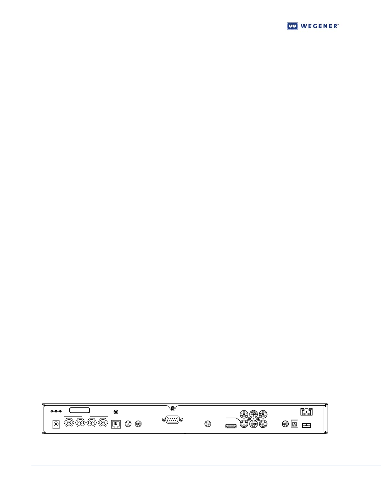
Figure 1.1: iPump 562 Rear Panel ...............................................................................2
Figure 3.1: iPump 562 Front Panel ............................................................................13
Figure 3.2: OSD Main Menu ......................................................................................14
Figure 3.3: Diagterm Terminal Help Screen ...............................................................15
Figure 3.4: iPump 562 OSD Carrier Settings Screen ........................ .................... .....17
Figure 3.5: iPump 562 OSD Current Channel Screen ...............................................18
Figure 3.6: iPump 562 OSD LNB Setup Screen ........................................................19
Figure 3.7: iPump 562 OSD Signal Quality Setup Screen .........................................20
Figure 3.8: iPump 562 OSD Indicator Threshold Screen ...........................................20
Figure 3.9: iPump 562 OSD Signal Strength Meter Screen .......................................21
Figure 3.10: iPump 562 OSD Subtitling Screen ...........................................................22
Figure 3.11: iPump 562 OSD Advanced Setup ............................................................23
Figure 3.12: iPump 562 OSD Unit Setup .....................................................................23
Figure 3.13: iPump 562 OSD Decoder Setup ..............................................................24
Figure 3.14: iPump 562 OSD Audio Setup ..................................................................25
Figure 3.15: iPump 562 OSD Decoder Source ............................................................26
Figure 3.16: iPump 562 OSD LAN IP Setup ................................................................27
Figure 3.17: iPump 562 OSD Terminal Setup ..............................................................28
Figure 3.18: iPump 562 OSD Printer Options ..............................................................28
Figure 3.19: iPump 562 OSD User Relay Setup ..........................................................29
Figure 3.20: iPump 562 OSD Date/Time Setup ...........................................................30
Figure 3.21: iPump 562 OSD Application Switch .........................................................31
Figure 3.22: iPump 562 OSD Unit Status ....................................................................32
Figure 3.23: iPump 562 OSD Signal Quality Status .....................................................32
Figure 3.24: iPump 562 OSD Current Quality ..............................................................33
Figure 3.25: iPump 562 OSD History This Setting .......................................................33
Figure 3.26: iPump 562 OSD Elapsed Times ..............................................................34
Figure 3.27: iPump 562 OSD Network History .............................................................35
Figure 3.28: iPump 562 OSD LAN IP Info ....................................................................35
Figure 3.29: iPump 562 OSD Version Info ...................................................................36
Figure 3.30: iPump 562 OSD Clear Signal Counters ...................................................36
Figure 3.31: iPump 562 OSD Clear Signal Counters ...................................................37
Figure 3.32: iPump 562 OSD Main Menu ....................................................................38
Figure 3.33: iPump 562 OSD Alarms / Warnings .........................................................38
www.wegener.com 800092-01 Rev. A vii
Page 10

Figure 3.34: iPump 562 OSD Display Current Warnings .............................................39
Figure Apx 3.1:RMA Request Form ..............................................................................53
viii 800092-01 Rev. A www.wegener.com
Page 11

CHAPTER 1 GENERAL INFORMATION
1.1 Manual Overview
This manual provides instructions and reference information for the proper installation and
operation of the
The manual is divided into the following chapters and appendices:
1. General Information - A description of the product, its functions and specifications,
and a glossary of terms.
2. Installation - Procedures and information for the correct and safe installation.
3. Operation - Instructions on starting and operating the product.
4. Search Functions - Information on settings, pararmeters, modes, and signal
monitoring.
5. Customer Service - Our warranty and information about obtaining help.
Appendix 1 - Terminal Diagterm Commands.
Unity 552 User’s Manual
WEGENER iPump 562.
Appendix 2 - Menu Tree of LCD navigation.
Appendix 3 - RMA Request Form.
An Index of keywords is also provided to help you quickly locate needed information.
Please e-mail any suggestions or comments concerning this manual to
[email protected]. If you pr efer to post through the mail, please send your comm ents
to the address below. If you have substantial or complex changes to recommend, our
preference is that you copy the page(s) in question, mark your changes on that copy, and
fax or mail us the copy. We always appreciate constructive criticism.
Address:
Attn: Manuals
Wegener Communications, Inc.
Technology Park / Johns Creek
1 1350 Technology Circle
Duluth, GA 30097-1502
Fax number: (770) 497-0411
1.2 Product Overview
Digital Media Sever
www.wegener.com 800092-01 Rev. A 1
The iPump 562 Digital Media Sever is an advanced multimedia appliance that allows
simple, efficient management of both live and recorded digital video, audio and data
content. The single unit receives, decodes and plays out broadcast quality transmission
using DVB-S2 modulation and MPEG-4/H.264 video compression saving 40-70%
bandwidth utilization. The extra bandwidth may be used to launch additional video and data
services. An integrated
mixed network of WEGENER servers. It also facilitates global deployment by supporting
both, PAL and NTSC video.
Compel network control offers flexibility and power to manage a
Page 12
General Information
Features and Options
Some of the features and options of iPump 562 are highlighted below .
Optimize bandwidth utilization by decoding MPEG-2 and MPEG-4/H.264 compression
Save bandwidth with compliance to DVB-S2 QPSK /8PSK & DBV-S modulations
Deploy in global markets by employing PAL and NTSC video formats
Provide viewing options for both, HD and SD audiences
Play out media files and play lists received from Compel uplink (Un-timed)
Broadcast in multiple language by configuring four audio ports as mono or stereo
Provide Subtitling, Tele-text services and Text "Crawling"
Support Closed Captioning Line 21 with ATSC and Divicom formats
Switch seamlessly between media sources ("Splicing")
Simultaneously play media while receiving file downloads
Insure integrity of files downloaded over satellite from uplink using Assured File Delivery (AFD)
Decode LAN-based MPEG-2 and H.264 transport stream
Enhance control operations using two Relay outputs and one Contact Closure input
Print on Serial Port the text messages received form Compel
Monitor using SNMP Protocol
Digital audio/video output on HDMI with HDCP copy protection
Digital audio output on S/PDIF (PCM and Dolby Digital)
One HD component video and two composite video outputs
Option for 4-RF ports and Universal or Standard LNB DC Power on RF Port 1
Allow local control of OSD menu using Remote IR (optional)
Save footprint with 1RU rack-mount or desktop chassis and a universal power supply
The iPump 562 has integral support for the following Compel features:
Compel Satellite network control and Compel/CA Conditional Access
Internal SIM smartcard accommodating Compel CA cipher
Audio level controlled through Compel network
Field-upgradeable software downloads over RF Network using Compel
Compel™ Network Con trol
Compel gives you the power to manage a ne twork of iPump 562s and other Unity IRDs with
unparalleled functionality. With its uniqu e network management feature s, such as grouping,
-
receiver control and scheduling, the operator can command individual groups of receivers to
switch, tune, or "output" video or data targeted sp ecifically for that one receiver or group of
receivers. This ability can be utilized for unequalled disaster recovery for business critical
operations.
1.3 iPump 562 Product Specifications
Rear Panel View
S/N
DC IN
12 V 5 A
000000
RF IN
Manufa cture d under licens e f rom
Dolby La borator ies.
"Dolby" and the double- D symbol
are trademarks of Dolby Laboratories.
RS232
4321
L
61
R
Figure 1.1: iPump 562 Rear Panel
GPIO
DIM STANDARDS
.000 [.00]
1.000 [25.40]
.000 [.00]
STANDARD
DECIMAL-METRIC_ALT
ASSOCITIVE
NON-ASSOCITIVE
0.0010
STANDARD
1.000 [25.40]
NON-ASSOCITIVE
1.000
DECIMAL-METRIC_ALT_LIB
NON-ASSOCITIVE
1.000 [25.40]
.001 [0.03]
1.000 [25.40]
.001 [0.03]
DECIMAL-METRIC_ALT-LIB
ASSOCITIVE
.001 [0.03]
DECIMAL-METRIC_ALT
ASSOCITIVE
FRACTION-METRIC_ALT
DECIMAL-METRIC_ALT
NON-ASSOCITIVE
NON-ASSOCITIVE
1 [25.40]
1.000 [25.40]
FRACTION-METRIC_ALT
ASSOCITIVE
0 [0.03]
PLOT STANDARDS
Acrobat PDF Writer A-SIZE
Acrobat PDF Writer B-SIZE
HP 6310 A-SIZE
HP 6310 B-SIZE
HP 1220C A-SIZE
HP 1220C B-SIZE
JPEG Hi-Res 1600 x 1200
XANTE 8200 A-SIZE
XANTE 8200 B-SIZE
COMPOSITE
VIDEO
MON
AUDIO 2
0.1A @ 30VDC
AUDIO 1
HDMI
Pb
L
Y
C-VIDEO
COMPONENT
VIDEO
S/PDIF S/PDIF
ETHERNET
USB
Pr
R
2 800092-01 Rev. A www.wegener.com
Page 13
Unity 552 User’s Manual
Rear Panel Connections
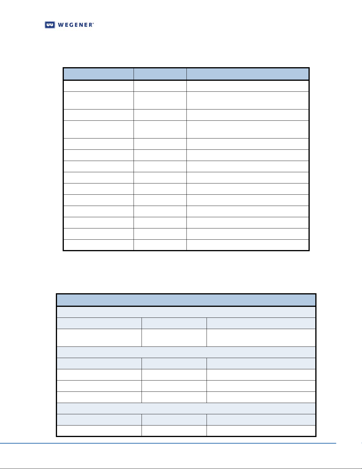
DC IN M Power Jack +12 V DC 5 A
RF Switch IN - Port 1 F 950 to 2150 MHz signal accepted; Universal/Std
RF Switch IN - Port 2, 3, 4 F 950 to 2150 MHz signal accepted; No LNB power
RS-232 Port RJ-12 Serial Asynchronous for terminal, printer or Aux
Audio OUT 1 (R&L) 2 RCA Phone Jacks Audio stereo
Audio OUT 2 (R&L) 2 RCA Phone Jacks Audio stereo
Composite Video RCS Phone Jack Composite Video Monitor NTSC or PAL at 1 Vp-p
C-Video RCS Phone Jack C-Video NTSC or PAL at 1 Vp-p
Component Video 3 RCS Phone Jacks Component HD/SD Video YPbPr
HDMI Type A receptable High Definition Multimedia Interface (Digital A/V)
S/PDIF RCA Phono Jack S/PDIF Coax Digital Audio
The iPump 562 rear panel provides following connections:
Table 1.1: iPump 562 Interconnect Descriptions
Port / Signal Connector Type Description
Pwr
Data
S/PDIF Optical TosLink S/PDIF Fiber Digital Audio
ETHERNET RJ-45 ETHERNET 10/100 BaseT
USB USB USB V2.0 port
External
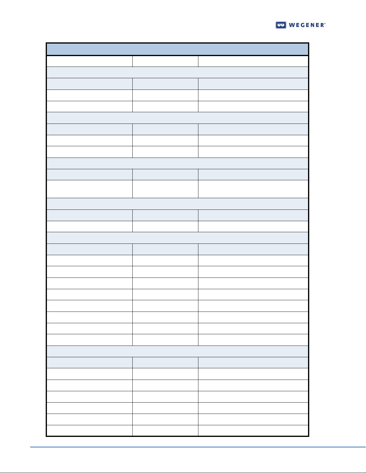
The details on each of the interfaces are described below:
Input/Output
Interfaces
Connector Input/Output Description
4 RF Inputs from LNB Port 1 I/O; Port 2-4 Input Port 1 Universal/ Standard LNB Port 2-4 No
Connector Input/Output Description
Component Y Output Green RCA
Component Pb Output Blue RCA
Table 1.2: iPump 562 External Input/Output Interfaces
External Input/Output Interfaces
RF
LNB Voltage
Component Video
Component Pr Output Red RCA
Composite Video
Connector Input/Output Description
Composite Video MON Output Yellow RCA
www.wegener.com 800092-01 Rev. A 3
Page 14
General Information
External Input/Output Interfaces
C-Video Output Yellow RCA
Audio 1 and 2 (two analog audio ports)
Connector Input/Output Description
Right Audio Output Red RCA Unbalanced
Left Audio Output White RCA Unbalanced
S/PDIF Digital Audio
Connector Input/Output Description
1 Output Coax/Electrical
2 Output TosLink/Optical
HDMI Digital Audio/Video
Connector Input/Output Description
HDMI I/O Digital Audio/Video; HDCP Copy Protection;
Display Data Channel
USB
Connector Input/Output Description
1 I/O USB V2.0 Port
10/100 BaseT (RJ-49) Ethernet Auto Detect
Connector Pin Input/Output Description
1 Output TXD +
2 Output TXD 3 Input RXD +
4 NA No Connection
5 NA No Connection
6 Input RXD 7 NA No Connection
8 NA No Connection
RS-232 Serial Port Phone Jack
Connector Pin Input/Output Description
1 NA No Connection
2 Output RXDB Data
3 Input TXDB Data
4 NA No Connection
5 NA Ground
6 NA +5V DC
4 800092-01 Rev. A www.wegener.com
Page 15
Unity 552 User’s Manual
External Input/Output Interfaces
Contact Closure GPIO DB-9 Female
Connector Pin Input/Output Description
1 Alarm Common
2 Alarm Normally Open
3 Contact Closure Common
4 No Connection
5 Input Contact Closure GPIO Input
(Factory use only)
6 Alarm Normally Closed
7 Contact Closure Normally Closed
8 Contact Closure Normally Open
9 NA Ground
Power DC IN 12 V 5 A
Connector Input/Output Description
Standard IEC Input 115 or 230 V AC
Technical Specifica tions
-
The following tables detail the technical specifications for the iPump 562.
RF Characteristics
Table 1.3: iPump 562 RF Characteristics
RF Characteristics
RF Input Connector Type F
Input Frequency Range 950 - 2150 MHz
Input Level Range -25 to -65dBm
Maximum Aggregate Input Power -8 dBm at max input signal
Input Impedance 75 ohms
Input VSWR < 2.5:1
Input Noise Figure 8 dB MAX at minimum input level
L.O. Leakage at Input < -55 dBm
Demodulator
DVB-S QPSK
DVB-S2 QPSK
DVB-S2, 8PSK
Max Symbol-rate S2 = 30 Msps; S1 = 45 Mbps
www.wegener.com 800092-01 Rev. A 5
FEC Rate 1/2, 2/3, 3/4, 5/6, or 7/8 (1.0 to 45 MBaud) ½, 2/3,
¾, 4/5, 5/6, 7/8, 9/10 (2 to 30 MBaud) 2/3, ¾, 5/6, 8/9, 9/10
(3 to 30 MBaud) Convert Symbol Rate Fs to Transport Rate
Ft by: (2R*Fs)*(188/204)=Ft, where 'R' is inner FEC code
ratio, either R=1/2, 2/3, 3/4, 5/6, or 7/8.
Page 16
General Information
Aggregate MPEG Transport Rate 8PSK = 80.346; S1 QPSK = TBD 2.5 to 48.38 Mbps (limited
Max/Min Eb/No @ Video Threshold S1QPSK:
RF Characteristics
by max symbol-rate and inner FEC chosen), defined for
188-byte MPEG transport packets
FEC: Eb/No (dB)
1/2: 4.5
2/3: 5.0
3/4: 5.5
5/6: 6.0
7/8: 6.4
S2QPSK:
FEC: Eb/No (dB)
1/2: 1.5
3/5: 2.0
2/3: 2.4
3/4: 2.8
4/5: 3.2
5/6: 3.5
8/9: 4.2
9/10: 4.4
S28PSK:
FEC: Eb/No (dB)
3/5: 3.5
2/3: 4.1
3/4: 4.9
5/6: 5.9
8/9: 6.9
9/10: 7.2
Video Decoder
Table 1.4: iPump 562 Video Decoder
Video Decoder
Compression System MPEG-2/MPEG-4 and H.264 - Standard and High
Definition
Analog (Composite) Output Formats NTSC or PAL
6 800092-01 Rev. A www.wegener.com
Page 17
Video Decoder
Supported Digital Video Resolutions SD:
480I / 29.97
480P / 59.94
576I / 25
576P / 50
Horizontal: 720, 704, 640, 544, 528, 480 and 352
HD:
1080I / 29.97
Horizontal: 1920, 1440, 1280, and 960
1080I / 25
Horizontal: 1920, 1440, 1280, and 960
720P / 50
Horizontal: 1280, 960, and 640
Unity 552 User’s Manual
720P / 59.94
Horizontal: 1280, 960, and 640
Supported Color Space Sampling
Scheme
4:2:0 All Supported Formats
4:2:2 SD Formats
Composite Video Output
Table 1.5: iPump 562 Composite Video Output
Composite Video Output
Line 21 Closed captioning Divicom and ATSC EIA-608-B
TELETEXT CCIR/ITU-R Broadcast Teletext System B
Output Level 1.0 Vp-p, < 5% Deviation
Output Impedance 75 Ohms
Multi-burst Frequency Response NTSC: From 0.5 to 4.2 MHz: < +0/-3 dB PAL: From 0.5
to 4.2 / 5.8 MHz: < +0/-3
Differential Gain < 3%
Differential Phase < 3 Degrees
Line Time W-form Distortion < 2% p-p
Field Time W-form Distortion < 2% p-p
Component Video Output
All specs below are presumed for NTSC and PAL unless otherwise specified. Tested per
RS250C. Tested at max resolution with ~6 Mbps PES rate.
www.wegener.com 800092-01 Rev. A 7
Page 18
General Information
Line 21 Closed captioning Divicom and ATSC EIA-608-B
TELETEXT CCIR/ITU-R Broadcast Teletext System B
Output Level Y = 1 Vp-p, Pb/Pr = 700mVp-p
Output Impedance 75 Ohms
Multi-burst Frequency Response NTSC: From 0.5 to 4.2 MHz: < +0/-3 dB PAL: From 0.5
Differential Gain < 3%
Differential Phase < 3 Degrees
Line Time W-form Distortion < 2% p-p
Field Time W-form Distortion < 2% p-p
Table 1.6: iPump 562 Component Video Output
Component Video Output
to 4.2 / 5.8 MHz: < +0/-3
Table 1.7: iPump 562 Audio Decoder
Audio Decoder
Compression System MPEG-1 Layer 2, Dolby Digital ® (or AC-3)
Sample Rates Supported 44.1 and 48 kHz
Unbalanced Audio Output
Measured at 256 kbps audio PES rate, dual mono mode.
Table 1.8: iPump 562 Unbalanced Audio Output
Unbalanced Audio Output
Output level adjust range 0 to -14 dB attenuation from Output Level shown above
Output Level-MAX PPL +9.0 +/- 0.5 dBu, 0 dB level, RCA Phono Jack
Impedance Unbalanced: < 1000 Ohms
Audio Parameters
Table 1.9: iPump 562 Audio Parameters
Audio Parameters
Frequency Response 20Hz to 20 kHz, +0.5/-2.0 dB 50Hz to 15 kHz, +0.5/-
1.0/-0.5 dB
Harmonic Distortion (1 kHz test-tone,1
dB below PPL)
S/N Ratio > 68 dB (22 Hz to 20 KHz) unweighted
Dynamic Range 16 bits
A/V Sync < +/- 50 mS error
8 800092-01 Rev. A www.wegener.com
< 0.5%
Page 19
Unity 552 User’s Manual
Serial Port
Table 1.10: iPump 562 Serial Port
Serial Port
RS-232 RJ1 1
Selectable services Auxiliary character-based async output E-mail
character-based async output Terminal monitoring and
control
Baud Rates 2400 to 115200 baud
Formatting 8 data-bits, one start, one stop-bit, half-duplex, no parity
Local Hard Disk Driver (HDD)
Table 1.1 1: iPump 562 HDD
Local Hard Disk Driver (HDD)
Storage Capacity 8 GB
Interface IDE
LNB DC Power (RF Port 1 ONLY)
Universal and St andard LNB Supported. See Astra PTS403d.
Table 1.12: iPump 562 LNB DC Power (RF Port 1 ONLY)
LNB DC Power (RF Port 1 ONLY)
Voltage Standard: 18VDC Universal: 13 or 18 VDC, for LNB
polarity selection
22 KHz tone 22 kHZ control tone, for LNB DRO baud selection,
Universal mode
Current 350 mA max
Short-circuit protection Thermal Fuse and Foldback Regulator
AC Power
Table 1.13: iPump 562 AC Power
AC Power
Voltage External 100-240 auto-detect/selected
Frequency 50 or 60 Hz +/-2%
Power consumption 30 watts with full LNB DC load
www.wegener.com 800092-01 Rev. A 9
Page 20
General Information
Physical Characteristics
Chassis Height 1 RU for desktop - 1RU using supplied rack ears
Chassis Width 16.5 inches - with optional rack ears - 19 inches
Chassis Depth 11.5 inches
Weight 7.5 lbs.
Front/Rear Panel Labeling
Chassis Finish Silver powder-coat, fine texture
Rear-panel silk-screen color Gray lettering per PMS-427C
Front Panel Plastic snap-on bezel with 5 button switches embedded
Table 1.14: iPump 562 Physical Characteristics
Physical Characteristics
in label
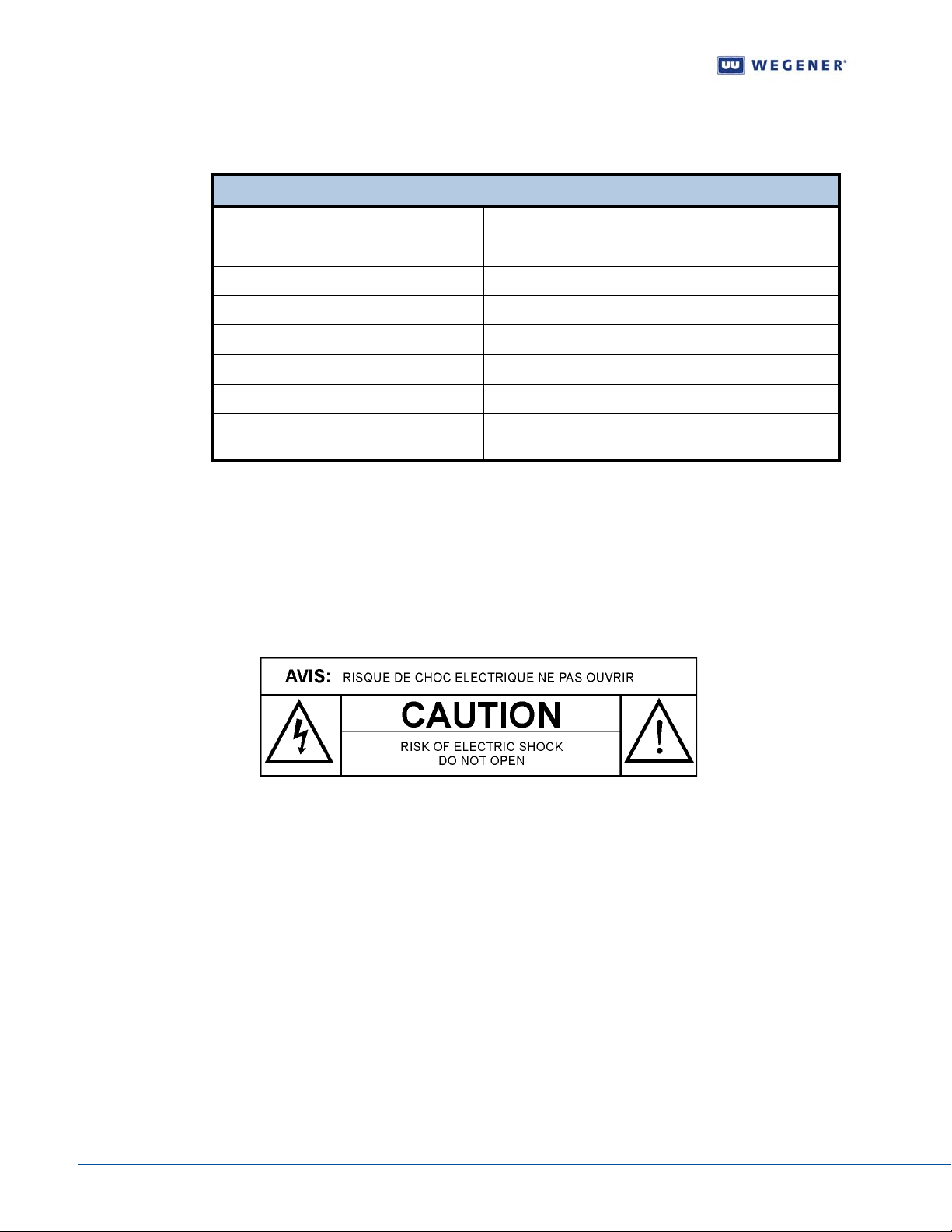
1.4 Safety Summary
The iPump 562 is designed for safe use with few special precautions required of the user.
The following items are basic precautions to use when installing and working with the
iPump 562 unit:
Do not open the iPump 562's chassis cover.
The iPump 562 incorporates security labels over some of the screws. There are no user
serviceable components within the IRD. Tampering with the security labels, or opening the
unit, will void your warranty. If you have questions, contact the
Support Department
Service, of this manual.
WEGENER Customer
at the address or phone (fax) numbers listed in Chapter 5 Customer
10 800092-01 Rev. A www.wegener.com
Page 21

CHAPTER 2 INSTALLATION
This chapter provides instructions on unpacking, mounting, and connecting your iPump 562
as well as connector information including detailed pinouts.
2.1 Unpacking and Inspection
Carefully unpack the unit and its ac power cord and inspect for obvious signs of physical
damage that might have occurred during shipment. Any damage claims must be reported to
the carrier immediately. Be sure to check the package contents carefully for important
documents and materials.
Note: Please save the packing materials and original shipping containers in case you
must later return the unit for repair . Packing these units in other containers in such a
way that they are damaged will void your warranty.
2.2 Location and Mounting
Unity 552 User’s Manual
The iPump 562 may be mounted in a standard 1 9-inch equipment rack or set up for desktop
operation. In either location, maintain a clean, dry environment for the
Precautions FCC-Mandated Suppression of Radio Frequency Emissions
WARNING
DANGER
This is a Class A product. In a domestic environment this product may cause radio
interference for which the user may need to take mitigating action.
If the Ethernet port has a cable connected to it, that cable must be properly shielded and
grounded to minimize RF emissions that could interfere with nearby equipment.
To avoid damage to the iPump 562 unit and other equipment, or personal injury, the
following items should be strictly observed.
Elevated Ambient Operating Temperatures in Rack-Mounted Units
When equipment is installed in a closed or multi-unit rack assembly, the ambient operating
temperature of the rack environment may be greater than the room's ambient temperature.
Therefore, consideration should be given to the ambient air temperature within the rack (not
just inside the room) when deciding if the maximum recommended ambient operating
temperature (TMRA) is met or exceeded.
Reduced Air Flow
Equipment should be installed such that the airflow required for safe operation of the
equipment is not compromised. The
spaces between units, if heat buildup is prevented by ensuring that the side vents remain
unblocked, and that there is adequate clearance around the vent holes.
iPump 562 may be arranged in a rack without empty
iPump 562.
Mechanical Loading
Rack-mounted equipment should be installed in such a way that a hazardous condition is
not produced by uneven loading. The
www.wegener.com 800092-01 Rev. A 11
iPump 562 unit is not very heavy, but total rack
Page 22

Installation
loading must be considered. Also, do not rest any unsupported equipment on a rackmounted
iPump 562 unit.
Circuit Overloading
Consideration should be given to the connection of the equipment to the supply circuit and
the effect that overloading of circuits could have on overcurrent protection and supply
wiring. Ensure that the total rack or breaker power consumption does not exceed the limits
of the AC branch circuit. Appropriate consideration of equipment ratings should be used
when addressing this concern.
Reliable Earthing
When connecting the iPump 562 unit to the power supply, review the ratings of all
equipment in the circuit to ensure that the branch circuit, as well as the power source, will
not be overloaded. Also make sure that the unit is p roperly grounded and/or tha t a protected
power strip is used to attach it to the power supply
Rack Mounting
The iPump 562 unit should be installed in such a way that a half-inch clearance is allowed
on each side and a quarter-inch on the top to ensure adequate air flow. Ensure that a
hazardous condition is not produced by uneven loading, or by resting any unsupported
equipment on a rack-mounted
iPump 562 unit.
Parts for the iPump 562 unit include 2 angle rack mount bracket s and 4 rubber feet. For ra ck
mounting, do not attach the rubber feet as they interfere with the rack mounting.
1. Remove the 2 screws from the left and right sides of th e unit.
2. Insert the angle brackets into the left and right sides of the unit ensuring that the
screw holes for the unit and brackets are aligned.
3. Secure the brackets by re-inserting the screws through the brackets and unit.
4. Install the unit onto the rack.
Note: The front brackets must be secured to the rack. If the front brackets are left
unsecured, the unit may shift forward and fall from the rack, and may result in
personal injury and/or damage to the equipment. The internal tempera ture of the
rack should not exceed 40
o
C.
Desktop Installation
Parts for the iPump 562 unit include 2 angle rack mount brackets and 4 rubber feet. For
desktop installation, do not attach the brackets.
1. Attach the 4 rubber feet onto the indented areas at the bottom of the unit.
2. Place the unit on a flat surface where it will not be subject to spills or impacts.
3. Route cables to the unit so that they will not be hit or pulled, causing damage to the
connectors or to the unit itself. Ensure a sufficient flow of cool air so that the unit's
operating ambient temperature range is not exceeded.
12 800092-01 Rev. A www.wegener.com
Page 23
CHAPTER 3 OPERATION
This chapter provides information and procedures for powering up, operating the unit,
upgrading software and tracking alarm conditions. Informa tion on four-port RF option and
Universal LNB Power is also presented.
3.1 Controlling and Monitoring
The IRD can be controlled via Compel network, front-panel using push-buttons and OSD
(On-Screen Display) or LCD menus or the diagterm ter minal using commands. The
is generally the primary method of controlling an IR. See the
explanation.
Unity 552 User’s Manual
Compel
Compel Manual for a complete
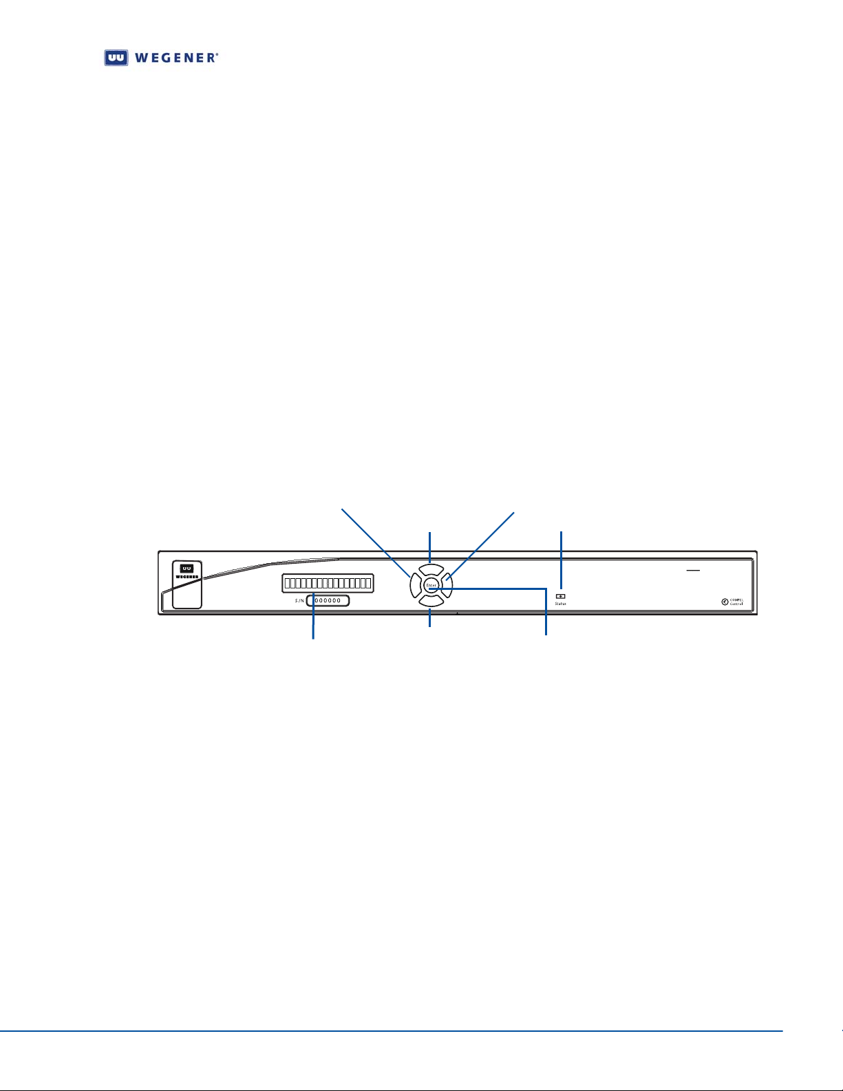
Front Panel Controls And Indicators
The iPump 562 is set up at the factory. However, you can customize the settings to fit your
system using the front-panel push-buttons and LCD screens or OSD menus. You may also
view those settings and various status information using the front-panel LCD, LED or OSD
screens.
Figure 3.1: iPump 562 Front Panel
left arrow button
top arrow button
bottom arrow button
LCD screen
right arrow button
LED
Enter button
iPump 562
Digital Media Server
LCD
Normally, the LCD on the front-panel displays Unit label and currently tuned channel
parameters for information. Pressing
Enter on the front-panel activates the LCD backlight.
When the OSD menu is active, the LCD on the front-panel displays the OSD item currently
selected. When certain status conditions, such as loss of signal occur, the LCD
automatically gets activated with illuminated backlight and displays relevant information on
the condition.
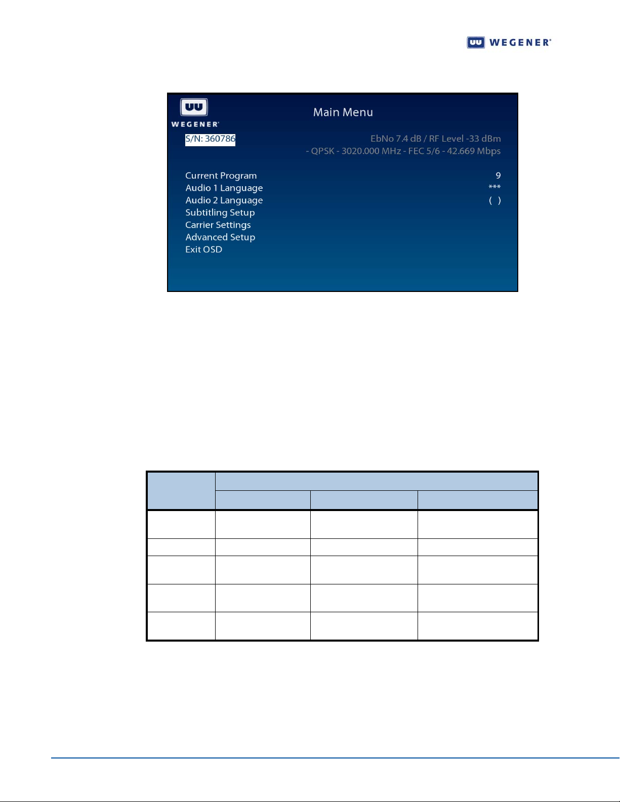
OSD
The On-Screen Display (OSD) menus are used to configure se ttings or monitor the st atus of
the IRD. The OSD information displays white text on blue background overlying 80% of the
video output viewed on a monitor connected to any of the video ports. The OSD screens are
activated (displayed on video monitor) and the menus can be navigated using the pushbuttons on the front-panel. On menus, a selected item is displayed with black text on white
background. Following example represents on e of th e OSD menus av ailabl e on
www.wegener.com 800092-01 Rev. A 13
iPump 562.
Page 24
Operation
Figure 3.2: OSD Main Menu
Push-buttons
Use the arrow buttons and Enter on the front panel to navigate and edit the fields on LCD
and OSD menus. Any of the push buttons activate OSD and LCD. The arrow buttons are
used to navigate through menus and to eith er change or display items to set desired options
for the IRD. The
Enter button is generally used to select menu items on LCD and OSD
menus. Selectable fields allow you to change the whole parameter from pre-determined
options. Editable fields allow you to change each digit of the parameter. Once a field is
updated, you must select Activate and Exit on the sub menu and then press
the value of the field. Before pressing
Enter, you may go back to any field and correct it prior
Enter to update
to acceptance. The left arrow button usually steps back a menu.
Table 3.1: Menu Navigation using Push-buttons
Button
Enter selects submenu or
right arrow no action no action moves cursor to right
left arrow exits OSD goes to previous menu
up arrow goes to next or
down arrow goes to next or
Main Menu Submenu Edit Mode
goes to editable field accepts changes
drop-down list
level
goes to next or previous
previous menu item
previous menu item
menu item
goes to next or previous
menu item
Actions
moves cursor to left or
abandon changes
increases value of selected
item
decreases value of selected
item
LED
Upon power up, the IRD initializes all system components and supplies an operational
status. A steady Green LED indicates that it is locked on a carrier and is capable of
producing output (Audio/Video/Data).
In case of problems, the LED flashes Red for alarm conditions or Amber for warning
conditions. In general, alarms indicate that the unit cannot produce output, while Warnings
14 800092-01 Rev. A www.wegener.com
Page 25
Unity 552 User’s Manual
indicate that, although output is being produced, there is a problem that could require
attention. The most common conditions that produce alarms or warnings are listed in
3.2.
Table 3.2: iPump 562 Front Panel Status LED Alarm and Warning Indications
Mode LED Status Condition
Red blink = 2 No carrier
Red blink = 3 No RF signal
Table
Diagterm Terminal (Commands)
Alarm
Warning
Normal Green Normal operation
Red blink = 4 In recovery
Red blink = 5 Eb/No alarm
Red blink = 11 Not authorized
Amber blink = 1 No response from SEC_MICRO
Amber blink = 2 Marginal Eb/No
Amber blink = 4 Selected audio not available
Amber blink = 5 RF too low
Amber blink = 6 RF too high
Amber blink = 7 Application download failed
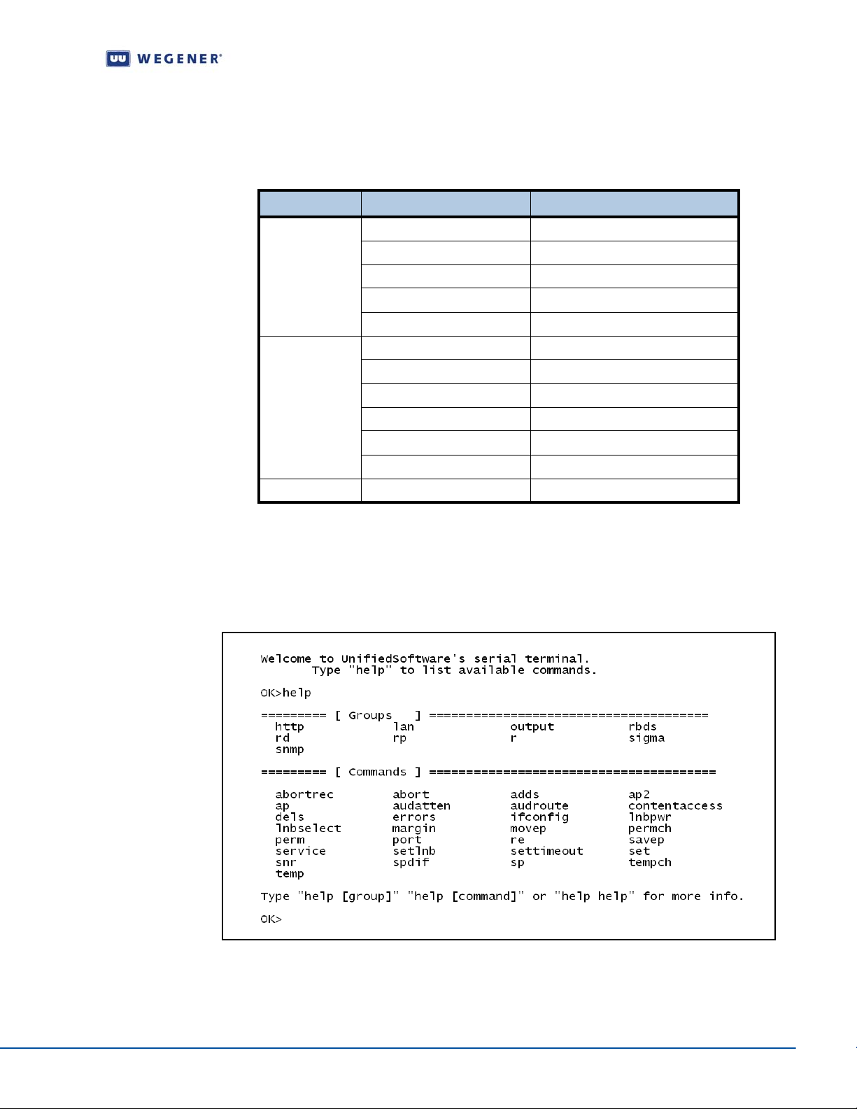
The Serial Port (RS-232) can be used to connect to a terminal console. After the IRD is
powered on, a diagterm command-line interface (CLI) can be used to monitor and control
the system. For more information on diagterm and syntax of the individual commands,
please see an appendix.
Figure 3.3 illustrates the Help screen on the diagterm terminal.
Figure 3.3: Diagterm Terminal Help Screen
www.wegener.com 800092-01 Rev. A 15
Page 26

Operation
Compel™ System Control
The iPump 562 IRD is most often controlled via the WEGENER Compel Control System.
This system is managed at the uplink site, sending a control stream with the usual audio
and video data streams. The
perform various functions.
Among its functions is the ability to enable or limit aspects of local control. Also, Compel has
the ability to mute the audio and video of an IRD if it is inadvertently tuned to a frequency it
is not authorized to receive.
If an RF Switch option module is installed, Compel controls which of the four RF feeds is
being processed. For more information on this, see the
service provider.
There are four levels of control via Compel. These levels are:
No Local Control - Push-buttons disabled
Read Only - No changes permitted
Limited - Changes may be made to Carrier Presets (pre-loaded values) only
Full - Full Local Control
3.2 Normal Functions
The iPump 562 allows several functions for basic operation and optimum perf or m an ce .
Tune to a carrier
Configure LNB options
Monitor Signal Quality
Set Subtitling
Configure operating options:
Set Decoder options
Setup Audio
Set LAN IP Networking options
Set Terminal options
Set Printer options
Set User Relay
Set Date and Time information
Set Unit Label
Switch Application (to different software version)
Monitor status information:
View Signal Quality
Query Networking History
Display LAN IP Network information
Find Software Version information
Clear Statistics used for diagnosis
Play out play lists of media files
Compel System addresses units, and commands them to
Compel Manual, or contact your
The functions listed above are illustrated below with instructions, OSD screens and other
relevant information.
16 800092-01 Rev. A www.wegener.com
Page 27
Unity 552 User’s Manual
Tune to a carrier
Carrier Settings screen
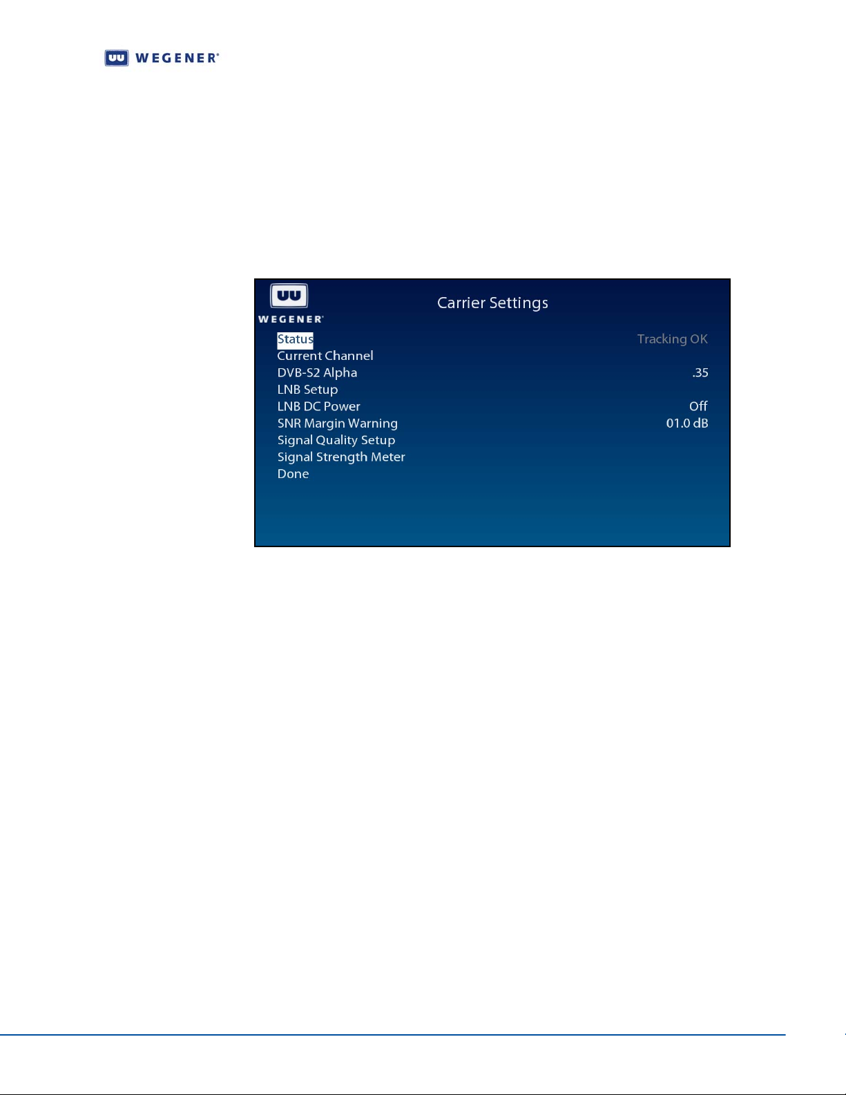
Use following steps to display Carrier Settings screen on the OSD menu:
1. Press any push-button on the front-panel to display the Main Menu.
2. Press the down arrow button to select Carrier Settings.
3. Press Enter.
4. View the details as shown in Figure 3.4.
Figure 3.4: iPump 562 OSD Carrier Settings Screen
Notes:
The Status shall be displayed as Tracking OK if the unit is tuned to a carrier.
Valid values for DVB-S2 are 0.35, 0.25 and 0.20.
The LNB DC Power may be turned on or off.
The SNR Margin Warning may be set with a desired threshold value in dB.
Current Channel screen
Use following steps to display Current Channel screen on the OSD menu:
1. From the Carrier Settings screen, press the down arrow button to select Current
Channel
.
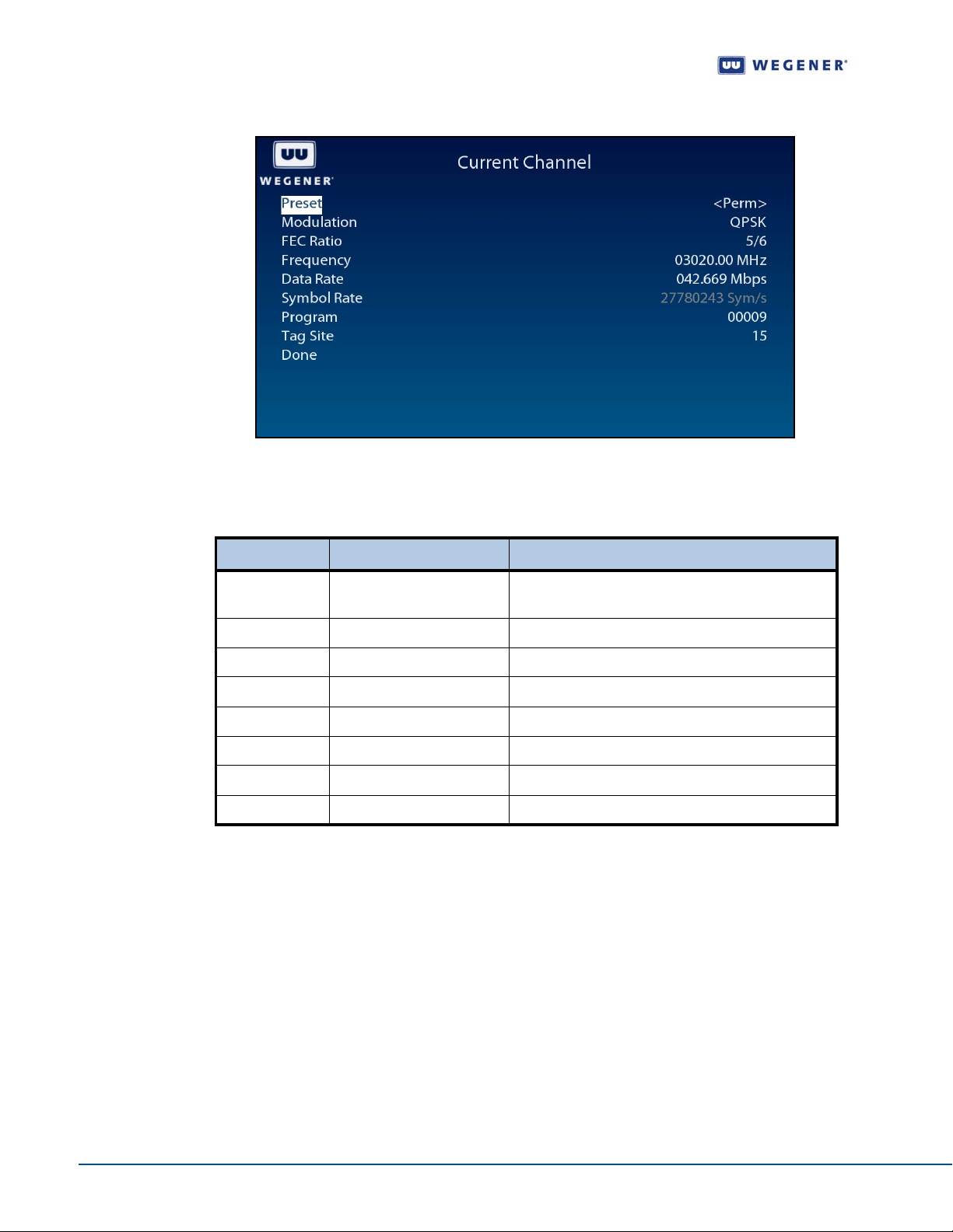
2. Press Enter to display the Current Channel screen shown in Figure 3.5.
3. To navigate the screen, use the down arrow and Enter buttons to select an option.
When the corresponding value of that option on the left is selected, use up or down
buttons to set to the desired setting. Press
Enter when done. Move to the next
option using up or down button or left arrow to exit to the previous menu level.
www.wegener.com 800092-01 Rev. A 17
Page 28
Operation
Figure 3.5: iPump 562 OSD Current Channel Screen
Use the Current Channel screen to set or display the channel information.
Configure LNB options
Table 3.3: Channel Information Options
Option Possible values Comments
Preset Perm, Command, Last
Success or Current
Modulation QPSK/S2QPSK/S28PSK -
FEC Ratio 1/2, 2/3, ¾, 5/6, 7/8 -
Frequency
Data Rate
Symbol Rate Automatically calculated and displayed only
Program Set to the desired program # in the carrier
Tag Site The tag #15 is a special value
Only Perm option allows other options to be set.
The channel set using the Compel Command.
LNB Setup screen
Use following steps to display LNB Setup screen on the OSD menu:
1. Press any push-button on the front-panel to display the Main Menu.
2. Press the down arrow button to select Carrier Settings.
3. Press Enter.
4. Press the down arrow button to select LNB Setup.
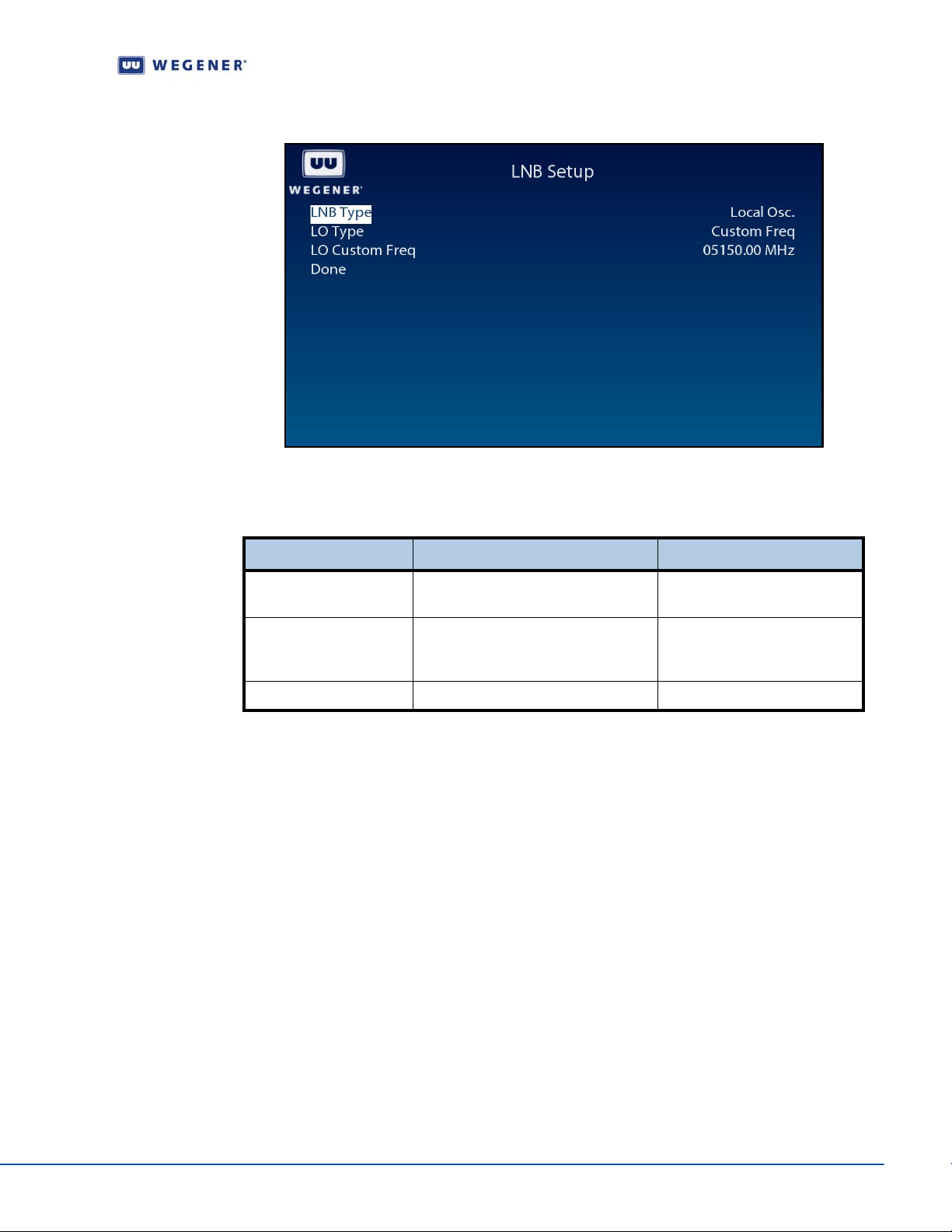
5. Press Enter. Figure 3.6 details the LNB Setup screen.
6. To navigate the screen, use down arrow and Enter to select an option. When the
corresponding value of that option on the left is selected, use up or down buttons to
set to the desired setting. Press
Enter when done. Move to the next option using up
or down button or left arrow to exit to the previous menu level.
18 800092-01 Rev. A www.wegener.com
Page 29
Unity 552 User’s Manual
Figure 3.6: iPump 562 OSD LNB Setup Screen
Use the LNB Setup screen to set and display the LNB configuration.
Monitor Signal Quality
Table 3.4: LNB configuration options
Option Possible values Comments
LNB Type Local Oscillator or Universal/ASTRA Only Local Osc option allows
other options to be set.
LO Type Custom Freq., Std C-band, US Ku-
band, Euro Low Ku-band or Euro Hi
Ku-band
LO Custom Freq.
Only Custom Freq. option
allows other options to be set.
Signal Quality Setup screen
Use following steps to display Signal Quality Setup screen on the OSD menu:
1. Press any push-button on the front-panel to display the Main Menu.
2. Press the down arrow button to select Carrier Settings.
3. Press Enter.
4. Press the down arrow button to select Signal Quality Setup.
5. Press Enter to display the Signal Quality Setup screen shown in Figure 3.7.
www.wegener.com 800092-01 Rev. A 19
Page 30
Operation
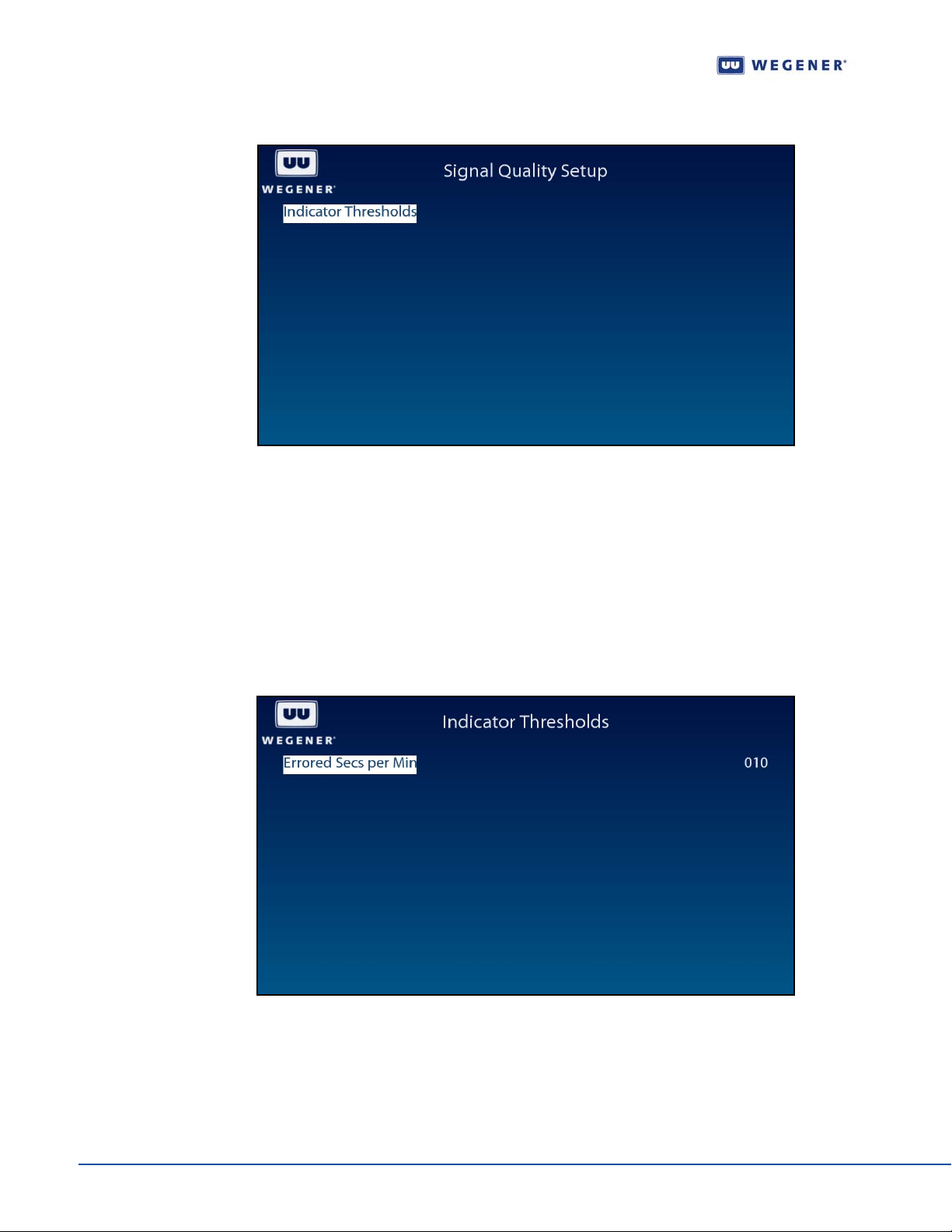
Figure 3.7: iPump 562 OSD Signal Quality Setup Screen
Indicator Threshold screen
Use following steps to display the Indicator Threshold screen on the OSD menu:
1. From the Signal Quality Setup screen, ensure that Indicator Thresholds is selected.
2. Press Enter to display the Indicator Threshold screen shown in Figure 3.5.
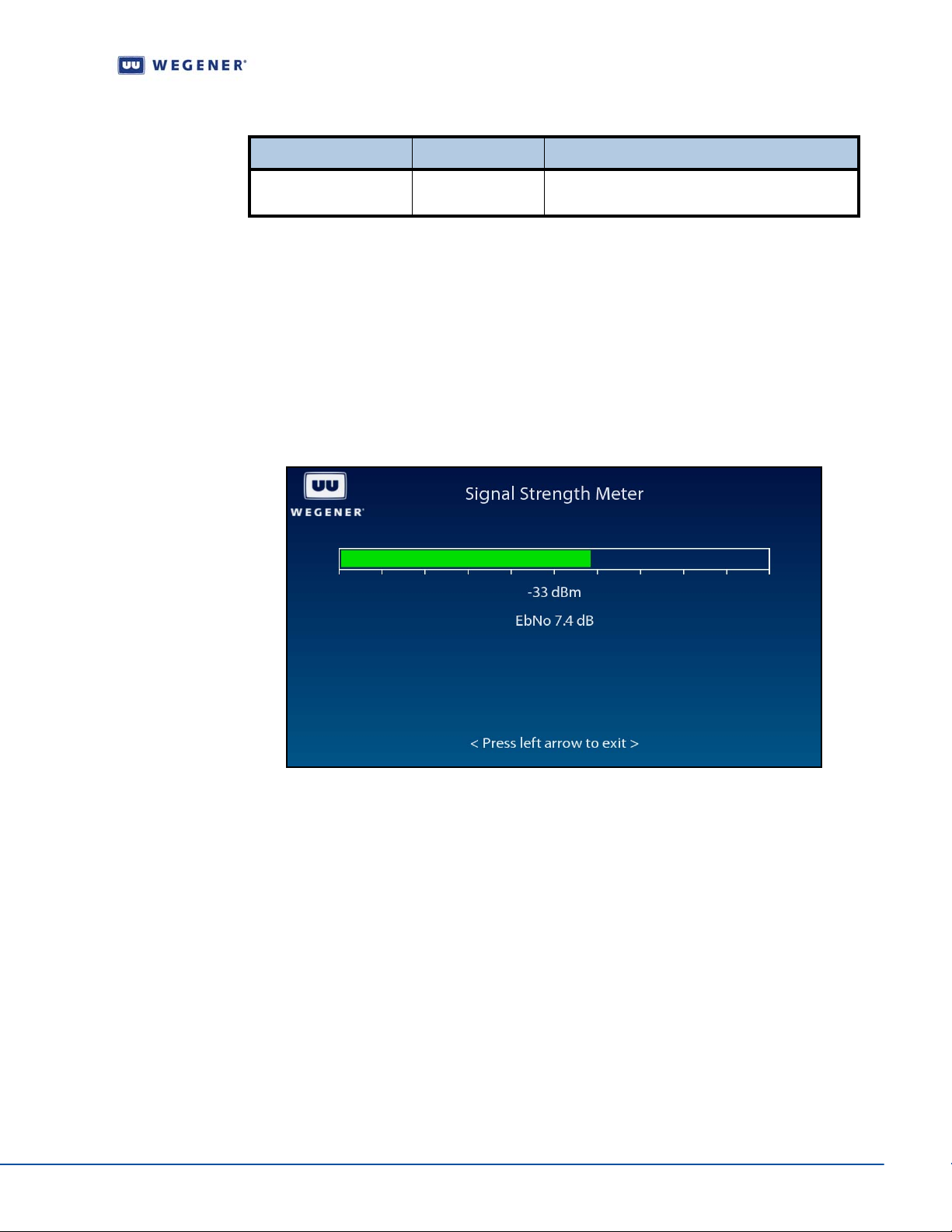
3. To navigate the screen, press Enter to hig hlight the valu e. Use up or down buttons to
set to the desired setting. Press
Enter when done. Use left arrow to exit to the
previous menu level.
Figure 3.8: iPump 562 OSD Indicator Threshold Screen
Use the Indicator Threshold screen to set and display the warning condition.
20 800092-01 Rev. A www.wegener.com
Page 31
Unity 552 User’s Manual
Table 3.5: Indicator Threshold screen options
Option Possible values Comments
Errored Secs per Min 10 to 19 Set the threshold for how many errors per
minutes before raising a warning condition.
Signal Strength Meter screen
Use following steps to display Signal Strength Meter screen on the OSD menu:
1. Press any push-button on the front-panel to display the Main Menu.
2. Press the down arrow button to select Carrier Settings.
3. Press Enter.
4. Press the down arrow button to select Signal Strength Meter.
5. Press Enter to view the screen as shown in Figure 3.9.
Figure 3.9: iPump 562 OSD Signal Strength Meter Screen
Set Subtitling options
Subtitling Setup screen
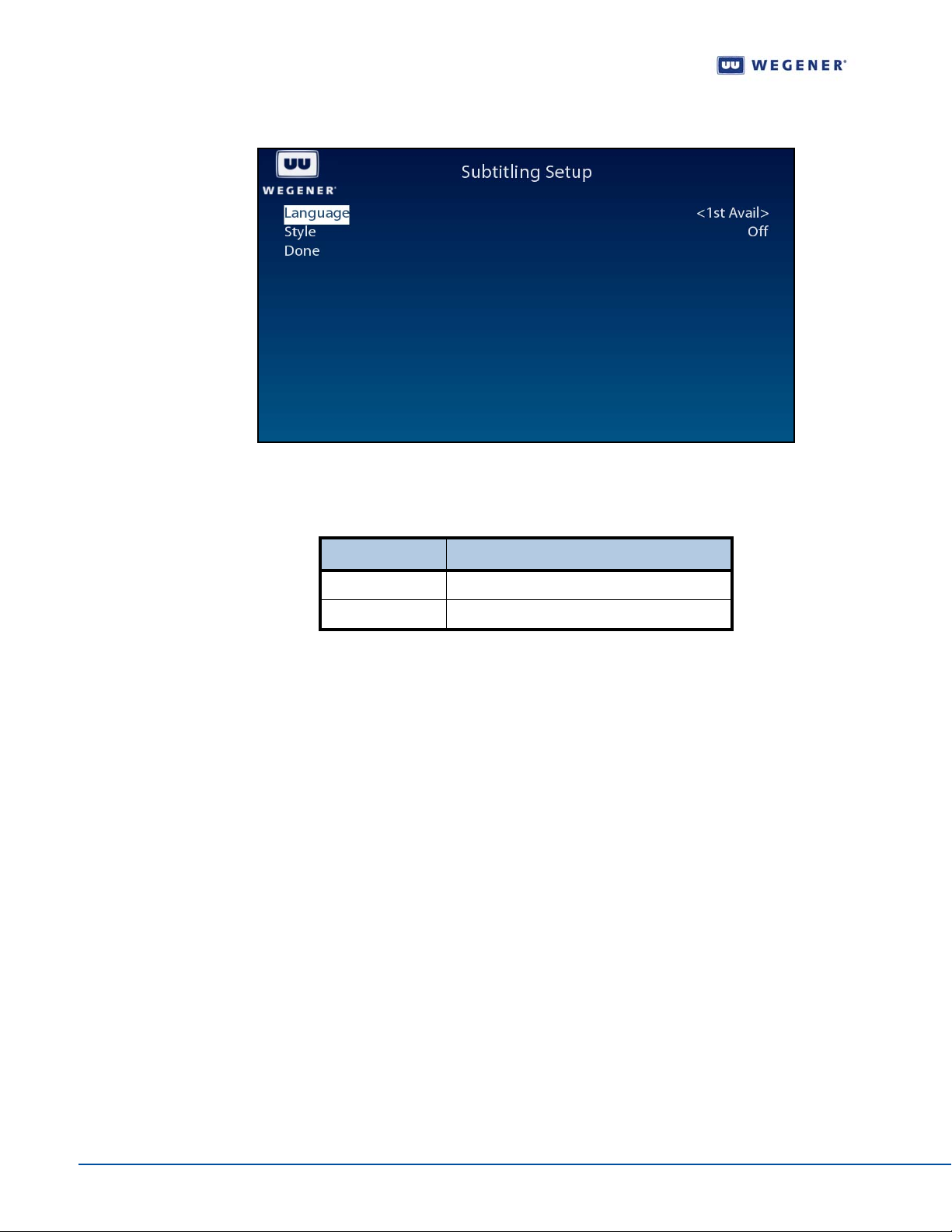
Use following steps to display Subtitling Setup screen on the OSD menu:
1. Press any push-button on the front-panel to display the Main Menu.
2. Press the down arrow button to select Subtitling Setup.
3. Press Enter.
4. View the details as shown in Figure 3.10.
www.wegener.com 800092-01 Rev. A 21
Page 32
Operation
Figure 3.10: iPump 562 OSD Subtitling Screen
Use the Subtitling Setup screen to set and display the Subtitling information.
Configure the unit for operation
Table 3.6: Subtitling Setup screen options
Option Possible values
Language English, French, Spanish or 1st Available
Style Normal, Normal + Captioning or Off
Advanced Setup screen
Use following steps to display Advanced Setup screen on the OSD menu:
1. Press any push-button on the front-panel to display the Main Menu.
2. Press the down arrow button to select Advanced Setup.
3. Press Enter.
4. View the details as shown in Figure 3.11.
22 800092-01 Rev. A www.wegener.com
Page 33
Unit Setup screen
Unity 552 User’s Manual
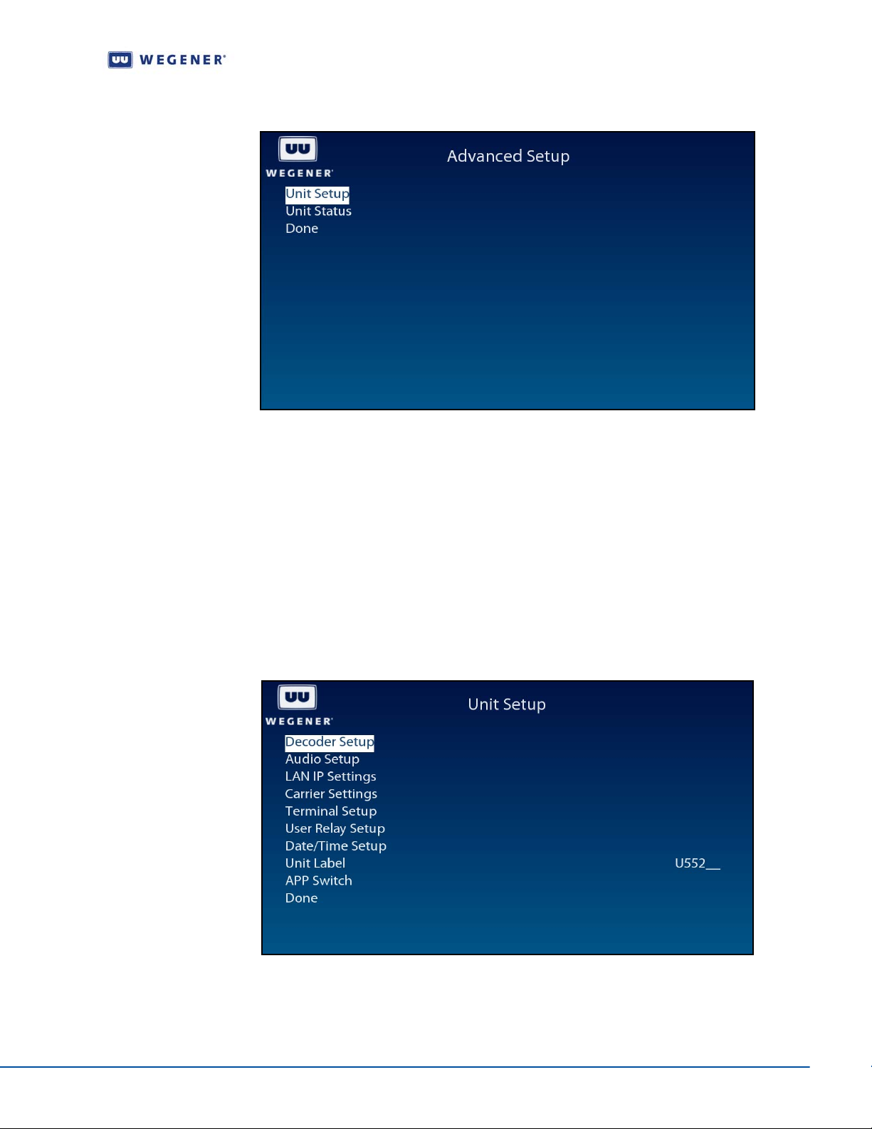
Figure 3.11: iPump 562 OSD Advanced Setup
Use following steps to display Unit Setup screen on the OSD menu:
1. Press any push-button on the front-panel to display the Main Menu.
2. Press the down arrow button to select Advanced Setup.
3. Press Enter.
4. Press the down arrow button to select Unit Setup.
5. Press Enter.
6. View the details as shown in the Figure 3.12.
Figure 3.12: iPump 562 OSD Unit Setup
The following options are available for setting the unit for operation:
Decoder Setup
Audio Setup
www.wegener.com 800092-01 Rev. A 23
Page 34
Operation
LAN IP Networking
Carrier Settings
Terminal options
User Relay
Date and Time information
Unit Label settings
Switch Application
Set Video Decoder options
Set Decoder Options
Use following steps to display Decoder Setup screen on the OSD menu:
1. Navigate to the Unit Setup screen, see Unit Setup screen on page 23.
2. Press the down arrow button to select Decoder Setup.
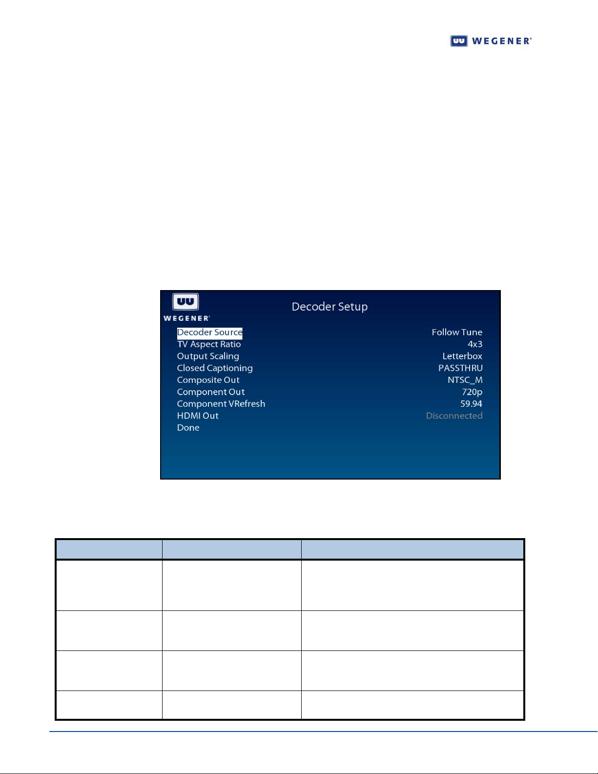
3. View the details as shown in Figure 3.13.
Figure 3.13: iPump 562 OSD Decoder Setup
Use the Decoder Setup screen to set and display the decoder options.
Table 3.7: Video Decoder Options
Option Possible values Comments
Decoder Source Follow Tune (currently selected
RF source and program #) or Off
(no A/V output)
TV Aspect Ratio 4x3 (Traditional TV) 16x9 (Wide
screen TV) 14x9 (CiniView II)
Output Scaling Letterbox (black bars either at
top/bottom or at sides), Pan/Scan
(display may be off screen)
Closed Captioning PASSTHRU (ntsc/pal) or CC1:4
(EIA-608) orDTV (EIA-708-B)
24 800092-01 Rev. A www.wegener.com
Controls source of input transport stream for the
primary A/V decoder to play. The source can be either
Multicast UDP from Satellite/RF or Multi/Unicast UDP
from LAN/ETHERNET
Allows the receiver to automatically correct a mismatch
in the aspect ratio of the TV to the content being
displayed.
Optimizes viewing quality if the content does not match
the TV Aspect Ratio. In Pan/Scan mode, improvement
in viewing experience depends on the source content.
Sets the option to render subtitling information in
different formats including Divicom.
Page 35
Unity 552 User’s Manual
Option Possible values Comments
Composite Out NTSC_M, NTSC_J, PAL/50 or
PAL/60
Component Out 480i, 480p, 576i, 576p, 720p or
1080i
Component V-Refresh 50 or 60 or 59.94 Configures the video/vertical refresh rate
HDMI Out - Displays current display mode of the DVI/HDMI device
Selects video output format
Selects video output format. When a DVI/HDMI device
is connected, the mode shall be automatically set to
Slave.
after EDID negotiation.
Setup Audio
Use following steps to display Audio Setup screen on the OSD menu:
1. Navigate to the Unit Setup screen, see Unit Setup screen on page 23.
2. Press the down arrow button to select Audio Setup.
3. View the details as shown in Figure 3.15.
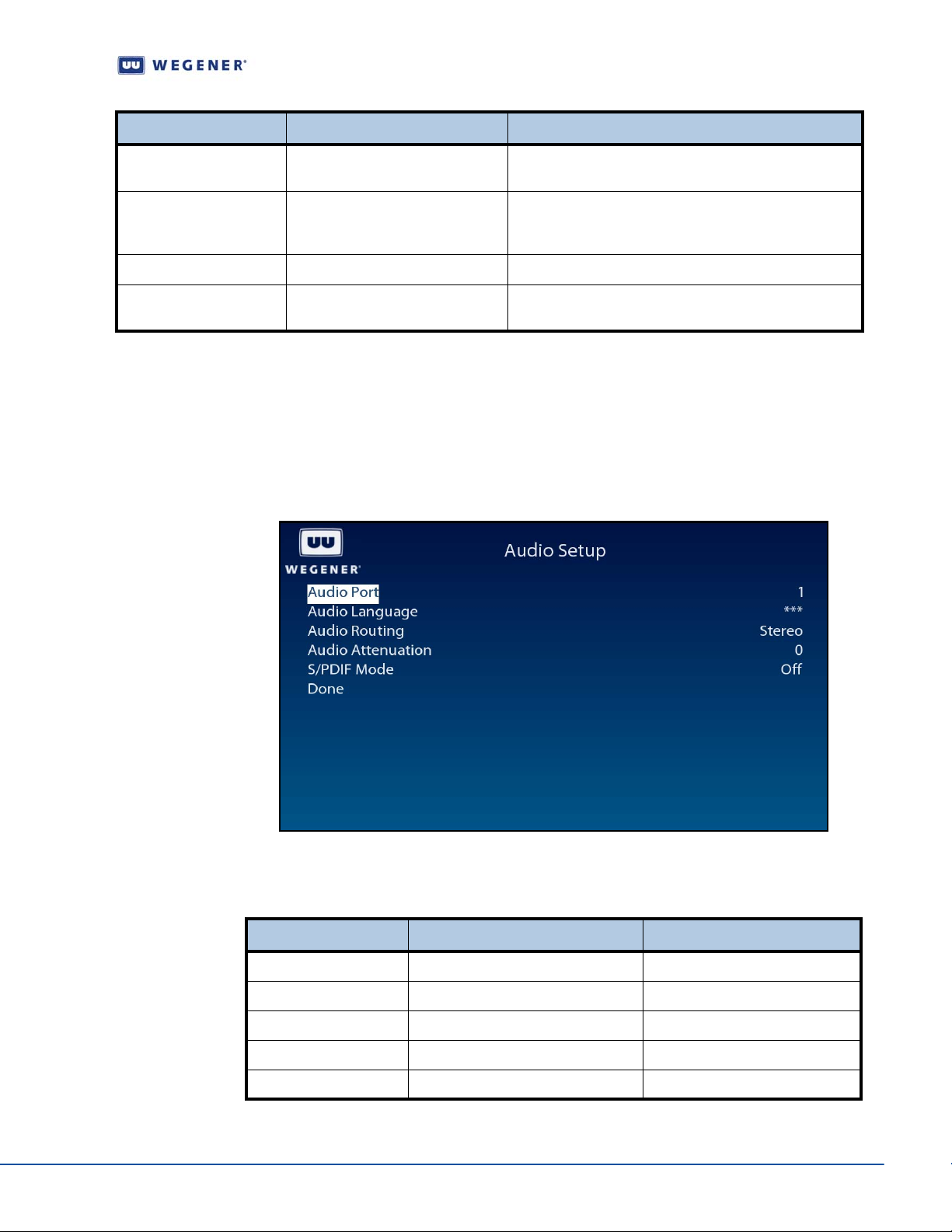
Figure 3.14: iPump 562 OSD Audio Setup
Use the Audio Setup screen to set and display the audio output options.
Table 3.8: Audio Output Options
Option Possible values Comments
Audio Port 1 or 2
Audio Language A01 or ***
Audio Routing Stereo or Left/Right on both May be used for two languages
Audio Attenuation 0 through 20
S/PDIF Mode Passthru, Linear PCM or Off
www.wegener.com 800092-01 Rev. A 25
Page 36
Operation
Set LAN-based Decode options
Use following steps to display Decoder Source screen on the OSD menu:
1. Navigate to the Decoder Setup screen
2. Press the up or down arrow buttons to select Decoder Source.
3. Press Enter.
4. Press the up or down arrow buttons to select either LAN-Multicast or LAN-Unicast.
5. Press Enter.
6. Select Activate Settings.
7. Press Enter.
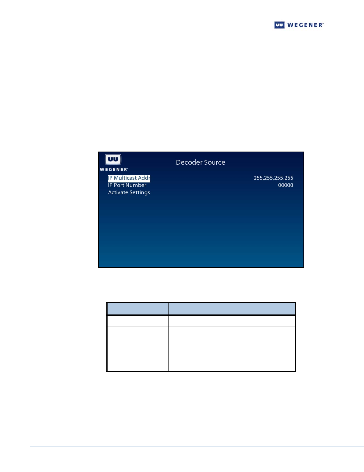
Figure 3.15: iPump 562 OSD Decoder Source
Use the Decoder Source screen to set and display the LAN Decode options.
Table 3.9: LAN Decode Options
Option Possible values
IP-Address Multicast or Unicast IP Address
IP-Port Number The corresponding IP Port number
Audio Routing Stereo or Left/Right on both
Audio Attenuation 0 through 20
S/PDIF Mode Passthru, Linear PCM or Off
Set LAN IP Networking options
Use following steps to display LAN IP Setup screen on the OSD menu:
1. Navigate to the Unit Setup screen, see Unit Setup screen on page 23.
2. Press the down arrow button to select LAN IP Setup.
3. View the details as shown in Figure 3.16.
26 800092-01 Rev. A www.wegener.com
Page 37
Unity 552 User’s Manual
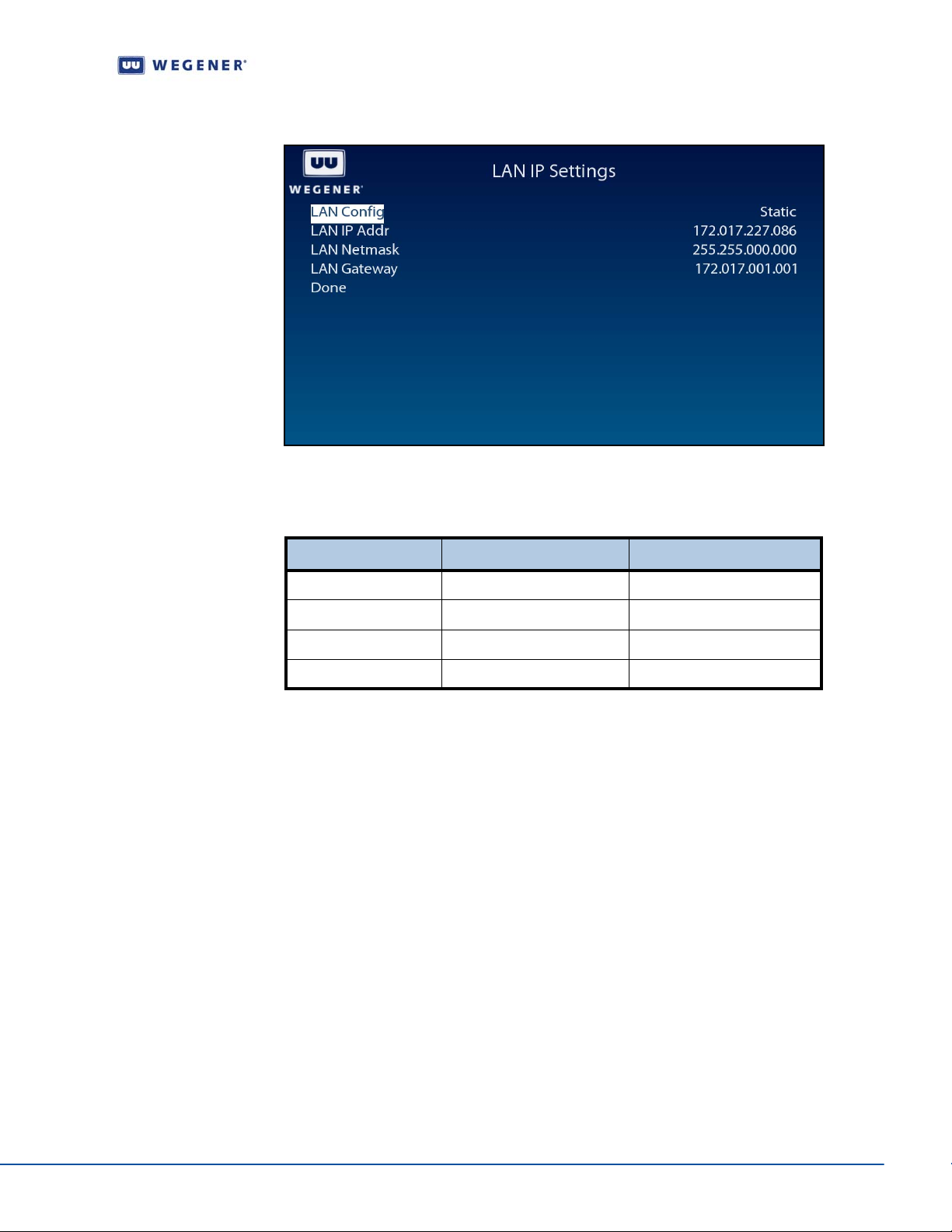
Figure 3.16: iPump 562 OSD LAN IP Setup
Use the LAN IP Setup screen to set and display the networking configuration.
Table 3.10: Networking Configuration Settings
Option Possible values Comments
LAN Configuration Static or DHCP
LAN IP Address - IP Address
LAN Netmask - IP Net-mask
LAN Gateway - IP Gateway Address
Set Terminal options
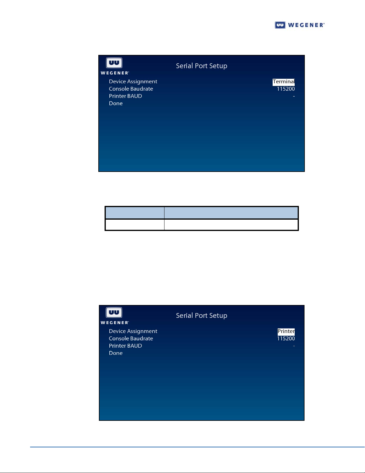
Use following steps to display Terminal Setup screen on the OSD menu:
1. Navigate to the Unit Setup screen, see Unit Setup screen on page 23.
2. Press the down arrow button to select Terminal Setup.
3. View the details as shown in Figure 3.17.
www.wegener.com 800092-01 Rev. A 27
Page 38
Operation
Figure 3.17: iPump 562 OSD Terminal Setup
Use the Terminal Setup screen to set and displa y the termin a l opt ion s.
Table 3.11: Terminal Options
Option Possible values
Console Baud-rate 2400, 9600, 19200, 38400, 57600, 115200
Set Printer Options
Use following steps to display Printer Setup screen on the OSD menu:
1. Navigate to the Unit Setup screen, see Unit Setup screen on page 23.
2. Press the down arrow button to select Printer Setup.
3. View the details as shown in Figure 3.17.
Figure 3.18: iPump 562 OSD Printer Options
28 800092-01 Rev. A www.wegener.com
Page 39
Unity 552 User’s Manual
Set User Relay
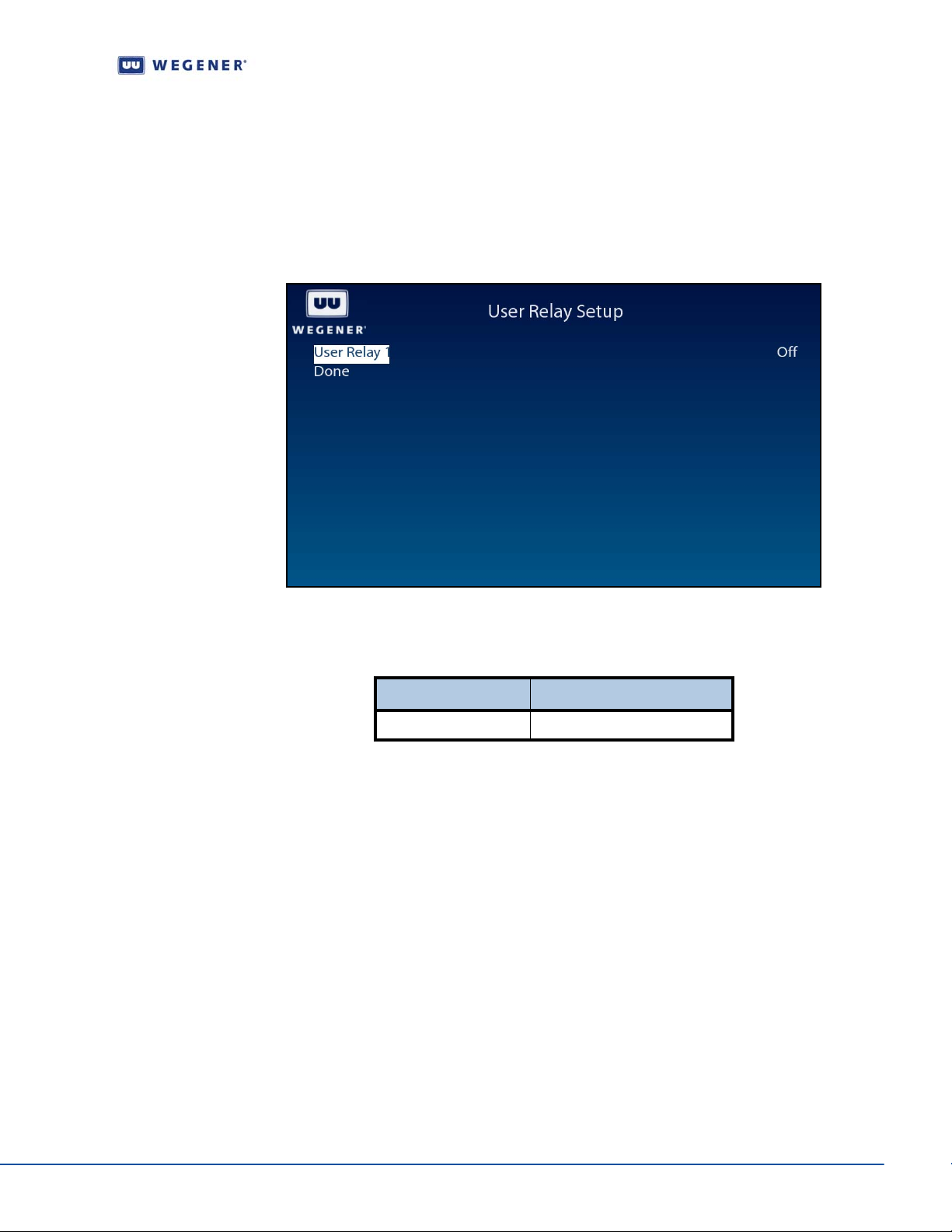
Use following steps to display User Relay Setup screen on the OSD menu:
1. Navigate to the Unit Setup screen.
2. Press the down arrow button to select User Relay Setup.
3. View the details as shown in Figure 3.19
Figure 3.19: iPump 562 OSD User Relay Setup
Use the User Relay Setup screen to set the User Relay Setup options.
Table 3.12: User Relay Setup Options
Option Possible values
User Relay 1 On/Off
Set Date and Time information
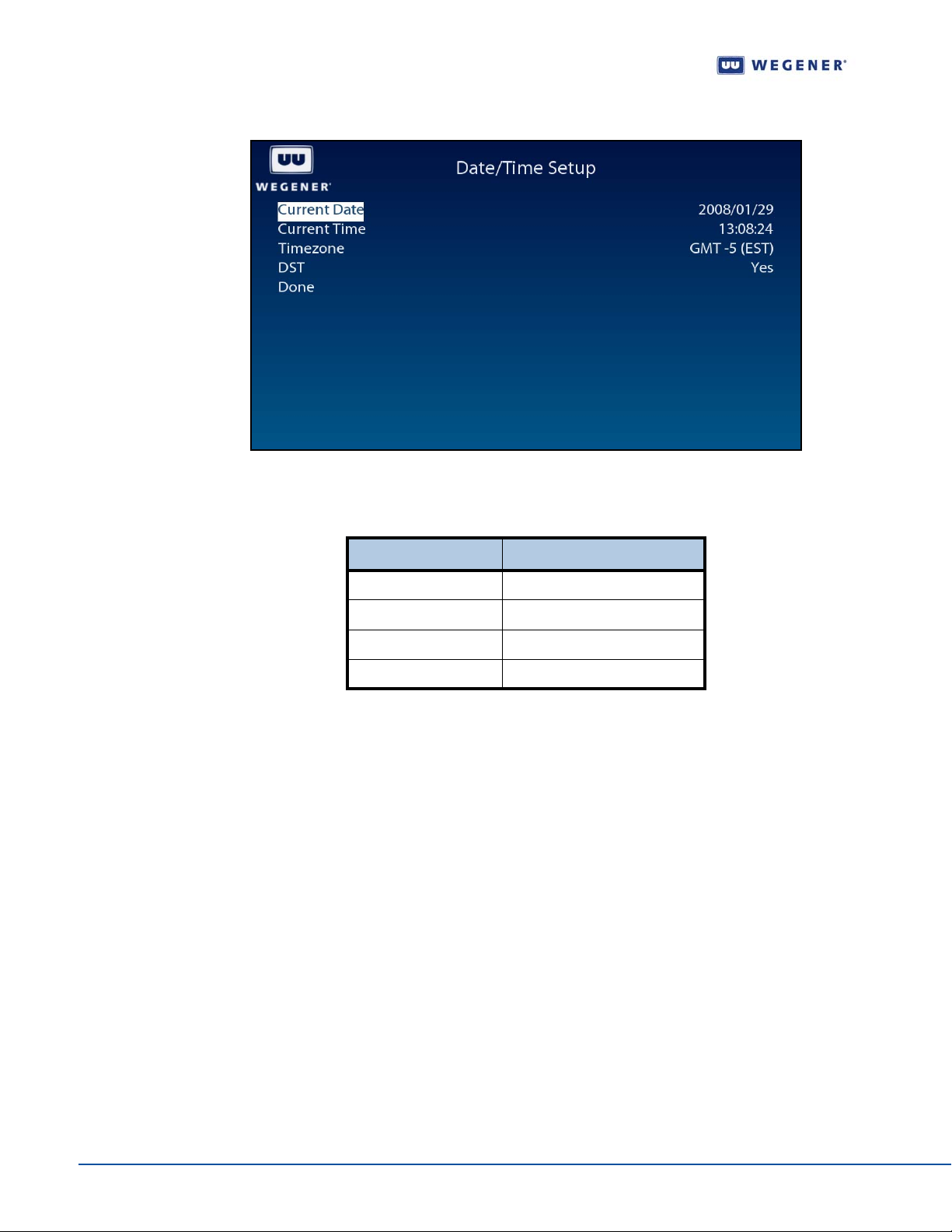
Use following steps to display Date/Time Setup screen on the OSD menu:
1. Navigate to the Unit Setup screen, see Unit Setup screen on page 23.
2. Press the down arrow button to select Date/Time Setup.
3. View the details as shown in Figure 3.19
www.wegener.com 800092-01 Rev. A 29
Page 40
Operation
Figure 3.20: iPump 562 OSD Date/Time Setup
Use the Date/Time Setup screen to set and display the date and time information.
Table 3.13: Date and Time Information Settings
Option Possible values
Current Date Yyyy/mm/dd
Current Time Hh:mm:ss
Time zone All available…
DST Yes / No
Set Unit Label
Use following steps to display Unit Label Setup screen on the OSD menu:
1. Navigate to the Unit Setup screen, see Unit Setup screen on page 23.
2. Press the down arrow button to select Unit Label.
3. Press Enter.
4. When the six-character label is selected, use the up/down and left/right buttons to set
to a desired label. Press
Enter to save the change. Use the left arrow button to go to
the previous menu level.
Switch Application (to different software version)
Use following steps to display Application Switch screen on the OSD menu:
1. Navigate to the Unit Setup screen, see Unit Setup screen on page 23.
2. Press the down arrow button to select Switch Application.
3. View the details as shown in Figure 3.21.
4. Use the Application Switch to run a backup version of the software on the unit. Upon
selecting the Backup Software by pressing
Enter, the system rest arts with the
different software which is labeled as current. The previously run software is labeled
30 800092-01 Rev. A www.wegener.com
Page 41

Unity 552 User’s Manual
backup. Use the Version Information screen to find out about the sof tware versions
installed in the system.
Figure 3.21: iPump 562 OSD Application Switch
Monitor Status Information
The following types of status information are available for viewing:
Signal Quality
Current Quality
History This Setting
Elapsed Times
Unit Status screen
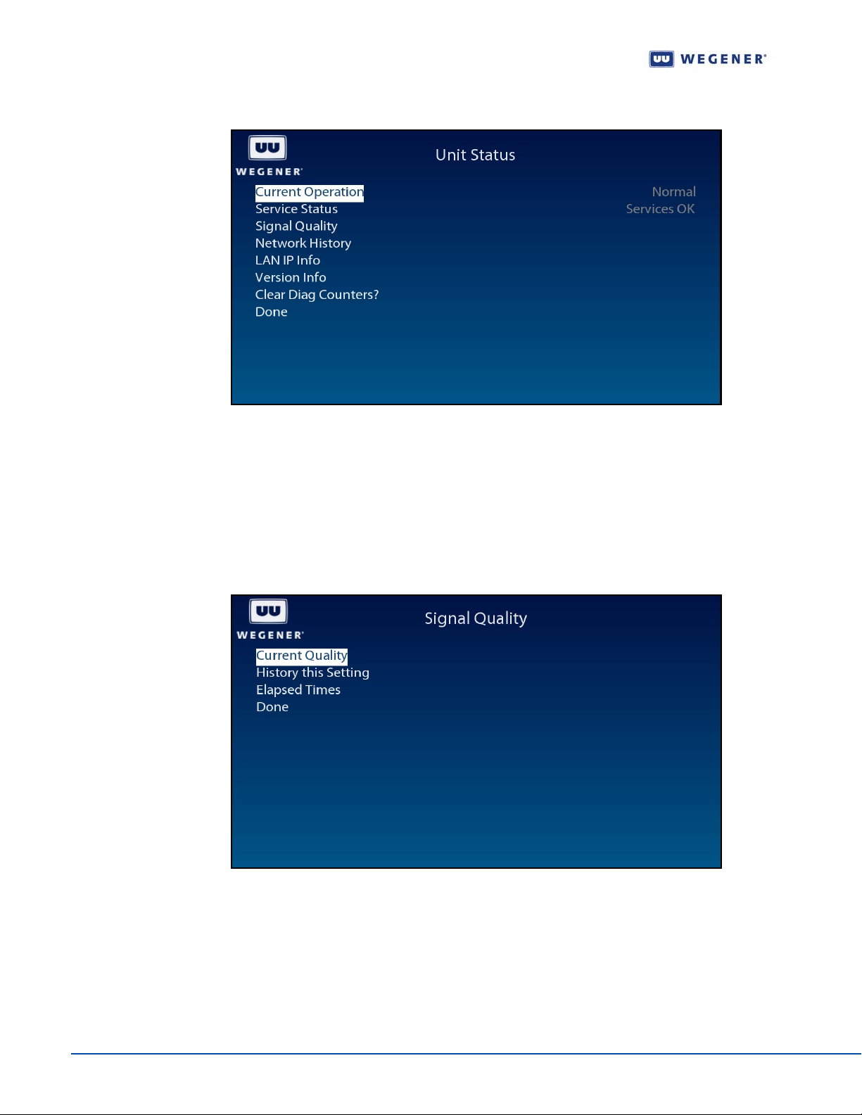
Use following steps to display the Unit Status screen on the OSD menu:
1. Press any push-button on the front-panel to display the Main Menu.
2. Press the down arrow button to select Advanced Setup.
3. Press Enter.
4. Press the down arrow button to select Unit Status.
5. Press Enter.
6. View the details as shown in Figure 3.22.
Note: When the unit is locked to a carrier and playing video/audio, the Current Operation
is Normal and Service Status is OK.
If carrier is not locked, Service Status can be Acquiring Transport.
www.wegener.com 800092-01 Rev. A 31
Page 42
Operation
Figure 3.22: iPump 562 OSD Unit Status
Signal Quality screen
Use following steps to display the Signal Quality screen on the OSD menu:
1. Navigate to the Unit Status screen, see Unit Status screen on page 31.
2. Press the down arrow button to select Signal Quality Status.
3. View the details as shown in Figure 3.23.
Figure 3.23: iPump 562 OSD Signal Quality Status
Current Quality screen
Use following steps to display the Current Quality screen on the OSD menu:
1. Navigate to the Signal Quality screen, see Signal Quality screen on page 32.
32 800092-01 Rev. A www.wegener.com
Page 43
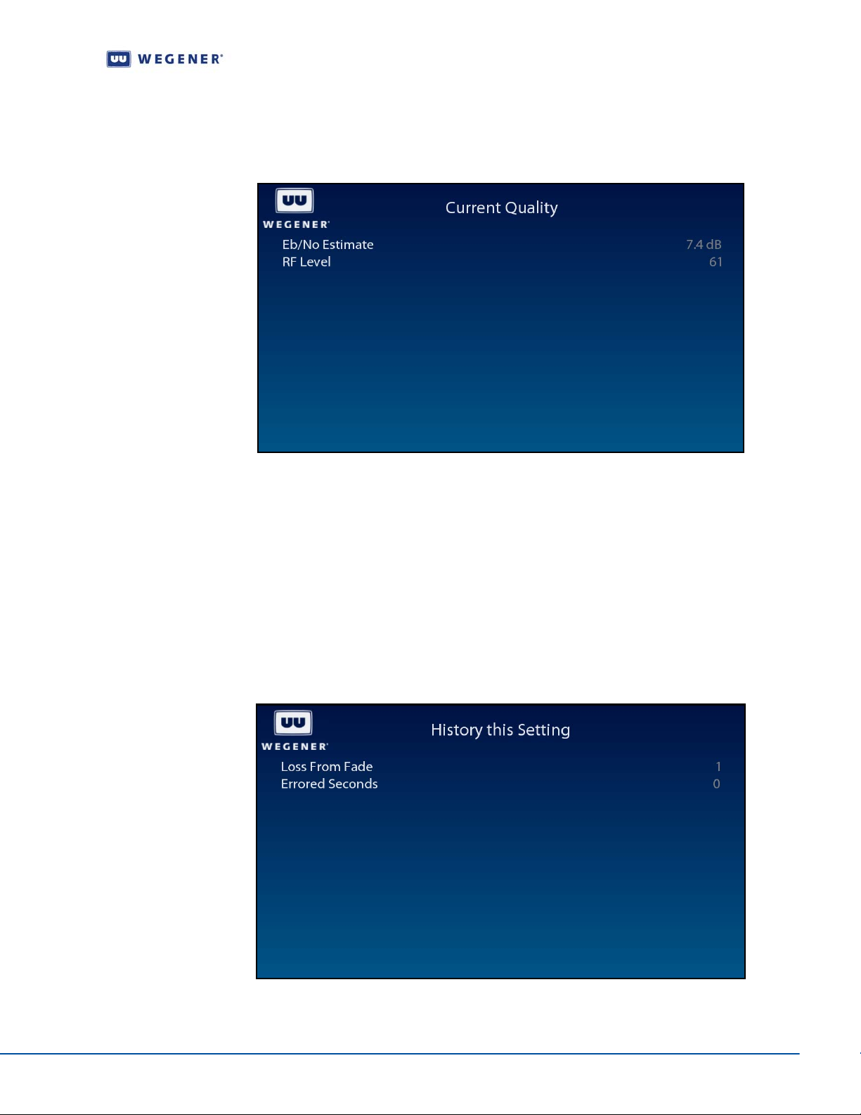
2. Press the down arrow button to select Current Quality.
3. View the details as shown in Figure 3.24.
Figure 3.24: iPump 562 OSD Current Quality
Unity 552 User’s Manual
History This Setting screen
Use following steps to display the History This Setting screen on the OSD menu:
1. Navigate to the Signal Quality screen. See Signal Quality screen on page 32
OR from a Signal Quality sub-screen, press the left arrow button to go back to the
Signal Quality screen.
2. Press the down arrow button to select History This Setting.
3. Press Enter.
4. View the details as shown in Figure 3.25.
Figure 3.25: iPump 562 OSD History This Setting
www.wegener.com 800092-01 Rev. A 33
Page 44
Operation
Elapsed Times screen
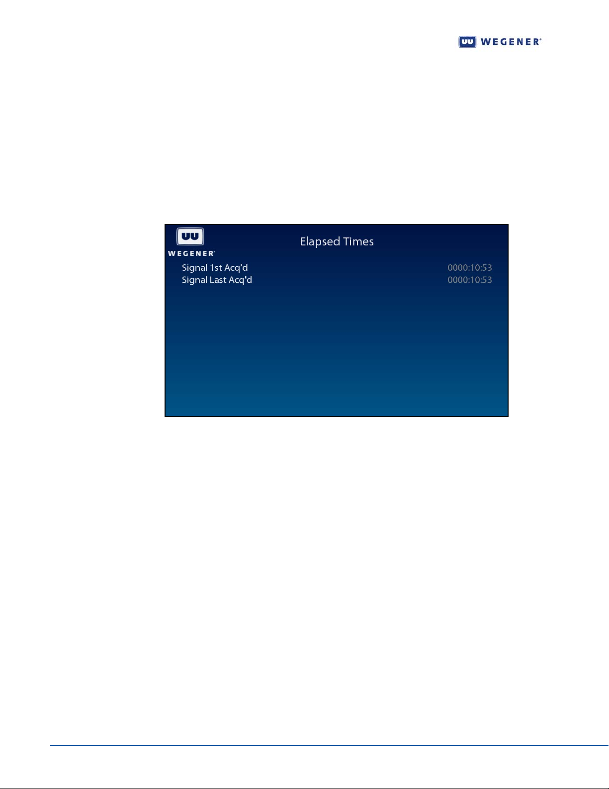
Use following steps to display the Elapsed Times screen on the OSD menu:
1. Navigate to the Signal Quality screen. See Signal Quality screen on page 32
OR from a Signal Quality sub-screen, press the left arrow button to go back to the
Signal Quality screen.
2. Press the down arrow button to select Elapsed Times.
3. Press Enter.
4. View the details as shown in Figure 3.26.
Figure 3.26: iPump 562 OSD Elapsed Times
Query Network History
Use following steps to display the Network History screen on the OSD menu:
1. Navigate to the Unit Status screen, see Unit Status screen on page 31.
2. Press the down arrow button to select Network History.
3. Press Enter.
4. View the details as shown in Figure 3.27.
34 800092-01 Rev. A www.wegener.com
Page 45
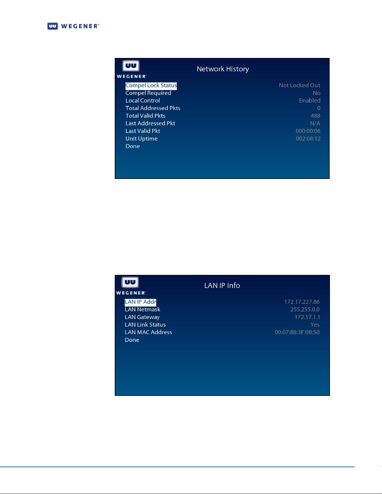
Figure 3.27: iPump 562 OSD Network History
Display LAN IP Network information
Unity 552 User’s Manual
Use following steps to display LAN IP Info screen on the OSD menu:
1. Navigate to the Unit Status screen, see Unit Status screen on page 31.
2. Press the down arrow button to select LAN IP Info.
3. Press Enter.
4. View the details as shown in Figure 3.28.
Figure 3.28: iPump 562 OSD LAN IP Info
Find Software Version information
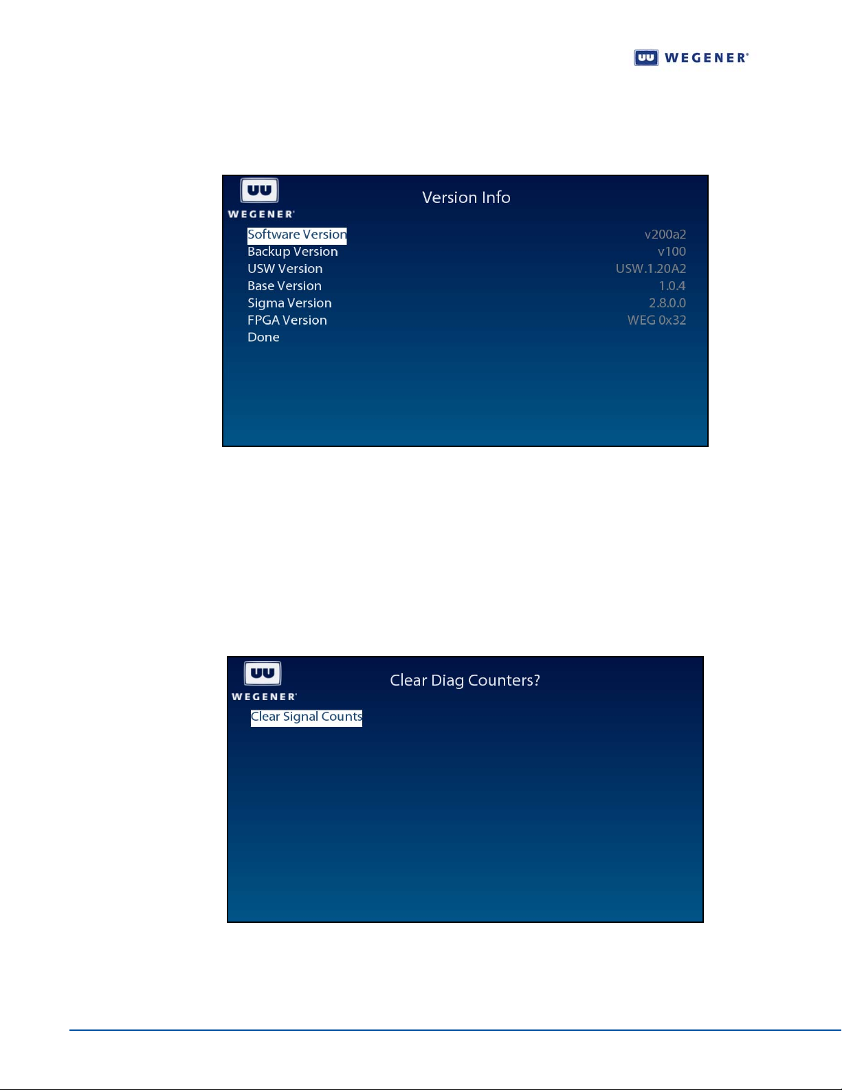
Use following steps to display Version Info screen on the OSD menu:
1. Navigate to the Unit Status screen, see Unit Status screen on page 31.
2. Press the down arrow button to select Version Info.
www.wegener.com 800092-01 Rev. A 35
Page 46
Operation
3. Press Enter.
4. View the details as shown in Figure 3.29.
Figure 3.29: iPump 562 OSD Version Info
Clear Statistics used for diagnosis
Use following steps to display Clear Signal Counters screen on the OSD menu:
1. Navigate to the Unit Status screen, see Unit Status screen on page 31.
2. Press the down arrow button to select Clear Signal Counters.
3. To reset the st atistical information for diagnosis, press Enter.
4. View the details as shown in Figure 3.30.
Figure 3.30: iPump 562 OSD Clear Signal Counters
36 800092-01 Rev. A www.wegener.com
Page 47
Unity 552 User’s Manual
Play out play lists of media files
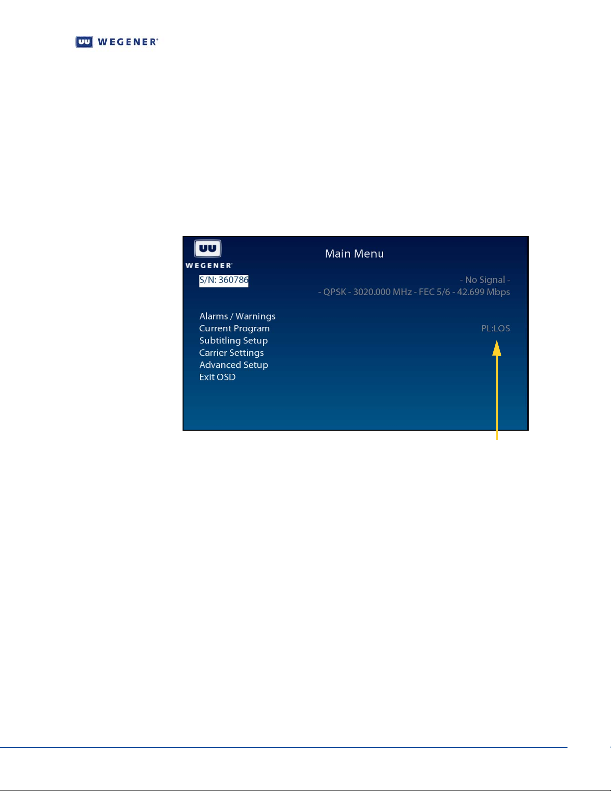
Play lists of media files can be sent to iPump 562 from Compel uplink using Assured Files
Delivery (AFD) for playing immediately upon receipt (Un-timed). The OSD
screen displays name of the play list currently being played under
Use following steps to display Play out play lists of media files screen on the OSD menu:
1. Navigate to the Unit Status screen, see Unit Status screen on page 31.
2. Press the down arrow button to select Clear Signal Counters.
3. To reset the st atistical information for diagnosis, press Enter.
4. View the details as shown in Figure 3.30.
Figure 3.31: iPump 562 OSD Clear Signal Counters
Current Program.
Main Menu
3.3 View Alarms/Warnings
Generally , the IRD functions by producing an Audio/V ideo/Dat a output. In some cases, such
as sudden loss of carrier , attempting to view an unauthorized program or RF level is too low,
an Alarm or Warning shall be generated. Usually, user intervention is necessary to resolve
an Alarm or a Warning. In addition to flashing the front-panel LED, more information can be
found using the OSD screens. A list of Alarms and Warnings can be found in
Controlling and Monitoring.
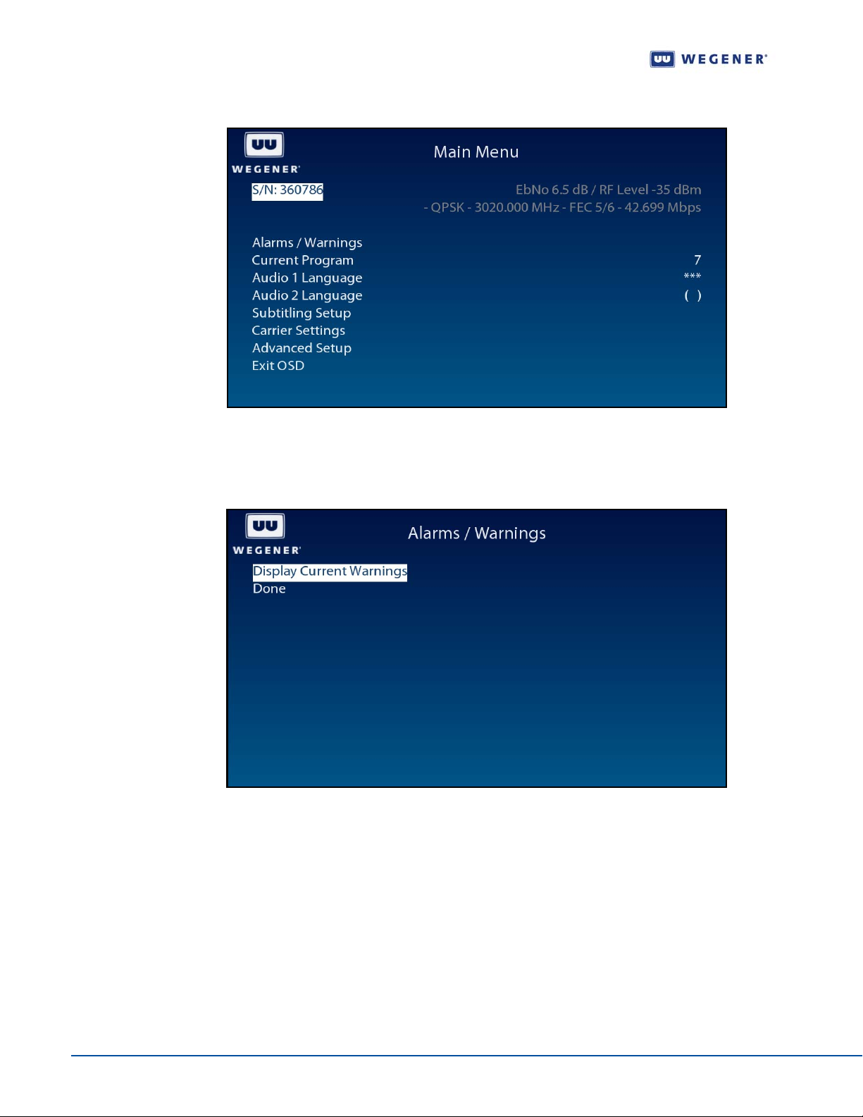
When an Alarm or a Warning condition arises, the Main Menu OSD screen shall have an
entry to display Alarms/Warnings.
1. Press any push-button on the front-panel to display the Main Menu.
current playlist
Section 3.1
www.wegener.com 800092-01 Rev. A 37
Page 48
Operation
Figure 3.32: iPump 562 OSD Main Menu
2. Press the down arrow button to select Alarms/Warnings.
3. Press Enter.
Figure 3.33: iPump 562 OSD Alarms / Warnings
4. Select Display Current Warnings.
5. Press Enter.
38 800092-01 Rev. A www.wegener.com
Page 49

Unity 552 User’s Manual
Figure 3.34: iPump 562 OSD Display Current Warnings
www.wegener.com 800092-01 Rev. A 39
Page 50

Operation
This page intentionally left blank
40 800092-01 Rev. A www.wegener.com
Page 51
CHAPTER 4 SEARCH FUNCTIONS
4.1 Perms/Temps/Searching & Settings
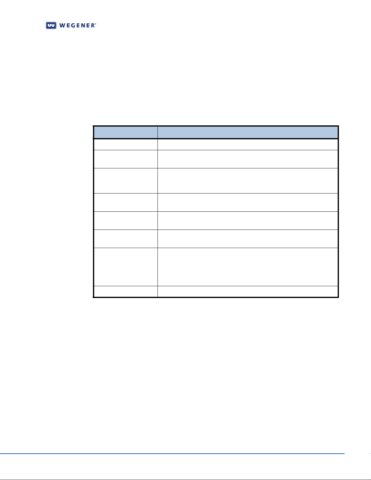
The term "settings" is used throughout this document and includes the following set of
parameters:
Table 4.1: Settings Parameters for the iPump 562
Setting Description
Modulation S28PSK/S2QPSK/QPSK
RF Switch/Pol If IRD is configured for Universal LNB, H or V are valid. Specify RF port 1-
4 for four-port RF configuration.
Carrier The downlink frequency specified in MHz with up to two decimal places.
This value’s absolute difference with the LNB LO frequency is used as
specified in the technical specifications. (e.g. 3720.00 MHz).
Data_rate Data rate is specified in Mbps with up to three decimal places. See the
technical specifications for the applicable range. (e.g. 41.470 Mbps).
Unity 552 User’s Manual
Fec_rate The inner FEC code ratio and can have one of the values specified in the
technical specifications. (e.g. 3/4).
Tag_site V alue of 0-14 (15 is a special NO Tag case) specifying the location of this
carrier’s tag frequency.
[program] The program number from the MPEG Program Association Table. This
must be number from 1 to 65535. If omitted or an ‘*’ is entered, the unit
will select the first available program stream. Note that this number points
to the PID for the Program Map T able for what we might call a “service” (a
single video channel and associated audio signals).
Label A string of characters for identification.
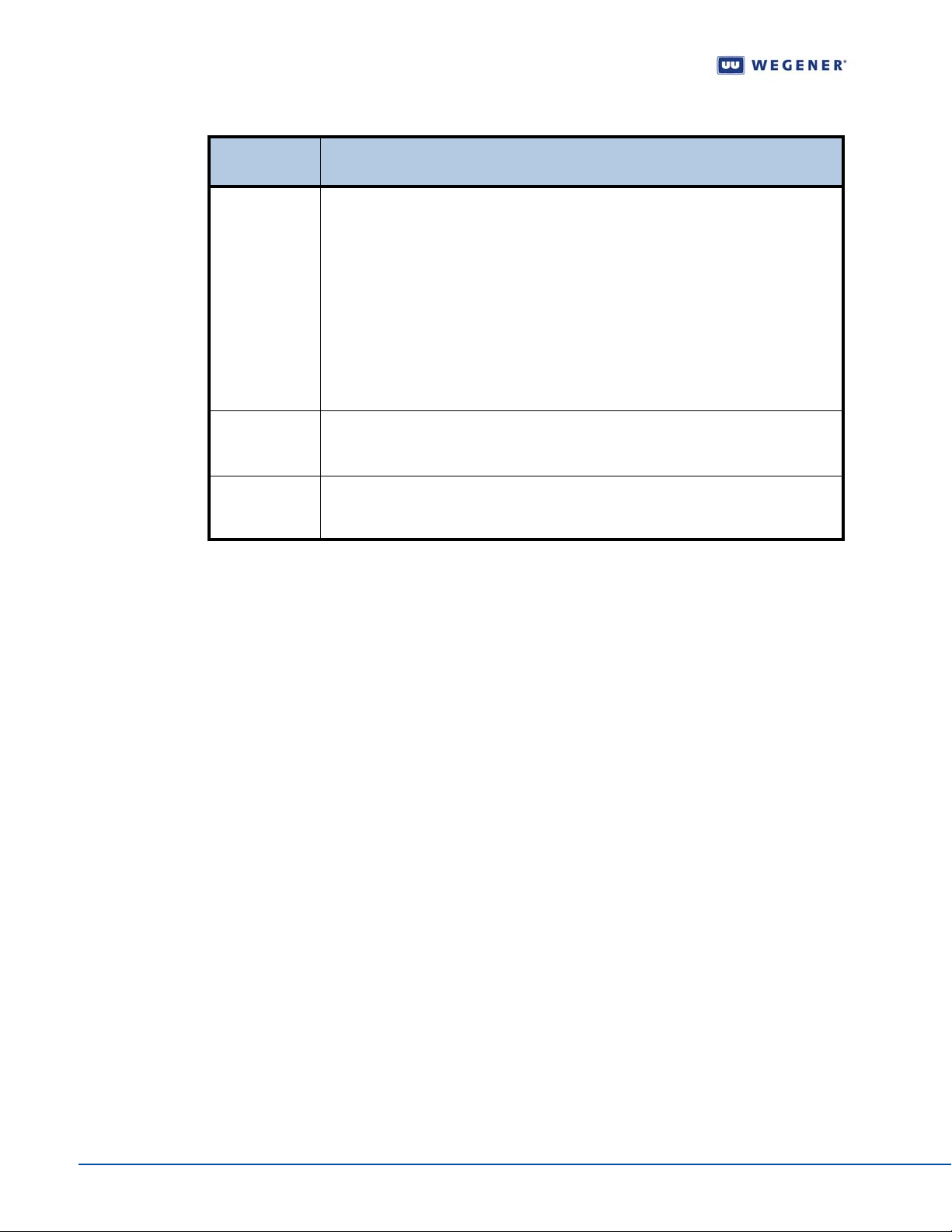
The IRD is acting on one of three groups of settings at any given time, each of which is
described in
Table 4.2
www.wegener.com 800092-01 Rev. A 41
Page 52
Search Functions
Table 4.2: iPump 562 Settings Groups
Settings
Group
Temp
Perm
Search The search settings are active while in Carrier Search or Header Search. When the
These settings are entered via Compel or the TEMP / TEMPCH terminal
commands. The unit is said to be inserting when it is configured to the temp
settings. The maximum length of an insert is approximately 18 hours (65535
seconds). An insert terminates when:
1. it times out,
2. an ABORT command is received,
3. power is cycled, or
4. an invalid header is seen.
Any Temp commands received while the receiver is currently inserting are ignored.
If a Perm command is received while inserting, the perm settings are updated but
not acted on until the insert is terminated.
The perm settings are entered via Compel, the PERM / PERMCH terminal, or
OSD Carrier Select screen, or automatically from within a search mode. (See
below.) The perm settings are the only settings group that are stored in NVRAM.
unit finds what it is looking for in the search mode, it copies the search settings to
the perm settings. These are then considered to be the active settings.
4.2 Settings Table (or Search Table)
Description
This is an internal database ret ained in non-volatile memory (u naffected by loss of powe r). It
contains a list of alternate carrier settings. Each valid entry is a complete description of a
carrier/program setting (as used in a Perm command). This list is entered at customer
request at the factory, and may be edited using
terminal commands. The entries are referred to as "Table Entries" or "Search Settings
Entries", etc.
The Settings Table is typically used for one of two possible operations. The first is for local
users to quickly pre-program carrier/program combinations and tune the IRD to one of
them. The second is as a source of alternate fallback carriers for times when the "normal"
carrier is lost or has a failure in its
4.3 Signal Quality Monitoring
The iPump 562 provides monitoring of different parameters of RF signal quality while
tracking a carrier.
Note: Beyond 15 dB, Eb/No readings are not accurate. For the following inner FEC ratios,
display any Eb/No values above the limits shown as >xx dB: R=1/2, Eb/No >14.0
dB; R=2/3, Eb/No>13.5 dB; R=3/4, Eb/No>13.0 dB; R=5/6, Eb/No>12.5 dB;
R=7/8, Eb/No>12.0 dB. Note that margin may also “top out” as a >yy dB va lue also.
Compel commands or ADDS and DELS
Compel stream.
42 800092-01 Rev. A www.wegener.com
Page 53
Unity 552 User’s Manual
Table 4.3: Signal Quality Information
Parameter Description
Modulation 8PSK/QPSK/S1
RF Switch/Pol If IRD is configured for Universal LNB, H or V are valid. Specify RF port 1-4
for four-port RF configuration.
Carrier The downlink frequency specified in MHz with up to two decimal places.
This value’s absolute difference with the LNB LO frequency is used as
specified in the technical spec ifications.
Data_rate Data rate is specified in Mbps with up to three decimal places. See the
technical specifications for the applicable range.
Fec_rate The inner FEC code ratio and can have one of the values specified in the
technical specifications.
Tag_site Value of 0-14 (15 is a special NO Tag case) specifying the location of this
carrier’s tag frequency
[program] The program number from the MPEG Program Association Table. This must
be number from 1 to 65535. If omitted or an ‘*’ is entered, the unit will select
the first available program stream. Note that this number points to the PID
for the Program Map Table for what we might call a “service” (a single video
channel and associated audio signals).
Label A string of characters for identification.
4.4 Frequency Tagging
General Rules
Frequency Tagging is a mechanism that is used to ensure that an IRD is locked to desired
carrier settings. Sometimes, due to minor offsets in LNB and frequency errors, tuning may
be off by a couple of MHz. To prevent locking to some other near by (adjacent) carrier while
looking for an intended carrier, the acquired carrier contains "frequency tags." These tags
are inserted in
Compel control stream at the uplink to identify the intended carrier frequency.
Traditionally, the tags have been sent at a rate of every 100 or 125 ms.
The iPump 562 supports both single and multiple tags. A carrier settings with "Tag Site"
number, specifies wh ich of the possible ta gs the IRD need to use. The
Tag Site designations from 0 to 15, inclusive. The t ag '15' is reserved for an exception. If the
Carrier Setting shows Tag Site '15' , the Carrier Tags are not required.
The SCPC Frequency Tag Protocol Functional Specification (WCI #16803) gives more
details.
iPump 562 allows for
www.wegener.com 800092-01 Rev. A 43
Page 54

Search Functions
This page intentionally left blank
44 800092-01 Rev. A www.wegener.com
Page 55

5.1 Warranty
The following warranty applies to all Wegener Communications products including the
iPump 562:
Unity 552 User’s Manual
CHAPTER 5 CUSTOMER SERVICE
All Wegener Communications products are warranted against defective materials and
workmanship for a period of one year after shipment to customer.
Communications
Wegener Communications' option, replacing parts, subassemblies, or entire
assemblies.
or consequential damages. This warranty does not cover parts or equipment which
have been subject to misuse, negligence, or accident by the customer during use.
All shipping costs for warranty repairs will be prepaid by the customer. There are no
other warranties, express or implied, except as stated herein.
' obligation under this warranty is limited to repairing or, at
Wegener Communications shall not be liable for any special, indirect,
Wegener
5.2 Technical Support
If the unit should fail to perform as described, if you need help resolving pr oble ms with your
iPump 562, or for questions about obtaining service for your iPump 562, please contact
Wegener Communications Customer Service
mail
To return a product for service:
1. Obtain a Return Material Authorization (RMA) number by completing and faxing a
copy of the
information to:
2. To help us identify and control returned units, plainly write the RMA number on the
outside of the product-shipping container . This will help us return your unit to you as
quickly as possible.
3. Return the product, freight prepaid, to the address below:
Service Department RMA# ________
Wegener Communications, Inc.
359 Curie Drive
Alpharetta, GA 30005
at (770) 814-4057, Fax (678) 624-0294, or e-
RMA Request Form to (678) 624-0294. Or you may e-mail the same
Note: All returned material must be shipped freight prepaid. C.O.D. shipments will not be
accepted.
www.wegener.com 800092-01 Rev. A 45
Page 56

Customer Service
This page intentionally left blank
46 800092-01 Rev. A www.wegener.com
Page 57
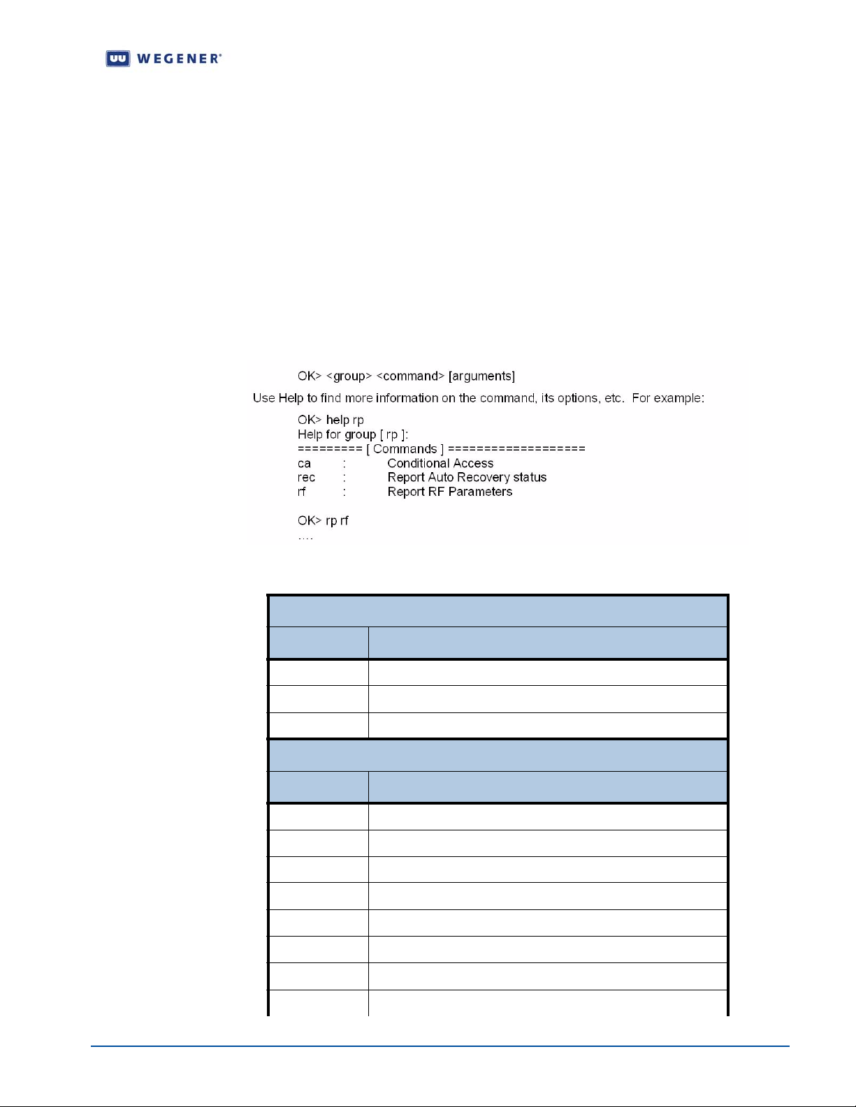
APPENDIX 1 TERMINAL DIAGTERM COMMANDS
The iPump 562 provides command-line interface, Diagterm. The diagterm can be accessed
either using a RS-232 serial port or logging through LAN IP interface using Linux. The
diagterm commands are used to control or monitor the IRD operations. This method may be
used in conjunction other ways to control or monitor, namely,
Apx 1.1 Diagterm Group Commands
Some of the Diagterm terminal commands are grouped under common group name. The
commands belonging to a group perform related functions. Following is a list of groups and
their commands along with synopsis for each. A general syntax for the group command is:
Unity 552 User’s Manual
Compel and OSD.
Table Apx 1.1: Diagterm Group Commands
Group Name: rp
Command Synopsis
ca Report Conditional Access Information
rec Report Recovery Status
rf Report RF Parameters
Group Name: r
Command Synopsis
c Report Carrier Status
st Report Preset Table
s Report Settings Status
p Report Configuration Information
ns Report Network Services Status
http Report HTTP Information
g
Report Compel Group Table
r Report Relays Status
www.wegener.com 800092-01 Rev. A 47
Page 58
groups Report List of Groups
Group Name: rdbs
Command Synopsis
report Report RBDS Status
test Send test message to RBDS port "test <port> <message>
Group Name: lan
Command Synopsis
ip Set Static LAN IP Address of the Unit
gateway Set Network Gateway for LAN Interface
mode Set LAN Addressing Mode (DHCP, STATIC,WEG)
setup Set IP Address and Subnet mask for the LAN port
subnet Set static LAN subnet mask
Group Name: output
Command Synopsis
aspect Set output aspect ratio of the display device 4x3;16x9;14x9
cc Set closed captioning mode [tv|cc1|cc2|cc3|cc4|dtv]
scaling Set output display scaling mode [letterbox|panscan]
Group Name: sigma
Command Synopsis
ver Print version information
Group Name: http
Command Synopsis
proxy Set the proxy server for http
Group Name: snmp
Command Synopsis
community Set SNMPV2 Community Access String
Apx 1.2 Diagterm Individual Commands
The diagterm individual commands are no t group ed together under common group s. These
commands perform functions such as setting audio attenuation or turning on LNB power.
48 800092-01 Rev. A www.wegener.com
Page 59
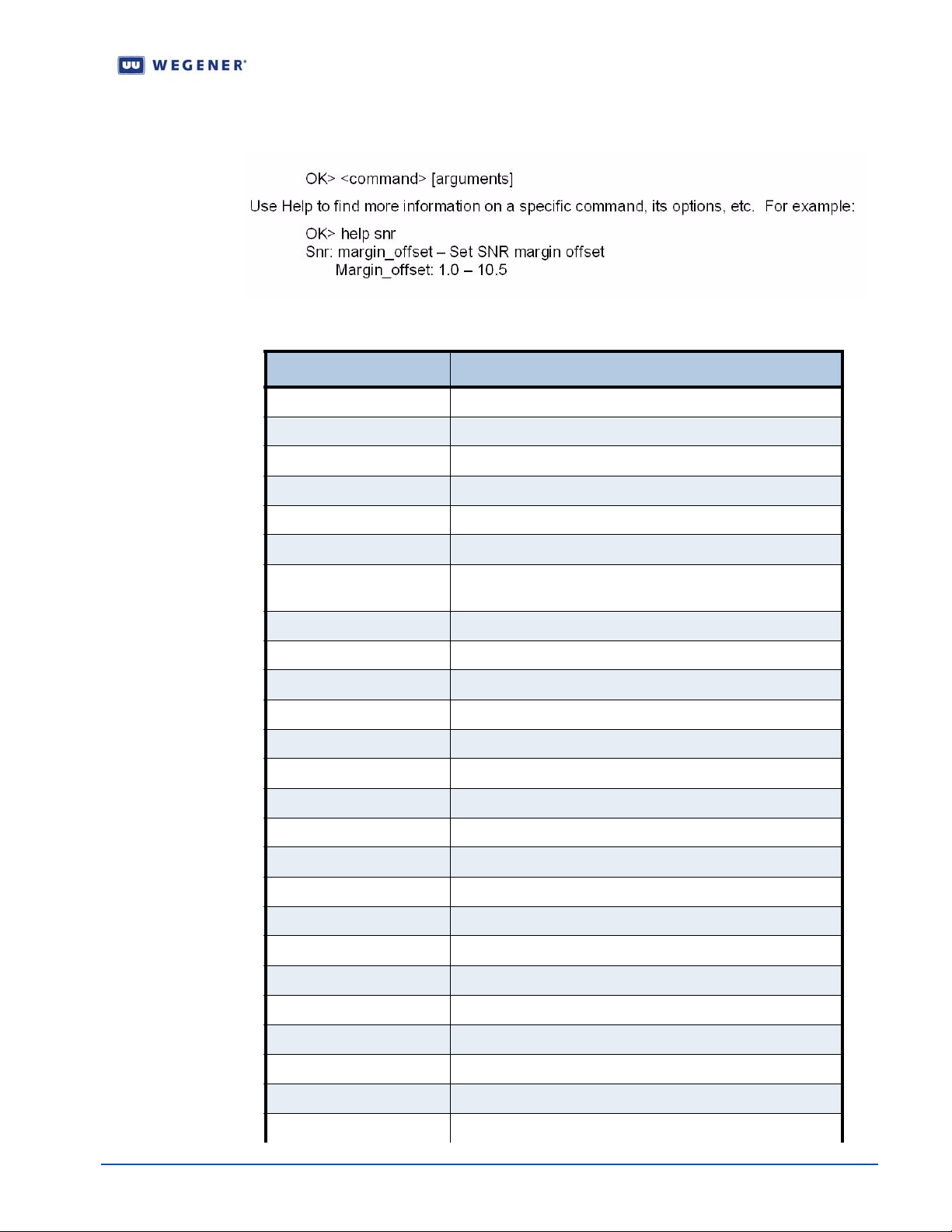
Unity 552 User’s Manual
Following is a list of commands along with synopsis. A general syntax for the group
command is:
Table Apx 1.2: Diagterm Individual Commands
Command Synopsis
abortrec Tune to Last Successful (S) or Last commanded (C)
abort Abort Temporary Insert
adds Add Location Settings
ap Audio Program
ap2 Audio Program 2
audatten Audi o Attenuation
audroute Set Audio Routing (S-Stereo; 1 or 2 Left/Right; R-Reverse
Stereo)
contentaccess Set access level for content on HDD (Read-only or Full)
dels Delete Location Settings
errors Set Alarm Threshold
ifconfig Display current ETHERNET device(s) configuration
lnbpwr Turn LNB Power ON/OFF
lnbselect Set LNB Mode UNIV/ASTRA or STD/LO
margin Set margin offset (Range: 1.0 - 10.5 dB)
movep Move Preset entry (source and destination entry #'s)
permch Set perm settings from search table (Position: 1-48)
perm Set Perm Settings
port Select RBDS port
re Turn solid-state Relays On or Off
savep Save current Settings to a Preset entry
Service Enable or Disable named service
setlnb Set LNB LO Frequency
settimeout Set Timeout (Source #2-5 and time)
set Set Individual Carrier Parameters
snr Set SNR margin offset
www.wegener.com 800092-01 Rev. A 49
Page 60
Command Synopsis
spdif Set SPDIF Mode
sp Select default program for carrier (program #)
tempch Set temp settings from settings table
temp Set temp settings
50 800092-01 Rev. A www.wegener.com
Page 61

APPENDIX 2 MENU TREE
The following page shows the LCD navigation for the iPump 562.
Unity 552 User’s Manual
www.wegener.com 800092-01 Rev. A 51
Page 62
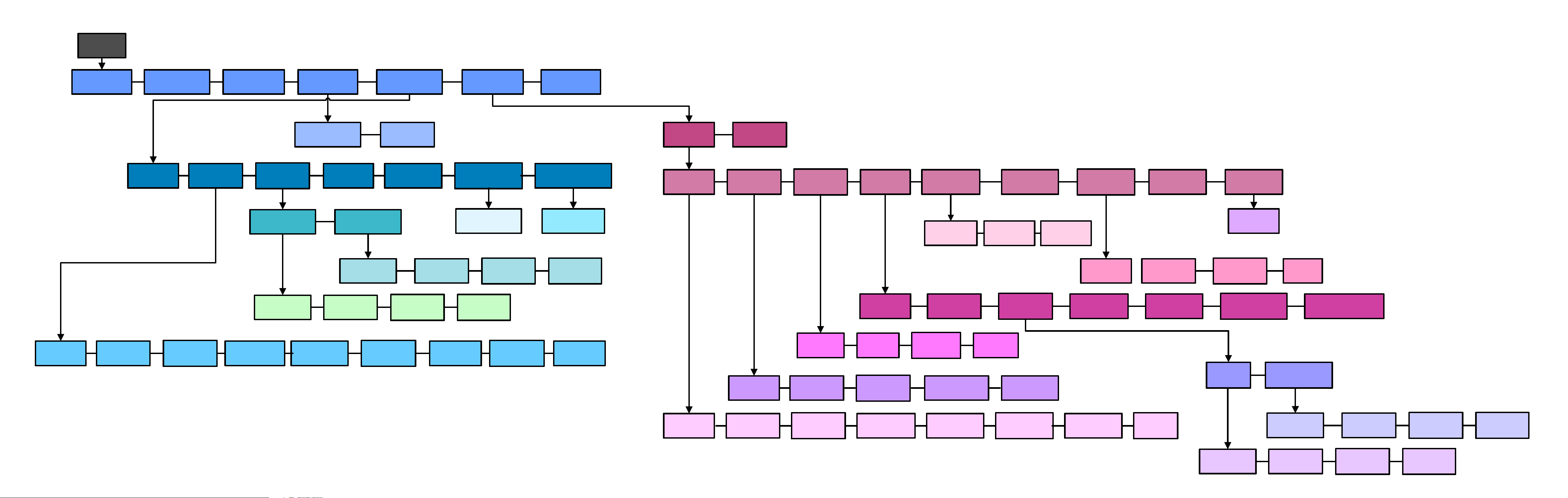
MAIN
MENU
CURRENT
PROGRAM
AUDIO 1 LANG AUDIO 2 LANG
STATUS
CURRENT
CHANNEL
LNB LO
SETUP
LNB LO
SELECT
SUBTITLING
SETUP
CARRIER
SETTINGS
LANGUAGE STYLE
LNB DC
POWER
SNR MARGIN
WARNING
LNB LO
CUSTOM FREQ
PORT 1 LNB
LO FREQ
QUALITY SETUP
THRESHOLDS
PORT 2 LNB
LO FREQ
ADVANCED
SETUP
SIGNAL
INDICATOR
PORT 3 LNB
LO FREQ
EXIT OSD
SIGNAL
STRENGTH METER
CENTER ZOOM
PORT 4 LNB
LO FREQ
UNIT SETUP
DECODER
SETUP
UNIT
STATUS
AUDIO
SETUP
LAN IP
SETTINGS
CARRIER
SETTINGS
SERIAL
PORT
DEVICE
ASSIGNMENT
USER RELAY
SETUP
CONSOLE
BAUDRATE
PRINTER
BAUD
DATE/TIME
SETUP
CURRENT
DATE
UNIT LABEL APP SWITCH
BACKUP
SOFTWARE
CURRENT
TIME
TIMEZONE DST
RF-INPUT
PORT
PORT 1 LNB
LO TYPE
PORT 2 LNB
LO TYPE
PORT 3 LNB
LO TYPE
PORT 4 LNB
LO TYPE
FREQUENCY DATA RATE MODULATION FEC RATIO PROGRAM TAG SITE
SAVE ALL
CHANGES?
SYMBOL
RATE
DECODER
SOURCE
AUDIO
PORT
TV ASPECT
RATIO
LAN
CONFIG
AUDIO
LANGUAGE
OUTPUT
SCALING
STATUS
LAN IP
ADDR
AUDIO
ROUTING
CLOSED
CAPTIONING
CURRENT
CHANNEL
LAN
NETMASK
AUDIO
ATTENUATION
COMPOSITE
OUT
LAN
GATEWAY
S/PDIF MODE
COMPONENT
LNB LO
SETUP
OUT
LNB DC
POWER
COMPONENT
VRefresh
SNR MARGIN
WARNING
HDMI OUT
SIGNAL
QUALITY SETUP
LNB LO
SELECT
PORT 1 LNB
LO TYPE
SIGNAL STRENGTH
LNB LO
CUSTOM FREQ
PORT 1 LNB
LO FREQ
PORT 2 LNB
LO TYPE
METER
PORT 2 LNB
LO FREQ
PORT 3 LNB
LO TYPE
PORT 3 LNB
LO FREQ
PORT 4 LNB
LO TYPE
PORT 4 LNB
LO FREQ
Page 63

Unity 552 User’s Manual
APPENDIX 3 RMA REQUEST FORM
Apx 3.1 Return Materials Authorization Request Form
http://www.wegener.com/custservrma.htm
Figure Apx 3.1: RMA Request Form
E-mail: [email protected] Fax: (678) 624-0294
Company Name:
Bill-To Address:
Ship-To Address:
Contact Name:
Phone # ( ) - Fax #: ( ) Complete Model #:
Serial #:
In Warranty:
Problem:
Additional
Comments:
Yes No
www.wegener.com 800092-01 Rev. A 53
Page 64

This page intentionally left blank
54 800092-01 Rev. A www.wegener.com
Page 65

INDEX
Unity 552 User’s Manual
Numerics
22 KHz tone. . . . . . . . . . . . . . . . . 9
A
address
customer service . . . . . . . . . . 45
manual comments . . . . . . . . . . 1
return materials . . . . . . . . . . . 45
Wegener Communications. . . . ii
Advanced Setup . . . . . . . . . . . . 22
AFD . . . . . . . . . . . . . . . . . . . . 2, 37
airflow . . . . . . . . . . . . . . . . . . . . 11
alarms . . . . . . . . . . . . . . . 5, 14, 15
ambient operating temperat ur e . 11
Application Switch . . . . . . . . . . . 30
arrows . . . . . . . . . . . . . . . . . . . . 14
Assured File Delivery. . . . . . . 2, 37
Audio 1 & 2 . . . . . . . . . . . . . . . . . 4
audio decoder . . . . . . . . . . . . . . . 8
Audio Out. . . . . . . . . . . . . . . . . . . 3
audio output. . . . . . . . . . . . . . 8, 25
audio parameters. . . . . . . . . . . . . 8
audio ports. . . . . . . . . . . . . . . . . . 4
Audio Setup. . . . . . . . . . . . . . . . 25
B
baud rates . . . . . . . . . . . . . . . . . . 9
C
Carrier . . . . . . . . . . . . . . . . . 41, 43
Carrier Settings . . . . . . . . . . . . . 17
chassis. . . . . . . . . . . . . . . . . . . . 10
circuit overload . . . . . . . . . . . . . 12
Clear Signal Counters . . . . . . . . 36
closed captioning. . . . . 7, 8, 24, 48
Compel
CA cipher . . . . . . . . . . . . . . . . . 2
CA Conditional Access. . . . . . . 2
Channel Information. . . . . . . . 18
control functions . . . . . . . . . . . 16
Controlling IRD. . . . . . . . . . . . 13
features . . . . . . . . . . . . . . . . . . 2
field-upgradeable . . . . . . . . . . . 2
frequency tags . . . . . . . . . . . . 43
network. . . . . . . . . . . . . . . . . . . 2
network control. . . . . . . . . . . . . 2
satellite network control . . . . . . 2
Settings Group . . . . . . . . . . . . 42
Settings Table . . . . . . . . . . . . 42
Component Out. . . . . . . . . . . . . 25
component video. . . . . . . . . . . . . 3
component video output . . . . . . . 8
Component V-Refresh. . . . . . . . 25
Composite Out . . . . . . . . . . . . . 25
composite video . . . . . . . . . . . . . 3
composite video output . . . . . . . . 7
connections. . . . . . . . . . . . . . . . . 3
connectors. . . . . . . . . . . . . . . . . . 3
copyright . . . . . . . . . . . . . . . . . . . ii
current. . . . . . . . . . . . . . . . . . . . . 9
Current Channel . . . . . . . . . . . . 17
Current Quality . . . . . . . . . . . . . 32
customer service. . . . . . . . . . . . 53
phone number . . . . . . . . . . . . 45
C-Video . . . . . . . . . . . . . . . . . . 3, 4
D
Data_rate. . . . . . . . . . . . . . . 41, 43
Date/Time Setup . . . . . . . . . . . . 29
DB-9 female . . . . . . . . . . . . . . . . 5
DC IN. . . . . . . . . . . . . . . . . . . . . . 5
decoder . . . . . . . . . . . . . . . . . . . . 6
video. . . . . . . . . . . . . . . . . . . . . 6
Decoder Setup . . . . . . . . . . 24, 26
desktop installation . . . . . . . . . . 12
DHCP . . . . . . . . . . . . . . . . . 27, 48
diagterm commands . . . . . . . . . 47
DVB-S2 . . . . . . . . . . . . . 1, 2, 5, 17
E
Eb/No readings . . . . . . . . . . . . . 42
Elapsed Times. . . . . . . . . . . . . . 34
e-mail
customer service . . . . . . . . . . 45
return materials . . . . . . . . . . . 45
ethernet. . . . . . . . . . . . . . . . . . . . 4
external input/output . . . . . . . . . . 3
F
fax number
customer service . . . . . . . . . . 45
manuals . . . . . . . . . . . . . . . . . . 1
return materials . . . . . . . . . . . 45
Wegener Communications. . . . ii
features . . . . . . . . . . . . . . . . . . . . 2
Fec_rate . . . . . . . . . . . . . . . 41, 43
frequency. . . . . . . . . . . . . . . . . . . 9
frequency tagging . . . . . . . . . . . 43
front panel
buttons . . . . . . . . . . . . . . . . . . 14
controls . . . . . . . . . . . . . . . . . 13
G
general information . . . . . . . . . . . 1
GPIO. . . . . . . . . . . . . . . . . . . . . . 5
grounded. . . . . . . . . . . . . . . . . . 12
H
HDMI. . . . . . . . . . . . . . . . . . 2, 3, 4
HDMI Out . . . . . . . . . . . . . . . . . 25
History This Setting. . . . . . . . . . 33
I
impedance. . . . . . . . . . . . . . . . . . 8
Indicator Threshold . . . . . . . . . . 20
indicators. . . . . . . . . . . . . . . . . . 13
Input/Output . . . . . . . . . . . . . . . . 4
inspection . . . . . . . . . . . . . . . . . 11
interfaces. . . . . . . . . . . . . . . . . . . 3
IRD . . . . . . . . . . . . . . . . . . . . . . 41
L
label. . . . . . . . . . . . . . . . . . . 41, 43
LAN. . . . . . . . . . . . . . . . . . . . . . 27
LAN Decode options . . . . . . . . . 26
LAN IP Info . . . . . . . . . . . . . . . . 35
LAN IP Setup . . . . . . . . . . . . . . 26
LCD
navigation. . . . . . . . . . . . . . . . 51
LNB
DC Power. . . . . . . . . . . . . . . . . 9
LNB Setup. . . . . . . . . . . . . . . . . 18
location . . . . . . . . . . . . . . . . . . . 11
M
manual overview. . . . . . . . . . . . . 1
menu tree . . . . . . . . . . . . . . . . . 51
modulation. . . . . . . . . . . . . . 41, 43
mounting . . . . . . . . . . . . . . . . . . 11
N
Network History. . . . . . . . . . . . . 34
networking options . . . . . . . . . . 26
NTSC . . . . . . . . . . . 1, 2, 3, 6, 7, 8
O
operation. . . . . . . . . . . . . . . . . . 13
options. . . . . . . . . . . . . . . . . . . . . 2
OSD screens
Advanced Setup. . . . . . . . . . . 22
Application Switch . . . . . . . . . 30
www.wegener.com 800092-01 Rev. A 55
Page 66

Audio Setup . . . . . . . . . . . . . . 25
Carrier Settings. . . . . . . . . . . . 17
Clear Signal Counters. . . . . . . 36
Current Channel . . . . . . . . . . . 17
Current Quality . . . . . . . . . . . . 32
Date/Time Setup. . . . . . . . . . . 29
Decoder Setup . . . . . . . . . 24, 26
Elapsed Times . . . . . . . . . . . . 34
History This Setting. . . . . . . . . 33
Indicator Threshold. . . . . . . . . 20
LAN IP Info . . . . . . . . . . . . . . . 35
LAN IP Setup . . . . . . . . . . . . . 26
LNB Setup. . . . . . . . . . . . . . . . 18
Network History. . . . . . . . . . . . 34
Play out play lists of media files .
37
Signal Quality . . . . . . . . . . . . . 32
Signal Quality Setup . . . . . . . . 19
Signal Strength Meter. . . . . . . 21
Subtitling Setup. . . . . . . . . . . . 21
Terminal Setup . . . . . . . . . . . . 27
Unit Label Setup . . . . . . . . . . . 30
Unit Setup. . . . . . . . . . . . . . . . 23
Unit Status . . . . . . . . . . . . . . . 31
User Relay Setup . . . . . . . . . . 29
Version Info. . . . . . . . . . . . . . . 35
P
PAL . . . . . . . . . . . . . 1, 2, 3, 6, 7, 8
Perm . . . . . . . . . . . . . . . . . . . . . 42
phone jack . . . . . . . . . . . . . . . . . . 4
phone number
customer service. . . . . . . . . . . 45
Wegener Communications . . . . ii
Play out play lists of media files. 37
port. . . . . . . . . . . . . . . . . . . . . . . . 4
power consumption . . . . . . . . 9, 12
precautions . . . . . . . . . . . . . 10, 11
product overview . . . . . . . . . . . . . 1
product specifications . . . . . . . . . 2
program . . . . . . . . . . . . . . . . 41, 43
Q
QPSK. . . . . . . . . . . . . . . . . . . . . . 2
R
rack mounting . . . . . . . . . . . 11, 12
RCA Phono Jack . . . . . . . . . . . . . 3
RCS Phone Jack . . . . . . . . . . . . . 3
rear panel connections . . . . . . . . 3
reliable earthing . . . . . . . . . . . . . 12
Return Material Authorization . . 45
Return Materials Authorization . 53
RF . . . . . . . . . . . . . . . . . . . . . 3, 42
Switch/Pol. . . . . . . . . . . . . . . . 41
RF characteristics . . . . . . . . . . . . 5
RF input . . . . . . . . . . . . . . . . . . . . 5
RF Switch/Pol . . . . . . . . . . . . . . 43
RMA. . . . . . . . . . . . . . . . . . . . . . 45
RMA request form . . . . . . . . . . . 53
RS-232. . . . . . . . . . . . . . . . . . . 4, 9
RS-232 Port. . . . . . . . . . . . . . . . . 3
S
S/PDIF . . . . . . . . . . . . . . . . . . . 3, 4
search
functions . . . . . . . . . . . . . . . . . 41
settings . . . . . . . . . . . . . . . . . . 42
table . . . . . . . . . . . . . . . . . . . . 42
selectable services . . . . . . . . . . . 9
serial port. . . . . . . . . . . . . . . . . 4, 9
settings
groups. . . . . . . . . . . . . . . . . . . 42
parameters . . . . . . . . . . . . . . . 41
table . . . . . . . . . . . . . . . . . . . . 42
Signal Quality . . . . . . . . . . . . . . 32
information . . . . . . . . . . . . . . . 43
monitoring. . . . . . . . . . . . . . . . 42
Signal Quality Setup . . . . . . . . . 19
Signal Strength Meter . . . . . . . . 21
SNMP . . . . . . . . . . . . . . . . . . 2, 48
Static . . . . . . . . . . . . . . . . . . . . . 27
subtitling . . . . . . . . . . . . . 2, 16, 24
Subtitling Setup . . . . . . . . . . . . . 21
T
Tag_site. . . . . . . . . . . . . . . . 41, 43
Tele-text. . . . . . . . . . . . . . . . 2, 7, 8
Temp . . . . . . . . . . . . . . . . . . . . . 42
terminal diagterm commands . . 47
Terminal Setup . . . . . . . . . . . . . 27
U
Unit Label Setup . . . . . . . . . . . . 30
Unit Setup . . . . . . . . . . . . . . . . . 23
Unit Status. . . . . . . . . . . . . . . . . 31
unpacking . . . . . . . . . . . . . . . . . 11
USB . . . . . . . . . . . . . . . . . . . . . . . 4
User Relay Setup . . . . . . . . . . . 29
V
Version Information . . . . . . . . . . 35
video decoder . . . . . . . . . . . . . . . 6
video formats. . . . . . . . . . . . 2, 3, 6
voltage
AC. . . . . . . . . . . . . . . . . . . . . . . 9
DC . . . . . . . . . . . . . . . . . . . . . . 9
W
warranty. . . . . . . . . . . . . . . . . . . 45
weight . . . . . . . . . . . . . . . . . . . . 10
56 800092-01 Rev. A www.wegener.com
Page 67

Page 68

© 2008 Wegener Communications, Inc. All rights reserved.
800092-01 Rev. A
First Edition: July 2008
Wegener Communications, Inc.
Technology Park/Johns Creek
11350 Technology Circle
Duluth, GA 30097-1502
Phone: 770-814-4000
Fax: 770-623-0698
 Loading...