

Page 1
Motors | Automation | Energy | Transmission & Distribution | Coatings
Frequency Inverter
CFW700
User's Manual
Page 2

User's Manual
Series: CFW700
Language: English
Document: 10000771684 / 05
Models: Frame Sizes A...E
Date: 01/2018
Page 3
Page 4

Contents
1 SAFETY INSTRUCTIONS .................................................................1
1.1 SAFETY WARNINGS IN THE MANUAL ................................................. 1
1.2 SAFETY WARNINGS IN THE PRODUCT...............................................1
1.3 PRELIMINARY RECOMMENDATIONS .................................................2
2 GENERAL INSTRUCTIONS ..............................................................3
2.1 ABOUT THE MANUAL ...........................................................................3
2.2 ABOUT THE CFW700 ............................................................................. 3
2.3 IDENTIFICATION ....................................................................................6
2.4 LIST OF AVAILABLE MODELS .............................................................8
2.5 IDENTIFICATION LABELS .....................................................................8
2.6 RECEIVING AND STORAGE .................................................................. 9
3 INSTALLATION AND CONNECTION ................................................10
3.1 MECHANICAL INSTALLATION ..............................................................10
3.1.1 Installation Environment ..............................................................10
3.1.2 Mounting Considerations .............................................................10
3.2 ELECTRICAL INSTALLATION ................................................................11
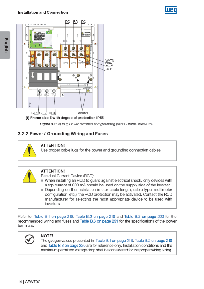
3.2.1 Identification of the Power and Grounding Terminals ............... 12
3.2.2 Power / Grounding Wiring and Fuses ......................................... 14
3.2.3 Power Connections ...................................................................... 15
3.2.3.1 Input Connections ............................................................ 16
3.2.3.2 Power Supply Capacity ...................................................16
3.2.3.3 Dynamic Braking (standard built-in for frame sizes
A, B, C and D and optional built-in for frame size E -
CFW700...DB...) ............................................................................. 16
3.2.3.4 Output Connections .........................................................18
3.2.4 Grounding Connections ............................................................... 19
3.2.5 Control Connections ....................................................................20
3.2.6 Cable Distances ............................................................................ 24
3.3 INSTALLATION ACCORDING TO THE EUROPEAN DIRECTIVE OF
ELECTROMAGNETIC COMPATIBILITY ......................................................24
3.3.1 Conformal Installation .................................................................. 24
3.3.2 Emission and Immunity Levels .................................................... 25
English
4 KEYPAD (HMI) AND BASIC PROGRAMMING ...............................26
4.1 INTEGRAL KEYPAD - HMI-CFW700 ..................................................... 26
4.2 APPLICATIONS .......................................................................................29
4.2.1 PID Regulator Application ............................................................29
4.2.1.1 Academic PID ................................................................... 33
4.2.2 Electronic Potentiometer Application (E.P.) ...............................39
4.2.3 Multispeed Application ................................................................41
4.2.4 3-Wire Start/Stop Command Application ................................... 44
4.2.5 Forward/Reverse Run Application .............................................. 46
Page 5

Contents
5 FIRST TIME POWER-UP AND START-UP .......................................49
5.1 PREPARE FOR START-UP ..................................................................... 49
English
5.2 START-UP ................................................................................................ 49
5.2.1 Oriented Start-up Menu ...............................................................50
5.2.2 Basic Application Menu ..............................................................53
6 TROUBLESHOOTING AND MAINTENANCE ..................................54
6.1 FAULTS AND ALARMS ........................................................................... 54
6.2 SOLUTIONS FOR THE MOST FREQUENT PROBLEMS ......................54
6.3 INFORMATION FOR CONTACTING TECHNICAL SUPPORT .............. 55
6.4 PREVENTIVE MAINTENANCE ............................................................... 56
6.5 CLEANING INSTRUCTIONS ................................................................. 57
7 OPTION KITS AND ACCESSORIES .................................................59
7.1 OPTION KITS .......................................................................................... 59
7.1.1 Built-in RFI Filter (only for frame sizes A, B, C and D) -
CFW700...C3... ........................................................................................ 59
7.1.2 Dynamic Braking IGBT (only for frame size E in 220 / 230 V
and 380…480 V models and for frame sizes D and E in 500…600 V
models) - CFW700...DB... .....................................................................59
7.1.3 Nema1 Protection Degree (only for frame sizes A, B, C and E) -
CFW700...N1... ........................................................................................ 59
7.1.4 IP55 Protection Degree (only for frame sizes B and C) -
CFW700...55... .........................................................................................59
7.1.5 IP21 Protection Degree (only for frame sizes A, B and C) -
CFW700...21... .........................................................................................59
7.1.6 STO Function - CFW700...Y1........................................................59
7.1.7 24 Vdc External Control Power Supply - CFW700...W1... ..........60
7.2 ACCESSORIES ....................................................................................... 60
8 TECHNICAL SPECIFICATIONS ........................................................62
8.1 POWER DATA ......................................................................................... 62
8.2 ELECTRICAL/GENERAL SPECIFICATIONS ......................................... 63
8.3 CODES AND STANDARDS ....................................................................65
8.4 CERTIFICATIONS ................................................................................... 65
Page 6

Page 7
Page 8

Page 9

General Instructions
“Optimal Braking” function for the vector control, allowing the controlled braking of the motor
and avoiding external braking resistor for some applications.
English
“Self-Tuning” feature for vector control. It allows the automatic adjustment of the regulators
and control parameters from the identification (also automatic) of the motor parameters and
load.
The main components of the CFW700 can be viewed in Figure A.1 on page 207.
4 | CFW700
Page 10

Page 11

General Instructions
2.3 IDENTIFICATION
English
Special
Software
Special
Hardware
Control
External
Stop
Safety
Table 2.1: Identification of the CFW700 inverters
Version
Blank =
standard.
Sx =
special
software.
Version
Voltage
(3)
Hxx or K xx = special
hardware.
W1 = 24 Vdc power supply,
independent of the control
voltage.
Blank = not available.
according to EN 954-1/ISO 13849-1,
category 3.
(5)
Switch
Discon.
(1)
Level
Emission
Conducted
(1)
Blank = not available
DS = with discon. switch
(4)
Enclosure
(1)
Braking
Rated
Voltage
Phases
Number
of Power
Rated
Output
Current
Model Identification
Size
Frame
Refer to Table 2.2 on page 7.
NB = without dynamic braking (valid only for frame size
(2)
E inverters).
DB = with dynamic braking. Blank = standard.
20 = IP20.
21 = IP21 (not available for frame size E inverters). Blank = not available.
N1 = Nema1 enclosure (UL Type 1) (protection degree according to
IEC: IP21 for frame sizes A, B and C and IP20 for frame sizes D and E).
55 = IP55 (only for 200...240 V and 380...480 V models of frame sizes
B, C, D and E).
Blank = it is not in accordance with the standard conducted emission levels. Y1 = with STO function (Safe Torque Off)
C3 = according to category 3 (C3) of IEC 61800-3, with built-in C3 RFI filter.
and
Series
Product
6 | CFW700
CFW700
Eg.: CFW700 A 03P6 T 4 DB 20 C3 DS Y1 W1 --- --
Available options
Notes:
(1) The options available for each model are shown in Table 2.2 on page 7.
(2) This option is not available for frame size D inverters (the standard product is Nema1).
(3) This option is not available for frame size A inverters with the N1 option (Nema1 enclosure) or IP21.
(4) It is possible to meet the requirements of category C2 with this filter on mechanics A models. For further details, see Table B.7 on page 234.
(5) Only applicable to models with degree of protection IP55.
Page 12

General Instructions
Table 2.2: Options available for each model according to the size, power supply, rated current and voltage
of the inverter
Frame
Size
A (IP20)
B (IP55)
A (IP20)
B (IP55)
A (IP20)
B (IP55)
B
C
D
E
A (IP20)
B (IP55)
B
C
D
E
B
C
D
E
Available Options for the Remaining Identification
Rated Output
Curre nt for ND
Overload
06P0 = 6.0 A
07P0 = 7.0 A
06P0 = 6.0 A
07P0 = 7.0 A
10P0 = 10 A Blank or C3
07P0 = 7.0 A
10P0 = 10 A
13P0 = 13 A
16P0 = 16 A
24P0 = 24 A
28P0 = 28 A
33P5 = 33.5 A
45P0 = 45 A
54P0 = 54 A
70P0 = 70 A
86P0 = 86 A
0105 = 105 A
0142 = 142 A
02 11 = 211 A
03P6 = 3.6 A
05P0 = 5.0 A
07P0 = 7.0 A
10P0 = 10 A
13P5 = 13.5 A
17P0 = 17 A
24P0 = 24 A
31P0 = 31 A
38P0 = 38 A
45P0 = 45 A
58P5 = 58.5 A
70P5 = 70.5 A
88P0 = 88 A
0105 = 105 A
0142 = 142 A
0180 = 180 A
02 11 = 211 A
02P9 = 2.9 A
04P2 = 4.2 A
07P0 = 7.0 A
10P0 = 10 A
12P0 = 12 A
17P0 = 17 A
22P0 = 22 A
27P0 = 27 A
32P0 = 32 A
44P0 = 44 A
22P0 = 22 A
27P0 = 27 A
32P0 = 32 A
44P0 = 44 A
53P0 = 53 A
63P0 = 63 A
80P0 = 80 A
0107 = 107 A
0125 = 125 A
0150 = 150 A
Number of
Power Phases
B = single-phase or
three-phase
S = Single-phase 2 = 200…240 V DB
T = three-phase
T = three-phase 4 = 380 / 480 V
T = three-phase 5 = 50 0...600 V
Rated Voltage
2 = 200…240 V DB
2 = 200…240 V DB
2 = 220…230 V NB or DB 20, N1 or 55 C30180 = 180 A
NB or DB 20, N1 or 55 C3
NB or DB
Braking
DB
DB 20, 21 or N1
Codes o f the Inverte rs
(standard product is shown in bold)
Enclosure
(Protection
Degree)
20, 21, N1
or 55
20, 21, N1
or 55
20, 21, N1
or 55
20, 21, N1
or 55
21, N1 or 55
20, 21, N1
or 55
20, 21, N1
or 55
21, N1 or 55
21 or N1
20 or N1 C3
Discon.
Switch
Blank
Blank or D S
Blank or D S
Blank
Blank or DS
Blank or DS
Blank
Emission Level
Condu cted
Blank
C3
Blank or C3
Blank or C3
Blank or C3
English
CFW700 | 7
Page 13

Page 14

Page 15

Installation and Connection
3 INSTALLATION AND CONNECTION
3.1 MECHANICAL INSTALLATION
English
3.1.1 Installation Environment
Avoid installing the inverter in an area with:
Direct exposure to sunlight, rain, high humidity, or sea-air.
Inflammable or corrosive gases or liquids.
Excessive vibration.
Dust, metallic particles, and oil mist.
Environment conditions for the operation of the inverter:
Inverter surrounding temperature: from -10 ºC up to Ta according to the Table B.5 on page 223.
A current derating of 2 % is necessary for each degree Celsius above Ta up to a limit of:
- 60 °C for models of frames A, B, C and D with IP2X or Nema1 degree of protection.
- 55 °C for models of frame E with IP2X or Nema1 degree of protection.
- 50 °C for all models with IP55 degree of protection.
Humidity: from 5 % to 95 % non-condensing.
Altitude: up to 1000 m (3,300 ft) - standard conditions (no derating required).
From 1000 m to 4000 m (3,300 ft to 13,200 ft) - current derating of 1 % each 100 m (or 0.3 %
each 100 ft) above 1000 m (3,300 ft) altitude.
From 2000 m to 4000 m (6,600 ft to 13,200 ft) above sea level - maximum voltage reduction
(240 V for 200...240 V models, 230 V for 220...230 V models, 480 V for 380...480 V models
and 600 V for 500...600 V models) of 1.1 % for each 100 m (330 ft) above 2000 m (6,600 ft).
Pollution degree: 2 (according to EN50178 and UL508C) with non-conductive pollution.
Condensation shall not originate conduction through the accumulated residues.
3.1. 2 Mounting Considerations
External dimensions, fixing holes position and net weight of the inverter are presented at Figure
B.2 on page 240 and Figure B.3 on page 242. Please refer to Figure B.4 on page 243 to
Figure B.11 on page 250 for more details of each inverter size.
Install the inverter upright on a flat surface. First place the screws on the surface where the
drive is going to be installed, install the drive and then tighten the screws.
Frame size E inverters with N1 option (CFW700E...N1...):
After fixing the inverter, install the upper Nema 1 kit on the inverter using the two M8 screws
provided with the product.
10 | CFW700
Page 16

Page 17

Page 18

Page 19
Page 20

Page 21

Page 22

Page 23

Page 24

Page 25

Installation and Connection
3.2.5 Control Connections
The control connections (analog inputs/outputs and digital inputs/outputs), shall be performed
English
in connector XC1 of the CC700 Control Board. Functions and typical connections are presented
in Figura 3.5 on page 21.
(1)
Linedrive encoder or push-pull
A
A
+V
Blue
White
A
+5 V-ENC
B
Red
Green
B
A
DO5
>300 Ω
RL1-N A
Active high digital inputs
+24 V
GND (24 V)
Z
Z
B
Pink
Yel lo w
Z
B
AI2+
GND
GreyZ
Brown
DO2
DO3
DO4
>300 Ω
>300 Ω
RL1-NF
>300 Ω
RL1-C
A (-) - RS-485
B (+) - RS-485
GND-ENC
AI2-
(2)
DI5
DI6
DI7
DI8
≥5 kΩ
AI1-
AI1+
REF+
(1) Refer to Figura 3.5 on page 21 (b) for the open-collector encoder connection.
(2) Refer to Figura 3.5 on page 21 (c) for active low digital inputs connection.
REF-
rpm
AO1
amp
AO2
AGND (24 V)
AGND (24 V)
(a) Linedrive encoder or push-pull and active high digital inputs
20 | CFW700
+24 V
COM
GND (24 V)
DI1
DI2
DI3
DI4
Page 26

Page 27

Page 28

Page 29

Installation and Connection
3.2.6 Cable Distances
The power cables and control cables must be separated (relay output cables and other control
English
cables) according to Table 3.3 on page 24.
Table 3.3: Cable distances
Rated Output
Inverter Current
≤ 24 A
≥ 28 A
Cable Length(s)
≤ 100 m (330 ft)
> 100 m (330 ft)
≤ 30 m (100 ft)
> 30 m (100 ft)
Minimum Separation
Distance
≥ 10 cm (3.94 in)
≥ 25 cm (9.84 in)
≥ 10 cm (3.94 in)
≥ 25 cm (9.84 in)
3.3 INSTALLATION ACCORDING TO THE EUROPEAN DIRECTIVE OF
ELECTROMAGNETIC COMPATIBILITY
The inverters with C3 option (CFW700...C3...) have internal C3 RFI filter to reduce electromagnetic
interference. These inverters, when properly installed, meet the requirements of the directive of
electromagnetic compatibility (2014/30/EU).
The CFW700 inverter series has been designed only for industrial applications. Therefore, the
emission limits of harmonic currents defined by the standards EN 61000-3-2 and EN 61000-3-2/A
14 are not applicable.
3.3.1 Conformal Installation
1. Inverters with built-in C3 RFI filter CFW700...C3...
2. Frame sizes A to D inverters with built-in C3 RFI filter capacitors grounding screws and frame
size E with J1 cable in the position (XE1). For more information see Figure A.8 on page
214.
3. Shielded output cables (motor cables) and connect the shield at both ends (motor and
inverter) with a low impedance connection for high frequency. Use PCSx-01 kit supplied
with frame sizes A, B and C inverters. For frame sizes B and C with degree of protection
IP55, use the PCSC-03 shield kit. For frame sizes D and E inverters use the clamps supplied
with the product. Ensure good contact between the cable shield and the clamps. Refer to
Figure 3.4 on page 19 and keep the proper separation from other cables according to
Item 3.2.6 Cable Distances on page 24. The maximum motor cable length and conduction
and radiated emission levels are presented at Table B.7 on page 234. Use an external RFI
filter at the input of the inverter if necessary to have a lower emission level and/or a longer
motor cable length. For more information (RFI filter commercial reference, motor cable length
and emission levels) refer to Table B.7 on page 234.
4. Shielded control cables and separate the remaining cables according to Item 3.2.6 Cable
Distances on page 24.
5. Inverter grounding according to the instructions on Item 3.2.4 Grounding Connections on
page 19.
6. Grounded power supply.
24 | CFW700
Page 30

3.3.2 Emission and Immunity Levels
Table 3.4: Emission and immunity levels
EMC Phenomenon
Emission:
Mains Terminal Disturbance Voltage
Frequency Range: 150 kHz to 30 MHz)
Electromagnetic Radiation Disturbance
Frequency Rang e: 30 MHz to 1000 MHz)
Immunity:
Electrostatic Discharge (ESD) IEC 61000-4-2
Fast Transient-Burst IEC 61000-4-4
Conducted Radio-Frequency Common
Mode
Surge Immunity IEC 61000-4-5
Radio-Frequency Electromagnetic Field IEC 61000-4-3
Basic
Standard
IEC/EN61800-3
IEC 61000-4-6
Installation and Connection
Level
It depends on the inverter model a nd the motor
cable length.
See Table B.7 on page 234.
4 kV for contact discharge and 8 kV for air
discharge.
2 kV / 5 kHz (coupling capacitor) power input
cables;
1 kV / 5 kHz control cables, and remote
keypad cables;
2 kV / 5 kHz (coupling capacitor) motor output
cables.
0.15 to 80 MHz; 10 V; 80 % AM (1 kHz).
Power supp ly cable, motor, control an d remote
keypad (HMI).
1.2/50 μs, 8/20 μs;
1 kV line-to-line coupling;
2 kV line-to-ground coupling.
80 to 1000 MHz;
10 V/m;
80 % AM (1 kHz).
English
Refer to Table B.7 on page 234 for conducted and radiated emission levels accomplished
with and without external RFI filter. The reference model for the external filter is also presented.
CFW700 | 25
Page 31

Page 32

Page 33

Page 34

Page 35

Keypad (HMI) and Basic Programming
Application examples:
Flow control or pressure in a pipe system.
English
Temperature of a furnace or oven.
Dosing of chemicals in tanks.
The following example defines the terms used by the PID controller.
A pump used in a water pumping system where is necessary to control the pressure of the
pipe. A pressure transducer is installed in the pipe and supplies an analog feedback signal
to the CFW700, which is proportional to the water pressure. This signal is called the process
variable, and can be visualized at the parameter P1012. A setpoint is programmed in the
CFW700 via keypad (P1025), through an analog input (such as a 0-10 V or 4-20 mA signal) or
via communication network. The setpoint is the desired water pressure value that the pump is
supposed to produce, regardless of the consumption variations at the pump output at any time.
It is necessary to set the parameter P0221 or P0222 to 7 = SoftPLC for the operation of the
PID Regulator application.
Definitions:
The Function 1 of the Application at parameters P0231 or P0236 represents the value of
the PID Setpoint.
The Function 2 of the Application at parameters P0231 or P0236 represents the value of
the PID Feedback.
The Function 1 of the Application at parameters P0251 or P0254 represents the value of
the PID Setpoint.
The Function 2 of the Application at parameters P0251 or P0254 represents the value of
the PID Feedback.
The Function 1 of the Application at parameters P0263 or P0270 represents the value of the
Manual/Auto command.
The Function 1 of the Application at parameters P0275 to P0279 represents the VP>VPx
logical condition.
The Function 2 of the Application at parameters P0275 to P0279 represents the VP<VPy
logical condition.
The PID setpoint can receive an analog input signal (AI1 or AI2). It is necessary to set P1016
to 1 = AIx and select which analog input will be used. The analog inputs are set at P0231 (AI1)
or P0236 (AI2) and it is necessary to program it to 5 = Function 1 of the Application in order to
enable the analog inputs for the operation. The following alarm message will be displayed in
case it is not properly done: “A770: Set AI1 or AI2 for Function 1 of the Application”.
The PID setpoint value can be presented via analog output AO1 or AO2. It is necessary to set
P0251 (AO1) or P0254 (AO2) to 17 = Function 1 of the Application. The full scale value of the
variable is 100.0 % and corresponds to 10 V or 20 mA.
30 | CFW700
Page 36

Keypad (HMI) and Basic Programming
The PID feedback can receive an analog input signal (AI1 or AI2). It is necessary to set P0231
(AI1) or P0236 (AI2) to 6 = Function 2 of the Application in order to enable the analog inputs for
the operation. The following alarm message will be displayed in case it is not properly done:
“A772: Set AI1 or AI2 for Function 2 of the Application”.
In case the analog inputs (AI1 and AI2) are programmed with the same function, PID Setpoint
or Feedback, the following alarm message will be displayed and the application will not be
enabled: “A774: AI1 and AI2 were set for the same function”.
The value of the PID feedback can be presented via analog output AO1 or AO2. It is necessary
to set P0251 (AO1) or P0254 (AO2) to 18 = Function 2 of the Application. The full scale value of
the variable is 100.0 % and corresponds to 10 V or 20 mA.
The Manual/Auto control is done by a digital input (DI1 to DI8). It is necessary to set one of the
DI parameters (P0263 to P0270) to 20 = Function 1 of the Application. If more than one digital
input is set for this function, the logic operation will consider only the command of the high
priority level digital input, where: DI1>DI2>DI3>DI4>DI5>DI6>DI7> DI8. If any of the digital inputs
is set, the PID controller will work only in automatic (Auto) mode.
The Manual/Auto input is active when it is in 24 V indicating automatic control and it is inactive
in 0 V indicating manual operation.
The digital outputs (DO1 to DO5) can be programmed to trigger comparison logics with the
process variable (PV). In order to do that, it is necessary to set one of the DO’s parameters
(P0275 to P0279) to 34 = Function 1 of the Application (VP>VPx) or 35 = Function 2 of the
Application (VP<VPy).
English
CFW700 | 31
Page 37

Page 38

Page 39

Page 40

Page 41

Page 42

Page 43

Page 44

Page 45

Page 46

Page 47

Page 48

Page 49

Page 50

Page 51

Page 52

Page 53

Page 54

Page 55

Page 56

Page 57

Page 58

Page 59

Page 60

Troubleshooting and Maintenance
Problem
Off display Keypad
Motor does not
operate in the field
weakning region
(Vector Control)
Low motor speed and
P0009 = P0169 or
P0170 (motor operating
with torque limitation),
for P0202 = 5 - vector
with encoder
Point to be
Verified
connections
Power supply
voltage
Mains supply fuses
open
Settings 1. Decrease P0180.
Encoder signals
are inverted or
power connection
is inverted
Encoder cable is
broken
1. Check the inverter keypad connection.
1. Rated values shall be within the limits specified below:
200...240 V power supply: (Frame sizes A to D) Minimum:
170 V; Maximum: 264 V.
220 / 230 V power supply: (Frame size E) Minimum: 187 V;
Maximum: 253 V.
380...480 V power supply: Minimum: 323 V; Maximum:
528 V.
500...600 V power supply: Minimum: 425 V; Maximum:
66 0 V.
1. Replace fuses.
1. Check the signals A - A, B - B , refer to Figura 3.6 on page
21. If signals are properly installed, exchange two of the
output phases. For instance U and V.
1. Replace the cable.
Corrective Action
6.3 INFORMATION FOR CONTACTING TECHNICAL SUPPORT
For technical support and servicing, it is important to have the following information in hand:
Inverter model.
English
Serial number and manufacturing date available on the identification label of the product (refer
to Section 2.5 IDENTIFICATION LABELS on page 8 and the Figure A.2 on page 208).
Installed software version (check parameter P0023).
Application data and inverter settings.
CFW700 | 55
Page 61

Page 62

Troubleshooting and Maintenance
Table 6.3: Periodic inspection at every 6 months
Component Abnormality Corrective Action
Terminals, connectors
Fans /Cooling systems
Printed circuit boards
Power module/ Power
connections
Capacitors of the DC link
(Intermediate Circuit)
Power resistors
Heatsink
Loose screws
Loose connectors
Dirty fans Cleaning
Abnormal acoustic noise
Blocked fan
Abnormal vibration
Dust in the panel air filters Cleaning or replacement
Accumulation of dust, oil, humidity, etc. Cleaning
Odor Replacement
Accumulation of dust, oil, humidity, etc. Cleaning
Loose connection screws Tightening
Discoloration/ odor / electrolyte leakage
Frame expansion
Discoloration
Odor
Accumulation of dust
Dirt
Tighten
Replace fan. See Figure 6.1
on page 58 and Figure 6.2
on page 58. Check fan
connections
ReplacementSafety valve expanded or broken
Replacement
Cleaning
6.5 CLEANING INSTRUCTIONS
When it is necessary to clean the inverter, follow the instructions below:
English
Ventilation system:
- Disconnect the power supply of the inverter and wait for 10 minutes.
- Remove de dust accumulated in the ventilation opening using a plastic brush or cloth.
Remove the dust accumulated on the fins of the heatsink and fan blades using compressed air.
Electronic boards:
- Disconnect the power supply of the inverter and wait for 10 minutes.
Remove the dust accumulated on the boards using an anti-static brush or ion compressed
air gun (Example: Charge Buster Ion Gun (non nuclear) reference A6030-6DESCO).
If necessary, remove the boards from the inverter.
Always use grounding strap.
CFW700 | 57
Page 63

Troubleshooting and Maintenance
1 2 3
English
Release of the locks of
the fan cover
(a) Models of frame sizes A, B, C, D and model 105 A / 380 / 480 V
1 2 3
Removal of the fan grid
screws
(b) Models 142 A, 180 A and 211 A / 220 / 230 V and 380 / 480 V and all the models of 500 / 600 V
Figure 6.1: (a) and (b) Removal of the heatsink fan
Cable connection Plugging in of the fan
(a) Models of frame sizes A, B, C, D and model 105 A / 380 / 480 V
Removal of the fan
Removal of the fan
1 2
1 2
Cable disconnection
Cable disconnection
Cable connection
(b) Models 142 A, 180 A and 211 A / 220 / 230 V and 380 / 480 V and all the models of 500 / 600 V
Figure 6.2: (a) and (b) Installation of the heatsink fan
Fastening of the fan and grid
to the product
58 | CFW700
Page 64

Page 65

Option Kits and Accessories
7.1.7 24 Vdc External Control Power Supply - CFW700...W1...
The use of this option kit is recommended with communication networks (Profibus, DeviceNet,
English
etc.), since the control circuit and the network communication interface are kept active (with
power supply and responding to the network communication commands) even in the event of
main power supply interruption.
Inverters with this option have a built-in DC/DC converter with a 24 Vdc input that provides
adequate outputs for the control circuit. Therefore, the control circuit power supply will be
redundant, i.e., it can be provided either by a 24 Vdc external power supply (connection as
shown in Figure 7.1 on page 60 a) or b)) or by the standard internal switched mode power
supply of the inverter.
Observe that the inverters with the external 24 Vdc power supply option use terminals XC1:34
and 36 or XC1:15 and 16 as the input for the external power supply and no longer as the output
like in the standard inverter (Figure 7.1 on page 60).
In case of interruption of the external 24 Vdc power supply, the digital inputs/outputs and analog
outputs will no longer be fed, even if the mains power is on. Therefore, it is recommended to keep
the 24 Vdc power supply always connected to the terminals XC1:34 and 36 or XC1:15 and 16.
24 Vcc
± 10 %
@ 1.5 A
24 Vcc
± 10 %
@ 1.5 A
a) Connection terminals for
XC1:34 and 36
Figure 7.1: External 24 Vdc power supply capacity and connection terminals
b) Connection terminals for
XC1:15 and 16
7.2 ACCESSORIES
The accessories are installed to the inverter easily and quickly using the “Plug and Play” concept.
When an accessory is connected to the slots, the control circuit automatically identifies the
model of this accessory and its code is presented in the parameter P0028. The accessory shall
be installed with the inverter power supply off.
The code and model of each available accessory is presented in the Table 7.1 on page 61.
The accessories can be ordered individually and they will be provided in their own packaging
containing the components and guides with detailed instructions for installation, operation and
programming.
60 | CFW700
Page 66

Page 67

Technical Specifications
8 TECHNICAL SPECIFICATIONS
8.1 POWER DATA
English
Power Supply:
Maximum rated voltage: 240 V for 200...240 V models, 230 V for 220 / 230 V models and
480 V for 380...480 V models and 600 V for 500...600 models up to 2000 m height. It is
necessary to apply 1.1 % voltage derating every 100 m (328 ft) above 2000 m (6562 ft),
limited to 4000 m (13123 ft).
Remaining specifications according to user’s manual.
Voltage tolerance: -15 % to +10 % of the nominal voltage.
Frequency: 50 / 60 Hz (48 Hz to 62 Hz).
Phase imbalance: ≤3 % of the rated phase-to-phase input voltage.
Overvoltage according to Category III (EN 61010/UL 508C).
Transient voltage according to Category III.
Maximum of 60 connections per hour (1 per minute).
Efficiency: according to class IE2 as per EN 50598-2.
Typical input power factor:
- 0.94 for three-phase power supply models in the rated conditions.
- 0.70 for single-phase power supply models in the rated conditions.
- cos ϕ (displacement factor): > 0.98.
Refer to APPENDIX B - TECHNICAL SPECIFICATIONS on page 218 for more information
about the technical specifications.
62 | CFW700
Page 68

8.2 ELECTRICAL/GENERAL SPECIFICATIONS
Table 8.1: Electrical/general specifications
CONTROL METHOD Voltage source.
OUTPUT
FREQUENCY
PERFORMANCE SPEED
CONTROL
PERFORMANCE TORQUE
CONTROL
USER’S POWER
SUPPLIES
REF
(XC1:21-24)
(CC700 board)
+5V-ENC
(XC1:1-8)
+24 V 24 V ± 10 % power supply to be used with the digital inputs/outputs.
INPUTS
ANALOG 2 differential inputs.
(CC700
board)
DI GITAL 8 isolated digital inputs.
Type of control:
- V/f (Scalar).
- VV W: Voltage Vector Control.
- Vector control with encoder.
- Sensorless vector control (without encoder).
PWM SVM (Space Vector Modulation).
Full digital (software) current, flux, and speed regulators.
Execution rate:
- current regulators: 0.2 ms (5 kHz).
- flux regulator: 0.4 ms (2.5 kHz).
- speed regulator / speed measurement: 1.2 ms.
0 to 3.4 x rated motor frequency (P0403). The rated motor frequency
is programmable from 0 Hz to 300 Hz in the V/f and VV W modes
and from 30 Hz to 120 Hz in the vector mode.
Maximum output frequency limit according to the switching frequency:
- 125 Hz (switching frequency = 1.25 kHz).
- 250 Hz (switching frequency = 2.5 kHz).
- 500 Hz (switching frequency ≥ 5 kHz).
V/f (Scalar):
Regulation (with slip compensation): 1 % of the rated speed.
Speed variation range: 1:20.
VVW:
Regulation: 1 % of the rated speed.
Speed variation range: 1:30.
Sensorless:
Regulation: 0.5 % of the rated speed.
Speed variation range: 1:100.
Vector with Encoder:
Regulation:
- ±0.1 % of the rated speed with a digital reference (keypad, serial,
fieldbus, Electronic Potentiometer, Multispeed).
- ±0.2 % of the rated speed with a 12-bits analog input.
Rang e: 10 to 180 %, reg ulation: ±5 % of the rated torq ue (with encode r).
Range: 20 to 180 %, regulatio n: ±10 % of the rated torque (sensorless
above 3 Hz).
10 V ± 10 % power supply to be used with the potentiometer at the
analog inputs.
Maximum output current: 2 mA.
5 V ± 5 % power supply for the encoder.
Maximum output current: 160 mA.
Maximum output current: 500 mA.
Resolution: 11 bits + signal.
Input levels: (0 to 10) V, (-10 to 10) V, (0 to 20) mA or (4 to 20) mA.
Impedance: 400 k Ω for the voltage input, 500 Ω for the current input.
Maximum input voltage: ± 15 V.
Programmable functions.
24 Vdc (High level ≥ 10 V, Low level ≤ 2 V).
Maximum input voltage: ± 30 Vdc.
Input impedance: 2 kΩ.
Active high or active low input selectable by jumper (simultaneous
selection for all inputs).
Technical Specifications
English
CFW700 | 63
Page 69

Technical Specifications
OUTPUTS
(CC700
board)
English
ANALOG 2 non isolated outputs.
Voltage (0 to 10 V) or current (0/4 mA to 20 mA) output.
Maximum load: RL ≥ 10 kΩ (voltage) or RL ≤ 500 Ω (current).
Resolution: 10 bits.
Programmable functions.
RE L AY 1 relay (NO/NC).
Maximum voltage: 240 Vac / 30 Vdc.
Maximum current: 0.75 A.
Programmable functions.
TRANSISTOR 4 open collector isolated digital outputs (with the same reference as
the 24 V power supply).
Maximum current: 80 mA.
Maximum voltage: 30 Vdc.
Programmable functions.
Note: When the load of the digital output is fed by an external power
supply, the output status remains indefinite until the internal 24 V
power supply becomes stable.
SAFETY PROTECTION Output overcurrent/short-circuit.
Under/Overvoltage.
Phase loss.
Overtemperature of the heatsink/internal air.
IG BTs ove r l oad.
Motor overload.
External fault / alarm.
CPU or memory fault.
Output phase-ground short-circuit.
INTEGRAL
KE YPAD
(HMI)
STANDA RD
KE YPAD
9 operator keys: Start/Stop, Up arrow, Down arrow, Direction of
rotation, Jog, Local/Remote, BACK/ESC and ENTER/MENU.
LCD display.
View/edition of parameters.
Indication accuracy:
- current: 5 % of the rated current.
- speed resolution: 1 rpm.
Possibility of remote mounting.
USB communication port.
(1)
ENCLOSURE IP20 Frame sizes A, B and C inverters without the top cover and with
Nema1 kit.
Frame size E inverters without Nema1 kit.
NE M A1/ I P 20 Frame size D inverters without IP21 kit.
Frame size E inverters with Nema1 kit (KN1E-01 or KN1E-02).
IP21 Frame sizes A, B and C inverters with top cover.
NE M A1/ I P 21 Frame sizes A, B and C inverters with top cover and with Nema1 kit.
Frame size D inverters with IP21 kit.
IP54 Rear part of the inverter (external part for flange mounting).
Rear of the inverter with degree of protection IP20 (external part for
flange mount).
(2)
IP55 Frame sizes B, C, D and E.
(1) Available from the serial number 1024003697.
(2) Models 180 A and 211 A with 220 / 230 V and 380...480 V power supply, and models 125 A and 150 A with 500...600 V
power supply require special hardware H1.
64 | CFW700
Page 70

8.3 CODES AND STANDARDS
Table 8.2: Codes and standards
SAFETY
STANDA RDS
ELECTROMAGNETIC
COMPATIBILITY
(EMC)
MECHANICAL
STANDA RDS
UL 508C - Power conversion equipment.
Note: Suitable for Installation in a compartment handling conditioned air.
UL 840 - Insulation coordination including clearances and creepage distances
for electrical equipment.
EN61800-5-1 - Safety requirements electrical, thermal and energy.
EN 50178 - Electronic equipment for use in power installations.
EN 60204-1 - Safety of machinery. Electrical equipment of machines. Part 1:
General requirements.
Note: The final assembler of the machine is responsible for installing an safety
stop device and a supply disconnecting device.
EN 60146 (IEC 146) - Semiconductor converters.
EN 61800-2 - Adjustable speed electri cal power drive systems - Par t 2: General
requirements - Rating specifications for low voltage adjustable frequency AC
power drive systems.
EN 61800-3 - Adjustable speed electrical power drive systems - Part 3: EMC
product standard including specific test methods.
CISPR 11 - Industrial, scientific and medical (ISM) radio-frequency equipment
- Electromagnetic disturbance characteristics - Limits and methods of
measurement.
EN 61000-4-2 - Electromagnetic compatibility (EMC) - Part 4: Testing and
measurement techniques - Section 2: Electrostatic discharge immunity test.
EN 61000-4-3 - Electromagnetic compatibility (EMC) - Part 4: Testing
and measurement techniques - Section 3: Radiated, radio-frequency,
electromagnetic field immunity test.
EN 61000-4-4 - Electromagnetic compatibility (EMC) - Part 4: Testing and
measurement techniques - Section 4: Electrical fast transient/burst immunity
test.
EN 61000-4-5 - Electromagnetic compatibility (EMC) - Part 4: Testing and
measurement techniques - Section 5: Surge immunity test.
EN 61000-4-6 - Electromagnetic compatibility (EMC) - Part 4: Testing and
measurement techniques - Section 6: Immunity to conducted disturbances,
induced by radio-frequency fields.
EN 60529 - Degrees of protection provided by enclosures (IP code).
UL 50 - Enclosures for electrical equipment.
Technical Specifications
English
8.4 CERTIFICATIONS
Certifications (*) Notes
UL and cUL E184430
CE
IRAM
C-T i ck
EAC
Functional Safety STO Funtion, with certificate issued by TÜV Rheinland
(*) For updated information on certifications, please contact WEG.
CFW700 | 65
 Loading...