


CFW-08
Table of contents
 Loading...
Motors | Energy | Automation | Coatings
Frequency Inverter
Convertidor de Frecuencia
Inversor de Freqüência
Frequenzumrichter
Variateur de Vitesse
Преодразователь частоты
Frequentie Regelaar
Frekvensomvandlare
CFW-08
User's Guide
Manual del Usuario
Manual do Usuário
Bedienungsanleitung
Manuel d'utilisation
Руководство пользователя
Gebruikers Handleiding
Användarinstruktioner

03/2009
FREQUENCY
INVERTER
MANUAL
ATTENTION!
It is very important to check if the
inverter software version is the
same as indicated above.
Series:
CFW-08
Software:
vers
ion5.2
X
Language
:
English
Document
:
0899.5242 / 09

2
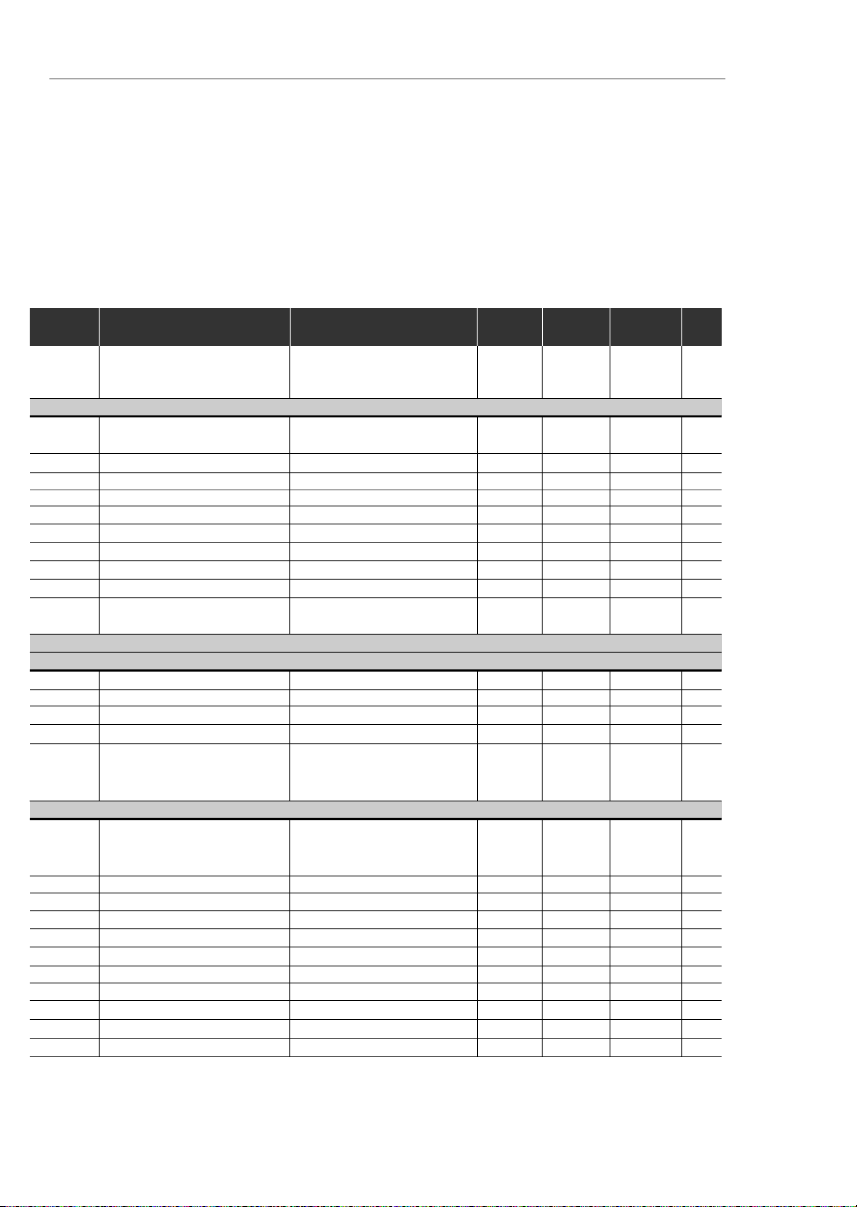
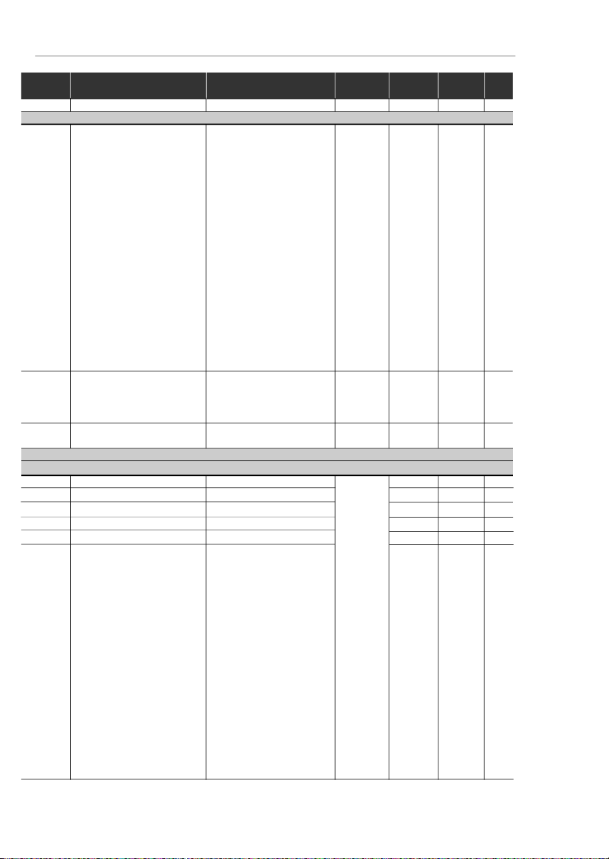
Summary of Revisions
Thetablebelowdescribesallrevisionsmade tothismanual.
Revision
Description
Section
1
First Edition
-
2
Inclusionof the item 3.3 - European
Refer to item 3.3
EMCDirective -Requirements for
ConformingInstallations
3
GeneralRevision
-
4
External Parallel Keypadand
Refer to item 8.3
Fix Kit included and
and8.18
GeneralRevision
5
Descriptionchanged of the
Refer to item 8.5
ParallelCable
for the External Parallel Keypad
Item7.5 (SparePart List) removed
ParameterP536 included
Refer to item 6.3.5
andGeneralRevision
6
GeneralRevision
-
7
Inclusionof new models (22 A, 28 Aand
Refer to item 9.1
33A/200-240 V; 24A and 30 A/380-480V)
Addition of new I/O functions
Refer to item 3.2.5
on the control board
Modificationof circuit breakers table
Refer to item 3.2.3
Modificationof chapter 3
(installationand connections)
Modificationofparameters
Refer to item 4.2.4
incompatibility table
Additionof parameters P253,
Refer to item 6.3
P267and P268
Addition of new functions at parameters
P235, P239, P295and P404
Modificationof factorydefault
Refer to item 6.3.3
valueofparameterP248
Addition of error code E32
Refer to item 7.1
8
GeneralRevision
Inclusion of items into the table of
Refer to item 4.2.4
parametersincompatibility
Changeon the WEG part number
Referto chapter 8
ofthe optional devices
Inclusionof the table containing the
Refer to item 3.1.3.1
airflowrequirementsforpanel mounting
Inclusionof the following optionals:
Referto chapter 8
KRS-485-CFW08,KFB-CO-CFW08,
KFB-DN-CFW08and KAC-120-CFW08
Inclusionof the new versions
Refer to item 2.4
of the control board:A3 and A4
9
TheSleep function wasadded
Referto chapter 6
(parametersP212, P213and P535)
TheAnalogInputDead Zonefunction
wasadded (P233)
TheKDC-24VR-CFW08and
Refer to items 8.9
KDC-24V-CFW08optionmodules
and8.10
wereadded
NewEMC filters wereadded
Refer to item 3.3.4
Noteson the CFW-08 Nema 4X
Referto chapter 2.4
and the 575 V lines were added
Modificationof the gainequation
for the analog inputs
Generalrevision
-

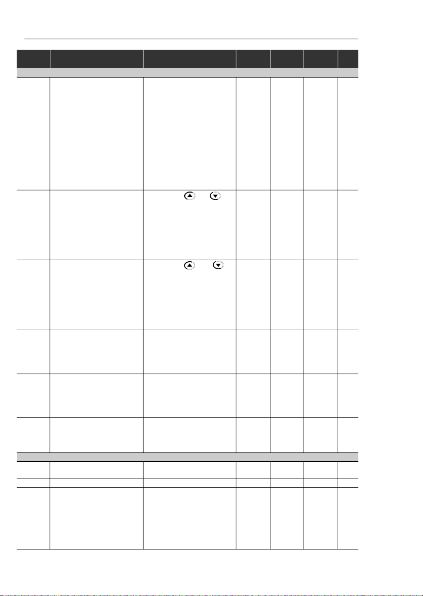
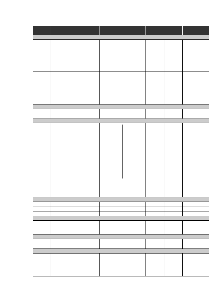
Summary
QuickParameterReference,
Fault and Status Messages
I Parameters
....................................................................
8
II FaultMessages
...........................................................
16
IIIOtherMessages
...........................................................
16
CHAPTER 1
Safety Notices
1.1SafetyNotices in the Manual
.....................................
17
1.2SafetyNotices on theProduct
...................................
17
1.3PreliminaryRecommendations
.................................
17
CHAPTER 2
General Information
2.1AboutthisManual
......................................................
19
2.2Software Version
.......................................................
19
2.3About the CFW-08
....................................................
20
2.4CFW-08Identification
...............................................
24
2.5ReceivingandStoring
...............................................
27
CHAPTER 3
Installation and Connection
3.1MechanicalInstallation
..............................................
28
3.1.1Environment
........................................................
28
3.1.2Mounting Specifications
......................................
28
3.1.3
Positioningand Fixing
........................................
31
3.1.3.1PanelMounting
..........................................
32
3.1.3.2SurfaceMounting
.......................................
33
3.2
ElectricalInstallation
.................................................
33
3.2.1Power/GroundingTerminals
..............................
33
3.2.2
Locationof the PowerTerminals,Grounding
TerminalsandControlTerminalConnections
......
35
3.2.3
Power/GroundingWiringand CircuitBreakers
..
36
3.2.4Power Connections
............................................
37
3.2.4.1
ACInput Connection
................................
39
3.2.4.2
OutputConnections
..................................
40
3.2.4.3
GroundingConnections
............................
40
3.2.5
Signaland Control
Connections
.........................
42
3.2.5.1
DigitalInputsas LowLevelActive
(S1:1 to OFF)
...........................................
46
3.2.5.2
DigitalInput as High LevelActive
(S1:1to ON)
.............................................
47
3.2.6TypicalTerminalConnections
.............................
48
3.3
EuropeanEMCDirective-Requirements
forConformingInstallations
......................................
51
3.3.1Installation
...........................................................
51

Summary
3.3.2Emission and Immunity LevelsDescription
........
52
3.3.3InverterModels and Filters
..................................
54
3.3.4 EMC FiltersCharacteristics
...............................
57
CHAPTER 4
Keypad (HMI) Operation
4.1Keypad(HMI)Description
.........................................
67
4.2Useof the Keypad(HMI)
...........................................
68
4.2.1KeypadOperation
..............................................
69
4.2.2InverterStatus
.....................................................
70
4.2.3Read-OnlyParameters
.......................................
71
4.2.4Parameter Viewing and Programming
...............
71
CHAPTER 5
Start-up
5.1 Pre-Power Checks
....................................................
74
5.2Initial Power-up
..........................................................
74
5.3Start-up
......................................................................
75
5.3.1
Start-upOperationvia Keypad(HMI)-
Type of Control:LinearV/F (P202 = 0)
...............
76
5.3.2
Start-upOperation viaTerminals-
Control Mode: Linear V/F (P202 = 0)
.................
77
5.3.3
Start-upOperation via Keypad -
Control Mode: Vector(P202 = 2)
........................
78
CHAPTER 6
DetailedParameter Description
6.1Symbols...
.................................................................
83
6.2Introduction
................................................................
83
6.2.1Control Modes (V/F and Vector)
.........................
83
6.2.2V/F Control
.........................................................
83
6.2.3VectorControl (VVC)
..........................................
84
6.2.4FrequencyReferenceSources
...........................
85
6.2.5
Commands
.........................................................
88
6.2.6Local/RemoteOperationModes
........................
88
6.3Parameter Listing
......................................................
89
6.3.1
AccessandRead-onlyParameters-
P000 to P099
.....................................................
90
6.3.2Regulation Parameters- P100 to P199
.............
92
6.3.3 Configuration Parameters- P200 to P398
.......
102
6.3.4 Motor Parameters - P399 to P499
...................
128
6.3.5 Special Function Parameters - P500 to P599
..
131
6.3.5.1Introduction
..............................................
131
6.3.5.2Description
..............................................
131
6.3.5.3PID Start-upGuide
...................................
134

Summary
CHAPTER 7
Diagnosticsand Troubleshooting
7.1Faults and PossibleCauses
...................................
141
7.2Troubleshooting
.......................................................
144
7.3ContactingWEG
.....................................................
145
7.4PreventiveMaintenance
..........................................
145
7.4.1CleaningInstructions
.........................................
146
CHAPTER 8
CFW-08Options andAccessories
8.1HMI-CFW08-P
........................................................
149
8.1.1InstructionsforInsertionand Removingof
theHMI-CFW08-P
............................................
149
8.2TCL-CFW08
...........................................................
149
8.3HMI-CFW08-RP
......................................................
150
8.3.1HMI-CFW08-RPInstallation
..............................
150
8.4MIP-CFW08-RP
......................................................
151
8.5 CAB-RP-1, CAB-RP-2, CAB-RP-3, CAB-RP-5,
CAB-RP-7.5, CAB-RP-10
......................................
151
8.6HMI-CFW08-RS
......................................................
151
8.6.1HMI-CFW08-RSInstallation
..............................
152
8.6.2HMI-CFW08-RSStart-up
..................................
152
8.6.3KeypadCopyFunction
.....................................
153
8.7MIS-CFW08-RS
......................................................
153
8.8 CAB-RS-1, CAB-RS-2, CAB-RS-3, CAB-RS-5,
CAB-RS-7.5, CAB-RS-10
......................................
153
8.9 KDC-24VR-CFW08
................................................
154
8.10 KDC-24V-CFW08
.................................................
155
8.11KCS-CFW08
.........................................................
156
8.11.1
InstructionsforKCS-CFW08
InsertionandRemoval
.....................................
157
8.12 KSD-CFW08
........................................................
157
8.13KRS-485-CFW08
.................................................
158
8.14 KFB-CO-CFW08
..................................................
159
8.15 KFB-DN-CFW08
..................................................
160
8.16 KAC-120-CFW08, KAC-120-CFW08-N1M1
KAC-120-CFW08-N1M2
......................................
162
8.17 KMD-CFW08-M1
..................................................
163
8.18KFIX-CFW08-M1, KFIX-CFW08-M2
....................
164
8.19KN1-CFW08-M1, KN1-CFW08-M2
......................
165
8.20RFI Filter
...............................................................
166
8.21Line Reactor
..........................................................
167
8.21.1Application Criteria
.......................................
167
8.22 Load Reactor
........................................................
170
8.23Dynamic Braking
...................................................
171
8.23.1ResistorSizing
..............................................
171
8.23.2Installation
.....................................................
172
8.24SerialCommunication
...........................................
173

Summary
8.24.1Introduction
....................................................
173
8.24.2RS-485andRS-232InterfacesDescription
.
174
8.24.2.1RS-485
..............................................
175
8.24.2.2RS-232
..............................................
176
8.24.3Definitions
.....................................................
176
8.24.3.1Used Terms
.......................................
176
8.24.3.2Parameter/Variables Resolution
........
177
8.24.3.3Character Format
..............................
177
8.24.3.4Protocol
.............................................
177
8.24.3.5Execution and MessageTest
.............
180
8.24.3.6MessageSequence
..........................
180
8.24.3.7 Variable Code
...................................
180
8.24.4Message Examples
......................................
181
8.24.5 Variablesand Errors of the Serial
Communication
............................................
181
8.24.5.1 Basic Variables
.................................
181
8.24.5.2 Message Examples with Basic
Variables
............................................
184
8.24.5.3ParametersRelatedtotheSerial
Communication
...................................
185
8.24.5.4ErrorsRelated to the Serial
Communication
.................................
186
8.24.6TimeforRead/Write of Messages
................
186
8.24.7Physical Connection RS-232andRS-485
....
187
8.25Modbus-RTU
.........................................................
188
8.25.1IntroductiontoModbus-RTUProtocol
...........
188
8.25.1.1Transmission Modes
.........................
188
8.25.1.2Message StructureinRTU Mode
......
188
8.25.2Operation oftheCFW-08inthe
Modbus-RTUNetwork
..................................
191
8.25.2.1RS-232 and RS-485 Interface
Description
.......................................
191
8.25.2.2 InverterConfigurationinthe
Modbus-RTU Network
.....................
191
8.25.2.3AccesstotheInverterData
...............
192
8.25.3Detailed Function Description
......................
195
8.25.3.1Function 01 - Read Coils
..................
195
8.25.3.2Function 03-Read Holding Register
196
8.25.3.3Function 05 - WriteSingle Coil
.........
197
8.25.3.4Function 06-Write SingleRegister
..
198
8.25.3.5Function 15 -Write Multiple Coils
......
198
8.25.3.6Function 16 - WriteMultipleRegisters
199
8.25.3.7Function 43 - Read Device
Identification
.....................................
200
8.25.4Modbus-RTUCommunicationErrors
............
202
8.25.4.1 Error Messages
...............................
203

Summary
CHAPTER 9
TechnicalSpecifications
9.1
Power Data
..............................................................
204
9.1.1 200-240 V Power Supply
..................................
204
9.1.2 380-480 V Power Supply
..................................
205
9.2Electronics/GeneralData
........................................
208
9.3WEG Standard IV-PoleMotorData
.........................
209
8
CFW-08 - QUICK PARAMETER REFERENCE
Software: V5.2X
Application:
Model:
SerialNumber:
Responsible:
Date: / / .
I.Parameters
QUICK PARAMETER REFERENCE, FAULT AND STATUS MESSAGES
Parameter
Function
Adjustable Range
Factory
Unit
User
Page
Setting
Setting
P000
ParameterAccess
0 to 4 = Read
0
-
90
5 = Alteration
6 to 999 = Read
READONL
Y
P
ARAMETERS-
P002to P099
P002
FrequencyProportionalValue
0 to 6553
-
-
90
(P208xP005)
P003
MotorOutput Current
0 to 1.5xI
nom
-
A
90
P004
DCLink Voltage
0 to 862
-
V
90
P005
Motor Output Frequency
0.00 to 300.0
-
Hz
90
P007
MotorOutput Voltage
0 to 600
-
V
90
P008
HeatsinkTemperature
25 to 110
-
°C
91
P009
(1)
MotorTorque
0.0 to 150.0
-
%
91
P014
Last Fault
00 to 41
-
-
91
P023
SoftwareVersion
x . y z
-
-
91
P040
PID Process Variable
0 to 6553
-
-
91
(Value% x P528)
REGULA
TIONPARAMETERS -
P100 to P199
Ramps
P100
AccelerationTime
0.1 to 999
5.0
s
92
P101
DecelerationTime
0.1 to 999
10.0
s
92
P102
Ramp 2 AccelerationTime
0.1 to 999
5.0
s
92
P103
Ramp2 DecelerationTime
0.1 to 999
10.0
s
92
P104
S Ramp
0= Inactive
0
-
92
1 = 50 %
2 = 100 %
Frequency Reference
P120
DigitalReferenceBackup
0= Inactive
1
-
93
1 = Active
2 = Backup by P121
P121
KeypadReference
P133 to P134
3.00
Hz
93
P122
JOGSpeedReference
0.00 to P134
5.00
Hz
94
P124
MultispeedReference1
P133 to P134
3.00
Hz
94
P125
MultispeedReference2
P133 to P134
10.00
Hz
94
P126
MultispeedReference3
P133 to P134
20.00
Hz
94
P127
MultispeedReference4
P133 to P134
30.00
Hz
95
P128
MultispeedReference5
P133 to P134
40.00
Hz
95
P129
MultispeedReference6
P133 to P134
50.00
Hz
95
P130
MultispeedReference7
P133 to P134
60.00
Hz
95
P131
MultispeedReference8
P133 to P134
66.00
Hz
95

9
CFW-08 - QUICK PARAMETER REFERENCE
Parameter
Function
Adjustable Range
Factory
Unit
User
Page
Setting
Setting
(*)
The factory default of parameter P136 depends on the inverter model as follows:
- models 1.6-2.6-4.0-7.0 A/200-240 V and 1.0-1.6-2.6-4.0 A/380-480 V: P136 = 5.0 %;
- models 7.3-10-16 A/200-240 V and 2.7-4.3-6.5-10 A/380-480 V: P136 = 2.0 %;
- models 22-28-33 A/200-240 V and 13-16-24-30 A/380-480 V: P136 = 1.0 %.
Speed Limits
P133
Minimum Frequency(F
min
)
0.00 to P134
3.00
Hz
95
P134
MaximumFrequency (F
max
)
P133 to 300.0
66.00
Hz
96
V/F Control
P136
(2) (*)
ManualTorque Boost
0.0 to 30.0
5.0 or
%
96
(IxRCompensation)
2.0 or
1.0
(*)
P137
(2)
AutomaticTorqueBoost
0.00 to 1.00
0.00
-
97
(AutomaticIxR Compensation)
P138
(2)
SlipCompensation
0.0 to 10.0
0.0
%
97
P142
(2) (3)
Maximum Output Voltage
0 to 100
100
%
98
P145
(2) (3)
FieldWeakening
P133 to P134
50.00 Hz or
Hz
98
Frequency(F
nom
)
60.00 Hz
depending
on the
market
DC Link Voltage Regulation
P151
DCLink VoltageRegulation
200 V models: 325 to 410
380
V
99
Level
400 V models: 564 to 820
780
Overload Current
P156
MotorOverloadCurrent
0.2xI
nom
to 1.3xI
nom
1.2xP401
A
100
Current Limitation
P169
MaximumOutput Current
0.2xI
nom
to 2.0xI
nom
1.5xP295
A
101
Flux Control
P178
(1)
Rated Flux
50.0 to 150
100
%
101
CONFIGURA
TIONPARAMETERS - P200
to
P398
Generic Parameters
P202
(3)
ControlMode
0 = Linear V/F Control
0
-
102
(Scalar)
1 = Quadratic V/F Control
(Scalar)
2 = S
ensorlessVectorControl
P203
(3)
SpecialFunction Selection
0 = No function
0
-
103
1 = PID Regulator
P204
(3)
Load Factory Setting
0 to 4 = No Function
0
-
104
5 = Loads Factory Default
P205
DisplayDefault Selection
0 = P005
2
-
104
1 = P003
2 = P002
3 = P007
4, 5 = Not Used
6 = P040
P206
Auto-ResetTime
0 to 255
0
s
104
P208
ReferenceScale Factor
0.00 to 99.9
1.00
-
104
P212
Frequencyto Enable the Sleep 0.00 to P134
0.00
Hz
105
Mode
P213
Time Delayto Activate the
0.1 to 999
2.0
s
105
SleepMode
P215
(3) (4)
Keypad Copy Function
0 = Not Used
0
-
106
1 = Copy (inverter
keypad)
2= Paste (keypad
inverter)
P219
(3)
SwitchingFrequency
0.00 to 25.00
6.00
Hz
107
ReductionPoint
10
CFW-08 - QUICK PARAMETER REFERENCE
Parameter
Function
Adjustable Range
Factory
Unit
User
Page
Setting
Setting
(**)
Only available on the control board A2 (refer to item 2.4). For programming instructions, please, refer to the parameter P235 detailed
description.
Local/Remote Definition
P220
(3)
Local/Remote
0 = Always Local
2
-
108
Selection Source
1 = Always Remote
2 =HMI-CFW08-P or
HMI-CFW08-RPKeypad
(default:local)
3 =HMI-CFW08-P or
HMI-CFW08-RPKeypad
(default:remote)
4 = DI2 to DI4
5=
SerialorHMI-CFW08-RS
Keypad(default: local)
6=
SerialorHMI-CFW08-RS
Keypad(default:remote)
P221
(3)
FrequencyLocalReference
0 = Keypad and
0
-
109
Selection
1 = AI1
2, 3 = AI2
4 = E.P.
5 = Serial
6 = Multispeed
7 = Add AI
0
8 = Add AI
P222
(3)
FrequencyRemoteReference
0 = Keypad and
1
-
109
Selection
1 = AI1
2, 3 = AI2
4 = E.P.
5 = Serial
6 = Multispeed
7 = Add AI
0
8 = Add AI
P229
(3)
LocalCommand Selection
0 =HMI-CFW08-P or
0
-
109
HMI-CFW08-RPKeypad
1 = Terminals
2 = Serial or
HMI-CFW08-RSKeypad
P230
(3)
RemoteCommand Selection
0 =HMI-CFW08-P or
1
-
109
HMI-CFW08-RPKeypad
1 = Terminals
2 = Serial or
HMI-CFW08-RSKeypad
P231
(3)
Forward/ReverseSelection
0 = Forward
2
-
110
- Local and Remote
1= Reverse
2 = Commands
3 = DIx
Analog Input (s)
P233
AnalogInputDead Zone
0= Inactive
1
-
110
1 = Active
P234
AnalogInputAI1 Gain
0.00 to 9.99
1.00
-
111
P235
(3) (5)
Analog Input AI1 Function
0 = (0 to 10) V/(0 to 20) mA /
0
-
112
(-10 to +10) V
(**)
1 = (4 to 20) mA
2 = DI5 PNP
3 = DI5 NPN
4= DI5 TTL
5 = PTC

11
CFW-08 - QUICK PARAMETER REFERENCE
Parameter
Function
Adjustable Range
Factory
Unit
User
Page
Setting
Setting
P236
AnalogInputAI1 Offset
-999 to +999
0.0
%
113
P238
(6)
AnalogInputAI2 Gain
0.00 to 9.99
1.00
-
113
P239
(3)(5)(6)
Analog Input AI2 Function
0 = (0 to 10) V/(0 to 20) mA/
0
-
113
(-10 to +10) V
(**)
1 = (4 to 20) mA
2 = DI6 PNP
3 = DI6 NPN
4= DI6 TTL
5 = PTC
P240
(6)
AnalogInputAI2 Offset
-999 to +999
0.0
%
113
P248
Analog Inputs Filter
0 to 200
10
ms
113
TimeConstant
Analog Output
P251
(6)
AnalogOutput
0 = Output Frequency (Fs)
0
-
114
AO Function
1 = InputReference (Fe)
2 = Output Current (Is)
3, 5, 8 = Not Used
4 = MotorTorque
6 = Process Variable (PID)
7 =Active Current
9 = PID Setpoint
P252
(6)
Analog Output AO Gain
0.00 to 9.99
1.00
-
114
P253
Analog OutputAO Signal
0 = (0 to 10) V/(0 to 20) mA
0
-
114
1 = (4 to 20) mA
Digital Inputs
P263
(3)
Digital Input DI1Function
0 = No Function or General
0
-
115
Enable
1 to 7 and 10 to 12 =
GeneralEnable
8 = Forward Run
9 = Start/Stop
13 = FWD Run Using
Ramp2
14 = On
P264
(3)
Digital Input DI2Function
0= Forward/Reverse
0
-
115
1 = Local/Remote
2 to 6 and 9 to 12 = Not
U
sed
7 = Multispeed (MS2)
8= Reverse
13 = REV Run - Ramp 2
14 = Off
P265
(3) (7)
Digital InputDI3 Function
0= Forward/Reverse
10
-
115
1 = Local/Remote
2 = GeneralEnable
3 = JOG
4 = No External Fault
5 = Increase E.P.
6 = Ramp 2
7 = Multispeed (MS1)
8 = No Function or
Start/Stop
9 = Start/Stop
10 = Reset
(**)
Only available on the control board A2 (refer to item 2.4). For programming instructions, please, refer to the parameter P235 detailed
description.

12
CFW-08 - QUICK PARAMETER REFERENCE
Parameter
Function
Adjustable Range
Factory
Unit
User
Page
Setting
Setting
11,12 = Not Used
13 = Flying Start Disable
14 = Multispeed (MS1)
UsingRamp 2
15 = Manual/Automatic (PID)
16 = Increase E.P. with
Ramp2
P266
(3)
Digital InputDI4 Function
0= Forward/Reverse
8
-
115
1 = Local/Remote
2 = GeneralEnable
3 = JOG
4 = No External Fault
5 = Decrease E.P.
6 = Ramp 2
7 = Multispeed (MS0)
8 = Not Used or
Start/Stop
9 = Start/Stop
10 = Reset
11,12, 14 and 15 = Not Used
13 = Flying Start Disable
16 = Decrease E.P. with
Ramp2
P267
(3) (5)
Function of the Digital
0 = FWD/REV
11
-
115
InputDI5 (only displayed
1 = Local/Remote
when P235 = 2, 3 or 4)
2 = GeneralEnable
3 = JOG
4 = No External Fault
5 = Increase E.P.
6 = Ramp 2
7 = Multispeed (MS2)
8 =
No Function
or Start/Stop
9 = Start/Stop
10 = Reset
11and 12 = Not Used
13 = Disables Flying Start
14 and 15 = Not Used
16 = Increase E.P. with
Ramp2
P268
(3) (5) (6)
Function of the Digital
0 = FWD/REV
11
-
115
InputDI6 (only displayed
1 = Local/Remote
when P239 = 2, 3 or 4)
2 = GeneralEnable
3 = JOG
4 = No External Fault
5 = Decrease E.P.
6 = Ramp 2
7 = Not Used
8 =
No Function
or Start/Stop
9 = Start/Stop
10 = Reset
11and 12 = Not Used
13 = Disables Flying Start
14 and 15 = Not Used
16 = Decrease E.P. with
Ramp2
13
CFW-08 - QUICK PARAMETER REFERENCE
Parameter
Function
Adjustable Range
Factory
Unit
User
Page
Setting
Setting
(*) It is not possible to set P297 = 7 (15 kHz) in vector control mode(P202 = 2) or when the external serial keypad (HMI-CFW08-RS) is used.
According
to the
inverter
model
DigitalOutput(s)
P277
(3)
RelayOutput RL1 Function
0 = Fs > Fx
7
-
120
1 = Fe > Fx
2 = Fs = Fe
3 = Is>Ix
4 and 6 = Not Used
5 = Run
7 = No Fault
P279
(3) (6)
RelayOutput RL2 Function
0 = Fs > Fx
0
-
120
1 = Fe > Fx
2 = Fs = Fe
3 = Is > Ix
4 and 6 = Not Used
5 = Run
7 = No Fault
Fx and Ix
P288
Fx Frequency
0.00 to P134
3.00
Hz
122
P290
IxCurrent
0 to 1.5xI
nom
1.0xI
nom
A
122
Inverter Data
P295
(3)
RatedInverter
300 = 1.0 A
-
122
Current(I
nom
)
301 = 1.6 A
302 = 2.6 A
303 = 2.7 A
304 = 4.0 A
305 = 4.3 A
306 = 6.5 A
307 = 7.0 A
308 = 7.3 A
309 = 10 A
310 = 13 A
311= 16A
P297
(3)
SwitchingFrequency
4 = 5.0
4
kHz
122
5 = 2.5
6 = 10
7 = 15
(*)
DC Braking
P300
DCBraking Time
0.0 to 15.0
0.0
s
124
P301
DC Braking StartFrequency
0.00 to 15.00
1.00
Hz
124
P302
DCBraking Current
0.0 to 130
0.0
%
124
Skip Frequencies
P303
Skip Frequency 1
P133 to P134
20.00
Hz
125
P304
Skip Frequency 2
P133 to P134
30.00
Hz
125
P306
Skip BandRange
0.00 to 25.00
0.00
Hz
125
Serial Communication Interface I
P308
(3)
InverterAddress
1 to 30 (Serial WEG)
1
-
125
1to 247(Modbus-RTU)
Flying Start and Ride-Through
P310
(3)
FlyingStartandRide-Through
0= Inactive
0
-
126
1 = Flying Start
2 = Flying Start and
Ride-Through
3= Ride-Through
312 = 22 A
313 = 24 A
314 = 28 A
315 = 30 A
316 = 33 A
14
CFW-08 - QUICK PARAMETER REFERENCE
Parameter
Function
Adjustable Range
Factory
Unit
User
Page
Setting
Setting
P311
VoltageRamp
0.1 to 10.0
5.0
s
126
Serial Communication Interface II
P312
(3)
SerialInterface Protocol
0 = Serial WEG
0
-
127
1 = Modbus-RTU9600 bps
without parity
2 = Modbus-RTU9600 bps
with odd parity
3 = Modbus-RTU9600 bps
witheven parity
4 = Modbus-RTU19200 bps
without parity
5 = Modbus-RTU19200 bps
with odd parity
6 = Modbus-RTU19200 bps
witheven parity
7 = Modbus-RTU38400 bps
without parity
8 = Modbus-RTU38400 bps
with odd parity
9 = Modbus-RTU38400 bps
witheven parity
P313
SerialInterfaceWatchdog
0 = Disabling by ramp
2
-
127
Action
1 = General disable
2 = Shows only E28
3 = Goes to local mode
P314
SerialInterfaceWatchdog
0.0= Disables the function
0.0
s
128
Timeout
0.1to 99.9 = Setvalue
MOTORPARAMETERS- P399 to P499
Rated Parameters
P399
(1) (3)
Rated MotorEfficiency
50.0 to 99.9
%
128
P400
(1) (3)
RatedMotor Voltage
0 to 600
V
128
P401
RatedMotorCurrent
0.3xP295 to 1.3xP295
A
128
P402
(1)
RatedMotor Speed
0 to 9999
rpm
129
P403
(1) (3)
Rated Motor Frequency
0.00 to P134
Hz
129
P404
(1) (3)
RatedMotor Power
0 = 0.16 HP / 0.12 kW
-
129
1 = 0.25 HP / 0.18 kW
2 = 0.33 HP / 0.25 kW
3 = 0.50 HP / 0.37 kW
4 = 0.75 HP / 0.55 kW
5 = 1 HP / 0.75 kW
6 = 1.5 HP / 1.1 kW
7 = 2 HP / 1.5 kW
8 = 3 HP / 2.2 kW
9 = 4 HP / 3.0 kW
10 = 5 HP / 3.7 kW
11 = 5.5 HP / 4.0 kW
12 = 6 HP / 4.5 kW
13 = 7.5 HP / 5.5 kW
14 = 10 HP / 7.5 kW
15 = 12.5 HP / 9.2 kW
16 = 15 HP / 11.2 kW
17 = 20 HP / 15.0 kW
According
to the
inverter
model
(motor
matched
to the
inverter-
referto
item 9.3)
and sales
market

15
CFW-08 - QUICK PARAMETER REFERENCE
Parameter
Function
Adjustable Range
Factory
Unit
User
Page
Setting
Setting
Notesfound on the Quick ParameterReference:
(1)
This parameter is only displayedin vector mode (P202 = 2).
(2)
This parameter is only displayed in scalar mode P202 = 0 or 1.
(3)
Thisparametercanbechangedonlywhen the inverter is disabled (stopped motor).
(4)
Thisparameteris onlyavailable withHMI-CFW08-RS.
(5)
Theanaloginputvalueisrepresentedbyzerowhenitis notconnectedtoan externalsignal.
In order to use an analog input as a digital input with NPN logic (P235 or P239 = 3), it is
necessary to connect a 10 k
resistor from terminal 7 to 6 (AI1) or 8 (AI2) of the control
terminalstrip.
(6)
Thisparameteris only available in the CFW-08Plusversion.
(7)
Theparameter value changesautomaticallywhenP203 = 1.
P407
(3)
RatedMotor Power
0.50 to 0.99
-
130
Factor
Measured Parameters
P408
(1) (3)
RunSelf-Tuning
0 = No
0
-
130
1 = Yes
P409
(3)
Motor Stator Resistance
0.00 to 99.99
130
SPECIAL FUNCTION - P500 to P599
PID Regulator
P520
PIDProportionalGain
0.000 to 7.999
1.000
-
138
P521
PIDIntegralGain
0.000 to 9.999
1.000
-
138
P522
PIDDifferentialGain
0.000 to 9.999
0.000
-
138
P525
Setpoint (Via Keypad) of the
0.00 to 100.0
0.00
%
138
PIDRegulator
P526
Process VariableFilter
0.01 to 10.00
0.10
s
138
P527
PIDAction
0 = Direct
0
-
138
1= Reverse
P528
Process Variable
0.00 to 99.9
1.00
-
139
Scale Factor
P535
Wake up Band
0.00 to 100.00
1.00
%
139
P536
Automatic Setting of P525
0 = Active
0
-
140
1= Inactive
Accordingto
theinverter
model
(referto
item 9.3)
Accordingto
theinverter
model

16
CFW-08 - QUICK PARAMETER REFERENCE
Display
Description
Page
E00
Outputovercurrent/short-circuit
/outputgroundfault
141
E01
DClinkovervoltage
141
E02
DClink undervoltage
142
E04
Overtemperatureat the powerheatsink
orin the
142
inverterinternalair
E05
Outputoverload (Ixt function)
142
E06
Externalfault
142
E08
CPUerror(Watchdog)
142
E09
Programmemoryerror (Checksum)
142
E10
Keypadcopy function error
142
E14
S
elf-tuningroutine (estimation of the motor
142
parameters)error
E22,
E25
,
Serialcommunication error
142
E2
6 andE27
E24
Programmingerror
142
E28
Serialinterface Watchdog timeout error
143
E31
Keypadconnectionfault(HMI-CFW08-RS)
143
E32
Motorovertemperature(externalPTC)
143
E41
Self-diagnosisfault
143
II.FaultMessages
III.OtherMessages
Display
Description
rdy
Inverteris readyto be enabled
Sub
Powersupply voltage is too lowfor the inverter
operation(undervoltage)
dcbr
InverterinDC brakingmode
auto
Inverterisrunningself-tuningroutine
copy
Keypadcopy function in progress (only available in
theHMI-CFW08-RS) -inverter to keypad
past
Keypadcopy function in progress (only available in
theHMI-CFW08-RS) -keypadtoinverter
Srdy
Inverterin the sleep rdymode
17
CHAPTER1
SAFETYNOTICES
This Manual contains necessary information for the correct
useof the CFW-08frequencyinverter.
This Manual was developed for qualified personnel with
suitabletrainingandtechnicalqualificationtooperatethistype
ofequipment.
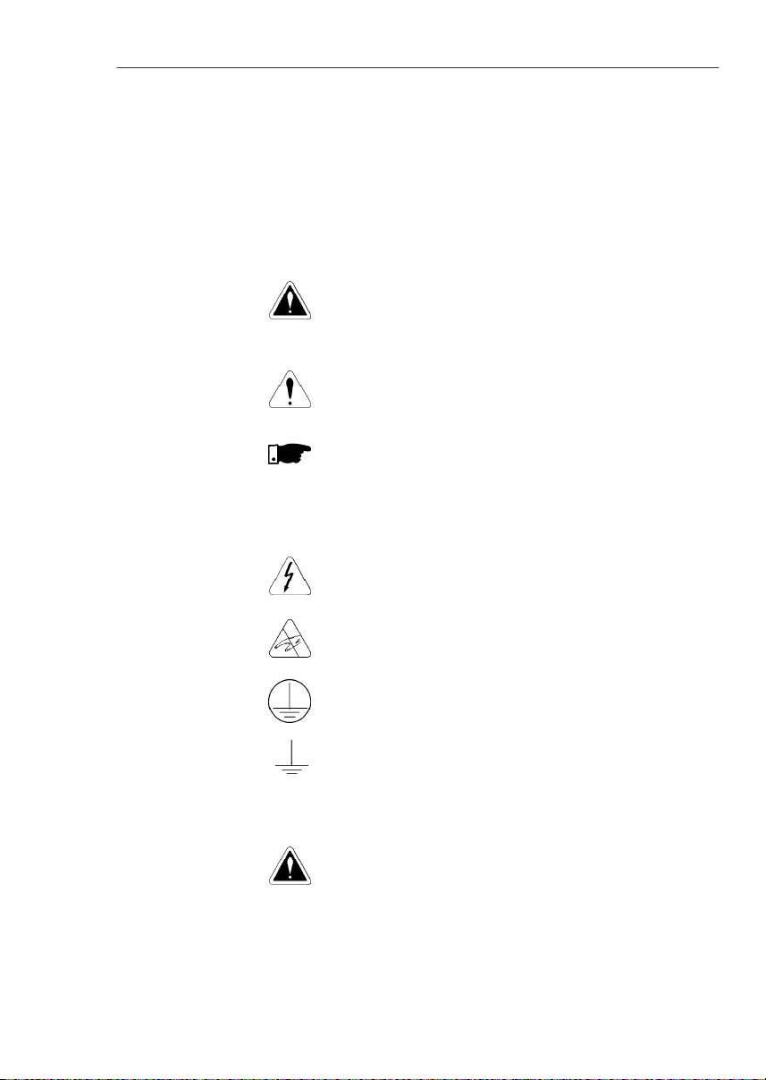
Thefollowingsafetynotices are usedinthismanual:
DANGER!
Ifthe recommendedsafetynoticesare notstrictlyobserved,it
canleadtoseriousorfatalinjuriesofpersonneland/ormaterial
damage.
ATTENTION!
Failureto observe the recommended safety procedures can
lead to material damage.
NOTE!
This notice provides important information for the proper
understandingandoperationof the equipment.
Thefollowingsymbolsmaybeattachedtotheproduct,serving
assafetynotice:
High Voltages.
Componentssensitive to electrostaticdischarge.Donot
touch them without proper grounding procedures.
Mandatory connection to ground protection (PE).
Shield connection to ground.
DANGER!
Only qualified personnel should plan or implement the
installation, start- up, operation and maintenance of this
equipment. Personnel must review entire Manual before
attemptingto install, operateortroubleshootthe CFW-08.
Thesepersonnel must follow all safety instructions included
inthismanualand/or definedbylocal regulations.
Failure to comply with these instructions may result in
personnelinjuryand/orequipmentdamage.
1.3
PRELIMINARY
RECOMMENDA
TIONS
1.2
SAFETYNOTICES
ONTHE PRODUCT
1.1
SAFETYNOTICESIN
THEMANUAL
18
CHAPTER 1 - SAFETY NOTICES
NOTE!
Inthis manual,qualified personnelare definedas peoplethatare
trainedto:
1.
Install,ground, powerupandoperatethe CFW-08according
tothis manual andthe local required safetyprocedures;
2.
Useofsafetyequipment according to the local regulations;
3.
Administer First Aid.
DANGER!
Theinvertercontrol circuit (ECC3, DSP) and the HMI-CFW08-P
arehighvoltagecircuitsand are notgrounded.
DANGER!
Always disconnect the supply voltage before touching any
electricalcomponentinsidethe inverter.
Many components are charged with high voltage and/or in
movement (fans), even after the incomingAC power supply has
beendisconnectedor switchedOFF. Waitatleast10 minutesfor
thetotal discharge of the power capacitors.
Alwaysconnecttheframeof the equipmentto theground(PE)at
thesuitable connectionpoint.
ATTENTION!
All electronic boards have components that are sensitive to
electrostatic discharges. Never touch any of the electrical
components or connectors without following proper grounding
procedures. If necessary to do so, touch the properly grounded
metallicframe or use a suitable ground strap.
NOTE!
Inverterscan interferewithotherelectronicequipment.Inorderto
reduce this interference, adopt the measures recommended in
chapter3-InstallationandConnection.
NOTE!
ReadthisentiremanualbeforeinstallingoroperatingtheCFW-08.
Do not apply high voltage(high pot)test on theinverter!
If this test is necessary, contact WEG.

19
Thischapterdefines thecontentsand purposesof thismanu-
al and describes the main characteristics of the
CFW-08
frequency inverter. Identification, receiving inspections and
storagerequirementsare also provided.
Thismanualis divided into 9 chapters,providinginformation
to the user on how receive, install, start-up and operate the
CFW-08.
Chapter 1 -
Safetynotices.
Chapter 2 -
Generalinformationandreceivingthe CFW-08.
Chapter 3 -
RFIfilters,mechanical and electrical installation
(powerand controlcircuit).
Chapter 4 -
Using the keypad (Human Machine Interface -
HMI).
Chapter
5 -
Start-upandstepsto follow.
Chapter
6 -
Setup and read only parameters detailed
description.
Chapter
7 -
Solving problems, cleaning instructions and
preventivemaintenance.
Chapter 8 -
CFW-08 optional devices description, technical
characteristicsand installation.
Chapter 9 -
CFW-08ratings,tablesandtechnicalinformation.
This manual provides information for the correct use of the
CFW-08. This frequency inverter is very flexible and allows
the operation in many different modes as described in this
manual.
AstheCFW-08canbeappliedin severalways,itisimpossible
todescribehere all oftheapplicationpossibilities.WEGdoes
not accept any responsibility when the CFW-08 is not used
accordingto thismanual.
Nopartofthismanualmaybereproducedinanyform,without
thewrittenpermissionofWEG.
It is important to note the software version installed in the
CFW-08, since it definesthefunctionsand the programming
parameters of the inverter.
This manual refers to the software version indicated on the
insidecover.Forexample,theversion3.0Xappliestoversions
3.00 to 3.09, where “X” is a variable that will change due to
minor software revisions. The operation of the CFW-08 with
these software revisions are still covered by this version of
themanual.
Thesoftwareversion can be read in theparameterP023.
GENERALINFORMATION
2.1
ABOUTTHIS
MANUAL
2.2
SOFTWARE
VERSION
CHAPTER2

20
CHAPTER 2 - GENERAL INFORMATION
2.3
ABOUTTHECFW-08
TheCFW-08frequencyinverterprovidestwocontroloptions:
vector control (VVC: voltage vector control) or V/F (scalar);
bothtypesof control can be setaccordingtotheapplication.
Inthevectorcontrolmode,themotorperformanceisoptimized
relatingto torque and speed regulation.
The"Self-Tuning"function,availableinvectorcontrol,permits
the automatic setting of the inverter parameter from the
identification(alsoautomatic)of the parametersof the motor
connectedatthe inverteroutput.
The V/F (scalar) mode is recommended for simpler
applicationssuchas pumpandfandrives.In thesecasesone
can reduce the motor and inverter losses by using the
"QuadraticV/F" option, thatresultsinenergysaving.
TheV/Fmodeisalsousedwhenmorethanonemotorshould
be driven simultaneously by one inverter (multimotor
application).
For power ratings and furthertechnical information, refer to
Chapter9.
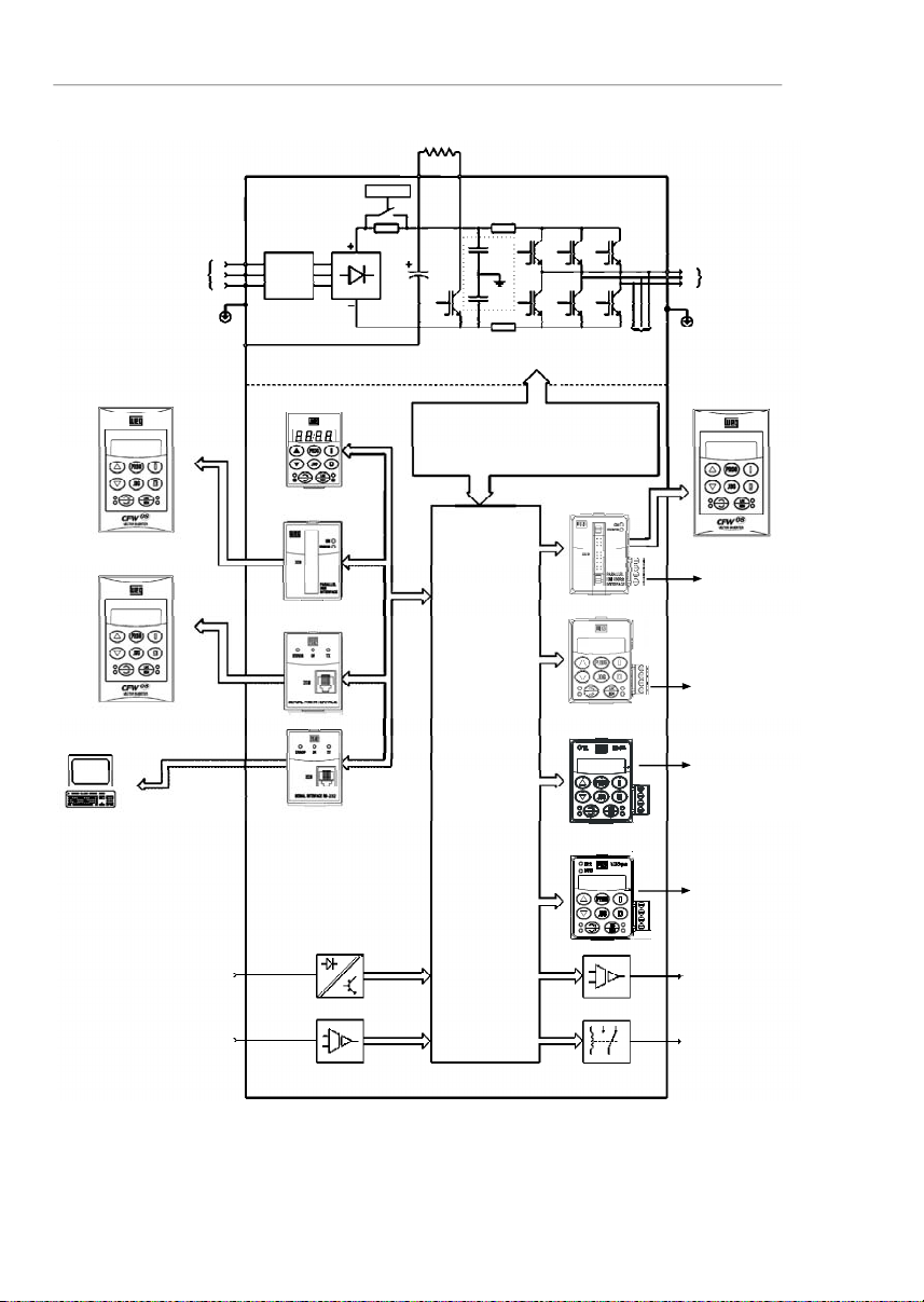
The block diagram below gives a general overview of the
CFW-08.
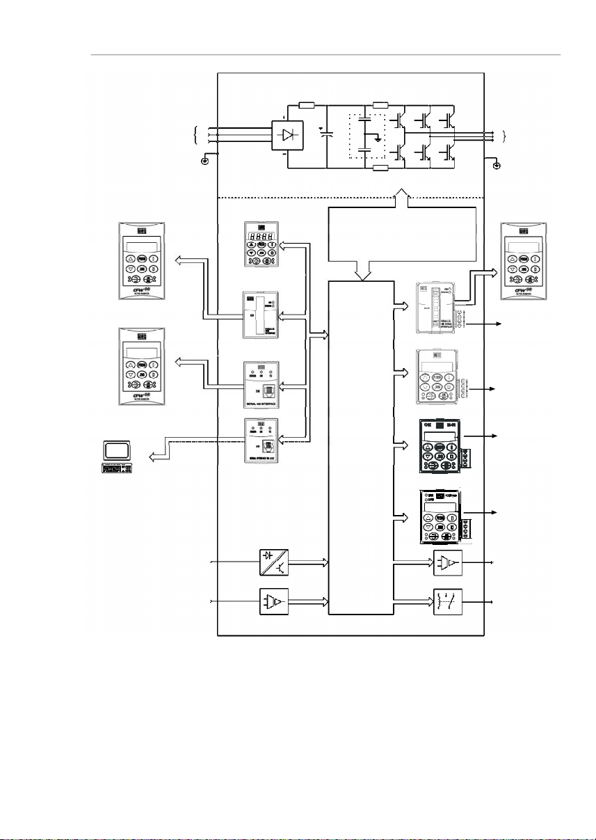
21
CHAPTER 2 - GENERAL INFORMATION
Figure 2.1
- Block diagram for the models:
1.6-2.6-4.0-7.0A/200-240V and 1.0-1.6-2.6-4.0A/380-480V
Power
Supply
R
S
T
PE
HMI-CFW08-RS
PC-Software
SuperDrive
Analog
Inputs
(AI1andAI2)
Digital
Inputs
(DI1to DI4)
Interface
RS-232KCS-CFW08
Interface
MIS-CFW08-RS
or
HMI-CFW08-P
POWER
CONTROL
POWER SUPPLIESAND
CONTROL/POWER
INTERFACES
"ECC3"
CONTROL
BOARD
WITHDSP
Motor
U
V
W
Rsh2
Rsh1
NTC
PE
RFIFilter
HMI-CFW08-RP
Interface
MIP-CFW08-RP
or
or
Analog
Output
(AO)
Relay
Output
(RL1andRL2)
CANopen
or
DeviceNet
KRS-485
KFB-COorKFB-DN
RS-485
24 V Power
Supply
24 V Power
Supply
HMI-CFW08-RP
KDC-24VR-CFW08
KDC-24V-CFW08
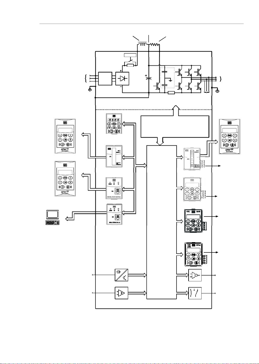
22
CHAPTER 2 - GENERAL INFORMATION
Figure 2.2
- Block diagram for the models:
7.3-10-16-22 A/200-240Vand 2.7-4.3-6.5-10-13-16A/380-480V
Note:
models 16 A and 22 A/200-240 V are not fitted with optional RFI filter.
Redede
Alimentação
R
S
T
RFI
Suppressor
Filter
(optional)
HMI-CFW08-RS
PC-Software
SuperDrive
Analog
Inputs
(AI1andAI2)
Digital
Inputs
(DI1to DI4)
Interface
RS-232KCS-CFW08
Interface
MIS-
CFW08-RS
HMI-CFW08-P
POWER
CONTROL
POWER SUPPLIESAND CONTROL
/POWERINTERFACES
"ECC3"
CONTROL
BOARD
WITHDSP
Motor
U
V
W
Rsh2
Rsh1
RPC
Pré-Carga
Braking Resistor
(Externaland Optional)
BR
+UD
PE
-UD
Voltage
Feedback
PE
or
or
RFI
Filter
or
Interface
MIP-
CFW08-RP
HMI-CFW08-RP
Analog
Output
(AO)
Relay
Output
(RL1andRL2)
CANopen
or
DeviceNet
KRS-485
KFB-COorKFB-DN
RS-485
24 V Power
Supply
24 V Power
Supply
HMI-CFW08-RP
KDC-24VR-CFW08
KDC-24V-CFW08
23
CHAPTER 2 - GENERAL INFORMATION
Figure 2.3
- Block diagram for the models:
28-33A/200-240 V and24-30 A/380-480 V
Note:
models 28 A and 33 A/200-240 V are not fitted with optional RFI filter.
Power
Supply
R
S
T
RFI
Suppressor
Filter
(optional)
HMI-CFW08-RS
PC-Software
SuperDrive
Analog
Inputs
(AI1andAI2)
Digital
Inputs
(DI1to DI4)
Interface
RS-232KCS-CFW08
Interface
MIS-
CFW08-RS
HMI-CFW08-P
POWER
CONTROL
POWER SUPPLIESAND
CONTROL/POWER
INTERFACES
"ECC3"
CONTROL
BOARD
WITHDSP
Motor
U
V
W
Rsh1
RPC
Pré-Carga
Braking Resistor
(optional)
BR
DCR
PE
-UD
Voltage
Feedback
PE
or
or
RFI
Filter
or
Interface
MIP-
CFW08-RP
HMI-CFW08-RP
DCLink Inductor
(optional)
+UD
Analog
Output
(AO)
Relay
Output
(RL1andRL2)
CANopen
or
DeviceNet
KRS-485
KFB-COorKFB-DN
RS-485
24 V Power
Supply
24 V Power
Supply
HMI-CFW08-RP
KDC-24VR-CFW08
KDC-24V-CFW08
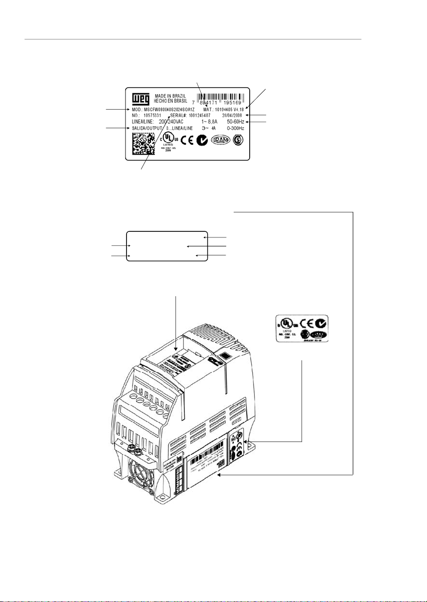
24
CHAPTER 2 - GENERAL INFORMATION
Figure 2.4
- Description and location of the nameplates on the CFW-08
2.4
CFW-08IDENTIFICATION
SoftwareVersion
ManufacturingDate
WEG Part Number
SerialNumber
CFW-08Model
(IntelligentCode)
RatedOutput Data
(Voltage, Frequency)
Lateral Label of the CFW-08
Frontal Nameplate of the CFW-08 (under the keypad)
Note:
toremove the
keypad,refer to the
instructions
inthe item 8.1.1
(figure8.2).
WEG Part Number
SerialNumber
CFW-08Model (IntelligentCode)
SoftwareVersion
ManufacturingDate
CertificationStiker
MSCFW080100T3848SOA1Z
10194356 V 4.18
1001208557 18/04/2008
RatedInputData
(Voltage,Current, etc)

25
CHAPTER 2 - GENERAL INFORMATION
CFW-08
0040
B
2024
E
O
_ _
_ _
_ _
_ _
_ _
_ _
Z
Rated Output
Current for:
220 to 240 V:
0016 = 1.6 A
0026 = 2.6 A
0040 = 4.0 A
0070 = 7.0 A
0073 = 7.3 A
0100 = 10 A
0160 = 16 A
0220 = 22 A
0280 = 28 A
0330 = 33 A
380 to 480 V:
0010 = 1.0 A
0016 = 1.6 A
0026 = 2.6 A
0027 = 2.7 A
0040 = 4.0 A
0043 = 4.3 A
0065 = 6.5 A
0100 = 10 A
0130 = 13 A
0160 = 16 A
0240 = 24 A
0300 = 30 A
Number of
phases of
the power
supply
:
S = single
phase
T = three
phase
B = single
phase or
three phase
Manual
Language:
P=
Portuguese
E= English
S = Spanish
Power
Supply
:
2024 =
200to 240 V
3848 =
380 to 480 V
5060
(**)
=
500-600 V
Options:
S = standard
O = with
options
Degree of
Protection:
Blank
=
s
tandard
N1= Nema 1
N4= Nema
4X
(**)
Human
Machine
Interface:
Blank=
s
tandard
SI = without
interface
(with dummy
panel)
WEG Series 08
Frequency
Inverter
Control Board:
Blank=
standard
control
A
1
=
c
ontrol 1
(Plus Version)
A2
=
c
ontrol
2
(Plus Version
with Als +/-
10 V)
A3 = control 3
(Plus version
with CANopen
protocol)
(*)
A4 = control 4
(Plus version
with
DeviceNet
protocol)
(*)
A5 = control
5
(**)
(for
Multipump
application)
Special
Software:
Blank=
s
tandard
EndCode
RFIFilter:
Blank=
s
tandard
FA=
Category
C2
RFI
filter
(internal or
footprint)
Special
Hardware:
Blank=
s
tandard
HOW TO SPECIFY THE CFW-08MODEL:
NOTES!
Theoption field (S or O)defines if theCFW-08 is a standard version or if it will be equippedwith anyoptional devices.Ifthe
standardversion is required, the specificationcodeendshere.
ThemodelnumberhasalwaystheletterZ at the end. For example:
CFW080040S2024ESZ=standard4.0ACFW-08inverter,single-phase at (200 to 240) V input,withmanual in English.
IftheCFW-08 is equipped with anyoptionaldevices, you must fill out all fields in the correct sequence up tothelastoptional
device,the model numberiscompletedwiththe letter Z.
Thus,for instance if the product above isrequired withNema 1 degree of protection:
CFW080040S2024EON1Z=
standardC
FW-08inverter,4.0A,single-phase,200-240V input,withmanualin Englishlanguage
and with kit for Nema1 degree of protection.
(*)
-
The versionsA3 and A4 of the control board shall be used only with the KFB-CO-CFW08 and with the KFB-DN-CFW08, respectively (refer to item 8.14 and 8.15). The parallel keypad, the
serial remote keypad, the parallel remote keypad, and the serial protocol (Modbus and WEG) cannot be used with these versions of the control board.
(**) -
For these models, contact WEG.

26
CHAPTER 2 - GENERAL INFORMATION
Fortheeffectofthiscode,thestandardproduct is conceived
asfollows:
-CFW-08 with standard control board.
-
Degree of protection:
N
ema
1 for the models 22 A,
28 A and 33 A/ 200-400 V and also 13 A,16 A, 24 A
and 30 A/380-480 V, IP20 for the other models.
CFW-08 Plus - A1 is composed of the inverter and the
controlboard1. Example: CFW080040S2024PO
A1
Z.
CFW-08 Plus - A2 is composed of the inverter and the
control board 2. Example: CFW080040S2024PO
A2
Z.
Thesemodelsarefactorysetforbipolaranaloginputs(-10V
to +10 V).
Thisconfigurationislostwhenthefactorydefaultparameters
areloaded (P204 = 5). Refer to the detailed descriptionof
parametersP204 andP235forfurtherinformation.
CFW-08 Plus - A3 is composed of the inverter, the KFB-
CO-CFW08kitandtheCANopencommunicationprotocol.
Example:CFW-080040S2024PO
A3
Z.
CFW-08 Plus - A4 is composed of the inverter, the KFB-
DN-CFW08kitandtheDeviceNetcommunicationprotocol.
Example:CFW080040S2024PO
A4
Z.
CFW-08 Multipump -A5 is composed of the inverter and
thecontrolboard5,usedformultipumpsystemapplications.
7.0A, 16.0 A, 22 A, 28 A and 33 A /200-240 V and for all
380-480 V models are just available with three-phase
powersupply.
A Category C2 RFI filter (optional)can be installedinside
the inverter in models 7.3 A and 10 A/200-240 V (single-
phase) and 2.7A, 4.3 A, 6.5 A, 10 A, 13 A, 16A, 24 A and
30A/380-480 V.Models 1.6A, 2.6A and 4.0A/200-240 V
(single-phase)and 1.0A, 1.6A, 2.6Aand4.0A/380-480V
can be providedmounted on a footprint CategoryC2 RFI
filter(optional).
Thelistingoftheexistingmodels(voltage/current)isshown
initem 9.1.

27
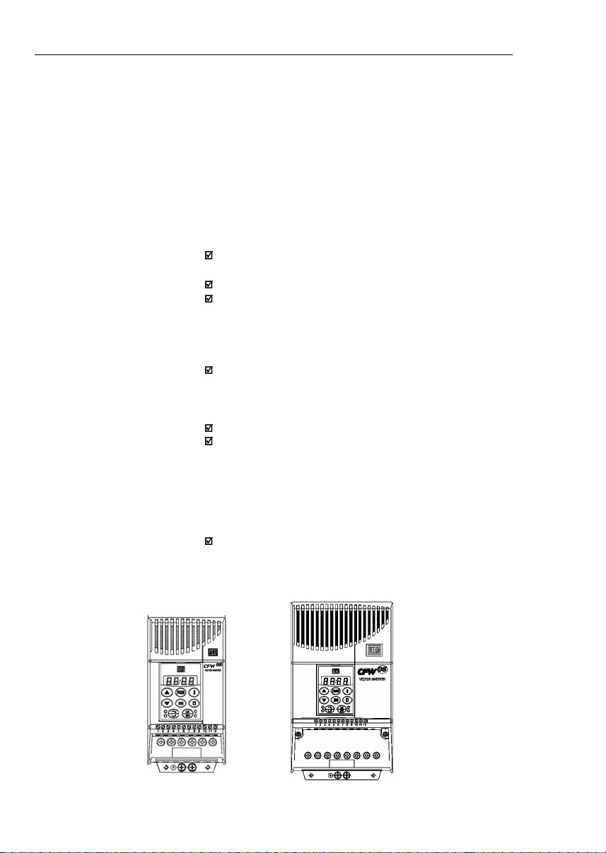
CHAPTER 2 - GENERAL INFORMATION
The CFW-08is supplied in cardboard boxes.
Theoutsideofthepackingboxhasa nameplatethatisidentical
tothat on the CFW-08.
Please check if the CFW-08is the one you ordered.
Checkifthe:
CFW-08nameplatedatamatcheswithyourpurchaseorder.
Theequipmenthas not been damaged duringtransport.
Ifanyproblem isdetected,contactthe carrier immediately.
If the CFW-08 is not installed immediately,store it in a clean
anddryroom(storage temperatures between -25 °C [-13 °F]
and 60 °C [140 ºF]). Cover it to protect against dust, dirt or
othercontamination.
ATTENTION!
When theinverterisstoredfor alongtime,it is recommended
to power the inverter up for 1 hour every year. Make sure to
use a power supply with the following characteristics for all
models (200-240 V or 380-480 V): 220 V, single-phase or
three-phase,50 Hz or 60 Hz, withoutconnectingthemotorto
thedriveoutput.Afterpoweringupthe drive,keepitoff for 24
hoursbeforeusingitagain.
2.5
RECEIVING
AND
STORING
28
CHAPTER3
INSTALLATION ANDCONNECTION
Thischapterdescribestheproceduresforthe electricaland
mechanicalinstallationoftheCFW-08.Theseguidelines
andsuggestionsmust be followed for proper CFW-08
operation.
The location of the inverterinstallation is an important factor
to assure good performance and long useful life for its
components. For proper installation, we make the following
recommendations:
Avoid direct exposure to sunlight, rain, high moisture and
sea air;
Avoidexposuretoexplosiveorcorrosivegasesandliquids;
Avoid exposure to excessive vibration, dust, oil or any
conductiveparticles in the air.
Environment conditions:
Temperature: 0 ºC to 40 ºC (32 ºF to 104 ºF ) - nominal
conditions.From40ºCto50 ºC (32ºF to122ºF)-with2%
currentderatingfor each 1 ºC (1.8 ºF) degreeabove40 ºC
(104ºF).
Relativeairhumidity:5 % to 90 %-non-condensing.
Maximumaltitude: 1000m (3,300ft) -nominalconditions.
From 1000 m to 4000 m (3,300 to 13123.3 ft) - with 1 %
currentreduction for each 100 m (328 ft) above 1000 m
(3,300ft).
From2000m (6561.6ft) to 4000 m (13123.3ft)- avoltage
reduction of 1.1 % every 100 m (328 ft) above 2000 m
(6561.6ft).
Pollution degree: 2 (according to EN50178 and UL508C)
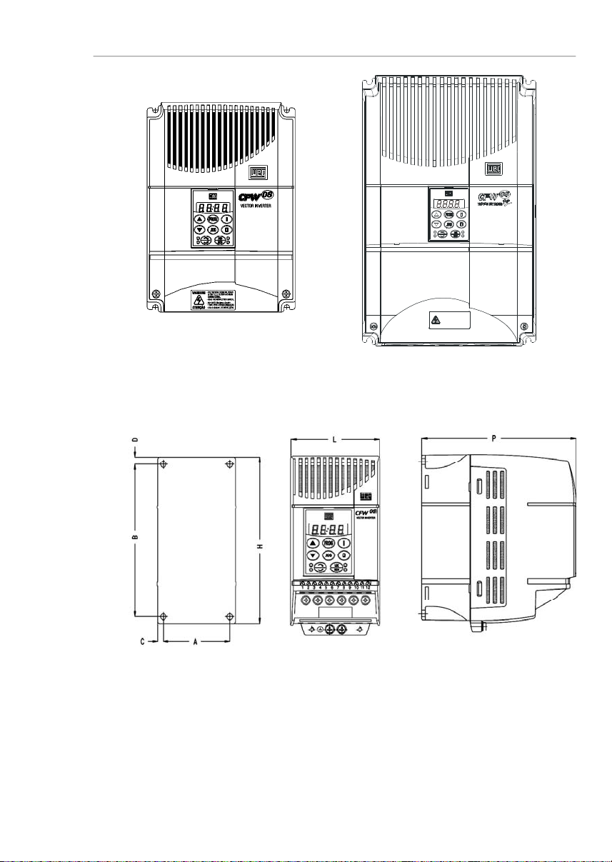
The figure 3.1 and the table 3.1, provides external mounting
specifications,and externalfixingholesof theCFW-08.
3.1
MECHANICAL
INSTALLATION
3.1.1
Environment
3.1.2
CFW-08Mounting
Specifications
Figure 3.1
- CFW-08 mounting specifications
29
CHAPTER 3 - INSTALLATION
AND CONNECTION
Figure 3.1 (cont.)
- CFW-08 mounting specifications
VIEW OF THE
MOUNTINGBASE
FRONTAL
VIEW
LATERALVIEW
1MIN.A PÓSADESENERGIZAÇÃO.
-SOMENTE REMOVAATAMPA
-LEIA OMANUALDE INSTRUÇÕES.
ATENÇÃO
-READ THEINSTRUCTIONSMA NUAL.
AFTER1 MIN.POWERHA SBEEN
-ONLYREMOVE TERMINALCOVER
WARNING
DISCONNECTED.
Loading...