

Page 1
Page 2
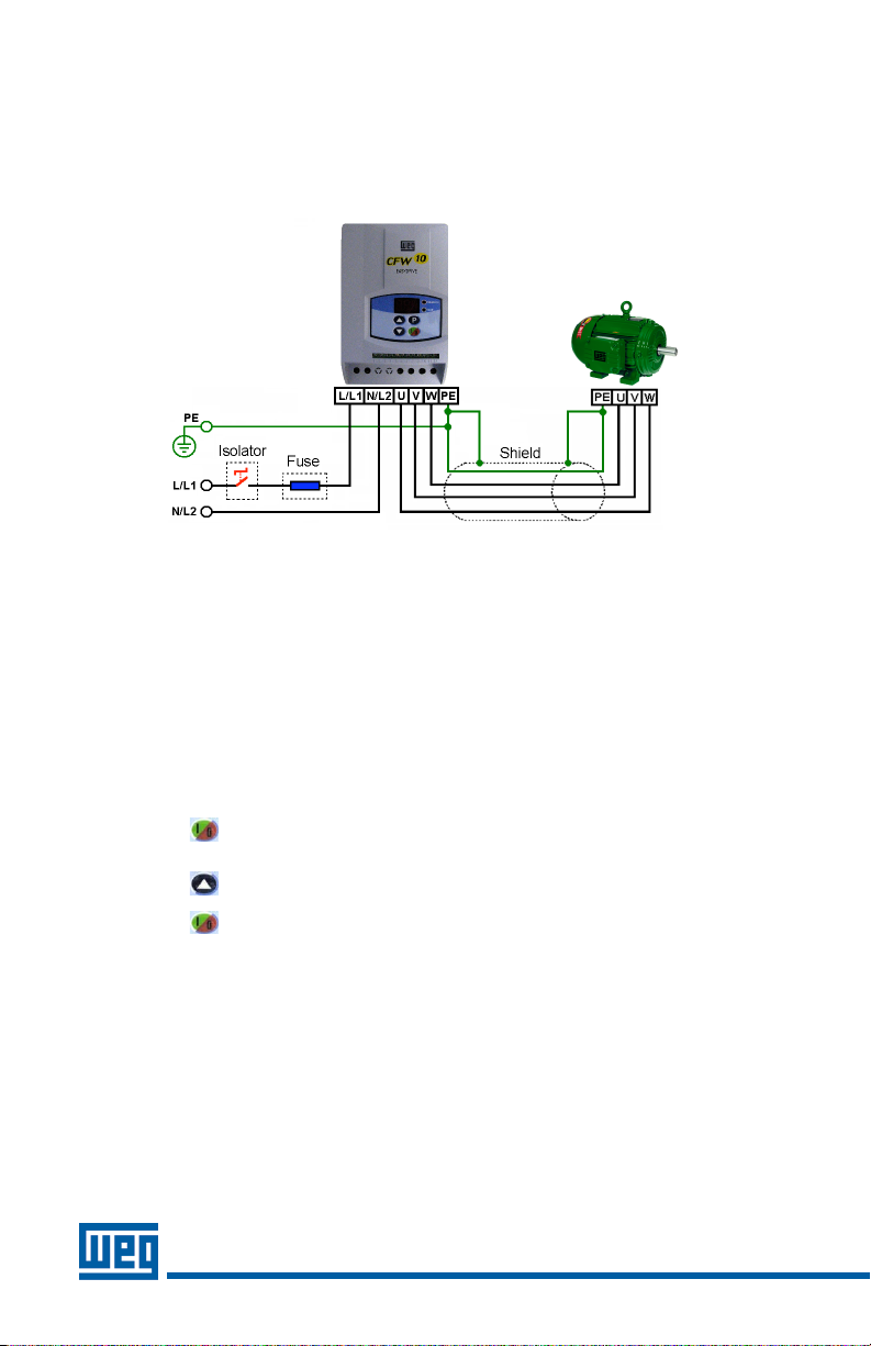
Power Connections:
The CFW10 Quick Start Guide is a supplement to h elp get the CFW10 started quickly using the mos t common installa tion
and co nfiguration options. This C FW10 Qu ic k Start Guide is not mean t to replace the CFW10 User’s Manual. For de tailed
instructions, safety precautions, proper mounting, installation, configura tion, and operation please refer to the CFW10
User’s Guide. W arning: O nly quali fied person nel shoul d plan or implement the ins tallation, s tart-up, o peration and
maintenance of this equ ipment. P ersonnel m ust read the entire CFW10 User’s Guide before a ttempting to inst all, operate
or trou bleshoot the CFW1 0.
Figure 1 - Power and Grounding Connections
Basic Wiring:
1. Mount the CF W10 to a flat v ertical sur face.
2. Connect the i ncoming s ingle phase power leads to the L/L1 and N/L2 connections on the power terminal and
connect the GR OUND lead to PE on the pow er termina l (Refer to Figure 1).
3. Connect the motor leads to the U, V, and W connections on the p ower termi nal and connect the GROUND lead to
PE on the power terminal (Refer to F igure 1). Note: Only three-phase AC motors can be used .
4. Apply power t o the CFW10 drive. The d rive will run self diagnostics and if no proble ms are found it wi ll display
“rdY”. Note: Ne w CFW10 drives are shipped with parameters preset to fac tory defau lts. If you need to reload
factory defaults at any time, first set password parameter P000=5 then set fa ctory defau lt parame ter P204=5 .
Keypad Start/Stop (Local Mode): This o peration mode is recommend ed for users who are operating the driv e for
the firs t time without additional control connections .
1. Press the start key. Th e motor will accelerate from 0.0 to 3.00 Hz (minimum speed P133), in the clock wise
direction. Note: If the direction of rotation is no t correc t, switch off the dr ive and wait until the ca pacitors d ischarge
completely (as l ong as 10 minutes) and then s wap any two wires at the mot or output.
2. Press the key and hold it to increase motor s peed (ma ximum spe ed P134). Note: On Plus versions use the
keypad potentiometer located on the bot tom righ t of the k eypad to adjust speed.
3. Press the stop ke y . The motor decelerates to 0.0Hz and stops wi th a display of “rdY”.
2
Page 3

Keypad Operation and Parameter Setup:
Figure 2 – Keypad Operation
Display
Display Description
rdY
Drive is ready to be enabled.
Sub
Power supply voltage to o low for drive o peration.
dcb
Drive in DC braking mode.
EPP
Drive is loadin g factory setting.
Note: Plus ver sions of the CFW10 have a
speed potentiometer on the lower right
side o f the keypad which is u sed to
increase/decrease speed.
Key
Description
Switches the dis play betwe en
parameter number and
content.
Increases Speed (frequency)
and Parameter
number/content
Decreases Speed and
Parameter number/conten t
Starts/Stops the drive v ia the
acceleration/deceler ation
ramp and res e ts the drive
after a fault.
The C FW10 doe s not require parameter programming prior to start u p and is ready to opera te with the factory default
settings. A para meter ex a mple is given below to familiarize the use r with parameter navigat ion, viewing , and
programming.
Action
LED D isplay
Description
After power is applied to the drive, the display shows
the fol lowing mes sage.
Drive is ready to be started.
Press the key to view parameter number. The red
LED on the keypad will light to indic ate “para meter
number”.
Press the or arrow keys to se le ct a
parameter.
Select the desire d parame ter. This
example uses parameter number
P100 (Acceleration Time).
Press the key to view the value of the parameter.
The green LE D on the keypad will ligh t to indicate
“parameter value”.
This is the numerical value
associated with the para meter. F o r
this e xample the n P100=5 .0
therefore the ac celeration time is set
for 5 seconds .
Press the or arrow keys to ch a nge the
parameter value.
Set the new desired value. In this
example the a cceleration time has
been increased to 6.1 seconds.
Note: To cha nge para meter values
you m ust first set the access
parameter P000=5. Some parameter
changes require the driv e be
stopped first.
Press the key to store the new value.
The new value for P100
(acceleration time) is stor ed in
memory.
Repeat this pr ocedure for other parameters that may
need to be changed.
LED Disp lay –
indicates f ault
codes, inver ter
status, para meter
number and value.
Green L ED –
When li t the
display ind icates
the param eter
value.
Red LED –
When li t the
display ind icates
the param eter
number.
3
Page 4

Keypad Start/Stop (Local Mode) continued:
4. If para meters were access ed or changed under Parameter Setup then the las t parameter number or value will be
displayed. Scroll up or down with the or keys to the re ad only parameter P002 (Frequency
Proportional Value for Sp eed) and press the key to see the value.
5. Return to step 1 and press the s tart key to start the driv e.
Local/Remote Modes:
In the previous section the drive was operated from the keypad
(Local Mode). If you wish to o perate in remote mode you will n eed to
add an external Local/Re mote sw itch. Note: To control speed in
remote mode a speed potentio meter (figure 5) can be a dded or the
up and down arrow keys on the key pad can be used by set ting
P222=0. Plus versions ca n use the keypad speed potentiometer by
setting P222=3.
Parameters: Confirm DI3 is set to Local/Remote (P265=6) .
Control Wiring: Local/Remote switch is N .O (normally open) and is
connected as sh own in Figure 3.
2 Wire Start/Stop (Remote Mode):
Parameters:
1. Confirm DI4 is set to START/STOP (P266=4).
2. Set P229 =1 (DIx) if you want the 2 wire control in loca l mode.
3. Confirm P230=1 (DIx) if you want the 2 wire control in remote
mode.
Control Wiring: Verify t here is a jumper between XC1-1 (general
enable) and X C1-5 or the drive will no t work. Jumper can be
eliminated if D I1 is set to “No Function” (P263=0) . Start/Stop switch is
N.O. (no rmally op en) and is connected as s hown in Figure 3.
Figure 3 –
Local/Remote and 2 Wir e Start/S top
4
Page 5

3 Wire Start/Stop (Remote Mode):
Parameters:
1. Set D I1 (Start) to “On” (P263=13). See note b elow.
2. Set D I2 (Stop) to “Off” (P264=14).
3. Set D I4 to “No function” (P266=0).
4. Set P229=1 (D Ix) if you want the 3 wire control in
local mode.
5. Confirm P230=1 (DIx) if you want the 3 wire contro l
in re mote mode .
Control Wiring: “Start” and “ Stop” are momentary push
button s witches and are connec ted as shown in F igure 4.
“Start” is a N.O. (normally open) contact and “Stop” is a N.C.
(normally closed) contact.
Note: When initially se tting DI1 to START (P263=13) an E24
(programming) error will occur u ntil DI2 is set to STOP
(P264=14).
Figure 4 - 3 Wire Start/Stop
Operation from Remote Analog Input (Speed Pot):
Parameters:
1. Confirm P222=1 (Remote Speed Ref=AI1)
Control Wiring: Speed Pot value must be ≥ 5 KΩ bu t ≤ 10KΩ a t
2W an d is connected as shown in Figu re 5.
Figure 5 – Analog Input with Speed Pot
Fault Codes:
When a fault is detected, the drive is disabled and the Fault Code is display ed. (Exa mple E01). To restart the drive a fter a
fault h as occurred , the drive must be r eset. Rese t ting the drive can be done by disconnectin g and reapplying AC power
(power-on reset), by p ressing the “O/RES ET” key (manual reset), automatic reset, or v ia digi tal inputs. For details on
Reset and a full list and des cription of Fault Codes please read Chapter 7 in the CFW10 User’s Guide.
5
Page 6

Parameters Example:
• The follow ing is a typica l list of parame ter changes that may be needed in addition to the factory default settings
(P204=5).
P000=5 Parameter Access (5 = Password)
P204=5 Loads Factory Defaul t
P100=5 Acceleration Time = 5 seconds
P101=10 Deceleration Time = 10 s econds
P133=3.00 Minimum Frequency = 3.00 Hz
P134=60.00 Maximum Frequency – 60.00 Hz
• Local/Remote parameters allow the drive to be set up to operate from Key pad, Remote Terminal, or a
programmed combination of keyp ad and terminal i nputs.
P221 – Local Speed R e ference Selec tion
P222 – Remote Speed Reference Selection
P229 – Local Command Selection
P230 – Remote Command Selection
P231 – Forward/Rever se Selection
• Read On ly Parameters (P002 – P040) can be use d for monitoring an d troubleshoo ting. For a full list and
description please re ad the CFW10 U ser’s Guide. By monitoring cer tain read only p a rameters, driv e operational
values can be determined without the use of any other test equi pment.
P002 – Frequency Proportional Value (Speed)
P003 – Motor Current
P004 – used to moni tor DC Link Voltage .
P005 – Motor Frequency
P007 – Motor Output Voltage
P014 – Last fault
These ar e just a few examples of d rive set-up and parameters. Please re ad the CFW10 U ser’s Guide for additional
information.
6
Publication Numer QS005CFW10
 Loading...