

Page 1
Frequency Inverter
Convertidor de Frecuencia
Inversor de Freqüência
Frequenzumrichter
Variateur de Vitesse
Преодразователь частоты
Frequentie Regelaar
Frekvensomvandlare
CFW-08
User's Guide
Manual del Usuario
Manual do Usuário
Bedienungsanleitung
Manuel d'utilisation
Руководство пользователя
Gebruikers Handleiding
Användarinstruktioner
Motors | Energy | Automation | Coatings
Page 2

03/2009
FREQUENCY
INVERTER
MANUAL
ATTENTION!
It is very important to check if the
inverter software version is the
same as indicated above.
Series:
CFW-08
Software:
vers
ion5.2
X
Language
:
English
Document
:
0899.5242 / 09
Page 3

2
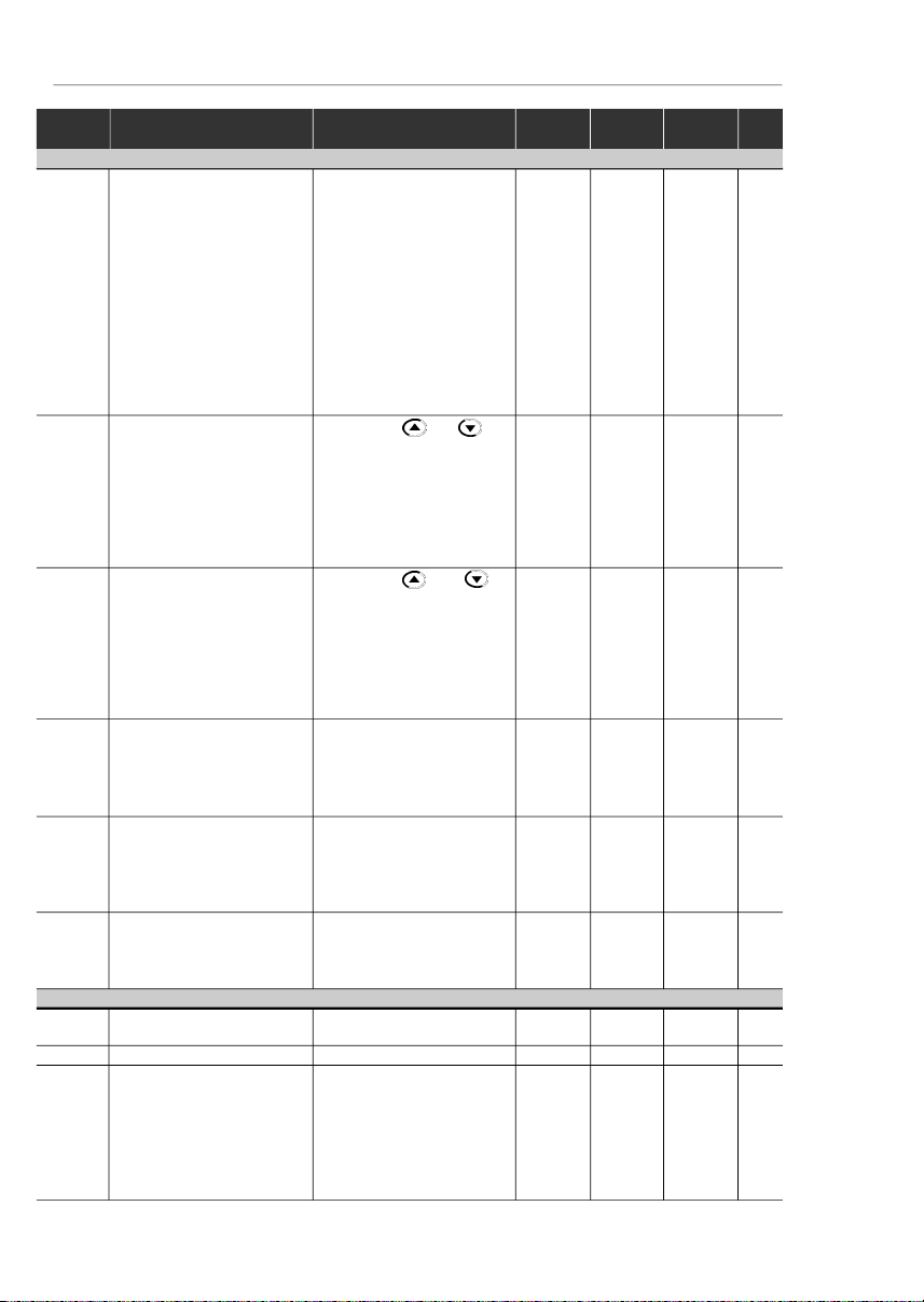
Summary of Revisions
Thetablebelowdescribesallrevisionsmade tothismanual.
Revision
Description
Section
1
First Edition
-2Inclusionof the item 3.3 - European
Refer to item 3.3
EMCDirective -Requirements for
ConformingInstallations
3
GeneralRevision
-4External Parallel Keypadand
Refer to item 8.3
Fix Kit included and
and8.18
GeneralRevision
5
Descriptionchanged of the
Refer to item 8.5
ParallelCable
for the External Parallel Keypad
Item7.5 (SparePart List) removed
ParameterP536 included
Refer to item 6.3.5
andGeneralRevision
6
GeneralRevision
-7Inclusionof new models (22 A, 28 Aand
Refer to item 9.1
33A/200-240 V; 24A and 30 A/380-480V)
Addition of new I/O functions
Refer to item 3.2.5
on the control board
Modificationof circuit breakers table
Refer to item 3.2.3
Modificationof chapter 3
(installationand connections)
Modificationofparameters
Refer to item 4.2.4
incompatibility table
Additionof parameters P253,
Refer to item 6.3
P267and P268
Addition of new functions at parameters
P235, P239, P295and P404
Modificationof factorydefault
Refer to item 6.3.3
valueofparameterP248
Addition of error code E32
Refer to item 7.1
8
GeneralRevision
Inclusion of items into the table of
Refer to item 4.2.4
parametersincompatibility
Changeon the WEG part number
Referto chapter 8
ofthe optional devices
Inclusionof the table containing the
Refer to item 3.1.3.1
airflowrequirementsforpanel mounting
Inclusionof the following optionals:
Referto chapter 8
KRS-485-CFW08,KFB-CO-CFW08,
KFB-DN-CFW08and KAC-120-CFW08
Inclusionof the new versions
Refer to item 2.4
of the control board:A3 and A4
9
TheSleep function wasadded
Referto chapter 6
(parametersP212, P213and P535)
TheAnalogInputDead Zonefunction
wasadded (P233)
TheKDC-24VR-CFW08and
Refer to items 8.9
KDC-24V-CFW08optionmodules
and8.10
wereadded
NewEMC filters wereadded
Refer to item 3.3.4
Noteson the CFW-08 Nema 4X
Referto chapter 2.4
and the 575 V lines were added
Modificationof the gainequation
for the analog inputs
Generalrevision
-
Page 4

Summary
QuickParameterReference,
Fault and Status Messages
I Parameters
....................................................................
8
II FaultMessages
...........................................................
16
IIIOtherMessages
...........................................................
16
CHAPTER 1
Safety Notices
1.1SafetyNotices in the Manual
.....................................
17
1.2SafetyNotices on theProduct
...................................
17
1.3PreliminaryRecommendations
.................................
17
CHAPTER 2
General Information
2.1AboutthisManual
......................................................
19
2.2Software Version
.......................................................
19
2.3About the CFW-08
....................................................
20
2.4CFW-08Identification
...............................................
24
2.5ReceivingandStoring
...............................................
27
CHAPTER 3
Installation and Connection
3.1MechanicalInstallation
..............................................
28
3.1.1Environment
........................................................
28
3.1.2Mounting Specifications
......................................
28
3.1.3
Positioningand Fixing
........................................
31
3.1.3.1PanelMounting
..........................................
32
3.1.3.2SurfaceMounting
.......................................
33
3.2
ElectricalInstallation
.................................................
33
3.2.1Power/GroundingTerminals
..............................
33
3.2.2
Locationof the PowerTerminals,Grounding
TerminalsandControlTerminalConnections
......353.2.3
Power/GroundingWiringand CircuitBreakers
..363.2.4Power Connections
............................................
37
3.2.4.1
ACInput Connection
................................
39
3.2.4.2
OutputConnections
..................................
40
3.2.4.3
GroundingConnections
............................
40
3.2.5
Signaland Control
Connections
.........................
42
3.2.5.1
DigitalInputsas LowLevelActive
(S1:1 to OFF)
...........................................
46
3.2.5.2
DigitalInput as High LevelActive
(S1:1to ON)
.............................................
47
3.2.6TypicalTerminalConnections
.............................
48
3.3
EuropeanEMCDirective-Requirements
forConformingInstallations
......................................
51
3.3.1Installation
...........................................................
51
Page 5

Summary
3.3.2Emission and Immunity LevelsDescription
........
52
3.3.3InverterModels and Filters
..................................
54
3.3.4 EMC FiltersCharacteristics
...............................
57
CHAPTER 4
Keypad (HMI) Operation
4.1Keypad(HMI)Description
.........................................
67
4.2Useof the Keypad(HMI)
...........................................
68
4.2.1KeypadOperation
..............................................
69
4.2.2InverterStatus
.....................................................
70
4.2.3Read-OnlyParameters
.......................................
71
4.2.4Parameter Viewing and Programming
...............
71
CHAPTER 5
Start-up
5.1 Pre-Power Checks
....................................................
74
5.2Initial Power-up
..........................................................
74
5.3Start-up
......................................................................
75
5.3.1
Start-upOperationvia Keypad(HMI)-
Type of Control:LinearV/F (P202 = 0)
...............
76
5.3.2
Start-upOperation viaTerminals-
Control Mode: Linear V/F (P202 = 0)
.................
77
5.3.3
Start-upOperation via Keypad -
Control Mode: Vector(P202 = 2)
........................
78
CHAPTER 6
DetailedParameter Description
6.1Symbols...
.................................................................
83
6.2Introduction
................................................................
83
6.2.1Control Modes (V/F and Vector)
.........................
83
6.2.2V/F Control
.........................................................
83
6.2.3VectorControl (VVC)
..........................................
84
6.2.4FrequencyReferenceSources
...........................
85
6.2.5
Commands
.........................................................
88
6.2.6Local/RemoteOperationModes
........................
88
6.3Parameter Listing
......................................................
89
6.3.1
AccessandRead-onlyParameters-
P000 to P099
.....................................................
90
6.3.2Regulation Parameters- P100 to P199
.............
92
6.3.3 Configuration Parameters- P200 to P398
.......
102
6.3.4 Motor Parameters - P399 to P499
...................
128
6.3.5 Special Function Parameters - P500 to P599
..
131
6.3.5.1Introduction
..............................................
131
6.3.5.2Description
..............................................
131
6.3.5.3PID Start-upGuide
...................................
134
Page 6

Summary
CHAPTER 7
Diagnosticsand Troubleshooting
7.1Faults and PossibleCauses
...................................
141
7.2Troubleshooting
.......................................................
144
7.3ContactingWEG
.....................................................
145
7.4PreventiveMaintenance
..........................................
145
7.4.1CleaningInstructions
.........................................
146
CHAPTER 8
CFW-08Options andAccessories
8.1HMI-CFW08-P
........................................................
149
8.1.1InstructionsforInsertionand Removingof
theHMI-CFW08-P
............................................
149
8.2TCL-CFW08
...........................................................
149
8.3HMI-CFW08-RP
......................................................
150
8.3.1HMI-CFW08-RPInstallation
..............................
150
8.4MIP-CFW08-RP
......................................................
151
8.5 CAB-RP-1, CAB-RP-2, CAB-RP-3, CAB-RP-5,
CAB-RP-7.5, CAB-RP-10
......................................
151
8.6HMI-CFW08-RS
......................................................
151
8.6.1HMI-CFW08-RSInstallation
..............................
152
8.6.2HMI-CFW08-RSStart-up
..................................
152
8.6.3KeypadCopyFunction
.....................................
153
8.7MIS-CFW08-RS
......................................................
153
8.8 CAB-RS-1, CAB-RS-2, CAB-RS-3, CAB-RS-5,
CAB-RS-7.5, CAB-RS-10
......................................
153
8.9 KDC-24VR-CFW08
................................................
154
8.10 KDC-24V-CFW08
.................................................
155
8.11KCS-CFW08
.........................................................
156
8.11.1
InstructionsforKCS-CFW08
InsertionandRemoval
.....................................
157
8.12 KSD-CFW08
........................................................
157
8.13KRS-485-CFW08
.................................................
158
8.14 KFB-CO-CFW08
..................................................
159
8.15 KFB-DN-CFW08
..................................................
160
8.16 KAC-120-CFW08, KAC-120-CFW08-N1M1
KAC-120-CFW08-N1M2
......................................
162
8.17 KMD-CFW08-M1
..................................................
163
8.18KFIX-CFW08-M1, KFIX-CFW08-M2
....................
164
8.19KN1-CFW08-M1, KN1-CFW08-M2
......................
165
8.20RFI Filter
...............................................................
166
8.21Line Reactor
..........................................................
167
8.21.1Application Criteria
.......................................
167
8.22 Load Reactor
........................................................
170
8.23Dynamic Braking
...................................................
171
8.23.1ResistorSizing
..............................................
171
8.23.2Installation
.....................................................
172
8.24SerialCommunication
...........................................
173
Page 7

Summary
8.24.1Introduction
....................................................
173
8.24.2RS-485andRS-232InterfacesDescription
.
174
8.24.2.1RS-485
..............................................
175
8.24.2.2RS-232
..............................................
176
8.24.3Definitions
.....................................................
176
8.24.3.1Used Terms
.......................................
176
8.24.3.2Parameter/Variables Resolution
........
177
8.24.3.3Character Format
..............................
177
8.24.3.4Protocol
.............................................
177
8.24.3.5Execution and MessageTest
.............
180
8.24.3.6MessageSequence
..........................
180
8.24.3.7 Variable Code
...................................
180
8.24.4Message Examples
......................................
181
8.24.5 Variablesand Errors of the Serial
Communication
............................................
181
8.24.5.1 Basic Variables
.................................
181
8.24.5.2 Message Examples with Basic
Variables
............................................
184
8.24.5.3ParametersRelatedtotheSerial
Communication
...................................
185
8.24.5.4ErrorsRelated to the Serial
Communication
.................................
186
8.24.6TimeforRead/Write of Messages
................
186
8.24.7Physical Connection RS-232andRS-485
....
187
8.25Modbus-RTU
.........................................................
188
8.25.1IntroductiontoModbus-RTUProtocol
...........
188
8.25.1.1Transmission Modes
.........................
188
8.25.1.2Message StructureinRTU Mode
......
188
8.25.2Operation oftheCFW-08inthe
Modbus-RTUNetwork
..................................
191
8.25.2.1RS-232 and RS-485 Interface
Description
.......................................
191
8.25.2.2 InverterConfigurationinthe
Modbus-RTU Network
.....................
191
8.25.2.3AccesstotheInverterData
...............
192
8.25.3Detailed Function Description
......................
195
8.25.3.1Function 01 - Read Coils
..................
195
8.25.3.2Function 03-Read Holding Register
196
8.25.3.3Function 05 - WriteSingle Coil
.........
197
8.25.3.4Function 06-Write SingleRegister
..
198
8.25.3.5Function 15 -Write Multiple Coils
......
198
8.25.3.6Function 16 - WriteMultipleRegisters
199
8.25.3.7Function 43 - Read Device
Identification
.....................................
200
8.25.4Modbus-RTUCommunicationErrors
............
202
8.25.4.1 Error Messages
...............................
203
Page 8

Summary
CHAPTER 9
TechnicalSpecifications
9.1
Power Data
..............................................................
204
9.1.1 200-240 V Power Supply
..................................
204
9.1.2 380-480 V Power Supply
..................................
205
9.2Electronics/GeneralData
........................................
208
9.3WEG Standard IV-PoleMotorData
.........................
2098CFW-08 - QUICK PARAMETER REFERENCE
Page 9

Software: V5.2X
Application:
Model:
SerialNumber:
Responsible:
Date: / / .
I.Parameters
QUICK PARAMETER REFERENCE, FAULT AND STATUS MESSAGES
Parameter
Function
Adjustable Range
Factory
Unit
User
Page
Setting
Setting
P000
ParameterAccess
0 to 4 = Read
0-90
5 = Alteration
6 to 999 = Read
READONL
YPARAMETERS-
P002to P099
P002
FrequencyProportionalValue
0 to 6553
--90
(P208xP005)
P003
MotorOutput Current
0 to 1.5xI
nom
-A90
P004
DCLink Voltage
0 to 862
-V90
P005
Motor Output Frequency
0.00 to 300.0
-Hz90
P007
MotorOutput Voltage
0 to 600
-V90
P008
HeatsinkTemperature
25 to 110
-°C91
P009
(1)
MotorTorque
0.0 to 150.0
-%91
P014
Last Fault
00 to 41
--91
P023
SoftwareVersion
x . y z--
91
P040
PID Process Variable
0 to 6553
--91
(Value% x P528)
REGULA
TIONPARAMETERS -
P100 to P199
Ramps
P100
AccelerationTime
0.1 to 999
5.0s92
P101
DecelerationTime
0.1 to 999
10.0s92
P102
Ramp 2 AccelerationTime
0.1 to 999
5.0s92
P103
Ramp2 DecelerationTime
0.1 to 999
10.0s92
P104
S Ramp
0= Inactive
0-92
1 = 50 %
2 = 100 %
Frequency Reference
P120
DigitalReferenceBackup
0= Inactive
1-93
1 = Active
2 = Backup by P121
P121
KeypadReference
P133 to P134
3.00Hz93
P122
JOGSpeedReference
0.00 to P134
5.00Hz94
P124
MultispeedReference1
P133 to P134
3.00Hz94
P125
MultispeedReference2
P133 to P134
10.00Hz94
P126
MultispeedReference3
P133 to P134
20.00Hz94
P127
MultispeedReference4
P133 to P134
30.00Hz95
P128
MultispeedReference5
P133 to P134
40.00Hz95
P129
MultispeedReference6
P133 to P134
50.00Hz95
P130
MultispeedReference7
P133 to P134
60.00Hz95
P131
MultispeedReference8
P133 to P134
66.00Hz95
Page 10

9
CFW-08 - QUICK PARAMETER REFERENCE
Parameter
Function
Adjustable Range
Factory
Unit
User
Page
Setting
Setting
(*)
The factory default of parameter P136 depends on the inverter model as follows:
- models 1.6-2.6-4.0-7.0 A/200-240 V and 1.0-1.6-2.6-4.0 A/380-480 V: P136 = 5.0 %;
- models 7.3-10-16 A/200-240 V and 2.7-4.3-6.5-10 A/380-480 V: P136 = 2.0 %;
- models 22-28-33 A/200-240 V and 13-16-24-30 A/380-480 V: P136 = 1.0 %.
Speed Limits
P133
Minimum Frequency(F
min
)
0.00 to P134
3.00Hz95
P134
MaximumFrequency (F
max
)
P133 to 300.0
66.00Hz96
V/F Control
P136
(2) (*)
ManualTorque Boost
0.0 to 30.0
5.0 or%96
(IxRCompensation)
2.0 or
1.0
(*)
P137
(2)
AutomaticTorqueBoost
0.00 to 1.00
0.00-97
(AutomaticIxR Compensation)
P138
(2)
SlipCompensation
0.0 to 10.0
0.0%97
P142
(2) (3)
Maximum Output Voltage
0 to 100
100%98
P145
(2) (3)
FieldWeakening
P133 to P134
50.00 Hz or
Hz98Frequency(F
nom
)
60.00 Hz
depending
on the
market
DC Link Voltage Regulation
P151
DCLink VoltageRegulation
200 V models: 325 to 410
380V99
Level
400 V models: 564 to 820
780
Overload Current
P156
MotorOverloadCurrent
0.2xI
nom
to 1.3xI
nom
1.2xP401
A
100
Current Limitation
P169
MaximumOutput Current
0.2xI
nom
to 2.0xI
nom
1.5xP295
A
101
Flux Control
P178
(1)
Rated Flux
50.0 to 150
100%101
CONFIGURA
TIONPARAMETERS - P200
to
P398
Generic Parameters
P202
(3)
ControlMode
0 = Linear V/F Control
0-102
(Scalar)
1 = Quadratic V/F Control
(Scalar)
2 = S
ensorlessVectorControl
P203
(3)
SpecialFunction Selection
0 = No function
0-103
1 = PID Regulator
P204
(3)
Load Factory Setting
0 to 4 = No Function
0-104
5 = Loads Factory Default
P205
DisplayDefault Selection
0 = P005
2-104
1 = P003
2 = P002
3 = P007
4, 5 = Not Used
6 = P040
P206
Auto-ResetTime
0 to 255
0s104
P208
ReferenceScale Factor
0.00 to 99.9
1.00-104
P212
Frequencyto Enable the Sleep 0.00 to P134
0.00Hz105
Mode
P213
Time Delayto Activate the
0.1 to 999
2.0s105
SleepMode
P215
(3) (4)
Keypad Copy Function
0 = Not Used
0-106
1 = Copy (inverter
keypad)
2= Paste (keypad
inverter)
P219
(3)
SwitchingFrequency
0.00 to 25.00
6.00Hz107
ReductionPoint
Page 11
10
CFW-08 - QUICK PARAMETER REFERENCE
Parameter
Function
Adjustable Range
Factory
Unit
User
Page
Setting
Setting
(**)
Only available on the control board A2 (refer to item 2.4). For programming instructions, please, refer to the parameter P235 detailed
description.
Local/Remote Definition
P220
(3)
Local/Remote
0 = Always Local
2-108
Selection Source
1 = Always Remote
2 =HMI-CFW08-P or
HMI-CFW08-RPKeypad
(default:local)
3 =HMI-CFW08-P or
HMI-CFW08-RPKeypad
(default:remote)
4 = DI2 to DI4
5=
SerialorHMI-CFW08-RS
Keypad(default: local)
6=
SerialorHMI-CFW08-RS
Keypad(default:remote)
P221
(3)
FrequencyLocalReference
0 = Keypad and
0-109
Selection
1 = AI1
2, 3 = AI2
4 = E.P.
5 = Serial
6 = Multispeed
7 = Add AI
0
8 = Add AI
P222
(3)
FrequencyRemoteReference
0 = Keypad and
1-109
Selection
1 = AI1
2, 3 = AI2
4 = E.P.
5 = Serial
6 = Multispeed
7 = Add AI
0
8 = Add AI
P229
(3)
LocalCommand Selection
0 =HMI-CFW08-P or
0-109
HMI-CFW08-RPKeypad
1 = Terminals
2 = Serial or
HMI-CFW08-RSKeypad
P230
(3)
RemoteCommand Selection
0 =HMI-CFW08-P or
1-109
HMI-CFW08-RPKeypad
1 = Terminals
2 = Serial or
HMI-CFW08-RSKeypad
P231
(3)
Forward/ReverseSelection
0 = Forward
2-110
- Local and Remote
1= Reverse
2 = Commands
3 = DIx
Analog Input (s)
P233
AnalogInputDead Zone
0= Inactive
1-110
1 = Active
P234
AnalogInputAI1 Gain
0.00 to 9.99
1.00-111
P235
(3) (5)
Analog Input AI1 Function
0 = (0 to 10) V/(0 to 20) mA /
0-112
(-10 to +10) V
(**)
1 = (4 to 20) mA
2 = DI5 PNP
3 = DI5 NPN
4= DI5 TTL
5 = PTC
Page 12

11
CFW-08 - QUICK PARAMETER REFERENCE
Parameter
Function
Adjustable Range
Factory
Unit
User
Page
Setting
Setting
P236
AnalogInputAI1 Offset
-999 to +999
0.0%113
P238
(6)
AnalogInputAI2 Gain
0.00 to 9.99
1.00-113
P239
(3)(5)(6)
Analog Input AI2 Function
0 = (0 to 10) V/(0 to 20) mA/
0-113
(-10 to +10) V
(**)
1 = (4 to 20) mA
2 = DI6 PNP
3 = DI6 NPN
4= DI6 TTL
5 = PTC
P240
(6)
AnalogInputAI2 Offset
-999 to +999
0.0%113
P248
Analog Inputs Filter
0 to 200
10ms113
TimeConstant
Analog Output
P251
(6)
AnalogOutput
0 = Output Frequency (Fs)
0-114
AO Function
1 = InputReference (Fe)
2 = Output Current (Is)
3, 5, 8 = Not Used
4 = MotorTorque
6 = Process Variable (PID)
7 =Active Current
9 = PID Setpoint
P252
(6)
Analog Output AO Gain
0.00 to 9.99
1.00-114
P253
Analog OutputAO Signal
0 = (0 to 10) V/(0 to 20) mA
0-114
1 = (4 to 20) mA
Digital Inputs
P263
(3)
Digital Input DI1Function
0 = No Function or General
0-115
Enable
1 to 7 and 10 to 12 =
GeneralEnable
8 = Forward Run
9 = Start/Stop
13 = FWD Run Using
Ramp2
14 = On
P264
(3)
Digital Input DI2Function
0= Forward/Reverse
0-115
1 = Local/Remote
2 to 6 and 9 to 12 = Not
U
sed
7 = Multispeed (MS2)
8= Reverse
13 = REV Run - Ramp 2
14 = Off
P265
(3) (7)
Digital InputDI3 Function
0= Forward/Reverse
10-115
1 = Local/Remote
2 = GeneralEnable
3 = JOG
4 = No External Fault
5 = Increase E.P.
6 = Ramp 2
7 = Multispeed (MS1)
8 = No Function or
Start/Stop
9 = Start/Stop
10 = Reset
(**)
Only available on the control board A2 (refer to item 2.4). For programming instructions, please, refer to the parameter P235 detailed
description.
Page 13

12
CFW-08 - QUICK PARAMETER REFERENCE
Parameter
Function
Adjustable Range
Factory
Unit
User
Page
Setting
Setting
11,12 = Not Used
13 = Flying Start Disable
14 = Multispeed (MS1)
UsingRamp 2
15 = Manual/Automatic (PID)
16 = Increase E.P. with
Ramp2
P266
(3)
Digital InputDI4 Function
0= Forward/Reverse
8-115
1 = Local/Remote
2 = GeneralEnable
3 = JOG
4 = No External Fault
5 = Decrease E.P.
6 = Ramp 2
7 = Multispeed (MS0)
8 = Not Used or
Start/Stop
9 = Start/Stop
10 = Reset
11,12, 14 and 15 = Not Used
13 = Flying Start Disable
16 = Decrease E.P. with
Ramp2
P267
(3) (5)
Function of the Digital
0 = FWD/REV
11-115
InputDI5 (only displayed
1 = Local/Remote
when P235 = 2, 3 or 4)
2 = GeneralEnable
3 = JOG
4 = No External Fault
5 = Increase E.P.
6 = Ramp 2
7 = Multispeed (MS2)
8 =
No Function
or Start/Stop
9 = Start/Stop
10 = Reset
11and 12 = Not Used
13 = Disables Flying Start
14 and 15 = Not Used
16 = Increase E.P. with
Ramp2
P268
(3) (5) (6)
Function of the Digital
0 = FWD/REV
11-115
InputDI6 (only displayed
1 = Local/Remote
when P239 = 2, 3 or 4)
2 = GeneralEnable
3 = JOG
4 = No External Fault
5 = Decrease E.P.
6 = Ramp 2
7 = Not Used
8 =
No Function
or Start/Stop
9 = Start/Stop
10 = Reset
11and 12 = Not Used
13 = Disables Flying Start
14 and 15 = Not Used
16 = Decrease E.P. with
Ramp2
Page 14

13
CFW-08 - QUICK PARAMETER REFERENCE
Parameter
Function
Adjustable Range
Factory
Unit
User
Page
Setting
Setting
(*) It is not possible to set P297 = 7 (15 kHz) in vector control mode(P202 = 2) or when the external serial keypad (HMI-CFW08-RS) is used.
According
to the
inverter
model
DigitalOutput(s)
P277
(3)
RelayOutput RL1 Function
0 = Fs > Fx
7-120
1 = Fe > Fx
2 = Fs = Fe
3 = Is>Ix
4 and 6 = Not Used
5 = Run
7 = No Fault
P279
(3) (6)
RelayOutput RL2 Function
0 = Fs > Fx
0-120
1 = Fe > Fx
2 = Fs = Fe
3 = Is > Ix
4 and 6 = Not Used
5 = Run
7 = No Fault
Fx and Ix
P288
Fx Frequency
0.00 to P134
3.00Hz122
P290
IxCurrent
0 to 1.5xI
nom
1.0xI
nom
A
122
Inverter Data
P295
(3)
RatedInverter
300 = 1.0 A
-
122
Current(I
nom
)
301 = 1.6 A
302 = 2.6 A
303 = 2.7 A
304 = 4.0 A
305 = 4.3 A
306 = 6.5 A
307 = 7.0 A
308 = 7.3 A
309 = 10 A
310 = 13 A
311= 16A
P297
(3)
SwitchingFrequency
4 = 5.0
4
kHz
122
5 = 2.5
6 = 10
7 = 15
(*)
DC Braking
P300
DCBraking Time
0.0 to 15.0
0.0s124
P301
DC Braking StartFrequency
0.00 to 15.00
1.00Hz124
P302
DCBraking Current
0.0 to 130
0.0%124
Skip Frequencies
P303
Skip Frequency 1
P133 to P134
20.00Hz125
P304
Skip Frequency 2
P133 to P134
30.00Hz125
P306
Skip BandRange
0.00 to 25.00
0.00Hz125
Serial Communication Interface I
P308
(3)
InverterAddress
1 to 30 (Serial WEG)
1-125
1to 247(Modbus-RTU)
Flying Start and Ride-Through
P310
(3)
FlyingStartandRide-Through
0= Inactive
0-126
1 = Flying Start
2 = Flying Start and
Ride-Through
3= Ride-Through
312 = 22 A
313 = 24 A
314 = 28 A
315 = 30 A
316 = 33 A
Page 15

14
CFW-08 - QUICK PARAMETER REFERENCE
Parameter
Function
Adjustable Range
Factory
Unit
User
Page
Setting
Setting
P311
VoltageRamp
0.1 to 10.0
5.0s126
Serial Communication Interface II
P312
(3)
SerialInterface Protocol
0 = Serial WEG
0-127
1 = Modbus-RTU9600 bps
without parity
2 = Modbus-RTU9600 bps
with odd parity
3 = Modbus-RTU9600 bps
witheven parity
4 = Modbus-RTU19200 bps
without parity
5 = Modbus-RTU19200 bps
with odd parity
6 = Modbus-RTU19200 bps
witheven parity
7 = Modbus-RTU38400 bps
without parity
8 = Modbus-RTU38400 bps
with odd parity
9 = Modbus-RTU38400 bps
witheven parity
P313
SerialInterfaceWatchdog
0 = Disabling by ramp
2-127
Action
1 = General disable
2 = Shows only E28
3 = Goes to local mode
P314
SerialInterfaceWatchdog
0.0= Disables the function
0.0s128
Timeout
0.1to 99.9 = Setvalue
MOTORPARAMETERS- P399 to P499
Rated Parameters
P399
(1) (3)
Rated MotorEfficiency
50.0 to 99.9
%
128
P400
(1) (3)
RatedMotor Voltage
0 to 600
V
128
P401
RatedMotorCurrent
0.3xP295 to 1.3xP295
A
128
P402
(1)
RatedMotor Speed
0 to 9999
rpm
129
P403
(1) (3)
Rated Motor Frequency
0.00 to P134
Hz
129
P404
(1) (3)
RatedMotor Power
0 = 0.16 HP / 0.12 kW
-
129
1 = 0.25 HP / 0.18 kW
2 = 0.33 HP / 0.25 kW
3 = 0.50 HP / 0.37 kW
4 = 0.75 HP / 0.55 kW
5 = 1 HP / 0.75 kW
6 = 1.5 HP / 1.1 kW
7 = 2 HP / 1.5 kW
8 = 3 HP / 2.2 kW
9 = 4 HP / 3.0 kW
10 = 5 HP / 3.7 kW
11 = 5.5 HP / 4.0 kW
12 = 6 HP / 4.5 kW
13 = 7.5 HP / 5.5 kW
14 = 10 HP / 7.5 kW
15 = 12.5 HP / 9.2 kW
16 = 15 HP / 11.2 kW
17 = 20 HP / 15.0 kW
According
to the
inverter
model
(motor
matched
to the
inverter-
referto
item 9.3)
and sales
market
Page 16

15
CFW-08 - QUICK PARAMETER REFERENCE
Parameter
Function
Adjustable Range
Factory
Unit
User
Page
Setting
Setting
Notesfound on the Quick ParameterReference:
(1)
This parameter is only displayedin vector mode (P202 = 2).
(2)
This parameter is only displayed in scalar mode P202 = 0 or 1.
(3)
Thisparametercanbechangedonlywhen the inverter is disabled (stopped motor).
(4)
Thisparameteris onlyavailable withHMI-CFW08-RS.
(5)
Theanaloginputvalueisrepresentedbyzerowhenitis notconnectedtoan externalsignal.
In order to use an analog input as a digital input with NPN logic (P235 or P239 = 3), it is
necessary to connect a 10 k
resistor from terminal 7 to 6 (AI1) or 8 (AI2) of the control
terminalstrip.
(6)
Thisparameteris only available in the CFW-08Plusversion.
(7)
Theparameter value changesautomaticallywhenP203 = 1.
P407
(3)
RatedMotor Power
0.50 to 0.99
-
130
Factor
Measured Parameters
P408
(1) (3)
RunSelf-Tuning
0 = No
0-130
1 = Yes
P409
(3)
Motor Stator Resistance
0.00 to 99.99
130
SPECIAL FUNCTION - P500 to P599
PID Regulator
P520
PIDProportionalGain
0.000 to 7.999
1.000-138
P521
PIDIntegralGain
0.000 to 9.999
1.000-138
P522
PIDDifferentialGain
0.000 to 9.999
0.000-138
P525
Setpoint (Via Keypad) of the
0.00 to 100.0
0.00%138
PIDRegulator
P526
Process VariableFilter
0.01 to 10.00
0.10s138
P527
PIDAction
0 = Direct
0-138
1= Reverse
P528
Process Variable
0.00 to 99.9
1.00-139
Scale Factor
P535
Wake up Band
0.00 to 100.00
1.00%139
P536
Automatic Setting of P525
0 = Active
0-140
1= Inactive
Accordingto
theinverter
model
(referto
item 9.3)
Accordingto
theinverter
model
Page 17

16
CFW-08 - QUICK PARAMETER REFERENCE
Display
Description
Page
E00
Outputovercurrent/short-circuit
/outputgroundfault
141
E01
DClinkovervoltage
141
E02
DClink undervoltage
142
E04
Overtemperatureat the powerheatsink
orin the
142
inverterinternalair
E05
Outputoverload (Ixt function)
142
E06
Externalfault
142
E08
CPUerror(Watchdog)
142
E09
Programmemoryerror (Checksum)
142
E10
Keypadcopy function error
142
E14
S
elf-tuningroutine (estimation of the motor
142
parameters)error
E22,
E25
,
Serialcommunication error
142
E2
6 andE27
E24
Programmingerror
142
E28
Serialinterface Watchdog timeout error
143
E31
Keypadconnectionfault(HMI-CFW08-RS)
143
E32
Motorovertemperature(externalPTC)
143
E41
Self-diagnosisfault
143
II.FaultMessages
III.OtherMessages
Display
Description
rdy
Inverteris readyto be enabled
Sub
Powersupply voltage is too lowfor the inverter
operation(undervoltage)
dcbr
InverterinDC brakingmode
auto
Inverterisrunningself-tuningroutine
copy
Keypadcopy function in progress (only available in
theHMI-CFW08-RS) -inverter to keypad
past
Keypadcopy function in progress (only available in
theHMI-CFW08-RS) -keypadtoinverter
Srdy
Inverterin the sleep rdymode
Page 18
17
CHAPTER1
SAFETYNOTICES
This Manual contains necessary information for the correct
useof the CFW-08frequencyinverter.
This Manual was developed for qualified personnel with
suitabletrainingandtechnicalqualificationtooperatethistype
ofequipment.
Thefollowingsafetynotices are usedinthismanual:
DANGER!
Ifthe recommendedsafetynoticesare notstrictlyobserved,it
canleadtoseriousorfatalinjuriesofpersonneland/ormaterial
damage.
ATTENTION!
Failureto observe the recommended safety procedures can
lead to material damage.
NOTE!
This notice provides important information for the proper
understandingandoperationof the equipment.
Thefollowingsymbolsmaybeattachedtotheproduct,serving
assafetynotice:
High Voltages.
Componentssensitive to electrostaticdischarge.Donot
touch them without proper grounding procedures.
Mandatory connection to ground protection (PE).
Shield connection to ground.
DANGER!
Only qualified personnel should plan or implement the
installation, start- up, operation and maintenance of this
equipment. Personnel must review entire Manual before
attemptingto install, operateortroubleshootthe CFW-08.
Thesepersonnel must follow all safety instructions included
inthismanualand/or definedbylocal regulations.
Failure to comply with these instructions may result in
personnelinjuryand/orequipmentdamage.
1.3
PRELIMINARY
RECOMMENDA
TIONS
1.2
SAFETYNOTICES
ONTHE PRODUCT
1.1
SAFETYNOTICESIN
THEMANUAL
Page 19

18
CHAPTER 1 - SAFETY NOTICES
NOTE!
Inthis manual,qualified personnelare definedas peoplethatare
trainedto:
1.
Install,ground, powerupandoperatethe CFW-08according
tothis manual andthe local required safetyprocedures;
2.
Useofsafetyequipment according to the local regulations;
3.
Administer First Aid.
DANGER!
Theinvertercontrol circuit (ECC3, DSP) and the HMI-CFW08-P
arehighvoltagecircuitsand are notgrounded.
DANGER!
Always disconnect the supply voltage before touching any
electricalcomponentinsidethe inverter.
Many components are charged with high voltage and/or in
movement (fans), even after the incomingAC power supply has
beendisconnectedor switchedOFF. Waitatleast10 minutesfor
thetotal discharge of the power capacitors.
Alwaysconnecttheframeof the equipmentto theground(PE)at
thesuitable connectionpoint.
ATTENTION!
All electronic boards have components that are sensitive to
electrostatic discharges. Never touch any of the electrical
components or connectors without following proper grounding
procedures. If necessary to do so, touch the properly grounded
metallicframe or use a suitable ground strap.
NOTE!
Inverterscan interferewithotherelectronicequipment.Inorderto
reduce this interference, adopt the measures recommended in
chapter3-InstallationandConnection.
NOTE!
ReadthisentiremanualbeforeinstallingoroperatingtheCFW-08.
Do not apply high voltage(high pot)test on theinverter!
If this test is necessary, contact WEG.
Page 20

19
Thischapterdefines thecontentsand purposesof thismanu-
al and describes the main characteristics of the
CFW-08
frequency inverter. Identification, receiving inspections and
storagerequirementsare also provided.
Thismanualis divided into 9 chapters,providinginformation
to the user on how receive, install, start-up and operate the
CFW-08.
Chapter 1 -
Safetynotices.
Chapter 2 -
Generalinformationandreceivingthe CFW-08.
Chapter 3 -
RFIfilters,mechanical and electrical installation
(powerand controlcircuit).
Chapter 4 -
Using the keypad (Human Machine Interface -
HMI).
Chapter
5 -
Start-upandstepsto follow.
Chapter
6 -
Setup and read only parameters detailed
description.
Chapter
7 -
Solving problems, cleaning instructions and
preventivemaintenance.
Chapter 8 -
CFW-08 optional devices description, technical
characteristicsand installation.
Chapter 9 -
CFW-08ratings,tablesandtechnicalinformation.
This manual provides information for the correct use of the
CFW-08. This frequency inverter is very flexible and allows
the operation in many different modes as described in this
manual.
AstheCFW-08canbeappliedin severalways,itisimpossible
todescribehere all oftheapplicationpossibilities.WEGdoes
not accept any responsibility when the CFW-08 is not used
accordingto thismanual.
Nopartofthismanualmaybereproducedinanyform,without
thewrittenpermissionofWEG.
It is important to note the software version installed in the
CFW-08, since it definesthefunctionsand the programming
parameters of the inverter.
This manual refers to the software version indicated on the
insidecover.Forexample,theversion3.0Xappliestoversions
3.00 to 3.09, where “X” is a variable that will change due to
minor software revisions. The operation of the CFW-08 with
these software revisions are still covered by this version of
themanual.
Thesoftwareversion can be read in theparameterP023.
GENERALINFORMATION
2.1
ABOUTTHIS
MANUAL
2.2
SOFTWARE
VERSION
CHAPTER2
Page 21

20
CHAPTER 2 - GENERAL INFORMATION
2.3
ABOUTTHECFW-08
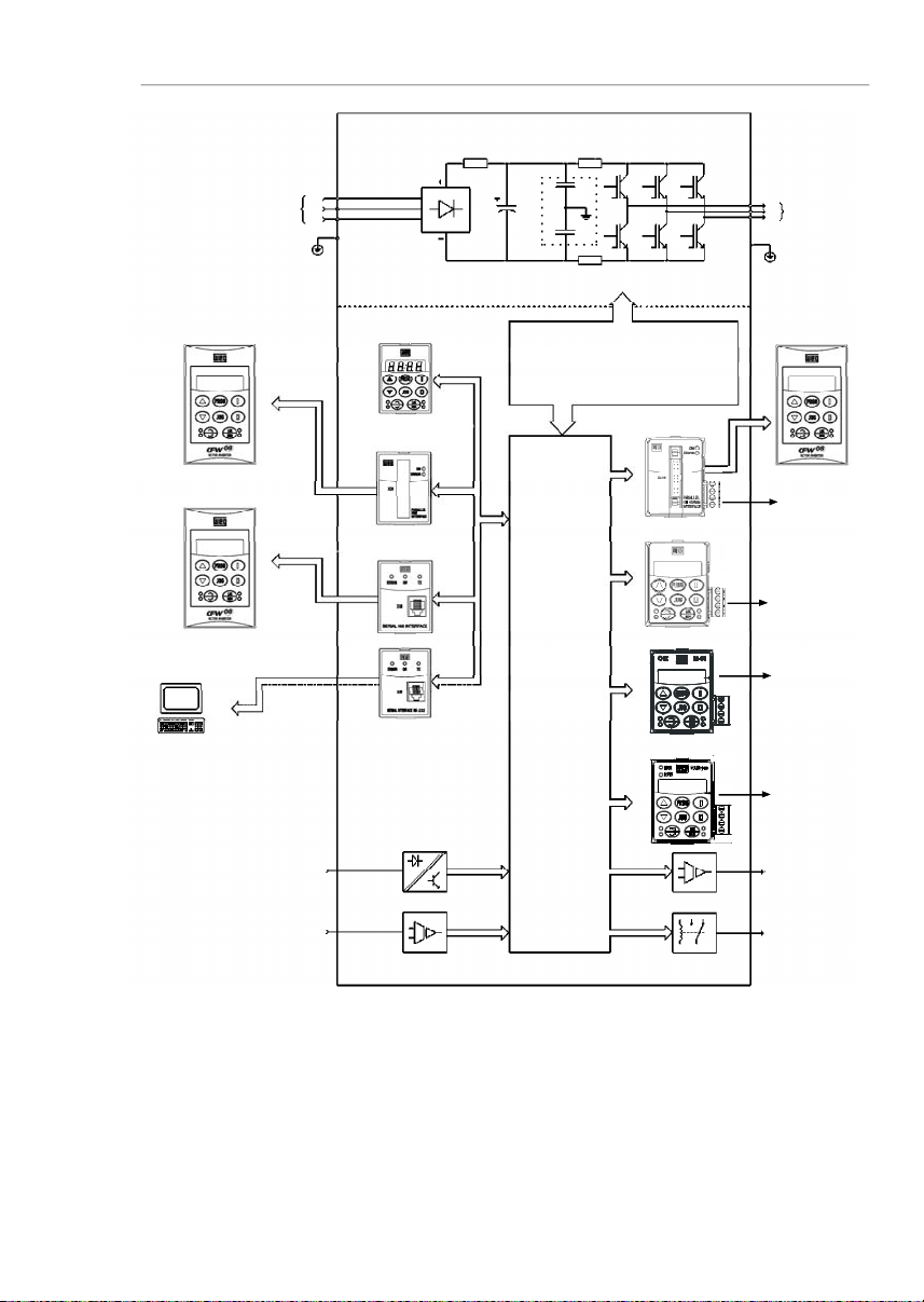
TheCFW-08frequencyinverterprovidestwocontroloptions:
vector control (VVC: voltage vector control) or V/F (scalar);
bothtypesof control can be setaccordingtotheapplication.
Inthevectorcontrolmode,themotorperformanceisoptimized
relatingto torque and speed regulation.
The"Self-Tuning"function,availableinvectorcontrol,permits
the automatic setting of the inverter parameter from the
identification(alsoautomatic)of the parametersof the motor
connectedatthe inverteroutput.
The V/F (scalar) mode is recommended for simpler
applicationssuchas pumpandfandrives.In thesecasesone
can reduce the motor and inverter losses by using the
"QuadraticV/F" option, thatresultsinenergysaving.
TheV/Fmodeisalsousedwhenmorethanonemotorshould
be driven simultaneously by one inverter (multimotor
application).
For power ratings and furthertechnical information, refer to
Chapter9.
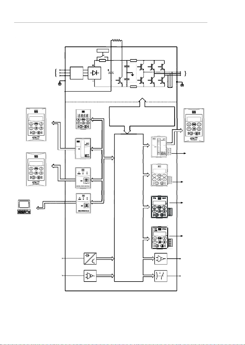
The block diagram below gives a general overview of the
CFW-08.
Page 22
21
CHAPTER 2 - GENERAL INFORMATION
Figure 2.1
- Block diagram for the models:
1.6-2.6-4.0-7.0A/200-240V and 1.0-1.6-2.6-4.0A/380-480V
Power
Supply
RST
PE
HMI-CFW08-RS
PC-Software
SuperDrive
Analog
Inputs
(AI1andAI2)
Digital
Inputs
(DI1to DI4)
Interface
RS-232KCS-CFW08
Interface
MIS-CFW08-RS
or
HMI-CFW08-P
POWER
CONTROL
POWER SUPPLIESAND
CONTROL/POWER
INTERFACES
"ECC3"
CONTROL
BOARD
WITHDSP
Motor
UVW
Rsh2
Rsh1
NTC
PE
RFIFilter
HMI-CFW08-RP
Interface
MIP-CFW08-RP
or
or
Analog
Output
(AO)
Relay
Output
(RL1andRL2)
CANopen
or
DeviceNet
KRS-485
KFB-COorKFB-DN
RS-485
24 V Power
Supply
24 V Power
Supply
HMI-CFW08-RP
KDC-24VR-CFW08
KDC-24V-CFW08
Page 23
22
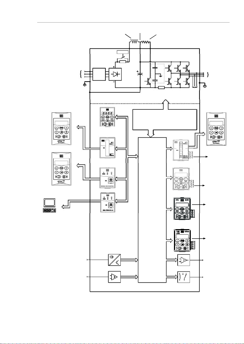
CHAPTER 2 - GENERAL INFORMATION
Figure 2.2
- Block diagram for the models:
7.3-10-16-22 A/200-240Vand 2.7-4.3-6.5-10-13-16A/380-480V
Note:
models 16 A and 22 A/200-240 V are not fitted with optional RFI filter.
Redede
Alimentação
R
STRFI
Suppressor
Filter
(optional)
HMI-CFW08-RS
PC-Software
SuperDrive
Analog
Inputs
(AI1andAI2)
Digital
Inputs
(DI1to DI4)
Interface
RS-232KCS-CFW08
Interface
MIS-
CFW08-RS
HMI-CFW08-P
POWER
CONTROL
POWER SUPPLIESAND CONTROL
/POWERINTERFACES
"ECC3"
CONTROL
BOARD
WITHDSP
Motor
UVW
Rsh2
Rsh1
RPC
Pré-Carga
Braking Resistor
(Externaland Optional)
BR
+UD
PE
-UD
Voltage
Feedback
PE
or
or
RFI
Filter
or
Interface
MIP-
CFW08-RP
HMI-CFW08-RP
Analog
Output
(AO)
Relay
Output
(RL1andRL2)
CANopen
or
DeviceNet
KRS-485
KFB-COorKFB-DN
RS-485
24 V Power
Supply
24 V Power
Supply
HMI-CFW08-RP
KDC-24VR-CFW08
KDC-24V-CFW08
Page 24
23
CHAPTER 2 - GENERAL INFORMATION
Figure 2.3
- Block diagram for the models:
28-33A/200-240 V and24-30 A/380-480 V
Note:
models 28 A and 33 A/200-240 V are not fitted with optional RFI filter.
Power
Supply
RST
RFI
Suppressor
Filter
(optional)
HMI-CFW08-RS
PC-Software
SuperDrive
Analog
Inputs
(AI1andAI2)
Digital
Inputs
(DI1to DI4)
Interface
RS-232KCS-CFW08
Interface
MIS-
CFW08-RS
HMI-CFW08-P
POWER
CONTROL
POWER SUPPLIESAND
CONTROL/POWER
INTERFACES
"ECC3"
CONTROL
BOARD
WITHDSP
Motor
UVW
Rsh1
RPC
Pré-Carga
Braking Resistor
(optional)
BR
DCRPE-UD
Voltage
Feedback
PE
or
or
RFI
Filter
or
Interface
MIP-
CFW08-RP
HMI-CFW08-RP
DCLink Inductor
(optional)
+UD
Analog
Output
(AO)
Relay
Output
(RL1andRL2)
CANopen
or
DeviceNet
KRS-485
KFB-COorKFB-DN
RS-485
24 V Power
Supply
24 V Power
Supply
HMI-CFW08-RP
KDC-24VR-CFW08
KDC-24V-CFW08
Page 25
24
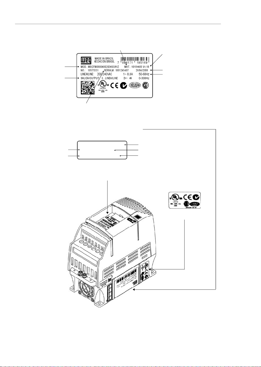
CHAPTER 2 - GENERAL INFORMATION
Figure 2.4
- Description and location of the nameplates on the CFW-08
2.4
CFW-08IDENTIFICATION
SoftwareVersion
ManufacturingDate
WEG Part Number
SerialNumber
CFW-08Model
(IntelligentCode)
RatedOutput Data
(Voltage, Frequency)
Lateral Label of the CFW-08
Frontal Nameplate of the CFW-08 (under the keypad)
Note:
toremove the
keypad,refer to the
instructions
inthe item 8.1.1
(figure8.2).
WEG Part Number
SerialNumber
CFW-08Model (IntelligentCode)
SoftwareVersion
ManufacturingDate
CertificationStiker
MSCFW080100T3848SOA1Z
10194356 V 4.18
1001208557 18/04/2008
RatedInputData
(Voltage,Current, etc)
Page 26

25
CHAPTER 2 - GENERAL INFORMATION
CFW-08
0040
B
2024
E
O
_ _
_ _
_ _
_ _
_ _
_ _
Z
Rated Output
Current for:
220 to 240 V:
0016 = 1.6 A
0026 = 2.6 A
0040 = 4.0 A
0070 = 7.0 A
0073 = 7.3 A
0100 = 10 A
0160 = 16 A
0220 = 22 A
0280 = 28 A
0330 = 33 A
380 to 480 V:
0010 = 1.0 A
0016 = 1.6 A
0026 = 2.6 A
0027 = 2.7 A
0040 = 4.0 A
0043 = 4.3 A
0065 = 6.5 A
0100 = 10 A
0130 = 13 A
0160 = 16 A
0240 = 24 A
0300 = 30 A
Number of
phases of
the power
supply:S = single
phase
T = three
phase
B = single
phase or
three phase
Manual
Language:P=Portuguese
E= English
S = Spanish
Power
Supply:2024 =
200to 240 V
3848 =
380 to 480 V
5060
(**)
=
500-600 V
Options:
S = standard
O = with
options
Degree of
Protection:
Blank=s
tandard
N1= Nema 1
N4= Nema
4X
(**)
Human
Machine
Interface:
Blank=standard
SI = without
interface
(with dummy
panel)
WEG Series 08
Frequency
Inverter
Control Board:
Blank=
standard
controlA1=c
ontrol 1
(Plus Version)A2=control2(Plus Version
with Als +/-
10 V)
A3 = control 3
(Plus version
with CANopen
protocol)
(*)
A4 = control 4
(Plus version
with
DeviceNet
protocol)
(*)
A5 = control
5
(**)
(for
Multipump
application)
Special
Software:
Blank=standard
EndCode
RFIFilter:
Blank=standard
FA=
CategoryC2RFI
filter
(internal or
footprint)
Special
Hardware:
Blank=standard
HOW TO SPECIFY THE CFW-08MODEL:
NOTES!
Theoption field (S or O)defines if theCFW-08 is a standard version or if it will be equippedwith anyoptional devices.Ifthe
standardversion is required, the specificationcodeendshere.
ThemodelnumberhasalwaystheletterZ at the end. For example:
CFW080040S2024ESZ=standard4.0ACFW-08inverter,single-phase at (200 to 240) V input,withmanual in English.
IftheCFW-08 is equipped with anyoptionaldevices, you must fill out all fields in the correct sequence up tothelastoptional
device,the model numberiscompletedwiththe letter Z.
Thus,for instance if the product above isrequired withNema 1 degree of protection:
CFW080040S2024EON1Z=
standardC
FW-08inverter,4.0A,single-phase,200-240V input,withmanualin Englishlanguage
and with kit for Nema1 degree of protection.
(*)-The versionsA3 and A4 of the control board shall be used only with the KFB-CO-CFW08 and with the KFB-DN-CFW08, respectively (refer to item 8.14 and 8.15). The parallel keypad, the
serial remote keypad, the parallel remote keypad, and the serial protocol (Modbus and WEG) cannot be used with these versions of the control board.
(**) -
For these models, contact WEG.
Page 27

26
CHAPTER 2 - GENERAL INFORMATION
Fortheeffectofthiscode,thestandardproduct is conceived
asfollows:
-CFW-08 with standard control board.
-
Degree of protection:
N
ema
1 for the models 22 A,
28 A and 33 A/ 200-400 V and also 13 A,16 A, 24 A
and 30 A/380-480 V, IP20 for the other models.
CFW-08 Plus - A1 is composed of the inverter and the
controlboard1. Example: CFW080040S2024PO
A1Z.CFW-08 Plus - A2 is composed of the inverter and the
control board 2. Example: CFW080040S2024PO
A2Z.Thesemodelsarefactorysetforbipolaranaloginputs(-10V
to +10 V).
Thisconfigurationislostwhenthefactorydefaultparameters
areloaded (P204 = 5). Refer to the detailed descriptionof
parametersP204 andP235forfurtherinformation.
CFW-08 Plus - A3 is composed of the inverter, the KFB-
CO-CFW08kitandtheCANopencommunicationprotocol.
Example:CFW-080040S2024PO
A3Z.CFW-08 Plus - A4 is composed of the inverter, the KFB-
DN-CFW08kitandtheDeviceNetcommunicationprotocol.
Example:CFW080040S2024PO
A4Z.CFW-08 Multipump -A5 is composed of the inverter and
thecontrolboard5,usedformultipumpsystemapplications.
7.0A, 16.0 A, 22 A, 28 A and 33 A /200-240 V and for all
380-480 V models are just available with three-phase
powersupply.
A Category C2 RFI filter (optional)can be installedinside
the inverter in models 7.3 A and 10 A/200-240 V (single-
phase) and 2.7A, 4.3 A, 6.5 A, 10 A, 13 A, 16A, 24 A and
30A/380-480 V.Models 1.6A, 2.6A and 4.0A/200-240 V
(single-phase)and 1.0A, 1.6A, 2.6Aand4.0A/380-480V
can be providedmounted on a footprint CategoryC2 RFI
filter(optional).
Thelistingoftheexistingmodels(voltage/current)isshown
initem 9.1.
Page 28

27
CHAPTER 2 - GENERAL INFORMATION
The CFW-08is supplied in cardboard boxes.
Theoutsideofthepackingboxhasa nameplatethatisidentical
tothat on the CFW-08.
Please check if the CFW-08is the one you ordered.
Checkifthe:
CFW-08nameplatedatamatcheswithyourpurchaseorder.
Theequipmenthas not been damaged duringtransport.
Ifanyproblem isdetected,contactthe carrier immediately.
If the CFW-08 is not installed immediately,store it in a clean
anddryroom(storage temperatures between -25 °C [-13 °F]
and 60 °C [140 ºF]). Cover it to protect against dust, dirt or
othercontamination.
ATTENTION!
When theinverterisstoredfor alongtime,it is recommended
to power the inverter up for 1 hour every year. Make sure to
use a power supply with the following characteristics for all
models (200-240 V or 380-480 V): 220 V, single-phase or
three-phase,50 Hz or 60 Hz, withoutconnectingthemotorto
thedriveoutput.Afterpoweringupthe drive,keepitoff for 24
hoursbeforeusingitagain.
2.5
RECEIVING
AND
STORING
Page 29
28
CHAPTER3
INSTALLATION ANDCONNECTION
Thischapterdescribestheproceduresforthe electricaland
mechanicalinstallationoftheCFW-08.Theseguidelines
andsuggestionsmust be followed for proper CFW-08
operation.
The location of the inverterinstallation is an important factor
to assure good performance and long useful life for its
components. For proper installation, we make the following
recommendations:
Avoid direct exposure to sunlight, rain, high moisture and
sea air;
Avoidexposuretoexplosiveorcorrosivegasesandliquids;
Avoid exposure to excessive vibration, dust, oil or any
conductiveparticles in the air.
Environment conditions:
Temperature: 0 ºC to 40 ºC (32 ºF to 104 ºF ) - nominal
conditions.From40ºCto50 ºC (32ºF to122ºF)-with2%
currentderatingfor each 1 ºC (1.8 ºF) degreeabove40 ºC
(104ºF).
Relativeairhumidity:5 % to 90 %-non-condensing.
Maximumaltitude: 1000m (3,300ft) -nominalconditions.
From 1000 m to 4000 m (3,300 to 13123.3 ft) - with 1 %
currentreduction for each 100 m (328 ft) above 1000 m
(3,300ft).
From2000m (6561.6ft) to 4000 m (13123.3ft)- avoltage
reduction of 1.1 % every 100 m (328 ft) above 2000 m
(6561.6ft).
Pollution degree: 2 (according to EN50178 and UL508C)
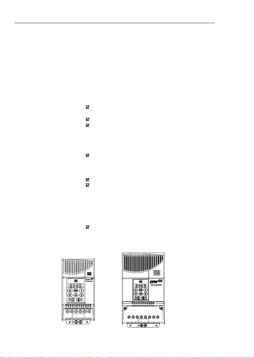
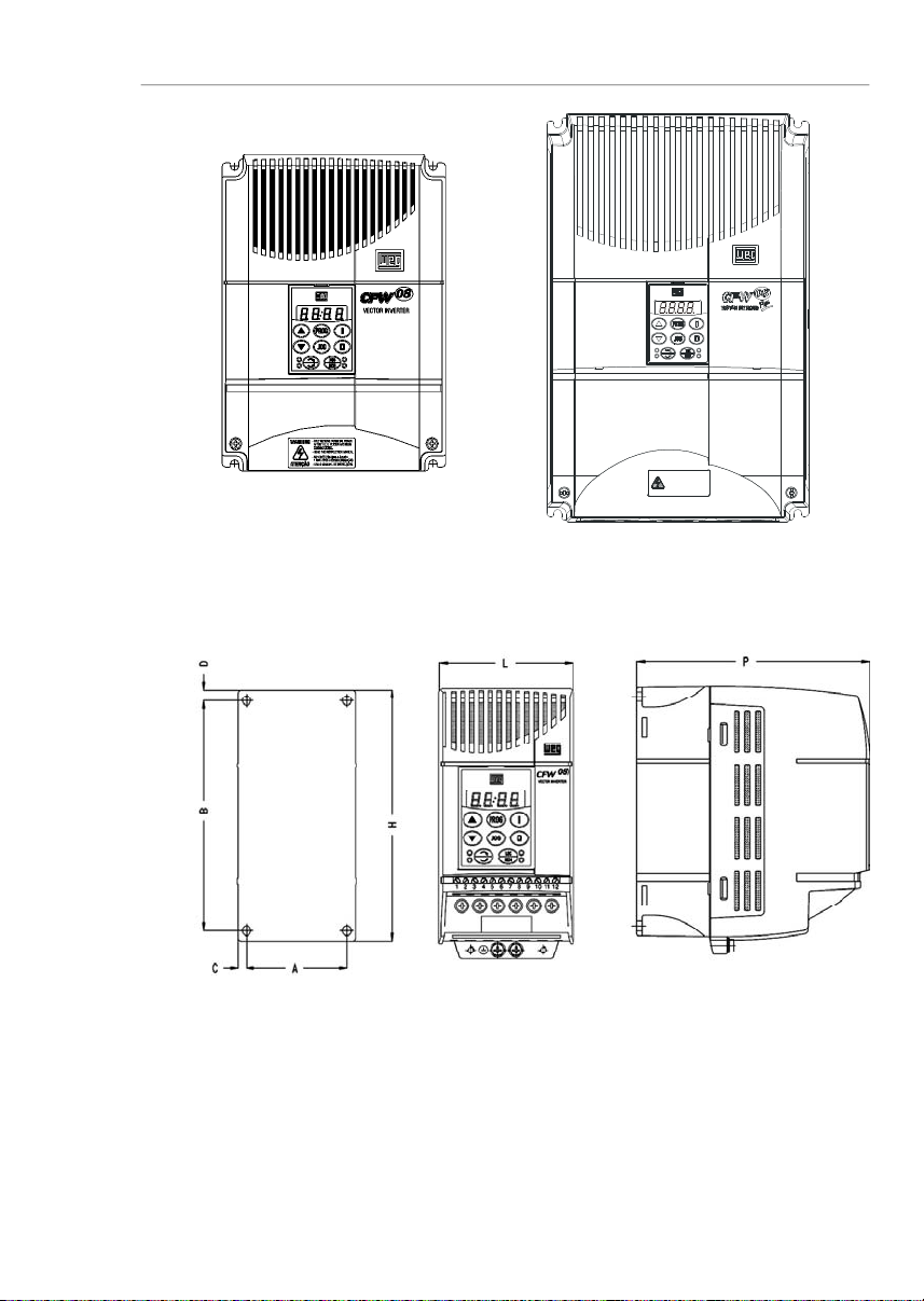
The figure 3.1 and the table 3.1, provides external mounting
specifications,and externalfixingholesof theCFW-08.
3.1
MECHANICAL
INSTALLATION
3.1.1
Environment
3.1.2
CFW-08Mounting
Specifications
Figure 3.1
- CFW-08 mounting specifications
Page 30
29
CHAPTER 3 - INSTALLATION
AND CONNECTION
Figure 3.1 (cont.)
- CFW-08 mounting specifications
VIEW OF THE
MOUNTINGBASE
FRONTAL
VIEW
LATERALVIEW
1MIN.A PÓSADESENERGIZAÇÃO.
-SOMENTE REMOVAATAMPA
-LEIA OMANUALDE INSTRUÇÕES.
ATENÇÃO
-READ THEINSTRUCTIONSMA NUAL.
AFTER1 MIN.POWERHA SBEEN
-ONLYREMOVE TERMINALCOVER
WARNING
DISCONNECTED.
Page 31

30
CHAPTER 3 - INSTALLATION
AND CONNECTION
Inverter
Model
1.6A / 200-240 V
2.6A / 200-240 V
4.0A / 200-240 V
7.0A / 200-240 V
7.3A / 200-240 V
10A / 200-240 V
16A / 200-240 V
22A/200-240V
28A/200-240V
33A/200-240V
1.0A / 380-480 V
1.6A / 380-480 V
2.6A / 380-480 V
2.7A / 380-480 V
4.0A / 380-480 V
4.3A / 380-480 V
6.5A / 380-480 V
10A / 380-480 V
13A / 380-480 V
16A / 380-480 V
24A/380-480V
30A/380-480V
Width L
mm
(in)75(2.95)75(2.95)75(2.95)75(2.95)
115
(4.53)
115
(4.53)
115
(4.53)
143
(5.63)
182
(7.16)
182
(7.16)75(2.95)75(2.95)75(2.95)
115
(4.53)75(2.95)
115
(4.53)
115
(4.53)
115
(4.53)
143
(5.63)
143
(5.63)
182
(7.16)
182
(7.16)
HeightH
mm
(in)
151
(5.95)
151
(5.95)
151
(5.95)
151
(5.95)
200
(7.87)
200
(7.87)
200
(7.87)
203
(7.99)
290
(11.41)
290
(11.41)
151
(5.95)
151
(5.95)
151
(5.95)
200
(7.87)
151
(5.95)
200
(7.87)
200
(7.87)
200
(7.87)
203
(7.99)
203
(7.99)
290
(11.41)
290
(11.41)
Depth P
mm
(in)
131
(5.16)
131
(5.16)
131
(5.16)
131
(5.16)
150
(5.91)
150
(5.91)
150
(5.91)
165
(6.50)
196
(7.71)
196
(7.71)
131
(5.16)
131
(5.16)
131
(5.16)
150
(5.91)
131
(5.16)
150
(5.91)
150
(5.91)
150
(5.91)
165
(6.50)
165
(6.50)
196
(7.71)
196
(7.71)Amm
(in)64(2.52)64(2.52)64(2.52)64(2.52)
101
(3.98)
101
(3.98)
101
(3.98)
121
(4.76)
161
(6.33)
161
(6.33)
64
(2.52)
64
(2.52)64(2.52)
101
(3.98)64(2.52)
101
(3.98)
101
(3.98)
101
(3.98)
121
(4.76)
121
(4.76)
161
(6.33)
161
(6.33)Bmm
(in)
129
(5.08)
129
(5.08)
129
(5.08)
129
(5.08)
177
(6.97)
177
(6.97)
177
(6.97)
180
(7.08)
260
(10.23)
260
(10.23)
129
(5.08)
129
(5.08)
129
(5.08)
177
(6.97)
129
(5.08)
177
(6.97)
177
(6.97)
177
(6.97)
180
(7.09)
180
(7.09)
260
(10.23)
260
(10.23)
Cmm(in)5(0.20)5(0.20)5(0.20)5(0.20)7(0.28)7(0.28)7(0.28)11(0.43)11(0.43)11(0.43)5(0.20)5(0.20)5(0.20)7(0.28)5(0.20)7(0.28)7(0.28)7(0.28)11(0.43)11(0.43)11(0.43)11(0.43)Dmm
(in)6(0.24)6(0.24)6(0.24)6(0.24)5(0.20)5(0.20)5(0.20)10(0.39)10(0.39)10(0.39)6(0.24)6(0.24)6(0.24)5(0.20)6(0.24)5(0.20)5(0.20)5(0.20)10(0.39)10(0.39)10(0.39)10(0.39)
Mounting
ScrewM4(5/32)M4(5/32)M4(5/32)M4(5/32)M4(5/32)M4(5/32)M4(5/32)
M5
(3/16)
M5
(3/16)M5(3/16)M4(5/32)M4(5/32)M4(5/32)M4(5/32)M4(5/32)M4(5/32)M4(5/32)M4(5/32)M5(3/16)M5(3/16)M5(3/16)M5(3/16)
Weigth
kg
(lb)
1.0
(2.2)
1.0
(2.2)
1.0
(2.2)
1.0
(2.2)
2.0
(4.4)
2.0
(4.4)
2.0
(4.4)
2.5
(9.8)
6
(2.36)6(2.36)
1.0
(2.2)
1.0
(2.2)
1.0
(2.2)
2.0
(4.4)
1.0
(2.2)
2.0
(4.4)
2.0
(4.4)
2.0
(4.4)
2.5
(5.5)
2.5
(5.5)6(2.36)6(2.36)
Degreeof
Protection
IP20 / Nema 1
(*)
IP20 / Nema 1
(*)
IP20 / Nema 1
(*)
IP20 / Nema 1
(*)
IP20 / Nema 1
(*)
IP20 / Nema 1
(*)
IP20 / Nema 1
(*)
IP20/Nema1
IP20/Nema1
IP20/Nema1
IP20 / Nema 1
(*)
IP20 / Nema 1
(*)
IP20 / Nema 1
(*)
IP20 / Nema 1
(*)
IP20 / Nema 1
(*)
IP20 / Nema 1
(*)
IP20 / Nema 1
(*)
IP20 / Nema 1
(*)
IP20 / Nema 1
IP20 / Nema 1
IP20 / Nema 1
IP20 / Nema 1
Dimensions
Fixing base
Table 3.1
- CFW-08 dimensions for mechanical installation of the several models
(*)
These modelsare Nema 1 only withthe KN1-CFW08-MX optional.
Page 32

31
CHAPTER 3 - INSTALLATION
AND CONNECTION
When installingtheCFW-08,free spacearound the inverter
must be left as indicated in figure 3.2.
Table 3.2 shows the
required free spaces.
Installtheinverterinverticalpositionaccordingtothefollowing
recommendations:
1)
Installtheinverterona flat surface.
2)Donotinstallheatsensitivecomponentsimmediatelyabove
the
inverter.
ATTENTION!
When inverters are installed side by side, maintain the
minimumrecommendeddistanceB.
W
hen inverters are installed top and bottom, maintain the
minimum recommended distance
A+ C and deflect the hot
aircomingfrom theinverterbelow.
ATTENTION!
Provide independent conduits for signal, control and power
conductorsseparation(refertoitem3.2-ElectricalInstallation).
Useseparateconduitsortrunkingforcontrolandpowerwiring
(seeitem 3.2 - Electrical Installation).
Figure 3.2
- Free spaces for cooling
3.1.3
Positioningand Fixing
Page 33

32
CHAPTER 3 - INSTALLATION
AND CONNECTION
CFW-08Model
1.6A / 200-240 V
2.6A / 200-240 V
4.0A / 200-240 V
7.0A / 200-240 V
1.0A / 380-480 V
1.6A / 380-480 V
2.6A / 380-480 V
4.0A / 380-480 V
7.3A / 200-240 V
10A / 200-240 V
16A / 200-240 V
2.7A / 380-480 V
4.3A / 380-480 V
6.5A / 380-480 V
10A / 380-480 V
22A / 200-240 V
13A / 380-480 V
16A / 380-480 V
28A/200-240V
33A/200-240V
24A/380-480V
30A/380-480V
ABCD30 mm
1.18 in
5 mm
0.20 in
50 mm
2 in
50 mm
2 in
35 mm
1.38 in
15 mm
0.59 in
50 mm
2 in
50 mm
2 in
40 mm
1.57 in
30 mm
1.18 in
50 mm
2 in
50 mm
2 in
50 mm
2 in
40 mm
1.57 in
60 mm
2.36 in
50 mm
2 in
Table 3.2
- Recommendedfree spaces
When invertersare installedinside closedmetallic panels or
boxes provide suitable air exhaustion by ensuring that the
ambient temperature remains within the allowed range. For
wattlosses refer to item 9.1of this manual.
For reference, table 3.3 shows the cooling airflow for each
invertermodel.
Inverter Cooling Method:
internal fan, flow direction from
thebottomto the top.
3.1.3.1
PanelMounting
Table 3.3
- Coolingair flow requirements
CFW-08 Inverter Model
CFM
I/s
m3/min
4.0
A, 7.0
A/200V2.6
A, 4.0
A/400V6.0
2.8
0.17
7.3
A, 10
A, 16
A/200V6.5
A, 10
A/400V18.0
8.5
0.5113A, 16
A/400V18.0
8.5
0.5122A/200V22.0
10.4
0.6228A/200V24
A/400V36.0
17.0
1.0233A/200V30
A/400V44.0
20.8
1.25
Page 34

33
CHAPTER 3 - INSTALLATION
AND CONNECTION
3.1.3.2
SurfaceMounting
Figure 3.3 shows the surface installation procedures of the
CFW-08.
Figure 3.3
- Mounting procedures for CFW-08
3.2
ELECTRICAL
INSTALLATION
DANGER!
The information below will be a guide to achieve a proper
installation. Also follow all applicable local standards for
electricalinstallations.
DANGER!
Be sure the AC input power has been disconnected before
makinganyterminalconnection.
DANGER!
Do not use the CFW-08 as an emergencystop device. For
thispurposeprovideother additional mechanical means.
Thepowerconnectionterminalscanbe of differentsizesand
configurations,dependingontheinvertermodel,as shownin
figure3.4.
Descriptionofthepowerterminals:
L/L1,N/L2 and L3 (R, S ,T):AC powersupply.
Themodels of thelinevoltage200-240V (excepting7.0A,
16A, 22A, 28A, and33A) canbeoperatedon twophases
(single-phaseoperation)withoutratedcurrentreduction.In
this case the AC power supplycan be connected to any2
terminalsof the 3 inputsterminals.
U,V,W: connectiontothemotor.
3.2.1
Power/ Grounding
Terminals
AIR FLUX
Page 35

34
CHAPTER 3 - INSTALLATION
AND CONNECTION
-UD:negativepoleof the DClinkcircuitis notavailable on
themodels 1.6A-2.6A-4.0A-7.0A/200-240V and models
1.0 A-1.6 A-2.6 A-4.0 A/380-480 V. It is used when the
invertersuppliedby DC voltage(withtheterminal+UD).In
order to avoid an incorrect braking resistor connection
(mountedoutsidethe inverter),thereis a protectiverubber
plug on this terminal, which must be removed if the –UD
terminalhastobeused.
BR:Connectionforthebrakingresistor.
Notavailableonthemodels1.6A-2.6A-4.0A-7.0A/200-240V
andonthemodels1.0A-1.6A-2.6A-4.0A/380-480V.
+UD: positive pole of the DC link circuit, notavailable on
the models 1.6A-2.6 A-4.0A-7.0A/200-240V and on the
models 1.0 A-1.6 A-2.6 A-4.0 A/380-480 V. It is used to
connectthebrakingresistor(withtheBR terminal)orwhen
the inverter shall be supplied by with DC voltage (jointly
withthe –UDterminal.
DCR: Connection for the external DC link circuit inductor
(optional).Itisonlyavailable on themodels28Aand 33A/
200-240 V and on the models 24 Aand 30 A/380-480 V.
c) 22 A/200-240 V and 13-16A/380-480 V models
b)7.3-10-16A/200-240 V and2.7-4.3-6.5-10A/380-480V models
a)1.6-2.6-4.0-7.0A/200-240 Vand 1.0-1.6-2.6-4.0A/380-480 Vmodels
Figure 3.4 a) to c)
- Power terminals
L3UVWL/L1
N/L2
-Ud
BR+Ud
L3
L/L1
N/L2
UVW1R2S3T4U5V6W7-UD8BR9+UD
LINE
MOTOR
Page 36

35
CHAPTER 3 - INSTALLATION
AND CONNECTION
3.2.2
Location of the Power
Terminals,Grounding
TerminalsandControl
TerminalConnections
ControlXC1
Power
Grounding
a)1.6-2.6-4.0-7.0-7.3-10-16A/200-240Vand
1.0-1.6-2.6-2.7-4.0-4.3-6.5-10A/380-480Vmodels
Figure 3.5 a) and b)
- Location of the power, grounding and
control connections
b)22-28-33A/200-240V and 13-16-24-30A/380-480 V models
ControlXC1
Power
Grounding
Figure 3.4 (cont.) d)
- Power terminals
d) 28-33 A/200-240V and 24-30A/380-480 V models
1R2S3T4U5V6W7
-UD8BR9+UD
LINE
MOTOR10DCR
Page 37

36
CHAPTER 3 - INSTALLATION
AND CONNECTION
3.2.3
Power/Grounding
Wiringand
Circuit Breakers
ATTENTION!
Install the inverter and power cables distant from sensitive
equipmentand wiringsby0.25m (0.82 ft),forinstancePLCs,
temperaturecontrollers,thermocouplecables,etc.
Usetherecommendedwirecrosssectionandcircuitbreakers
as shownin table 3.4. Use onlycopper wire (70 ºC [158 ºF]).
NOTE!
Thewire sizing in table3.4shallbeusedas reference values
only. The exact wire sizing depends on the installation
conditionsand the maximum acceptable line voltage drop.
Therecommendedtightening torque is shownintable3.5.
ATTENTION!
The use of mini circuit breakers (MBU) is not recommended
duetothelevel of the magneticprotection.
Table 3.4
- Recommendedwiring and circuit breakers – use only copper wire (70 ºC [158 ºF])
Page 38

37
CHAPTER 3 - INSTALLATION
AND CONNECTION
Model
1.6A / 200-240 V
2.6A / 200-240 V
4.0A / 200-240 V
7.0A / 200-240 V
7.3A / 200-240 V
10.0A / 200-240 V
16.0A / 200-240 V
22.0A / 200-240 V
28.0A / 200-240 V
33.0A / 200-240 V
1.0A / 380-480 V
1.6A / 380-480 V
2.6A / 380-480 V
2.7A / 380-480 V
4.0A / 380-480 V
4.3A / 380-480 V
6.5A / 380-480 V
10.0A / 380-480 V
13.0A / 380-480 V
16.0A / 380-480 V
24.0A / 380-480 V
30.0A / 380-480 V
GroundingWiring
N.m
Lbf.in
0.5
4.34
0.5
4.34
0.5
4.34
0.5
4.34
0.5
4.34
0.5
4.34
0.5
4.34
0.5
4.34
0.5
4.34
0.5
4.34
0.5
4.34
0.5
4.34
0.5
4.34
0.5
4.34
0.5
4.34
0.5
4.34
0.5
4.34
0.5
4.34
0.5
4.34
0.5
4.34
0.5
4.34
0.5
4.34
Power Cables
N.m
Lbf.in
1.0
8.68
1.0
8.68
1.0
8.68
1.0
8.68
1.76
15.62
1.76
15.62
1.76
15.62
1.76
15.62
1.76
15.62
1.76
15.62
1.2
10.0
1.2
10.0
1.2
10.0
1.76
15.62
1.2
10.0
1.76
15.62
1.76
15.62
1.76
15.62
1.76
15.62
1.76
15.62
1.76
15.62
1.76
15.62
Table 3.5
- Recommended tighteningtorque for power andgrounding connections
3.2.4
PowerConnections
a) 1.6-2.6-4.0-7.0A/200-240 V and 1.0-1.6-2.6-4.0A/380-480V models - Threephase power supply
Typeof Screwdriverfor
thePowerTerminal
Philips Number PH2
Philips Number PH2
Philips Number PH2
Philips Number PH2
Philips Number PH2
Philips Number PH2
Philips Number PH2
PhilipsNumber PH2
PozidrivNumber PZ2
PozidrivNumberPZ2
PhilipsNumber PH2
Philips Number PH2
Philips Number PH2
Philips Number PH2
Philips Number PH2
Philips Number PH2
Philips Number PH2
Philips Number PH2
Philips Number PH2
Philips Number PH2
PozidrivNumberPZ2
PozidrivNumberPZ2
Figure 3.6 a)
- Powerand grounding connections
PERSTPowerSupply
CircuitBreaker
PE
T
Q1
R
STUVW
PE
Shielding
PEWV
U
Page 39

38
CHAPTER 3 - INSTALLATION
AND CONNECTION
c) 1.6-2.6-4.0-7.3-10A/ 200-240 V models - Singlephase power supply
Figure 3.6 b) and c)
- Powerand grounding connections
(*)
Incase of single-phase powersupply with phase and neutral cable, connect only the phasecable to the
circuit breaker.
(**)
In the 1.6A -2.6 A and 4.0A models, the terminals to connect the braking resistor are not available.
PE
PE
T
Q1
RSTUVWPE
Shielding
PE
-Ud
BR+Ud
Braking
Resistor
(**)
(referto item
8.23)
WVU
Phase
Neutral
PowerSupply
Circuit Breaker
(*)
b) 7.3-10-16-22A/200-240 V and 2.7-4.3-6.5-10-13-16A/380-480V models -Three phase powersupply
PERSTPowerSupply
PE
T
Q1
RSTUVWPE
Shielding
PE
-Ud
BR+Ud
Braking
Resistor
(referto item
8.23)
WVU
CircuitBreaker
Page 40

39
CHAPTER 3 - INSTALLATION
AND CONNECTION
Figure 3.6 d)
- Powerand grounding connections
d) 28-33A / 200-240V and 24-30A / 380-480 V models - Three phase powersupply
DANGER!
Provide anAC disconnecting switch to switch OFF the input
powertothe inverter. Thisdeviceshalldisconnecttheinverter
from the AC input supply when required (e. g. during
maintenanceservices).
ATTENTION!
Acontactoror anotherdevicethatfrequentlydisconnectsand
reapplies the AC supply to the inverter in order to startand
stop the motor may cause damage to the inverter power
section.The driveis designed to use control input signals for
startingand stoppingthe motor.Ifused,theinputdevicemust
not exceed one operation every 6 minutes otherwise the
invertermay be damaged.
ATTENTION!
TheAC input for the inverter must have a grounded neutral
conductor.
NOTE!
TheACinputmustbecompatiblewiththeinverterratedvoltage
Power supply line capacity:
30kArms symmetrical amperes, 200-480 Vacmaximum,
whenprotected by fuses ratedmaximum of 200 % device
inputcurrent. Voltageis thesameasthedevicemaximum
inputvoltage. Inordertocomplywith theUL standard,UL
recognizedfuses must be used.
3.2.4.1
ACInput Connection
PE
T
Q1
RSTUVWPE
Shielding
PE
-Ud
BR+Ud
Braking Resistor
WVU
Phase
PowerSupply
DCR
DCLink
Inductor
(Optional)
PE
RST
CircuitBreaker
Page 41

40
CHAPTER 3 - INSTALLATION
AND CONNECTION
3.2.4.3
Grounding
Connections
IftheCFW-08isinstalledinnetworkswhichcansupplymore
than 30.000 Arms, you must provide suitable protection
circuitssuchasfuses and circuit breakers.
DC link inductor / line reactors
Therequirementsforuseofline reactorsorDC link inductor
dependonseveral application factors. Refer to item8.21.
NOTE!
Capacitorsfor power factor correctionarenotrequiredatthe
input(L/L1,N/L2,L3orR,S,T)andtheymustnotbeconnected
atthe output (U,V,W).
The inverter is provided with electronic protection against
motoroverload.This protection must be set according to the
specificmotor.Whenthesameinverterdrivesseveralmotors,
use individual overload relays for each motor. Maintain the
electricalcontinuityofthemotor cable shield.
ATTENTION!
If a disconnect switch or a contactor is inserted in the motor
supplyline, do not operatethem with motor running or when
inverter is enabled. Maintain the electrical continuity of the
motorcable shield.
Dynamic braking (DB)
When inverterswith dynamic braking (DB) are used, the DB
resistorshall be mountedexternally. Figure 8.31 shows how
to connect the braking resistor. Size it according to the
application,notexceedingthemaximumcurrentof thebraking
circuit. For the connection betweeninverter and the braking
resistor, use twisted cable. Provide physical separation
betweenthis cable and the signal and control cables. When
the DB resistor is mounted inside the panel, consider watt
lossgeneratedwhendefining thepanelventilation.
DANGER!
Theinvertermustbe grounded to a protective earth (PE) for
safetypurposes.
The earth or ground connection must comply with the local
regulations.Forgrounding,use cableswithcrosssectionsas
indicated in table 3.4. Make the ground connection to a
grounding bar or tothe generalgrounding point (resistance
10 ohms).
DANGER!
Do not share the ground wiring with other equipment that
operateswithhighcurrents(forinstance:highvoltagemotors,
weldingmachines,etc).Ifseveralinvertersareusedtogether,
refertofigure 3.7.
3.2.4.2
Output
Connections
Page 42

41
CHAPTER 3 - INSTALLATION
AND CONNECTION
ATTENTION!
TheAC input for the inverter must have a grounded neutral
conductor.
EMI – Electromagnetic interference
When electromagnetic interference (EMI) generated by the
inverterinterferesintheperformanceofotherequipment,use
shieldedwires, or install themotorwiresin metallic conduits.
Connect one end of the shielding to the inverter grounding
pointandtheotherend to the motor frame.
Motor frame
Alwaysgroundthemotorframe.Groundthemotorinthepanel
wherethe inverter is installedorgroundittotheinverter.The
inverter output wiring must be laid separately from the input
wiringas wellasfromthe control and signal cables.
NOTE!
Donotuseneutral conductorfor groundingpurposes.
Figure 3.7
- Grounding connections for more than one inverter
GROUNDING BAR
INTERNAL
T
O THE P
ANEL
Page 43

42
CHAPTER 3 - INSTALLATION
AND CONNECTION
3.2.5
Signaland Control
Connections
The
signalconnections
(analog inputs/outputs
)
andcontrol
connections (
digital inputs and relay outputs
)
are
made on
the XC1 connector of control board (
refertothe
location in
f
igure 3.5,
item
3.2.2).
There are two configurationsfor the control board: standard
version (CFW-08 line)
andPlusversion(CFW-08Plusline),
asshownbelow:
Figure 3.8
- XC1 control terminal description (standard control board - CFW-08)
Note:
NC = Normally Closed Contact, NO = NormallyOpen Contact.
XC1Terminal
1
DI1
2
DI2
3
DI34DI45GND6AI1or
DI5or
PTC17+10 V8GND910
N.C.11Commom
12
N.O.
Description
FactoryDefault Function
Digital Input1
GeneralEnable
Digital Input2
FWD / REV
Digital Input3
Reset
Digital Input4
Start/Stop
0V Reference
Analog Input 1 or Digital Input 5
orPTC Input
Frequency/Speed Reference
(remotemode)
PotentiometerReference
0V Reference
NotUsed
Relay Output 1 - N.C. Contact
No Fault (P277 = 7)
Relay1 Common Point
Relay 1 - N.O. Contact
No Fault (P277 = 7)
Specifications
4 isolates digital inputs
- Logic NPN
Minimum high level:10 Vdc
Maximum high level: 30 Vdc
Maximum low level: 3 Vdc
- Logic PNP
Maximum lowlevel: 10 Vdc
Minimum high level:21.5 Vdc
Maximum high level: 30 Vdc
Inputcurrent: -11mA
Maximum input current: -20 mA
Not connected to PE
( 0 to10) Vdc (0 to 20) mA (4 to 20)
mA(figure3.10)
Impedance:100 k
(voltage input)
and 500
(current input).
- Linearity error < 0,25 %
- Maximum voltage input: 30 Vdc
ForfurtherinformationrefertoP235
detailedparameterdescription
+10 Vdc, ± 5 %, capacity: 2 mA
Contact capacity:
0.5 A / 250 Vac
Relay 11012
11
CCW
CW
5k
FactoryDefault
Settings
Page 44

43
CHAPTER 3 - INSTALLATION
AND CONNECTION
Figure 3.9
- Description of the XC1 connector for the control board A1 (CFW-08 Plus), control board A2
(CFW-08 Plus with AIs -10 V a +10 V), control board A3 (CFW-08 Plus with CANopen protocol) and control
boardA4 (CFW-08 Plus with DeviceNet protocol)
Connector
XC11DI12DI23DI34DI45GND6AI1or
DI5or
PTC17+10 V8AI2or
DI6or
PTC29AO10N.C
11
Commom
12
N.O.
Description
FactoryDefault Function
Digital Input1
NoFunctionor GeneralEnable
Digital Input2
FWD / REV
Digital Input3
Reset
Digital Input4
No Function or Start/Stop
0V Reference
AnalogInput1orDigitalInput5
orPTC1 Input
Frequency/SpeedReference
(remotemode)
PotentiometerReference
Analog Input 2 or Digital Input
Digital 6 or PTC2Input
NotUsed
AnalogOutput
Output Frequency(Fs)
Relay 2 - N.C. Contact
Fs>Fx (P279 = 0)
RelaysCommon Points
Relay 1 - N.O. Contact
No Fault (P277 = 7)
Specifications
4 isolates digital inputs
- Logic NPN
Minimum high level:10 Vdc
Maximum high level: 30 Vdc
Maximum low level: 3 Vdc
- Logic PNP
Maximum lowlevel: 10 Vdc
Minimum high level:21.5 Vdc
Maximum high level: 30 Vdc
Inputcurrent: -11mA
Maximum
input current: -20 mA
Not connected to PE
(0to10)Vdcor(0to20)mAor(4to20)mA
and (-10 to +10) Vdc
(*)
(figure 3.10)
Impedance:100k
(voltageinput)and
500(currentinput)
- Linearity error < 0,25 %
- Maximum voltage input: 30 Vdc
For further information refer to P235
detailedparameterdescription
+10 Vdc, ± 5 %, capacity: 2 mA
(0to10) Vdcor (0 to 20)mA or (4 to
20)mA
and (-10 to +10) Vdc
(*)
(figure
3.10) Impedance:100 k
(voltage
input)and500
(currentinput)
- Linearityerror< 0.25 %
- Maximumvoltageinput:30 Vdc
Forfurtherinformation referto P239
detailedparameterdescription
(0to10)Vdc
or(0to20)mAor(4to20)mA,
RL10kResolution: 8 bits
Linearity Error < 0.25 %
Contact capacity:
0.5 A / 250 Vac
Relay 111Relay 21210
RPM
-
+
CCWCWCCW
CW
10k
Note:
NC = Normally Closed Contact, NO = NormallyOpen Contact.
(*)
Thisoption is availableonlyfor versionA2 of the controlboard (referto item 2.4).
In version A2 the linearity error is smaller than 0.50 %.
10k
FactoryDefault
Settings
Refer to item 2.4 for additional informationonthecontrolboards.
Page 45

44
CHAPTER 3 - INSTALLATION
AND CONNECTION
AI1AODI
AI2
Figure3.10
-
Jumperspositionfor selectingthe analoginputs and outputsoperationmode (voltage- 0 to 10 Vdc
or current - 0 to 20 mA / 4 to 20 mA) as wellas the digital inputsoperationmode (highlogic level - PNP or low
logic level - NPN). Refer to the digitalinputs definitionon items3.2.5.1 and 3.2.5.2
I/O
DI1to DI4
AO
AI1
AI2
FactoryDefault Setting
Refer to the parameters P263,
P264, P265and P266
OutputFrequency
Frequency/Speed Reference
(remotemode)
NoFunction
DIP
Switch
S1:1
S1:2
S1:3
S1:4
Selection
OFF: digital inputs as low active (NPN)
ON: digital inputs as high active (PNP)
ON: (0 to 10) Vdc
OFF: (4 to 20) mA or (0 to 20) mA
OFF: (0 to 10) Vdc or DI5
ON: (4 to 20) mA or (0 to 20) mA or PTC
OFF: (0 to 10) Vdc or DI6
ON: (4 to 20) mA or (0 to 20) mA or PTC
Table 3.6
- Dip switch configuration (inputs and outputs)
Asadefault,theanalog inputs and outputsaresettovoltage
mode (0 to 10) Vdc and the digital inputs are set to active
(NPNlogic).Change it byusingDIP switchS1(referto figure
3.10) on the control board and by setting parameters P235,
P239 and P253 (refer to table 3.6).
NOTE!
If it'suseda (4to20)mAsignal,setparameterP235,P239
and P253 that defines the signal type atAI1,AI2 and AO
respectively.
The parameters related to the analog inputs are: P221,
P222,P234,P235,P236, P238,P239, P240,P251,P252,
P253. For more details, please refer to chapter 6.
Page 46

45
CHAPTER 3 - INSTALLATION
AND CONNECTION
Inverter side
Insulatewith tape
Figure 3.11
- Shield connection
Connect to earth: bolts are
located on the heatsink
Donot ground
During the signal and control wire installation note the
following:
1)
Cable cross section: (0.5 to 1.5) mm²/(20 to 14)AWG
2)
MaximumTorque:0.50 N.m (4.50lbf.in).
3)
XC1 wiring must be connected with shielded cables and
installedatleast 10 cm (3.9 in) minimum separatelyfrom
otherwiring (power,control at 110/220V, etc) for lengths
up to 100 m (330 ft) and 25 cm (9.8 in) minimum for total
lengthsover100m (330ft).If the crossingof thesecables
isunavoidable, install them perpendicular, maintaining a
mimimumseparationdistanceof 5 cm(2in)atthecrossing
point.
Connectthe shield as shownbelow:
4)
Forwiringdistances longerthan50m (150ft),itisnecessary
touse galvanic isolators for the XC1:5 to 9 signals.
5)
Relays, contactors, solenoids or eletromagnetic braking
coilsinstalledneartheinverterscangenerateinterferences
inthe controlcircuit.Toeliminatethisinterference,connect
RC suppressor in parallel with the coils of AC relays.
Connectfree-wheeling diode in case ofDC relays.
6)
When external keypad (HMI) is used (refer to chapter 8),
separetethecable thatconnectsthe keypadto theinverter
fromothercables,maintaining aminimumdistanceof10cm
(3.9in) betweenthem.
7)
When analog reference (AI1 or AI2) is used and the
frequency oscillates (problem caused by eletromagnetic
interference)connectXC1:5to the inverterheatsink.
Page 47

46
CHAPTER 3 - INSTALLATION
AND CONNECTION
3.2.5.1
DigitalInputs as
LowLevel Active
(S1:1 to OFF)
Connector XC1
1
DI12DI23DI34DI45GND
b) Example using a PLC - NPN transistor output
Connector XC1
1
DI12DI23DI34DI45GND
Figure 3.12 a) and b) -
Digital inputs
as lowlogic level configuration
PLC output relay
COM
PLCoutput NPN
GND(PLC)
In these options, the equivalent circuit at inverter side is
presentedin thefigure3.13.
Thisoptioncanbeselectedwhena PLCisusedwithrelayor
transistoroutput is used (lowlogiclevel toactivatetheDI).
a) Example using a PLC - relay output
Figure 3.13
- Equivalent circuit – Digital inputs as low logic level
XC1:1
XC1:2
DI2
DI1122k2k
10 V
10 V
SMD
Optocoupler
SMD
Optocoupler
+12 V
S1:1 in OFF
GND
Page 48

47
CHAPTER 3 - INSTALLATION
AND CONNECTION
This option can be selected when a PLC is used with PNP
transistor output (high logic level to activate the DI) or PLC
with relay output is used. For this last alternative you must
applyanexternal powersupply24 V +/-10%.
3.2.5.2
DigitalInput as
HighLevelActive
(S1:1to ON)
Figure 3.14 a) and b
) - Configuration of the active digital inputs as
high logic level
In this option, the equivalent circuit at the inverter side is
presentedin thefigure3.15.
b) Example using a PLC - PNP transistor output
a) Example using a PLC - relay output
Connector XC1
1
DI12DI23DI34DI45GND
24 V (internal PLC)
PLCoutput
PNP
GND(PLC)
PLC output relay
GND(source
external24 V)
24 V (external)
Connector XC1
1
DI12DI23DI34DI45GND
Figure 3.15
-
Equivalent circuit - Digital inputs as high logic level
XC1:1
XC1:2
DI2
DI1122k10 V
10 V
SMD
Optocoupler
SMD
Optocoupler
+12 V
S1:1 in ON
2k
GND
Page 49

48
CHAPTER 3 - INSTALLATION
AND CONNECTION
DI1 - No Function or
GeneralEnabling
DI2 - FWD / REV
DI3- Reset
COM
AI1
+10 V
AI2
AO1
NC
CommonNODI4- No Function
or Start/Stop
S1: FWD/REV
S2: Reset
S3: Start/Stop
R1:Potentiometer for
speed setting
1234567891011
12
NOTES!
Theinverterisfactorydefault programmed with the digital
inputs as low level active (S1:1 in OFF). When the digital
inputsareusedashighlevelactive,youmustsetthejumper
S1:1to ON.
The jumper S1:1 selects the high level or low level active
forall 4 digitalinputs.Youcan not select them separately.
3.2.6
TypicalTerminal
Connections
Connection 1 - Keypad Start/Stop (local mode)
With the factory default programming, you can operate the
inverterin localmode withtheminimumconnectionsshownin
figure 3.6 (Power) and without control connections. This
operationmodeis recommendedfor userswho areoperating
the inverter for the first time. Note that there is no need of
connectionofcontrolterminals.
Forstart-up accordingtothisoperationmode,referto
c
hapter5.
Connection 2 - Wire Start/Stop (remote mode)
Validfor factorydefault programming and inverter operating
in remote mode. For the factory default programming, the
selection of the operation mode
(local/remot
e)is made via
thekey
(defaultislocal).
Thefigure3.16 showstheinverterterminalconnectionfor this
typeof driving.
Figure 3.16
- XC1 wiring for connection 2
R1
S3S2S15k
Page 50

49
CHAPTER 3 - INSTALLATION
AND CONNECTION
NOTES!
Fortheproperoperationofconfiguration2, terminal5 shall
beconnectedto terminal 1 (general enable).
Thefrequencyreference can be sent via AI1 analog input
(as shown in figure
3.16
), via keypad HMI-CFW08-P, or
viaany othersource(asdescribed
in
theparametersP221
and P222).
When a line fault occurs by using this type of connection
withswitchS3 atposition"RUN",themotor willbeenabled
automaticallyas soon as
thelineisre-established.
Connection 3 - Wire ON/OFF
Functionenabling(threewirecontrol):
Set DI1 to ON: P263 = 14
Set DI2 to OFF: P264 = 14
SetP229 = 1 (command via terminals) if you wantthe3-wire
controlin local mode.
SetP230 = 1 (command via terminals) if you wantthe3-wire
controlinremote mode.
Thefigure3.17belowshowstheconnectionsatVFDterminals
forthis typeofconfiguration.
S1: Start
S2: Stop
S3: Changes the
speeddirection
Figure 3.17
- XC1 wiring for connection 3
DI1- ON(3-wire)
DI2- OFF(3-wire)
DI3
COM
AI1
+10 V
AI2
AO1
NC
CommonNODI4 - FWD / REV
S2
S1
1234567891011
12
S3
Page 51

50
CHAPTER 3 - INSTALLATION
AND CONNECTION
NOTES!
S1
andS2are push buttons, start (NO contact) and stop
(NC
conta
ct),respectively.
The speed reference can be via analog input AI1 (as in
Connection2),viakeypad(HMI-CFW08-P),orviaanyother
source (as described in the parameters P221 and P222).
When a line fault occursby using this connection withthe
motor running and the S1 and S2 switches are in original
position (S1 openned and S2 closed), at the moment the
voltagereturnstheinverterwillnotbe enabledautomatically,
itwillonly beenabledif the S1 switchwereclosedagain(a
pulseattheStartdigitalinput).
TheStart/Stop functionisdescribedin chapter6.
Connection 4 - FWD/REV Function
Parameter to be programmed:
Set DI1 to ForwardRun: P263 = 8
SetDI2 to Reverse Run: P264=8
Make sure the inverter commands are via terminals, i.e.,
P229 = 1
to local mode or P230 = 1 to remote mode.
Thefigure 3.18belowshowsthe inverterterminalconnection
forthistypeof driving.
Figure 3.18
- XC1 wiring for connection 4
S1 open: Stop
S1 closed:Forward Run
S2 open: Stop
S2closed: ReverseRun
DI1- ForwardRun
DI2-ReverseRun
DI3- Reset
COM
AI1
+10 V
AI2
AO1
NC
CommonNODI4- No Function
S2
S1
1234567891011
12
NOTE!
For the correct operation of the connection 4, P266 must
be programmed as “Not Used”.
The speed reference can be via analog input AI1 (as in
connection2),viakeypad(HMI-CFW08-P),orvia anyother
source (refer to the description of parameters P221 and
P222).
When a linefault occurs,thisconnectionwithswitchS1 or
switchS2 isclosed, themotorwillbeenabledautomatically
as soon as the lineis re-established.
Page 52

51
CHAPTER 3 - INSTALLATION
AND CONNECTION
3.3
EUROPEAN EMC
DIRECTIVE-
REQUIREMENTS
FORCONFORMING
INST
ALLA
TIONS
TheCFW-08inverterserieswasdesignedconsideringsafety
andEMC(Electromagnetic Compatibility)aspects.
The CFW-08 units do not have an intrinsic function until
connectedwith other components (e.g.a motor).Therefore,
the basic product is not CE marked for compliance with the
EMC Directive. The end user takes personal responsibility
for the EMC compliance of the whole installation. However,
wheninstalled according totherecommendationsdescribed
inthe manual of theproductand includingtherecommended
filtersand EMCmeasurestheCFW-08fulfillallrequirements
of the EMC Directive (89/336/EEC) as defined by the
EMC
ProductStandard forAdjustableSpeed ElectricalPower
Drive Systems EN61800-3.
Compliance of the CFW-08series is based on the testing of
therepresentativemodels.ATechnicalConstructionFile was
checked and approved by a Competent Body.
3.3.1
Installation
Thefigure3.19showsthe EMC filters connection.
Figure 3.19
- EMC filters connection - general condition
OutputCMChoke
Transformer
Ground Rod/Grid
or Building Steel
Structure
Metallic Cabinet (when required)
Protective Grounding - PE
MotorPECFW-08
L2/N
L1/LL3EPEXC1
1 to 12UInputCM
Choke
Controling and Signal Wiring
VWPE
L1/L
L2/NL3External
Input RFI
FilterL2L1L3E
Obs.:
Single-phaseinput inverters use single-phase filters andonly L1/L and L2/N areused.
Thefollowingitemsarerequiredinordertohaveaconforming
installation:
1)
The motor cable must be armored, flexible armored or
installedinsideametallicconduitortrunkingwithequivalent
attenuation.Groundthescreen/metallicconduitatbothends
(inverterandmotor).
2)Controlandsignalwiringmustbeshieldedorinstalledinside
ametallicconduitortrunkingwithequivalentattenuation.
3) The inverter and the external filter must be mounted on a
commonmetallicbackplateincloseproximitytooneanother.
Ensurethat a good electricalconnection is made between
theheatsink(inverter)
,
the
frame(externalfilter)andtheback
plate.52CHAPTER 3 - INSTALLATION
Page 53

AND CONNECTION
3.3.2
EmissionandImmunity
LevelsDescription
4)Thelength of thewiringbetweenfilter andinvertermust be
keptas short as possible.
5) The cables shielding
(motor and control)
must be solidly
connectedtothecommonbackplate,usingametalbracket.
6)Groundingasrecommendedin thismanual.
7)Useshort
earthingcabletoearththeexternalfilterorinverter.
When an externalfilter is used, only use an earth cable at
filterinput-theinverterearthconnectionisdonebythemetallic
backplate.
8)Earththebackplateusingabraid,asshortas possible.Flat
conductors(e.g.braidsorbrackets)havelowerimpedance
athighfrequencies.
9)Use cableglandswheneverpossible.
EMCPhenomenon
Emission:
ConductedEmission (Mains Terminal
DisturbanceVoltage - FrequencyBand
150 kHz to 30 MHz)
RadiatedEmission (Electromagnetic
RadiationDisturbance - Frequency
Band 30 MHz to 1000 MHz)
Immunity:
Electrostatic Discharge (ESD)
FastTransient-burst
ConductedRadio-frequency
CommonMode
Surge
Radio-frequencyElectromagnetic Field
Basic Standard
forTestMethod
IEC/EN61800-3
IEC61000-4-2
IEC61000-4-4
IEC61000-4-6
IEC61000-4-5
IEC61000-4-3
Level
“First environment”
(1)
unrestricteddistribution
(3)
Category C1
, or;
“First environment”
(1)
restricted distribution
(4) (5)
CategoryC2, or;
“Second environment”
(2)
unrestricteddistribution
(3)(6)
CategoryC3
“First environment”
(1)
, restricted distribution
(4) (5)
“Second environment”
(2)
, unrestricteddistribution
(3)
6 kV contact discharge
4 kV/2.5 kHz (capacitive clamp) input cable
2 kV/5 kHz control cables; 2 kV/5 kHz (capacitive
clamp) motor cable; 1 kV/5 kHz (capacitive clamp)
external keypad cable
0.15 to 80 MHz; 10 V; 80 % AM (1 kHz) - motor,
control and remote keypad cable 1.2/50
s, 8/20
s
1 kV coupling line to line
2 kV coupling line to earth
80 to 1000 MHz; 10 V/m; 80 % AM (1 kHz)
Table 3.7
- Specification of the emission and immunity levels
Page 54

53
CHAPTER 3 - INSTALLATION
AND CONNECTION
Notes:
(1)
First environment: includes domestic premises. It also
includes establishments directly connected without
intermediatetransformers to alow-voltagepower supply
network which supplies buildings used for domestic
purposes.
(2)
Second environment: includes all establishments other
than those directly connected to a low-voltage power
supplynetworkwhichsuppliesbuildingsusedfordomestic
purposes.
(3)
Unrestricted distribution: mode of sales distribution in
which the supply of equipment is not dependent on the
EMC competence of the customer or user for the
applicationof drives.
(4)
Restricteddistribution:mode ofsalesdistributioninwhich
the manufacturer restricts the supply of equipment to
suppliers, customers or users who separately or jointly
have technical competence in the EMC requirements of
theapplicationofdrives.
(source: these definitions were extracted from the product
standardIEC/EN61800-3 (1996) +A11 (2000))
(5)
Forinstallation withinvertersthatcomplies CategoryC2
(firstenvironmentrestricted distribution),notethatthisis
a product of restricted sales distribution class according
to IEC/EN61800-3 (1996) + A11 (2000). In a domestic
environmentthisproductmaycauseradio interferencein
which case the user may be required to take adequated
measures.
(6)
Forinstallation withinvertersthatcomplies CategoryC3
(second environment unrestricted distribution), refer to
table3.7.
Notethatthisproductisnotintendedtobe usedonalow-
voltagepublicnetworkwhichsuppliesdomesticpremises.
If this product is used in networks that supply domestic
premises, there is the possibility of radio frequency
interference.
Page 55

54
CHAPTER 3 - INSTALLATION
AND CONNECTION
3.3.3
InverterModels
andFilters
Table 3.8belowshowstheinvertermodelsand therespective
RFIfilter andthe EMCcategory. The descriptionofeachEMC
categories is given in item 3.3.2. The characteristics of the
footprintand externalinputRFI filters are given in item 3.3.4.
Id
InverterModel
1
CFW080016S2024...FAZ
2
CFW080026S2024...FAZ
3
CFW080040S2024...FAZ
4
CFW080016B2024...FAZ
(single-phaseinput)
5
CFW080026B2024...FAZ
(single-phaseinput)
6
CFW080040B2024...FAZ
(single-phaseinput)
7
CFW080073B2024...FAZ
(single-phaseinput)
8
CFW080100B2024...FAZ
(single-phaseinput)
9
CFW080016S2024...
10
CFW080026S2024...
11
CFW080040S2024...
12
CFW080016B2024...
(single-phaseinput)
13
CFW080026B2024...
(single-phaseinput)
14
CFW080040B2024...
(single-phaseinput)
15
CFW080016B2024...
(three-phaseinput)
16
CFW080026B2024...
(three-phaseinput)
17
CFW080040B2024...
(three-phaseinput)
18
CFW080070T2024...
19
CFW080073B2024...
(single-phaseinput)
20
CFW080073B2024...
(three-phaseinput)
21
CFW080100B2024...
(single-phaseinput)
22
CFW080100B2024...
(three-phaseinput)
23
CFW080160T2024...
InputRFI Filter
FEX1-CFW08
(footprintfilter)
Built-in Filter
FS6007-16-06or
B84142-A30-R122
(externalfilter)
FN3258-7-45or
B84143-B8-R110
(externalfilter)
FN3258-16-45or
B84143-B16-R110
(externalfilter)
FS6007-25-08or
B84142-A30-R122
(externalfilter)
FN3258-16-45or
B84143-B25-R110
(externalfilter)
FS6007-36-08or
B84142-A30-R122
(externalfilter)
FN3258-16-45or
B84143-B25-R110
(externalfilter)
FN3258-30-47or
B84143-B36-R110
(externalfilter)
Conducted Emission
Level
CategoryC2 or
CategoryC3
CategoryC1
RadiatedEmission
Level
CategoryC3
CategoryC2
Table 3.8
- Inverter models list with filters and EMC category
Page 56

55
CHAPTER 3 - INSTALLATION
AND CONNECTION
Id
InverterModel
24
CFW080220T2024...
25
CFW080280T2024...
26
CFW080330T2024...
27
CFW080010T3848...FAZ
28
CFW080016T3848...FAZ
29
CFW080026T3848...FAZ
30
CFW080040T3848...FAZ
31
CFW080027T3848...FAZ
32
CFW080043T3848...FAZ
33
CFW080065T3848...FAZ
34
CFW080100T3848...FAZ
35
CFW080130T3848...FAZ
36
CFW080160T3848...FAZ
37
CFW080010T3848...
38
CFW080016T3848...
39
CFW080026T3848...
40
CFW080040T3848...
41
CFW080027T3848...
42
CFW080043T3848...
43
CFW080065T3848...
44
CFW080100T3848...
45
CFW080130T3848...
46
CFW080160T3848...
47
CFW080240T3848...
48
CFW080300T3848...
49
CFW080240T3848...FAZ
50
CFW080300T3848...FAZ
InputRFI Filter
B84143-B36-R110
(externalfilter)
B84143-B50-R110
(externalfilter)
B84143-B50-R110
(externalfilter)
FEX2-CFW08
(footprintfilter)
Built-infilter
FN3258-7-45or
B84143-B8-R110
(externalfilter)
FN3258-16-45or
B84143-B25-R110
(externalfilter)
FN3258-16-45or
B84143-G36-R110
(externalfilter)
FN3258-30-47or
B84143-G36-R110
(externalfilter)
FN-3258-30-47or
B84143-B50-R110
(externalfilter)
FN-3258-55-52or
B84143-B50-R110
(externalfilter)
Built-infilter
ConductedEmission
Level
CategoryC1
CategoryC1
CategoryC2 or
CategoryC3
CategoryC1
CategoryC1
CategoryC1
CategoryC3
RadiatedEmission
Level
CategoryC2
CategoryC2
CategoryC3
CategoryC2
CategoryC3
CategoryC3
Table 3.8
(cont.)
- Inverter models list with filters and EMC category
Observethefollowingnotesforthemodelspresentedontable
3.8:1)CategoryC1drives(forconductedemission)shallbemounted
insideametalliccabinetsothatthe radiatedemissionsstay
belowthelimitsforresidentialapplications(“firstenvironment”)
andrestricteddistribution(refertoitem3.3.2).
CategoryC2drives(forconductedemission)donotrequire
installationinsidemetalliccabinets.Exception:models7and
8, that need to be mounted inside a cabinetto pass in the
radiated emission test for second environment and
unrestricteddistribution(refertoitem
3.3.2).Whena metallic
Page 57

56
CHAPTER 3 - INSTALLATION
AND CONNECTION
cabinet is required, the maximum length of the remote
keypad cable is 3 m (9.84 ft). In this case, the remote
keypad,thecontrolandsignalwiringmustbelocatedinside
the cabinet (the remote keypad can be installed in the
cabinetfront door,refer to items8.6.1 and 8.8).
2)
The maximum switchingfrequency is 10 kHz. Exception:
5 kHz for models 27 up to 36 and models 47 to 450.
For ClassA1 systems also refer to note 7.
3)
Themaximummotorcablelengthis50m (164ft)formodels
from49 and50, 20 m (65.6ft)for models from 9 to26,and
from37 to40,47and48,10 m (32.8ft)formodels from1 to
8, 27 to 30 and 41 to 46 and 5 m (16.4 ft) for models from
31 to 36. For Category C2 systems also refer to note 7.
4)
In models 31 to 34 (also refer to note 7), a CM choke at
inverteroutputisrequired:TOR1-CFW08,1turn.Thetoroid
is mounted inside the N1 kit that is provided with these
models.Forinstallationrefertofigure3.19.
5)
In models from 41 to 46, a CM choke at filter input is
required: TOR2-CFW08, 3 turns. For installation refer to
figure3.19.
6)
In models 41 to 44, it is required to use a shielded cable
betweentheexternalfilterand the inverter.
7)
Category C2 drives were also tested using the limits of
conducted emission for industrial applications (“second
environment”)and unrestricteddistribution,i.e., Category
C3 (refer to notes 2 and 3 in item 3.3.2 for definitions).
Inthis case:
-
The maximum cable length is 30 m (98.4 ft) for models
from1to 8, 35 and 36 and20m
(65.6ft)
formodels from
27 to 34;
-
Themaximumswitchingfrequencyis 10 kHz for models
31 to 34 and 5 kHz for models from 1 to 8, 27 to 30, 35
and36;
-Models31 to 34 do not require any CM choke at inverter
output(as stated in note4).
Page 58

57
CHAPTER 3 - INSTALLATION
AND CONNECTION
3.3.4
EMC Filters
Characteristics
Filter
WEG
Rated
Weight
Dimensions
Drawings
Manufacturer
P/N
Current
(kg/lb)
(Width x Height
x Depth in mm [in])
FEX1-CFW08
WEG
417118238
10A
0.6/1.32
79x190x51
Figure3.20
FEX2-CFW08
417118239
5A
[3.11x7.48x2]
FS6007-16-06
0208.2072
16A
0.9/1.98
85.5x119x57.6
Figure3.21
[3.37x4.68x2.27]
FS6007-25-08
0208.2073
25A
1.0/2.2
85.5x119x57.6
Figure3.22
FS6007-36-08
0208.2074
36A
1.0/2.2
[3.37x4.68x2.27]
FN3258-7-45
0208.2075
7A
0.5/1.1
40x190x70
Schaffner
[1.57x7.48x2.76]
FN3258-16-45
0208.2076
16A
0.8/1.76
45x250x70
[1.77x9.84x2.76]
Figure3.23
FN3258-30-47
0208.2077
30A
1.2/2.64
50x270x85
[1.97x10.63x3.35]
FN3258-55-52
0208.2078
55A
1.8/3.97
85x250x90
[3.35x9.84x3.54]
TOR1-CFW08
417100895
-
0.08/0.18
e = 35 [1.38],
Figure3.24
Thornton
h = 22 [0.87]
TOR2-CFW08
47100896
-
0.125/0.276
e = 52 [2.05],
Figure3.25
h = 22 [0.87]
B84142-A16-R122
EPCOS
10951110
16A
1.1/2.42
46,4x231x70
Figure3.26
[1.83x9.09x2.76]
B84142-A30-R122
EPCOS
10951111
30A
1.7/3.75
58x265x90
Figure3.27
[2.28x10.43x3.54]
B84143-B16-R110
EPCOS
10951374
16A
1.5/3.3
46x230x80
Figure3.28
[1.81x9.05x3.15]
B84143-A16-R105
EPCOS
0208.2127
16A
0.90/1.98
46,4x231x70
Figure3.29
[1.83x9.09x2.76
B84143-B36-R110
EPCOS
10951375
36A
3.2/7.05
56x280x150
Figure3.30
[2.2x11.02x5.9]
B84143-A36-R105
EPCOS
0208.2129
36A
1.75/3.86
58x265x90
Figure3.31
[2.28x10.43x3.54]
B84143-B50-R110
EPCOS
10951401
50A
3.7/8.16
56x330x150
Figure3.32
[2.2x13x5.9]
B84143-A50-R105
EPCOS
0208.2130
50A
1.75/3.86
58x265x90
Figure3.33
[2.28x10.43x3.54]
B84143-B8-R110
EPCOS
10951398
8A
1.5/3.3
46x230x80
Figure3.34
[1.81x9.05x3.15]
B84143-B25-R110
EPCOS
10951404
25A
2.7/5.95
56x280x150
Figure3.35
[2.2x11.02x5.9]
B84143-G36-R110
EPCOS
10951437
36A
2.8/6.17
56x280x150
Figure3.36
[2.2x11.02x5.9]
Table 3.9
- EMC filters characteristics
Page 59

58
CHAPTER 3 - INSTALLATION
AND CONNECTION
Figure3.21
-FS6007-16-06 externalfilterdrawing
Figure 3.20 a) and b)
- FEX1-CFW08 and FEX2-CFW08 footprintfilter drawing
Type/05
Fast-on terminal
6.3x0.8mm
119
109
98.5
6.3x0.8
57.6
15.6
1.2
4.4
85.5
84.56651
3.7
40
Note:
figure dimensions are in mm.
FrontView
LateralRight
View
Bottom View
Terminalblock for
flexibleor rigid cable
of 4 mm
2
orAWG 10.
Max. torque: 0.8 Nm
a) Footprint Filter
Bottom View
FrontView
LateralRight View
b) Footprint Filter andInverter
795379
1857950
175
19053175
190
Note:
figure dimensions are in mm.
Page 60

59
CHAPTER 3 - INSTALLATION
AND CONNECTION
Figure3.23
-FN3258-7-45,FN3258-16-45,FN3258-30-47and FN3258-55-52externalfilters drawing
Figure3.22
-FS6007-25-08and FS6007-36-08externalfilter drawing
Bolttype 08=M4
119
113
98.5
15.6
1.2
4.4
85.5
84.56651
3.7
40
P/NEM4
57.6
Type/45
Terminal block for 6 mm
2
solid cable,
4 mm2flexible cable AWG 12.
TopView
Side View
Connector
RatedCurrent
Type/47
Terminal block for 16 mm
2
solid wires, 10 mm
2
flexible wires AWG 8.
MechanicalData
FrontView
AEIIDDC
F
G
H
41,8
19,3
30,3
11,5
55,5
40,5
15
23,5
Line
L1 L2 L3
E
Note:
figure dimensions are in mm.
Note:
figure dimensions are in mm.
Page 61

60
CHAPTER 3 - INSTALLATION
AND CONNECTION
Toroid:ThorntonNT35/22/22-4100-IP12R
(WEG P/N0208.2102)
Plasticclamp: HellermannTytonNXR-18
(WEG P/N0504.0978)
Figure3.24
-TOR1-CFW08 drawing
Toroid:ThorntonNT52/32/20-4400-IP12E
(WEG P/N0208.2103)
Figure3.25
-TOR2-CFW08 drawing
222235
1.5
33.3 to 38.1
19.3
5.83020
52
32
Note:
figure dimensions are in mm.
Note:
figure dimensions are in mm.
Page 62

61
CHAPTER 3 - INSTALLATION
AND CONNECTION
NOTE!
The following filters drawings belong to Epcos. It is possible to get
furtherinformation aboutthemintheEpcoswebsite.
Terminals4 mm
2
Tightening torque of screw 0,5 - 0,6 Nm
Notused for
connection
PE M5
Tightening torque 2,8 ± 0,1 Nm
Note:
figuredimensions
are in mm.
Marking
Figure3.26
-External filterdrawing B84142-A16-R122
Figure3.27
-External filterdrawing B84142-A30-R122
Notused for
connection
Terminals 10 mm
2
Tighteningtorque of screw1,2 -1,5
Nm
PE M6x24
Tighteningtorque
3 ± 0,15 Nm
Note:
figuredimensions
are in mm.
Marking
199,5
19
70
1,5
4,5
60
9
46,4
38
221
231
200
90
1,5
70858
35
255
265
4,5
Page 63

62
CHAPTER 3 - INSTALLATION
AND CONNECTION
Figure3.29
-External filterdrawing B84143-A16-R105
PE M5x19
Tightening torque 2 ± 0,1 Nm
Terminals4 mm
2
Tightening torque of screw 0,5 - 0,6 Nm
Note:
figure dimensions are in mm.
Marking
960199,5
70
1,53846,4
231
221
4,5
Figure3.28
-External filterdrawing B84143-B16-R110
Terminals4 mm
2
Tightening torque of screw 0,7 ± 0,1 Nm
Litz wire 2,5 mm
2
Earth connector M6 x 25
Tightening torque 4,8 ± 0,2 Nm
Marking
Note:
figure dimensions are in mm.
Marking
230
215 ±0,5
300 ±10
50
8040(31)150,5
6,5
25 ±0,3
46
200
1
Page 64

63
CHAPTER 3 - INSTALLATION
AND CONNECTION
Figure3.30
-External filterdrawing B84143-B36-R110
Note:
figure dimensions are in mm.
Figure3.31
-External filterdrawing B84143-A36-R105
Earth connector M6
Tightening torque 4,8 ± 0,2 Nm
Terminals 10 mm
2
Tightening torque of screw 1,2 - 1,5 Nm
Marking
Note:
figure dimensions are in mm.
70
35
58
255
265
200
90
1,5
4,5
24
8
Terminals6 mm
2
Tightening torque 1,5 - 1,8 Nm
PE M6x24
Tighteningtorque
3 ± 0,15 Nm
Litz wire 4 mm
2
Marking
Marking
Line
Load
15060756030
248
280
265 ±0,5
0,5
400 ±10
6,5
35 ±0,3561
1
1
Page 65
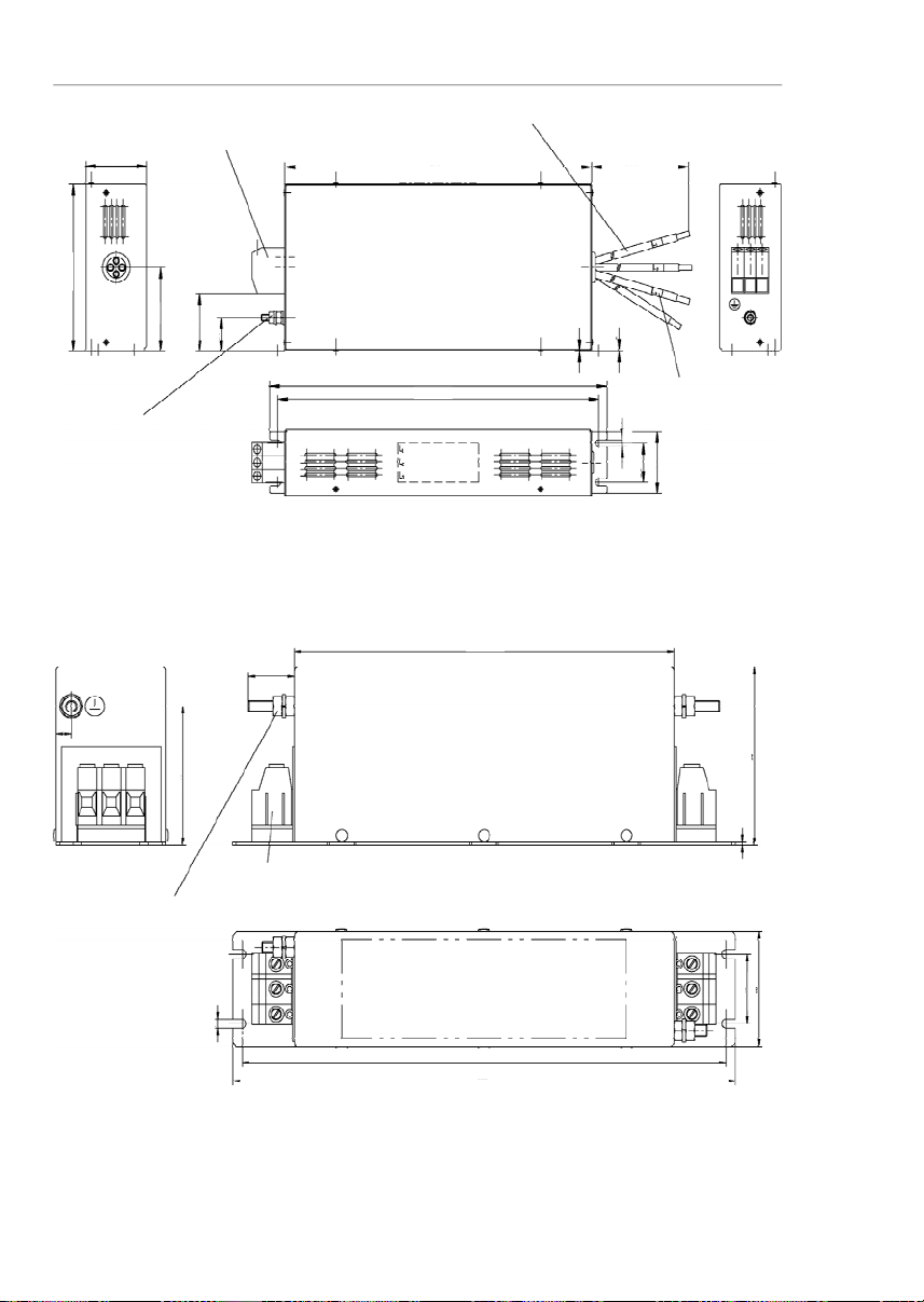
64
CHAPTER 3 - INSTALLATION
AND CONNECTION
Figure3.33
-External filterdrawing B84143-A50-R105
Terminals 10 mm
2
Tightening torque of screw 1,2 - 1,5 Nm
Earth connector M6
Tightening torque 4,8 ± 0,2 Nm
Marking
Note:
figure dimensions are in mm.
703558
255
265
200
90
1,5
4,5
24
8
Figure3.32
-External filterdrawing B84143-B50-R110
Terminals 16 mm
2
Tightening torque of screw 1,65 ± 0,15 Nm
Litz wire 10 mm
2
Earth connector M6x25
Tighteningtorque
4,8 ± 0,2 Nm
Marking
Note:
figure dimensions are in mm.
6,5
35±0,3
56601507530
(52)
330
315 ±0,5
300
500 ±10
0,5
1
Page 66

65
CHAPTER 3 - INSTALLATION
AND CONNECTION
Figure 3.34
- External filter drawingB84143-B8-R110
Terminals4 mm
2
Tightening torque of screw 0,7 ± 0,1 Nm
Litz wire 1,5 mm
2
Earth connector M6x25
Tightening torque 4,8 ± 0,2 Nm
Note:
figure dimensions are in mm.
Marking
Marking
50
80
40
(31)
15
230
215 ±0,5
200
300 ±10
0,5
6,5
25 ±0,3
46
Figure3.35
- External filter drawingB84143-B25-R110
Terminals6 mm
2
Tightening torque 1,5 - 1,8 Nm
PE M6x24
Tighteningtorque
3 ± 0,15 Nm
Litz wire 4 mm
2
Marking
Note:
figure dimensions are in mm.
Marking
Line
Load
15060756030
248
400 ±10
35 ±0,3
56
265 ±0,5
280
0,5
6,5
1
1
1
1
Page 67

66
CHAPTER 3 - INSTALLATION
AND CONNECTION
NOTE!
The declaration of conformity CE is available on the website
www.weg.netorontheCD,whichcomeswiththe products.
Figure3.36
-External filterdrawingB84143-G36-R110
Terminals6 mm
2
Tightening torque 1,5 - 1,8 Nm
PE M6x24
Tighteningtorque
3 ± 0,15 Nm
Litz wire 6 mm
2
Marking
Note:
figure dimensions are in mm.
Marking
Load
Line
15060756030
248
400 ±10
35 ±0,3
56
265 ±0,5
280
0,5
1
1
1
6,5
Page 68

67
KEYPAD(HMI)OPERATION
This chapter describes the standard Human Machine
Interface(HMI)oftheinverter(HMI-CFW08-P)andthemanner
touse it,presentingthe following information:
Generalkeypad description.
Useof the keypad.
Parameterprogrammingandreading.
Descriptionof thestatusindicationsand signalizations.
ThestandardCFW-08keypadhasa LEDdisplaywith4digits
of 7 segments, 4 status LEDs and 8 keys. Figure 4.1 shows
thefrontviewofthekeypadandindicatestheposition of the
displayandthestatusLEDs.
4.1
KEYPAD(HMI)
DESCRIPTION
LED Display
LED"Local"
LED"Remote"
LED"FWD"
LED "REV"
Figure 4.1
- CFW-08 standard keypad
Functions of the LED display:
TheLED displayshowsthefaultcodes anddrivestatus(refer
to Quick Parameter Reference, Fault Messages), the
parameternumber and its value.Theunit display(rightmost)
indicates the unit of some variables [U = volts,A=Ampères,
°C = Celsiusdegrees].
Functions of the “Local” and “Remote” LEDs:
InverterinLocalmode:
Green LED ON and red LED OFF.
InverterinRemote mode:
Green LED OFF and red LED ON.
Functions of the FWD/REV LEDs - Direction of rotation
Refertofigure4.2.
CHAPTER4
Page 69

68
CHAPTER 4 - KEYPAD (HMI) OPERATION
Figure 4.2
- Direction of rotation (FWD/REV) LEDs
OFFONFlashing
Basic functions of the keys:
Startstheinvertervia accelerationramp.
Stops(disables) the inverter via deceleration ramp.
Alsoresetsinverter after a fault has occurred.
TogglestheLED display between parameter number and its
value(number/value).
Increases the frequency, the parameter number or the
parametervalue.
Decreases the frequency, the parameter number or the
parametervalue.
Reverses the direction of motor rotation between Forward/
Reverse
Toggles between the LOCAL and REMOTE modes of
operation.
PerformstheJOGfunctionwhenpressed. AnyDIprogrammed
forGeneralEnable (ifany) mustbe closedtoenabletheJOG
function.
ThekeypadisusedforprogrammingandoperatingtheCFW-08,
allowingthefollowingfunctions:
Indicationof the inverterstatus and operationvariables.
Faultindicationand diagnostics.
Viewingandprogramming parameters.
4.2
USE OF THE
KEYPAD(HMI)
FWD/REV
Control
Selection
FWD / REV
HMILED
Situation
Forward
Reverse
Forward
ttt
Page 70

69
CHAPTER 4 - KEYPAD (HMI) OPERATION
4.2.1
KeypadOperation
All functions relating to the CFW-08 operation (Start/Stop,
Direction of Rotation, JOG, Increment/Decrement, Speed
(Frequency) Reference,andselectionofLocal/Remotemode)
canbe performedthroughthe HMIselection.
Forfactorydefaultprogrammingoftheinverter, allkeypadkeys
areenabledwhenthe Local mode has been selected.
Thesesame functions can be performed through digital and
analoginputs.Thusyoumustprogramtheparametersrelated
tothese correspondinginputs.
NOTE!
The control keys , and are only enabled if:
P229 = 0 for Local mode operation.
P230 = 0 for Remotemode operation.
The key depends of the parameters aboveand if:
P231 = 2.
Keypadkeysoperation description:
Whenenabled(P220= 2or 3),selectsthecontrolinputandthe
speed reference (speed)source, toggling betweenLocal
and
RemoteMode.
Whenpressed,startsthemotoraccordingtoaccelerationramp
uptothe speed (frequency)reference.The functionissimilar
to that performed through digital input Start/Stop, when it is
closed(enabled) and maintainedenabled.
Disables the inverter via deceleration ramp.The Function is
similartothatperformedthroughdigitalinputStart/Stop,when
it is open (disabled) and maintained disabled.
When the JOG key is pressed, it accelerates the motor
according to the acceleration ramp up to the JOG speed
programmed in P122.
This key is only enabled when the inverter digital input,
programmed to Start/Stop (if any) is open and the digital
inputprogrammedtoGeneralEnable(if any)isclosed.
When enabled, reversesthe motor directionofrotation.
Motorspeed (frequency) setting: these keysareenabled for
speedsetting onlywhen:
The speed reference source is the keypad (P221 = 0 for
Local Mode and/or P222 = 0 for Remote Mode).
Thefollowingparametercontent is displayed:P002,P005
or P121.
Operation of the inverter (keys , , , and
) and speed referencesetting (keys and ).
Page 71

70
CHAPTER 4 - KEYPAD (HMI) OPERATION
Inverteris Ready to be started.
Line voltage is too low for inverter
operation(undervoltage condition).
Inver
terisinafaultcondition.Faultcode
isflashingon thedisplay. In the example
there is the fault code E02 (refer to
chapter7).
Inverter is applying a DC current on the
motor (DC braking)
according to the
values programmed at P300, P301 and
P302 (refer to chapter 6).
Inverteris runningself-tuning routine to
identifymotorparametersautomatically.
This operation is controlled by P408
(refertochapter6).
COPYfunction(availableonlyattheHMI–
CFW08-RS), it copies the inverter
programmingintotheHMI.
COPYfunction(availableonlyattheHMI–
CFW08-RS),itcopiestheprogramming
fromtheHMIinto theinverter.
Inverterin theSleeprdymode.
NOTE!
The display also flashesin the followingconditions,besides
thefaultconditions:
Tryingtochangea parametervaluewhenit is not allowed.
Inverterin overloadcondition(refer to chapter7).
4.2.2
InverterStatus
ParameterP121storesthespeed
(frequency)
referencesetby
thekeys:
When pressed,it increasesthespeed(frequency)reference.
Whenpressed,it decreasesthespeed(frequency)reference.
Reference Backup:
The last frequency reference setbythe keys and
is
storedwhen inverter is stopped or theAC powerisremoved,
provided P120 = 1 (reference backup active is the
factory
default).To changethefrequencyreferencebeforestartingthe
inverter,thevalueoftheparameterP121mustbechanged.
Page 72

71
CHAPTER 4 - KEYPAD (HMI) OPERATION
4.2.4
Parameter Viewing and
Programming
All CFW-08 settings are made through parameters. The
parameter are shown on the display by the letter
P
followed
bya number:
Example(P101):
101 = Parameter Number
Each parameter is associated with a numerical value
(parameter value), that corresponds to the selected option
amongtheavailableonesforthisparameter.
Theparametervalues definethe inverterprogrammingor the
value of a variable (e.g.: current, frequency,voltage).For in-
verter programming you should change the parameter
content(s).
Itisnecessaryto set P000 =5 before to change a parameter
value.Otherwiseyoucanonlyreadtheparametervalues,but
notreprogram them
.
Formoredetails,refer to the parameter
P000 description inchapter 6.
ACTION
HMIDISPLAY
DESCRIPTION
TurnON the inverter
Press the key
Use the keys
and
Press the key
Use the keys
and
Press the key
Inverteris ready to be started
Select thedesired parameter
Numericalvalue associated with the
parameter
(4)
Set the new desired value
(1) (4)
(1) (2) (3)
ParametersP002toP099arereservedforthedisplayofread-
onlyvalues.
Thefactorydefaultdisplaywhenpowerisappliedtotheinverter
is P002 (frequency proportional value in V/F control mode
(P202=0or1)andmotorspeedinrpm in vectorcontrolmode
(P202 = 2)).
ParameterP205definesthe initialmonitoringparameter, i.e.,
definesthe read-onlyvariable thatwillbe displayedwhenthe
inverter is powered up. For further information refer to P205
descriptionin chapter 6.
4.2.3
Read-OnlyParameters
Page 73

72
CHAPTER 4 - KEYPAD (HMI) OPERATION
(3)
If the last programmed value in the parameter is not
functionallycompatiblewithotherparametervaluesalready
programmed,E24 =ProgrammingError, willbe displayed.
Exampleof programmingerror:
Programming of two digital inputs (DI) with the same
function. Refer to table 4.1 for list of programming errors
thatcan generatean E24 Programming Error.
(4)
Toallowthereprogrammingofanyparametervalue(except
for P000 and P121) it is required to set P000 = 5.
Otherwiseyoucan onlyreadtheparametervalues,butnot
reprogram them
.
Formoredetails, refer to the parameter
P000 description inchapter 6.
NOTE!
(1)
Forparametersthatcanbechangedwiththemotorrunning,
theinverter willusethenew value immediatelyafter it has
been set. For parameters that can be changed only with
motorstopped,theinverterwillusethisnewvalueonlyafter
the key is pressed.
(2)
By pressing the key after the reprogramming, the
new programmed value will be stored automatically and
willremainstored until a new value is programmed.
Page 74

73
CHAPTER 4 - KEYPAD (HMI) OPERATION
NOTE!
It is possible that during programming occurs the error E24
causedby incompatibilitybetweensome parametersalready
programmed.
In this case do not stop with the parameter setting. If at the
end of the parameter setting does not disappear, check the
tableof incompatibilities (table4.1).
Table 4.1
- Incompatibility of parameters - E24
JOG
P265=3 and other(s) DI(s)
Start-Stop or FWD and REV or ON and OFF
P266=3 and other(s) DI(s)
Start-Stop or FWD and REV or ON and OFF
P267=3 and other(s) DI(s)
Start-Stop or FWD and REV or ON and OFF
P268=3 and other(s) DI(s)
Start-Stop
or FWD and REV or ON and OFF
Local/Remote
Two or more parameters between P264, P265, P266, P267 and P268 equal to 1
(LOC/REM)
Disables Flying
Start
P265=13 and P266
=
13or
P267=13 or
P268=13
Reset
P265=10 and
P266=
10or
P267=10 or
P268=10On/Off
P263=14 and
P2
6414 or
P26314 and
P264=14Direction of
R
otation
Two or more parameters P264, P265, P266, P267 and P268 = 0 (
D
irection of
R
otation)
FWD/REV
P263=8 and P264
8 and P264
13
P263=13 and P264
8 and P264
13
P2638 and P263
13 and P264
=8P263=8 or 13 and P264
=
8 or 13 and P265
=
0 or P266
=
0 or P267
=
0 or P268
=0P263=8 or 13 and P264
=
8 or 13 and P231
2
Multispeed
P221=6 or P222
=
6 and P264
7 and P265
7 and P266
7 and P267
7 and P268
7
P2216 and P222
6 and P264
=
7 or P265
=
7 or P266
=
7 or P267
=
7 and P268
=7Electronic
Potentiometer
P221 = 4 or P222 = 4 and P265
5 or 16 and P266
5 or 16 and P267
5 or 16 and
P2685 or 16
P2214 or P222
4 and P265 = 5 or 16 or
P266 = 5 or16 or P267 = 5 or 16 or
P268 = 5 or 16
P265=5 or 16 and P266
5 or 16 and P268
5 or 16
P266=5 or 16 and P265
5 or 16 and P267
5 or 16
P267=5 or 16 and P266
5 or 16 and P268
5 or 16
P268=5 or 16 and P265
5 or 16 and P267
5 or 16
RatedCurrent
P295 incompatible with the inverter model
DC Braking and
Ride-through
P3000 and P310 = 2 or 3
PID
P203=1 and P221
=
1,4,5,6,7 or 8 or P222
=
1,4,5,6,7 or 8
Ramp 2
P265=6 and P266
=
6 or P265
=
6 and P267
=
6 or P265
=6and P268
=6P266=6 and P267
=
6 or P267
=
6 and P268
=
6 or P266
=
6 and P268
=6P265=6 or P266
=
6 or P267
=
6 or P268
=
6 and P263
=13P265=6 or P266
=
6 or P267
=
6 or P268
=
6 and P264
=13P265=6 or P266
=
6 or P267
=
6 or P268
=
6 and P2
63=13
P265=6 or P266
=
6 or P267
=
6 or P268
=
6 and P264
=13Model
P221=2,3,7 or 8 and standard inverter
P221=2,3,7 or 8 and standard inverter
Analog
Input
P221=1 or P222
=
1 and P235
=
2, 3, 4 or 5
P221 or P222
=
2 or 3 and P239
=
2, 3, 4
or 5
Programming Error – E24
Page 75

74
5.1
PRE-POWER
CHECKS
Thischapterprovidesthe followinginformation:
Howto check andpreparetheinverterbefore power-up.
Howtopower-upandcheckfor proper operation.
How to operate the inverter when it is installed according
to the typical connections (refer to item 3.2 - Electrical
Installation).
The inverter shall be installed according to Chapter 3 -
InstallationandConnection.Ifthedriveprojectisdifferentfrom
the typical suggested connections, follow the procedures
below.
DANGER!
Always disconnect the AC input power before making any
connections.
1)
Check all connections
Checkif the power,groundingandcontrol connectionsare
correctand welltightened.
2)
Check the motor
Check all motor connections and verify if its voltage and
currentmatchthe inverterspecifications.
3)
Uncouple the load from the motor
If the motor can not be uncoupled, make sure that the
directionof rotation(FWD/REV)cannotcause damage to
themachine.
Afterthe inverterhasbeenchecked,ACpowercanbeapplied:
1)
Check the power supply
Measurethe linevoltage and check if it is withinthe
specified range (ratedvoltage: -15 % / +10 %).
2)
Power-up the AC input
Closethe input circuit breakeror disconnect switch.
3)
Check if the power-up has been successful
-Inverterwithkeypad(HMI-CFW08-PorHMI-CFW08-RS)or
HMI-CFW08-RP
Thekeypaddisplay willshow:
5.2
INITIAL
POWER-UP
START-UP
CHAPTER 5
Page 76

75
CHAPTER 5 - START-UP
5.3
START-UP
This section describes start-up procedures when operating
viathe keypad(HMI).Twotypesof controlwillbe considered:
V/F and Vector Control:
TheV/Fcontrolisrecommendedinthefollowingcases:
Severalmotors driven bythe same inverter.
Ratedcurrentofthemotorislowerthan1/3ofratedinverter
current.
Fortestpurposes,inverterisstart-upwithout load.
The V/F control can also be used in applications that do not
requirefastdynamicresponses,accurate speed regulations
or high starting torque (speed error will be a function of the
motor slip); when you program parameter P138 - Slip
Compensation - you can obtaina speed accuracy of 1 %.
Forthe most applications, we recommend thevector
control
mode, that permits a higher speed control accuracy (typical
0.5%),
higherstarting
torque
anda fasterdynamicresponse.
The necessary adjustments for the operation of the vector
controlareperformedautomatically.Inthiscasethemotorshall
beconnectedto theCFW-08.
This means that the inverter is ready (rdy = ready) to be
operated.
- Inverter with dummy panel (TCL-CFW08 or TCR-
CFW08).
TheLEDsON (green)andERROR (red) areON.
Inverterruns someself-diagnosisroutines.Ifno problemsare
found the LED ERROR (red) turns OFF.This means that the
inverteris now ready to be operated.
ThefourLEDsofthekeypadremainsONduringthisprocedure.
Inverterruns someself-diagnosisroutines.Ifno problemsare
found,the displayshows:
DANGER!
EvenaftertheAC powersupplyhasbeendisconnected,high
voltages may be still present.
Wait at least
10 minut
esafter
poweringdown to allow full discharge of thecapacitors.
Page 77

76
CHAPTER 5 - START-UP
NOTE!
Thelastfrequencyreference(speed)valuesetviathe
and keys is saved.
Ifyouwishtochangethisvaluebeforeinverterenabling,change
parameterP121-KeypadReference.
NOTES!
(1)
Ifthedirectionofrotationofthemotorisnotcorrect,switchoff
theinverter. Wait at least for 10 minutesto allowcomplete
capacitordischargeandthenswapanytwowiresatthemo-
toroutput.
(2)
Iftheaccelerationcurrentbecomes too high,mainlyatlow
frequencies,setthetorqueboost(IxRcompensation)atP136.
Increase/decrease the contentof P136 gradually until you
obtain an operation with constant current over the entire
frequencyrange.
Forthecaseabove,refertoparameterdescriptioninchapter
6.
(3)
If E01 fault occurs during deceleration, increase the
decelerationtimeatP101/ P103.
ACTION
HMIDISPLAY
DESCRIPTION
Power-upthe inverter
Press the key
Press the keyand hold it
depressed until 60 Hz is reached
Press the key
Press
the key
Press
the
key and hold it
depressed
Release the key
Inverteris readyto be operated
Motoracceleratesfrom 0 Hzto 3 Hz
(*)
(
minimum
frequency), intheforward(CW)
directionofrotation
(1)
Motor accelerates up to 60 Hz
(**)
(2)
Motordecelerates
(3)
downto 0 rpm and
then reverses the direction of rotation
CWCCW accelerating back to 60Hz
Motordecelerates down to 0 rpm
Motoraccelerates up to JOG frequency
given by P122.
Ex:
P122 = 5.00 Hz
Reverse(CCW)
Motordecelerates down to 0 rpm
5.3.1
Start-up-
Operationvia Keypad
(HMI)-Typeof Control:
Linear V/F (P202 = 0)
Thesequencebelowisvalidfortheconnection1 (referto item
3.2.6). Inverter must be already installed and powered up
according to chapter 3 and item 5.2.
Connectionsaccordingtofigure3.6.
(*)
90rpmfor4 pole motor.
(**)
1800 rpm for 4 pole motor.
Page 78

77
CHAPTER 5 - START-UP
5.3.2
Start-up-
Operationvia Terminals-
ControlMode:
Linear V/F (P202 = 0)
Connections are according to figures3.6and 3.16.
ACTION
HMIDISPLAY
DESCRIPTION
Referto figure3.16
Switch
S1(
FWD / REV
)=open
Switch S2 (Reset) = open
Switch S3 (Start/Stop)= open
Poten
tiometer
R1(Ref.)
=
totallyCCW
Power-upinverter
Press the key.
This procedure isnot necessarywhen
invertersweredelivereddummypanel,
sinceit will be automatically in remote
mode
CloseS3– Start/Stop
Turnpotentiometer totallyCW
CloseS1– FWD / REV
OpenS3– Start / Stop
Inverteris readyto be operated
L
ocal LED
switches OFF and remote
LED switches ON
.
Control and
Referenceare switchedto remote
(via
terminals
)
Note:
Tomaintaininverterpermanently
in remote mode, set
P220=1.
Ifthe inverter is switched offand
afterwardsswitched on, it
will
nowoperate in local mode
because P220 = 2 (factory
setting). This setting means
that the local/remote selection
source is via keypad and the
default mode (that is the mode
whenthe inverter is switched
on) is local. For further
informationrefer to the
description of P220 in chapter 6
Motor accelerates from 0 Hz to 3 Hz
(*)
(minimum frequency), CW direction
(1)
Thefrequency referenceis given bythe
potentiometerR1
Motor accelerates up to the maximum
frequency(P134 = 66 Hz)
(2)
Motor decelerates
(3)
down to 0 rpm (0
Hz),reverses the direction of rotation
(FWD/REV)acceleratingback up tothe
maximumfrequency(P134= 66 Hz)
Motor decelerates
(3)
down to 0 rpm
NOTES!
(1)
Ifthe directionof rotationof themotorisnotcorrect,switch
off the inverter. Wait 10 minutes to allow a complete
capacitor discharge and swap any two wires at the motor
output
.
(2)
Ifthe accelerationcurrentbecomestoohigh,mainlyat low
frequencies, set the torque boost (IxR Compensation) at
P136.
(*)
90rpmfor4-pole motor.
Page 79

78
CHAPTER 5 - START-UP
5.3.3
Start-up-
Operationvia Keypad -
ControlMode:
Vector(P202 = 2)
ACTION
HMIDISPLAY
DESCRIPTION
Power-upinverter
Press key. Press the
key until P000
is reached. You can
also use the key to reach
theparamater P000
Press the keyto enter into
the
parameterP000
programming
mode
Use the keys and to
set the passoword value
(P000 = 5)
Press the key to save the
selected option and to exit the
programmingmode
Press the key or until
P202
is reached
Press the key to enter into
the
parameterP202.
programming
mode
Inverteris readyto be operated
P000= accessfor changingparameters
Enterthe programmingmode
P000 = 5: permits parameter changing
Exit the programming mode
This parameter definesthe control type
0 = V/F Linear
1 = V/F Quadratic
2 = Vector
Enterthe programmingmode
Increase/decreasethecontentofP136graduallyuntilyou
obtain an operation with constant current over the entire
frequencyrange.
For the case above, refer to parameter description in
chapter6.
(3)
If E01 fault occurs during deceleration, increase the
deceleration time at P101 / P103.
The sequence below is based on the following inverter and
motorexample:
Inverter:
CFW080040S2024ESZ
Motor:
WEG-IP55
Power:0.75 HP/0.55 kW;
Framesize:71; RPM: 1720; Number of Poles:IV;
Power Factor (cos
): 0.70;
Efficiency (
):71%;
Rated Current at 220 V:2.90A;
Frequency:60 Hz.
Page 80

79
CHAPTER 5 - START-UP
ACTION
HMIDISPLAY
DESCRIPTION
Use the and keys
to select the control type
Press
to save the selected
option and to start the tuning routine
afterchangingtoVectorControlmode
Press the key and use the
keys and to set the
correct rated motor efficiency
(inthis case
71%)Press the key to save the
selected option and to exit the
programmingmode
Press the key to go to the
nextparameter
Press the key and use the
keys and to set the
correctrated motorvoltage
Press the key to save the
selected option and to exit the
programmingmode
Press the key to go to the
nextparameter
Press the key and use the
keys and to set the
correct rated motor current (in this
case 2.90 A)
Press keyto save the
selected option and to exit the
programmingmode
Press the to go to the next
parameter
Press the key and use the
keys and to set the
correct motor speed (in this case
1720rpm)
Press the key to save the
selected option and exit the
programmingmode
Press the key to go to the
next parameter
P202 = 2: Vector
Motor efficiency:
50 to 99.9 %
Set motor efficiency:
71 %
Exit the programming mode
Ratedmotorvoltage range:
0 to 600 V
Setrated motor voltage:
220V(thedefault valueismaintained)
(2)
Exit the programming mode
Ratedmotor currentrange:
0.3 x I
nom
to 1.3 x I
nom
Set rated motor current: 2.90 A
Exit the programming mode
Ratedmotor rpm range:
0 to 9999 rpm
Programmedrated motorrpm:
1720rpm
Exit the programming mode
Ratedmotor frequency:
0 to F
max
Page 81

80
CHAPTER 5 - START-UP
ACTION
HMIDISPLAY
DESCRIPTION
Press
and use the keys
and
to set the correct
valuefor themotor frequency
Press the key to save the
selected option and exit the
programmingmode
Press the key to go to the
nextparameter
Press the keyand use the
keys and to set the
correctmotor power
Press the key to save the
selected option and exit the
programmingmode
Press the key to go to the
nextparameter
Press the key and use the
keys and to set the
correct motor power factor (in this
case 0.70)
Press the key to save the
selected option and exit the
programmingmode
Press the key to go to the
nextparameter
Press the key and use the
keys and to authorize or
not the start of the parameter
estimate
Press the keyto start the
self-tuningroutine. While the self-
tuning routine is running, the display
shows "Auto”
Therunningof theSelf-Tuning
Routine can last until 2 minutes and
after ending displaywill show “rdy”
(ready),whenthe motor parameter
were acquired with success.
Otherwise the fault “E14” is shown.
In this case refer to note
(1)
below
Set rated motor frequency:
60Hz(thedefault valueis maintained)
(2)
Exit the programming mode
Ratedmotor powerrange:
0 to15 (each value represents a power
value)
Selected rated motor power:
4 = 0.75 HP / 0.55 kW
Exit the programming mode
Motorpowerfactor range:
0.5 to 0.99
Set motor powerfactor:
0.70
Exit the programming mode
Parameterestimation?
0 = No
1 = Yes
1 = Yes
Self-tuningis running
Inverterfinishedtheself-tuningroutine
and is readyfor operation,
or
Runningof self-tuning routine has not
been realized with success
(1)
or
Page 82

81
CHAPTER 5 - START-UP
NOTE!
The last speed reference value set via key and
keys
is saved.
Ifyou wishto changethis valuebeforeenablingofinverter,
change the value of the parameter P121 - Keypad
Reference.
Theself-tuning routinecanbe cancelledbypressingthe
key.
NOTES!
(1)
Ifduringtherunningof theSelf-Tuning Routinethedisplay
showsE14,
this means that the motor parameters were
not acquired correctly by the inverter.The most common
reason for this fault maybe that the motor has not been
coupled to the inverter output. However motors withvery
lower currents than the used inverter, or incorrect motor
connection may also cause the fault E14. In this case,
operate the inverter in V/F mode (P202 = 0). When the
motor is not connected and the fault condition
E14isindicated,proceed as follows:
Switchoff theinverter. Wait at least10minutesto allow
a complete discharge of the capacitors.
Connectthe motorto the inverteroutput.
ACTION
HMIDISPLAY
DESCRIPTION
Press the key
Press the key and hold it
depressed until the speed of
1980rpm is reached
Press
the key
Press the
key
Press the key and hold it
depressed
Release the key
Motor accelerates up to 90 rpm (for IV
pole motor - minimum speed) in CW
direction of rotation
(3)
Motoraccelerates up to 1980 rpm (for
IV pole motor - maximum speed)
Motor decelerates
(4)
to 0 rpm and
thenreverses the directionof rotation
CWCCW,
accelerating back to
1980rpm
Motordecelerates down to 0 rpm
Motor accelerates from 0 rpm up to the
JOG speed set at P122
Ex:
P122 = 5.00 Hz that corresponds
to 150 rpm for IV-polemotor
Reverse(CCW) directionofrotation
Motordecelerates down to 0 rpm
Page 83

82
CHAPTER 5 - START-UP
Switchontheinverter.
Set P000 = 5 and P408 = 1.
Follow from now on the start-up procedures described
initem 5.3.3.
(2)
For each inverter type, the parameters P399 to P407 are
setautomatically
tothe rated motor data, considering a
standardWEGmotor,IVpoles,60Hz.
When different motors are used, you must set the
parameters manually,according to the motor nameplate
data.
(3)
Ifthedirectionofrotationofthemotorisnotcorrect, switch
offthe inverter. Wait atleast10minutestoallowa comple-
tedischargeofthecapacitorsandthenswapanytwowires
atthe motoroutput.
(4)
Iffault E01 occursduringdeceleration,you mustincrease
thedeceleration time at P101/P103.
Page 84

83
CHAPTER6
6.1
SYMBOLS
DETAILEDPARAMETERDESCRIPTION
This chapter describes in detail all CFW-08 parameters and
functions.
Some symbols used in this chapter are presentedbelow:
AIx
=Analog inputnumber x.
AO
=Analogoutput.
DIx
=Digital input numberx.
F*
= Frequency reference. This is the frequency value that
indicatesthedesired motorspeedatthe inverter output.
Fe=Inputfrequencyoftheaccelerationanddecelerationramp.
F
max
=Maximumoutputfrequency, defined at P134.
F
min
=Minimumoutputfrequency,defined at P133.
Fs=Outputfrequency- frequencyappliedto the motor.
I
nom
=Ratedinverteroutputcurrent(rms),inAmpères(A).This
valueis defined inP295.
Is=Inverteroutputcurrent.
Ia=Activecurrentat inverteroutput,i.e.,it isthecomponentof
the total motor current proportional to active electric power
absorbedbythemotor.
RLx
=Relayoutputnumberx.
Ud= DC link voltage in the DC link circuit.
This section describes the main concepts related to the
CFW-08
frequencyinverter.
As already informed in
item
2.3, CFW-08 has in the same
producta V/Fcontrol and a sensorlessvector control(VVC:
“voltage vector control”).
The user must choose one of them. Please find below a
description of each control mode.
This control mode is based on the constant V/F curve
(P202= 0 - linear V/Fcurve).Itsperformanceislimitedat low
frequencies as function of the voltage drop in the stator
resistance,that causes a significant magnetic flow reduction
in the motor air gap and consequently reducing the motor
torque. This deficiency should be compensated by using
manualandautomaticboosttorque(IxRcompensations),that
are set according to the parameters P136 or P137.
Inmostapplications(forinstance:centrifugalpumpsandfans)
thesetting ofthesefunctionsisenoughto obtain therequired
performance. But there
areapplicationsthat require a more
sophisticatedcontrol.Inthesecases
it'srecommendedtheuse
of the sensorless vector control, that will be describedin the
item 6.2.3 - VectorControl(VVC).
6.2
INTRODUCTION
6.2.2
V/FControl
6.2.1
ControlModes
(V/F and Vector)
Page 85

84
CHAPTER 6 - DETAILED PARAMETER DESCRIPTION
6.2.3
VectorControl (VVC)
InV/F control, the speed regulation, that can be obtained by
settingproperlyslip compensationcan be maintained within
1 % to 2 % of the rated speed. For instance, for a IV pole
motor/60Hz,theminimumspeedvariationatnoloadcondition
andat rated loadcanbemaintainedbetween18 and 36 rpm.
Thereis still avariationof thelinearV/F control:the quadratic
V/Fcontrol.Thiscontrolmode is suitableforapplicationslike
centrifugal pumps and fans (loads with quadratic torque x
speedcharacteristics),sinceitenablesa motorlossreduction,
resultingin an additional energysaving by using an inverter.
Formore details about the V/F control mode, please referto
the description of the parameters P136, P137, P138, P142
and P145.
Inthe sensorless vectorcontrol availableattheCFW-08,the
inverter operation is optimized for the used motor, so that a
better performance in terms of torque and speed regulation
is obtained. This vector control does not require a signal of
the speed feedback through tachogenerator or encoder
coupledon motorshaft.
To maintain the magnetic flux in the motor air gap constant,
and consequently the motor torque, within the whole speed
variationrange(fromzerouptothefield weakening point),a
sophisticated control algorithm is used that considers the
mathematicmodel of the inductionmotor.
Thusone canmaintainthe magnetic flux in the motor air gap
approximatelyconstantatfrequenciesdowntoapproximately
1Hz.
In vector control mode one can obtain a speed regulation of
0.5% (relatingtotheratedspeed).Thus,for instance,foraIV
polemotor/60Hzonecan obtainaspeedvariationin the ran-
ge of 10 rpm.
Other advantage of the vector control is its easy setting
procedure. The user needs only to enter in the parameters
P399 and P407 the information about the used motor
(nameplatedata)andruns theself-tuning routine (bysetting
P408 = 1) and the inverter configures itself to the required
application. So the inverter is ready to be operated in an
optimizedmanner.
Formoreinformation,refertothedescriptionofthe parameters
P178 and P399 to P409.
Page 86

85
CHAPTER 6 - DETAILED PARAMETER DESCRIPTION
Thefrequencyreference(i.e.,thedesiredoutputfrequency,or
alternatively,themotorspeed)canbedefinedinseveralways:
Thekeypad-digitalreference thatcanbechangedthrough
thekeypad(HMI),by using the keys
and
(refer
to the parameters P221, P222and P121);
Analog input - the analog input AI1 (XC1:6) or the AI2
(XC1:8) canbeused,orboth(refertotheparametersP221,
P222 and P234 to P240);
Multispeed- up to 8 presetdigital references (refer to the
parameters P221, P222 and P124 to P131);
Electronic potentiometer (EP) - another digital reference,
itsvalueisdefinedby using 2 digital inputs (DI3 and DI4) -
refer to the parameters P221, P222, P265 and 266;
Via serial.
Figure 6.1 shows through a diagram block the frequency
referencedefinition tobeused by the inverter.
Theblockdiagraminfigure 6.2 shows the invertercontrol.
NOTE!
AI2isonlyavailable in CFW-08Plusversion.
DIsON when connectedto0V (XC1:5)withS1:1 OFF and
whenconnected to 24 V(external)with S1:1 to ON.
When F* < 0 one takes the module of F*and reverses the
directionof rotation
(
if this is possible
-P231
=2andif the
selectedcontrolisnot forwardrun/reverserun).
6.2.4
FrequencyReference
Sources
Page 87

86
CHAPTER 6 - DETAILED PARAMETER DESCRIPTION
Figure 6.1
- Block diagram of the frequency reference
RS-232
PCandCLP
KEYPAD
REFERENCE
(P121)
HMI-CFW08-RPor
HMI-CFW08-RS
KCS-CFW08
P124to P131
P264 = 7
P265 = 7
P266 = 7
MULTISPEED
Accel.
EnablingFunction
P265 = 5
P266 = 5
Decel.
Inverter
Disabled
ELECTRONICPOTENTIOMETER(EP)
AI2
AI1
DI4
DI3
DI2123456789101112
XC1
AI1
P235
AI2
P239
P238
P134
P234
P134
P236
P240
2 or 3 - AI2
7 - Add AI>0
8 - Add AI
1 - AI1
4- EP
6 - Multispeed
5 - Serial or
CANopen or
DeviceNet
0 - Keypad
Frequency Reference
Selection
P221 or P222
F*
Digital
References
Analog
References
P131
P130
P129
P128
P127
P126
P125
P124
000 001 010 0 11 100 101 110 1 11
100%
P239=0
P239=102V/ 4mA
10V/ 20m A
100%
P235=0
P235=102V/ 4mA
10V/ 20m A
0 V
Reset
HMI-CFW08-P
RS-485
KRS-485
KFB-COorKFB-DN
CANopen
or
DeviceNet
Page 88

87
CHAPTER 6 - DETAILED PARAMETER DESCRIPTION
Fe
Commandvia
DigitalInput
(DI)
Acceleration
and
Deceleration
Ramp2
Acceleration and
DecelerationRamp
P102
P103
P100
P101
DCLink
Regulation
P151
P151
U
d
P133
P134
Frequency
Reference
Limits
P202
P295
Inverter
Control
(V/F or
Vector)
P136,
P137,P138,
P142,P145
Motor
Parameters
(P399 to P409)
P178
V
s
PWM
P169
IsP169
IsOutput Current
Limiting
I
V
s
UdPower
Supply
IM
3Ø
I
s
NOTE!
InV/F control mode(P202= 0or1), Fe = F* (refer tofigure
6.1)if P138 = 0 (slip compensation disabled).IfP138
0,
referto figure 6.9 for the relationbetweenFe and F*.
Invectorcontrol mode (P202 = 2) always Fe = F* (refer to
figure6.1).
Figure 6.2
- Block diagram of the inverter control
Page 89

88
CHAPTER 6 - DETAILED PARAMETER DESCRIPTION
6.2.5
Commands
6.2.6
Local/Remote
OperationModes
Theinverterhasthefollowingcommands:PWMpulseenabling/
disabling,definition of the direction of rotation and JOG.
As the frequency reference, the inverter commands can de
definedinseveralways.
Thecommand sources arethefollowing:
Via keypad - keys , , and .
Via control terminals (XC1) - digital inputs.
Via serial interface.
Theinverterenablinganddisablingcommandscanbedefined
asfollows:
Via keypad and of the HMI.
Via serial.
Start/stop (terminals XC1 - DI(s) - refer to the parameter
P263 to P266).
General enable (terminals XC1 - DI(s) - refer to the
parameter P263 to P266).
Forwardrun (terminalsXC1- DI(s) - refer to the parameter
P263 and P264), it also defines the diretion of rotation.
ON/OFF(3-wire control) (terminals XC1 - DIs - refer to the
parameters P263 and P264).
The definition of the direction of rotation can be defined by
using:
The key of the keypad.
Serial.
Digital input
(DI) program
med for FWD/REV
(
refer to the
parameter
P264 to P266)
.
DigitalinputsprogrammedasFWD / REV,thatdefinesboth
Inverterenablingor disablinganddirectionofrotation(refer
tothe parameters
P263 and P264).
Analoginput - whenthe referenceis via analog inputand a
negative offset is programmed (P236 or P240<0), the
referencemayassumenegativevalues,thus reversingthe
directionof the motorrotation.
User can define two different conditions relating to the
frequencyreferencesourceandtheinvertercommands:these
arethelocal and the remote operation modes.
Figure 6.3 shows the local and remote operation modes in a
block diagram.
With the factory setting in local mode the inverter can be
controlled by using the keypad, while in remote mode all
controls are via terminals (XC1) - reference definition and
invertercommands.
Page 90

89
CHAPTER 6 - DETAILED PARAMETER DESCRIPTION
Figure 6.3
- Block diagram of the local and remote operation mode
LOCAL
Frequency
Reference
P221
Controls
P229
(stop/run,
FWD/REV
andJOG)
0
Keypad
(HMI-CFW08-P,
HMI
-CFW08-RPand
HMI-CFW08-RS)
1
AI1
2
or 3 AI2
4EP5
Serial6Multispeed
7
AddAI
8
Add AI > 0
0
Keypad(HMI-
CFW08-Pand HMI-
CFW08-RP)
1
Terminals
XC1(DIs)
2
Serialor HMI-
CFW08-RSkeypad
REMOTE
Frequency
Reference
P222
Controls
P230
(stop/run,
FWD/REV
andJOG)
F*REFERENCE
COMMANDS
Local/RemoteSelection (P220)
+
Local/RemoteCommand
( , DI, Serial, etc)
6.3
PARAMETER
LISTING
Inorderto simplifytheexplanation,theparametershavebeen
groupedby characteristicsand functions:
Variables that can be viewed on the
display, but can not be changed by the
user
Programmable values used by the
CFW-08 functions
Theydefinethe invertercharacteristics,
the functions to be executed,as well as
the input/outputfunctions of the control
board
Data about the applied motor: data
indicated on the motor nameplate and
thoseobtainedduringthe runningof the
self-tuningroutine
Hereareincludedparametersrelatedto
special functions
0
Keypad
(HMI
-CFW08-P,
HMI-CFW08-RPand
HMI-
CFW08-RS)
1
AI1
2
or 3 AI2
4EP5
Serial6Multispeed
7
AddAI
8
AddAI>0
0
Keypad
(HMI-CFW-08-Pand
HMI- CFW-08-RP)
1
Terminals
XC1(DIs)
2
Serialor HMI-
CFW08-RSkeypad
Read-onlyParameters
RegulationParameters
ConfigurationParameters
MotorParameters
SpecialFunction Parameters
Page 91

90
CHAPTER 6 - DETAILED PARAMETER DESCRIPTION
Range
[Factory Setting]
Parameter
Unit
Description / Notes
P000
0 to 999
Parameter
[ 0 ]
Access
1
6.3.1
Access and Read-only Parameters - P000 to P099
P002
0 to 6553
Frequency
[- ]
Proportional
0.01 (99.99);
Value
0.1 (100.0);
1 (1000)
P003
0to1.5 x I
nom
MotorOutput
[- ]
Current
0.01A (
9.99A);
0.1A (
10.0A)
P004
0 to 862
DC Link Voltage
[- ]1V
Releasestheaccessto change the parameter values.
The password is 5.
Theuse of the passwordis alwaysactive.
Indicatesthevalue of P208 x P005.
When thevectorcontrolmode is used (P202= 2),P002
indicatesthe actual motor speed in rpm.
Incase of different scales and units, use P208.
IndicatestheinverteroutputcurrentinAmps (A).
Indicatesthe actual DC link voltage,involts(V).
P005
0
.00to300.0Motor
Output
[- ]
Frequency
0.01Hz
(99.99 Hz);
0.1Hz(
100.0Hz)
Indicatesthe inverteroutputfrequencyinHertz(Hz).
P007
0 to 600
MotorOutput
[- ]
Voltage
1 V
Indicatestheinverteroutputrms voltage,in volts (V).
Following notes may appear in some parameters during the
detailed description:
(1)
Thisparameterisonlydisplayedinvectormode(P202=2).
(2)
Thisparameteris onlydisplayedin
scalar mode P202 = 0
or 1.
(3)
Thisparameter can be changed only when the inverter is
disabled (stopped motor).
(4)
Thisparameteris onlyavailable withHMI-CFW08-RS.
(5)
The analog input value is represented by zero when it is
notconnectedtoanexternalsignal.Inordertouseananalog
inputasadigitalinputwithNPNlogic(P235orP239 =3),
itisnecessaryto connecta 10 k
resistorfrom terminal 7
to6(AI1)or8(AI2)of thecontrol terminal strip.
(6)
This parameter is only available in the CFW-08 Plus
version.
(7)
TheparametervaluechangesautomaticallywhenP203=1.
Page 92

91
CHAPTER 6 - DETAILED PARAMETER DESCRIPTION
P008
25 to 110
Heatsink
[- ]
Temperature
1oC
Indicates the current power at the heatsink in Celsius
degrees (°C).
Theinverterovertemperatureprotection(E04)actswhen
heatsinktemperaturereaches:
P009
(1)
0.0 to 150.0
MotorTorque
[- ]
0.1 %
Indicates the torque developed by motorin percent (%)
relatingtothesetratedmotortorque.
The rated motor torque is defined by the parameters
P402(ratedmotorspeed)andP404(ratedmotorpower).
I.e.:
Range
[Factory Setting]
Parameter
Unit
Description / Notes
Table6.1
- Temperature to act the overtemperatureprotection
P023
x.yz
SoftwareVersion
[- ]-P040
0 to 6553
PID Process
[- ]
Variable
1
(Value% x P528)
Indicates the software version installed in the DSP
memorylocated on the controlboard.
Parameter
P040,P203,P520
to
P528
are only available
fromthesoftwareversion V3.50 on.
Indica
testhe value of the process variable
u
sed as PID
feedback,inpercent(%).
The PID function is only available from the software
version V3.50on.
Theindicationunit can be changed throughP528.
Refertodetailed description of thePIDregulatorin item
6.3.5- Special Function Parameters.
whereT
nom
isgiveninkgf.m,P
nom
istheratedmotorpower
inwatts- HP -(P404),andn
nom
istheratedmotorspeed
in rpm - P402.
P014
00 to 41
LastFault
[- ]-Indicatesthe code of thelastoccuredfault.
Item
7.1
showsalistofpossiblefaults
,
theircodenumbers
andpossible causes.
T
nom
= 716 .
P
nomnnom
Inverter
1.6-2.6-4.0-7.0A/200-240V
1.0-1.6-2.6-4.0A/380-480V
7.3-10-16A/200-240V
2.7-4.3-6.5-10A/380-480V
13-16A/380-480V
22-28-33A/200-240V
24-30A/380-480V
P008 in ºC (ºF) @ E04
103(217.4)
90(194)
90(194)
103(217.4)
108(226.4)
104(219.2)
104(219.2)
Page 93

92
CHAPTER 6 - DETAILED PARAMETER DESCRIPTION
Range
[Factory Setting]
Parameter
Unit
Description / Notes
0.1 to 999
[ 5.0 s ]
0.1s (99.9 s);
1s (100 s)
0.1 to 999
[ 10.0 s ]
0.1s (99.9 s);
1s (100 s)
0.1 to 999
[ 5.0 s ]
0.1s (99.9 s);
1s (100 s)
0.1 to 999
[ 10.0 s ]
0.1s (99.9 s);
1s (100 s)
This set of parameters defines the time to accelerate
linearly from zero up to the rated frequency and to
decelerate linearlyfromtheratedfrequencydowntozero.
Theratedfrequencyis definedby parameter:
- P145 in V/F control (P202 = 0 or 1).
-P403 in vector control (P202 = 2).
When factorysettingis used, inverteralwaysfollowsthe
time defined in P100 and P101.
Ifr
amp
2is used
,
theaccelerationanddecelerationtimes
followthevaluesprogrammed at
P102
and
P103,
usea
digital input
.
Refer to the parameters
P263 to P265.
Depending on the load inertia,tooshortacceleration ti-
mescandisabletheinverterdue to overcurrent(E00).
Dependingon the load inertia, too short decelerationti-
mes can disable the inverter due to overvoltage (E01).
For more details, referto the parameter P151.
6.3.2
Regulation Parameters - P100 to P199
P100
Acceleration
Time
P101
Deceleration
Time
P102
Ramp 2
Acceleration
Time
P103
Ramp 2
Deceleration
Time
P104
0 to 2
S Ramp
[ 0 ]
-
The S ramp reduces mechanical stress during the
accelerationand deceleration ofthe load.
OutputFrequency
(MotorSpeed)
P10401
2
S Ramp
Inactive
50 %
100 %
Linear
t (s)
AccelerationTime
(P100/P102)
DecelerationTime
(P101/P103)
50 % S ramp
100%Sramp
Figure 6.4
- S or linear ramp
It is recommended to use the S ramp with digital
frequency/speedreferences.
Table 6.2
-
S ramp configuration
Page 94

93
CHAPTER 6 - DETAILED PARAMETER DESCRIPTION
Range
[Factory Setting]
Parameter
Unit
Description / Notes
P120
0 to 2
DigitalReference
[ 1 ]
Backup
-
Itdefines if the inverter should save or not the last used
digitalreference.This backupfunctionis onlyapplicable
tothekeypadreference(P121).
If thedigitalreferencebackup isinactive(P120 = 0),the
frequency reference will be equal to the minimum
frequencyeverytimetheinverter is enabled, according
to P133.
IfP120 = 1,theinverterstoresthe digitalreferencevalue
automatically (for either keypad, EP or serial reference
source) every time the inverter is disabled, either by a
disable condition (Start/Stop or General Enable), error
orundervoltage.
If P120 = 2, then every time the inverter is enabled its
initial reference is given by the value adjusted in the
parameter P120, which remains stored, regardless of
thereferencesource.
Application example: when the reference is via EP and
the inverter is disabled via the EP Deceleration digital
input,itsreferenceisreducedto0(zero).When P120 =
2,thenatanewenabling the inverter accelerates to the
value programmed in P121, not to the minimum
reference.
P121
P133 to P134
Keypad
[3.00Hz ]
Reference
0.01Hz
(99.99Hz);
0.1Hz
(100.0Hz)
Allows the setting of the output frequency to the motor
through and keys.
This setting may also be performed while visualizing
parameters P002 and P005.
Theke
ys
and
areenabledif P221= 0 (inlocal
mode)or
P222=0(
inremotemode
).
Thevalue of
P121
ismaintainedatthe lastset value,even wheninverteris
disabledor turned OFF,provided P120 = 1 or 2(backup
active).
P120012ReferenceBackup
Inactive
Active
Active, but always given by P121,
independentlyof the sorce reference
Table 6.3 -
Digital reference backup configuration
Page 95

94
CHAPTER 6 - DETAILED PARAMETER DESCRIPTION
Range
[Factory Setting]
Parameter
Unit
Description / Notes
To operate JOG function works, the inverter must be
disabled by ramp (stopped motor). Thus if the control
source is via terminal,there must be at least one digital
inputprogrammed as start/stopenabling(otherwiseE24
willbedisplayed),whichmustbe OFFtoenabletheJOG
functionvia digitalinput.
The direction of rotationis defined byparameterP231.
Multispeedis usedwhentheselectionofanumber upto
8 pre-programmed speeds is desired.
It allows the control of the output speed by relating the
values programmed by the parameters P124 to P131,
accordingtothelogical combination ofthedigitalinputs
programmedfor multispeed.
Activationofthemultispeedfunction:
-
Ensurethat the referencesourceisgivenbythe
multispeedfunction,i.e.,setP221=6inlocal mode or
P222 = 6 in remote mode;
-
Programone or more digital inputstomultispeed,
accordingto table below:
P124
P133 to P134
Multispeed
[3.00 Hz ]
Reference1
0.01Hz
(99.99 Hz);
0.1Hz
(100.0Hz)
P125
P133 to P134
Multispeed
[10.00 Hz ]
Reference2
0.01Hz
(99.99 Hz);
0.1Hz
(100.0Hz)
P126
P133 to P134
Multispeed
[20.00 Hz ]
Reference3
0.01Hz
(99.99Hz);
0.1Hz
(100.0Hz)
Note:
Digital inputs DI2 and Dl5 shall not be set for multispeed
function simultaneously. In case it happens, the frequencyinverter
will indicate an E24 error(programming error).
Table 6.5
- Parameters setting for defining the multispeed
function through digital inputs
DI
Programming
DI2
P264 = 7
DI3
P265 = 7
DI4
P266 = 7
DI5
P267 = 7
Defines the frequency reference (speed) for the JOG
function. The JOG function can be activated in several
ways:
P122
0.00 to P134
JOG Speed
[5.00Hz ]
Reference
0.01Hz
(99.99Hz);
0.1Hz
(100.0Hz)
Table 6.4 -
JOG reference configuration
The
key of the
HMI-CFW08-P
The
key of the
HMI-CFW08-RS
DI3
DI4
DI5
DI6
Serial
P229 = 0 (local mode) or
P230 = 0 (remote mode)
P229 = 2 (local mode) or
P230 = 2 (remote mode)
P265 = 3 and P229 = 1 (local) or
P230 = 1 (remote)
P266 = 3 and P229 = 1 (local) or
P230 = 1 (remote)
Adjustment switch S1.3 set to Off;
P235 = 2 or P235 = 3 or P235 = 4;
P229 = 1 or P230 = 1 and P267 = 3
Adjustment switch S1.4 set to Off;
P239 = 2 or P239 = 3 or P239 = 4;
P229 = 1 or P230 = 1 and P268 = 3
P229 = 2 (local mode) or
P230 = 2 (remote mode)
Page 96

95
CHAPTER 6 - DETAILED PARAMETER DESCRIPTION
Range
[Factory Setting]
Parameter
Unit
Description / Notes
P127
P133 to P134
Multispeed
[30.00 Hz ]
Reference4
0.01Hz
(99.99 Hz);
0.1Hz
(100.0Hz)
P128
P133 to P134
Multispeed
[40.00 Hz ]
Reference5
0.01Hz
(99.99Hz);
0.1Hz
(100.0Hz)
P129
P133 to P134
Multispeed
[50.00 Hz ]
Reference
6
0.01Hz
(99.99Hz);
0.1Hz
(100.0Hz)
P130
P133 to P134
Multispeed
[60.00 Hz ]
Reference7
0.01Hz
(99.99Hz);
0.1Hz
(100.0Hz)
P131
P133 to P134
Multispeed
[66.00 Hz ]
Reference
8
0.01Hz
(99.99Hz);
0.1Hz
(100.0Hz)
The frequency reference is defined by the status of the
digital inputs programmed to multispeed as shown in
tablebelow:
DI2 or DI5
DI3
DI4
Freq. Reference
Open
Open
Open
P124
Open
Open
0 V
P125
Open
0 V
Open
P126
Open
0 V
0 V
P127
0 V
Open
Open
P128
0 V
Open
0 V
P129
0 V
0 V
Open
P130
0 V
0 V
0 V
P131
8 speeds
4 speeds
2 speeds
Table6.6
-Frequency reference
The multispeed function has some advantages for the
stabilityof thefixedpreprogrammedreferencesandthe
immunityagainstelectricalnoises(digitalreferencesand
insulateddigital inputs).
P128
P129
P130
P131
Output
Frequency
Acceleration
Ramp
P126
P127
Figure 6.5
- Time diagram of the multispeed function
Time
0 V
DI2or DI5
DI3
DI4
Open
0 V
Open
0 V
Open
P124
P125
P133
0.00 to P134
Minimum
[
3.00Hz
]
Frequency
(F
min
)
0.01Hz
(99.99Hz);
0.1Hz
(100.0Hz)
Define
s the maximum and minimum output frequency
(motor)
wheninverterisenabled.
Itis valid foranytypeof speedreferenceexceptingJOG.
Theparameter P133 definesadeadzone whenanalog
inputs are used - referto the parameter P233 to P240.
Page 97

96
CHAPTER 6 - DETAILED PARAMETER DESCRIPTION
Range
[Factory Setting]
Parameter
Unit
Description/Notes
P134
P133 to 300.0
Maximum
[
66.00Hz ]
Frequency
(F
max
)
0.01Hz
(99.99Hz);
0.1Hz
(100.0Hz)
P134andthegainandoffsetoftheanaloginput(s)(P234,
P236,P238 and P240) definesthescale and the range
of the speed variation via analog input(s). For more
details refer to the parameter P234 to P240.
P136
(2)
0.0 to 30.0
ManualTorque
[
5.0%
for
Boost
(IxR
1.6-2.6-4.0-7.0A/
Compensation)
200-240 V and
1.0-1.6-2.6-4.0A/
380-480 V;
2.0%
for
7.3-10-16A/
200-240 V and
2.7-4.3-6.5-10A/
380-480 V;
1.0%
for
22-28-33A/
200-240 V and
13-16-24-30A/
380-480 V]
0.1 %
Compensates the voltage drop due to the motor stator
resistance.It actsatlowspeeds by increasing theinver-
teroutputvoltage,inorder to maintainaconstanttorque
duringtheV/Foperation.
Thebestsettingis to program the lowestvalue for P136
thatstill permits the motorstartsatisfactorily.Ifthevalue
is higher than required, an inverter overcurrent (E00 or
E05)mayoccur dueto highmotorcurrentsatlowspeeds.
Figure 6.6 a) and b)
- V/F curve and details of the manual torque
boost (IxR compensation)
OutputVoltage
(%of the line voltage)
P142
P136 x P142
0
P145
Output
Frequency
b) P202 = 1
a) P202 = 0
OutputVoltage
(%of the line voltage)
P142
P1360P145
Output
Frequency
Page 98

97
CHAPTER 6 - DETAILED PARAMETER DESCRIPTION
Range
[Factory Setting]
Parameter
Unit
Description / Notes
CompensationZone
Maximum
(P142)
Output Voltage
Output
Frequency
Field
Weakening(P145)
4 Hz
0
Figure 6.8
- V/F curve with automatic torque boost
(automaticIxR compensation)
P138
(2)
0.0 to 10.0
Slip
[0.0]
Compensation
0.1 %
The parameter P138 is used in the motor slip
compensationfunction.
Thisfunctioncompensatesthe drop of the motorspeed
duetoload,which is a inherent characteristicrelatingto
theoperationprinciple of the inductionmotor.
Thisspeeddropiscompensatedbyincreasingtheoutput
frequency (and voltage) (applied to the motor) as a
function of the increase of theactive motor current, as
shownin theblockdiagram and in the V/F curve below.
P137
(2)
0.00 to 1.00
AutomaticTorque
[
0.00]Boost
-
(AutomaticIxR
Compensation)
Theautomatictorqueboostcompensatesforthe voltage
dropinthestatorresistanceinfunctionoftheactivemotor
current.
The criteria for setting P137 are the same of the
parameter P136.
Figure 6.7
- Block diagram of the automatic torque boost function
Slip
Compensation
OutputActive
Current(I
a
)
Frequency
Reference(F*)
RampInput
Frequency(Fe)
F
Filter
P138
Figure 6.9
- Block diagram of the slip compensation function
Speed
Reference(F*)
Output
Active
Current(I
a
)
Filter
Automatic
Torque Boost
P137
Manual
Torque Boost
P136
P007
Motor
Voltage
Page 99

98
CHAPTER 6 - DETAILED PARAMETER DESCRIPTION
Range
[Factory Setting]
Parameter
Unit
Description / Notes
Tosetthe parameterP138 usethefollowingprocedure:
-
Runthe motorwithoutload upto approximatelyhalf of
theapplication top speed.
-
Measurethe actual motor or equipment speed.
-
Applyrated load toequipment.
-Incr
easeparameter
P138
untilthespeed reaches its
no-loadspeed.
P142
(2) (3)
0 to 100
MaximumOutput
[ 100 % ]
Voltage
1 %
P145
(2) (3)
P133 to P134
FieldWeakening
[50.00 Hz or
Frequency
60.00Hz
(F
nom
)
dependingon
themarket ]
0.01Hz
(99.99Hz);
0.1Hz
(100.0Hz)
Definethe V/F curveusedinV/Fcontrol(P202=0or1).
Theseparametersallowchangingthe standardV/Fcur-
ve defined at P202 - Control Mode.
P142setsthemaximumoutputvoltage.Thisvalueisset
asapercentof the inverter supplyvoltage.
ParameterP145 definestherated frequency of the mo-
torused.
The V/F curve relates the inverter output voltage and
frequency (applied to the motor) and consequently the
magnetizingfluxofthemotor.
The programmable V/F curve can be used in special
applications where the motors used require a rated
voltageand/orfrequency
different than the standard
ones.Examples:motorfor 220V/400 Hzanda motorfor
200V/60 Hz.
Parameter P142 is also useful in appplications that
require motor rated voltage different from the inverter
supplyvoltage.Example: 440Vline and 380 V motor.
Figure 6.10 -
V/F curve with slip compensation
OutputVoltage
(functionof
the motor
load)
Output
Frequency
Page 100

99
CHAPTER 6 - DETAILED PARAMETER DESCRIPTION
Range
[Factory Setting]
Parameter
Unit
Description / Notes
P151
325 to 410
DC Link Voltage
(line 200-240 V)
RegulationLevel
[ 380 V ]
1 V
564 to 820
(line 380-480 V)
[ 780 V ]
1 V
The DC link voltage regulation
(
ramp
holding)
avoids
overvoltagetrips
(E01)
duringdecelerationofhighinertia
loadsand/orshortdeceleration times.
It acts in order to increase the deceleration time
(according to load - inertia), thus avoiding the E01
activation.
Figure 6.11
- Adjustable V/F curve
OutputVoltage
Output
Frequency
P145
0.1 Hz
0
P142
E01-Overvoltage
CILimitation
ClVoltage
Ud(P004)
Time
Output
Frequency
(MotorSpeed)
RatedUd
P151
Time
Figure 6.12
- Deceleration curve with DC Link voltage limitation
(regulation)
DCLink
Voltage
By this function an optimized deceleration time
(minimum)isachieved for the drivenload.
Thisfunctionisusefulinapplicationswithmediuminertia
thatrequire short deceleration times.
Incaseofovervoltagetrip(E01)duringthedecelearation,
youmustreduce graduallythevalueofP151orincrease
thetime of the decelerationramp(P101and/or P103).
The motor will not stop if the line is permanently with
overvoltage (U
d
> P151). In this case, reduce the line
voltageorincreasethevalueof P151.
 Loading...