

Page 1
Motors I Automation I Energy I Transmission & Distribution I Coatings
Frequency Inverter
CFW300 V1.3X
Programming Manual
Page 2

Page 3

Programming Manual
Series: CFW300
Language: English
Document: 10003572354 / 02
Software Version: 1.3X
Publication Date: 03/2018
Page 4

Summary of Reviews
The information below describes the revisions made to this manual.
Ver sion Review Description
V1.1X R00 First edition
General review
V1.2 X R01
V1.3X
R02
Version update
Addition of new parameter: P841
Change of parameters: P402 and P840
General review
Version update
Addition of new parameters: P080, P081, P082, P580, P582
Page 5

Contents
QUICK REFERENCE OF PARAMETERS, ALARMS AND FAULTS ......... 0-1
1 SAFETY INSTRUCTIONS ....................................................................... 1-1
1.1 SAFETY WARNINGS IN THIS MANUAL ........................................................................................1-1
1.2 SAFETY WARNINGS IN THE PRODUCT .......................................................................................1-1
1.3 PRELIMINARY RECOMMENDATIONS .......................................................................................... 1-1
2 GENERAL INFORMATION ......................................................................2-1
2.1 ABOUT THE MANUAL ....................................................................................................................2-1
2.2 TERMINOLOGY AND DEFINITIONS..............................................................................................2-1
2.2.1 Terms and Definitions Used ................................................................................................2-1
2.2.2 Numerical Representation ................................................................................................. 2-2
3 ABOUT THE CFW300 .............................................................................3 -1
4 HMI AND BASIC PROGRAMMING ........................................................ 4-1
4.1 USE OF THE HMI TO OPERATE THE INVERTER ........................................................................ 4-1
4.2 INDICATIONS ON THE HMI DISPLAY .......................................................................................... 4 -1
4.3 OPERATING MODES OF THE HMI ............................................................................................... 4 -1
5 PROGRAMMING BASIC INSTRUCTIONS .............................................5 -1
5.1 ACCESS AND INDICATIONS OF HMI ........................................................................................... 5 -1
5.2 BACKUP PARAMETERS ............................................................................................................... 5-4
5.3 SITUATIONS FOR CONFIG STATUS ............................................................................................. 5-5
5.4 ENGINEERING UNITS FOR SOFTPLC ........................................................................................ 5-6
6 IDENTIFICATION OF THE INVERTER MODEL AND ACCESSORIES ..6-1
6.1 INVERTER DATA ............................................................................................................................ 6-1
7 LOGICAL COMMAND AND FREQUENCY REFERENCE ..................... 7-1
7.1 SELECTION FOR LOGICAL COMMAND AND FREQUENCY REFERENCE ...............................7-1
7.2 FREQUENCY REFERENCE .......................................................................................................... 7- 6
7.2.1 Limits for Frequency Reference .........................................................................................7-7
7.2.2 Speed Reference Backup .................................................................................................... 7-7
7.2.3 Parameters for Frequency Reference .............................................................................. 7- 8
7.2.4 Reference via Electronic Potentiometer ....................................................................... 7-10
7.2.5 Frequency Input FI ........................................................................................................... 7-11
7.2.6 "13-Bit Speed" Reference .................................................................................................7-11
7.3 CONTROL WORD AND INVERTER STATUS ............................................................................... 7-11
7.3.1 Control via HMI Inputs .....................................................................................................7-13
7.3.2 Control via Digital Inputs ................................................................................................ 7-13
8 AVAILABLE MOTOR CONTROL TYPES ................................................8 -1
9 V/f SCALAR CONTROL ..........................................................................9-1
9.1 PARAMETERIZATION OF THE V/f SCALAR CONTROL ............................................................. 9-3
9.2 START-UP IN V/f MODE ................................................................................................................ 9-7
9.3 ENERGY SAVING .......................................................................................................................... 9-7
10 V V W VECTOR CONTROL ................................................................. 10-1
10.1 VVW VECTOR CONTROL PARAMETERIZATION .................................................................... 10-3
10.2 START-UP IN VV W MODE ........................................................................................................ 10-6
Page 6

Contents
11 FUNCTIONS COMMON TO ALL THE CONTROL MODES ............... 11-1
11.1 R AMPS ......................................................................................................................................... 11-1
11.2 DC LINK VOLTAGE AND OUTPUT CURRENT LIMITATION .....................................................11-3
11.2.1 DC Link Voltage Limitation by "Ramp Hold" P150 = 0 or 2 ..........................................11- 3
11.2.2 DC Link Voltage Limitation by "Accelerate Ramp" P150 = 1 or 3 ...............................11-3
11.2.3 Output Current Limitation by "Ramp Hold" P150 = 2 or 3 ...........................................11- 5
11.2.4 Current Limitation Type "Decelerate Ramp" P150 = 0 or 1 .........................................11- 6
11.3 FLYING START / RIDE-THROUGH ............................................................................................. 11-7
11.3.1 Flying Start Function ........................................................................................................11-7
11.3.2 Ride-Through Function ....................................................................................................11- 8
11.4 DC BRAKING ...............................................................................................................................11- 8
11.5 SKIP FREQUENCY .................................................................................................................... 11-10
11.6 FIRE MODE ............................................................................................................................... 11-11
12 DIGITAL AND ANALOG INPUTS AND OUTPUTS ............................. 12-1
12.1 ANALOG INPUTS ........................................................................................................................12-1
12.2 NTC SENSOR INPUT ................................................................................................................. 12-5
12.3 ANALOG OUTPUT ...................................................................................................................... 12- 6
12.4 FREQUENCY INPUT .................................................................................................................. 12-9
12.5 DIGITAL INPUTS ....................................................................................................................... 12-11
12.6 INPUT FOR INFRARED RECEIVER ....................................................................................... 12-20
12.7 DIGITAL OUTPUTS................................................................................................................... 12-20
13 DYNAMIC BRAKING ........................................................................... 13 -1
14 FAULTS AND ALARMS ....................................................................... 14 -1
14.1 MOTOR OVERLOAD PROTECTION (F072 AND A046) .............................................................14-1
14.2 IGBTS OVERLOAD PROTECTION (F051 AND A050) .............................................................. 14 - 3
14.3 MOTOR OVERTEMPERATURE PROTECTION (F078) ............................................................. 14 -3
14.4 OVERCURRENT PROTECTION (F070) ..................................................................................... 14 -4
14.5 LINK VOLTAGE SUPERVISION (F021 AND F022) .................................................................... 14- 4
14.6 V V W CONTROL MODE SELF-TUNING FAULT (F033)........................................................... 14-4
14.7 REMOTE HMI COMMUNICATION FAULT ALARM (A700) ...................................................... 14- 4
14.8 REMOTE HMI COMMUNICATION ERROR FAULT (F701) ....................................................... 14-5
14.9 AUTO-DIAGNOSIS FAULT (F084) ............................................................................................. 14-5
14.10 FAULT IN THE CPU (F080) ....................................................................................................... 14 -5
14.11 SAVE USER FUNCTION FAULT (F081) .................................................................................... 14 - 5
14.12 COPY FUNCTION FAULT (F082) ............................................................................................. 14- 5
14.13 EXTERNAL ALARM (A090) ...................................................................................................... 14 - 5
14.14 EXTERNAL FAULT (F091) ......................................................................................................... 14 - 5
14.15 FAULT HISTORY ....................................................................................................................... 14-6
14.16 FAULT CONTROL ......................................................................................................................14 -7
15 READING PARAMETERS ................................................................... 15 -1
16 COMMUNICATION .............................................................................. 16-1
16.1 SERIAL USB, BLUETOOTH, RS-232 and RS-485 INTERFACE...............................................16 -1
16.2 CAN - CANOPEN / DEVICENET INTERFACE .......................................................................... 16 -2
16.3 PROFIBUS DP INTERFACE ....................................................................................................... 16-3
16.4 COMMANDS AND COMMUNICATION STATUS ...................................................................... 16-4
Page 7

Contents
17 SOFTPLC ............................................................................................. 17-1
18 APPLICATIONS ...................................................................................18 -1
18.1 INTRODUCTION .........................................................................................................................18 -1
18.2 PID CONTROLLER .....................................................................................................................18-1
18.2.1 Start-Up ........................................................................................................................... 18-3
18.2.2 Academic PID Controller ............................................................................................... 18-5
18.2.3 Parameters ....................................................................................................................... 18-6
18.2.3.1 Sleep Mode ..........................................................................................................18 -17
Page 8

Contents
Page 9
Quick Reference of Parameters, Alarms and Faults
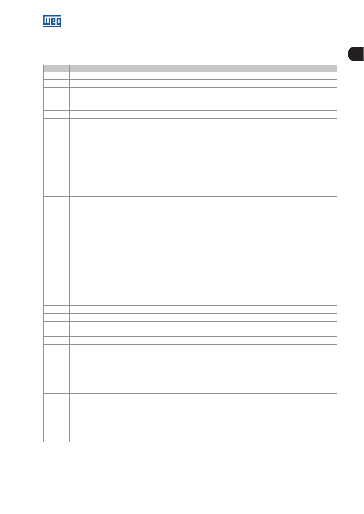
QUICK REFERENCE OF PARAMETERS, ALARMS AND FAULTS
Param. Description Adjustable Range Factory Setting Prop. Page
P000 Access to Parameters 0 to 9999 1 5-1
P001 Speed Reference 0 to 9999 ro 15-1
P002 Output Speed (Motor) 0 to 9999 ro 15-1
P003 Motor Current 0.0 to 40.0 A ro 15-1
P004 DC Link Voltage (Ud) 0 to 524 V ro 15-1
P005 Output Frequency (Motor) 0.0 to 400.0 Hz ro 15-1
P006 Inverter Status 0 = Ready
P007 Output Voltage 0 to 240 V ro 15-2
P009 Motor Torque -200.0 to 200.0 % ro, VVW 15- 3
P011 Output Cos
P012 DI8 to DI1 Status 0 to FF (hexa)
P013 DO4 to DO1 Status 0 to F (hexa)
(*)
P014
P015
P018 AI1 Value -100.0 to 100.0 % ro 12-1
P019
P022 FI Value in Hz 1 to 3000 Hz ro 12-9
P023 Main SW Version 0.00 to 99.99 ro 6-1
P024
P025
P027 Config. Acces. IO 0 = Without Accessory
P028 Config. Comm. Acces. 0 = Without Accessory
AO1 Value 0.0 to 100.0 % ro 12-6
(*)
AO2 Value 0.0 to 100.0 % ro 12-6
(*)
AI2 Value -100.0 to 100.0 % ro 12-1
(*)
IO Acces. SW Version 0.00 to 99.99 ro 6 -1
(**)
Comm. Acces. SW Version 0.00 to 99.99 ro 6-1
φ
1 = Run
2 = Undervoltage
3 = Fault
4 = Self-Tuning
5 = Configuration
6 = DC Braking
7 = Reserved
8 = Fire Mode
-1.0 0 to 1.0 0 ro 15-3
Bit 0 = DI1
Bit 1 = DI2
Bit 2 = DI3
Bit 3 = DI4
Bit 4 = DI5
Bit 5 = DI6
Bit 6 = DI7
Bit 7 = DI8
Bit 0 = DO1
Bit 1 = DO2
Bit 2 = DO3
Bit 3 = DO4
1 = CFW300-IOAR
2 = CFW300-IODR
3 = CFW300-IOADR
4 = CFW300-IOAENC
5 = Reserved
6 = CFW300-IODF
7 to 10 = Reserved
1 = CFW300-HMIR
2 = CFW300-CBLT
3 = CFW300-CCAN
4 = CFW300-CPDP
5 = Reserved
6 = CFW300-IODF
7 to 10 = Reserved
ro 15-2
ro 12-11
ro 12-20
ro 6-1
ro 6-1
0
CFW300 | 0-1
Page 10

Quick Reference of Parameters, Alarms and Faults
0
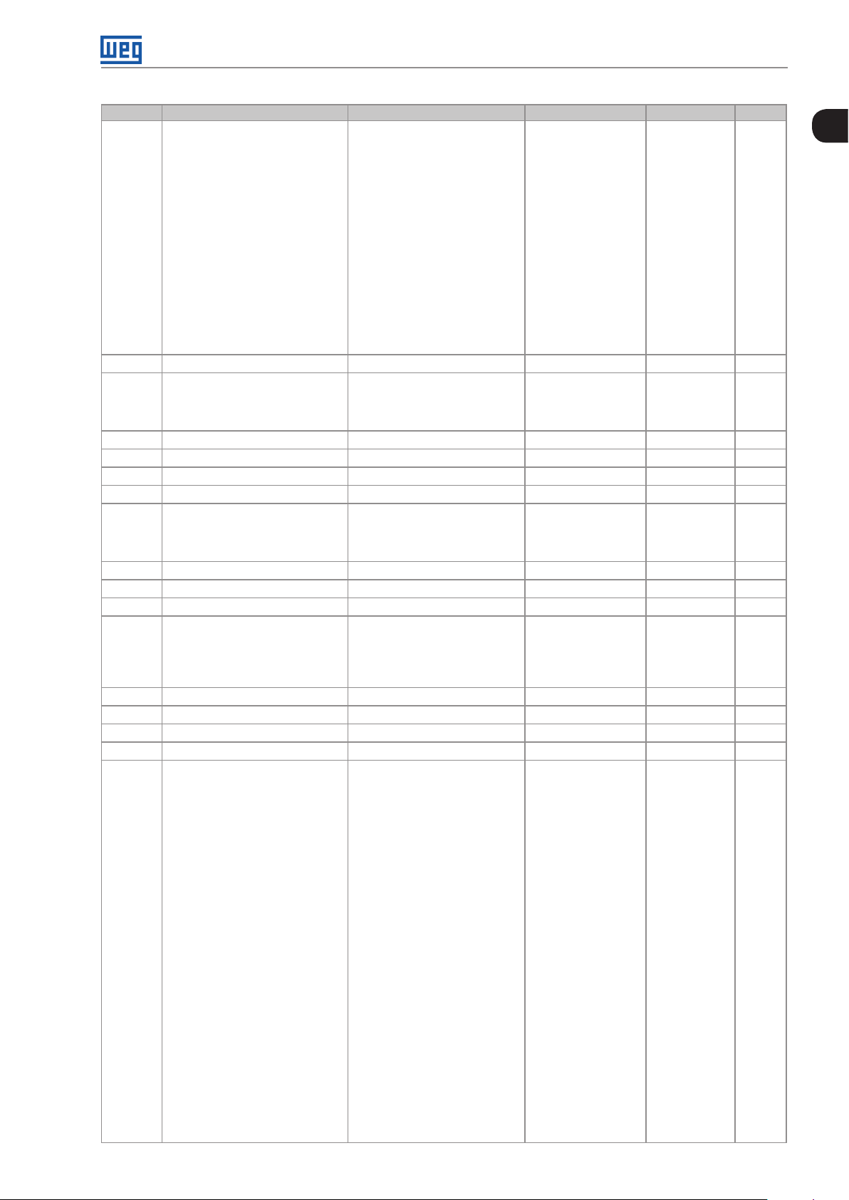
Param. Description Adjustable Range Factory Setting Prop. Page
P029 Power HW Configuration 0 = Non-identified
1 = 1.6 A / 110 V
2 = 2.6 A / 110 V
3 = 4.0 A / 110 V
4 = 6.0 A / 110 V
5 = 1.6 A / 220 V
6 = 2.6 A / 220 V
7 = 4.0 A / 220 V
8 = 6.0 A / 220 V
9 = 7.3 A / 220 V
10 = 10 A / 220 V
11 = 15.2 A / 220 V
P030 Module Temperature 0.0 to 200.0 ºC (32 °F to 392 °F) ro 15-4
P037 Motor Overload Ixt 0.0 to 100.0 % ro 14-2
P038 Encoder Speed -9999 to 9999 rpm ro 15-4
P039 Encoder Pulse Counter 0 to 9999 ro 15- 4
P045 Enabled Fan Time 0 to FFFF (hexa) ro 15-4
P047 CONFIG Status 0 to 999 ro 5-5
P048 Present Alarm 0 to 999 ro 14-6
P049 Present Fault 0 to 999 ro 14-6
P050 Last Fault 0 to 999 ro 14-6
P051 Last Fault Current 0.0 to 40.0 A ro 14-6
P052 Last Fault DC Link 0 to 524 V ro 14-7
P053 Last Fault Frequency 0.0 to 400.0 Hz ro 14 -7
P054 Last Fault Temperature 0.0 to 200.0 ºC (32 °F to 392 °F) ro 14-7
P060 Second Fault 0 to 999 ro 14- 6
P070 Third Fault 0 to 999 ro 14-6
P080 Last Fault in “Fire Mode” 0 to 999 0 ro 14- 6
P081 Second Fault in “Fire Mode” 0 to 999 0 ro 14-6
P082 Third Fault in “Fire Mode” 0 to 999 0 ro 14- 6
P100 Acceleration Time 0.1 to 999.9 s 5.0 s 11-1
P101 Deceleration Time 0.1 to 999.9 s 10.0 s 11-1
P102 Acceleration Time 2nd Ramp 0.1 to 999.9 s 5.0 s 11-1
P103 Deceleration Time 2nd Ramp 0.1 to 999.9 s 10.0 s 11-2
P104 S Ramp 0 = Inactive
1 = Active
P105 Selection 1st/2nd Ramp 0 = 1st Ramp
1 = 2nd Ramp
2 = DIx
3 = Serial/USB
4 = Reserved
5 = CO/DN/DP
6 = SoftPLC
P106 Emer. R. Acceleration Time 0.1 to 999.9 s 5.0 s 11- 2
P107 Emer. R. Time Deceleration 0.1 to 999.9 s 5.0 s 11-2
P120 Speed Ref. Backup 0 = Inactive
1 = Active
2 = Backup by P121
P121 Reference via HMI 0.0 to 400.0 Hz 3.0 Hz 7- 8
P122 JOG Reference -400.0 to 400.0 Hz 5.0 Hz 7- 8
P124 Multispeed Ref. 1 -400.0 to 400.0 Hz 3.0 Hz 7-8
P125 Multispeed Ref. 2 -400.0 to 400.0 Hz 10.0 (5.0) Hz 7-8
P126 Multispeed Ref. 3 -400.0 to 400.0 Hz 20.0 (10.0) Hz 7-8
P127 Multispeed Ref. 4 -400.0 to 400.0 Hz 30.0 (20.0) Hz 7-8
P128 Multispeed Ref. 5 -400.0 to 400.0 Hz 40.0 (30.0) Hz 7-9
P129 Multispeed Ref. 6 -400.0 to 400.0 Hz 50.0 (40.0) Hz 7-9
P130 Multispeed Ref. 7 -400.0 to 400.0 Hz 60.0 (50.0) Hz 7-9
P131 Multispeed Ref. 8 -400.0 to 400.0 Hz 66.0 (55.0) Hz 7-9
P133 Minimum Frequency 0.0 to 400.0 Hz 3.0 Hz 7-7
P134 Maximum Frequency 0.0 to 400.0 Hz 66.0 (55.0) Hz 7-7
According the
inverter model
0 cfg 11-2
0 11- 3
1 7-7
ro 6 -2
0-2 | CFW300
Page 11

Quick Reference of Parameters, Alarms and Faults
Param. Description Adjustable Range Factory Setting Prop. Page
P135 Maximum Output Current 0.0 to 40.0 A 1.5 x I
nom
11- 6
P136 Manual Torque Boost 0.0 to 30.0 % 5.0 % V/f 9-4
P137 Automatic Torque Boost 0.0 to 30.0 % 0.0 % V/f 9-5
P138 Slip Compensation -10.0 to 10.0 % 0.0 % V/f 9-6
P139 Output Current Filter 0.000 to 9.999 s 0.05 s 8-1
P140 Slip Com. Filter 0.000 to 9.999 s 0.5 s VVW 8 -1
P142 Maximum Output Voltage 0.0 to 100.0 % 100.0 % cfg, V/f 9-5
P143 Intermediate Output Voltage 0.0 to 100.0 % 50.0 % cfg, V/f 9-5
P145 Field Weakening Start Frequency 0.0 to 400.0 Hz 60.0 (50.0) Hz cfg, V/ f 9-5
P146 Intermediate Frequency 0.0 to 400.0 Hz 30.0 (25.0) Hz cfg, V/f 9-5
P149 DC Link Comp. 0 = Inactive
0 cfg 11- 4
1 = Active
P150 Type Ud V/f Regulator 0 = Hold_Ud and Desac_LC
0 cfg 11- 4
1 = Accel_Ud and Desac_LC
2 = Hold_Ud and Hold_LC
3 = Accel_UD and Hold_LC
P151 DC Link Regulation Level 348 to 460 V According the
11- 4
inverter model
P153 Dynamic Braking Level 348 to 460 V According the
13-1
inverter model
P156 Rated Speed Overload Current 0.1 to 2.0 x I
P157 Overload Curr. 50 % Nom. Speed 0.1 to 2.0 x I
P158 Overload Curr. 20 % Nom. Speed 0.1 to 2.0 x I
nom
nom
nom
1.2 x I
1.2 x I
1.2 x I
nom
nom
nom
14-1
14-1
14-1
P178 Rated Flux 50.0 to 150.0 % 100.0 % VVW 10-3
P200 Password 0 = Inactive
0 cfg 5-2
1 = Active
2 to 9999 = New Password
P202 Type of Control 0 = V/f
0 cfg 8 -1
1 = V/f Quadratic
2 to 4 = Not Used
5 = V V W
P204 Load/Save Parameters 0 to 4 = Not Used
0 cfg 5-4
5 = Load WEG 60 Hz
6 = Load WEG 50 Hz
7 = Load User
8 = Not Used
9 = Save User
10 = Not Used
11 = Load Default SoftPLC
12 and 13 = Reserved
P205 Main Display Parameter 0 to 999 2 5-2
P207 Bar Graph Parameter 0 to 999 3 5-2
P208 Factor Scale Ref. 1 to 9999 600 (500) 5-2
P209 Ref. Eng. Unit 0 = Without Unit
3 5-3
1 = Without Unit
2 = Volts (V)
3 = Hertz (Hz)
4 = Without Unit
5 = Percent (%)
6 = Without Unit
7 = Rotation/min. (rpm)
P210 Ref. Decimal Point 0 = wxyz
1 5-3
1 = wxy.z
2 = wx.yz
3 = w.xyz
P213 Bar Graph Scale Factor 1 to 9999 1 x I
nom
5-3
P219 Red. Switch. Freq. 0.0 to 15.0 Hz 15.0 Hz cfg 6-3
0
CFW300 | 0-3
Page 12

Quick Reference of Parameters, Alarms and Faults
0
Param. Description Adjustable Range Factory Setting Prop. Page
P220 LOC/REM Selection Source 0 = Always Local
1 = Always Remote
2 and 3 = Not Used
4 = DIx
5 = Serial/USB (LOC)
6 = Serial/USB (REM)
7 and 8 = Not Used
9 = CO/DN/DP (LOC)
10 = CO/DN/DP (REM)
11 = SoftPLC
P221 LOC Reference Sel. 0 = HMI Keys
1 = AI1
2 = AI2
3 = Not Used
4 = FI
5 = AI1 + AI2 > 0
6 = AI1 + AI2
7 = E.P.
8 = Multispeed
9 = Serial/USB
10 = Not Used
11 = CO/DN/DP
12 = SoftPLC
13 = Not Used
14 = AI1 > 0
15 = AI2 > 0
16 = Not Used
17 = FI > 0
P222 REM Reference Sel. See Options in P221 1 cfg 7- 4
P223 LOC FWD/REV Sel. 0 = Forward
1 = Reverse
2 and 3 = Not Used
4 = DIx
5 = Serial/USB (FWD)
6 = Serial/USB (REV)
7 and 8 = Not Used
9 = CO/DN/DP (FWD)
10 = CO/DN/DP (REV)
11 = Not Used
12 = SoftPLC
P224 LOC Run/Stop Sel. 0 = HMI Keys
1 = DIx
2 = Serial/USB
3 = Not Used
4 = CO/DN/DP
5 = SoftPLC
P225 LOC JOG Selection 0 = Disabled
1 = Not Used
2 = DIx
3 = Serial/USB
4 = Not Used
5 = CO/DN/DP
6 = SoftPLC
P226 REM FWD/REV Selection See Options in P223 4 cfg 7-5
P227 REM Run/Stop Selection See Options in P224 1 cfg 7-5
P228 REM JOG Selection See Options in P225 2 cfg 7-6
P229 Stop Mode Selection 0 = Ramp to Stop
1 = Coast to Stop
P230 Dead Zone (AIs and FI) 0 = Inactive
1 = Active
0 cfg 7-4
0 cfg 7-4
0 cfg 7- 5
0 cfg 7- 5
1 cfg 7- 6
0 cfg 7-13
0 cfg 12-1
0-4 | CFW300
Page 13
Quick Reference of Parameters, Alarms and Faults
Param. Description Adjustable Range Factory Setting Prop. Page
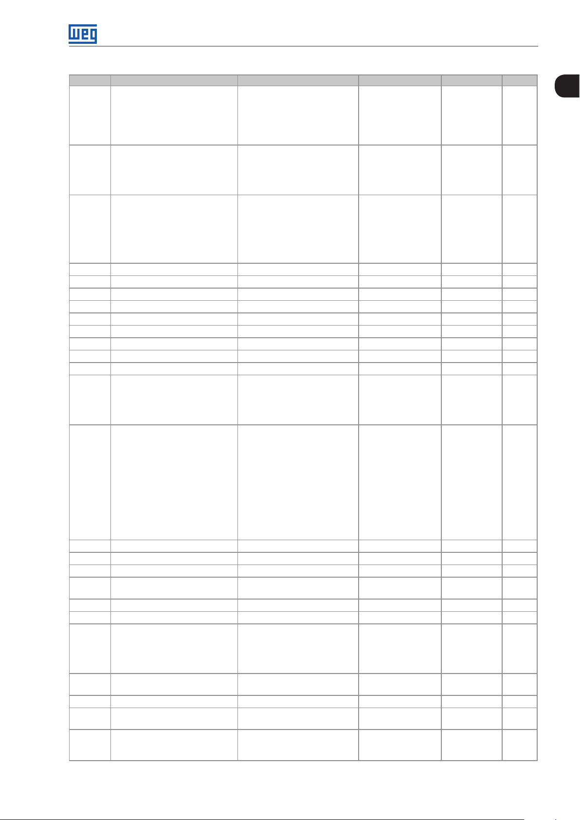
P231 AI1 Signal Function
0 = Speed Ref.
0 cfg 12-2
1 to 3 = Not Used
4 = PTC
5 and 6 = Not used
7 = SoftPLC
8 = Application Function 1
9 = Application Function 2
10 = Application Function 3
11 = Application Function 4
12 = Application Function 5
13 = Application Function 6
14 = Application Function 7
15 = Application Function 8
16 = Control Setpoint (PID
Controller Application)
17 = Process Variable (PID
Controller Application)
P232 AI1 Input Gain
P233 AI1 Input Signal
0.000 to 9.999
0 = 0 to 10 V / 20 mA
1.000 12-3
0 12- 4
1 = 4 to 20 mA
2 = 10 V / 20 mA to 0
3 = 20 to 4 mA
P234 AI1 Input Offset
P235 AI1 Input Filter
(*)
P236
P237
P238
AI2 Signal Function
(*)
AI2 Input Gain
(*)
AI2 Input Signal
-100.0 to 100.0 %
0.00 to 16.00 s
See Options in P231
0.000 to 9.999
0 = 0 to 10 V / 20 mA
0.0 % 12- 3
0.00 s 12-3
0 cfg 12-2
1.000 12-3
0 12- 4
1 = 4 to 20 mA
2 = 10 V / 20 mA to 0
3 = 20 to 4 mA
(*)
P239
P240
AI2 Input Offset
(*)
AI2 Input Filter
P245 Input Filter in Freq. FI
P246 FI Input in Freq.
-100.0 to 100.00 %
0.00 to 16.00 s
0.00 to 16.00 s
0 = Inactive
0.0 % 12- 3
0.00 s 12-3
0.00 s 12-9
0 cfg 12-10
1 = Active in DI1
2 = Active in DI2
3 = Active in DI3
4 = Active in DI4
P247 FI Input Gain
P248 FI Minimum Input
P249 FI Input Offset
P250 FI Maximum Input
(*)
P251
AO1 Output Function
0.000 to 9.999
1 to 3000 Hz
-100.0 to 100.0 %
1 to 3000 Hz
0 = Speed Ref.
1.000 12-10
100 Hz 12 -10
0.0 % 12-10
1000 Hz 12-10
2 12-7
1 = Not Used
2 = Real Speed
3 and 4 = Not Used
5 = Output Current
6 = Not Used
7 = Active Current
8 to 10 = Not Used
11 = Motor Torque
12 = SoftPLC
13 to 15 = Not Used
16 = Motor I x t
17 = Not Used
18 = Content of P696
19 = Content of P697
20 = Not Used
21 = Application Function 1
22 = Application Function 2
23 = Application Function 3
24 = Application Function 4
25 = Application Function 5
26 = Application Function 6
27 = Application Function 7
28 = Application Function 8
29 = Control Setpoint (PID
Controller Application)
30 = Process Variable (PID
Controller Application)
CFW300 | 0-5
0
Page 14

Quick Reference of Parameters, Alarms and Faults
0
Param. Description Adjustable Range Factory Setting Prop. Page
(*)
P252
P253
AO1 Output Gain 0.000 to 9.999 1.000 12- 8
(*)
AO1 Output Signal 0 = 0 to 10 V
0 12- 8
1 = 0 to 20 mA
2 = 4 to 20 mA
3 = 10 to 0 V
4 = 20 to 0 mA
5 = 20 to 4 mA
(*)
P254
P255
P256
P263 DI1 Input Function 0 = Not Used
AO2 Output Function See Options in P251 5 12-7
(*)
AO2 Output Gain 0.000 to 9.999 1.000 12- 8
(*)
AO2 Output Signal See Options in P253 0 12-8
1 cfg 12-12
1 = Run/Stop
2 = General Enable
3 = Fast Stop
4 = Forward Run
5 = Reverse Run
6 = Start
7 = Stop
8 = Direction of Rotation
9 = LOC/REM
10 = JOG
11 = Increase E.P.
12 = Decelerate E.P.
13 = Multispeed
14 = 2nd Ramp
15 to 17 = Not Used
18 = No Ext. Alarm
19 = No Ext. Fault
20 = Reset
21 to 23 = Not Used
24 = Disab. Flying Start
25 = Not Used
26 = Lock Prog.
27 to 31 = Not Used
32 = 2nd Ramp Multispeed
33 = 2nd Ramp E.P. Ac.
34 = 2nd Ramp E.P. De.
35 = 2nd Ramp FWD Run
36 = 2nd Ramp REV Run
37 = Turn ON / Ac. E.P.
38 = De. E.P. / Turn OFF
39 = Stop
40 = Safety Switch
41 = Application Function 1
42 = Application Function 2
43 = Application Function 3
44 = Application Function 4
45 = Application Function 5
46 = Application Function 6
47 = Application Function 7
48 = Application Function 8
49 = Activate Fire Mode
50 = Manual/Automatic PID
(Only DI2 for P903 = 1)
51 = Increase Setpoint
Command (PE) (Only DI3 for
P903 = 1)
52 = Decrease Setpoint
Command (Only DI4 for P903 = 1)
53 = 1st DI Control Setpoint
(Only DI3 for P903 = 1)
54 = 2st DI Control Setpoint
(Only DI4 for P903 = 1)
P264 DI2 Input Function See Options in P263 8 cfg 12-12
P265 DI3 Input Function See Options in P263 0 cfg 12-12
P266 DI4 Input Function See Options in P263 0 cfg 12-12
(*)
P267
P268
P269
DI5 Input Function See Options in P263 0 cfg 12-12
(*)
DI6 Input Function See Options in P263 0 cfg 12-12
(*)
DI7 Input Function See Options in P263 0 cfg 12-12
0-6 | CFW300
Page 15

Quick Reference of Parameters, Alarms and Faults
Param. Description Adjustable Range Factory Setting Prop. Page
(*)
P270
P271
DI8 Input Function See Options in P263 0 cfg 12-12
(*)
DIs Signal 0 = All DIx NPN
0 cfg 12 -14
1 = (DI1...DI4) PNP
2 = (DI5...DI8) PNP
3 = (DI1...DI8) PNP
(*)
P275
DO1 Output Function 0 = Not Used
13 12-21
1 = F* > Fx
2 = F > Fx
3 = F < Fx
4 = F = F*
5 = Not Used
6 = Is > Ix
7 = Is < Ix
8 = Torque > Tx
9 = Torque < Tx
10 = Remote
11 = Run
12 = Ready
13 = No Fault
14 = No F070
15 = Not Used
16 = No F021/F022
17 = Not Used
18 = No F072
19 = 4-20 mA OK
20 = P0695 Value
21 = Forward
22 to 23 = Not Used
24 = Ride-Through
25 = Pre-Charge OK
26 = Fault
27 = Not Used
28 = SoftPLC
29 to 34 = Not Used
35 = No Alarm
36 = No Fault/ Alarm
37 = Application Function 1
38 = Application Function 2
39 = Application Function 3
40 = Application Function 4
41 = Application Function 5
42 = Application Function 6
43 = Application Function 7
44 = Application Function 8
45 = Fire Mode
46 = Process Variable Low Level
(A760/F761) (For P903 = 1)
47 = Process Variable High Level
(A762/F763) (For P903 = 1)
(*)
P276
P277
P278
DO2 Output Function See Options in P275 0 12-21
(*)
DO3 Output Function See Options in P275 0 12-21
(*)
DO4 Output Function See Options in P275 0 12-21
P281 Fx Frequency 0.0 to 400.0 Hz 3.0 Hz 12-23
P282 Fx Hysteresis 0.0 to 15.0 Hz 0.5 Hz 12-2 3
P290 Ix Current 0 to 40 A 1.0 x I
12-23
nom
P293 I x To r q u e 0 to 200 % 100 % 12-23
P295 Inv. Rated Current 1.6 to 15.2 A According inverter
ro 6-3
model
P296 Line Rated Voltage 0 = Reserved
1 = 110 / 127 Vac
According inverter
model
ro 6-3
2 = 200 / 240 Vac or 310 Vdc
P297 Switching Frequency 2.5 to 15.0 kHz 5.0 kHz cfg 6-3
P299 Start Braking Time 0.0 to 15.0 s 0.0 s 11- 8
P300 Stop Braking Time 0.0 to 15.0 s 0.0 s 11-9
P301 Start Frequency 0.0 to 400.0 Hz 3.0 Hz 11-10
P302 DC Braking Voltage 0.0 to 100.0 % 20.0 % 11-10
P303 Skip Frequency 1 0.0 to 400.0 Hz 0.0 Hz 11-10
0
CFW300 | 0-7
Page 16

Quick Reference of Parameters, Alarms and Faults
0
Param. Description Adjustable Range Factory Setting Prop. Page
P304 Skip Frequency 2 0.0 to 400.0 Hz 0.0 Hz 11-10
P306 Skip Band 0.0 to 25.0 Hz 0.0 Hz 11-10
P308 Serial Address 1 to 247 1 cfg 16-1
P310 Serial Baud Rate 0 = 9600 bits/s
1 cfg 16 -1
1 = 19200 bits/s
2 = 38400 bits/s
P3 11 Serial Bytes Config. 0 = 8 bits, No, 1
1 cfg 16 -1
1 = 8 bits, Even, 1
2 = 8 bits, Odd, 1
3 = 8 bits, No, 2
4 = 8 bits, Even, 2
5 = 8 bits, Odd, 2
P312 Serial Protocol 0 to 1 = Reserved
2 cfg 16-1
2 = Slave Modbus RTU
3 and 4 = Reserved
5 = Master Modbus RTU
P313 Action for Comminic. Error 0 = Inactive
1 16 -1
1 = Ramp Stop
2 = General Disable
3 = Go to LOC
4 = LOC Keep Enab
5 = Cause Fault
P314 Serial Watchdog 0.0 to 999.0 s 0.0 s cfg 16 -1
P316 Serial Interf. Status 0 = Inactive
ro 16 -1
1 = Active
2 = Watchdog Error
P320 Flying Start/Ride-Through 0 = Inactive
0 cfg 11-7
1 = Flying Start
2 = FS / RT
3 = Ride-Through
P331 Voltage Ramp 0.2 to 60.0 s 2.0 s 11-7
P332 Dead Time 0.1 to 10.0 s 1.0 s 11-7
P340 Auto-Reset Time 0 to 255 s 0 s cfg 14-7
P352 Fan Control Configuration 0 = OFF
2 cfg 14- 3
1 = ON
2 = CT
(*)
P358
Encoder Fault Config. 0 = Off
3 cfg 14- 8
1 = F067 ON
2 = F079 ON
3 = F067, F079 ON
(*)
P375
P397 Control Configuration 0000 to 000F (hexa)
Temperature NTC 0 to 100 ºC (32 °F to 212 °F) ro 12-5
000Bh cfg 8-2
Bit 0 = Slip Compens. Regen.
Bit 1 = Reserved
Bit 2 = IO Stabilization
Bit 3 = P297 Reduction
Temperature
P399 Motor Rated Efficiency 50.0 to 99.9 % 6 7. 0 % cfg, V V W 10- 4
P400 Motor Rated Voltage 0 to 240 V According to
cfg, V V W 10-4
Table 10.2 on page
10- 4
P401 Motor Rated Current 0.0 to 40.0 A 1.0 x I
nom
cfg 10 -4
P402 Motor Rated Speed 0 to 30000 rpm 1720 (1310) rpm cfg 10 -4
P403 Motor Rated Frequency 0 to 400 Hz 60 (50) Hz cfg 10-4
P404 Motor Rated Power 0 = 0.16 HP (0.12 kW)
1 = 0.25 HP (0.18 kW)
According to
inverter model
cfg, V V W 10-5
2 = 0.33 HP (0.25 kW)
3 = 0.50 HP (0.37 kW)
4 = 0.75 HP (0.55 kW)
5 = 1.00 HP (0.75 kW)
6 = 1.50 HP (1.10 kW)
7 = 2.00 HP (1.50 kW)
8 = 3.00 HP (2.20 kW)
9 = 4.00 HP (3.00 kW)
10 = 5.00 HP (3.70 kW)
(*)
P405
Encoder Pulse Number 32 to 9999 1024 cfg 10 -5
0-8 | CFW300
Page 17

Quick Reference of Parameters, Alarms and Faults
Param. Description Adjustable Range Factory Setting Prop. Page
P407 Motor Rated Power Factor 0.50 to 0.99 0.69 cfg, VV W 10- 5
P408 Run Self-Tuning 0 = No
P409 Stator Resistance 0.01 to 99.99 Ω According to
P510 Unit SoftPLC Eng. 0 = Without Unit
P511 SoftPLC Indication Form 0 = wxyz
P580 Fire Mode Configuration 0 = Inactive
P582 Auto-reset configuration 0 = Limited
P588 Energy Saving Max. Torque 0 to 85 % 0 cfg, V/f 9-8
P589 Level of Minimum Applied Voltage 40 to 80 % 40 % cfg, V/f 9-8
P590 Energy Saving Minimum
Frequency
P591 Energy Saving Hysteresis 0 to 30 % 10 % cfg, V/f 9-9
P613 Software Revision -9999 a 9999 According to
P680 Logical Status 0 to FFFF (hexa)
P681 Speed in 13 bits 0 to FFFF (hexa) ro 16-1
P682 Serial/USB Control 0 to FFFF (hexa)
P683 Serial/USB Speed Ref. 0 to FFFF (hexa) ro 16 -1
1 = Yes
1 = A
2 = V
3 = Hz
4 = s
5 = %
6 = ºC (°F)
7 = rpm
1 = wxy.z
2 = wx.yz
3 = w.xyz
1 = Active
2 = Active / P0134
3 = Reserved
4 = Active / Gen. Disable
1 = Unlimited
12.0 Hz to 400.0 Hz 20.0 Hz cfg, V/f 9-9
Bit 0 = Reserved
Bit 1 = Run Command
Bit 2 = Fire Mode
Bit 3 and 4 = Reserved
Bit 5 = 2nd Ramp
Bit 6 = Config. Status
Bit 7 = Alarm
Bit 8 = Running
Bit 9 = Enabled
Bit 10 = Forward
Bit 11 = JOG
Bit 12 = Remote
Bit 13 = Undervoltage
Bit 14 = Reserved
Bit 15 = Fault
Bit 0 = Ramp Enable
Bit 1 = General Enable
Bit 2 = Run Forward
Bit 3 = JOG Enable
Bit 4 = Remote
Bit 5 = 2nd Ramp
Bit 6 = Reserved
Bit 7 = Fault Reset
Bit 8 to 15 = Reserved
0 cfg, VVW 10 -5
cfg, V V W 10-6
inverter model
5-6
1 5-6
0 cfg 11-12
0 cfg 11-12
ro 6-1
Soft ware revisio n
ro 7-12
16- 4
ro 16 -1
0
CFW300 | 0-9
Page 18

Quick Reference of Parameters, Alarms and Faults
0
Param. Description Adjustable Range Factory Setting Prop. Page
(**)
P684
CO/DN/DP Control 0 to FFFF (hexa)
ro 7-12
Bit 0 = Ramp Enable
Bit 1 = General Enable
Bit 2 = Run Forward
Bit 3 = JOG Enable
Bit 4 = Remote
Bit 5 = 2nd Ramp
Bit 6 = Reserved
Bit 7 = Fault Reset
Bit 8 to 15 = Reserved
(**)
P685
P695 Value for DOx 0 to F (hexa)
CO/DN/DP Speed Ref. 0 to FFFF (hexa) ro 16-2
ro 16-4
Bit 0 = DO1
Bit 1 = DO2
Bit 2 = DO3
Bit 3 = DO4
(*)
P696
P697
P700
Value 1 for AOx 0 to FFFF (hexa) ro 16- 4
(*)
Value 2 for AOx 0 to FFFF (hexa) ro 16- 4
(**)
CAN Protocol 1 = CANopen
2 16-2
2 = DeviceNet
(**)
P701
P702
CAN Address 0 to 127 63 16-2
(**)
CAN Baud Rate 0 = 1 Mbps/Auto
0 16-2
1 = Reserved/Auto
2 = 500 Kbps
3 = 250 Kbps
4 = 125 Kbps
5 = 100 Kbps/Auto
6 = 50 Kbps/Auto
7 = 20 Kbps/Auto
8 = 10 Kbps/Auto
(**)
P703
Bus Off Reset 0 = Manual
1 16-2
1 = Automatic
(**)
P705
CAN Controller Status 0 = Inactive
ro 16-2
1 = Auto-baud
2 = CAN Active
3 = Warning
4 = Error Passive
5 = Bus Off
6 = No Bus Power
(**)
P706
P707
P708
P709
P710
CAN RX Telegrams 0 to 9999 ro 16-2
(**)
CAN TX Telegrams 0 to 9999 ro 16-2
(**)
Bus Off Counter 0 to 9999 ro 16-2
(**)
CAN Lost Messages 0 to 9999 ro 16-2
(**)
DeviceNet I/O Instances 0 = ODVA Basic 2 W
0 16-2
1 = ODVA Extend 2 W
2 = Manuf. Spec. 2 W
3 = Manuf. Spec. 3 W
4 = Manuf. Spec. 4 W
5 = Manuf. Spec. 5 W
6 = Manuf. Spec. 6 W
(**)
P7 11
P712
P713
P714
P715
P716
P717
P718
P719
DeviceNet Reading #3 0 to 1199 0 16-2
(**)
DeviceNet Reading #4 0 to 1199 0 16-2
(**)
DeviceNet Reading #5 0 to 1199 0 16-2
(**)
DeviceNet Reading #6 0 to 1199 0 16-2
(**)
DeviceNet Writing #3 0 to 1199 0 16-3
(**)
DeviceNet Writing #4 0 to 1199 0 16-3
(**)
DeviceNet Writing #5 0 to 1199 0 16-3
(**)
DeviceNet Writing #6 0 to 1199 0 16-3
(**)
DeviceNet Network Status 0 = Offline
5 ro 16 - 3
1 = OnLine, Not Conn.
2 = OnLine Connect.
3 = Connection Timed Out
4 = Link Failure
5 = Auto-Baud
(**)
P720
DNet Master Status 0 = Run
ro 16-3
1 = Idle
0-10 | CFW300
Page 19
Quick Reference of Parameters, Alarms and Faults
Param. Description Adjustable Range Factory Setting Prop. Page
(**)
P721
CANopen Com. Status 0 = Inactive
ro 16-3
1 = Reserved
2 = Communic. Enabled
3 = Error Ctrl. Enable
4 = Guarding Error
5 = Heartbeat Error
P722
(**)
CANopen Node Status 0 = Inactive
ro 16-3
1 = Initialization
2 = Stopped
3 = Operational
4 = Preoperational
(**)
P74 0
Profibus Communication
Status
0 = Inactive
1 = Access Error
ro 16-3
2 = Offline
3 = Configuration Error
4 = Parameterization Error
5 = Clear Mode
6 = Online
(**)
P742
P74 3
P74 4
P74 5
P74 6
P747
P74 8
P74 9
P750
P751
Profibus Reading # 3 0 to 1199 0 16-3
(**)
Profibus Reading # 4 0 to 1199 0 16-3
(**)
Profibus Reading # 5 0 to 1199 0 16-3
(**)
Profibus Reading # 6 0 to 1199 0 16-3
(**)
Profibus Writing # 3 0 to 1199 0 16-3
(**)
Profibus Writing # 4 0 to 1199 0 16-3
(**)
Profibus Writing # 5 0 to 1199 0 16-3
(**)
Profibus Writing # 6 0 to 1199 0 16-3
(**)
Profibus Address 1 to 126 1 16-3
(**)
Profibus Telegram Selection 1 = Standard Telegram 1
1 16-3
2 = Telegram 100
3 = Telegram 101
4 = Telegram 102
5 = Telegram 103
(**)
P754
Profibus Baud Rate 0 = 9.6 kbit/s
0 ro 16 - 4
1 = 19.2 kbit/s
2 = 93.75kbit/s
3 = 187.5 kbit/s
4 = 500 kbit/s
5 = Not Detected
6 = 1500 kbit/s
7 = 3000 kbit/s
8 = 6000 kbit/s
9 = 12000 kbit/s
10 = Reserved
11 = 45.45 kbit/s
(**)
P770
P771
P840
P8 41
Bluetooth Name 0 to 9999 0 16-1
(**)
Bluetooth Password 0 to 9999 1234 16-2
(*)
IR Control Command 0 to FFFF (hexa) ro 12-20
(*)
IR Control Selection 0 = Without Display
0 cfg
1 = With Display
(*)
P842
P843
P900 SoftPLC Status 0 = No Application
Quick View 1 IR 0 to 959 2 5-3
(*)
Quick View 2 IR 0 to 959 375 5-3
0 ro 17-1
1 = Installing Application
2 = Incompat. Application
3 = Application Stopped
4 = Application Running
P901 SoftPLC Command 0 = Stop Program
0 cfg 17-1
1 = Run Program
P902 Scan Cycle Time 0 to 9.999 s 0 ro 17-1
P903 SoftPLC Application 0 = User
1 cfg 17-1
1 = PID Controller
P904 Action for SoftPLC Application not
Running
0 = Inactive
1 = Generate Alarm (A708)
0 cfg 17- 2
2 = Generate Fault (F709)
0
CFW300 | 0-11
Page 20

Quick Reference of Parameters, Alarms and Faults
0
Param. Description Adjustable Range Factory Setting Prop. Page
SoftPLC Parameter Configuration for the User's Application (P903 = 0)
P910 SoftPLC Parameter 1 -9999 to 9999 0 17-2
P911 SoftPLC Parameter 2 -9999 to 9999 0 17-2
P912 SoftPLC Parameter 3 -9999 to 9999 0 17-2
P913 SoftPLC Parameter 4 -9999 to 9999 0 17- 2
P914 SoftPLC Parameter 5 -9999 to 9999 0 17-2
P915 Sof tPLC Parameter 6 -9999 to 9999 0 17- 2
P916 SoftPLC Parameter 7 -9999 to 9999 0 17-2
P9 17 SoftPLC Parameter 8 -9999 to 9999 0 17-2
P918 SoftPLC Parameter 9 -9999 to 9999 0 17-2
P919 SoftPLC Parameter 10 -9999 to 9999 0 17-2
P920 SoftPLC Parameter 11 -9999 to 9999 0 17-2
P921 SoftPLC Parameter 12 -9999 to 9999 0 17-2
P922 SoftPLC Parameter 13 -9999 to 9999 0 17-2
P923 SoftPLC Parameter 14 -9999 to 9999 0 17-2
P924 SoftPLC Parameter 15 -9999 to 9999 0 17-2
P925 SoftPLC Parameter 16 -9999 to 9999 0 17-2
P926 SoftPLC Parameter 17 -9999 to 9999 0 17-2
P927 SoftPLC Parameter 18 -9999 to 9999 0 17-2
P928 SoftPLC Parameter 19 -9999 to 9999 0 17-2
P929 SoftPLC Parameter 20 -9999 to 9999 0 17-2
P930 SoftPLC Parameter 21 -9999 to 9999 0 17-2
P931 SoftPLC Parameter 22 -9999 to 9999 0 17-2
P932 SoftPLC Parameter 23 -9999 to 9999 0 17-2
P933 SoftPLC Parameter 24 -9999 to 9999 0 17-2
P934 SoftPLC Parameter 25 -9999 to 9999 0 17-2
P935 SoftPLC Parameter 26 -9999 to 9999 0 17-2
P936 SoftPLC Parameter 27 -9999 to 9999 0 17-2
P937 SoftPLC Parameter 28 -9999 to 9999 0 17-2
P938 SoftPLC Parameter 29 -9999 to 9999 0 17-2
P939 SoftPLC Parameter 30 -9999 to 9999 0 17-2
P940 SoftPLC Parameter 31 -9999 to 9999 0 17-2
P9 41 SoftPLC Parameter 32 -9999 to 9999 0 17-2
P942 SoftPLC Parameter 33 -9999 to 9999 0 17-2
P943 SoftPLC Parameter 34 -9999 to 9999 0 17-2
P944 SoftPLC Parameter 35 -9999 to 9999 0 17-2
P945 SoftPLC Parameter 36 -9999 to 9999 0 17-2
P946 SoftPLC Parameter 37 -9999 to 9999 0 17-2
P947 SoftPLC Parameter 38 -9999 to 9999 0 17-2
P948 SoftPLC Parameter 39 -9999 to 9999 0 17-2
P949 SoftPLC Parameter 40 -9999 to 9999 0 17-2
P950 SoftPLC Parameter 41 -9999 to 9999 0 17-2
P951 SoftPLC Parameter 42 -9999 to 9999 0 17-2
P952 SoftPLC Parameter 43 -9999 to 9999 0 17-2
P953 SoftPLC Parameter 44 -9999 to 9999 0 17-2
P954 SoftPLC Parameter 45 -9999 to 9999 0 17-2
P955 SoftPLC Parameter 46 -9999 to 9999 0 17-2
P956 SoftPLC Parameter 47 -9999 to 9999 0 17-2
P957 SoftPLC Parameter 48 -9999 to 9999 0 17-2
P958 SoftPLC Parameter 49 -9999 to 9999 0 17-2
P959 SoftPLC Parameter 50 -9999 to 9999 0 17-2
0-12 | CFW300
Page 21

Quick Reference of Parameters, Alarms and Faults
Param. Description Adjustable Range Factory Setting Prop. Page
SoftPLC Parameter Configuration for PID Controller Application (P903 = 1)
P910 PID Controller Application Version 0.00 to 90.00 ro 18-8
P911 Control Setpoint -9999 to 9999 [SPLC Eng. Un.] 200 rw 18-8
P912 Control Setpoint 1 -9999 to 9999 [SPLC Eng. Un.] 200 18-8
P913 Control Setpoint 2 -9999 to 9999 [SPLC Eng. Un.] 230 18-8
P914 Control Setpoint 3 -9999 to 9999 [SPLC Eng. Un.] 180 18-8
P915 Control Setpoint 4 -9999 to 9999 [SPLC Eng. Un.] 160 18-8
P916 Control Process Variable -9999 to 9999 [SPLC Eng. Un.] ro 18-9
P9 17 PID Controller Output 0.0 to 100.0 % ro 18-9
P918 PID Controller Setpoint in Manual
Mode
P919 PID Controller Logical Status Bit 0 = Sleep Mode Active (A750)
P920 Selection of the Control Setpoint
Source
P921 Selection of the Control Process
Variable Source
P922 Minimum Sensor Level of the
Control Process Variable
P923 Maximum Sensor Level of the
Control Process Variable
P924 Value for Low Level Alarm for the
Control Process Variable;
P925 Time for Low Level Fault for the
Control Process Variable
P926 Value for High Level Alarm for the
Control Process Variable
P927 Time for High Level Fault for the
Control Process Variable
P928 Selection of the PID Controller
Control Action
P929 PID Controller Operation Mode 0 = Manual
0.0 to 400.0 Hz 0.0 Hz 18-9
Bit 1 = PID in Manual (0) /
Automatic (1)
Bit 2 = PV Low Level (A760)
Bit 3 = PV Low Level (F761)
Bit 4 = PV High Level (A762)
Bit 5 = PV High Level (F763)
Bit 6 to 15 = Reserved
0 = Control Setpoint via HMI or
Communication Networks (P911)
1 = Control Setpoint via Analog
Input AI1
2 = Control Setpoint via Analog
Input AI2
3 = Control Setpoint via
Electronic Potentiometer (EP)
4 = Two Setpoints via Digital
Input DI3 (P912 and P913)
5 = Three Setpoints via Digital
Inputs DI3 and DI4 (P912, P913
and P914)
6 = Four Setpoints via Digital
Inputs DI3 and DI4 (P912, P913,
P914 and P915)
1 = Control Process Variable via
Analog Input AI1
2 = Control Process Variable via
Analog Input AI2
3 = Control Process Variable via
Difference between Analog Input
AI1 and AI2
-9999 to 9999 [SPLC Eng. Un.] 0 18 -12
-9999 to 9999 [SPLC Eng. Un.] 400 18-12
-9999 to 9999 [SPLC Eng. Un.] 100 18 -13
0 to 9999 s 0 s 18-13
-9999 to 9999 [SPLC Eng. Un.] 350 18-13
0 to 9999 s 0 s 18-14
0 = Disable PID Controller
1 = Enable PID Controller in
Direct Mode
2 = Enable PID Controller in
Reverse Mode
1 = Automatic
2 = Select Control to Manual (0)
or Automatic (1) via digital input
DI2
0 cfg 18 -10
1 cfg 18 -12
0 cfg 18 -14
2 18-15
ro 18-9
0
CFW300 | 0-13
Page 22

Quick Reference of Parameters, Alarms and Faults
0
Param. Description Adjustable Range Factory Setting Prop. Page
P930 Automatic Adjustment of the PID
Controller Setpoint
P931 Proportional Gain 0.00 to 99.99 1.00 18-16
P932 Integral Gain 0.00 to 99.99 5.00 18 -16
P933 Derivative Gain 0.00 to 99.99 0.00 18-16
P934 PID Controller Sampling Period 0.050 to 9.999 s 0 .1 0 0 s cfg 18-16
P935 Filter for the PID Controller Control
Setpoint
P936 Deviation of the Control Process
Variable to Wake Up
P937 Time to Wake Up 0 to 9999 s 5 s 18 -18
P938 Motor Speed to activate the Sleep
Mode
P939 Time to activate de Sleep Mode 0 to 9999 s 10 s 18 -18
(*) Only available when some IO expansion accessory (CF W300-IOAR, CFW300-IODR, CFW300-IOADR or CFW30 0-IOAENC) is present (connected). For
further information, refer to the respective accessory guide.
(**) Only available when some communication accessory (CFW300-CBLT, CFW300-CCAN or CFW300-CPDP) is present (connected). For further information,
refer to the respective accessor y guide.
0 = P911 inactive and P918
inactive
1 = P911 active and P918 inactive
2 = P911 inactive and P918 active
3 = P911 active and P918 active
0.000 to 9.999 s 0.15 0 s 18-17
-9999 to 9999 [SPLC Eng. Un.] 30 18-17
0.0 to 400.0 Hz 0.0 Hz 18-18
0 18-15
ro = read only parameter.
V/f = parameter available in V/f mode.
cfg = configuration parameter, value can only be changed with the motor stopped.
VV W = parameter available in V VW mode.
0-14 | CFW300
Page 23

Quick Reference of Parameters, Alarms and Faults
Fault / Alarm Description Possible Causes
A046
Motor Overload
A050
Power Module
Overtemperature
Motor overload alarm. Settings of P156 is too low for the used motor.
Overload on the motor shaft.
Overtemperature alarm from the power
module temperature sensor (NTC).
High temperature at IGBTs. P030> Level A050, according to
Table 14.1 on page 14-3.
High ambient temperature around the inverter (> 50 °C (>
122 °F)) and high output current. For further information, refer
to of the user’s manual available for download on the website:
www.weg.net.
Blocked or defective fan.
Heatsink is too dirty, preventing the air flow.
A090
External Alarm
A128
Telegram Reception
Timeout
A133
No Power Supply on
the CAN Interface
External alarm via DIx (option “no
external alarm” in P263 to P270).
Alarm that indicates serial
communication fault. It indicates the
equipment stopped receiving valid serial
telegrams for a period longer than the
setting in P314.
It indicates that the CAN interface has no
power supply between pins 25 and 29 of
the connector.
Wiring on DI1 to DI8 inputs are open or have poor contact.
Check network installation, broken cable or fault/poor contact
on the connections with the network, grounding.
Ensure the master always sends telegrams to the equipment in
a time shorter than the setting in P314.
Disable this function in P314.
Measure if there is voltage within the allowed range between
pins 25 and 29 of the CAN interface connector.
Check if the power supply cables are not misconnected or
inverted.
Check for contact problems on the cable or connector of the
CAN interface.
A134
Bus Off
Buss off error detected on the CAN
interface.
Check for short circuit on the CAN circuit transmission cable.
Check if the cables are not misconnected or inverted.
Check if all the network devices use the same baud rate.
Check if the termination resistors with the right specification
were installed only at the end of the main bus.
Check if the CAN network was properly installed.
A135
Node Guarding/
Heartbeat
CANopen communication error control
detected communication error using the
guarding mechanism.
Check the times set on the master and on the slave for message
exchange. In order to prevent problems due to transmission
delays and time counting, it is recommended that the values
set for error detection by the slave be multiples of the times set
for message exchange on the master.
Check if the master is sending the guarding telegrams in the
time set.
Check problems in the communication that may cause missing
telegrams or transmission delays.
A136
Idle Master
Alarm indicates that the DeviceNet
network master is in Idle mode.
Set the switch that controls the master operation of the master
for Run or the corresponding bit on the configuration word of
the master software. If further information is needed, refer to the
documentation of the master used.
A137
DeviceNet Connection
Timeout
A13 8
Profibus DP Interface in
Clear Mode
A139
Offline Profibus DP
Interface
Alarm that indicates that one or more
DeviceNet connections timed out.
It indicates that the inverter received the
command from the Profibus DP network
master to go into clear mode.
It indicates interruption in the
communication between the Profibus
DP network master and the inverter. The
Profibus DP communication interface
went into offline status.
Check the network master status.
Check network installation, broken cable or fault/poor contact
on the connections with the network.
Check the network master status, ensuring it is in the run mode.
Check if the network master is correctly configured and operating
proper l y.
Check for short-circuit or poor contact on the communication
cables.
Check if the cables are not misconnected or inverted.
Check if the termination resistors with the right value were
installed only at the end of the main bus.
Check the network installation in general - cabling, grounding.
A140
Profibus DP Module
Access Error
It indicates error in the access to the
Profibus DP communication module
data.
Check if the Profibus DP module is correctly fitted.
Hardware errors due to improper handling or installation of the
accessory, for instance, may cause this error. If possible, carry
out tests by replacing the communication accessory.
A16 3
Signal Fault AI1
Analog input signal AI1 at 4 to 20 mA or
20 to 4 mA is below 4 to 20 mA.
Current signal on the analog input AI1 interrupted or null.
Parameterization error on analog input AI1.
4...20 mA
A16 4
Signal Fault AI2
Analog input signal AI2 at 4 to 20 mA or
20 to 4 mA is below 4 to 20 mA.
Current signal on the analog input AI2 interrupted or null.
Parameterization error on analog input AI2.
4...20 mA
A177
Replace Fan
A211
Drive in Fire Mode
Alarm to replace the fan
(P045 > 50000 hours).
Maximum number of operation hours of the heatsink fan
exceeded.
Indicates that the drive is in Fire Mode. The digital input programmed for activating the Fire Mode is
active.
0
CFW300 | 0-15
Page 24

Quick Reference of Parameters, Alarms and Faults
0
Fault / Alarm Description Possible Causes
A700
Remote HMI
Communication
A702
Inverter Disabled
No communication with remote HMI, but
here is frequency command or reference
for this source.
This failure occurs when there is a
SoftPLC movement block active and the
Check if the communication interface with the HMI is properly
configured in parameter P312.
HMI cable disconnected.
Check if the drive General Enable command is active.
“General Enable” command is disabled.
A704
Two Movem. Enabled
It occurs when 2 or more SoftPLC
movement blocks are enabled at the
Check the user’s program logic.
same time.
A706
Refer. Not Progr. SPLC
This failure occurs when a SoftPLC
movement block is enabled and the
Check the programming of the references in the Local and/or
Remote mode (P221 and P222).
speed reference is not programmed for
the SoftPLC.
A708
SoftPLC Application
Stopped
A712
SPLC Protected Against
Copy
SoftPLC Application not running SoftPLC Application is stopped (P901 = 0 and P900 = 3).
SoftPLC state presents application incompatible with the
firmware version of the CFW300.
It occurs when there is an attempt to
copy the SoftPLC application protected
against copies.
Attempt to copy WLP application protected against copies
(“never permit copies”).
Attempt to copy WLP from a copy protected against copies (“no
permission to copy from a copy”).
A750 to A799
User’s Alarms for
SoftPLC
F021
Undervoltage on the
DC Link
Alarm range intended for the user’s
application developed in the SoftPLC
function.
Undervoltage fault on the intermediate
circuit.
Defined by the user’s application developed in the SoftPLC
function.
Wrong voltage supply; check if the data on the inverter label
comply with the power supply and parameter P296.
Supply voltage too low, producing voltage on the DC Link
below the minimum value (Level F021) according to Table 14.4
on page 14-4:
Ud < 200 Vdc.
Phase fault in the input.
Fault in the pre-charge circuit.
F022
Overvoltage on the DC
Link
Overvoltage fault on the intermediate
circuit.
Wrong voltage supply; check if the data on the inverter label
comply with the power supply and parameter P296.
Supply voltage is too high, producing voltage on the DC Link
above the maximum value (Level F022) according to Table 14.4
on page 14-4.
Load inertia is too high or deceleration ramp is too fast.
P151 setting is too high.
F031
Fault in Communication
with IOs Expansion
Main control cannot establish the
communication link with the IOs
expansion accessory.
Accessory damaged.
Poor connection of the accessory.
Problem in the identification of the accessory; refer to P027.
Accessory
F032
Fault in Communication
with IO Communication
Main control cannot establish
the communication link with the
communication acccessory.
Accessory damaged.
Poor connection of the accessory.
Problem in the identification of the accessory; refer to P028.
Accessory
F033
VVW Self-tuning Fault
Stator resistance setting fault P409. Stator resistance value in P409 does not comply with the
inverter power.
Motor connection error; turn off the power supply and check the
motor terminal box and the connections with the motor terminals.
Motor power too low or too high in relation to the inverter.
F051
IG B Ts
Overtemperatures
Overtemperature fault measured on the
temperature sensor of the power pack.
High temperature at IGBTs. P030> Level A051, according to
Table 14.1 on page 14-3.
High ambient temperature around the inverter (> 50 °C
(> 122 °F)) and high output current. For further information,
refer to of the user's manual available for download on the
website: www.weg.net.
Blocked or defective fan.
Heatsink is too dirty, preventing the air flow.
F067
Incorrect Encoder/
Motor Wiring
F070
Overcurrent/Shortcircuit
F072
Motor Overload
Fault related to the phase relation of the
encoder signals.
Overcurrent or short-circuit on the
output, DC link or braking resistor.
Motor overload fault, according to
actuation defined by the curve of Figure
14.1 on page 14-2.
Output motor cables U, V, W are inverted.
Encoder channels A and B are inverted.
Encoder was not properly mounted.
Short-circuit between two motor phases.
IGBTs module in short-circuit or damaged.
Start with too short acceleration ramp.
Start with motor spinning without the Flying Start function.
P156, P157 or P158 setting is too low in relation to the motor
operating current.
Overload on the motor shaft.
0-16 | CFW300
Page 25

Quick Reference of Parameters, Alarms and Faults
Fault / Alarm Description Possible Causes
F078
Motor Overtemperature
F079
Encoder Signal Fault
F080
CPU Fault (Watchdog)
F081
End of User’s Memory
F082
Fault in Data
Transfer (MMF)
Overtemperature fault measured on the
motor temperature sensor (Triple PTC)
via analog input AIx
Overload on the motor shaft.
Load cycle is too high (high number of starts and stops per
minute).
High ambient temperature around the motor.
Poor contact or short-circuit (3k9 < R
Motor thermistor not installed.
Motor shaft is stuck.
Fault of encoder signals absent. Wiring between encoder and interface accessory to encoder
broken.
Encoder defective.
Fault related to the supervision
algorithm of the inverter main CPU.
Fault of end of memory to save user’s
parameter table.
Fault in data transfer using MMF
accessory.
Electric noise.
Inverter firmware fault.
Attempt to save (P204 = 9) more than 32 parameters (with values
different from the factory default) on the User parameter table.
Attempt to download data from the flash memory module to the
inverter with the inverter energized.
Attempt to download a SoftPLC application incompatible with
the destination inverter.
Problems saving data downloaded to the inverter.
F084
Auto-diagnosis Fault
F091
External Fault
F228
Timeout in Receipt of
Telegrams
F233
No Power Supply on
the CAN Interface
Fault related to the automatic
identification algorithm of the inverter
hardware.
External fault via DIx (“no external
fault” in P263 to P270).
Indicates fault in the serial
communication. It indicates the
equipment stopped receiving valid serial
telegrams for a period longer than the
setting in P314.
It indicates that the CAN interface has no
power supply between pins 25 and 29 of
the connector.
Poor contact in the connection between the main control and
the power pack.
Hardware not compatible with the firmware version.
Defect on the internal circuits of the inverter.
Wiring on DI1 to DI8 inputs are open or have poor contact.
Check network installation, broken cable or fault/poor contact
on the connections with the network, grounding.
Ensure the master always sends telegrams to the equipment in
a time shorter than the setting in P314.
Disable this function in P314.
Measure if there is voltage within the allowed range between
pins 25 and 29 of the CAN interface connector.
Check if the power supply cables are not misconnected or
inverted.
Check for contact problems on the cable or connector of the
CAN interface.
F234
Bus Off
Buss off error detected on the CAN
interface.
Check for short circuit on the CAN circuit transmission cable.
Check if the cables are not misconnected or inverted.
Check if all the network devices use the same baud rate.
Check if the termination resistors with the right specification
were installed only at the end of the main bus.
Check if the CAN network was properly installed.
F235
Node Guarding/
Heartbeat
CANopen communication error control
detected communication error using the
guarding mechanism.
Check the times set on the master and on the slave for message
exchange. In order to prevent problems due to transmission
delays and time counting, it is recommended that the values
set for error detection by the slave be multiples of the times set
for message exchange on the master.
Check if the master is sending the guarding telegrams in the
time set.
Check problems in the communication that may cause missing
telegrams or transmission delays.
F236
Idle Master
Fault indicates that the DeviceNet
network master is in Idle mode.
Set the switch that controls the master operation for Run
or the corresponding bit on the configuration word of the
master software. If further information is needed, refer to the
documentation of the master used.
F237
DeviceNet Connection
Timeout
F238
Profibus DP Interface in
Clear Moder
F239
Offline Profibus DP
Interface
Fault that indicates that one or more
DeviceNet connections timed out.
It indicates that the inverter received a
command from the Profibus DP network
master to enter the clear mode.
It indicates an interruption in the
communication between the Profibus DP
network master and the inverter. The
Profibus DP communication interface
went into offline status.
Check the network master status.
Check network installation, broken cable or fault/poor contact
on the connections with the network.
Verify the network master status, making sure it is in the
execution mode (Run).
Check if the network master is correctly configured and operating
proper l y.
Check for short-circuit or poor contact on the communication
cables.
Check if the cables are not misconnected or inverted.
Check if the termination resistors with the right value were
installed only at the end of the main bus.
Check the network installation in general - cabling, grounding.
< 0k1).
PTC
0
CFW300 | 0-17
Page 26

Quick Reference of Parameters, Alarms and Faults
0
Fault / Alarm Description Possible Causes
F240
Profibus DP Module
Access Fault
F701
Remote HMI
Communication Fault
F709
SPLC Application
Stopped
F710
Size of the SoftPLC
Application
F7 11
Fault on SoftPLC
Application
F750 to F799
User’s Faults for
SoftPLC
A750
Sleep Mode Active
A760
Low Level of the Control
Process Variable
F761
Low Level of the Control
Process Variable
A762
High Level of the
Control Process
Variable
F763
High Level of the
Control Process
Variable
A790
Speed reference source
not programmed for the
SoftPLC
It indicates fault in the access to the
Profibus DP communication module
data.
No communication with the remote HMI;
however, there is command or frequency
reference for this source.
SoftPLC application not running. SoftPLC application stopped (P901 = 0 and P900 = 3).
The size of the SoftPLC user’s program
exceeded the maximum memory
capacity.
Fault found in SoftPLC user’s program. SoftPLC user’s program stored on flash memory is corrupted.
Fault range intended for the user’s
application developed in the SoftPLC
function.
Faults and Alarms for PID Controller Application (P903 = 1)
It indicates that the PID Controller is in
the sleep mode.
It indicates that the level of the control
process variable (P916) is low.
It indicates the motor was switched
off due to the low level of the control
process variable.
It indicates that the level of the control
process variable (P916) is high.
It indicates the motor was switched
off due to the high level of the control
process variable.
It indicates that parameters of the speed
reference sources in local mode (P221)
and in remote mode (P222) were not
programmed for the SoftPLC.
Check if the Profibus DP module is correctly fitted.
Hardware errors due to improper handling or installation of the
accessory, for instance, may cause this fault. If possible, carry
out tests by replacing the communication accessory.
Check that the HMI communication interface is properly
configured in parameter P312.
HMI cable disconnected.
SoftPLC state presents incompatible application with the
CFW300 firmware version.
The logic implemented on the WLP is too large. Check project
size.
Timeout during execution of SoftPLC scan cycle.
Defined by the user’s application developed in the SoftPLC
function.
The motor speed remained below the value programmed in
P938 for the time programmed in P939.
The control process variable (P916) remained below the value
programmed in P924 for 150 ms.
The control process variable (P916) remained below the value
programmed in P924 for a certain time (P925).
The control process variable (P916) remained above the value
programmed in P926 for 150 ms.
The control process variable (P916) remained above the value
programmed in P926 for a certain time (P927).
The PID Controller was enabled, the Run/Stop command is
active, and neither of the two parameters of the speed reference
source was programmed in 12 (SoftPLC).
0-18 | CFW300
Page 27
Safety Instructions
1 SAFETY INSTRUCTIONS
This manual contains the information necessary for the correct setting of the CFW300 frequency inverter.
It was developed to be used by people with proper technical training or qualification to operate this kind of
equipment. These people must follow the safety instructions defined by local standards. The noncompliance with
the safety instructions may result in death risk and/or equipment damage.
1.1 SAFETY WARNINGS IN THIS MANUAL
DANGER!
The procedures recommended in this warning have the purpose of protecting the user against death,
serious injuries and considerable material damage.
ATTENTION!
The procedures recommended in this warning have the purpose of avoiding material damage.
NOTE!
The information mentioned in this warning is important for the proper understanding and good
operation of the product.
1.2 SAFETY WARNINGS IN THE PRODUCT
1
The following symbols are fixed to the product, as a safety warning:
High voltages present.
Components sensitive to electrostatic discharge.
Do not touch them.
Mandatory connection to the protective earth (PE).
Connection of the shield to the ground.
Hot surface.
1.3 PRELIMINARY RECOMMENDATIONS
DANGER!
Only qualified personnel, familiar with the CFW300 inverter and related equipment must plan or
perform the installation, start-up, operation and maintenance of this equipment.
The personnel must follow the safety instructions described in this manual and/or defined by local
standards.
The noncompliance with the safety instructions may result in death risk and/or equipment damage.
CFW300 | 1-1
Page 28
Safety Instructions
NOTE!
For the purposes of this manual, qualified personnel are those trained in order to be able to:
1. Install, ground, power up and operate the CFW300 in accordance with this manual and the safety
1
legal procedures in force.
2. Use the protective equipment in accordance with the relevant standards.
3. Give first aid.
DANGER!
Always disconnect the general power supply before touching any electric component associated
to the inverter.
Many components may remain loaded with high voltages and/or moving (fans), even after the AC
power supply input is disconnected or turned off. Wait for at least ten minutes in order to guarantee
the full discharge of the capacitors. Always connect the frame size of the equipment to the protective
earth (PE) at the proper point for that.
ATTENTION!
Electronic boards have components sensitive to electrostatic discharge. Do not touch directly the
component parts or connectors. If necessary, first touch the grounded metallic frame size or use
proper grounding strap.
Do not execute any applied potential test on the inverter!
If necessary, contact WEG.
NOTE!
Frequency inverters may interfere in other electronic equipments. Observe the recommendations
of chapter 3 Installation and Connection of the user’s manual in order to minimize these effects.
Read the user’s manual completely before installing or operating this inverter.
1-2 | CFW300
Page 29

General Information
2 GENERAL INFORMATION
2.1 ABOUT THE MANUAL
This manual presents information necessary for the configuration of all the functions and parameters of the CFW300
frequency inverter. This manual must be used together with the user’s manual of the CFW300.
The text provides additional information so as simplify the use and programming of the CFW300 in certain
applications.
2.2 TERMINOLOGY AND DEFINITIONS
2.2.1 Terms and Definitions Used
I
: inverter rated current by P295.
nom
Rectifier: input circuit of the inverters that transforms the input AC voltage into DC. It is formed by high-power
diodes.
IGBT: insulated gate bipolar transistor - basic component part of the output inverter bridge. It works as an electronic
switch in the saturated (closed switch) and cut-off (open switch) modes.
DC Link: intermediary circuit of the inverter; voltage in direct current obtained by rectifying the power supply
alternate voltage or external supply; it supplies the output inverter bridge with IGBTs.
Pre-Charge Circuit: charges the capacitors of the DC link with limited current, avoiding current peaks in the
inverter power-up.
NTC: resistor whose resistance value in ohms decreases proportionally to the increase of the temperature; it is
used as a temperature sensor in power packs.
2
HMI: human-machine interface; device which allows controlling the motor, viewing and changing the inverter
parameters. It features keys to control the motor, navigation keys and graphic LCD display.
PE: protective earth.
PWM: pulse width modulation - modulation by pulse width; pulsed voltage that supplies the motor.
Switching Frequency: switching frequency of the IGBTs of the inverter bridge, normally expressed in kHz.
General Enable: when activated, it accelerates the motor by acceleration ramp and Run/Stop = Run. When
disabled, the PWM pulses will be immediately blocked. It may be controlled by digital input set for this function,
via serial or via SoftPLC.
Run/Stop: inverter function which, when activated (run), accelerates the motor by acceleration ramp up to the
reference frequency and, when deactivated (stop), decelerates the motor by deceleration ramp. It may be controlled
by digital input set for this function, via serial or via SoftPLC.
Heatsink: metal part designed to dissipate the heat produced by power semiconductors.
Amp, A: ampere; unit of measurement of electric current.
°F: Fahrenheit degree.
°C: Celsius degrees; unit of measurement of temperature.
AC: alternate current.
DC: direct current.
CFW300 | 2-1
Page 30

General Information
hp (HP): horse power = 746 Watts (unit of measurement of power, normally used to indicate mechanical power of
electric motors).
Hz: hertz; unit of measurement of frequency.
kHz: kilohertz = 1000 Hertz.
2
mA: miliampere = 0.001 ampere.
Nm: Newton meter; unit of torque.
rms: root mean square; effective value.
rpm: revolutions per minute; unit of measurement of rotation.
s: second; unit of measurement of time.
V: volts; unit of measurement of electric voltage.
Ω: ohms; unit of measurement of electric resistance.
2.2.2 Numerical Representation
The decimal numbers are represented by means of digits without suffix. Parameters P012, P013, P045, P397,
P680, P682, P684, P685, P695, P697, P757, P758 and P840 are represented in hexadecimal numbers.
2-2 | CFW300
Page 31

About the CFW300
3 ABOUT THE CFW300
The CFW300 frequency inverter is a high performance product which enables speed and torque control of threephase induction motors. This product provides the user with the options of vector (VVW) or scalar (V/f) control,
both programmable according to the application.
In the vector mode (VVW), the operation is optimized for the used motor, providing a better performance in terms
of speed regulation.
The scalar mode (V/f) is recommended for simpler applications, such as the activation of most pumps and fans.
In those cases, it is possible to reduce the motor and inverter losses using the option "Quadratic V/f", which
results in energy saving. The V/f mode is used when more than a motor is activated by an inverter simultaneously
(multi-motor applications).
The main components of the CFW300 can be viewed in the block diagram of Figure 3.1 on page 3-1, Figure
3.2 on page 3-2 and Figure 3.3 on page 3-3. The mechanical project was designed to simplify the connection
and maintenance, as well as to ensure the safety of the product.
3
Power
supply
R/L1/L (-UD)
S/L2/N (+UD)
T/L 3
Digital inputs
Analog input
1
1
Filter RFI
2
(DI1 to DI4)
(A I1)
4
Pre
load
5
Single-phase /
three-phase
rectifier
PE
Power
Control
HMI
4
DC Link
capacitor bank
Sources for electronics and interfaces
between power and control
Control
board
CPU
16 bits
Rsh
Inverter with IGBT
(RS-232, RS-485,
transistors
RS-485
3
Interfaces
USB, CANopen,
DeviceNet,
Profibus DP or
Bluetooth)
3
U/T1
Motor
V/T2
3~
W/T3
PE
HMI (remote)
PC
Software WPS
Analog output
Digital
output DO1
(RL1)
(AO1)
3
4
4
Flash memory
module
DC power supply connection available for specific models only.
1
Three-phase power supply connection available for specific models only.
2
Available as accessory.
3
Number of Inputs/Outputs depends on the I/O expansion accessory used.
4
Available as accessory only for models Single-phase.
5
Figure 3.1: Block diagram of CFW300 for frame size A 220 V
3
CFW300 | 3-1
Page 32

About the CFW300
U/T1
V/T2
L1/ L
Power
supply
3
L2/N
RFI Filter
1
PE
Single-phase
rectifier
Preload
Power
Control
DC Link
capacitor
bank
Rsh
Inverter
with IGBT
transistors
Motor
3~
W/T3
PE
HMI (remote)
1
Digital inputs
(DI1 to DI4)
Analog input
(A I1)
2
Sources for electronics and interfaces between
HMI
2
Available as accessory.
1
Number of Inputs/Outputs depends on the I/O expansion accessory used.
2
Figure 3.2: Block diagram of CF W300 for frame size A 110 V
power and control
Control
board
CPU
16 bits
RS-485
1
Interfaces (RS-
232, RS-485,
USB, CANopen,
DeviceNet, Profibus
DP or Bluetooth)
Flash memory
module
1
PC
1
Software
WPS
Analog output
(AO1)
2
Digital
output DO1
(RL1)
2
3-2 | CFW300
Page 33

About the CFW300
Power
supply
R/L1/L
S/L2/N
T/L 3
Filter RFI
5
Digital inputs
(DI1 to DI4)
PE
Three-phase
rectifier
1 1
+UD -UD +BR BR
Preload
DC Link
capacitor
bank
4 4
Rsh
Braking
IGBT
Inverter
with IGBT
transistors
U/T1
V/T2
W/T3
PE
Motor
3~
3
2
Power
Control
Sources for electronics and interfaces between
power and control
RS-485
2
Interfaces
HMI
Control
board
CPU
16 bits
(RS-232, RS-485,
USB, CANopen,
DeviceNet, Profibus
DP or Bluetooth)
2
3
HMI (remote)
PC
Software WPS
Analog output
(AO1)
3
Analo g input
(A I1)
3
Flash memory
module
DC power supply connection.
1
Available as accessory.
2
Number of Inputs/Outputs depends on the I/O expansion accessory used.
3
Braking resistor connection.
4
Available as accessory only for models Single-phase.
5
Figure 3.3: Block diagram of CF W300 for frame size B 220 V
Digital output
DO1 (RL1)
3
2
CFW300 | 3-3
Page 34

About the CFW300
Frame size A Frame size B
2
1
3
2
1
3
3
5
5
4
4
6
6
1 - HMI
2 - mounting supports (for DIN rail mounting)
3 - communication accessory cover
4 - cover of the IO expansion accessory
5 - protection cover of the connection of the IO expansion accessory
6 - fan with mounting support
Figure 3.4: Main components of the CFW300
3-4 | CFW300
Page 35

HMI and Basic Programming
4 HMI AND BASIC PROGRAMMING
4.1 USE OF THE HMI TO OPERATE THE INVERTER
Using the HMI, it is possible to command the inverter, view and adjust all of its parameters. The HMI presents the
following functions:
Selects (switches) between
the parameter number and its
value (position/content).
Decreases (decrements)
the frequency, parameter
number or parameter value.
Figure 4.1: HMI keys
4.2 INDICATIONS ON THE HMI DISPLAY
Inverter status
Direction of
rotation
Enables/Disables the inverter via
acceleration/deceleration ramp
(start/stop, according to P229).
Resets the inverter after a fault.
Increases (increments) the
frequency, parameter number
or parameter value.
Unit of measurement
(it refers to the value
of the main display)
4
Main display
Figure 4.2: Display areas
Bar Graph to monitor
the variable
4.3 OPERATING MODES OF THE HMI
When inverter is powered-up, the initial state of the HMI remains in the start-up mode as long as no faults, alarms,
undervoltages occur or no keys are pressed.
The setting mode is composed of two levels: Level 1 allows browsing the parameters. Level 2 allows the modification
of the parameter selected in level 1. At the end of this level, the modified value is saved when the key is pressed.
The Figure 4.3 on page 4-2 illustrates the basic browsing of the operating modes of the HMI.
CFW300 | 4-1
Page 36

HMI and Basic Programming
Start-up Mode
It is the initial status of the HMI after the successful power-up (without fault,
alarms or undervoltages).
Press the key to go to level 1 of the setting mode - parameter selection.
Pressing any other key will also change to the setting mode.
Setting Mode
Level 1:
This is the first level of the setting mode. The number of the parameter is shown
on the main display.
Use the and keys to find the desired parameter.
Press the key to go to level 2 of the setting mode - modification of the
parameter content.
Level 2:
The content of the parameter is shown on the main display.
4
Use the and keys to configure the new value for the selected parameter.
Press the key to confirm the modification (save the new value). After the
change is confirmed, the HMI returns to level 1 of the setting mode.
Figure 4.3: HMI operating modes
NOTE!
When the inverter is in the fault state, the main display indicates the number of the fault in the format
Fxxx. The browsing is allowed after pressing the key.
Monitoring
Setting
Level 1
Setting
Level 2
NOTE!
When the inverter is in the alarm state, the main display indicates the number of the alarm in the format
Axxx. The browsing is allowed after pressing the key, and then the indication "A" is displayed on
the unit of measurement display, flashing until the situation causing the alarm is solved.
4-2 | CFW300
Page 37
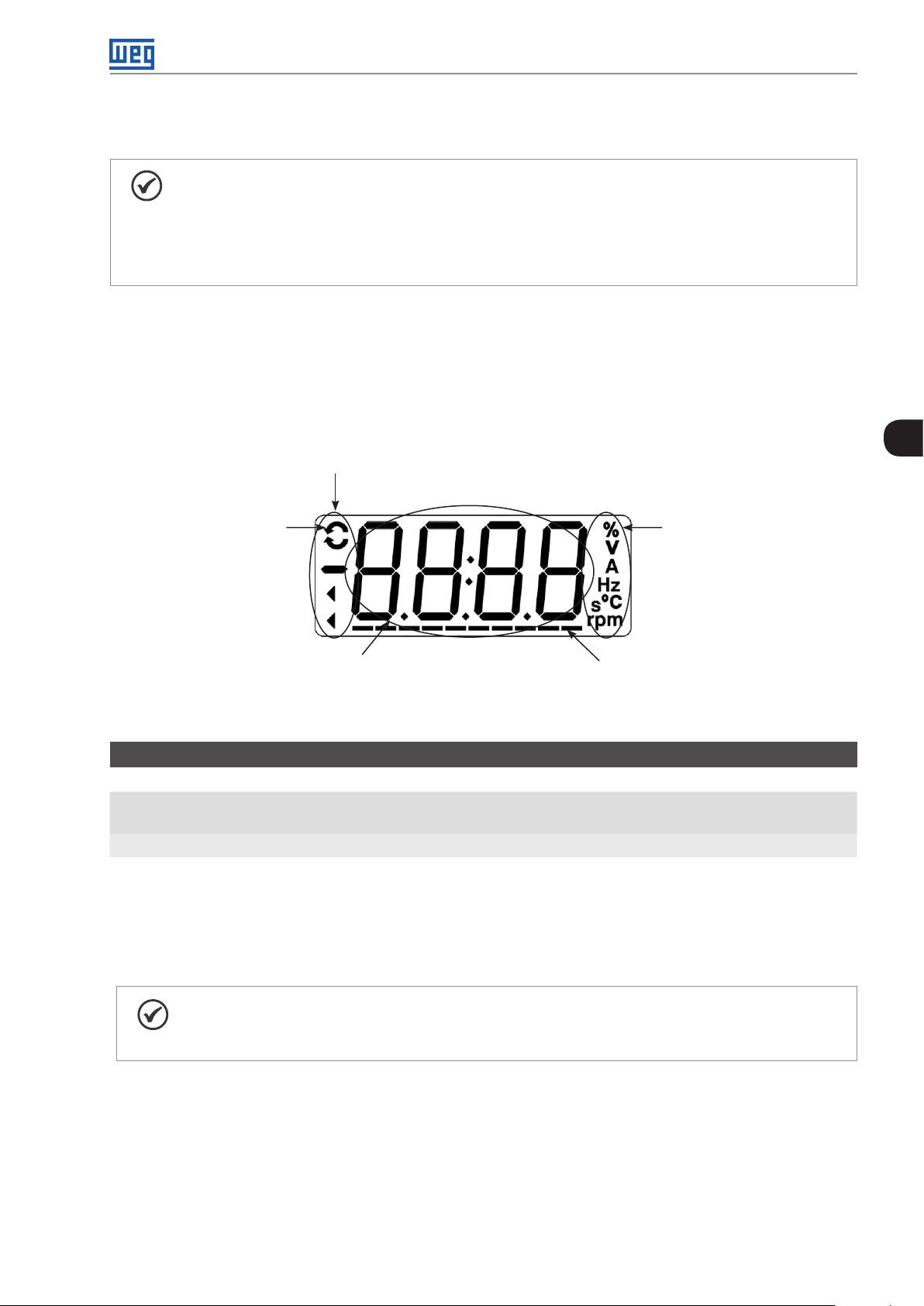
Programming Basic Instructions
5 PROGRAMMING BASIC INSTRUCTIONS
NOTE!
The inverter comes from the factory with the frequency (V/f 50/60 Hz mode) and voltage adjusted
according to the market.
The reset to factory default may change the content of the parameters related to frequency. In the
detailed description, some parameters have values between brackets, which represents the default
value for operation in 50 Hz; thus the value without brackets is the default for operation in 60 Hz.
5.1 ACCESS AND INDICATIONS OF HMI
Whenever the inverter is powered up, the HMI display goes to the start-up mode if no faults, alarms or undervoltages
are present. In order to simplify the reading of the inverter parameters, the display was designed to show two
parameters simultaneously, at the user’s discretion. One of those parameters (main display) is shown in the numeric
form and the other parameter as a bar graph. The parameter monitored by the bar graph is selected via P207, as
indicated in Figure 5.1 on page 5-1.
Inverter status
5
Direction of rotation
Main display - presents the content of parameter
(xxxx), number of the parameter (Pxxx), fault
(Fxxx) or alarm (Axxx) indication
Bar graph for parameter
monitoring (selected by P207)
Figure 5.1: Screen on initialization and display fields
Unit of measurement
for the main display
(selected by P209)
P000 - Access to Parameters
Adjustable
Range:
Properties:
Description:
Password input to release the access to the parameters. Once a password is saved in P200, the access to
the parameters is only allowed if this password is set in P000. After setting P000 with a password value, P000
will show "1" or "0", keeping the set password value hidden. Where "1" releases the access to parameters and
"0" locks the access to the parameters.
0 to 9999 Factory
Setting:
1
NOTE!
The view of parameter P000 on the HMI will only be available when the password is active (P200 = 1).
The access to the parameters and P000 is cleared together with the powering down of the inverter.
CFW300 | 5-1
Page 38

Programming Basic Instructions
P200 - Password
Adjustable
Range:
0 = Inactive
1 = Active
Factory
Setting:
0
2 to 9999 = New Password
Properties: cfg
Description:
It allows activating the password (by inserting a new value) or disabling it. For further details regarding the use
of this parameter, refer to Table 5.1 on page 5-2.
Table 5.1: Required procedure for each kind of action
Action Procedure
Activate password
5
Change password 1. Set the current value of the password (P000 = password)
Disable password
Disable password 1. Activate a factory default by means of P204
(1) It only allows changing the content of the parameters when P000 is equal to the value of the password.
(2) It is allowed to change the content of the parameters and P000 is inaccessible.
1. Set P200 with the desired value for the password (P200 = password)
2. The setting is completed, the new password is active and P200 is automatically adjusted for 1 (password
2. Set the desired value for the new password in P200 (P200 = new password)
3. The setting is completed, the new password is active and P200 is automatically adjusted for 1 (password
1. Set the current value of the password (P000 = password)
2. Set inactive password (P200 = 0)
3. The setting is completed, the password is disabled
2. The setting is completed, the password is disabled
active)
active)
(1)
(1)
(2)
(2)
P205 - Main Display Parameter Selection
Adjustable
Range:
Properties:
Description:
This parameter defines which parameter will be viewed on the HMI when the motor is enabled after initialization.
0 to 999 Factory
Setting:
2
P207 - Bar Graph Parameter Selection
Adjustable
Range:
Properties:
Description:
This parameter defines which parameter will be shown on the HMI bar graph.
0 to 999 Factory
Setting:
3
P208 - Reference Scale Factor
Adjustable
Range:
Properties:
1 to 9999 Factory
Setting:
600 (500)
Description:
This parameter allows adjusting the scale of the parameter speed reference P001 and output (motor) speed
P002 so as to convert the indication of frequency values applied to the motor (Hz) into angular speed in "rpm"
or a proportional value in "%", for instance.
5-2 | CFW300
Page 39

Programming Basic Instructions
Together with the unit in P209 and the decimal places in P210, the rated reference (P208) defines the speed
indication on the inverter HMI. According to the factory default of those parameters, the preset scale on the
inverter is in "Hz" and with a decimal place (60.0 Hz or 50.0 Hz). On the other hand, by setting P208 = 1800
or 1500, P209 = 7 and P210 = 0, a scale in "rpm" with no decimal places is defined (1800 rpm or 1500 rpm).
P209 - Reference Engineering Unit
Adjustable
Range:
Properties:
Description:
This parameter selects the engineering unit that will be presented on parameters P001 and P002.
0 and 1 = Without Unit
2 = V
3 = Hz
4 = Without Unit
5 = %
6 = Without Unit
7 = rpm
Factory
Setting:
P210 - Reference Decimal Point
Adjustable
Range:
Properties:
Description:
This parameter allows setting the form of indication of parameters P001 and P002.
0 = wxyz
1 = wxy.z
2 = wx.yz
3 = w.xyz
Factory
Setting:
3
5
1
P213 - Bar Graph Scale Factor
Adjustable
Range:
Properties:
Description:
This parameter configures the full scale (100 %) of the bar graph to indicate the parameter selected by P207.
1 to 9999 Factory
Setting:
1 x I
nom
P842 - Quick View 1 IR
P843 - Quick View 2 IR
Adjustable
Range:
Properties:
Description:
These parameters define which parameters (their respective values) will be viewed by using the of the
infrared remote control (available with the accessory CFW300-IOADR).
0 to 959 Factory
Setting:
P842 = 2
P843 = 375
CFW300 | 5-3
Page 40

Programming Basic Instructions
For further details, refer to the installation, configuration and operation guide of the CFW300-IOADR I/O
expansion module.
5.2 BACKUP PARAMETERS
The CFW300 BACKUP functions allow saving the inverter current parameter contents in a specific memory (virtual
EEPROM - flash memory area of the microprocessor), or overwrite the current parameters with the content of
the specified memory.
P204 - Load / Save Parameters
Adjustable
Range:
0 to 4 = Not Used
5 = Load WEG 60 Hz
Factory
Setting:
0
6 = Load WEG 50 Hz
7 = Load User
5
8 = Not Used
9 = Save User
10 = Not Used
11 = Load Default SoftPLC
12 and 13 = Reserved
Properties:
cfg
Description:
Table 5.2 on page 5-4 describes the actions performed by each option.
Table 5.2: Option of parameter P204
P204 Action
0 to 4 Not Used: no action
5 Load WEG 60 Hz: it loads the default parameters on the inverter with the factory default for 60 Hz
6 Load WEG 50 Hz: it loads the default parameters on the inver ter with the factory default for 50 Hz
7 Load User: it transfers the content of the memory from user parameter to the inverter current parameters
8 Not Used: no action
9 Save User: it transfers the current content of the parameters to the memory of user parameters
10 Not Used: no action
11 Load Default SoftPLC: it loads the factory default in SoftPLC parameters (P910 to P959)
12 and 13 Reserved
In order to load the parameters of user to the CFW300 operating area (P204 = 7) it is necessary that this area
be previously saved.
The operation of uploading this memory (P204 = 7), can also be done via digital inputs (DIx). For further details
referring to this programming, refer to Section 12.5 DIGITAL INPUTS on page 12-11.
NOTE!
When P204 = 5 or 6, parameters P295 (Inv. Rated Current), P296 (Line Rated Voltage) and P308
(Serial Address) are not changed.
NOTE!
In order to upload the user parameters (P204 = 7), the factory default must be uploaded first
(P204 = 5 or 6).
5-4 | CFW300
Page 41

Programming Basic Instructions
5.3 SITUATIONS FOR CONFIG STATUS
The Config status is indicated by the HMI "ConF" status, as well as in parameters P006 and P680. Such status
indicates that the CFW300 cannot enable the output PWM pulses because the inverter configuration is incorrect
or incomplete. For further details about indications of Config state on the HMI, refer to Chapter 15 READING
PARAMETERS on page 15-1.
P047 - Estado CONF
Adjustable
Range:
Properties:
0 a 999 Factory
Setting:
ro
Description:
The table below shows the situations of Config status, where the user can identify the origin condition through
parameter P047.
Table 5.3: Situations for Config status
P047 Condition
0 Out of CONFIG status. The HMI and parameters P006 and P680 must not indicate ConF
1 Two or more DIx (P263...P270) programmed for (4 = Forward Run)
2 Two or more DIx (P263...P270) programmed for (5 = Reverse Run)
3 Two or more DIx (P263...P270) programmed for (6 = Start)
4 Two or more DIx (P263...P270) programmed for (7 = Stop)
5 Two or more DIx (P263...P270) programmed for (8 = Direction of Rotation)
6 Two or more DIx (P263...P270) programmed for (9 = LOC/REM)
7 Two or more DIx (P263...P270) programmed for (11 = Accelerate E.P.)
8 Two or more DIx (P263...P270) programmed for (12 = Decelerate E.P.)
9 Two or more DIx (P263...P270) programmed for (14 = 2nd Ramp)
10 Reserved
11 Two or more DIx (P263...P270) programmed for (24 = Disable Flying Start)
12 Two or more DIx (P263...P270) programmed for (26 = Programming Off)
13 Reserved
14 Reserved
15 DIx (P263...P270) programmed for (4 = Forward Run) without DIx (P263...P270) programmed for (5 = Reverse Run) or the
opposite
16 DIx (P263...P270) programmed for (6 = Start) without DIx (P263...P270) programmed for (7 = Stop) or the opposite
17 P221 or P222 programmed for (8 = Multispeed) without DIx (P263...P270) programmed for (13 = Multispeed) or the opposite
18 P221 or P222 programmed for (7 = E.P.) without DIx (P263...P270) programmed for (11 = Accelerate E.P) or the opposite
19 P224 programmed for (1 = DIx) OR P227 programmed for (1 = DIx) without DIx (P263...P270) programmed for (1 = Run/Stop) AND
without DIx (P263...P270) programmed for (2 = General Enable) AND without DIx (P263...P270) programmed for (3 = Quick
Stop) AND without DIx (P263...P270) programmed for (4 = Forward Run) AND without DIx (P263...P270) programmed for
(6 = Start)
20 Reserved
21 P221 or P222 programmed for (8 = Multispeed) with DI1 (P263) AND DI2 (P264) OR DI1 (P263) AND DI5 (P267) OR DI1 (P263)
AND DI6 (P268) OR DI2 (P264) AND DI5 (P267) OR DI2 (P264) AND DI6 (P268) OR DI5 (P267) AND DI6 (P268) programmed
for (13 = Multispeed)
22 Minimum Frequency Reference (P133) greater than Maximum Frequency Reference (P134)
29 Two or more DIx (P263...270) programmed for (49 = Enable Fire Mode) OR two or more DOx (P275...P278) Programmed for
(45 = Fire Mode OR P580 programmed for 1, 2 or 4 (Fire Mode Enabled) without DIx programmed for (49 = Enable Fire Mode)
OR Dix programmed for (49 = Enable Fire Mode) OR Dox programmed for (47 = Fire Mode) and P580 programmed for
(0 = Fire Mode Disabled) or (3 = Reserved)
5
CFW300 | 5-5
Page 42

Programming Basic Instructions
5.4 ENGINEERING UNITS FOR SOFTPLC
This parameter group allows the user to configure the engineering units for indication on the HMI of the user's
parameters of the SoftPLC module.
P510 - SoftPLC Engineering Unit
Adjustable
Range:
5
Properties:
Description:
This parameter selects the engineering unit that will be viewed on the HMI, that is, any user’s parameter of the
SoftPLC which is related to the SoftPLC engineering unit will be viewed in this format.
0 = Without Unit
1 = A
2 = V
3 = Hz
4 = s
5 = %
6 = ºC (°F)
7 = rpm
Factory
Setting:
0
P511 - SoftPLC Indication Form
Adjustable
Range:
Properties:
Description:
0 = wxyz
1 = wxy.z
2 = wx.yz
3 = w.xyz
Factory
Setting:
1
This parameter selects the decimal point that will be viewed on the HMI, that is, any user’s parameter of the
SoftPLC which is related to the SoftPLC indication form will be viewed in this format.
NOTE!
The engineering unit may be selected in the “Configuration of the User’s Parameters” window in
the WPS program.
5-6 | CFW300
Page 43

Identification of the Inverter Model and Accessories
6 IDENTIFICATION OF THE INVERTER MODEL AND ACCESSORIES
In order to check the inverter model, see the code on the product nameplate on the side of the inverter.
Once the inverter model identification code is checked, it is necessary to interpret it in order to understand its
meaning. Refer to chapter 2 General Information of the CFW300 user’s manual.
Below are the parameters related to the inverter model which change according to the inverter model and version.
Those parameters must comply with the data read on the product identification label.
6.1 INVERTER DATA
P023 - Main Software Version
P024 - IO's Expansion Accessory Software Version
P025 - Communication Accessory Software Version
Adjustable
Range:
Properties:
Description:
They indicate the software versions of the microprocessors: main, on the control card C300X and accessories,
on the accessories connected according to parameters P027 and P028.
0.00 to 99.99 Factory
Setting:
ro
P613 – Software Revision
Adjustable
Range:
Properties: ro
Access Groups
via HMI:
Description:
This parameter is a counter that indicates the software revision. It is automatically generated by the machine
that generated the firmware.
-9999 a 9999 Factory
Setting:
READ
According
to software
revision
P027 - Configuration of the IO's Expansion Accessories
6
P028 - Configuration of the Communication Accessories
Adjustable
Range:
Properties:
Description:
These parameters identifies the accessories connected to the product. The following tables present the
accessories that depend on parameters P027 and P028.
0 to 10 Factory
Setting:
ro
CFW300 | 6-1
Page 44

Identification of the Inverter Model and Accessories
Table 6.1: IO's expansion accessories identified on the CFW300
Name Description P027
- No accessories 0
CFW300-IOAR Accessory for IO’s expansion: 1 analog input + 1 analog output + 3 relay digital outputs 1
CFW300-IODR Accessory for IO’s expansion: 4 digital inputs (NPN/PNP) + 3 relay digital outputs 2
CFW300-IOADR Accessory for IO’s expansion: 1 input for infrared receiver + 1 NTC sensor input + 3 relay digital outputs 3
CFW300-IOAENC Accessory for IO’s expansion: 1 analog input + 2 analog outputs + 1 differential encoder input 4
- Reserved 5
CFW300-IODF Accessory for IO expansion: 3 inputs and 3 outputs in frequency 6
- Reserved 7 to 10
Tabl e 6 . 2 : Communication expansion accessories identified on the CFW300
Name Description P028
- No accessories 0
CFW300-HMIR Remote HMI accessory (via CFW300-CRS485 accessory) 1
CFW300-CBLT Bluetooth communication accessory 2
CFW300-CCAN Accessory with communication CANopen and DeviceNet 3
CFW300-CPDP Accessory with communication Profibus DP 4
- Reserved 5 to 10
6
P029 - Power Hardware Configuration
Adjustable
Range:
0 to 11 Factory
Setting:
According
to inverter
model
Properties: ro
Description:
This parameter identifies the inverter model, distinguishing the supply voltage and the rated current according
to Table 6.3 on page 6-2.
From P029, the CFW300 determines the current and voltage parameters depending on the model identification.
On the other hand, this action is only effected at the moment of the factory standard load (P204 = 5 or 6).
Tabl e 6 . 3 : Identification of the CFW300 models
Frame Size Voltage Power Supply Current P029
1.6 A 1
110 / 127 Vac Single-Phase
A
B
(*) The value 0 corresponds to an unidentified model (F084).
200 / 240 Vac Single-Phase or Three-Phase
310 Vd c DC Link
200 / 240 Vac
310 Vd c DC Link
Single-Phase or Three-Phase 10.0 A 10
Three-Phase 15.2 A 11
2.6 A 2
4.2 A 3
6.0 A 4
1.6 A 5
2.6 A 6
4.2 A 7
6.0 A 8
7.3 A 9
1.6 A 5
2.6 A 6
4.2 A 7
6.0 A 8
7.3 A 9
10.0 A 10
15.2 A 11
6-2 | CFW300
Page 45

P295 - Inverter Rated Current
Identification of the Inverter Model and Accessories
Adjustable
Range:
Properties:
Description:
This parameter presents the inverter rated current as per Table 6.3 on page 6-2.
1.6 to 15.2 A Factory
Setting:
ro
According
inverter
model
P296 - Line Rated Voltage
Adjustable
Range:
Properties:
Description:
This parameter presents the inverter power supply according to identification performed after power-up.
0 = Reserved
1 = 110 / 127 Vac
2 = 200 / 240 Vac or 310 Vdc
ro
Factory
Setting:
According
inverter
model
P297 - Switching Frequency
Adjustable
Range:
Properties:
2.5 to 15.0 kHz Factory
Setting:
cfg
5.0 kHz
6
Description:
You can use this parameter to define the inverter IGBT switching frequency.
The inverter switching frequency may be adjusted according to the application needs. Higher switching
frequencies imply less acoustic noise in the motor. However, the switching frequency choice results in a
compromise among the acoustic noise in the motor, the inverter IGBT losses and the maximum permitted
currents.
The reduction of the switching frequency reduces the effects related to the motor instability, which occurs in
certain application conditions. Besides, it reduces the earth leakage current, preventing the actuation of the
faults F070 (output overcurrent or short-circuit).
P219 - Start Point of the Switching Frequency Reduction
Adjustable
Range:
Properties:
Description:
It defines the point at which automatic gradual reduction of the switching frequency occurs. That significantly
improves the measurement of the output current at low frequencies and consequently the performance of the
inverter.
0.0 to 15.0 Hz Factory
Setting:
cfg
15.0 Hz
NOTE!
Both the function related to P219 and the function controlled by P397 (bit 3) act by reducing the
switching frequency. As the function related to P219 is intended to improve the reading of the inverter
current, that function has priority of action over the function controlled by P397 (bit 3).
CFW300 | 6-3
Page 46

Identification of the Inverter Model and Accessories
6
6-4 | CFW300
Page 47

Logical Command and Speed Reference
7 LOGICAL COMMAND AND FREQUENCY REFERENCE
The drive of the electric motor connected to the inverter depends on the logical command and on the reference
defined by one of the several possible sources, such as: HMI keys, digital inputs (DIx), analog inputs (AIx), Serial/
USB interface, CANopen/DeviceNet interface, SoftPLC, etc.
The command via HMI is limited to a set of functions pre-defined for the keys according to Chapter 4 HMI AND
BASIC PROGRAMMING on page 4-1, similarly to the digital inputs (DIx), with the functions implemented in
parameter P263 to P270. On the other hand, the command via digital interfaces, such as communication network
and SoftPLC, act directly on the inverter control word by means of control parameters and system markers of the
SoftPLC, respectively.
The frequency reference in turn is a numeric value in 16 bits with signal with scale in Hertz (Hz), a resolution of
0.1 Hz and full scale at 400.0 Hz.
7.1 SELECTION FOR LOGICAL COMMAND AND FREQUENCY REFERENCE
The inverter command and reference source is defined by the inverter parameters for two different situations: Local
and Remote, which can be switched dynamically during the inverter operation. Thus, for a certain parameterization,
the inverter has two sets for command and reference, according to block diagram of Figure 7.1 on page 7-2.
Parameter P220 determines the source of commands for Local and Remote situations.
Parameters P223, P224 and P225 define the commands in the Local situation; parameters P226, P227 and P228
define the commands in the Remote situation, and parameter P105 determines the source for selection between
1st and 2nd Ramp. This structure for the selection of the command source is shown in Figure 7.1 on page 7-2.
Parameters P221 and P222 define the frequency reference in the Local and Remote situations.
This structure for the selection of the reference source is shown in Figure 7.2 on page 7-3.
7
CFW300 | 7-1
Page 48

Logical Command and Speed Reference
Direction of
rotation
Run/
Stop
JOG
Direction of
rotation
P226 P223P225P105
P227 P224
JOG
All the command
7
and reference
sources of the
Inverter
LOC/REM
P220 P228
2nd Ramp
Control word
LOC
Control word
Control word
REM
Run/
Stop
7-2 | CFW300
Reference
frequency
P221P222
Reference
frequency
Figure 7.1: Block diagram for commands and references
LOC
REM
Reference frequency
Page 49

HMI
Reference key
(P121)
Logical Command and Speed Reference
Command selection
frequency
P221 or P222
0 - Key
D1
D2
D3
D4
GND
AI1 (A)
GND
AI1 (V )
10 V
N.C.
Commom
N.O.
CFW300
CFW300-IOAR or
CFW300-IODR or
CFW300-IOADR or
CFW300-IOAENC
FI
(via DI1 to
DI4)
DIx
DIx
DIx
DIx
DIx
AI1
P249
Accel.
Decel.
Electronic potentiometer
P234
P247
P124 to P231
P131
P130
P129
P128
P127
P126
P125
P124
000 001 010 011 100 101 110 111
Multispeed
P232
4 - FI
17 - FI >0
7 - eP
Frequency
reference of
the inverter
8 - Multispeed
7
1 - AI1
14 - AI1 >0
5 - AI1 + AI2 >0
6 - AI1 + AI2
RS-485 - USB
converter
PC
Bluetooth
CANopen,
DeviceNet or
Profibus DP
SOftPLC
adapter
AI2
P239
CFW300-CRS232
CFW300-CCAN
P237
CFW300-CRS485
CFW300-CUSB
CFW300-CBLT
CFW300-CPDP
2 - AI2
15 - AI2 >0
9 - Serial/USB
11 - CO/DN/D P
12 - SoftPLC
Figure 7.2: Structure to select the frequency reference
CFW300 | 7-3
Page 50

Logical Command and Speed Reference
P220 - Local/Remote Selection
Adjustable
Range:
0 = Always Local
1 = Always Remote
Factory
Setting:
0
2 and 3 = Not Used
4 = Digital Input (DIx)
5 = Serial/USB (LOC)
6 = Serial/USB (REM)
7 and 8 = Not Used
9 = CO/DN/DP (LOC)
10 = CO/DN/DP (REM)
11 = SoftPLC
Properties:
cfg
Description:
It defines the command origin source which will select between Local situation and Remote situation, where:
LOC: means Local situation default.
REM: means Remote situation default.
DIx: according to function programmed for digital input in P263 to P266.
7
CO / DN / DP: CANopen, DeviceNet or Profibus DP Interface.
P221 - Frequency Reference Selection - LOCAL Situation
P222 - Frequency Reference Selection - REMOTE Situation
Adjustable
Range:
Properties:
Description:
These parameters define the origin source for the frequency reference in the Local situation and Remote situation.
Some comments on the options of this parameter:
0 = HMI
1 = AI1
2 = AI2
3 = Not Used
4 = Frequency Input (FI)
5 = AI1 + AI2 > 0
6 = AI1 + AI2
7 = E.P.
8 = Multispeed
9 = Serial/USB
10 = Not Used
11 = CO/DN/DP
12 = SoftPLC
13 = Not Used
14 = AI1 > 0
15 = AI2 > 0
16 = Not Used
17 = FI > 0
cfg
Factory
Setting:
P221 = 0
P222 = 1
AIx: it refers to the analog input signal according to Section 12.1 ANALOG INPUTS on page 12-1.
HMI: the reference value set by the keys and are contained in parametere P121.
7-4 | CFW300
Page 51

Logical Command and Speed Reference
E . P.: electronic potentiometer; refer to Section 12.5 DIGITAL INPUTS on page 12-11.
Multispeed: refer to Section 12.5 DIGITAL INPUTS on page 12-11.
AIx > 0: the negative values of the AIx reference are zeroed.
CO / DN / DP: CANopen, DeviceNet or Profibus DP Interface.
P223 - FORWARD/REVERSE Selection - LOCAL Situation
P226 - FORWARD/REVERSE Selection - REMOTE Situation
Adjustable
Range:
0 = FORWARD
1 = REVERSE
Factory
Setting:
P223 = 0
P226 = 4
2 and 3 = Not Used
4 = DIx
5 = Serial/USB (FWD)
6 = Serial/USB (REV)
7 and 8 = Not Used
9 = CO/DN/DP (FWD)
10 = CO/DN/DP (REV)
11 = Not Used
12 = SoftPLC
Properties:
cfg
Description:
They define the origin source for the "Direction of Rotation" command in the Local and Remote situation, where:
FWD: Means Forward.
REW: Means Reverse.
DIx: refer to Section 12.5 DIGITAL INPUTS on page 12-11.
CO / DN / DP: CANopen, DeviceNet or Profibus DP Interface.
7
P224 - Run / Stop Selection - LOCAL Situation
P227 - Run / Stop Selection - REMOTE Situation
Adjustable
Range:
Properties:
Description:
These parameters define the origin source for the "Run/Stop" command in the Local and Remote situation.
This command corresponds to the functions implemented in any of the command sources able to enable the
motor movement, that is, General Enable, Ramp Enable, Forward Run, Reverse Run, Start, etc.
0 = HMI Keys
1 = DIx
2 = Serial/USB
3 = Not Used
4 = CO/DN/DP
5 = SoftPLC
cfg
Factory
Setting:
P224 = 0
P227 = 1
CFW300 | 7-5
Page 52

Logical Command and Speed Reference
P225 - JOG Selection - LOCAL Situation
P228 - JOG Selection - REMOTE Situation
Adjustable
Range:
Properties:
Description:
These parameters define the origin source for the JOG function in the Local and Remote situation. The JOG
function means a Run/Stop command added to the reference defined by P122; see Item 7.2.3 Parameters for
Frequency Reference on page 7-8.
0 = Disabled
1 = Not Used
2 = DIx
3 = Serial/USB
4 = Not Used
5 = CO/DN/DP
6 = SoftPLC
cfg
Factory
Setting:
P225 = 1
P228 = 2
7.2 FREQUENCY REFERENCE
The frequency reference is the value applied to the input of the acceleration ramp module (P001) to control the
7
frequency applied to the inverter output (P002) and consequently the motor shaft speed.
Inside the CPU, the inverter uses signed 16 bit variables to treat the frequency references. Besides, the full scale of
the reference, output frequency and related variables are defined in 400.0 Hz. On the other hand, depending
on the source, this scale is conveniently modified considering the interface with the user by standardization or
application requirements.
In general, the digital references defined by parameters such as: HMI keys (P121), Multispeed (P124 to P131) and
E.P. have a scale from 0.0 to 400.0 Hz with resolution of 0.1 Hz.
In digital inputs (DIx), on the other hand, the reference is defined according to the function predefined for P263
to P266.
The frequency reference via analog inputs and frequency input is according to the signal, gain and offset parameters
P230 to P250. The full scale of the reference is always by P134, that is, maximum value in AIx is equivalent to the
frequency reference equal to P134.
The digital references Serial/USB, CANopen, DeviceNet, Profibus DP and SoftPLC act on a standardized
scale called "13-bit speed", where the value 8192 (213) is equivalent to the motor rated frequency (P403). Those
references are accessed by parameters P683 and P685.
The digital references, though, have a different scale and the frequency reference parameters with their range from
0.0 to 400.0 Hz, according to previous descriptions. The frequency value on the ramp input (P001) is always limited
by P133 and P134. For example, the JOG reference is given by P122, this parameter may be set in up to 400.0 Hz,
but the value applied to the ramp input as reference will be limited by P134 when the function is executed.
Table 7.1: Summary of the scales and resolutions of the frequency references
Reference Full Scale Resolution
Communication Networks and SoftPLC -400.0 Hz to 400.0 Hz Speed 13 Bits (P403/8192)
Analog Inputs (AIx) -P13 4 to P13 4 10 bits or (P134/1024)
HMI Parameter -400.0 Hz to 400.0 Hz 0 .1 Hz
7-6 | CFW300
Page 53

Logical Command and Speed Reference
7.2.1 Limits for Frequency Reference
Although the parameters to adjust the reference have a wide range of values (0 to 400.0 Hz), the value applied
to the ramp is limited by P133 and P134. Therefore, the values in module out of this range will have no effect on
the reference.
P133 - Minimum Frequency Reference
Adjustable
Range:
Properties:
0.0 to 400.0 Hz Factory
Setting:
3.0 Hz
P134 - Maximum Frequency Reference
Adjustable
Range:
Properties:
Description:
Limits for frequency reference of the inverter. These limits are applied to any reference source, even in case of
"13-bit speed".
0.0 to 400.0 Hz Factory
Setting:
66.0 (55.0) Hz
7.2.2 Speed Reference Backup
P120 - Speed Reference Backup
Adjustable
Range:
Properties:
0 = Inactive
1 = Active
2 = Backup by P121
Factory
Setting:
1
7
Description:
This parameter defines the operation of the backup function of the speed reference from one of the options
active (P120 = 1), inactive (P120 = 0) and by P121 (P120 = 2). This function, in turn, determines the form of
backup of the digital references of the sources: HMI (P121), E.P., Serial/USB (P683), according to Table 7.2 on
page 7-7.
Table 7.2: Options of parameter P120
P120 Reference Initial Values at the Enabling or Power-Up
0 Value of P133
1 Last adjusted value
2 Value of P121
If P120 = Inactive, the inverter will not save the speed reference value when it is disabled. Thus, when the
inverter is enabled again, the speed reference value will become the frequency minimum limit value (P133).
If P120 = Active, the value set in the reference is not lost when the inverter is disabled or powered down.
If P120 = Backup by P121, the reference initial value is fixed by P121 at the enabling or power-up of the inverter.
CFW300 | 7-7
Page 54

Logical Command and Speed Reference
7.2. 3 Parameters for Frequency Reference
P121 - Frequency Reference via HMI
Adjustable
Range:
Properties:
Description:
Parameter P121 stores the frequency reference via HMI (P221 = 0 or P222 = 0). When the keys and are
active and the HMI in the monitoring mode, the value of P121 is increased and shown on the HMI main display.
Besides, the P121 is used as input for the reference backup function.
NOTE!
The maximum setting value of parameter P121 via HMI is limited by P134 and P133.
0.0 to 400.0 Hz Factory
Setting:
3.0 Hz
P122 - Frequency Reference for JOG
Adjustable
7
Range:
Properties:
Description:
During the JOG command, the motor accelerates up to the value defined in P122, following the acceleration
ramp set according to P105. This command may be activated by any of the sources, as per Section 7.1
SELECTION FOR LOGICAL COMMAND AND FREQUENCY REFERENCE on page 7-1. The negative values
determine a direction of rotation opposite to that defined by the inverter command word.
-400.0 to 400.0 Hz Factory
Setting:
5.0 Hz
P124 - Multispeed Reference 1
Adjustable
Range:
-400.0 to 400.0 Hz Factory
P125 - Multispeed Reference 2
Adjustable
Range:
-400.0 to 400.0 Hz Factory
P126 - Multispeed Reference 3
Adjustable
Range:
-400.0 to 400.0 Hz Factory
P127 - Multispeed Reference 4
Adjustable
Range:
-400.0 to 400.0 Hz Factory
3.0 Hz
Setting:
10.0 (5.0) Hz
Setting:
20.0 (10.0) Hz
Setting:
30.0 (20.0) Hz
Setting:
7-8 | CFW300
Page 55

P128 - Multispeed Reference 5
Logical Command and Speed Reference
Adjustable
Range:
-400.0 to 400.0 Hz Factory
Setting:
40.0 (30.0) Hz
P129 - Multispeed Reference 6
Adjustable
Range:
-400.0 to 400.0 Hz Factory
Setting:
50.0 (40.0) Hz
P130 - Multispeed Reference 7
Adjustable
Range:
-400.0 to 400.0 Hz Factory
Setting:
60.0 (50.0) Hz
P131 - Multispeed Reference 8
Adjustable
Range:
Properties:
Description:
By the combination of up to three digital inputs, one from eight levels that form the multispeed reference is
selected. Read the description of the of the digital inputs in Section 12.5 DIGITAL INPUTS on page 12-11, as well
the reference selection in Section 7.1 SELECTION FOR LOGICAL COMMAND AND FREQUENCY REFERENCE
on page 7-1. The negative values determine a direction of rotation opposite to that defined by the inverter
command word (bit 2 of P682).
-400.0 to 400.0 Hz Factory
Setting:
66.0 (55.0) Hz
7
Figure 7.3 on page 7-10 and Table 7.3 on page 7-10 show the operation of the Multispeed. Although the most
significant digital input may be set at DI1 or DI2, only one of those options is allowed; otherwise, the Config state
(ConF), according to Section 5.3 SITUATIONS FOR CONFIG STATUS on page 5-5, is activated to indicate
parameterization incompatibility.
CFW300 | 7-9
Page 56

Logical Command and Speed Reference
Output
frequency
P129
P128
P127
P126
P125
P124
DI1 or DI2
DI5 or DI6
DI3 or DI7
7
DI4 or DI8
Figure 7.3: Operating graph of the Multispeed function
P131
P130
Acceleration
ramp
Time
Active
Inactive
Active
Inactive
Active
Inactive
Table 7.3: Multispeed frequency reference
8 Referency
4 Referency
2 Referency
DI1 or DI2 or DI5 or DI6 DI3 or DI7 DI4 or DI8 Frequency Reference
Inactive Inactive Inactive P124
Inactive Inactive Active P12 5
Inactive Active Inactive P126
Inactive Active Active P127
Active Inactive Inactive P128
Active Inactive Active P129
Active Active Inactive P130
Active Active Active P131
7.2. 4 Reference via Electronic Potentiometer
The Electronic Potentiometer function (E.P.) allows the frequency reference to be set by means of two digital inputs
(one to increment it and another to decrement it).
In order to enable this function, you must first configure the referency reference via E.P., program P221 = 7 and/or
P222 = 7. After enabling this function, just program two digital inputs (P263 to P266) in 11 or 33 (Accelerate E.P.)
and 12 or 34 (Decelerate E.P.).
Figure 7.4 on page 7-11 shows the operation of E.P. function of three digital inputs (Accelerate E.P., Decelerate
E.P. and Run/Stop). In this example, the reference reset is done with the inverter disabled and activating both
Accelerate and Decelerate E.P. inputs. Besides, you can monitor the action of the inputs individually, as well as
the action of the reference backup (P120 = 1) when the Run/Stop command is opened and closed again.
7-10 | CFW300
Page 57

DIx - Accelerate
Logical Command and Speed Reference
DIx - Decelerate
Enabling (RUN)
Output frequency
DIx - Accelerate
Reset
DIx - Decelerate
DIx - Run/Stop
7.2. 5 Frequency Input FI
Ramp
&
P133
Active
Active
Inactive
Figure 7.4: Operating graph of the E.P. function
Reset
Inactive
Active
Reference
Time
Time
Time
Inactive
Time
7
The behaviors of the analog input and frequency input are described in details in Section 12.4 FREQUENCY INPUT
on page 12-9. Thus, after the proper signal treatment, it is applied to the ramp input according to the selection of
the reference described in Section 7.1 SELECTION FOR LOGICAL COMMAND AND FREQUENCY REFERENCE
on page 7-1.
7.2.6 "13-Bit Speed" Reference
The 13-bit Frequency Reference is a scale based on the motor rated speed (P402) or on the motor rated frequency
(P403). In the CFW300, parameter P403 is taken as the base to determine the frequency reference.
Thus, the 13-bit frequency value has a range of 16 bits with signal, that is, -32768 to 32767; however, the rated
frequency in P403 is equivalent to the value 8192. Therefore, the maximum value in the range 32767 is equivalent
to four times P403.
The 13-bit frequency reference is used in parameters P681 and P683, which are related to the interfaces with
communication (Serial/USB, CANopen, DeviceNet and Profibus DP) of the product.
7.3 CONTROL WORD AND INVERTER STATUS
The inverter control word is the grouping of a set of bits to determine the commands received by the inverter from
an external source. On the other hand, the status word is another set of bits that define the inverter status. This
way, the control and status words establish an interface for the exchanging of information between the inverter
and an external module, such as a communication network or a controller.
CFW300 | 7-11
Page 58

Logical Command and Speed Reference
P680 - Logical Status
Adjustable
Range:
Properties:
0 to FFFF (hexa) Factory
Setting:
ro
-
Description:
The inverter status word is unique for all the sources and can only be accessed for reading. It indicates all the
relevant operating status and modes of the inverter. The function of each bit of P680 is described in Table 7.4
on page 7-12.
Table 7.4: Status word
BIT Function Description
0 Reserved 1 Run Command 0: There was no Run command
2 Fire Mode 0: Fire Mode function inactive
3 and 4 Reserved -
5 2nd Ramp
6 Config. Status
7
7 Alarm
8 Running
9 Enabled
10 Forward
11 JOG
12 Remote
13 Undervoltage
14 Reserved 15 Fault
1: There was Run command
1: Fire Mode function active
0: 1st acceleration and deceleration ramp by P100 and P101
1: 2nd acceleration and deceleration ramp by P102 and P103
0: inverter operating in normal conditions
1: inverter in configuration state. It indicates a special condition in which the inverter cannot be
enabled, because it has parameterization incompatibility
0: inverter is not in alarm state
1: inverter is in alarm state
0: motor is stopped
1: inverter is running according to reference and command
0: inverter is completely disabled
1: inverter is completely enabled and ready to turn the motor
0: motor is running in the reverser direction
1: motor is running in the foward direction
0: JOG function inactive
1: JOG function active
0: inverter in Local mode
1: inverter in Remote mode
0: no undervoltage
1: with undervoltage
0: inverter is not in fault state
1: some fault registered by the inverter
P682 - Serial / USB Control
P684 - CANopen / DeviceNet / Profibus DP Control
Adjustable
Range:
Properties:
Description:
The inverter control word for a certain source is accessible for reading and writing, but read only access is
permitted for the other sources. The inverter has a common word for each interface, which is defined by the
function of its bits separately as per Table 7.5 on page 7-13. The value of P682 is indicated in hexadecimal.
7-12 | CFW300
0000h to FFFFh (hexa) Factory
Setting:
ro
-
Page 59

Logical Command and Speed Reference
Table 7.5: Control word
BIT Function Description
0 Ramp Enable 0: stops the motor by deceleration ramp
1 General Enable 0: disables the inverter completely, interrupting the power supply to the motor
2 Run Forward 0: spins the motor in the opposite direction of the reference signal (reverse)
3 Enable JOG 0: disable JOG function
4 Remote 0: inverter goes into Local mode
5 2nd Ramp 0: acceleration and deceleration ramp by P100 and P101
6 Reserved 7 Fault Reset 0: no function
8 to 15 Reserved -
1: spins the motor according to the acceleration ramp until reaching the speed reference value
1: enables the inverter completely, allowing the operation of the motor
1: spins the motor in the direction of the reference signal (forward)
1: enable JOG function
1: inverter goes into Remote mode
1: acceleration and deceleration ramp by P102 and P103
1: if in fault state, reset the fault
P229 - Stop Mode
Adjustable
Range:
Properties:
0 = Ramp to Stop
1 = Coast to Stop
cfg
Factory
Setting:
0
Description:
This parameter defines the motor stop mode when the inverter receives the "Stop" command. Table 7.6 on
page 7-13 describes the options of this parameter.
Table 7.6: Selection of stop mode
P229 Description
0 The inverter will apply the stop ramp programmed in P101 or P103
1 The motor will run free until it stops
NOTE!
When the Coast Stop mode is programmed and the Flying Start function is disabled, only activate
the motor if it is stopped.
NOTE!
This parameter is applied to all the inverter command sources, but it was created aiming at allowing
the command via HMI to be able to disable the motor by inertia instead of deceleration ramp. In this
way, when P229 = 1, Bit 0 of the control word (Ramp Enable) has a function similar to Bit 1 (General
Enable). The same way, the digital input functions such as: Run/Stop, Forward/Reverse Run stop
the motor by inertia in this condition of P229.
7
7.3 .1 Control via HMI Inputs
Contrary to the network interfaces and SoftPLC, the HMI commands do not access the inverter control word
directly, because of limitations of key functions and HMI behavior. The HMI behavior is described in Chapter 4
HMI AND BASIC PROGRAMMING on page 4-1.
7.3 . 2 Control via Digital Inputs
Contrary to the network interfaces and SoftPLC, the digital inputs do not access the inverter control word directly,
because there are several functions for DIx that are defined by the applications. Such digital input functions are
detailed in Section 12.5 DIGITAL INPUTS on page 12-11.
CFW300 | 7-13
Page 60

Logical Command and Speed Reference
7
7-14 | CFW300
Page 61

Available Motor Control Types
8 AVAILABLE MOTOR CONTROL TYPES
The inverter feeds the motor with variable voltage, current and frequency, providing control of the motor speed.
The values applied to the motor follow a control strategy, which depends on the selected type of motor control
and on the inverter parameter settings.
The selection of the proper control type for the application depends on the static and dynamic requirements of
torque and speed of the driven load, that is, the control type is directly connected to the required performance.
Additionally, proper configuration of the selected control mode parameters is essential to reach maximum
performance.
The CFW300 is equipped with three control modes for the three-phase induction motor, that is:
V/f Scalar Control: for basic applications without output speed control.
Quadratic V/f Scalar Control: for applications that reduce motor and inverter losses without regulation of
the output speed.
VV W Sensorless Vector Control: for applications that need high performance in the control of the output
speed.
In Chapter 9 V/f SCALAR CONTROL on page 9-1 and Chapter 10 VVW VECTOR CONTROL on page 10-1,
each of these kinds of control, related parameters and directions regarding the use of each of these modes are
described in details.
P202 - Control Type
Adjustable
Range:
Properties:
Description:
This parameter selects the kind of three-phase induction motor control used.
0 = V/f
1 = Quadratic V/f
2 to 4 = Not Used
5 = VV W
cfg
Factory
Setting:
0
P139 - Output Current Filter
Adjustable
Range:
Properties:
Description:
Time constant of the filter for the total and active output current. You must consider a filter response time equal
to three times the time constant set in P139.
0 to 9.999 s Factory
Setting:
0.05 s
8
P140 - Slip Compensation Filter
Adjustable
Range:
Properties:
Description:
Time constant of the filter for slip compensation in the output frequency. You must consider a filter response
time equal to three times the time constant set in P140.
0 to 9.999 s Factory
Setting:
VV W
0.5 s
CFW300 | 8-1
Page 62

Available Motor Control Types
P397 - Control Configuration
Adjustable
Range:
Properties:
0000h to 000Fh Factory
Setting:
cfg
000Bh
Description:
The bits of parameter P397, as shown in Table 8.1 on page 8-2, enable a series of internal options to configure
the control of the induction motor, such as:
Slip Compensation during the Regeneration (Bit 0)
The regeneration is an operating mode of the inverter which occurs when the power flux goes from the motor
to the inverter. The bit 0 of P397 (set in 0) allows the slip compensation to be turned off in this situation. This
option is particularly useful when the compensation during the motor deceleration is necessary.
Output Current Stabilization (Bit 2)
High-performance motors with power above 5 HP are marginally stable when driven by frequency inverters
and at operation with no load. Therefore, in this situation a resonance may occur in the output current which
may reach the overcurrent level F070. Bit 2 of P397 (set to 1) activates an algorithm for regulation of the
output current in closed loop which neutralizes the oscillations of resonant output current.
Reduction of P297 at high temperature (Bit 3)
Bit 3 of P397 controls the overtemperature protection action according to section Section 14.2 IGBTS
OVERLOAD PROTECTION (F051 AND A050) on page 14-3.
8
NOTE!
Both the function related to P219 and the function controlled by P397 (bit 3) act by reducing the
switching frequency. As the function related to P219 is intended to improve the reading of the inverter
current, that function has priority of action over the function controlled by P397 (bit 3).
ATTENTION!
The default setting of P397 meets most application needs of the inverter.
Therefore, avoid modifying its content without knowing the related consequences. If you are not
sure, contact WEG Technical Assistance before changing P397.
Table 8.1: Options available to configure the control (P397)
Bit 3
P397
0000h Disabled Disabled - Disabled
0001h Disabled Disabled - Enabled
0002h Disabled Disabled - Disabled
0003h Disabled Disabled - Enabled
0004h Disabled Enabled - Disabled
0005h Disabled Enabled - Enabled
0006h Disabled Enabled - Disabled
0007h Disabled Enabled - Enabled
0008h Enabled Disabled - Disabled
0009h Enabled Disabled - Enabled
000Ah Enabled Disabled - Disabled
000Bh Enabled Disabled - Enabled
000Ch Enabled Enabled - Disabled
000Dh Enabled Enabled - Enabled
000Eh Enabled Enabled - Disabled
000Fh Enabled Enabled - Enabled
Reduction of P297 in
A050
Bit 2
Output Current
Stabilization
Bit 1
Reserved
Bit 0
Slip Compensation
During Regeneration
8-2 | CFW300
Page 63

V/f Scalar Control
9 V/f SCALAR CONTROL
This is the classical control method for three-phase induction motors, based on a curve that relates output
frequency and voltage. The inverter works as a variable frequency and voltage source, generating a combination
of voltage and frequency according to the configured curve. It is possible to adjust this curve for standard 50 Hz,
60 Hz or special motors.
According to the block diagram of Figure 9.1 on page 9-2, the frequency reference f* is limited by P133 and P134
and applied to the input of "V/f Curve" block, where the output voltage amplitude and frequency imposed to the
motor are obtained. For further details on the frequency reference, refer to Chapter 7 LOGICAL COMMAND AND
FREQUENCY REFERENCE on page 7-1.
By monitoring the total and active output current, and the DC link voltage, compensators and regulators are
implanted so as to help in the protection and performance of the V/f control. The operation and parameterization of
those blocks are detailed in Section 11.2 DC LINK VOLTAGE AND OUTPUT CURRENT LIMITATION on page 11-3.
The advantage of the V/f control is its simplicity and the need of few settings. The start-up is quick and simple
and the factory default, in general, requires little or no modification. In cases whose objective is to reduce losses
on the motor and inverter, the "Quadratic V/f" may be used, where the flow in the motor air-gap is proportional to
the output frequency up to the field weakening point (also defined by P142 and P145). Thus, the result is a torque
capacity as a quadratic function of the frequency. The great advantage of such control is the capacity to save
energy when driving loads with variable resistant torque, due to the reduction of motor losses (especially losses
in the air-gar, magnetic losses).
The V/f or scalar control is recommended for the following cases:
Drive of several motors with the same inverter (multi-motor drive).
Energy saving in the drive of loads with quadratic torque/frequency relationship.
Motor rated current lower than 1/3 of the inverter rated current.
For test purposes, the inverter is turned on without motor or with a small motor with no load.
Applications where the load connected to the inverter is not a three-phase induction motor.
Applications that aim at reducing losses on the motor and inverter (Quadratic V/f).
9
CFW300 | 9-1
Page 64
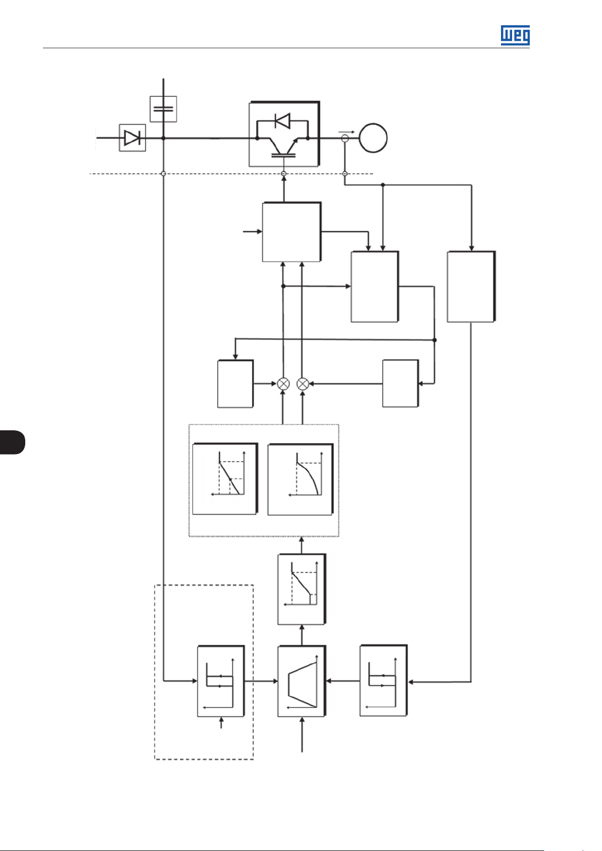
V/f Scalar Control
Power
supply
o
I
MI
3φ
sh
i
P004
d
U
Direction
of rotation
or
P202 = 0 (Control V/f)
P202 = 1 (Quadratic V/f)
P137
9
CURVE V/f
V
P202 = 0 (V/f)
P142
P14 3
P136
PWM
W
, i
V
i
o
Calculation of I
P007
m
PWM
sh
i
modulation
space vector
Angle,
sextant
m
P002
o
f
a
a
I
Calculation of I
P003
o
lxR
m
+
+
f
P14 5
P146
P202 = 1
(QUADRATIC V/f)
slip
f
+
+
P138
f
P14 5
V
P142
P136
I
9-2 | CFW300
P133
P134
d
U
t
o
I
Zero
d
U
DC Link Regulation
P151
P100-P104
P135
limitation
P151
f*
Output current
Figure 9.1: Block diagram of V/f scale control
Page 65

V/f Scalar Control
9.1 PARAMETERIZATION OF THE V/f SCALAR CONTROL
The scalar control is the inverter factory default control mode for its popularity and because it meets most
applications of the market. However, parameter P202 allows the selection of other options for the control mode,
as per Chapter 8 AVAILABLE MOTOR CONTROL TYPES on page 8-1.
The V/f curve is completely adjustable in four different points as shown in Figure 9.2 on page 9-3, although the
factory default set a curve pre-adjusted for motors 50 Hz or 60 Hz, as options for P204. This format, point P0
defines the amplitude applied at 0 Hz, while P2 defines the rated amplitude and frequency and beginning of field
weakening. Intermediate points P1 allow the setting of the curve for a non-linear relationship between torque and
frequency, for instance, in fans where the load torque is quadratic in relation to the frequency. The field weakening
region is determined between P2 and P3, where the amplitude is maintained in 100 %.
Output
voltage (%)
P142
P14 3
P136
P
2
P
1
P
0
Figure 9.2: Curve V/f
P
P134P14 5P14 6
3
Output
frequency (Hz)
The factory default setting of the CFW300 defines a linear relation of the torque with the frequency by means of
three points (P0, P1 and P2).
The points P0[P136, 0 Hz], P1[P143, P146], P2[P142, P145] and P3[100 %, P134] can be set so that the voltage and
frequency relation imposed to the output approximates the ideal curve for the load. Therefore, for loads in which
the torque behavior is quadratic in relation to the frequency, such as in centrifugal pumps and fans, the points
of the curve can be set or the Quadratic V/f control mode can be used so as to save energy. This Quadratic V/f
curve is presented in Figure 9.3 on page 9-3.
Output
voltage (%)
9
P142
P136
P134P14 5
Figure 9.3: Quadratic V/f Curve
Output
frequency (Hz)
NOTE!
In frequencies below 0.1 Hz, the output PWM pulses are cut, except when the inverter is in DC
Braking mode.
CFW300 | 9-3
Page 66

V/f Scalar Control
P136 - Manual Torque Boost
Adjustable
Range:
Properties:
0.0 to 30.0 % Factory
Setting:
V/f
5.0 %
Description:
It actuates at low speeds, that is, in the range 0 to P146 (V/f) or 0 to P145 (Quadratic V/f), increasing the inverter
output voltage so as to compensate the voltage drop in the motor stator resistance in order to keep the torque
constant.
The optimum setting is the smallest value of P136 which allows the motor satisfactory start. A value greater
than necessary will excessively increase the motor current at low speeds, which may lead the inverter to a fault
condition (F051 or F070) or alarm condition (A046 or A050), as well as motor overheating. Figure 9.4 on page
9-4 and Figure 9.5 on page 9-4 show the actuation regions of the Torque Boost for the V/f and Quadratic
V/f mode, respectively.
Output
voltage (%)
P142
P14 3
P
2
P
1
P
3
P136
P
0
9
Figure 9.4: Torque boost region for V/f control mode
Output
voltage (%)
P142
P136
Figure 9.5: Torque boost region for quadratic V/f control mode
P134P14 5P14 6
P134P14 5
Output
frequency (Hz)
Output
frequency (Hz)
9-4 | CFW300
Page 67

P142 - Maximum Output Voltage
P143 - Intermediate Output Voltage
V/f Scalar Control
Adjustable
Range:
Properties:
Description:
These parameters allow adjusting the inverter V/f curve together with its orderly pairs P145 and P146.
0.0 to 100.0 % Factory
Setting:
cfg, V/f
P142 = 100.0 %
P143 = 50.0 %
P145 - Field Weakening Start Frequency
P146 - Intermediate Output Frequency
Adjustable
Range:
Properties:
Description:
These parameters allow adjusting the inverter V/f curve together with its orderly pairs P142 and P143.
The V/f curve can be adjusted in applications where the motor rated voltage is smaller than the power supply
voltage, for example, a power supply of 220 V with motor of 200 V.
0.0 to 400.0 Hz Factory
Setting:
cfg, V/f
P145 = 60.0
(50.0) Hz
P146 = 30.0
(25.0) Hz
The adjustment of the V/f curve is necessary when the motor has a frequency different from 50 Hz or 60 Hz,
or when a quadratic approximation is desired for energy saving in centrifugal pumps and fans, or in special
applications: when a transformer is used between the inverter and the motor or the inverter is used as a power
supply.
P137 - Automatic Torque Boost
Adjustable
Range:
Properties:
Description:
The automatic torque boost compensates the voltage drop in the stator resistance because of active current.
Look at Figure 9.1 on page 9-2, where variable m
modulation index defined by V/f curve.
P137 actuates similarly to P136, but the value set is applied proportionally to the output active current in relation
to the maximum current (2 x P295).
The setting criteria of P137 are the same as those of P136, that is, set the value as low as possible for the motor
start and operation at low frequencies, because values above those increase the losses, heating and overload
of the motor and inverter.
0.0 to 30.0 % Factory
Setting:
V/f
corresponds to the automatic torque boost action on the
IxR
0.0 %
9
The block diagram of Figure 9.6 on page 9-6 shows the automatic compensation action IxR responsible for
the increment of the voltage in the ramp output according to the increase of the active current.
CFW300 | 9-5
Page 68

V/f Scalar Control
P007
Voltage
applied on
the motor
Output
active
current
Frequency reference
P139
Figure 9.6: Block diagram of the automatic torque boost
I x R
P136
I x R
automatic
P137
P138 - Slip Compensation
Adjustable
Range:
Properties:
Description:
Parameter P138 is used in the motor slip compensation function, when set for positive values. In this case, it
compensates the speed drop due to the application of load on the shaft and, consequently, the slip. Thus, it
increments the output frequency (Δf) considering the increase of the motor active current, as shown in Figure
9.7 on page 9-6. In Figure 9.1 on page 9-2 this compensation is represented in the variable f
The setting in P138 allows regulating with good accuracy the slip compensation by moving the operation
point on the V/f curve, as shown in Figure 9.7 on page 9-6. Once P138 is set, the inverter is able to keep the
frequency constant even with load variations.
9
Negative values are used in special applications where you wish to reduce the output frequency considering
the increase of the motor current.
-10.0 to 10.0 % Factory
Setting:
V/f
Slip
0.0 %
.
Eg.: load distribution in motors driven in parallel.
Output
voltage (%)
P142
P14 3
P136
Figure 9.7: Slip compensation in an operation point of the standar V/f curve
Δf
P14 6
P134P14 5
Output
frequency(Hz)
9-6 | CFW300
Page 69
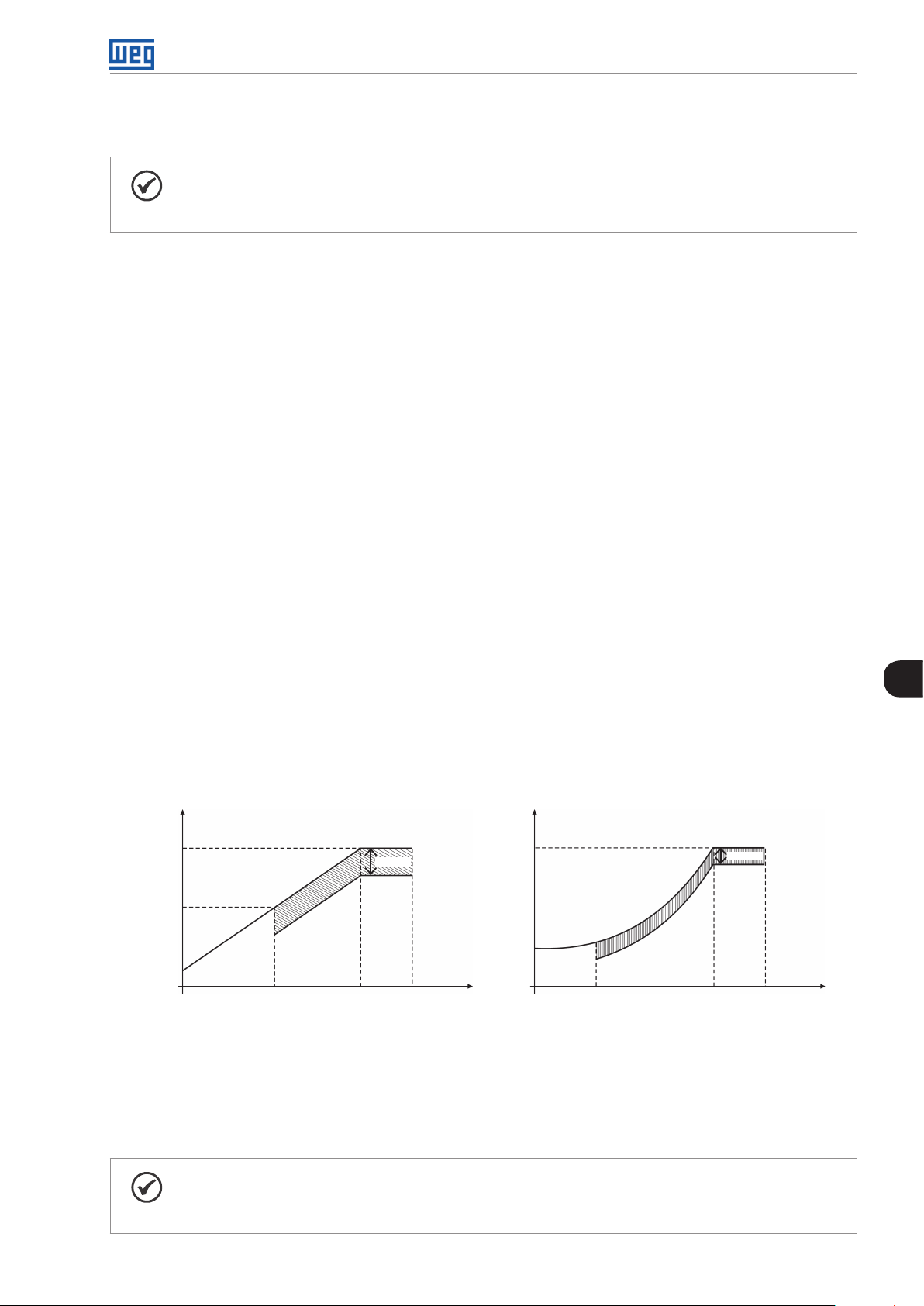
V/f Scalar Control
9.2 START-UP IN V/f MODE
NOTE!
Read chapter 3 Installation and Connection of the CFW300 user manual before installing, energizing
or operating the inverter.
Sequence for installation, verification, power up and start-up.
1. Install the inverter: according to chapter 3 Installation and Connection of the user’s manual, making all the
power and control connections.
2. Prepare and power up the inverter according to section 3.2 Electrical Installation of the user’s manual of the
CFW300.
3. Load the factory default with P204 = 5 (60 Hz) or P204 = 6 (50 Hz), according to the input rated frequency
(power supply) of the inverter used.
4. In order to set a V/f curve different from the default, set the V/f curve using parameters P136 to P146.
5. Setting of specific parameters and functions for the application: program the digital and analog inputs and
outputs, HMI keys, etc., according to the application requirements.
9.3 ENERGY SAVING
The efficiency of a machine is defined as being the ratio between the output mechanical power and the input
electrical power. Remember that the mechanical power is the product between torque and rotor speed, and that
the input electric power is the sum of the output mechanical power and the motor losses.
In the case of the three-phase induction motor, the optimized efficiency is achieved with ¾ of the rated load. In
the region below this point, the Energy Saving function has its best performance.
The Energy Saving function acts directly on the voltage applied on the inverter output; thus, the flux relationship
delivered to the motor is changed so as to reduce the motor losses and enhance the efficiency, consequently
reducing consumption and noise.
Output
voltage (%)
P142
P591 (%V)
P590 P590P14 5 P14 5
(a) Voltage in V/f (b) Voltage in quadratic V/f
Figure 9.8: (a) and (b) Example of voltage behavior in V/f and quadratic V/f
frequency (Hz)
voltage (%)
Output
Output
P142
P591 (%V)
P134 Output
frequency (Hz)
9
The function will be active when the motor load is below the maximum value (P588) and the frequency is above
the minimum value (P590). In addition, in order to prevent the stalling of the motor, the applied voltage is limited to
a minimum acceptable value (P589). The parameter group presented in the sequence defines the characteristics
necessary for the energy saving function.
NOTE!
The use of the energy saving function is recommended in quadratic torque applications (blowers,
fans, pumps and compressors).
CFW300 | 9-7
Page 70

V/f Scalar Control
P401 - Motor Rated Current
Adjustable
Range:
Properties:
Description:
In order to obtain the proper operation of the energy saving function, the motor current value must be correctly
set, according to the information on the motor nameplate.
0.0 to 40.0 A Factory
Setting:
cfg
1.0 x I
nom
P407 – Motor Rated Power Factor
Adjustable
Range:
Properties:
Description:
Setting of the motor rated power factor. In order to obtain the proper operation of the energy saving function,
the motor power factor must be correctly set, according to the information on the motor nameplate.
NOTE!
With the motor nameplate data and for applications with constant torque, the motor optimum efficiency
is normally obtained with the energy saving function active. In some cases, the output current may
increase, and then it is necessary to gradually reduce the value of this parameter to the point in which
the current value remains equal to or below the current value obtained with the function disabled.
0.50 to 0.99 Factory
Setting:
cfg, V/f, VVW
0.80
9
For information regarding the actuation of P407 in the VVW control mode, refer to Chapter 10 VVW VECTOR
CONTROL on page 10-1.
P588 – Energy Saving Maximum Torque Adjustable
Adjustable
Range:
Properties:
Description:
This parameter defines the torque value to activate the operation of the energy saving function.
Setting this parameter to 0 % disables the function.
It is recommended to set this parameter to 60 %, but it has to be set according the application requirements.
0 to 85 % Factory
Setting:
cfg, V/f
0 %
P589 – Level of Minimum Applied Voltage
Adjustable
Range:
Properties:
Description:
This parameter defines the minimum voltage value that will be applied to the motor when the energy saving
function is active. This minimum value is relative to the voltage imposed by the V/f curve for a certain speed.
40 to 80 % Factory
Setting:
cfg, V/f
40 %
9-8 | CFW300
Page 71

P590 – Energy Saving Minimum Frequency
V/f Scalar Control
Adjustable
Range:
Properties:
Description:
This parameter defines the minimum speed value at which the energy saving function will remain active.
The hysteresis for the minimum speed level is of 2 Hz.
12.0 to 400.0 Hz Factory
Setting:
cfg, V/f
20 Hz
P591 – Energy Saving Hysteresis Adjustable
Adjustable
Range:
Properties:
Description:
Hysteresis used to activate and deactivate the energy saving function.
If the function is active and the output current oscillates, it is necessary to increase the hysteresis value.
NOTE!
It is not possible to set those parameters, while the motor is spinning.
0 to 30 % Factory
Setting:
cfg, V/f
10 %
9
CFW300 | 9-9
Page 72

V/f Scalar Control
9
9-10 | CFW300
Page 73

V VW Vector Control
10 VVW VECTOR CONTROL
The V VW vector control mode (Voltage Vector WEG) uses a control method with a much higher performance
than the V/f control because of the load torque estimation and of the control of the magnetic flux in the air gap, as
per scheme of Figure 10.1 on page 10-2. In this control strategy, losses, efficiency, rated slip and power factor of
the motor are considered in order to improve the control performance.
The main advantage compared to the V/f control is the best frequency regulation with greater torque capacity at
low speeds (frequencies below 5 Hz), allowing a relevant improvement in the drive performance in permanent
duty. Besides, the V VW control has a quick and simple setting and it is suitable for most medium-performance
applications in the control of three-phase induction motor.
By just measuring the output current, the VV W control instantly obtains the motor torque and slip. Thus, the
VV W actuates in the output voltage compensation and slip compensation. Therefore, the VV W controller action
replaces the classical V/f functions in P137 and P138, but with a calculation model much more sophisticated and
accurate, meeting several load conditions or operation points of the application.
In order to achieve a good frequency regulation in permanent duty with a good operation of the V VW control, the
parameter setting in the range P399 to P407, and the stator resistance in P409 are essential for the good operation
of the VV W control. These parameters can be easily obtained on the motor nameplate.
10
CFW300 | 10-1
Page 74

V VW Vector Control
Power
supply
P004
d
U
Direction
o
I
MI
3φ
sh
i
PWM
W
, i
V
sh
of rotation
vector
modulation
PWM space
o
f
Angle,
sextant
P295
i
a
a
I
P295
i
o
P003
o
I
10
m P007
d
U
compensation
Output voltage
Calculation of I
m
Calculation of I
m*
o
I
a
I
P202 = 5 (V VW Control)
P40 9, P178
P400, P40 3, P401, P407,
Flux control
P002
o
f
slip
f
r
f
t
Filter
P14 0
o
f
slip
of f
Calculation
, S
/T
T
a
o
o
I
I
f
R
R
L
m
Torq u e
estimation
d
U
P403
P402,P403
P401,P4 09,
P404,P399,
10-2 | CFW300
P133
P134
controler
Current limitation
d
U
DC Link Regulation
d
U
P151
t
o
I
Zero
P135
P100-P104
f*
Figure 10.1: VV W control flow
Page 75
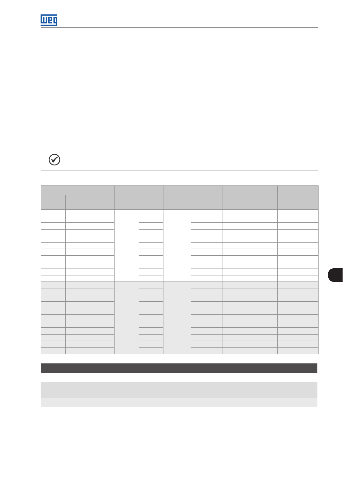
V VW Vector Control
10 .1 VVW VECTOR CONTROL PARAMETERIZATION
The V VW control mode is selected by parameter P202, control mode selection, as described in Chapter 8
AVAILABLE MOTOR CONTROL TYPES on page 8-1.
Opposite to the V/f scalar control, the VV W control requires a series of data from the motor nameplate and a
self-tuning for its proper operation. Besides, it is recommended that the driven motor match the inverter, that is,
the motor and inverter power be as close as possible.
Below are described the parameters to configure the V VW vector control setting. This data is easily obtained on
WEG standard motor nameplates, however in older motors or motors made by other manufacturers, the data
may not be readily available. In those cases, it is recommended first contact the motor manufacturer, measure or
calculate the desired parameter. As a last resort, the user always can make a relationship with Table 10.1 on page
10-3 and use the equivalent or approximate WEG standard motor parameter.
NOTE!
The correct setting of the parameters directly contributes to the V VW control performance.
Table 10 .1: Characteristics of IV pole WEG standard motors
Power [P404]
(HP) (kW)
0.16 0 .12 63
0.25 0 .18 63 1.12 172 0 64.0 0.66 14.87
0.33 0.25 63 1.42 1720 6 7. 0 0.69 10.6 3
0.50 0.37 71 2.07 1720 68.0 0.69 7.37
0.75 0.55 71 2.90 1720 71.0 0.70 3.97
1.0 0 0.75 80 3.08 1730 78.0 0.82 4.13
1.5 0 1.10 80 4.78 170 0 72.7 0.83 2.78
2.00 1.50 90S 6 .47 172 0 80.0 0.76 1. 5 5
3.00 2.20 90L 8.57 1710 79.3 0.85 0.99
4.00 3.00 100L 11.6 1730 82.7 0.82 0.65
5.00 3.70 100 L 13.8 173 0 84.6 0.83 0.49
0.16 0 .12 63
0.25 0 .18 63 1.05 1360 58.0 0.74 20.31
0.33 0.25 71 1.4 1310 59.0 0.76 14. 32
0.50 0.37 71 1.97 1320 62.0 0.76 7.2 7
0.75 0.55 80 2.48 1410 68.0 0.82 5.78
1.0 0 0.75 80 3.23 139 5 72.0 0.81 4.28
1.5 0 1.10 90S 4.54 1420 7 7.0 0.79 2.58
2.00 1.50 90L 5.81 1410 79.0 0.82 1.69
3.00 2.20 10 0 L 8.26 1410 81. 5 0.82 0.98
4.00 3.00 100L 11. 3 140 0 82.6 0.81 0.58
5.00 3.70 112M 14 .2 144 0 85.0 0.83 0.43
Frame
size
Volt ag e
[P400]
(V)
220
230
Current
[P4 01]
(A)
0.85
0.73
Frequency
[P403]
(Hz)
60
50
Speed
[P402]
(rpm)
172 0 56.0 0.66 21.77
1375 57.0 0.72 30.62
Efficiency
[P399]
(%)
Power
Factor
Stator
Resistance
[P409]
(Ω)
10
P178 - Rated Flux
Adjustable
Range:
Properties:
Description:
It defines the desired flux in the motor air gap in percentage (%) of the rated flux. In general, it is not necessary
to modify the value of P178 of the standard value of 100 %. However, some specific situations may use values
slightly above to increase the torque, or below to reduce the energy consumption.
50.0 to 150.0 % Factory
Setting:
VV W
100.0 %
CFW300 | 10-3
Page 76

V VW Vector Control
P399 - Motor Rated Efficiency
Adjustable
Range:
Properties:
50.0 to 99.9 % Factory
Setting:
cfg, VV W
67. 0 %
Description:
This parameter is important for the precise operation of the V VW control. A misconfiguration will cause incorrect
calculation of the slip compensation, reducing the performance of the speed control.
P400 - Motor Rated Voltage
Adjustable
Range:
Properties:
Description:
Set according to the data on the motor nameplate and the wire connection on the motor terminal box. This
value cannot be above the rated voltage value set in P296 (power supply rated voltage).
0 to 240 V Factory
Setting:
cfg, VV W
Tabl e 10. 2 : Default setting of P400 according to the identified inverter model
P296 P145 (H z) P400 (V)
0 Reserved Reserved
1
2
50.0 230
60.0 220
50.0 230
60.0 220
According
inverter
model
10
For further information on model identification, refer to Table 6.3 on page 6-2 of Chapter 6 IDENTIFICATION
OF THE INVERTER MODEL AND ACCESSORIES on page 6-1.
P401 - Motor Rated Current
Adjustable
Range:
Properties:
0.0 to 40.0 A Factory
Setting:
cfg
1.0 x I
nom
P402 - Motor Rated Speed
Adjustable
Range:
Properties:
0 to 30000 rpm Factory
Setting:
cfg
172 0
(1310) rpm
P403 - Motor Rated Frequency
Adjustable
Range:
Properties:
0 to 400 Hz Factory
Setting:
cfg
60 Hz
(50 Hz)
10-4 | CFW300
Page 77

P404 - Motor Rated Power
V VW Vector Control
Adjustable
Range:
Properties:
Description:
The setting of parameters P401, P402, P403 and P404 must be according to the data on the nameplate of the
motor used, taking into account the motor voltage.
The setting of parameter P402 via HMI for values above 9999 rpm is performed from 10.00 to 30.00 rpm (x 1000).
0 = 0.16 HP (0.12 kW)
1 = 0.25 HP (0.18 kW)
2 = 0.33 HP (0.25 kW)
3 = 0.50 HP (0.37 kW)
4 = 0.75 HP (0.55 kW)
5 = 1.00 HP (0.75 kW)
6 = 1.50 HP (1.10 kW)
7 = 2.00 HP (1.50 kW)
8 = 3.00 HP (2.20 kW)
9 = 4.00 HP (3.00 kW)
10 = 5.00 HP (3.70 kW4)
cfg, V V W
Factory
Setting:
According
inverter
model
P405 - Encoder Pulse Number
Adjustable
Range:
Properties:
32 to 9999 ppr Factory
Setting:
cfg
1024
Description:
It sets the number of pulses per revolution (ppr) of the incremental encoder. This parameter influences the
indication of the speed parameters (P038) and pulse counter (P039) of the encoder.
NOTE!
Parameter P405 is only visible on the HMI if the CFW300-IOAENC expansion module is connected
to the inverter.
P407 - Motor Rated Power Factor
Adjustable
Range:
Properties:
Description:
The setting of this parameter must be according to the data on the nameplate of the motor used, taking into
account the motor voltage.
0.50 to 0.99 Factory
Setting:
cfg, VV W
0.69
P408 - Self-Tuning
Adjustable
Range:
Properties:
0 = No
1 = Yes
cfg, VVW
Factory
Setting:
0
10
CFW300 | 10-5
Page 78

V VW Vector Control
Description:
Parameter P408 in 1 activates the self-tuning of the VVW mode, where the motor stator resistance is measured.
The self-tuning can only be activated via HMI, and it can be interrupted at any time with the key.
During the self-tuning, the bar graph shows the progress of the operation and the motor remains still, because
a DC signal is sent to measure the stator resistance.
If the estimated value of the motor stator resistance is too high for the inverter used (for example: motor not
connected or motor too small for the inverter) the inverter indicates fault F033.
At the end of the self-tuning process, the measured motor stator resistance is saved in P409.
P409 - Stator Resistance
10
Adjustable
Range:
Properties:
Description:
Motor phase stator resistance in ohms (Ω), assuming a star (Y) motor connection.
If the value adjusted in P409 is too high or too low for the inverter used, the inverter indicates fault F033. In
order to exit this condition, just perform a reset by using the I/O key. In this case, P409 will be loaded with the
factory default value.
0.01 to 99.99 Ω Factory
Setting:
cfg, VV W
According
inverter
model
10.2 START-UP IN V VW MODE
NOTE!
Read chapter 3 Installation and Connection of the user’s manual before installing, powering up or
operating the inverter.
Sequence for installation, verification, power up and start-up:
1. Install the inverter: according to chapter 3 Installation and Connection of the user’s manual, making all the
power and control connections.
2. Prepare and power up the inverter: according to section 3.2 Electrical Installation of the user’s manual.
3. Load the correct factory default in P204: based on the motor rated frequency (set P204 = 5 for 60 Hz
motors and P204 = 6 for 50 Hz motors).
4. Adjustment of parameters and specific functions for the application: program the digital and analog
inputs and outputs, HMI keys, etc., according to the application requirements.
5. Activation of the V VW control: set P202 = 5 and parameters P399, P400, P401, P402, P403, P404 and
P407 according to the motor nameplate. Also set the value of P409. If some of those data are not available,
enter the approximate value by calculation or by similarity with WEG standard motor - see Table 10.1 on page
10-3.
6. Self-Tuning of the V V W control: the self-tuning is activated by setting P408 = 1. In this process, the inverter
applies DC to the motor to measure the stator resistance, while the HMI bar graph shows the progress of the
self-tuning. The self-tuning process can be interrupted at any time by pressing the key.
10-6 | CFW300
Page 79

V VW Vector Control
7. End of the Self-Tuning: at end of the self-tuning, the HMI returns to the browsing menu, the bar displays the
parameter programmed by P207 again and the stator resistance measured is stored in P409. On the other
hand, if the self-tuning fails, the inverter will indicate a fault. The most common fault in this case is F033, which
indicates error in the estimated stator resistance. Refer to Chapter 14 FAULTS AND ALARMS on page 14-1.
For better visualization of the start-up in the V VW mode, check Figure 10.2 on page 10-7, below:
Seq Action/Indication on the Display Seq Action/Indication on the Display
1
Monitoring mode
Press this key to enter the first level of the setting mode
3 4
Press the key to change the content of “P202 -Control
Type” to P202 = 5 (V V W). Use the key
5 6
If necessary, change the content of “P399 - Motor Rated
Efficiency” according to data on the nameplate
Press the key for the next parameter
7 8
If necessary, change the content of “P401 - Motor Rated
Current”
Press the key for the next parameter
9 10
If necessary, change the content of “P403 - Motor Rated
Frequency”
Press the key for the next parameter
2
Press the keys or until selecting parameter P202
Press the key to save the change of P202
Use the keys until selecting parameter P399
If necessary, change the content of “P400 - Motor Rated
Voltage”
Press the key for the next parameter
If necessary, change the content of “P402 - Motor Rated
Speed”
Press the key for the next parameter
If necessary, change the content of “P404 - Motor Rated
Output”
Press the key for the next parameter
10
11 12
If necessary, change the content of “P407 - Motor Rated
Power Factor”
Press the key for the next parameter
13 14
During the self-tuning, the HMI will show “Auto”, and the
bar will indicate the operation progress
15
If necessary, change the content of “P409 - Stator
Resistance”
Figure 10.2: Start-up of the V VW mode
If necessar y to make the self-tuning, change the value of
P408 to “I”
When the self-tuning is completed, it will return to the (comp)
Initialization Mode
CFW300 | 10-7
Page 80

V VW Vector Control
10
10-8 | CFW300
Page 81

Functions Common to All the Control Modes
11 FUNCTIONS COMMON TO ALL THE CONTROL MODES
This chapter describes the functions common to the inverter V/f and VV W control modes, but which interferes
in the drive performance.
11.1 RAMPS
The inverter ramp functions allow the motor to accelerate or decelerate faster or slower. They are adjusted by
parameters that define the linear acceleration time between zero and the maximum frequency (P134) and the time
for a linear deceleration from the maximum frequency zero.
In the CFW300, three ramps with different functions were implemented:
st
1
Ramp - standard for most functions.
nd
2
Ramp - it may be activated by the user, according to the drive requirement, by means of the inverter
command word or by a digital input.
Emergency Ramp - it is used for the inverter internal protection functions, such as: current limitation, DC link
regulation, etc. The Emergency Ramp has priority over the other ramps.
NOTE!
The setting with too short ramp time may cause overcurrent in the output (F070), undervoltage (F021)
or overvoltage (F022) of the DC link.
P100 - Acceleration Time
Adjustable
Range:
Properties:
Description:
Acceleration time from zero to maximum frequency (P134).
0.1 to 999.9 s Factory
P101 - Deceleration Time
Adjustable
Range:
Properties:
Description:
Deceleration time from maximum frequency (P134) to zero.
0.1 to 999.9 s Factory
5.0 s
Setting:
11
10.0 s
Setting:
P102 - Acceleration Time 2nd Ramp
Adjustable
Range:
Properties:
Description:
Acceleration time from zero to maximum frequency (P134) when the 2nd Ramp is active.
0.1 to 999.9 s Factory
5.0 s
Setting:
CFW300 | 11-1
Page 82

Functions Common to All the Control Modes
P103 - Deceleration Time 2nd Ramp
Adjustable
Range:
0.1 to 999.9 s Factory
Setting:
Properties:
Description:
Deceleration time from maximum frequency (P134) to zero when the 2nd Ramp is active.
P106 - Emergency Ramp Acceleration Time
Adjustable
Range:
Properties:
Description:
Acceleration time from zero to maximum frequency (P134) when the emergency ramp is active.
0.1 to 999.9 s Factory
Setting:
P107 - Emergency Ramp Deceleration Time
Adjustable
Range:
Properties:
0.1 to 999.9 s Factory
Setting:
10.0 s
5.0 s
5.0 s
11
Description:
Deceleration time from maximum frequency (P134) to zero when the emergency ramp is active.
P104 - S Ramp
Adjustable
Range:
Properties:
Description:
This parameter allows the inverter acceleration and deceleration ramps to have a non-linear profile, similar to an
"S", aiming at reducing the mechanical shocks on the load, as shown in Figure 11.1 on page 11-2.
0 = Inactive
1 = Active
cfg
Output
frequency
Linear ramp
Ramp S
t (s)
Factory
Setting:
0
11-2 | CFW300
Acceleration time
(P100/P102)
Deceleration time
(P101/P103)
Figure 11.1: S or Linear ramp
Page 83

P105 - 1st / 2nd Ramp Selection
Functions Common to All the Control Modes
Adjustable
Range:
0 = 1st Ramp
1 = 2nd Ramp
Factory
Setting:
0
2 = DIx
3 = Serial/USB
4 = Reserved
5 = CO/DN/DP
6 = SoftPLC
Properties:
Description:
It defines the origin source of the command to select between the first and second Ramp.
Note: Parameter P680 (Logical Status) indicates if the 2nd Ramp is active or not. For further information on this
parameter, refer to Section 7.3 CONTROL WORD AND INVERTER STATUS on page 7-11.
11. 2 DC LINK VOLTAGE AND OUTPUT CURRENT LIMITATION
The DC link voltage and output current limitation are protection functions of the inverter which act on the ramp
control, aiming at containing the rise of voltage on the DC link and of the output current. In this way, the following of
the reference by the ramp is blocked and the output frequency follows the Emergency Ramp for a preset safety
value.
When the DC link voltage is too high, the inverter may freeze the deceleration ramp. On the other hand, when
the output current is too high, the inverter may decelerate or freeze the acceleration ramp in order to reduce this
current. Those actions prevent the occurrence of faults F022 and F070, respectively.
Both protections normally occur at different moments of the inverter operation, but in case of occurrence at the
same time, by definition, the DC link limitation has higher priority than the output current limitation.
The voltage limitation on the DC link during braking actuates limiting the braking power and torque, so as to prevent
the shutting down of the inverter for overvoltage (F022). This situation often occurs when a load with high moment
of inertia is decelerated or when short deceleration time is programmed.
11. 2 .1 DC Link Voltage Limitation by "Ramp Hold" P150 = 0 or 2
It has effect during deceleration only.
Actuation: when the DC link voltage reaches the level set in P151, a command is sent to the "ramp" block, which
inhibits the motor frequency variation according to Figure 9.1 on page 9-2 and Figure 10.1 on page 10-2.
Use recommended in the drive of loads with high moment of inertia referred to the motor shaft or loads that
require short deceleration ramps.
11.2.2 DC Link Voltage Limitation by "Accelerate Ramp" P150 = 1 or 3
It has effect in any situation, regardless the motor frequency condition: accelerating, decelerating or constant
frequency.
Actuation: when the DC link voltage reaches the level set in P151, a command is sent to the "ramp" block to
accelerate the motor.
11
Use recommended for the drive of loads that require braking torques at constant frequency in the inverter
output. For example, the drive of loads with eccentric shaft as in sucker rod pumps; another application is the
handling of loads with balance like in the translation in overhead cranes.
CFW300 | 11-3
Page 84

Functions Common to All the Control Modes
P149 - Compensation of the DC Link Voltage
Adjustable
Range:
Properties:
0 = Inactive
1 = Active
cfg
Factory
Setting:
0
Description:
It enables the use of Compensation of the DC link.
P150 - Type DC V/f Link Regulator
Adjustable
Range:
Properties:
Description:
P150 configures the behavior of the ramp for the limitation functions of the DC Link Voltage and Current Limitation.
In those cases, the ramp ignores the reference and takes an action of accelerating (accel), decelerating (decel)
or freezing (hold) the normal path of the ramp. That occurs because of the limit pre-defined in P151 and P135
for the DC Link (Ud) Limitation and for Current (LC) Limitation, respectively.
0 = Hold_Ud and Decel_LC
1 = Accel_Ud and Decel_LC
2 = Hold_Ud and Hold_LC
3 = Accel_Ud and Hold_LC
cfg
Factory
Setting:
0
P151 - DC Link Regulation Level
11
Adjustable
Range:
348 to 460 V Factory
Setting:
According to
Table 11.1 on
page 11-4
Properties:
Description:
Voltage level to activate the DC link voltage regulation.
Tab l e 11.1: Actuation Level of the Voltage Regulation
Input Voltage P151 Actuation Band P151 Factory Default
100 to 127 Vac 391 to 460 Vdc 395 Vdc
200 to 240 Vac 348 to 410 Vdc 365 Vdc
Figure 11.2 on page 11-4 shows the block diagram of the actuation of the limitation. Figure 11.3 on page 11-5
and Figure 11.4 on page 11-5 show the example chart.
Ramp
P100-P104
P001
Reference
hold
Output frequency
t
P002
11-4 | CFW300
P004
error
+
-
P151
Figure 11.2: Block diagram DC Link voltage limitation
≥ 0
Page 85

Functions Common to All the Control Modes
DC Link voltage (P004)
U
d
F022-overvoltage
P151
Ud rated
Output
frequency
Figure 11.3: Example graph of DC Link voltage limitation - Ramp Hold
DC Link voltage (P004)
U
d
P151
Ud rated
DC Link regulation
Time
Time
F022-overvoltage
DC Link regulation
Time
Output
frequency
Time
Figure 11.4: Example graph of the DC Link voltage limitation - Accelerate Ramp
Like in the DC Link voltage regulation, the output current regulation also has two operating modes: "Ramp Holding"
(P150 = 2 or 3) and "Decelerate Ramp" (P150 = 0 or 1). Both actuate limiting the torque and power delivered to the
motor, so as to prevent the shutting down of the inverter by overcurrent (F070). This situation often occurs when
a load with high moment of inertia is accelerated or when short acceleration time is programmed.
11. 2 .3 Output Current Limitation by "Ramp Hold" P150 = 2 or 3
It prevents the motor from collapsing during torque overload in the acceleration or deceleration.
Actuation: if the motor current exceeds the value set in P135 during acceleration or deceleration, the frequency
will not be incremented (acceleration) or decremented (deceleration). When the motor current reaches a value
below P135 the motor accelerates or decelerates again. Refer to Figure 11.5 on page 11-6.
It has a faster action than the "Decelerate Ramp" mode.
11
It acts in the motorization and regeneration modes.
CFW300 | 11-5
Page 86

Functions Common to All the Control Modes
11. 2 .4 Current Limitation Type "Decelerate Ramp" P150 = 0 or 1
It prevents the motor from collapsing during torque overload in the acceleration or constant frequency.
Actuation: if the motor current exceeds the value set in P135, a null value is forced for the frequency ramp input
forcing the motor deceleration. When the motor current reaches a value below P135 the motor accelerates
again. Look at Figure 11.5 on page 11-6.
P135 - Maximum Output Current
Adjustable
Range:
0.0 to 40.0 A Factory
Setting:
1.5 x I
nom
Properties:
Description:
Current level to activate the current limitation for the Ramp Hold and Decelerate Ramp modes, as per Figure
11.5 on page 11-6 (a) and (b), respectively. In order to disable the current limitation, you must set parameter
P135 > 1.9 x I
nom
.
Motor current
Output
frequency
Ramp
acceleration
(P100)
During
Acceleration
Motor current
P135P135
Output
frequency
Ramp
deceleration
(P101)
Time
(a) "Ramp Hold"
Time
Time
Deceleration
11
Motor current
P135
Time
Output
frequency
It decelerates
by emergency
ramp
Time
(b) "Ramp Deceleration"
Figure 11.5: (a) and (b) Actuation modes of current limitation via P135
11-6 | CFW300
Page 87

Functions Common to All the Control Modes
11. 3 FLYING START / RIDE-THROUGH
The Flying Start function allows driving a motor that is in free running, accelerating it from the rotation in which it
is. The Ride-Through function allows recovering the inverter, with no locking by undervoltage, when there is an
instant drop in the power supply.
Both functions assume the special case in which the motor is running in the same direction and at a frequency
close to the frequency reference, thus, by immediately applying the frequency reference to the output and increasing
the output voltage in ramp, the slip and the starting torque are minimized.
P320 - Flying Start (FS) / Ride Through (RT)
Adjustable
Range:
Properties:
Description:
Parameter P320 selects the use of the Flying Start and Ride-Through functions. More details in the following
sections.
0 = Inactive
1 = Flying Start
2 = Flying Start / Ride-Through
3 = Ride-Through
cfg
Factory
Setting:
0
P331 - Voltage Ramp for FS and RT
Adjustable
Range:
Properties:
Description:
This parameter determines the rising time of the output voltage during the execution of the Flying Start and
Ride-Through functions.
0.2 to 60.0 s Factory
Setting:
2.0 s
P332 - Dead Time
Adjustable
Range:
Properties:
0.1 to 10.0 s Factory
Setting:
1.0 s
11
Description:
Parameter P332 sets the minimum time the VSD will wait until driving the motor again with the Ride Through
function, which is necessary to demagnetize the motor.
11. 3.1 Flying Start Function
In order to activate this function, just program P320 in 1 or 2; thus the inverter will impose a fixed frequency at
the start, defined by the frequency reference, and apply the voltage ramp defined in parameter P331. In this way,
the start current is reduced. On the other hand, if the motor is at rest, the frequency reference and the real frequency
of the motor are very different or the direction of rotation is inverted; the result in such cases may be worse than the
conventional start without Flying Start.
The Flying Start function is applied on loads with high inertia or systems that require start with the motor
spinning. Besides, the function may be deactivated dynamically by a digital input P263 to P266 programmed
for "24 = Disable Flying Start". In this way, the user may activate the function in a convenient way according to
the application.
CFW300 | 11-7
Page 88

Functions Common to All the Control Modes
11. 3. 2 Ride-Through Function
The Ride-Through function will disable the inverter output pulses (IGBT) as soon as the supply voltage reaches a
value below the undervoltage value. A fault due to undervoltage (F021) does not occur and the DC link voltage will
slowly drop until the supply voltage returns. In case it takes the supply voltage too long to return (over 2 seconds),
the inverter may indicate F021 (undervoltage on the DC link). If the supply voltage returns before, the inverter will
enable the pulses again, imposing the frequency reference instantly (like in the Flying Start function) and making a
voltage ramp with time defined by parameter P331. Refer to Figure 11.6 on page 11-8.
Return line
DC Link voltage
Level F021
11
dead
Enabled
P331
Output pulses
Output voltage
0 V
Output frequency
(P002)
0 Hz
t
> t
disab.
Disabled
Figure 11.6: Actuation of the Ride-Through function
The Ride-Through function allows recovering the inverter without locking by undervoltage F021 for momentary
power supply drops. The time interval accepted during a fault is at most two seconds.
11. 4 DC BRAKING
The DC Braking allows stopping the motor by applying direct current to it. The current applied at the DC Braking
is proportional to the braking torque and may be set in P302. It is set in percentage (%) of the inverter rated current
considering the motor of power compatible with the inverter.
P299 - DC Braking Time at Start
Adjustable
0.0 to 15.0 s Factory
Range:
Properties:
Description:
DC braking duration at the start.
11-8 | CFW300
0.0 s
Setting:
Page 89

Output frequency
DC braking
Stop
Figure 11.7: DC Braking actuation at start
P300 - DC Braking Time at Stop
Functions Common to All the Control Modes
Direct current
injection at start
Time
P299
P302
Time
Run
Adjustable
Range:
0.0 to 15.0 s Factory
Setting:
0.0 s
Properties:
Description:
DC Braking duration at the stop. Figure 11.8 on page 11-9 shows the braking behavior at the stop, where the
dead time for the de-magnetization of the motor can be observed. This time is proportional to the frequency at
the moment of the injection of direct current.
Injection of
Output
frequency
0 V
DIx - Run/Stop
DC current
P300
P301
Time Time
Open
(a) Run/Stop (b) General Enable
Figure 11.8: (a) and (b) Actuation of DC Braking
Output
frequency
Dead
time
0 V
DIx - General Enable
P300
Open
11
During the braking process, if the inverter is enabled, the braking is interrupted and the inverter will start
operating normally.
ATTENTION!
The DC Braking can continue acting even if the motor has already stopped. Be careful with the
thermal dimensioning of the motor for short-period cyclic braking.
CFW300 | 11-9
Page 90

Functions Common to All the Control Modes
P301 - Frequency to Begin DC Braking at Stop
Adjustable
Range:
Properties:
Description:
This parameter establishes the initial point to apply the DC Braking at the stop when the inverter is disabled by
ramp, as per Figure 11.8 on page 11-9.
0.0 to 400.0 Hz Factory
Setting:
3.0 Hz
P302 - Voltage Applied to the DC Braking
Adjustable
Range:
Properties:
Description:
This parameter sets the DC voltage (DC Braking torque) applied to the motor during the braking.
The setting must be done by gradually increasing the value of P302, which varies from 0.0 to 100.0 % of the
rated braking voltage, until the desired braking is obtained.
The rated braking voltage is the DC voltage value, which results in the rated current for the motor with power
matched to the inverter. Therefore, if the inverter has a power too much higher than the motor, the braking
torque will be too low. On the other hand, if the opposite is true, overcurrent may occur during the braking, as
well as overheating of the motor.
0.0 to 100.0 % Factory
Setting:
20.0 %
11
11. 5 SKIP FREQUENCY
This inverter function prevents the motor from operating permanently at frequency values in which, for example,
the mechanical system goes into resonance (causing excessive vibration or noises).
P303 - Skip Frequency 1
Adjustable
Range:
0.0 to 400.0 Hz Factory
Setting:
0.0 Hz
P304 - Skip Frequency 2
Adjustable
Range:
0.0 to 400.0 Hz Factory
Setting:
0.0 Hz
P306 - Skip Band
Adjustable
Range:
Properties:
0.0 to 25.0 Hz Factory
Setting:
0.0 Hz
Description:
The actuation of those parameters is done as presented in Figure 11.9 on page 11-11 below.
The passage by the skip frequency band (2 x P306) is done through acceleration/deceleration ramp.
The function does not operate correctly if two bands of "Skip Frequency" overlap.
11-10 | CFW300
Page 91

Output
frequency
Functions Common to All the Control Modes
P304
P303
Figure 11.9: Actuation of the skip frequency
2 x P306
P303
2 x P306
Reference
P304
11.6 FIRE MODE
The “Fire Mode” function is intended to make the frequency inverter continue to drive the motor even under
adverse conditions, inhibiting most faults generated by the frequency inverter. The “Fire Mode” is activated by
driving a digital input previously set to “Fire Mode” with logic level “0” at the input terminals. When the drive enters
the“Fire Mode”, the alarm “A211” will be generated on the HMI (keypad) and the status of the operation mode will
be updated in parameter P006.
DANGER!
“FIRE MODE” FUNCTION – RISK OF DEATH!
Notice that the CFW300 is only one of the components of the system, and it is configurable for
several functions that must be pre-established in the project.
Therefore, the full operation of the "Fire Mode" function, with the required safety, depends on the
specification in the project, as it also requires the compatibility with all the other components of
the system and the installation environment.
Ventilation systems that operate in life safety applications must be approved by the Fire Department
and/or another competent local public authority.
The activation of the “Fire Mode” function disables essential protection functions for the safety of
the CFW300 and of the system as a whole.
The non-interruption of the CFW300 operation due to the improper activation of the “Fire Mode”
function is critical, as it may cause injuries or even death, and damages to the CFW300, to the
other components of the system and to the environment where it is installed.
The operation in the “Fire Mode” function may, under certain circumstances, result in fire, as the
protection devices will be disabled.
Only qualified personnel from safety engineer departments must evaluate and activate the
equipment “Fire Mode” function.
It is essential to follow the aforementioned instructions before using the CFW300 in the "Fire
Mode" function.
Under no circumstance shall WEG take any liability for deaths, damages, compensations and/or losses
occurred due to the improper programming or operation of the CFW300 in the "Fire Mode" function.
IMPORTANT – RISK OF DEATH!
When activating the “Fire Mode” function, the user must be aware of the fact that the protection
functions of the CFW300 will be disabled, which may result in damages:
- To the inverter.
- To the components connected to it.
- To the environment where it is installed.
- To the people present in the place.
Therefore, the operator who activates the “Fire Mode” function takes full liability for the resulting risks.
The operation of the inverter with the “Fire Mode” function programmed voids the warranty of the
product.
The operation in this condition is internally registered by the CFW300, and it may be validated by an
engineer and occupational safety professional duly qualified by the manufacturer.
11
CFW300 | 11-11
Page 92

Functions Common to All the Control Modes
NOTE!
When activating the "Fire Mode" function, the user acknowledges that the protection functions of the
CFW300 are disabled, which may result in damages to the CFW300, to the components connected
to it, to the environment in which it is installed and to the people present in such environment.
Therefore, the user takes full liability for the resulting risks. The operation of the inverter with the “Fire
Mode” function enabled voids the warranty of the product. The operation under such condition is
internally registered by the CFW300 and must be validated by an engineer and occupational safety
professional duly qualified.
If the user presses the P key, the message will disappear from the display (A211), but the operation
mode will continue to be shown in parameter P0006. It is also possible to indicate this condition in
a digital output (DOx) previously programmed for “Fire Mode”. During the operation in “Fire Mode”,
all the stop commands are ignored (even General Enable).
Some Faults (considered critical) that may damage the CFW300 will not be disabled, but they can
be infinitely reset automatically (define this condition in parameter P582): Overvoltage on the DC Link
(F022), Overcurrent/Short Circuit (F070).
P580 – Configuration “Fire Mode”
11
Adjustable
Range:
0 = Disabled
1 = Enabled (keeps speed reference)
Factory
Setting:
0
2 = Enabled (set speed reference to maximum [P0134])
3 = Reserved
4 = Enabled (general disable, motor will coast to stop)
Properties:
cfg
Description:
This parameter defines how the Fire Mode functionality will work in the CFW501 frequency inverter.
Tab l e 11. 2: Options for the parameter P580
P580 Description
0 Fire Mode function is inactive
Fire Mode function is active. When the DIx set to Fire Mode is opened, “A211” will be shown on the HMI and no changes
1
will be made to the Speed Reference or to the inverter control
Fire Mode function is active. When the DIx set to Fire Mode is opened, “A211” will be shown on the HMI and the Speed
2
Reference will be set automatically to maximum (P134) value. The motor will accelerate to this new reference
3 Reserved
Fire Mode function is active. When the DIx set to Fire Mode is opened, “A211” will be shown on the HMI and the pulses in
4
the output will be disabled. Motor will coast to stop
P582 – Fire Mode Auto-reset Adjustable
Adjustable
Range:
Properties:
0 = Limited
1 = Unlimited
cfg
Factory
Setting:
0
Description:
This parameter defines how the auto-reset functionality will work in Fire Mode when a critical fault occur (DC
Link Overvoltage (F022) and Overcurrent/Short-circuit (F070)).
Tab l e 11. 3: Options for the parameter P582
P582 Description
0 Limited. Auto-reset works as defined in P340 parameter
1 Unlimited. The auto-reset happens after 1s of a critical failure detection regardless of the value set in P340
11-12 | CFW300
Page 93

Digital and Analog Inputs and Outputs
12 DIGITAL AND ANALOG INPUTS AND OUTPUTS
This section presents the parameters to configure the CFW300 inputs and outputs. This configuration depends
on the accessory, as per Table 12.1 on page 12-1.
Table 12 .1: I/O configurations of the CF W300
Functions
FI FO DI AI DOR AO NTC ENC IR SH Supply 5 V Supply 10 V
- - 4 1 1 - - - - - - 1 Without accessory
- - 4 2 4 1 - - - - - 1 CFW300-IOAR
- - 8 1 4 - - - - - - 1 CFW300-IODR
- - 4 1 4 - 1 - 1 - - 1 CFW300-IOADR
- - 4 2 1 2 - 1 - - 1 1 CFW300-IOAENC
3 3 - - - - - - - - - - CFW300-IODF
DI - digital input AI - analog input DOR - relay digital output AO - analog output NTC - temperature sensor ENC - dif ferential encoder input
IR - infrared receiver SH - hall sensor FI - Frequency Input FO - Frequency Output
NOTE!
CFW300 HMI shows just the parameters related to the resources available in the accessory connected
to the product.
Accessory
12 .1 ANALOG INPUTS
With the analog inputs, it is possible, for instance, to use an external frequency reference or to connect a sensor
in order to measure temperature (PTC). Details for those configurations are described in the parameters below.
P018 - Analog Input Value AI1
P019 - Analog Input Value AI2
Adjustable
Range:
Properties:
Description:
Those read-only parameters indicate the value of the analog inputs AI1 and AI2 in percentage of the full
scale. The indicated values are those obtained after the offset action and multiplication by the gain. Check the
description of parameters P230 to P245.
-100.0 to 100.0 % Factory
Setting:
ro
P230 - Dead Zone of the Analog Inputs
Adjustable
Range:
Properties:
0 = Inactive
1 = Active
cfg
Factory
Setting:
0
12
Description:
This parameter acts for the analog inputs (AIx) or for the frequency input (FI) programmed as frequency reference,
and it defines if the dead zone in those inputs is Active (1) or Inactive (0).
If the parameter is configured as Inactive (P230 = 0), the signal in the analog inputs will actuate on the frequency
reference from the minimum point (0 V / 0 mA / 4 mA or 10 V / 20 mA), and it will be directly related to the
minimum frequency set in P133. Check Figure 12.1 on page 12-2.
CFW300 | 12-1
Page 94

Digital and Analog Inputs and Outputs
If the parameter is set as Active (P230 = 1), the signal in the analog inputs will have a dead zone, where the
frequency reference remains at the Minimum frequency value (P133), even with the variation of the input signal.
Check Figure 12.1 on page 12-2.
ReferenceReference
P134 P134
P133 P133
12
0 0
0.................................................10 V
0.................................................20 mA
4 mA............................................20 m A
10 V................................................0
20 mA............................................0
20 mA............................................4 mA
(a) Inactive Dead Zone
Figure 12.1: (a) and (b) Actuation of the analog inputs with inactive dead zone and active dead zone
Signal AIx
P231 - AI1 Signal Function
P236 - AI2 Signal Function
Adjustable
Range:
Properties:
0 = Frequency Reference
1 to 3 = Not Used
4 = PTC
5 and 6 = Not Used
7 = SoftPLC
8 = Application Function 1
9 = Application Function 2
10 = Application Function 3
11 = Application Function 4
12 = Application Function 5
13 = Application Function 6
14 = Application Function 7
15 = Application Function 8
16 = Control Setpoint (PID Controller Application)
17 = Process Variable (PID Controller Application)
0.................................................10 V
0.................................................20 mA
4 mA............................................20 m A
10 V................................................0
20 mA............................................0
20 mA............................................4 mA
(b) Active Dead Zone
Factory
Setting:
Signal AIx
0
12-2 | CFW300
Page 95

Digital and Analog Inputs and Outputs
Description:
These parameters define the analog inputs functions.
When the 0 option is selected (Reference Frequency), the analog inputs can provide the reference for the motor,
subject to the specified limits (P133 and P134) and to the action of the ramps (P100 to P103). However, in order
to do so, it is also necessary to configure parameters P221 and/or P222, by selecting the use of the desired
analog input. For further detail, refer to the description of those parameters in Chapter 7 LOGICAL COMMAND
AND FREQUENCY REFERENCE on page 7-1.
Option 4 (PTC) configures the input to monitor the motor temperature. For further details on this function, refer
to Section 14.4 OVERCURRENT PROTECTION (F070) on page 14-4.
Option 7 (PLC Use) configures the input to be used by the programming done in the memory area reserved for
the SoftPLC function. For further details, refer to the SoftPLC user’s manual.
Options 16 and 17 configure the input for the use of the PID Controller application (P903 = 1). For further details,
see Chapter 18 APPLICATIONS on page 18-1.
P232 - AI1 Input Gain
P237 - AI2 Input Gain
Adjustable
Range:
0.000 to 9.999 Factory
P234 - AI1 Input Offset
P239 - AI2 Input Offset
Adjustable
Range:
-100.0 to 100.0 % Factory
P235 - AI1 Input Filter
P240 - AI2 Input Filter
Adjustable
Range:
Properties:
0.00 to 16.00 s Factory
1.000
Setting:
0.0 %
Setting:
12
0.00 s
Setting:
CFW300 | 12-3
Page 96

Digital and Analog Inputs and Outputs
Description:
Each analog input of the inverter is defined by the steps of calculation of Signal, Offset, Gain, Filter, Function
and Value AIx, as shown in Figure 12.2 on page 12-4.
Input
AI1
(*)
AI2
Signal
AI1 - P233
AI2 - P238
(*) Control terminal available on the IO’s expansion accessory.
+
+
Offset
AI1 - P234
AI2 - P239
P233 - AI1 Input Signal
P238 - AI2 Input Signal
Adjustable
Range:
Properties:
0 = 0 to 10 V / 20 mA
1 = 4 to 20 mA
2 = 10 V / 20 mA to 0
3 = 20 to 4 mA
Filter
Gain
AI1 - P232
AI2 - P237
AI1 - P235
AI2 - P240
Figure 12.2: Block diagram of the analog inputs - (AIx)
AI1 - P018
AI2 - P019
Function
AI1 - P231
AI2 - P236
Value AIx
(interno)
Factory
Setting:
0
12
Description:
These parameters configure the signal type (if current or voltage) that will be read in each analog input, as well
as its variation range. In options 2 and 3 of the parameters, the reference is inverse, that is, the maximum
frequency is obtained with the minimum reference.
In order to use the analog input AI1 with voltage signal, terminal 8 of the control board of the frequency inverter
must be used. For current signal, terminal 6 of the inverter must be used. In the other cases, (AI2, for instance),
refer to the installation, configuration and operation guide of the IO's expansion accessory used.
Tabl e 12 . 2 : Alx configuration and equation
Signal P233 or P238 DIP Switch Equation AIx (%)
AIx(V)
0 to 10 V 0 8
0 to 20 mA 0 6
4 to 20 mA 1 6
10 to 0 V 2 8
20 to 0 mA 2 6
20 to 4 mA 3 6
AIx = x (100 %) + offset x gain
(
10 V
AIx(mA)
AIx = x (100 %) + offset x gain
(
20 mA
AIx = x (100 %) + offset x gain
AIx = 100 % - x (100 %) + offset x gain
AIx = 100 % - x (100 %) + offset x gain
AIx = 100 % - x (100 %) + offset x gain
(AIx(mA) - 4 mA)
(
(
16 mA
(
(
(
AIx(V)
10 V
AIx(mA)
20 mA
(AIx(mA) - 4 mA)
(
16 mA
(
(
(
(
(
(
(
(
12-4 | CFW300
Page 97

Digital and Analog Inputs and Outputs
For example: AIx = 5 V, offset = -70.0 %, gain = 1.000, with signal of 0 to 10 V, that is, AIx
AIx(%) = x (100 %) + (-70 %) x 1 = -20.0 %
Another example: AIx = 12 mA, offset = -80.0 %, gain = 1.000, with signal of 4 to 20 mA, that is, AIx
AIxFE = 16.
AIx(%) = x (100 %) + (-80 %) x 1 = -30.0 %
AIx’ = -30.0 % means that the motor will spin forward with a reference in module equal to 30.0 % of P134, if
the signal AIx function is "Frequency Reference".
In the case of filter parameters (P235), the value set corresponds to the time constant used to filter the input
signal read. Therefore, the filter response time is around three times the value of this time constant.
5
(
10
12 - 4
(
16
(
(
= 0 and AIxFE = 10.
ini
= 4 and
ini
12.2 NTC SENSOR INPUT
The CFW300-IOADR accessory has an exclusive analog input to connect an NTC sensor. The temperature reading
parameter is described below.
P375 - Value of the NTC Sensor
Adjustable
Range:
Properties:
Description:
This read-only parameter indicates the temperature value obtained from the NTC sensor.
For further details, refer to the installation, configuration and operation guide of the CFW300-IOADR IO's
Expansion Module.
NOTE!
When the NTC sensor is not connected to the accessory, the CFW300 frequency inverter will show
999 °C (1830 °F) in parameter P375. If pins 13 and 14 (accessory connector) are short circuited,
the value indicated in P375 will be 0 °C (32 °F).
0 to 100 °C (32 °F to 212 °F) Factory
Setting:
ro
12
CFW300 | 12-5
Page 98
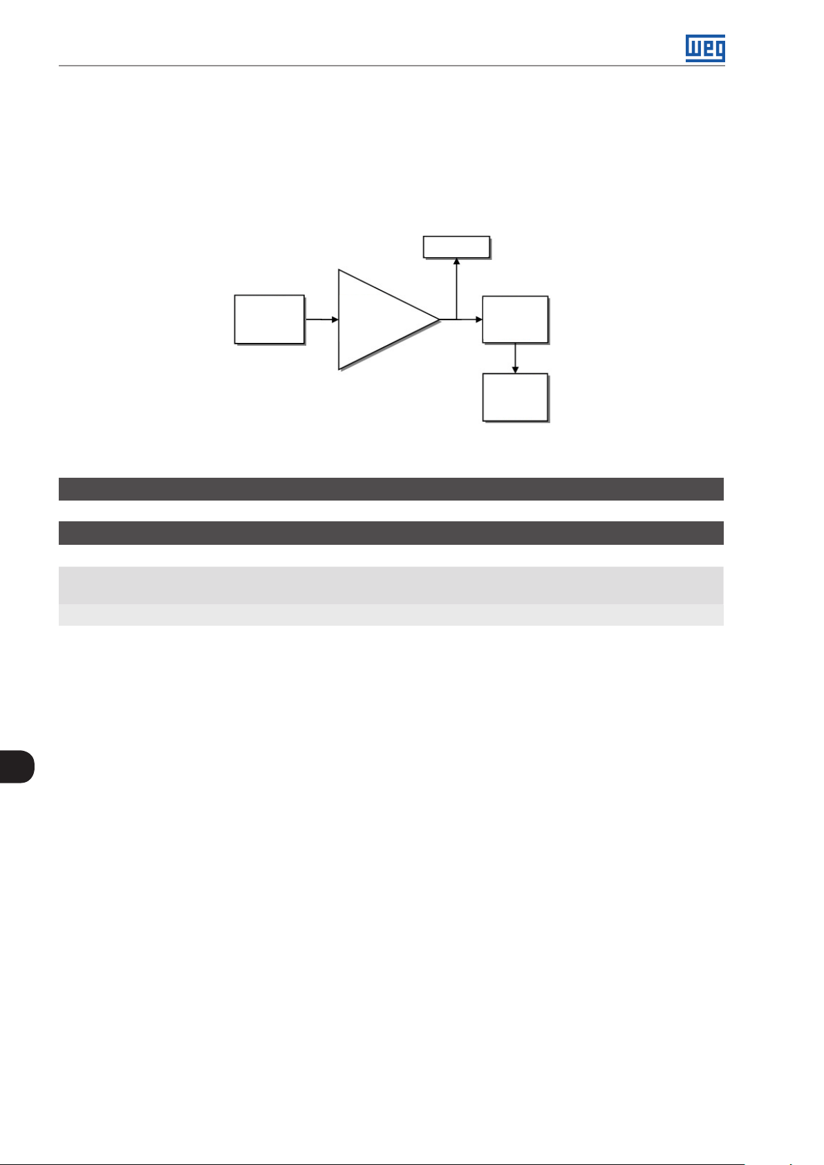
Digital and Analog Inputs and Outputs
12.3 ANALOG OUTPUT
The analog output (AOx) is configured by means of three types of parameters: Function, Gain and Signal, according
to the block diagram below.
The quantity of analog outputs depends on the expansion accessory IO's. For further details, refer to the installation,
configuration and operation guide of the IO's expansion accessory used.
AO1 - P014
AO2 - P015
Function
AO1 - P251
AO2 - P254
(*) Control terminals available on the accessory.
Figure 12.3: Block diagram of the analog output (AOx)
Gain
AO1 - P252
AO2 - P255
Signal
AO1 - P253
AO2 - P256
Value
(*)
AO1
(*)
AO2
P014 - Value of Analog Output AO1
P015 - Value of Analog Output AO2
Adjustable
Range:
Properties:
Description:
These read-only parameters indicates the value of analog outputs AO1 and AO2 in percentage of the full scale.
The indicated values is obtained after multiplication by the gain. Check the description of the parameters P251
to P256.
0.0 to 100.0% Factory
Setting:
ro
12
12-6 | CFW300
Page 99

P251 - AO1 Function
P254 - AO2 Function
Digital and Analog Inputs and Outputs
Adjustable
Range:
Properties:
0 = Speed Ref.
1 = Not Used
2 = Real Speed
3 and 4 = Not Used
5 = Output Current
6 = Not Used
7 = Active Current
8 to 10 = Not Used
11 = Motor Torque
12 = SoftPLC
13 to 15 = Not Used
16 = Motor Ixt
17 = Not Used
18 = Content of P696
19 = Content of P697
20 = Not Used
21 = Application Function 1
22 = Application Function 2
23 = Application Function 3
24 = Application Function 4
25 = Application Function 5
26 = Application Function 6
27 = Application Function 7
28 = Application Function 8
29 = Control Setpoint (PID Controller Application)
30 = Process Variable (PID Controller Application)
Factory
Setting:
P251 = 2
P254 = 5
Description:
These parameters sets the functions of the analog outputs, according to function and scale presented in Tab le
12.3 on page 12-7.
Tabl e 12 . 3 : Full scale of the analog output
Function Description Full Scale
0 Speed reference at the input of the ramp P001 P134
2 Effective speed at the inverter output P134
5 Total output current RMS 2 x P295
7 Active current 2 x P295
11 Torque on the motor in relation to the rated torque 200.0 %
12 SoftPLC scale for analog output 32767
16 Ixt overload of the motor (P037) 100 %
18 Value of P696 for analog output AOx 32767
19 Value of P697 for analog output AOx 32767
29 Control Setpoint (PID Controller Application)
30 Process Variable (PID Controller Application)
(*) For further details refer the Chapter 18 APPLICATIONS on page 18-1.
(*)
(*)
12
CFW300 | 12-7
Page 100

Digital and Analog Inputs and Outputs
P252 - AO1 Gain
P255 - AO2 Gain
Adjustable
Range:
Properties:
Description:
It determines the analog outputs gain according to the equations of Table 12.4 on page 12-8.
0.000 to 9.999 Factory
Setting:
1.000
P253 - AO1 Signal
P256 - AO2 Signal
Adjustable
Range:
Properties:
Description:
These parameters configures if the analog outputs signal will be in current or voltage, with direct or reverse
reference.
0 = 0 to 10 V
1 = 0 to 20 mA
2 = 4 to 20 mA
3 = 10 to 0 V
4 = 20 to 0 mA
5 = 20 to 4 mA
Factory
Setting:
0
12
Table 12.4 on page 12-8 below summarizes the configuration and equation of the analog output, where the
relationship between the analog output function and the full scale is defined by P251 (AO1) or P256 (AO2), as
per Table 12.3 on page 12-7.
Tabl e 12 . 4 : Configuration and equations characteristic of AOx
Signal P253 or P256 Equation
0 to 10 V 0
0 to 20 mA 1
4 to 20 mA 2
10 to 0 V 3
20 to 0 mA 4
20 to 4 mA 5
AOx (%) = x gain x 10 V
AOx (%) = x gain x 20 mA
AOx (%) = x gain x 16 mA + 4 mA
AOx (%) = 10 V - x gain x 10 V
AOx (%) = 20 mA - x gain x 20 mA
AOx (%) = 20 mA - x gain x 16 mA
function
(
scale
function
(
scale
function
(
scale
function
(
scale
function
(
function
(
scale
scale
(
(
(
(
(
(
12-8 | CFW300
 Loading...