

Page 1
Motors | Automation | Energy | Transmission & Distribution | Coatings
Frequency Inverter
Convertidor de Frecuencia
Inversor de Frequência
CFW300
User's Manual
Manual del Usuario
Manual do Usuário
Page 2

User’s Manual
Series: CFW300
Language: English
Document Nº: 10003325037 / 00
Models: Frame Sizes A and B
Publishing Date: 11/2015
Page 3
Summary of Reviews
The information below describes the revisions made to this manual.
English
Version Review Description
-- R00 First edition
ATTENTION!
Check the frequency of the power supply.
In case the power supply frequency is different from the factory setting (check
P403), it is necessary to set:
P204 = 5 for 60 Hz.
P204 = 6 for 50 Hz.
It is only necessary to set these parameters once.
Refer to the programming manual of the CFW300 for further details about the
programming of parameter P204.
Page 4

Contents
1 SAFETY INSTRUCTIONS .................................................................... 1
1.1 SAFETY WARNINGS IN THE MANUAL .................................................... 1
1.2 SAFETY WARNINGS IN THE PRODUCT ................................................. 1
1.3 PRELIMINARY RECOMMENDATIONS ....................................................2
2 GENERAL INFORMATION ..................................................................3
2.1 ABOUT THE MANUAL .............................................................................. 3
2.2 ABOUT THE CFW300 ................................................................................ 3
2.3 TERMINOLOGY .........................................................................................6
2.4 IDENTIFICATION LABEL .........................................................................7
2.5 RECEIVING AND STORAGE .....................................................................8
3 INSTALLATION AND CONNECTION ..................................................9
3.1 MECHANICAL INSTALLATION .................................................................9
3.1.1 Environmental Conditions ..............................................................9
3.1.2 Positioning and Mounting...............................................................9
3.1.2.1 Cabinet Mounting ................................................................9
3.1.2.2 Surface Mounting ............................................................. 10
3.1.2.3 DIN-Rail Mounting .............................................................10
3.2 ELECTRICAL INSTALLATION ................................................................10
3.2.1 Identification of the Power Terminals and Grounding Points .10
3.2.2 Circuit Breakers, Fuses, Grounding and Power ....................... 11
3.2.3 Power Connections .......................................................................12
3.2.3.1 Input Connections .............................................................14
3.2.3.2 Power Supply Reactance ................................................14
3.2.3.3 Dynamic Braking ...............................................................15
3.2.3.4 Output Connections .........................................................16
3.2.4 Grounding Connections ............................................................... 17
3.2.5 Control Connections ....................................................................17
3.2.6 Cable Separation Distance ..........................................................18
3.3 INSTALLATIONS ACCORDING TO EUROPEAN DIRECTIVE OF
ELECTROMAGNETIC COMPATIBILITY .....................................................18
3.3.1 Control Connections .....................................................................19
3.3.2 Emission and Immunity Levels .................................................... 19
3.3.3 Characteristics of the RFI Filter .................................................20
English
4 KEYPAD (HMI) AND BASIC PROGRAMMING ................................21
4.1 USE OF THE KEYPAD TO OPERATE THE INVERTER .........................21
4.2 INDICATIONS ON THE HMI DISPLAY ...................................................21
4.3 OPERATING MODES OF THE HMI ........................................................21
5 FIRST TIME POWER-UP AND START-UP .......................................23
5.1 START-UP PREPARATION ......................................................................23
5.2 START-UP ................................................................................................23
5.2.1 Basic Application...........................................................................24
5.2.2 V/f Type of Control (P202 = 0) ......................................................25
5.2.3 Control Type VV W (P202 = 5).......................................................26
Page 5

Contents
6 TROUBLESHOOTING AND MAINTENANCE ...................................27
English
6.1 FAULTS AND ALARMS ............................................................................27
6.2 SOLUTION FOR THE MOST FREQUENT PROBLEMS ........................27
6.3 INFORMATION NECESSARY FOR CONTACTING TECHNICAL
SUPPORT .......................................................................................................27
6.4 PREVENTIVE MAINTENANCE................................................................28
6.5 CLEANING INSTRUCTIONS ..................................................................29
7 ACCESSORIES ..................................................................................30
8 TECHNICAL SPECIFICATIONS ........................................................31
8.1 POWER DATA ...........................................................................................31
8.2 ELECTRONICS/GENERAL DATA ...........................................................32
8.2.1 Considered Standards ..................................................................33
APPENDIX A - FIGURES .................................................................... 110
APPENDIX B - TECHNICAL SPECIFICATIONS ................................ 113
Page 6
Safety Instructions
1 SAFETY INSTRUCTIONS
This manual provides information for the proper installation and operation of the CFW300
frequency inverter.
It has been written to be used by qualified personnel with suitable training or technical
qualification for operating this type of equipment. The personnel shall follow all the safety
instructions described in this manual and/or defined by the local regulations. Failure to comply
with the safety instructions may result in death, serious injury, and equipment damage.
1.1 SAFETY WARNINGS IN THE MANUAL
The following safety notices are used in the manual:
DANGER!
The procedures recommended in this warning have the purpose of protecting the
user against death, serious injuries and considerable material damage.
ATTENTION!
The procedures recommended in this warning have the purpose of avoiding
material damage.
NOTE!
The information mentioned in this warning is important for the proper
understanding and good operation of the product.
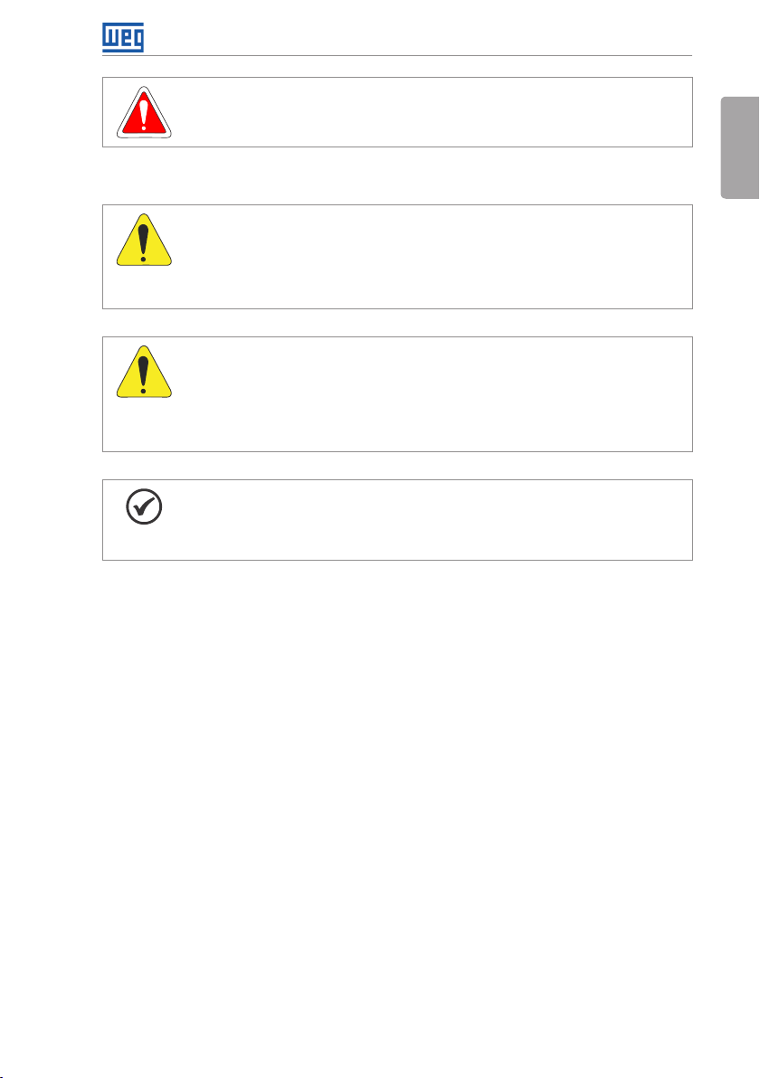
1.2 SAFETY WARNINGS IN THE PRODUCT
The following symbols are attached to the product, serving as safety notices:
English
High voltages are present.
Components sensitive to electrostatic discharge.
Do not touch them.
Mandatory connection to the protective ground (PE).
Connection of the shield to the ground.
CFW300 | 1
Page 7

Safety Instructions
1.3 PRELIMINARY RECOMMENDATIONS
English
DANGER!
Always disconnect the main power supply before touching any electrical
component associated to the inverter. Several components can remain charged
with high voltages or remain in movement (fans) even after the AC power is
disconnected or switched off.
Wait at least ten minutes after turning off the input power for the complete
discharge of the power capacitors.
Always connect the grounding point of the inverter to the protection earth (PE).
DANGER!
The XC10 connector does is not USB compatible, therefore, it cannot be
connected to USB ports.
This connector only serves as the interface between the CFW300 frequency
inverter and its accessories.
NOTES!
Frequency Inverter may interfere with other electronic equipment. In order to
reduce these effects, take the precautions recommended in the Chapter 3
INSTALLATION AND CONNECTION on page 9.
Read the user's manual completely before installing or operating the inverter.
Do not perform any withstand voltage test!
If necessary, contact the manufacturer.
ATTENTION!
Electronic boards have components sensitive to electrostatic discharges.
Do not touch directly on components or connectors.
If necessary, first touch the grounding point of the inverter, which must be
connected to the protection earth (PE) or use a proper grounding strap.
2 | CFW300
Page 8
2 GENERAL INFORMATION
2.1 ABOUT THE MANUAL
General Information
This manual contains information for the proper installation and operation of the inverter,
commissioning, main technical features and how to identify the most usual problems of the
different models of inverters of the CFW300 line.
ATTENTION!
The operation of this equipment requires detailed installation and operation
instructions provided in the quick installation guide, user's manual, programming
manual and communication manuals. The guides are provided in print with their
respective accessory, or can be obtained at WEG website - www.weg.net. A
printed copy of the files can be requested at your local WEG dealer.
NOTE!
It is not the intention of this manual to present all the possibilities for the application
of the CFW300, as well as WEG cannot take any liability for the use of the CFW300
which is not based on this manual.
Part of the figures and tables are available in the annexes, which are divided into APPENDIX
A - FIGURES on page 110 for figures and APPENDIX B - TECHNICAL SPECIFICATIONS on
page 113 for technical specifications.
For further information, refer to the programming manual.
2.2 ABOUT THE CFW300
The CFW300 frequency inverter is a high-performance product which allows speed and torque
control of three-phase induction motors. This product provides the user with the options of
vector (VVW) or scalar (V/f) control, both programmable according to the application.
English
In the vector mode (V VW ), the operation is optimized for the motor in use, obtaining a better
performance in terms of speed regulation.
The scalar mode (V/f) is recommended for simpler applications, such as the activation of most
pumps and fans. In such cases it is possible to reduce the losses in the motor and the inverter
using the "V/f Quadratic", which results in energy savings. The V/f mode is used when more
than a motor is activated by an inverter simultaneously (multimotor applications).
The frequency inverter CFW300 also has functions of PLC (Programmable Logic Controller)
by means of the SoftPLC (integrated) feature. For further details regarding the programming of
those functions, refer to the SoftPLC user's manual of the CFW300.
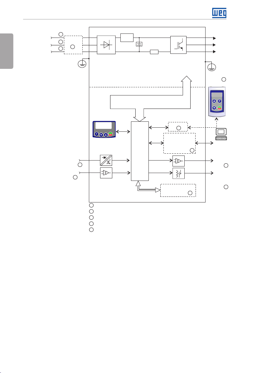
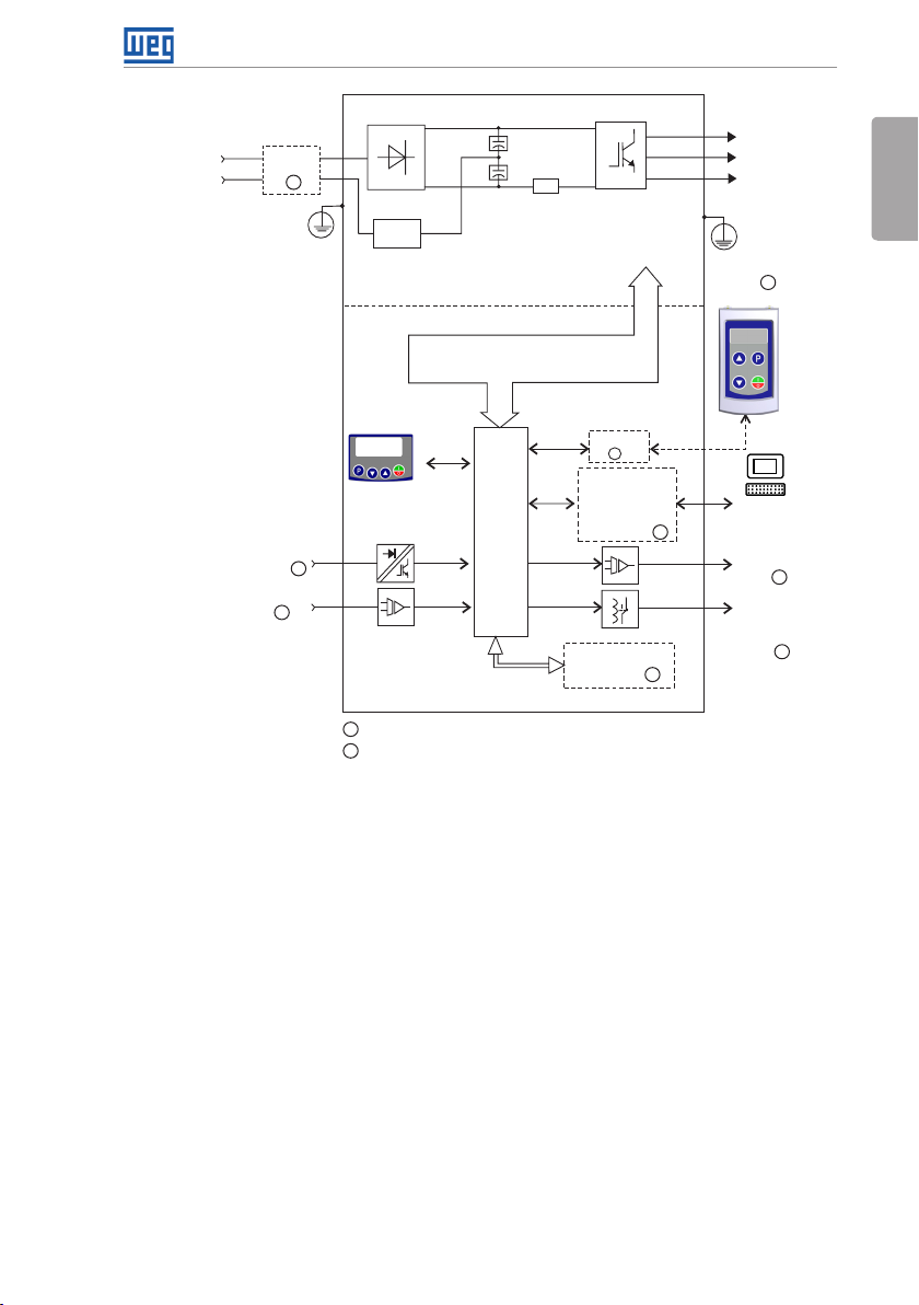
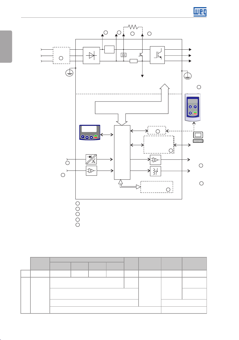
The main components of the CFW300 can be viewed in the blocks diagrams of Figure 2.1 on
page 4, for frame size A 220 V, Figure 2.2 on page 5 for frame size A 110 V and Figure
2.3 on page 6 for frame size B 220 V.
CFW300 | 3
Page 9
General Information
English
supply
S/L2/N (+UD)
R/L1/L (-UD)
Power
T/L 3
1
1
2
Filter RFI
5
PE
Single-phase /
three-phase
rectifier
Power
Preload
DC Link
capacitor
bank
Rsh
Inverter
with IGBT
transistors
U/T1
V/T2
Motor
3~
W/T3
PE
HMI (remote)
3
Control
Digital inputs
(DI1 to DI4)
Analog input
(AI1)
Sources for electronics and interfaces between
HMI
4
4
1
DC power supply connection available for specific models only
2
Three-phase power supply connection available for specific models only
3
Available as accessory
4
Number of Inputs/O utputs depends o n the I/O expansion ac cessory used
5
Available as accessory only in models single-phase
power and control
Control
board
with
CPU
16 bits
RS-485
3
Interfaces (RS-232,
RS-485, USB,
CANopen, Dev iceNet,
Profibus DP or
Bluetooth)
Flash Memory
Module
PC
Software
3
WPS
Analog
output
(AO1)
Digital
output
DO1
(R L1)
4
4
3
Figure 2.1: Block diagram of CFW300 for frame size A 220 V
4 | CFW300
Page 10
Power
supply
L1/L
L2/N
Filter
RFI
1
PE
Single-phase /
three-phase rectifier
Preload
Power
Control
Rsh
DC Link
capacitor
bank
Sources for electronics and interfaces
between power and control
Inverter
with IGBT
transistors
General Information
U/T1
Motor
V/T2
3~
W/T3
PE
1
HMI (remote)
English
Digital inputs
(DI1 to DI4)
Analog input
(AI1)
HMI
2
Control
board
with
CPU
16 bits
Interfaces (RS-232,
CANopen, Dev iceNet,
2
Flash Memory
1
Available as accessory
2
Number of Inputs/O utputs depends o n the I/O expansion ac cessory used
Figure 2.2: Block diagram of CFW300 for frame size A 110 V
RS-485
1
RS-485, USB,
Profibus DP or
Bluetooth)
Module
PC
Software
1
WPS
Analog
output
(AO1)
Digital
output
DO1
(R L1)
2
2
1
CFW300 | 5
Page 11
General Information
English
R/L1/L
Power
supply
S/L2/N
T/L 3
Digital inputs
(DI1 to DI4)
Analog input
Filter RFI
(AI1)
5
Three-phase
rectifier
PE
Power
Control
HMI
3
3
1 1
+UD -UD +BR BR
Preload
Sources for electronics and interfaces between
4 4
Rsh
DC Link
capacitor
bank
power and control
Control
board
with
CPU
16 bits
Inverter
with IGBT
transistors
Braking
IGBT
RS-485
Interfaces (RS-232,
RS-485, USB,
CANopen, Dev iceNet,
Profibus DP or
Bluetooth)
Flash Memory
Module
U/T1
V/T2
Motor
3~
W/T3
PE
2
HMI (remote)
2
2
2
PC
Software
WPS
Analog
output
(AO1)
Digital
output
DO1
(R L1)
3
3
DC power supply connection
1
Available as accessory
2
3
Number of Inputs/O utputs depends o n the I/O expansion ac cessory used
Braking resistor connection
4
Available as accessory only in models single-phase
5
Figure 2.3: Block diagram of CFW300 for frame size B 220 V
2.3 TERMINOLOGY
Tab le 2 .1: Terminology of the CF W300 inverters
Product
and Series
E.g.: CFW300 A 01P6 S 2 NB 20 --- ---
CFW300
Available options
Refer to Table 2.2 on page 7
NB = without braking reostática Sx = special
DB = with braking reostática Blank = standard
20 = IP20 Hx = special hardware
6 | CFW300
Model Identification
Frame
Size
Rated
Current
Phase
Number
Rated
Voltage
Brake
Degree of
Protection
Hardware
Version
Software
Version
Blank =
standard
software
Page 12
General Information
Tab le 2 .2 : Available options for each field of the nomenclature according to the rated current and voltage of the inverter
Frame Size
A
B
Output Rated
Current
01P6 = 1.6 A
02P6 = 2.6 A
04P2 = 4.2 A
06P0 = 6.0 A
01P6 = 1.6 A
02P6 = 2.6 A
04P2 = 4.2 A
06P0 = 6.0 A
07P3 = 7.3 A
01P6 = 1.6 A
02P6 = 2.6 A
04P2 = 4.2 A
06P0 = 6.0 A
07P3 = 7.3 A
01P6 = 1.6 A
02P6 = 2.6 A
04P2 = 4.2 A
06P0 = 6.0 A
07P3 = 7.3 A
10P0 = 10.0 A B = single-phase or three-phase power supply or DC
15P2 = 15.2 A T = three-phase power supply or DC
S = single -phase power supp ly
T = three-phase power supply
D = DC power supply 3 = 280...340 Vdc
N° of Phases
Rated
Volta ge
1 = 110...127 Vac
2 = 200...240 Vac
2 = 200...240 Vac or
280...340 Vdc
Brake
NB
DB
English
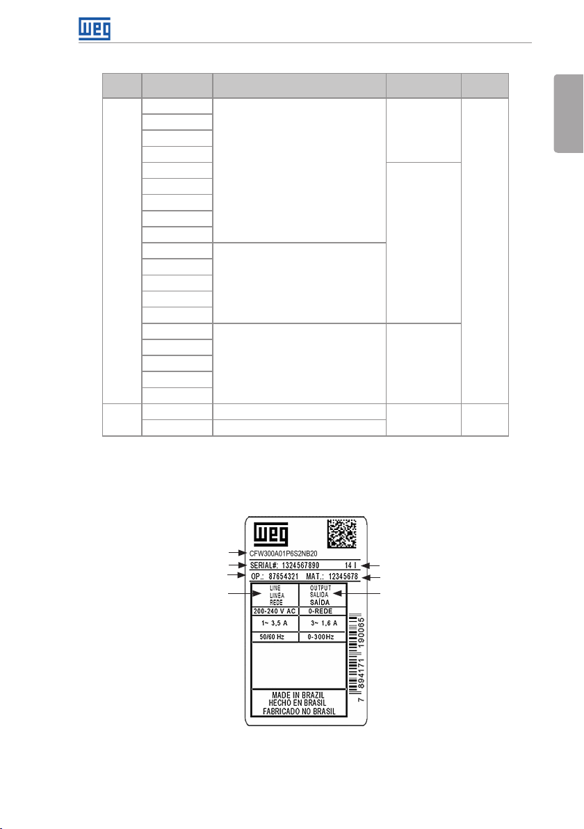
2.4 IDENTIFICATION LABEL
The identification label is located on the side of the inverter. For further details on positioning
the label, refer to Figure A2 on page 110.
Model (Inverter
intelligent code)
Serial number
Production order
Rated input data
(voltage, current and
frequency)
Figure 2.4: Description of the CFW300 identification label
CFW30 0 Side Label
Manufacturing date
(14 corresponds to the
week and I to the year)
WEG stock item
Rated output data
(voltage, current
and frequency)
CFW300 | 7
Page 13
General Information
2.5 RECEIVING AND STORAGE
English
The CFW300 is supplied packed in a cardboard box. There is an identification label affixed to
the outside of the package, identical to the one affixed to the side of the inverter.
Verify whether:
The CFW300 identification label corresponds to the purchased model.
Any damage occurred during transportation.
Report any damage immediately to the carrier.
If the CFW300 is not installed soon, store it in a clean and dry location (temperature between
-25 ºC and 60 ºC (-13 ºF and 140 ºF)), with a cover to prevent dust accumulation inside it.
ATTENTION!
When the inverter is stored for a long period, it becomes necessary to perform
the capacitor reforming. Refer to the procedure recommended in Section 6.4
PREVENTIVE MAINTENANCE on page 28 of this manual.
8 | CFW300
Page 14

3 INSTALLATION AND CONNECTION
3.1 MECHANICAL INSTALLATION
Installation and Connection
3.1.1 Environmental Conditions
Avoid:
Direct exposure to sunlight, rain, high humidity or sea-air.
Inflammable or corrosive gases or liquids.
Excessive vibration.
Dust, metallic particles or oil mist.
Environment conditions permitted for the operation of the inverter:
Temperature surrounding the inverter: 0 ºC to 50 ºC ( 32 ºF to 122 ºF) - IP20.
For temperatures surrounding the inverter higher than the specifications above, it is necessary
to apply a 2 % of current derating for each degree Celsius, limited to an increase of 10 ºC (50 ºF).
Air relative humidity: 5 % to 95 % non-condensing.
Maximum altitude: up to 1000 m (3.300 ft) - rated conditions.
From 1000 m to 4000 m (3.300 ft to 13.200 ft) - 1 % of current derating for each 100 m
above 1000 m of altitude.
Pollution degree: 2 (according to EN50178 and UL508C), with non-conductive pollution.
Condensation must not originate conduction through the accumulated residues.
3.1. 2 Positioning and Mounting
English
The external dimensions and fixing holes, and the inverter net weight (mass) are shown in
Figure B1 on page 116.
Mount the inverter in the upright position on a flat and vertical surface. Allow the minimum
clearances indicated in Figure B2 on page 117, in order to allow the circulation of the cooling
air. Do not install heat sensitive components right above the inverter.
ATTENTION!
When installing two or more inverters vertically, respect the minimum clearance
A + B (as shown in Figure B2 on page 117) and provide an air deflecting plate
so that the heat rising up from the lower inverter does not affect the top inverter.
Provide independent conduits for the physical separation of signal, control and
power cables (refer to Section 3.2 ELECTRICAL INSTALLATION on page 10).
3.1. 2.1 Cabinet Mounting
For inverters installed inside cabinets or metallic boxes, provide proper exhaustion, so that the
temperature remains within the allowed range. Refe r to the dissipated powers i n Table B2 on page 114.
CFW300 | 9
Page 15
Installation and Connection
As a reference, Table 3.1 on page 10 shows the air flow of rated ventilation for each model.
English
Cooling Method: internal fan with air flow upwards.
Tab le 3 .1: Air flow of the internal fan
Model CFM I/s m3/min
A
B
17. 0 8.02 0.48
3.1.2.2 Surface Mounting
Figure B2 on page 117 illustrates the CFW300 installation procedure for surface mounting.
3.1. 2.3 DIN-Rail Mounting
The CFW300 inverter can also be mounted directly on a 35 mm-rail, in accordance with
DIN EM 50.022. For further details, refer to Figure B2 on page 117.
3.2 ELECTRICAL INSTALLATION
DANGER!
The following information is merely a guide for proper installation. Comply with
applicable local regulations for electrical installations.
Make sure the AC power supply is disconnected before starting the installation.
The CFW300 must not be used as an emergency stop device. Provide other
devices for that purpose.
3.2 .1 Identification of the Power Terminals and Grounding Points
The power terminals can be of different sizes and configurations, depending on the model of
the inverter, according to Figure B3 on page 118. The location of the power, grounding and
control connections are shown in Figure B3 on page 118.
Description of the power terminals:
L/L1, N/L2, L3 (R,S,T): power supply connection.
U, V and W: connection for the motor.
-UD: negative pole of the DC power supply.
+UD: positive pole of the DC power supply.
+BR, BR: connection of the braking resistor (available for frame size B models).
PE: grounding connection.
The maximum tightening torque of the power terminals and grounding points must be checked
in Figure B3 on page 118.
10 | CFW300
Page 16
Installation and Connection
DANGER!
Observe the correct DC power supply connection, polarity and terminal positions.
3.2.2 Circuit Breakers, Fuses, Grounding and Power
ATTENTION!
Use proper cable lugs for the power and grounding connection cables. Refer
to Table B1 on page 113 for recommended wiring, circuit breakers and fuses.
Keep sensitive equipment and wiring at a minimum distance of 0.25 m (9.85 in)
from the inverter and from the cables connecting the inverter to the motor.
ATTENTION!
Residual differential interrupter (DR):
When used in the inverter supply, it must have a pick-up current of 300 mA.
Depending on the installation conditions, such as motor cable length and type,
multi-motor drive, etc., the DR interrupter may trip. Check with the manufacturer
the most suitable type for operation with inverters.
NOTE!
The wire gauges listed in Table B1 on page 113 are guiding values. Installation
conditions and the maximum permitted voltage drop must be considered for
the proper wiring sizing.
English
CFW300 | 11
Page 17
Installation and Connection
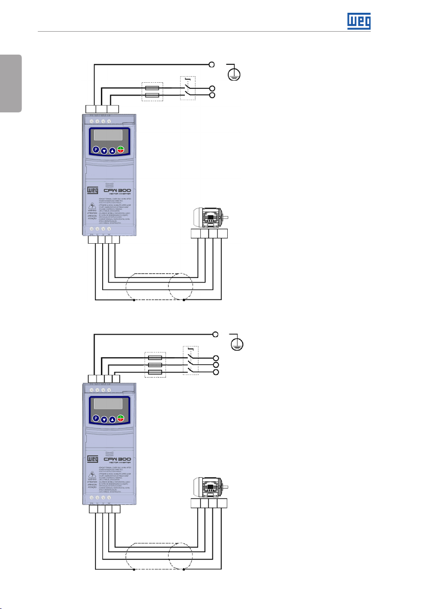
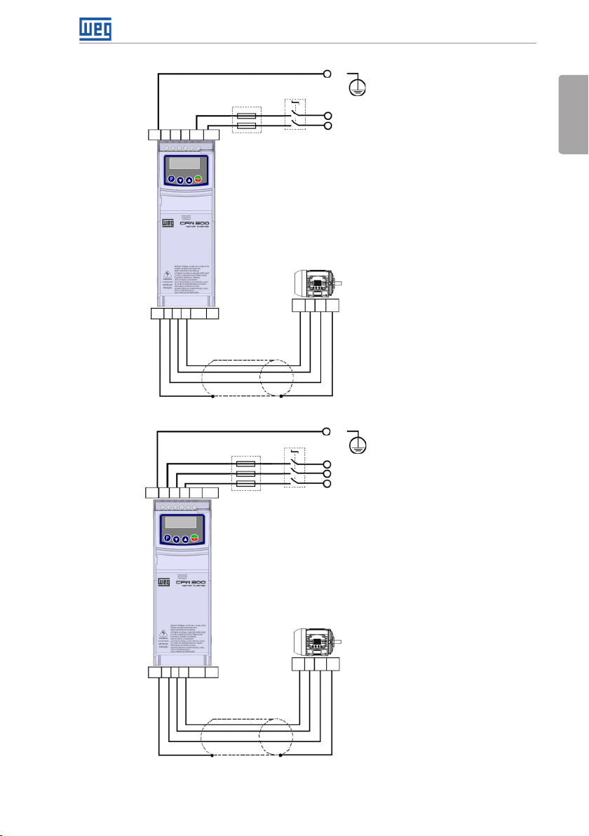
3.2.3 Power Connections
English
PE
Power
supply
Negative pole of the DC power supply (-UD)
Disconnecting
PE
+UD-UD
Fuses
switch
Positive pole of the DC power supply (+UD)
UPE
V W
Shielding
Only available for the specific models of frame A (see Table 2.2 on page 7).
(a) Frame size A DC power supply
PE L1 L2L3
U V WPE
Fuses
Disconnecting
switch
PEW V U
Power
supply
PEW V U
PE
L1/L
L2/N
L3
*
12 | CFW300
Shielding
(*) The power ter minal L3 is not available in mo dels of frame size A si ngle-phase
(b) Frame size A single-phase and three-phase power supply
Page 18
PE L2L1
Installation and Connection
PE
Power
supply
Negative pole of the DC power supply (-UD)
+UD-UD
L3
Fuses
Disconnecting
switch
Positive pole of the DC power supply (+UD)
English
U V WPE +BR BR
PE L2L1
U V WPE BR+BR
L3-UD
Shielding
(c) Frame size B DC power supply
Fuses
Disconnecting
switch
+UD
PEW V U
Power
supply
PEW V U
PE
L1/L
L2/N
L3
Shielding
Only available for the 10-A model (see Table 2.2 on page 7).
(d) Frame size B single-phase and three-phase power supply
Figure 3.1: (a) to (d) Power and grounding connections
CFW300 | 13
Page 19
Installation and Connection
3.2.3.1 Input Connections
English
DANGER!
Provide a disconnect device for the inverter power supply. This device must cut
off the power supply whenever necessary (during maintenance for instance).
ATTENTION!
The power supply that feeds the inverter must have a grounded neutral.
NOTE!
The input power supply voltage must be compatible with the inverter rated
voltage.
Power factor correction capacitors are not needed at the input (L/L1, N/L2,
L3) and must not be installed at the output (U, V, W).
Power supply capacity
Suitable for use in circuits capable of delivering not more than 30.000 A
/ 240 V).
In case the CFW300 is installed in power supplies with current capacity over 30.000 A
symmetrical at (127
rms
it is necessary to use proper protection circuits for those power supplies, such as fuses or
circuit breakers.
3.2.3.2 Power Supply Reactance
In a general way, the inverters of the CFW300 line can be installed directly in the power supply,
without reactance in the supply. However, check the following:
,
rms
In order to prevent damages to the inverter and assure the expected useful life, you must
have a minimum impedance that provides a line voltage drop of 1 %. If the line impedance
(due to the transformers and cabling) is below the values listed in this table, we recommend
the use of a line reactance.
For the calculation of the line reactance necessary to obtain the desired percentage voltage
drop, use:
V
L = 1592 . ΔV .
I
s, rat
. f
e
[ μH]
Seeing that:
ΔV - desired line drop, in percentage (%).
V
- phase voltage in the inverter input, in volts (V).
e
I
- rated current of the inverter output.
s, rat
f - line frequency.
14 | CFW300
Page 20
Installation and Connection
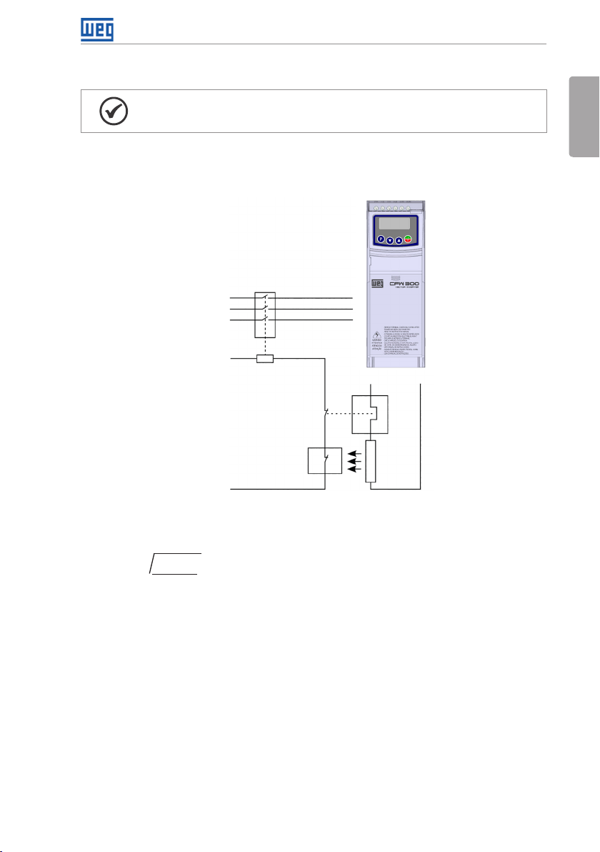
3.2.3.3 Dynamic Braking
NOTE!
The dynamic braking is available from frame size B.
Refer to Table B1 on page 113 for the following specifications of the dynamic braking: maximum
current, resistance, effective current (*) and cable gauge.
English
Input power
supply
power supply
Contactor
Command
Figure 3.2: Installation of brake resistor
Relay
Thermostat
R
S
T
BR+BR
Brake
resistor
(*) The effective braking current can be calculated as follows:
= I
max
tbr
.
5
I
effective
√
(min)
Seeing that: tbr corresponds to the sum of the braking actuation times during the most severe
cycle of five minutes.
The power of the brake resistor must be calculated considering the deceleration time, the inertia
of the load and of the resistive torque.
Procedure to use the dynamic braking:
Connect the brake resistor between the power terminals +BR and BR.
Use a twisted cable for the connection. Separate these cables from the signal and control
wiring.
Dimension the cables according to the application, observing the maximum and effective
currents.
CFW300 | 15
Page 21
Installation and Connection
If the brake resistor is mounted within the cabinet of the inverter, consider its energy when
dimensioning the ventilation of the cabinet.
English
DANGER!
The internal braking circuit and the resistor may be damaged if the latter is not
properly dimensioned and/or if the voltage of the input power supply exceeds the
maximum value permitted. In order to avoid the destruction of the resistor or risk
of fire, the only guaranteed method is the inclusion of a thermal relay in series with
the resistor and/or a thermostat in contact with its housing, connected in such
a way to disconnect the input power supply of the inverter in case of overload,
as shown in Figure 3.2 on page 15.
Set P151 at maximum value when using dynamic braking.
The voltage level on the DC Link for activation of the dynamic braking is defined by the
parameter P153 (level of the dynamic braking).
Refer to the CFW300 programming manual.
3.2.3.4 Output Connections
ATTENTION!
The inverter has an electronic motor overload protection that must be adjusted
according to the driven motor. When several motors are connected to the same
inverter, install individual overload relays for each motor.
The motor overload protection available in the CFW300 is in accordance with
the UL508C standard. Note the following information:
1. Trip current equal to 1.2 times the motor rated current (P401).
ATTENTION!
If a disconnect switch or a contactor is installed at the power supply between the
inverter and the motor, never operate it with the motor spinning or with voltage
at the inverter output.
The characteristics of the cable used to connect the motor to the inverter, as well as its
interconnection and routing, are extremely important to avoid electromagnetic interference in
other equipment and not to affect the life cycle of windings and bearings of the controlled motors.
Keep motor cables away from other cables (signal cables, sensor cables, control cables, etc.),
according to Item 3.2.6 Cable Separation Distance on page 18.
When using shielded cables to install the motor:
Follow the recommendations of IEC60034-25.
Use the low impedance connection for high frequencies to connect the cable shield to the
grounding.
16 | CFW300
Page 22
Installation and Connection
3.2.4 Grounding Connections
DANGER!
The inverter must be connected to a protective ground (PE).
Use a minimum wire gauge for ground connection equal to the indicated in
Table B1 on page 113.
Connect the inverter grounding connections to a ground bus bar, to a single
ground point or to a common grounding point (impedance ≤ 10 Ω).
The neuter conductor of the line that feeds the inverter must be solidly
grounded; however, this conductor must not be used to ground the inverter.
Do not share the grounding wiring with other equipment that operate with high
currents (e.g.: high voltage motors, welding machines, etc.).
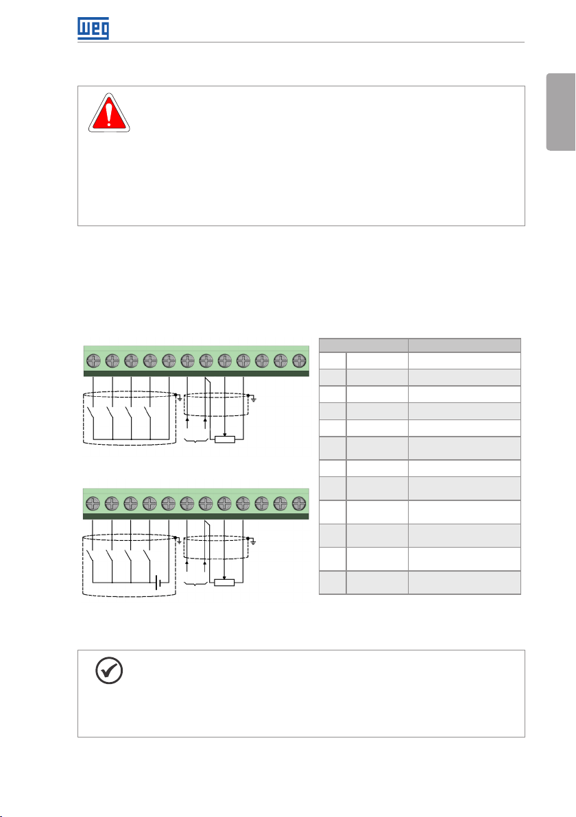
3.2.5 Control Connections
The control connections must be made in accordance with the specification of the connector
of the CFW300 control board. Functions and typical connections are presented in Figure 3.3 on
page 17. For further details on the specifications of the connector signals, refer to Chapter
8 TECHNICAL SPECIFICATIONS on page 31.
1
223344556677889
DI1DI1
1
(External supply)
DI4DI4
DI2DI2
DI3DI3
(a) NPN Configuration
24 V
(b) PNP Configuration
GNDGND
(+) A I1 (-)
(0 a 20) mA
(4 a 20) mA
(+) A I1 (-)
(0 a 20) mA
(4 a 20) mA
Figure 3.3: (a) and (b) Signals of C300 control card connector
GNDGND
Counter
clockwise
AI1
(0 a 10) V
Counter
clockwise
AI1
(0 a 10) V
1010111112
+10 V+10 V
Clockwise Clockwise
9
Connector Description
1 DI1 Digital input 1
2 DI2 Digital input 2
3 DI3 Digital input 3
DO1-RL-CDO1-RL-C
DO1-RL-NCDO1-RL-NC
4 DI4 Digital input 4
DO1-RL-NODO1-RL-NO
5 GND Reference 0 V
6 AI1 Analog input 1
7 GND Reference 0 V
8 AI1 Analog input 1
12
9 +10 V Reference +10 Vdc
10 DO1-RL-NC Digital output 1
11 DO1-RL-C Digital output 1
12 DO1-RL-NO Digital output 1
(*) For further information, refer to the detailed specification in
Section 8.2 ELECTRO NICS/GENERAL DATA on page 32.
(Current)
(Tension)
for potentiometer
(NC contact of relay 1)
(Common point of relay 1)
(NO contact of relay 1)
(*)
English
NOTE!
The CFW300 inverters are supplied with the digital inputs configures as active
low (NPN). In order to change the configuration, check the use of parameter
P271 in the programming manual of the CFW300.
Analog input AI1 is set for input 0 to 10 V, in order to change, check parameter
P233 of the programming manual.
CFW300 | 17
Page 23
Installation and Connection
For the correct connection of the control, use:
English
1. Gauge of the cables: 0.5 mm² (20 AWG) to 1.5 mm² (14 AWG).
2. Maximum torque: 0.5 N.m (4.50 lbf.in).
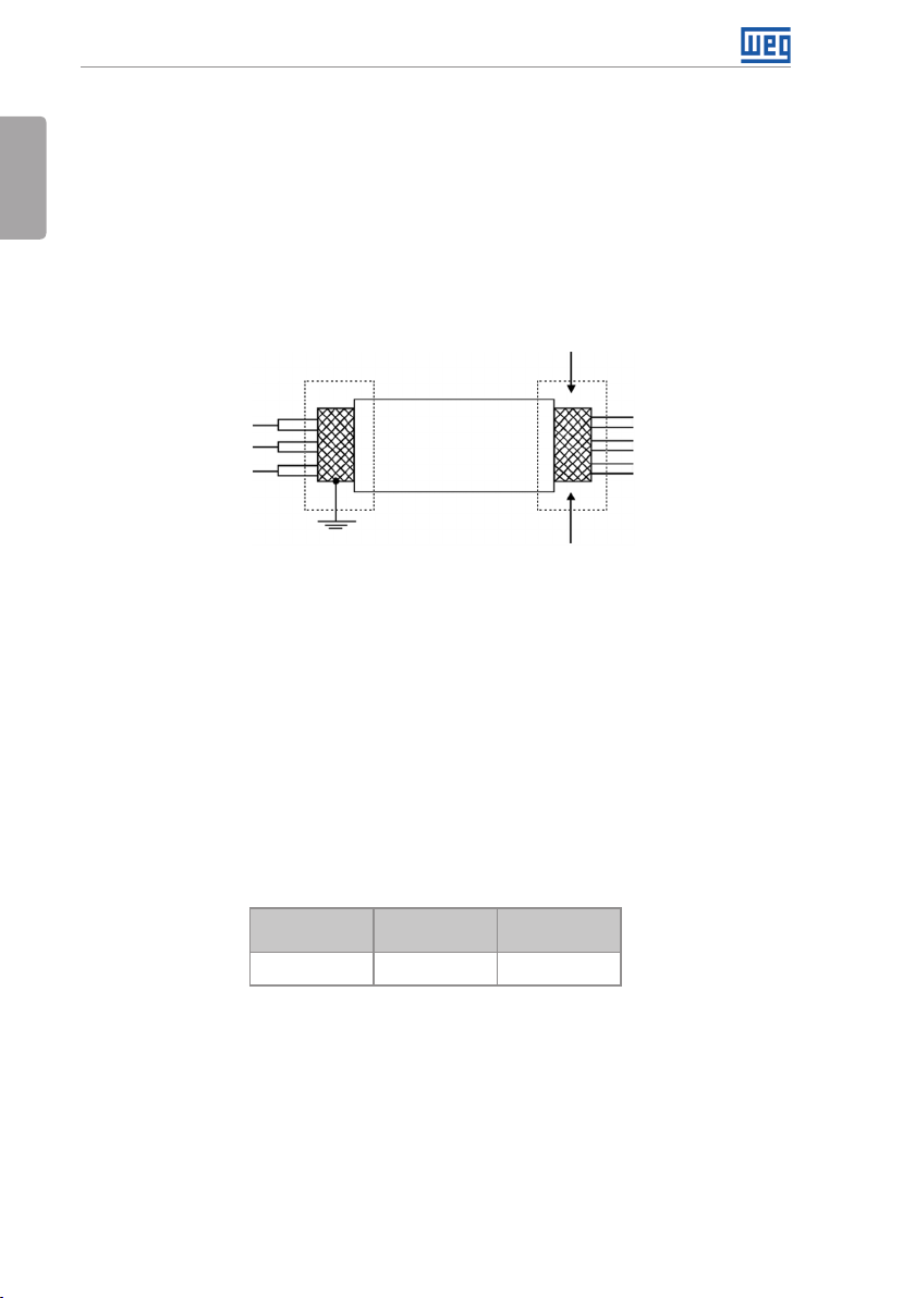
3. Wiring of the connector of the control board with shielded cable and separated from the
other wiring (power, command in 110 V / 220 Vac, etc.), according to Item 3.2.6 Cable
Separation Distance on page 18. If those cables must cross other cables, it must be done
in perpendicularly among them, keeping the minimum separation distance of 5 cm at the
crossing point. Connect the shield according to the figure below:
Insulate with tape
Inverter
side
Do not ground
Figure 3.4: Shield connection
4. Relays, contactors, solenoids or coils of electromechanical brake installed close to the
inverters may occasionally generate interference in the control circuitry. To eliminate this
effect, RC suppressors (with AC power supply) or freewheel diodes (with DC power supply)
must be connected in parallel to the coils of these devices.
5. When using the external HMI (refer to Chapter 7 ACCESSORIES on page 30), the cable
that connects to the inverter must be separated from the other cables in the installation,
keeping a minimum distance of 10 cm (3.95 in).
3.2.6 Cable Separation Distance
Provide separation between the control and the power cables according to Table 3.2 on page 18.
Tab le 3 .2 : Separation distance between cables
Output Rated
Current of t he
Inverter
≤ 24 A
Cable Length
≤ 100 m (330 ft)
> 100 m (330 ft)
Minimum
Separation
Distance
≥ 10 cm (3.95 in)
≥ 25 cm (9.85 in)
3.3 INSTALLATIONS ACCORDING TO EUROPEAN DIRECTIVE OF
ELECTROMAGNETIC COMPATIBILITY
The CFW300 inverters feature external RFI filter to reduce electromagnetic interference (refer
to Chapter 7 ACCESSORIES on page 30). Those inverters, when properly installed, meet
the requirements of the directive of electromagnetic compatibility.
These inverters were developed for professional applications only. Therefore, the limits for
emission of harmonic currents established by the EN 61000-3-2 and EN 61000-3-2/A 14
standards are not applicable.
18 | CFW300
Page 24

Installation and Connection
3.3.1 Control Connections
1. Shielded output cables (motor cables) with the shield connected at both ends, motor and
inverter, with low-impedance connection for high frequency.
Maximum motor cable length and conducted and radiated emission levels according to Table
B3 on page 115.
2. Shielded control cables, and keep them away from other cables according to table 3.2 of
the user's manual.
3. Grounding of the inverter according to instructions of item Item 3.2.4 Grounding Connections
on page 17.
4. Grounded power supply.
5. Use short wiring to ground the external filter or inverter.
6. Ground the mounting plate using a flexible braid as short as possible. Flat conductors have
lower impedance at high frequencies.
7. Use sleeves for cable conduits whenever possible.
3.3.2 Emission and Immunity Levels
EMC Phenomenon
Emission:
Mains Terminal Disturbance Voltage
Frequency Range: 150 kHz to 30 MHz
Electromagnetic Radiation Disturbance
Frequency Range: 30 MHz to 1000 MHz
Immunity:
Electrostatic Discharge (ESD) IEC 61000-4-2 4 kV for contact discharge and 8 kV for air discharge
Fast Transient-Burst IEC 61000-4-4 2 kV / 5 kHz (coupling capacitor) input cables
Conducted Radio-Frequency
Common Mode
Surges IEC 61000-4-5 1.2/50 μs, 8/20 μs
Radio-Frequency Electromagnetic
Field
Tab le 3 .3 : Emission and immunity levels
Basic
Standard
IEC/EN 61800-3 It depends on the inverter model on the length of the
IEC 61000-4-6 0.15 to 80 MHz; 10 V; 80 % AM (1 kHz)
IEC 61000-4-3 80 to 1000 MHz
motor cable. Refer to Table B3 on page 115
1 kV / 5 kHz control cables and remote HMI cables
2 kV / 5 kHz (coupling capacitor) motor cables
Motor, control and remote HMI cables
1 kV line-to-line coupling
2 kV line-to-ground coupling
10 V/m
80 % AM (1 kHz)
Level
English
Definition of Standard IEC/EM 61800-3: "Adjustable Speed Electrical Power Drives
Systems"
Environments:
First Environment: environments that include domestic installations, as well as establishments
directly connected without intermediate transformer to a low-voltage power supply network
which supplies buildings used for domestic purposes.
CFW300 | 19
Page 25
Installation and Connection
Second Environment: aincludes all establishments other than those directly connected to a
English
low-voltage power supply network that supplies buildings used for domestic purposes.
Categories:
Category C1: inverters with a voltage rating less than 1000 V and intended for use in the First
Environment.
Category C2: inverters with a voltage rating less than 1000 V intended for use in the First
Environment, not provided with a plug connector or movable installations. They must be installed
and commissioned by a professional.
Category C3: inverters with a voltage rating less than 1000 V and intended for use in the
Second Environment only (not designed for use in the First Environment).
NOTE!
A professional is a person or organization familiar with the installation and/or
commissioning of inverters, including their EMC aspects.
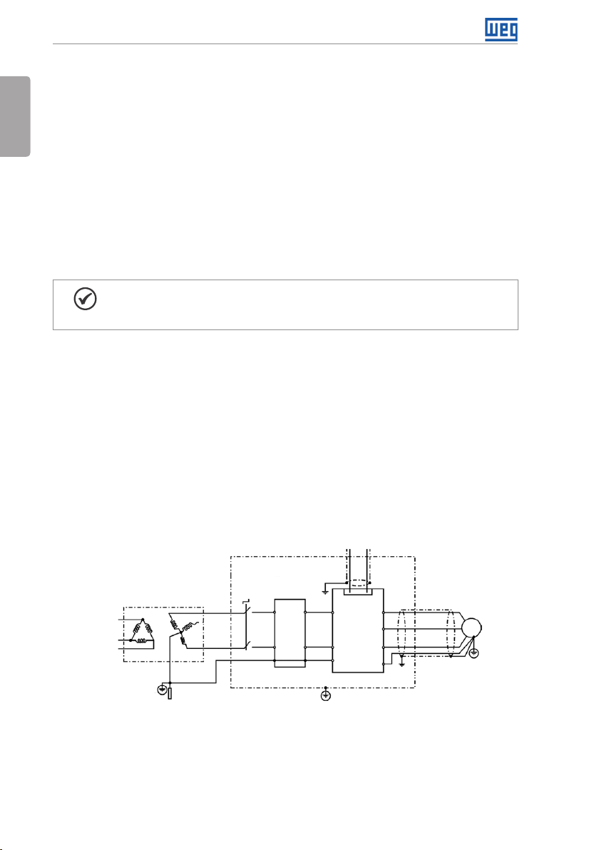
3.3.3 Characteristics of the RFI Filter
CFW300 inverters are installed with external filter when it is intended to reduce the disturbance
conducted from the inverter to the power line in the high frequency band (>150). It is observe
the maximum levels of conducted emission of electromagnetic compatibility standards, such
as EN 61800-3 and EN 55011.
For further details, refer to Section 3.3 INSTALLATIONS ACCORDING TO EUROPEAN DIRECTIVE
OF ELECTROMAGNETIC COMPATIBILITY on page 18.
For further information about the RFI filter model, refer to Table 7.1 on page 30.
The figure below demonstrate the connection of the filter to the inverter:
Signal and control wiring
External input
RFI filter
L1/L L1
L2/N L2
PE PE
Metal panel (when necessary)
1...12
XC1
L1/L
CFW300
L2/N
PE
Protective ground
U
V
W
PE
Motor
Power
supply
Transformer
Grounding
PE
rod
Figure 3.5: Connection of the RFI filter - general conditions
20 | CFW300
Page 26

Keypad (HMI) and Basic Programming
4 KEYPAD (HMI) AND BASIC PROGRAMMING
4.1 USE OF THE KEYPAD TO OPERATE THE INVERTER
Through the HMI, it is possible to command the inverter, visualize and adjust all of its parameters.
The Keypad features the following functions:
Enables/disables the inverter via
Selects (toggles) display
between the parameter
number and its value
(position/content).
Decreases the frequency,
parameter number or
parameter value.
Figure 4.1: HMI keys
Increases the frequency,
parameter number and
parameter value.
acceleration/deceleration ramp
(start/stop, according to P229).
Resets the inver ter after a fault
event.
4.2 INDICATIONS ON THE HMI DISPLAY
Inverter status
Direction of
rotation
Unit of measurement
(it refers to the value
of the main display)
English
Main display
Figure 4.2: Display areas
Bar graph to
monitor the
variable
4.3 OPERATING MODES OF THE HMI
When energizing the inverter, the initial state of the keypad remains in the start-up mode as
long as there is no fault, alarm, undervoltage or any key is pressed.
The setting mode is composed of two levels: level 1 allows the navigation through the
parameters. And level 2 allows the edition of the parameter selected at level 1. At the end of
this level the modified value is saved when the key is pressed.
Figure 4.3 on page 22 illustrates the basic navigation of the operating modes of the HMI.
CFW300 | 21
Page 27
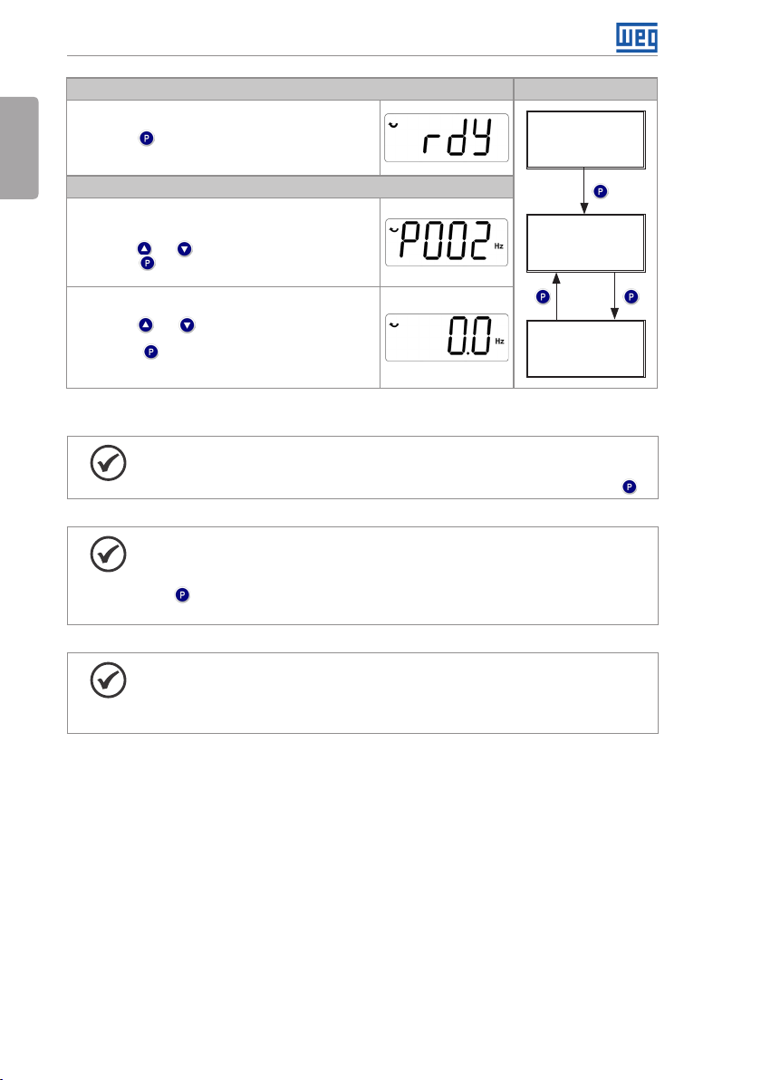
Keypad (HMI) and Basic Programming
English
It is the initial state of the HMI after its successful power-up
(without the occurrence of faults, alarms or undervoltage)
Press key to go to level 1 of the setting mode - selection
of parameters. Pressing any other key also switches to
setting mode
Level 1:
This is the first level of the setting mode. The parameter
number is shown on the main display
Use keys and to find the desired parameter
Press key to go to level 2 of the setting mode - change
of the parameter values
Level 2:
The parameter value is shown on the main display
Use keys and to set the new value in the selected
parameter
Press key to confirm the modification (save the new
value). After confirming the modification, the HMI returns to
level 1 of the setting mode
NOTE!
When the inverter is in the fault state, the main display indicates the number
of the fault in the format Fxxx. Navigation is allowed after activation of key .
NOTE!
When the inverter is in the alarm state, the main display indicates the number
of the alarm in the format Axxx. The navigation is allowed after the activation of
key ; thus, the indication "A" goes to the unit of measurement display until the
situation causing the alarm is solved.
Monitoring Mode
Setting Mode
Figure 4.3: HMI operating modes
Monitoring
Setting
level 1
Setting
level 2
22 | CFW300
NOTE!
A list of parameters is presented in the quick reference of the parameters. For
further information about each parameter, refer to the CFW300 programming
manual.
Page 28

5 FIRST TIME POWER-UP AND START-UP
5.1 START-UP PREPARATION
First Time Power-Up and Start-Up
The inverter must have already been installed according to Chapter 3 INSTALLATION AND
CONNECTION on page 9.
DANGER!
Always disconnect the main power supply before making any connection.
1. Check if the power, grounding and control connections are correct and firm.
2. Remove all the materials left behind from the installation work from inside the inverter or the
cabinet.
3. Verify the motor connections and if its voltage and current are within the inverter rated value.
4. Mechanically uncouple the motor from the load. If the motor cannot be uncoupled, make
sure that any speed direction (forward or reverse) will not result in personnel injury and/or
equipment damage.
5. Close the inverter or cabinet covers.
6. Measure the power supply and verify if it is within the allowed range, according to Chapter
8 TECHNICAL SPECIFICATIONS on page 31.
7. Apply power to the input: close the input disconnecting switch.
8. Check the result of the first time power-up:
The HMI display indicates:
English
Figure 5.1: HMI display when powering up
5.2 START-UP
This section describes the power-up of the inverter with HMI operation, using the minimum
connections of Figure 3.1 on page 13 and without connections in the control terminals.
Furthermore, two types of control will be considered: V/f control (scalar) and vector control
VV W. For further details on the utilization of these types of control refer to the CFW300
programming manual.
CFW300 | 23
Page 29
First Time Power-Up and Start-Up
DANGER!
English
High voltages can be present, even after the disconnection of the power supply.
Wait at least 10 minutes for full discharge.
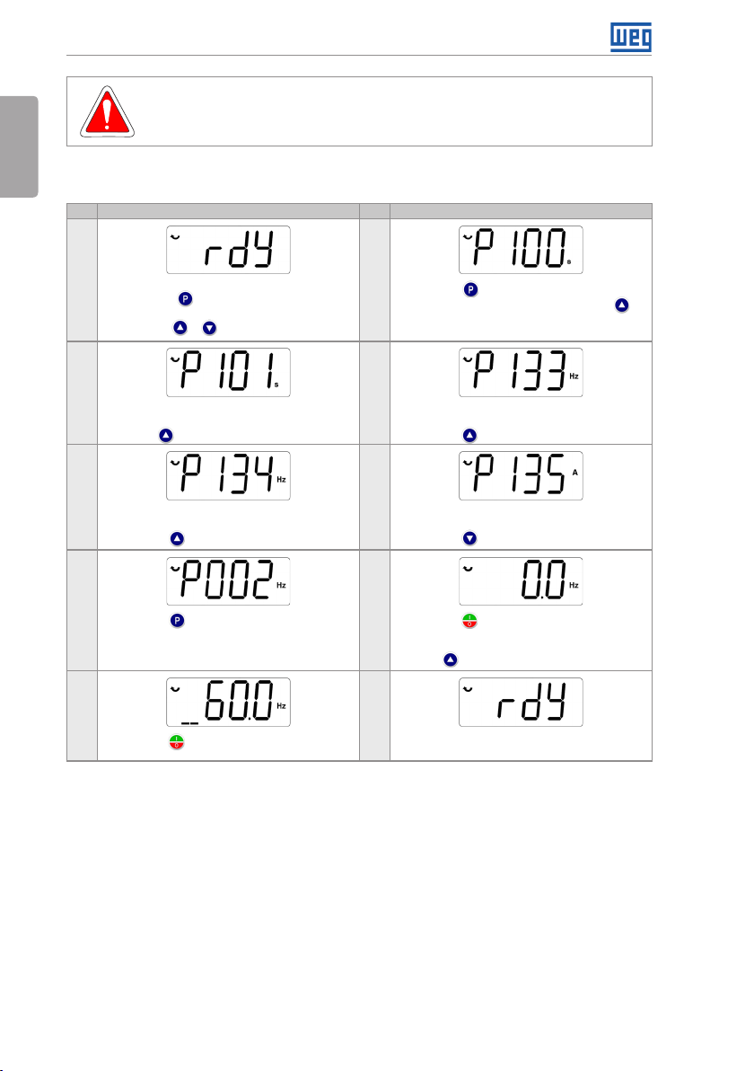
5.2.1 Basic Application
Seq Display Indication/Action Seq Display Indication/Action
Initialization mode
1
Press key to enter the first level of the
parameterization mode
Press keys o r to select th e parameter P100
3 4
If necessary, change the content of "P101 -
Deceleration Time"
Use key to select the parameter P133
5 6
If necessary, change the content of "P134 -
Maximum Speed"
Press key for the next parameter
7 8
Press key to view the parameter content
9 10
Press key . The motor will dece lerate to a stop
Figure 5.2: Sequence for basic application
2
Press key if you need to change the content
of P100 - "Acceleration Time" or press key for
the next parameter
If necessary, change the content of "P133 -
Minimum Speed"
Press key for the next parameter
If necessa ry, change the c ontent of "P135 - Outpu t
Maximum Current"
Press key to select parameter P002
Press key that the motor will accelerate up to
3.0 Hz (factory default set ting of P133 - Minimum
Frequency)
Press and hold it until it reaches 60.0 Hz
When the motor stops, the display will indicate
"ready"
24 | CFW300
Page 30
First Time Power-Up and Start-Up
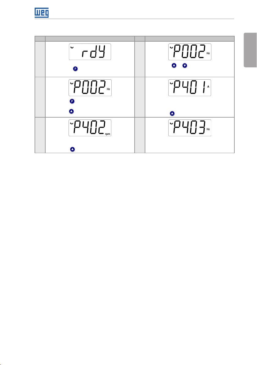
5.2.2 V/f Type of Control (P202 = 0)
Seq Display Indication/Action Seq Display Indication/Action
1
Initialization mode
Press key to enter the first level of the
parameterization mode
3
Press key i f you need to chan ge the content of
"P202 - Type of Control" for P202 = 0 (V/f)
Press key to select parameter P401
5
If necessa ry, change the c ontent of "P402 - Motor
Rated Speed"
Press key for the next parameter
Figure 5.3: Sequence for V/f control
2
Press keys or to select parameter P202
4
If necessary, change the content of parameter
"P401 - Motor Rated Current" according to the
nameplate
Press key for the next parameter
6
If necessa ry, change the c ontent of "P403 - Motor
Rated Frequency"
English
CFW300 | 25
Page 31

First Time Power-Up and Start-Up
5.2.3 Control Type VV W (P202 = 5)
English
Seq Display Indication/Action Seq Display Indication/Action
1
Initialization mode
Press key to enter the first level of the
parameterization mode
3 4
Press key to change the content of "P202 -
Type of Contro l" for P202 = 5 (V VW ). Use key
5 6
If necessa ry, change the c ontent of "P399 - M otor
Rated Efficiency" according to the nameplate
Press key for the next parameter
7 8
If necessa ry, change the c ontent of "P401 - Motor
Rated Current"
Press key for the next parameter
9 10
If necessa ry, change the c ontent of "P403 - Motor
Rated Frequency"
Press key for the next parameter
11 12
If necessa ry, change the co ntent of "P407 - Motor
Rated Power factor"
Press key for the next parameter
2
Press keys or to select parameter P202
Press key to save the change of P202
Use key to select parameter P399
If necessa ry, change the co ntent of "P400 - Motor
Rated Voltage"
Press key for the next parameter
If necessa ry, change the c ontent of "P402 - Motor
Rated Speed"
Press key for the next parameter
If necessa ry, change the c ontent of "P404 - Motor
Rated Power"
Press key for the next parameter
If necessary to make the self-tuning, change the
value of P408 to "I"
13 14
During the self-tuning, the HMI will show "Auto",
and the bar will indicate the operation progress
15
If necessa ry, change the c ontent of "P409 - Sta tor
Resistance"
Figure 5.4: Sequence for VV W control
26 | CFW300
When the self-tuning is completed, it wi ll return to
the (comp) Initialization Mode
Page 32

Troubleshooting and Maintenance
6 TROUBLESHOOTING AND MAINTENANCE
6.1 FAULTS AND ALARMS
NOTE!
Refer to the CFW300 quick reference and the programming manual for further
information on each fault or alarm.
6.2 SOLUTION FOR THE MOST FREQUENT PROBLEMS
Tab le 6 .1: Solution for the most frequent problems
Problem Point to be Verified Corrective Action
Motor will not
start
Motor speed
oscillates
Too high or
too low motor
speed
Display is off HMI connections 1. Check the connections of the inverter external HMI
Incorrect wiring 1. Check all power and control connections.
Analog reference
(if used)
Incorrect settings 1. Check if the parameter values are correct for the application
Fault 1. Check whether the inverter is disabled due to a fault condition
Motor stall 1. Decrease the motor overload
Loose connections 1. Stop the inverter, turn off the power supply, check and tighten all
Defective speed
reference potentiometer
Oscillation of the external
analog reference
Incorrect settings
(reference limits)
Control signal of the
analog reference
(if used)
Motor nameplate 1. Check whether the used motor matches the application
Power supply voltage 1. Rated values must be within the limits specified below:
Mains supply fuses open 1. Replace the fuses.
1. Check if the external signal is properly connected
2. Check the status of the control potentiometer (if used)
2. Increase P136, P137 (V/f)
the power connections
2. Check all the internal connections of the inverter
1. Replace the potentiometer
1. Identif y the cause of the o scillatio n. If the cause is e lectrica l noise, use
shielded cables or separate them from the power or command wiring
2. Interconnect the GND of the analog reference to the grounding
connection of the inverter
1. Check whether the values of P133 (minimum speed) and P134
(maxi mum speed) a re properl y set for the used m otor and appli cation
1. Check the level of the reference control signal
2. Check the setting (gain and offset) of parameters P232 to P240
200 / 240 V power supply: - Min: 170 V - Max: 264 V
110 / 127 V power supply: - Min: 93 V - Ma x: 140 V
English
6.3 INFORMATION NECESSARY FOR CONTACTING TECHNICAL SUPPORT
For technical support or servicing, it is important to have the following information in hand:
Inverter model.
Serial number and manufacturing date listed in the product nameplate (refer to Section 2.4
IDENTIFICATION LABEL on page 7).
Installed Software version (refer to P023).
Data on the application and inverter settings.
CFW300 | 27
Page 33

Troubleshooting and Maintenance
6.4 PREVENTIVE MAINTENANCE
English
DANGER!
Always turn off the mains power supply before touching any electrical component
associated to the inverter.
High voltages may still be present even after disconnecting the power supply.
To prevent electric shock, wait at least ten minutes after turning off the input
power for the complete discharge of the power capacitors. Always connect the
equipment frame size to the protective ground (PE). Use the adequate connection
terminal at the inverter.
ATTENTION!
The electronic boards have electrostatic discharge sensitive components.
Do not touch the components or connectors directly. If necessary, first touch the
grounded metallic frame size or wear a ground strap.
Do not perform any withstand voltage test: if necessary, consult WEG.
The inverters require low maintenance when properly installed and operated. Table 6.2 on page
28 presents the main procedures and time intervals for preventive maintenance. Table 6.3
on page 29 provides recommended periodic inspections to be performed every 6 months
after the inverter start-up.
Tab le 6 .2 : Preventive maintenance
Maintenance Interval Instructions
Fan replacement After 40000 operating hours Replacement
Electrolytic
capacitors
If the inverter
is stocked (not
being used):
“Reforming”
Inverter is being
used: replace
Every year from the
manufacturing date printed on
the inver ter identification label
(refer to Section 2.5 RECEIVING
AND STORAGE on page 8).
Every 10 years Contact WEG technical suppor t to obtain
Apply power to the inverter (voltage between
220 and 230 Vac, single-phase/three-phase or
DC (according to the model of the inver ter), 50 or
60 Hz) for at least one hour. Then, disconnect
the power supply and wait at least 24 hours
before using the inverter (reapply power)
replacement procedures
28 | CFW300
Page 34

Troubleshooting and Maintenance
Tab le 6 .3 : Recommended periodic inspections - ever y 6 months
Component Abnormality Corrective Action
Terminals, connectors Loose screws Tighten
Loose connectors
Fans / Cooling systems
Printed circuits boards Accumulation of dust, oil, humidity, etc. Clean
Power module / Power
connections
DC Link capacitors Discoloration / odor / electrolyte leakage Replace
Power resistors Discoloration Replace
Heatsink Accumulation of dust Clean
(*) The CFW300 fan can b e easily replaced as shown in Figure A 5 on page 112.
(*)
Dirty fans Clean
Abnormal acoustic noise Replace the fan
Blocked fan Clean or replace
Abnormal vibration
Dust in the cabinet air filter
Odor Replace
Accumulation of dust, oil, humidity, etc. Clean
Loose connections screws Tighten
Expanded or broken safety valve
Frame size expansion
Odor
Dirt
English
6.5 CLEANING INSTRUCTIONS
When it is necessary to clean the inverter, follow the instructions below:
Ventilation system:
Disconnect the inverter power supply and wait for 10 minutes.
Remove the dust from the cooling air inlet by using a soft brush or cloth.
Remove the dust from the fan blades by using compressed air.
Cards:
Disconnect the power supply of the inverter and wait for 10 minutes.
Disconnect all the cables of the inverter, identifying all of them in order to reconnect them
correctly.
Remove the plastic cover and the plug-in module (refer to Chapter 3 INSTALLATION AND
CONNECTION on page 9 and APPENDIX B - TECHNICAL SPECIFICATIONS on page
113).
Remove the dust accumulated on the cards using and anti-static brush using and/or ion
compressed air gun.
Always use grounding strap.
CFW300 | 29
Page 35

Accessories
7 ACCESSORIES
The accessories are hardware resources that can be added to the application. Thus, all models
English
can receive all the presented options.
The accessories are installed in the inverters easily and quickly using the "Plug and Play" concept.
The accessory must be installed or modified with the inverter power supply off. They may be
ordered separately, and will be shipped in individual packages containing the components and
the manuals with detailed instructions for the product installation, operation and programming.
The CFW300 inverters have two slots for simultaneous connection of the accessories:
Slot 1 - Communication accessory or external HMI (see Figure A3 on page 111).
Slot 2 - Input and output (I/O) expansion accessory (see Figure A4 on page 111).
Tab le 7.1: Accessory models
WEG Item Name Description
Communication Accessories
13015223 CFW300-CRS485 RS-485 communication module
130146 96 CFW300-CUSB USB communication module (2 m cable attached)
13 0146 74 CFW300-CRS232 RS-232 communication module
13014718 CFW300-CCAN CANopen and DeviceNet communication module
13015 05 5 CFW300-CPDP Profibus DP communication module
13014672 CFW300-CBLT Bluetooth communication module
Input and Output (I/O) Expansion Accessor y
13015 05 0 CFW300-IOAR Input and output expansion module: 1 analog input, 1 analog output
13015 051 CFW300-IODR Input and output expansion module: 4 digital inputs and 3 relay outputs
13015 05 2 CFW300-IOAENC Input and output expansion module: 1 analog input, 2 analog outputs
13015 05 4 CFW300-IOADR Input and output expansion module with remote control: 1 NTC input, 3
13014675 CFW300-KHMIR CFW30 0 remote HMI kit (CFW300-CRS485 + 3 m cable attached)
130146 93 CFW300-MMF Flash memory module (1 m cable attached)
13015 615 CFW300-KFA RFI filter kit CFW300 frame size A
13015 616 CFW300-KFB RFI filter kit CF W300 frame size B
and 3 relay outputs
and input for incremental encoder
relay outputs and 1 input for infrared sensor (infrared sensor, NTC and
remote control with battery included)
External HMI
Flash Memory Module
RFI Filter Accessory
30 | CFW300
Page 36

8 TECHNICAL SPECIFICATIONS
8.1 POWER DATA
Technical Specifications
Power Supply:
Tolerance: -15 % to +10 %.
Frequency: 50/60 Hz (48 Hz to 62 Hz).
Phase imbalance: ≤ 3 % of the rated phase-to-phase input voltage.
Overvoltage according to Category III (EM 61010/UL 508C).
Transient voltages according to Category III.
Maximum of 10 connections per hour (1 every 6 minutes).
Typical efficiency: ≥ 97 %.
Classification of chemically active substances: level 3C2.
Mechanical condition rating (vibration): level 3M4.
Audible noise level: < 60dB.
For further information about the technical specifications, refer to APPENDIX B - TECHNICAL
SPECIFICATIONS on page 113.
English
CFW300 | 31
Page 37

Technical Specifications
8.2 ELECTRONICS/GENERAL DATA
English
Control Method Types of control:
Output frequency 0 to 400 Hz, resolution of 0.1 Hz
Performance V/F control Speed regulation: 1 % of the rated speed (with slip compensation)
Vector control
(VV W)
Inputs Analog 1 insulated input. Levels: (0 to 10) V or (0 a 20) mA or (4 to 20) m A
Digital 4 isolated inputs
Outputs Relay 1 relay with NO/NC contact
Power supply 10 Vdc power supply. Maximum capacity: 50 mA
Safety Protection Overcurrent/phase-phase short circuit in the output
Integral keypad
(HMI)
Enclosure IP20 Frames sizes A and B
Standard keypad 4 keys: Star t/Stop, Up arrow, Down arrow and Programming
Tab le 8 .1: Electronics/general data
- V/f (Scalar)
- VV W: voltage vector control
PWM SVM (Space Vector Modulation)
Speed variation range: 1:20
Speed regulation: 1 % of the rated speed
Speed variation range: 1:30
Linearity error ≤ 0.25 %
Impedance: 100 kΩ for voltage input, 500 Ω for current input
Programmable functions
Maximum voltage permitted in the input: 30 Vdc
Programmable functions
- active high (PNP): maximum low level of 10 Vdc
minimum high level of 20 Vdc
- active low (NPN): ma ximum low level of 5 Vdc
minimum high level of 10 Vdc
Maximum input voltage of 30 Vdc
Input current: 11 mA
Maximum input current: 20 mA
Maximum voltage: 250 Vac
Maximum current: 0.5 A
Programmable functions
Under/overvoltage
Motor overload
Overtemperature in the power module (IGBTs)
Fault / external alarm
Programming error
LCD Display
View/edition of all parameters
Indication accuracy:
- current: 5 % of the rated current
- speed resolution: 0.1 Hz
32 | CFW300
Page 38

Technical Specifications
8.2 .1 Considered Standards
Tab le 8 .2 : Considered standards
Safety standards UL 508C - power conversion equipment
Electromagnetic
compatibility
(EMC)
standards
Mechanical
standards
(*) Compliance with standards upon installation of external RFI filter. See Chapter 3 INSTALLATION AND CONNECTION
on page 9.
UL 840 - insulation coordination including clearances and creepage distances for electrical
equipment
EN61800-5-1 - safety requirements electrical, thermal and energy
EN 50178 - electronic equipment for use in power installations
EN 60204-1 - safety of machiner y. Electrical equipment of machines. Part 1: general requirements
Note: the final assembler of the machine is responsible for installing a safety stop device and a
supply disconnecting device
EN 60146 (IEC 146) - semiconductor converters
EN 61800-2 - adjustable speed electrical power drive systems - part 2: general requirements
Rating specifications for low voltage adjustable frequency AC power drive systems
EN 61800-3 - adjustable speed electrical power drive systems - part 3: EMC product standard
including specific test methods
EN 55011 - limits and methods of measurement of radio disturbance characteristics of industrial,
(*)
scientific and medical (ISM) radio-frequency equipment
CISPR 11 - industrial, scientific and medical (ISM) radio-frequency equipment - electromagnetic
disturbance characteristics - limits and methods of measurement
EN 61000-4 -2 - electromag netic compat ibility (EM C) - part 4: testin g and measure ment techni ques
- section 2: electrostatic discharge immunity test
EN 610 00-4-3 - el ectromagne tic compatib ility (EMC) - pa rt 4: testing and m easureme nt technique s
- section 3: radiated, radio-frequency, electromagnetic field immunity test
EN 61000-4-4 - electromagnetic compatibility (EMC) - part 4: testing and measurement techniques
- section 4: electrical fast transient/burst immunity test
EN 61000-4-5 - electromagnetic compatibility (EMC) - part 4: testing and measurement techniques
- section 5: surge immunity test
EN 61000-4-6 - electromagnetic compatibility (EMC) - part 4: testing and measurement techniques
- section 6: immunity to conducted disturbances, induced by radio-frequency fields
EN 60529 - degrees of protection provided by enclosures (IP code)
UL 50 - enclosures for electrical equipment
IEC 60721-3-3 - classification of environmental conditions
English
CFW300 | 33
Page 39

Manual del Usuario
Serie: CFW300
Idioma: Español
Documento Nº: 10003325037 / 00
Modelos: Tamaño A y B
Fecha: 11/2015
Page 40

Sumario de las Revisiones
La información a seguir describe las revisiones llevadas a cabo en este manual.
Versión Revisión Descripción
- R00 Primera edición
¡ATENCIÓN!
Verificar la frecuencia de la red de alimentación.
En caso de que la frecuencia de la rede de alimentación sea diferente del
ajuste de fábrica (verificar P403) será necesario programar:
P204 = 5 para 60 Hz.
P204 = 6 para 50 Hz.
Español
Solamente será necesario efectuar esa programación una vez.
Consulte el manual de programación del CFW300 para más detalles sobre la
programación del parámetro P204.
Page 41

Sumario
1 INSTRUCCIONES DE SEGURIDAD .................................................39
1.1 AVISOS DE SEGURIDAD EN EL MANUAL ............................................39
1.2 AVISOS DE SEGURIDAD EN EL PRODUCTO .......................................39
1.3 RECOMENDACIONES PRELIMINARES ................................................40
2 INFORMACIONES GENERALES ...................................................... 41
2.1 SOBRE EL MANUAL ............................................................................... 41
2.2 SOBRE EL CFW300 .................................................................................41
2.3 NOMENCLATURA ...................................................................................44
2.4 ETIQUETA DE IDENTIFICACIÓN............................................................45
2.5 RECEPCIÓN Y ALMACENAMIENTO .....................................................46
3 INSTALACIÓN Y CONEXIÓN ............................................................47
3.1 INSTALACIÓN MECÁNICA .....................................................................47
3.1.1 Condiciones Ambientales .............................................................47
3.1.2 Posicionamiento y Fijación ..........................................................47
3.1.2.1 Montaje en Tablero ............................................................48
3.1.2.2 Montaje en Superficie ......................................................48
3.1.2.3 Montaje en Riel DIN ..........................................................48
3.2 INSTALACIÓN ELÉCTRICA ....................................................................48
3.2.1 Identificación de los Bornes de Potencia y Puntos de Puesta a
Tierra ........................................................................................................48
3.2.2 Cableado de Potencia, Puesta a Tierra, Disyuntores y Fusibles
49
3.2.3 Conexiones de Potencia...............................................................50
3.2.3.1 Conexiones de Entrada .................................................... 52
3.2.3.2 Reactancia de la Red .......................................................52
3.2.3.3 Frenado Reostático ..........................................................53
3.2.3.4 Conexiones de Salida .......................................................54
3.2.4 Conexiones de Puesta a Tierra ...................................................55
3.2.5 Conexiones de Control .................................................................55
3.2.6 Distancia para Separación de Cables ........................................56
3.3 INSTALACIONES DE ACUERDO CON LA DIRECTIVA EUROPEA DE
COMPATIBILIDAD ELECTROMAGNÉTICA ................................................56
3.3.1 Instalación Conforme ....................................................................57
3.3.2 Niveles de Emisión y Inmunidad Atendida ................................57
3.3.3 Filtro Supresor de RFI ..................................................................58
Español
4 HMI Y PROGRAMACIÓN BÁSICA ....................................................60
4.1 USO DE LA HMI PARA OPERACIÓN DEL CONVERTIDOR ................. 60
4.2 INDICACIONES EN EL DISPLAY DE LA HMI ........................................60
4.3 MODOS DE OPERACIÓN DE LA HMI ....................................................60
5 ENERGIZACIÓN Y PUESTA EN FUNCIONAMIENTO ..................... 62
5.1 PREPARACIÓN Y ENERGIZACIÓN ........................................................ 62
5.2 PUESTA EN FUNCIONAMIENTO ...........................................................62
5.2.1 Aplicación Básica ..........................................................................63
5.2.2 Tipo de Control V/f (P202 = 0) ......................................................64
5.2.3 Tipo de Control VV W (P202 = 5) ..................................................65
Page 42

Sumario
6 DIAGNÓSTICO DE PROBLEMAS Y MANTENIMIENTO .................66
6.1 FALLAS Y ALARMAS ...............................................................................66
6.2 SOLUCIÓN DE LOS PROBLEMAS MÁS FRECUENTES ......................66
6.3 DATOS PARA CONTACTO CON LA ASISTENCIA TÉCNICA ..............66
6.4 MANTENIMIENTO PREVENTIVO ...........................................................67
6.5 INSTRUCCIONES DE LIMPIEZA ...........................................................68
7 ACCESORIOS ....................................................................................69
8 ESPECIFICACIONES TÉCNICAS .....................................................70
8.1 DATOS DE POTENCIA .............................................................................70
Español
8.2 DATOS DE LA ELECTRÓNICA/GENERALES .......................................71
8.2.1 Normas Consideradas ..................................................................72
ANEXO A - FIGURAS .......................................................................... 110
ANEXO B - ESPECIFICACIONES TÉCNICAS ................................... 113
Page 43

Instrucciones de Seguridad
1 INSTRUCCIONES DE SEGURIDAD
Este manual contiene las informaciones necesarias para el uso correcto del convertidor de
frecuencia CFW300.
El mismo fue desarrollado para ser utilizado por personas con capacitación o calificación técnica
adecuadas para operar este tipo de equipo. Estas personas deben seguir las instrucciones de
seguridad definidas por las normas locales. No seguir las instrucciones de seguridad puede
derivar en riesgo de muerte y/o daños en el equipo.
1.1 AVISOS DE SEGURIDAD EN EL MANUAL
En este manual son utilizados los siguientes avisos de seguridad:
¡PELIGRO!
Los procedimientos recomendados en este aviso tienen como objetivo proteger
al usuario contra muerte, heridas graves y daños materiales considerables.
¡ATENCIÓN!
Los procedimientos recomendados en este aviso tienen como objetivo evitar
daños materiales.
¡NOTA!
Las informaciones mencionadas en este aviso son importantes para el correcto
entendimento y bom funcionamiento del producto.
Español
1.2 AVISOS DE SEGURIDAD EN EL PRODUCTO
Los siguientes símbolos están pegados al producto, sirviendo como aviso de seguridad::
Tensiones elevadas presentes.
Componentes sensibles a descarga electrostática.
No tocarlos.
Conexión obligatoria a la tierra de protección (PE).
Conexión del blindaje a la tierra.
CFW300 | 39
Page 44

Instrucciones de Seguridad
1.3 RECOMENDACIONES PRELIMINARES
¡PELIGRO!
Desconecte siempre la alimentación general antes de tocar cualquier componente
eléctrico asociado al convertidor. Muchos componentes pueden permanecer
cargados con altas tensiones y/o en movimiento (ventiladores), incluso después
de que la entrada de alimentación CA haya sido desconectada o apagada.
Aguarde por lo menos 10 minutos para garantizar la total descarga de los
condensadores. Siempre conecte el punto de puesta a tierra del convertidor a
tierra de protección (PE).
Español
¡PELIGRO!
El conector XC10 no presenta compatibilidad USB, por lo tanto, no puede ser
conectado a puertas USB.
Ese conector sirve solamente de interfaz entre el convertidor de frecuencia
CFW300 y sus accesorios.
¡NOTAS!
Los conver tidores de frecuencia pueden interferir en otros equipos electrónicos.
Siga los cuidados recomendados en el Capítulo 3 INSTALACIÓN Y CONEXIÓN
en la página 47, para minimizar estos efectos.
Lea completamente este manual antes de instalar o operar este convertidor.
No ejecute ningún ensayo de tensión aplicada en el convertidor.
En caso de que sea necesario, consulte el fabricante.
¡ATENCIÓN!
Las tarjetas electrónicas poseen componentes sensibles a descarga
electrostática. No toque directamente los componentes o conectores. En caso
de que sea necesario, toque antes el punto de puesta a tierra del convertidor, el
que debe estar conectado a tierra de protección (PE) o utilice pulsera de puesta
a tierra adecuada.
40 | CFW300
Page 45

Informaciones Generales
2 INFORMACIONES GENERALES
2.1 SOBRE EL MANUAL
Este manual presenta informaciones para la adecuada instalación y operación del convertidor,
puesta en funcionamiento, principales características técnicas y de cómo identificar y corregir
los problemas más comunes de los diversos modelos de convertidores de la línea CFW300.
¡ATENCIÓN!
La operación de este equipo requiere instrucciones de instalación y de
operación detalladas, suministradas en el guía de instalación rápida, manual del
usuario, manual de programación y manuales de comunicación. Las guías son
suministradas impresas con su respectivo accesorio, o pueden ser obtenidos
en el sitio web de WEG - www.weg.net. Puede ser solicitada una copia impresa
de los archivos por medio de su representante local WEG.
¡NOTA!
No es la intención de este manual agotar todas las posibilidades de aplicación
del CFW300, ni la WEG puede asumir ninguna responsabilidad por el uso del
CFW300 que no esté basado en este manual.
Parte de las figuras y de las tablas están a disposición en los anexos, los cuales se dividen
en ANEXO A - FIGURAS en la página 110 para figuras y ANEXO B - ESPECIFICACIONES
TÉCNICAS en la página 113 para especificaciones técnicas.
Para más informaciones, consultar el manual de programación.
Español
2.2 SOBRE EL CFW300
El convertidor de frecuencia CFW300 es un producto de alta performance que permite el
control de velocidad y de torque de motores de inducción trifásicos. Este producto proporciona
al usuario las opciones de control vectorial (VVW ) o escalar (V/f), ambos programables de
acuerdo a la aplicación.
En el modo vectorial (V V W) la operación es optimizada para el motor en uso, obteniéndose
un mejor desempeño en términos de regulación de velocidad.
El modo escalar (V/f) es recomendado para aplicaciones más simples como el accionamiento
de la mayoría de las bombas y ventiladores. En esos casos es posible reducir las pérdidas
en el motor y en el convertidor, utilizando la opción "V/f Cuadrática", lo que resulta en ahorro
de energía. El modo V/f también es utilizado cuando es accionado más de un motor, por un
convertidor simultáneamente (aplicaciones multimotores).
El convertidor de frecuencia CFW300 también posee funciones de CLP (Controlador Lógico
Programable) a través del recurso SoftPLC (integrado). Para más detalles referentes a la
programación de esas funciones, consulte el manual del usuario SoftPLC del CFW300.
Los principales componentes del CFW300 pueden ser visualizados en el diagramas de bloques
de la Figura 2.1 en la página 42, para lo Tamaño A 220 V, Figura 2.2 en la página 43 para
lo Tamaño A 110 V y Figura 2.3 en la página 44 para el Tamaño B 220 V.
CFW300 | 41
Page 46

Informaciones Generales
Red de
alimentación
R/L1/L (-UD)
S/L2/N (+UD)
T/L 3
1
1
2
Filtro RFI
5
PE
Rectificador
monofásico o
trifásico
Potencia
Precarga
Banco de
condensadores
Link CC
Rsh
Convertidor
con
transistores
IGBT
U/T1
V/T2
Motor
3~
W/T3
PE
HMI (remota)
3
Control
Fuentes para electrónica y interfaces entre
Español
HMI
Entradas
digitales
Entrada
analógica
(AI1)
4
4
Conexión de la alimentación CC disponible solamente para modelos específicos
1
Conexión de la alimentación trifásica disponible solamente para modelos específicos
2
3
Disponible como accesorio
4
El número d e Entradas/Salidas depe nde del accesor io de expansión de I/Os utiliz ado
Disponible como accesorio solamente para los modelos monofásicos
5
(DI1 a DI4)
potencia y control
Tar jet a
de
control
con CPU
16 bits
RS-485
3
Interfaces (RS-232,
RS-485, USB,
CANopen, Dev iceNet,
Profibu s DP ou
Bluetooth)
Módulo de
Memoria Flash
PC
Software
3
WPS
Salida
analógica
(AO1)
4
Salida
digital
DO1
(R L1)
4
3
Figura 2.1: Diagrama de bloques del CFW300 para el tamaño A 220 V
42 | CFW300
Page 47

Red de
alimentación
L1/L
L2/N
Filtro RFI
1
Informaciones Generales
U/T1
V/T2
Motor
W/T3
3~
PE
1
HMI (remota)
Rectificador
monofásico
PE
Precarga
condensadores
Banco de
Link CC
Rsh
Convertidor con
transistores
IGBT
Potencia
Control
Fuentes para electrónica y interfaces entre
potencia y control
Tar jet a
de
control
con CPU
16 bits
Entradas
digitales
(DI1 a DI4)
Entrada
analógica
(AI1)
HMI
2
2
1
Disponible como accesorio
El número d e Entradas/Salidas depe nde del accesor io de expansión de I/Os utiliz ado
2
Figura 2.2: Diagrama de bloques del CFW300 para el tamaño A 110 V
RS-485
1
Interfaces (RS-232,
RS-485, USB,
CANopen DeviceNet,
Profibu s DP ou
Bluetooth)
Módulo de
Memoria Flash
PC
Software
1
WPS
Salida
analógica
(AO1)
2
Salida
digital
DO1
(R L1)
2
Español
1
CFW300 | 43
Page 48

Informaciones Generales
1 1
+UD -UD +BR BR
R/L1/L
S/L2/N
Red de
alimentación
Español
T/L 3
Filtro RFI
5
Entradas
digitales
(DI1 a DI4)
Entrada
analógica
(AI1)
Rectificador
trifásico
PE
Potencia
Control
HMI
3
3
Precarga
Banco de
condensadores
Link CC
Fuentes para electrónica y interfaces entre
4 4
Rsh
IGBT de frenado
potencia y control
Tar jet a
de
control
con CPU
16 bits
Convertidor
con transistores
IGBT
RS-485
2
Interfaces (RS-232,
RS-485, USB,
CANopen, Dev iceNet,
Profibu s DP ou
Bluetooth)
Módulo de
Memoria Flash
U/T1
V/T2
Motor
3~
W/T3
PE
2
HMI (remota)
PC
Software
2
2
WPS
Salida
analógica
(AO1)
3
Salida
digital
DO1
(R L1)
3
Conexión de la alimentación CC
1
Disponible como accesorio
2
3
El número d e Entradas/Salidas depe nde del accesor io de expansión de I/Os utiliz ado
Conexión para resistor de frenado
4
Disponible como accesorio solamente para los modelos monofásicos
5
Figura 2.3: Diagrama de bloques del CFW300 para el tamaño B 220 V
2.3 NOMENCLATURA
Tab la 2 .1: Nomenclatura de los convertidores CFW300
Producto
y Serie
Ej.: CFW300 A 01P6 S 2 NB 20 --- ---
CFW300 Consulte la Tabla 2.2 en la página 45 En blanco =
Opciones disponibles
44 | CFW300
Identificación del Modelo
Corriente
Tam añ o
Nominal
NB = sin frenado reostático Sx =
DB = con frenado reostático En blanco = estándar
20 = IP20 Hx = hardware especial
N° de
Fases
Nominal
Tensión
Frenado
Grado de
Protección
Versión de
Hardware
Versión de
Software
estándar
software
especial
Page 49

Informaciones Generales
Tab la 2 .2 : Opciones disponibles para cada campo de la nomenclatura según la corriente y tensión nominales del
Tam añ o
A 01P6 = 1,6 A S = alimentación monofásica 1 = 110...127 Vca NB
B 10P0 = 10,0 A B = alimentación monofásica o trifásica o CC 2 = 20 0...240 Vca
Corriente
Nominal de
Salida
02P6 = 2,6 A
04P2 = 4,2 A
06P0 = 6,0 A
01P6 = 1,6 A 2 = 200...240 Vca
02P6 = 2,6 A
04P2 = 4,2 A
06P0 = 6,0 A
07P3 = 7,3 A
01P6 = 1,6 A T = alimentación trifásica
02P6 = 2,6 A
04P2 = 4,2 A
06P0 = 6,0 A
07P3 = 7,3 A
01P6 = 1,6 A D = alimentación CC 3 = 280...340 Vcc
02P6 = 2,6 A
04P2 = 4,2 A
06P0 = 6,0 A
07P3 = 7,3 A
15P2 = 15,2 A T = alimentación trifásica o CC
convertidor
N° de Fases
Tensión
Nominal
o 280...340 Vcc
Frenado
DB
Español
2.4 ETIQUETA DE IDENTIFICACIÓN
La etiqueta de identificación está ubicada en la lateral del convertidor. Para más detalles
sobre la localización de la etiqueta, consulte la Figura A2 en la página 110.
Modelo (Código
inteligente del
convertidor)
Número de serie
Orden de producción
Datos nominales
de entrada
(tensión, corriente y
frecuencia)
Etiqueta Lateral del CFW300
Figura 2.4: Descripción de la etiqueta de identificación en el CFW300
Fecha de fabricación
(14 corresponde a la
semana y I al año)
Ítem de stock WEG
Datos nominales
de salida (tensión,
corriente y frecuencia)
CFW300 | 45
Page 50

Instalación y Conexión
2.5 RECEPCIÓN Y ALMACENAMIENTO
El CFW300 es suministrado embalado en caja de cartón. En la parte externa del embalaje
existe una etiqueta de identificación que es la misma que está fijada en la lateral del convertidor.
Verifique:
La etiqueta de identificación del CFW300 corresponde al modelo comprado.
Si ocurrieron daños durante el transporte.
En caso de que sea detectado algún problema, contacte inmediatamente a la transportadora.
Español
Si el CFW300 no es instalado luego de la recepción, almacénelo en un lugar limpio y seco
(temperatura entre -25 °C y 60 °C) con una cobertura para evitar la entrada de polvo en el
interior del convertidor.
¡ATENCIÓN!
Cuando el convertidor sea almacenado por largos períodos de tiempo, es
necesario hacer el "reforming" de los condensadores. Consulte el procedimiento
recomendado en la Sección 6.4 MANTENIMIENTO PREVENTIVO en la pagina
67 de este manual.
46 | CFW300
Page 51

Instalación y Conexión
3 INSTALACIÓN Y CONEXIÓN
3.1 INSTALACIÓN MECÁNICA
3.1.1 Condiciones Ambientales
Evitar:
Exposición directa a rayos solares, lluvia, humedad excesiva o brisa marina.
Gases o líquidos explosivos o corrosivos.
Vibración excesiva.
Polvo, partículas metálicas o aceite suspendidos en el aire.
Condiciones ambientales permitidas para funcionamiento:
Temperatura alrededor del convertidor: de 0 ºC a 50 ºC - IP20.
Para temperatura alrededor del convertidor mayor que lo especificado arriba, es necesario
aplicar una reducción de la corriente de 2 % para cada grado Celsius limitando el incremento
a 10 ºC.
Humedad relativa del aire: de 5 % a 95 % sin condensación.
Altitud máxima: hasta 1000 m - condiciones nominales.
De 1000 m a 4000 m - reducción de la corriente de 1 % para cada 100 m por encima de
1000 m de altitud.
Grado de contaminación: 2 (conforme EN50178 y UL508C), con contaminación no conductiva.
La condensación no debe causar conducción de los residuos acumulados
3.1. 2 Posicionamiento y Fijación
Las dimensiones externas y de perforación para fijación, así como el peso líquido (masa) del
convertidor son presentados en la Figura B1 en la página 116.
Instale el convertidor en la posición vertical, en una superficie plana. Deje como mínimo los
espacios libres indicados en la Figura B2 en la página 117, de forma de permitir la circulación
del aire de refrigeración. No coloque componentes sensibles al calor, encima del convertidor.
¡ATENCIÓN!
Cuando un convertidor sea instalado encima de otro, use la distancia mínima
A + B (conforme la Figura B2 en la página 117) y desvíe del convertidor
superior el aire caliente proveniente del convertidor de abajo.
Provea electroducto o chapas independientes para la separación física
de los conductores de señal, control y potencia (consulte la Sección 3.2
INSTALACIÓN ELÉCTRICA en la pagina 48).
Español
CFW300 | 47
Page 52

Instalación y Conexión
3.1. 2.1 Montaje en Tablero
Para convertidores instalados dentro de tableros o cajas metálicas cerradas, provea una
extracción adecuada para que la temperatura se mantenga dentro del rango permitido. Consulte
las potencias disipadas en la Tabla B2 en la página 114 .
Como referencia, la Tabla 3.1 en la página 48 presenta el flujo de aire de ventilación nominal
para cada tamaño.
Método de Refrigeración: ventilador interno con flujo de aire de abajo hacia arriba.
Tab la 3 .1: Flujo de aire del ventilador inte rno
Español
Tam añ o CFM I /s m3/min
A
B
17, 0 8,02 0,48
3.1.2.2 Montaje en Superficie
La Figura B2 en la página 117 ilustra el procedimiento de instalación del CFW300 en la
superficie de montaje. Por más detalles consulte la Figura B2 en la página 117.
3.1. 2.3 Montaje en Riel DIN
El convertidor CFW300 también puede ser fijado directamente en riel 35 mm conforme
DIN EM 50.022. Por más detalles consulte la Figura B2 en la página 117.
3.2 INSTALACIÓN ELÉCTRICA
¡PELIGRO!
Las informaciones a seguir tienen la intención de servir como guía para
obtenerse una instalación correcta. Siga también las normas de instalaciones
eléctricas aplicables.
Asegúrese de que la red de alimentación esté desconectada antes de iniciar
las conexiones.
El CFW300 no debe ser utilizado como mecanismo para parada de
emergencia.Prevea otros mecanismos adicionales para este fin.
3.2 .1 Identificación de los Bornes de Potencia y Puntos de Puesta a Tierra
Los bornes de potencia pueden ser de diferentes tamaños y configuraciones, dependiendo
del modelo del convertidor, según la Figura B3 en la página 118.
La ubicación de las conexiones de potencia, puesta a tierra y control puede ser visualizada en
la Figura B3 en la página 118.
Descripción de los bornes de potencia:
L/L1, N/L2, L3 (R, S, T): conexión de la red de alimentación.
U, V y W: conexión para el motor.
-UD: polo negativo de la tensión para alimentación CC.
48 | CFW300
Page 53

Instalación y Conexión
+UD: polo positivo de la tensión para alimentación CC.
+BR, BR: conexión del resistor de frenado (disponible para los modelos del tamaño B).
PE: conexión de puesta a tierra.
El torque máximo de apriete de los bornes de potencia y de los puntos de puesta a tierra debe
ser verificado en la Figura B3 en la página 118.
¡PELIGRO!
Observar la correcta conexión de alimentación CC, polaridad y posición de los
bornes.
3.2.2 Cableado de Potencia, Puesta a Tierra, Disyuntores y Fusibles
¡ATENCIÓN!
Utilizar terminales adecuados para los cables de las conexiones de potencia
y de puesta a tierra. Consulte la Tabla B1 en la página 113 para cableado,
disyuntores y fusibles recomendados.
Apartar los equipos y cableados sensibles a 0,25 m del convertidor y de los
cables de conexión entre convertidor y motor.
¡ATENCIÓN!
Interruptor diferencial residual (DR):
Cuando utilizado en la alimentación del convertidor deberá presentar corriente
de actuación de 300 mA.
Dependiendo de las condiciones de instalación, como longitud y tipo del
cable del motor, accionamiento multimotor, etc., podrá ocurrir la actuación del
interruptor DR. Verificar con el fabricante el tipo más adecuado para operar
con convertidores.
¡NOTA!
Los valores de los calibres de la Tabla B1 en la página 113 son meramente
ilustrativos. Para el correcto dimensionamiento del cableado, se deben tomar en
cuenta las condiciones de instalación y la máxima caída de tensión permitida.
Español
CFW300 | 49
Page 54

Instalación y Conexión
3.2.3 Conexiones de Potencia
PE
+UD-UD
Español
Fusibles
Seccionadora
PE
Red
Polo negativo de alimentación CC (-UD)
Polo positivo de alimentación CC (+UD)
Red
PEW V U
PE
L1/L
L2/N
L3
PEW V U
*
UPE
V W
Blindaje
Disponible solamente para los modelos específicos del tamaño A (ver Tabla 2.2 en la página 45).
(a) Tamaño A alimentación CC
PE L1 L2L3
U V WPE
Fusibles
Seccionadora
50 | CFW300
Blindaje
(*) Lo borne de potencia L3 n o está disponibl es en los modelos monofási cos del tamaño A
(b) Tamaño A alimentación monofásica o trifásica
Page 55

PE L2L1
Instalación y Conexión
PE
Red
Polo negativo de alimentación CC (-UD)
+UD-UD
L3
Fusibles
Seccionadora
Polo positivo de alimentación CC (+UD)
U V WPE +BR BR
PE L2L1 L3-UD
U V WPE BR+BR
+UD
Blindaje
(c) Tamaño B alimentación CC
Seccionadora
Fusibles
PEW V U
Red
PEW V U
PE
L1/L
L2/N
L3
Español
Blindaje
Disponible solamente para el modelo de 10A (ver Tabla 2.2 en la página 45).
(d) Tamaño B alimentación monofásica o trifásica
Figura 3.1: (a) a (d) Conexiones de potencia y aterramiento
CFW300 | 51
Page 56

Instalación y Conexión
3.2.3.1 Conexiones de Entrada
¡PELIGRO!
Prever un dispositivo para seccionamiento de la alimentación del convertidor. Éste
debe seccionar la red de alimentación para el convertidor cuando sea necesario
(por ejemplo: durante trabajos de mantenimiento).
¡ATENCIÓN!
La red que alimenta al convertidor debe tener el neutro sólidamente puesto a
tierra.
Español
¡NOTA!
La tensión de red debe ser compatible con la tensión nominal del convertidor.
En la entrada (L/L1, N/L2, L3), no son necesarios condensadores de
corrección del factor de potencia. No son necesarios en la entrada, ni deben
ser conectados en la salida (U, V, W).
Capacidad de la red de alimentación
El CFW300 es propio para uso en un circuito capaz de proveer no más de 30.000 A
simétricos (127 / 240 V).
En caso de que el CFW300 sea instalado en redes con capacidad de corriente mayor a 30.000
A
se hace necesario el uso de circuitos de protecciones adecuados para esas redes,
rms
como fusibles o disyuntores.
rms
3.2.3.2 Reactancia de la Red
De una forma general, los convertidores de la serie CFW300 pueden ser conectados
directamente a la red eléctrica, sin reactancia de red. Si embargo, verifique lo siguiente:
Para evitar daños al convertidor y garantizar la vida útil esperada, se debe tener una
impedancia mínima de red que proporcione una caída de tensión de la red de 1 %. Si la
impedancia de red (debido a los transformadores y cableado) es inferior a los valores listados
en esta tabla, se recomienda utilizar una reactancia de red.
Para el cálculo del valor de la reactancia de red necesaria para obtener a caída de tensión
porcentual deseada, utilizar:
L = 1592 . ΔV .
I
Siendo:
ΔV - caída de red deseada, en porcentual (%).
V
- tensión de fase en la entrada del convertidor, en volts (V).
e
I
- corriente nominal de salida del convertidor.
s, nom
f - frecuencia de la red.
V
s, nom
e
. f
[ μH]
52 | CFW300
Page 57

Instalación y Conexión
3.2.3.3 Frenado Reostático
¡NOTA!
El frenado reostático está disponible en los modelos a partir del tamaño B.
Consulte la Tabla B1 en la página 113 para las siguientes especificaciones de frenado
reostático: corriente máxima, resistencia, corriente eficaz (*) y dimensión del cable.
Red de
alimentación
Alimentación de
Contactor
Relé
comando
Figura 3.2: Conexión del resistor de frenado
térmico
Termostato
R
S
T
BR+BR
Resistor
de
frenado
(*) La corriente eficaz de frenado puede ser calculada a través de:
= I
max
tbr
.
5
I
eficaz
√
(min)
Siendo: tbr corresponde a la suma de los tiempos de actuación del frenado durante el más
severo ciclo de 5 minutos.
La potencia del resistor de frenado debe ser calculada en función del tiempo de desaceleración,
de la inercia de la carga y del conjugado resistente.
Procedimiento para uso del frenado reostático:
Español
Conecte el resistor de frenado entre los bornes de potencia +BR y BR.
Utilice cable trenzado para la conexión. Separar estos cables del cableado de señal y control.
Dimensionar los cables de acuerdo con la aplicación, respetando las corrientes máxima y
eficaz.
CFW300 | 53
Page 58

Instalación y Conexión
Si el resistor de frenado es montado internamente al tablero del convertidor, considere la
energía del mismo en el dimensionamiento de la ventilación del tablero.
¡PELIGRO!
El circuito interno de frenado del convertidor y el resistor pueden sufrir daños si
éste último no es debidamente dimensionado y/o si la tensión de red excede el
máximo permitido. Para evitar la destrucción del resistor o riesgo de fuego, el
único método garantizado es el de la inclusión de un relé térmico en serie con
el resistor y/o un termostato en contacto con el cuerpo del mismo, conectados
de modo de desconectar la red de alimentación de entrada del convertidor en
caso de sobrecarga, como es presentado en la Figura 3.2 en la página 53.
Español
Ajuste P0151 al valor máximo cuando utilice frenado reostático.
El nivel de tensión del Link CC para actuación del frenado reostático es definido por el
parámetro P0153 (nivel del frenado reostático)l.
Consulte el manual de programación del CFW300.
3.2.3.4 Conexiones de Salida
¡ATENCIÓN!
El convertidor posee protección electrónica de sobrecarga del motor, la que
debe ser ajustada de acuerdo al motor usado. Cuando sean conectados
diversos motores al mismo convertidor utilice relés de sobrecarga individuales
para cada motor.
La protección de sobrecarga del motor disponible en el CFW300 está de
acuerdo con la norma UL508C, observe las informaciones a seguir:
1. Corriente de "trip" igual a 1.2 veces la corriente nominal del motor (P401).
¡ATENCIÓN!
Si una llave aisladora o un contactor es insertado en la alimentación del motor,
nunca los opere con el motor girando o con tensión en la salida del convertidor.
Las características del cable utilizado para conexión del convertidor al motor, así como
su interconexión y ubicación física, son de extrema importancia para evitar interferencia
electromagnética en otros dispositivos, además de afectar la vida útil del aislamiento de las
bobinas y de los rodamientos de los motores accionados por los convertidores.
Mantenga los cables del motor separados de los demás cables (cables de señal, cables de
comando, etc.) conforme Ítem 3.2.6 Distancia para Separación de Cables en la página 56.
Cuando sea utilizado cable blindado para conexión del motor:
Seguir las recomendaciones de la norma IEC60034-25.
Utilizar conexión de baja impedancia para altas frecuencias para conectar el blindaje del
cable al tierra.
54 | CFW300
Page 59

3.2.4 Conexiones de Puesta a Tierra
¡PELIGRO!
El convertidor debe ser obligatoriamente conectado a un tierra de protección
(PE).
Utilizar cableado de puesta a tierra con calibre mínimo igual al indicado en la
Tabla B1 en la página 113.
Conecte los puntos de puesta a tierra del convertidor a una varilla de puesta
a tierra específica, o al punto de puesta a tierra específico, o inclusive, al punto
de puesta a tierra general (resistencia ≤ 10 Ω).
El conductor neutro de la red que alimenta al conver tidor debe ser sólidamente
puesto a tierra, no obstante, el mismo no debe ser utilizado para puesta a
tierra del convertidor.
No comparta el cableado de puesta a tierra con otros equipos que operen
con altas corrientes (ej.: motores de alta potencia, máquinas de soldar, etc.).
Instalación y Conexión
3.2.5 Conexiones de Control
Las conexiones de control deben ser hechas de acuerdo con la especificación del conector
de la tarjeta de control del CFW300. Las funciones y conexiones típicas son presentadas en
la Figura 3.3 en la página 55. Por más detalles sobre las especificaciones de las señales del
conector consulte el Capítulo 8 ESPECIFICACIONES TÉCNICAS en la página 70.
1
223344556677889
DI1DI1
1
(Fuente externa)
DI4DI4
DI2DI2
DI3DI3
(a) Configuración NPN
24 V
(b) Configuración PNP
GNDGND
(+) A I1 (-)
(0 a 20) mA
(4 a 20) mA
(+) A I1 (-)
(0 a 20) mA
(4 a 20) mA
Figura 3.3: (a) y (b) Señales del conector de la tarjeta de control C300
(0 a 10) V
GNDGND
Anti-
horario
AI1
Anti-
horario
AI1
(0 a 10) V
1010111112
+10 V+10 V
HorarioHorario
9
Conector Descripción
1 DI1 Entrada digital 1
2 DI2 Entrada digital 2
3 DI3 Entrada digital 3
DO1-RL-CDO1-RL-C
DO1-RL-NCDO1-RL-NC
4 DI4 Entrada digital 4
DO1-RL-NADO1-RL-NA
5 GND Referencia 0 V
6
7 GND Referencia 0 V
12
8
9
10
11
12
(*) Por más informaciones consulte la especificación detallada en
la Se cción 8. 2 DATOS DE LA ELECTR ÓNICA/GENERALES en la
pagina 71.
AI1 Entrada analógica 1
AI1 Entrada analógica 1
+10 V Referencia +10 Vcc
DO1-RL-NC Salida digital 1
DO1-RL-C Salida digital 1
DO1-RL-NA Salida digital 1
(Corriente)
(Tensión)
para potenciómetro
(Contacto NC del relé 1)
(Punto común del relé 1)
(Contacto NA del relé 1)
(*)
Español
¡NOTA!
Los convertidores CFW300 son suministrados con las entradas digitales
configuradas como activo bajo (NPN). Para realizar alteraciones, verifique la
utilización del parámetro P271 en el manual de programación del CFW300.
La entrada analógica AI1 está ajustada para entrada 0 a 10 V, para alterarla
verifique el parámetro P233 del manual de programación.
CFW300 | 55
Page 60

Instalación y Conexión
Para una correcta instalación del cableado de control, utilice:
1. Calibre de los cables: 0,5 mm2 (20 AWG) a 1,5 mm2 (14 AWG).
2. Torque máximo: 0.5 N.m (4.50 lbf.in).
3. Cableados en el conector de la tarjeta de control con cable blindado y separadas de los
demás cableados (potencia, comando en 110 V / 220 Vca, etc.), conforme el Ítem 3.2.6
Distancia para Separación de Cables en la página 56. En caso de que el cruzamiento de
estos cables con los demás sea inevitable, el mismo debe ser hecho de forma perpendicular
entre los mismos, manteniendo una distancia mínima de 5 cm en este punto. Conecte el
blindaje de acuerdo con la figura de abajo:
Español
Lado del
convertidor
Figura 3.4: Conexión del blindaje
Aislar con cinta
No poner a tierra
4. Relés, contactores, solenoides o bobinas de frenos electromecánicos instalados próximos
a los convertidores pueden, eventualmente, generar interferencias en el circuito de control.
Para eliminar este efecto, deben ser conectados supresores RC en paralelo, con las bobinas
de estos dispositivos, en el caso de alimentación CA, y diodos de rueda libre en el caso de
alimentación CC.
5. En la utilización de la HMI externa (consulte el Capítulo 7 ACCESORIOS en la página 69),
se debe tener el cuidado de separar el cable que la conecta al convertidor de los demás
cables existentes en la instalación, manteniendo una distancia mínima de 10 cm.
3.2.6 Distancia para Separación de Cables
Prever separación entre los cables de control y de potencia conforme Tabla 3.2 en la página 56.
Tab la 3 .2 : Distancia de separación entre cables
Corriente
Nominal de
Salida del
Convertidor
≤ 24 A
Longitud
del(los) Cable(s)
≤ 100 m
> 100 m
Distancia
Mínima de
Separación
≥ 10 cm
≥ 25 cm
3.3 INSTALACIONES DE ACUERDO CON LA DIRECTIVA EUROPEA DE
COMPATIBILIDAD ELECTROMAGNÉTICA
La serie de convertidores CFW300 posee filtro RFI externo para reducción de la interferencia
electromagnética (consulte el Capítulo 7 ACCESORIOS en la página 69). Estos convertidores,
cuando son instalados correctamente, cumplen los requisitos de la directiva de compatibilidad
electromagnética.
56 | CFW300
Page 61

Instalación y Conexión
Tales convertidores fueron desarrollados solamente para aplicaciones profesionales. Por eso no se
aplican los límites de emisiones de corrientes armónicas definidas por las normas EN 61000-3-2
y EN 61000-3-2/A 14.
3.3.1 Instalación Conforme
1. Cables de salida (cables del motor) blindados, con el blindaje conectado en ambos lados,
motor y convertidor con conexión de baja impedancia para alta frecuencia. Largo máximo
del cable del motor y niveles de emisión conducida y radiada conforme la Tabla B3 en la
pagina 115.
2. Cables de control blindados, mantenga la separación de los demás, conforme la Tabla 3.2
del manual del usuario.
3. Puesta a tierra del convertidor conforme instrucciones del Ítem 3.2.4 Conexiones de Puesta
a Tierra en la página 55.
4. Red de alimentación puesta a tierra.
5. Use cableado corto para puesta a tierra del filtro externo o del convertidor.
6. Ponga a tierra la chapa de montaje, utilizando un cableado lo más corto posible. Conductores
planos tienen impedancia menor a altas frecuencias.
7. Use manguitos para conductos siempre que sea posible.
3.3.2 Niveles de Emisión y Inmunidad Atendida
Fenómeno de EMC Norma Básica Nivel
Emisión:
Emisión Conducida (“Mains
Terminal Disturbance Voltage”
Rango de Frecuencia: 150 kHz a
30 MHz”)
Emisión Radiada
(“Electromagnetic Radiation
Disturbance”
Rango de Frecuencia: 30 MHz a
1000 MHz”)
lnmunidad:
Descarga Electrostática (ESD) IEC 61000-4-2 4 kV descarga por contacto y 8 kV descarga por el aire
Transientes Rápidos (“Fast
Transient-Burst”)
lnmunidad Conducida
(“Conducted Radio- Frequency
Common Mode”)
Sobretensiones IEC 61000-4-5 1,2/50 μs, 8/20 μs
Campo Electromagnético de
Radiofrecuencia
Tabla 3.3: Niveles de emisión y inmunidad atendidos
IEC/EN 61800-3 Depende del modelo del convertidor y de la longitud del
IEC 61000-4-4 2 kV / 5 kHz (acoplador capacitivo) cables de entrada
IEC 61000-4-6 0,15 a 80 MHz; 10 V; 80 % AM (1 kHz)
IEC 61000-4-3 80 a 1000 MHz
cable del motor. Consulte la Tabla B3 en la pagina 115
1 kV / 5 kHz cables de control y de la HMl remota
2 kV / 5 kHz (acoplador capacitivo) cable del motor
Cables del motor, de control y de la HMl remota
1 kV acoplamiento línea-línea
2 kV acoplamiento línea-tierra
10 V/m
80 % AM (1 kHz)
Español
CFW300 | 57
Page 62

Instalación y Conexión
Definiciones de la Norma IEC/EM 61800-3: "Adjustable Speed Electrical Power Drives
Systems"
Ambientes:
Primer Ambiente ("First Environment"): ambientes que incluyen instalaciones domésticas,
como establecimientos conectados sin transformadores intermediarios a la red de baja tensión,
la cual alimenta instalaciones de uso doméstico.
Segundo Ambiente ("Second Environment"): ambientes que incluyen todos los
establecimientos que no están conectados directamente a la red de baja tensión, la cual alimenta
instalaciones de uso doméstico.
Español
Categorías:
Categoría C1: convertidores con tensiones menores que 1000 V, para uso en el "Primer
Ambiente".
Categoría C2: convertidores con tensiones menores que 1000 V, que no son provistos de
plugs o instalaciones móviles y, cuando sean utilizados en el "Primer Ambiente", deberán ser
instalados y puestos en funcionamiento por un profesional.
Categoría C3: convertidores con tensiones menores que 1000 V, desarrollados para uso en
el “Segundo Ambiente” y no proyectados para uso en el “Primer Ambiente”.
¡NOTA!
Se entiende por profesional a una persona o organización con conocimiento
en instalación y/o puesta en funcionamiento de los inversores, incluyendo sus
aspectos de EMC.
3.3.3 Filtro Supresor de RFI
Los convertidores CFW300, cuando son montados con filtro externo, son utilizados para reducir
la perturbación conducida del convertidor a la red eléctrica, en el rango de altas frecuencias
(>150 kHz). Necesario para el cumplimiento de los niveles máximos de emisión conducida de
las normas de compatibilidad electromagnética como la EN 61800-3 y EN 55011.
Para más detalles, consulte la Sección 3.3 INSTALACIONES DE ACUERDO CON L A DIRECTIVA
EUROPEA DE COMPATIBILIDAD ELECTROMAGNÉTICA en la pagina 56.
Para informaciones sobre el modelo de filtro RFI consulte el Tabla 7.1 en la página 69.
58 | CFW300
Page 63

La figura de abajo muestra la conexión de lo filtro al convertidor:
Filtro de RFI
de entrada
externo
L1/L L1
L2/N L2
PE PE
XC1
L1/L
CFW300
L2/N
PE
Tablero metálico (cuando es necesario)
Tierra de protección
Alimentación
Transformador
Varilla de
PE
puesta a
tierra
Figura 3.5: Conexión del filtro supresor de RFI - condición general
Instalación y Conexión
Cableado de señal y control
1...12
U
V
W
PE
Motor
Español
CFW300 | 59
Page 64

HMI y Programación Básica
4 HMI Y PROGRAMACIÓN BÁSICA
4.1 USO DE LA HMI PARA OPERACIÓN DEL CONVERTIDOR
A través de la HMI es posible el comando del convertidor, la visualización y el ajuste de todos
los parámetros. La HMI presenta las siguientes funciones:
Habilita/Deshabilita el
Selecciona (conmuta) display
entre nú mero del pará metro y
su valor(posición/contenido.
Español
conver tidor vía rampa de
aceleración/ desaceleración
(arranque/parada, conforme
P229).
Resetea el convertidor tras la
ocurrencia de fallas.
Disminuye (decrementa)
la frecuencia, número
del parámetro o va lor del
parámetro.
Figura 4.1: Teclas de la HMI
Aumenta (incrementa) la
frecuencia, número del
parámetro o valor del
parámetro.
4.2 INDICACIONES EN EL DISPLAY DE LA HMI
Estado del convertidor
Sentido de giro
Display principal
Figura 4.2: Áreas del display
Barra para
monitoreo de
(se refiere al valor del
variable
Unidad de medida
display principal)
4.3 MODOS DE OPERACIÓN DE LA HMI
Al energizar el convertidor, el estado inicial de la HMI permanecerá en el modo inicialización,
desde que no ocurra ninguna falla, alarma, subtensión o desde que cualquier tecla sea
presionada.
El modo de parametrización está constituido por dos niveles: el nivel 1 permite la navegación
entre los parámetros. Y el nivel 2 permite la edición del parámetro seleccionado en el nivel 1.
Al final de este nivel, el valor modificado es guardado cuando la tecla es presionada.
La Figura 4.3 en la página 61 ilustra la navegación básica sobre los modos de operación
de la HMI.
60 | CFW300
Page 65

Modo Monitoreo
Es el estado ini cial de la HMI tra s la energiza ción exitosa (si n
fallas, alarmas o subtensión).
Presione la tecla para ir al ní vel 1 del mod o parametr ización
- selec ción de parám etros. Al presi onar cualqu ier otra tecla,
también se conmuta para el modo parametrización.
Modo Parametrización
Nivel 1:
Éste es el prime r nivel del modo p arametriza ción. El número
del parámetro es exhibido en el display principal.
Use las teclas y para encontrar el parámetro
deseado.
Presione la tecla para ir al ni vel 2 del mod o parametr ización
- alteración del contenido de los parámetros.
Nivel 2:
El contenido de l parámetro e s exhibido en e l display pri ncipal.
Use las teclas y para ajustar el nuevo valor en el
parámetro seleccionado.
Presione la tecla para confirmar la modificación (salvar
el nuevo valor). Luego de confirmada la modificación, la HMI
retorna al nivel 1 del modo parametrización.
Figura 4.3: Modos de operación de la HMI
¡NOTA!
Cuando el convertidor está en estado de falla, el display principal indica el número
de la falla, en formato Fxxx. La navegación es permitida tras el accionamiento
de la tecla .
HMI y Programación Básica
Monitoreo
Parametrización
nivel 1
Parametrización
nivel 2
Español
¡NOTA!
Cuando el convertidor está en estado de alarma el display principal indica
el número de la alarma en formato Axxx. La navegación es permitida tras el
accionamiento de la tecla , de esta forma, la indicación "A" pasa al display
de la unidad de medida, parpadeando intermitente hasta que la situación de
causa de la alarma sea contornada.
¡NOTA!
En la referencia rápida de parámetros es presentada una lista de parámetros. Por
más informaciones sobre cada parámetro consulte el manual de programación
del CFW300.
CFW300 | 61
Page 66

Energización y Puesta en Funcionamiento
5 ENERGIZACIÓN Y PUESTA EN FUNCIONAMIENTO
5.1 PREPARACIÓN Y ENERGIZACIÓN
El convertidor ya debe de haber sido instalado, de acuerdo con el Capítulo 3 INSTALACIÓN
Y CONEXIÓN en la página 47.
¡PELIGRO!
Siempre desconecte la alimentación general, antes de efectuar cualquier
conexión.
1. Verifique que las conexiones de potencia, puesta a tierra y de control estén correctas y
Español
firmes.
2. Retire todos los restos de materiales del interior del convertidor o del accionamiento.
3. Verifique las conexiones del motor y que la corriente y la tensión del motor estén de acuerdo
con el convertidor.
4. Desacople mecánicamente el motor de la carga. Si el motor no puede ser desacoplado, tenga
la certeza de que el giro en cualquier dirección (sentido horario o antihorario) no causará
daños a la máquina o riesgo de accidentes.
5. Cierre las tapas del convertidor o accionamiento.
6. Realice la medición de la tensión de la red y verifique que esté dentro del rango permitido,
conforme es presentado en el Capítulo 8 ESPECIFICACIONES TÉCNICAS en la página 70.
7. Energice la entrada: cierre la seccionadora de entrada.
8. Verifique el éxito de la energización:
El display de la HMI indica:
Figura 5.1: Display de la HMI al energizar
5.2 PUESTA EN FUNCIONAMIENTO
Esta sección describe la puesta en funcionamiento del convertidor con operación por la HMI,
utilizando las conexiones mínimas de la Figura 3.1 en la página 51 y sin conexiones en los
bornes de controle. Además de eso, serán considerados dos tipos de control: control V/f
(escalar) y control vectorial V VW. Por más detalles sobre la utilización de estos tipos de control
consulte el manual de programación del CFW300.
62 | CFW300
Page 67

Energización y Puesta en Funcionamiento
¡PELIGRO!
Pueden estar presentes altas tensiones, inclusive luego de la desconexión de
la alimentación. Aguarde por lo menos 10 minutos para la descarga completa.
5.2.1 Aplicación Básica
Seq Indicación en el Display/Acción Seq Indicación en el Display/Acción
Modo inicialización
1
Presione la tecla para entrar en el nivel 1 del
modo parametrización
Presione las teclas o hasta seleccionar el
parámetro P100
3
Si es necesario, altere el contenido de "P101 -
Tiempo de Desaceleración"
Utilice la tecla hasta sele ccionar el parámetro
P133
5
Si es necesario, altere el contenido de "P134 -
Velocidad Máxima"
Presione la tecla para el próximo parámetro
7
Presione la tecla para visualizar el contenido
del parámetro
9
Presione la tecla . El motor desacelerará
hasta parar
Figura 5.2: Secuencia para aplicación básica
2
Presione la tecla si es necesario alterar el
contenido de "P100 - Tiempo de Aceleración" o
presione la tecla para el próximo parámetro
4
Si es necesario, altere el contenido de "P133 -
Velocidad Mínima"
Presione la tecla para el próximo parámetro
6
Si es necesario, altere el contenido de "P135 -
Corriente Máxima Salida"
Presione la tecla hasta seleccionar el
parámetro P002
8
Presione la tecla para que el motor acelere
hasta 3.0Hz (ajuste estándar de fábrica de P133
- Frecuencia mínima)
Presionar y mantener hasta alcansar 60.0 Hz
10
Cuando el motor pare, el display indicará "ready"
Español
CFW300 | 63
Page 68

Energización y Puesta en Funcionamiento
5.2.2 Tipo de Control V/f (P202 = 0)
Seq Indicación en el Display/Acción Seq Indicación en el Display/Acción
1
Modo inicialización
Presione la tecla para entrar en el nivel 1 del
modo parametrización
3 4
Español
Presione la tecla si es necesario alterar el
contenido de "P202 - Tipo de Control" para
P202 = 0 (V/f )
Presione la tecla hasta seleccionar el
parámetro P401
5 6
Si es necesario, altere el contenido de "P402 -
Rotación Nominal Motor"
Presione la tecla para el próximo parámetro
Figura 5.3: Secuencia para control V/f
2
Presione las teclas o hasta seleccionar el
parámetro P202
Si es necesar io, altere el con tenido del par ámetro
"P401 - Corriente Nominal del Motor" conforme
los datos de la placa
Presione la tecla para el próximo parámetro
Si es necesario, altere el contenido de "P403 -
Frecuencia Nominal Motor"
64 | CFW300
Page 69

Energización y Puesta en Funcionamiento
5.2.3 Tipo de Control VV W (P202 = 5)
Seq Indicación en el Display/Acción Seq Indicación en el Display/Acción
1
Modo inicialización
Presione la tecla para entrar en el nivel 1 del
modo parametrización
3 4
Presione la tecla para alterar el contenido de
"P202 - Tipo de Control" para P202 = 5 (V V W)
Utilice la tecla
5 6
Si es necesario, altere el contenido de "P399 -
Rendimiento Nominal del Motor" conforme datos
de la placa
Presione la tecla para el próximo parámetro
7 8
Si es necesario, altere el contenido de "P401 -
Corriente Nominal del Motor"
Presione la tecla para el próximo parámetro
9 10
Si es necesario, altere el contenido de "P403 -
Frecuencia Nominal del Motor"
Presione la tecla para el próximo parámetro
2
Presione las teclas o hasta seleccionar el
parámetro P202
Presione la tecla para salvar la alteración
de P202
Utilice la tecla hasta seleccionar el parámetro
P399
Si es necesario, altere el contenido de "P400 -
Tensión Nominal del Motor"
Presione la tecla para el próximo parámetro
Si es nece sario, altere el contenido de "P402 -
Rotación Nominal del Motor"
Presione la tecla para el próximo parámetro
Si es necesario, altere el contenido de "P404 -
Potencia Nominal del Motor"
Presione la tecla para el próximo parámetro
Español
11 12
Si es necesario, altere el contenido de "P407 -
Factor de Potencia Nominal del Motor"
Presione la tecla para el próximo parámetro
13 14
Durante el autoajuste la HMI indicará "Auto" y la
barra indicará el progreso de la operación
15
Si es necesario, altere el contenido de "P409 -
Resistencia Estatórica"
Figura 5.4: Secuencia para control VV W
Si es necesar io hacer el autoa juste, altere el valor
de P408 para "1"
Al finalizar el autoajuste, retornará al modo
inicialización
CFW300 | 65
Page 70

Diagnóstico de Problemas y Mantenimiento
6 DIAGNÓSTICO DE PROBLEMAS Y MANTENIMIENTO
6.1 FALLAS Y ALARMAS
¡NOTA!
Consulte la referencia rápida y el manual de programación del CFW300 para
más informaciones sobre cada falla o alarma.
6.2 SOLUCIÓN DE LOS PROBLEMAS MÁS FRECUENTES
Tab la 6 .1: Soluciones de los problemas más frecuentes
Español
Problema Punto a ser Verificado Acción Correctiva
Motor no gira Cableado incorrecto 1. Verificar todas las conexiones de potencia y comando.
Velocidad del
motor varía
(fluctúa)
Velocidad del
motor muy alta
o muy baja
Display
apagado
Referencia analógica
(si es utilizada)
Programación errada 1. Verificar que los parámetros estén con los valores correctos para
Falla 1. Verificar que el convertidor no esté bloqueado debido a una
Motor caído
(“motor stall”)
Conexiones flojas 1. Bloquear el convertidor, desconectar l a alimentación y apretar
Potenciómetro de
referencia con defecto
Variación de la
referencia analógica
externa
Programación incorrecta
(límites de la referencia)
Señal de control de la
referencia analógica (si
es utilizada)
Datos de placa del motor 1. Verificar que el motor utilizado sea el indicado para la aplicación
Conexiones de la HMI 1. Verificar las conexiones de la HMI externa al convertidor
Tensión de alimentación 1. Los valo res nominal es deben es tar dentro de l os límites dete rminados
Fusible(s) de la
alimentación abierto(s)
1. Verificar si la señal externa está conectada apropiadamente.
2. Verificar el estado del potenciómetro de control (si es utilizado).
la aplicación.
condición de falla.
1. Reducir la sobrecarga del motor.
2. Aumentar P136, P137 (V/f).
todas las conexiones.
2. Verificar el apriete de todas las conexiones internas del conver tidor.
1. Sustituir el potenciómetro
1. Identificar el motivo de la variación. Si el motivo es ruido eléctrico,
utilice cables blindados o apártelo del cableado de potencia o
comando.
2. Interconectar GND de la referencia analógica a la conexión de
aterramiento del convertidor
1. Verificar que el contenido de P133 (velocidad mínima) y de P134
(veloc idad máxim a) estén de acu erdo con el motor y c on la aplica ción
1. Verificar el nivel de la señal de control de la referencia
2. Verificar programación (ganancias y offset) en P232 a P240
a seguir:
alimentación 200 / 240 V: - Mín: 170 V - Máx: 264 V
alimentación 110 / 127 V: - Mín: 93 V - Máx: 140 V
1. Sustitución del(los) fusible(s)
6.3 DATOS PARA CONTACTO CON LA ASISTENCIA TÉCNICA
Para consultas o solicitud de servicios, es importante tener en manos los siguientes datos:
Modelo del convertidor.
Número de serie y fecha de fabricación de la etiqueta de identificación del producto (consulte
la Sección 2.4 ETIQUETA DE IDENTIFICACIÓN en la pagina 45).
66 | CFW300
Page 71

Diagnóstico de Problemas y Mantenimiento
Versión de software instalada (consulte P023).
Datos de la aplicación y de la programación efectuada.
6.4 MANTENIMIENTO PREVENTIVO
¡PELIGRO!
Siempre desconecte la alimentación general antes de tocar cualquier componente
eléctrico asociado al convertidor.
Altas tensiones pueden estar presentes, incluso tras la desconexión de la
alimentación. Aguarde por lo menos 10 minutos para la descarga completa de
los condensadores de la potencia. Siempre conecte la carcasa del equipo a
tierra de protección (PE) en el punto adecuado para ello.
¡ATENCIÓN!
Las tarjetas electrónicas poseen componentes sensibles a descarga
electrostática.
No toque directamente los componentes o conectores. En caso de que sea
necesario, toque antes la carcasa metálica puesta a tierra, o utilice pulsera de
puesta a tierra adecuada.
No ejecute ningún ensayo de tensión aplicada en el convertidor: en caso de que
sea necesario, consulte al fabricante.
Cuando los convertidores son instalados en ambientes y condiciones de funcionamiento
apropiados, requieren pequeños cuidados de mantenimiento. La Tabla 6.2 en la página 67
lista los principales procedimientos y intervalos para mantenimiento de rutina. La Tabla 6.3 en
la página 68 lista las inspecciones sugeridas en el producto cada 6 meses, luego de ser
puesto en funcionamiento.
Tab la 6 .2 : Mantenimiento preventivo
Mantenimiento Intervalo Instrucciones
Cambio de los ventiladores Tras 40.000 horas de operación Substitución
Condensadores
electrolíticos
Si el convertidor
está estocado
(sin uso):
“Reforming”
Convertidor en
uso: cambio
Cada un año, contado a partir de
la fecha de fabricación informada
en la etiqueta de identificación del
Convertidor (consulte la Sección 2.5
RECEPCIÓN Y ALMACENAMIENTO
en la pagina 46)
Cada 10 años Contactar la asistencia técnica de
Alimentar el convertidor con tensión
entre 220 y 230 Vca, monofásica/
trifásica o CC (de acuerdo con ele
modelo del convertidor), 50 o 60
Hz, por 1 hora como mínimo Luego,
desenergizar y esperar un mínimo de
24 horas antes de utilizar el conver tidor
(reenergizar)
WEG para obtener procedimiento
Español
CFW300 | 67
Page 72

Diagnóstico de Problemas y Mantenimiento
Tabla 6.3: Inspecciones periódicas cada 6 meses
Componente Anormalidad Acción Correctiva
Terminales, conectores Tronillos flojos Apriete
Conectores flojos
Ventiladores / Sistemas de
ventiladores
Tarjetas de circuito impreso Acumulación de polvo, aceite, humedad, etc. Limpieza
(*)
Español
Módulo de potencia /
Conexiones de potencia
Condensadores del Link CC
(Circuito Intermediario)
Resistores de potencia Decoloración Substitución
Disipador Acumulación de polvo Limpieza
(*) El ventilad or del CFW300 puede ser fácilmente cambiado como es m ostrado en la Figur a A5 en la página 112.
Suciedad en los ventiladores Limpieza
Ruido acústico anormal Substituir el ventilador
Ventilador parado Limpieza o substitución
Vibración anormal
Polvo en los filtros de aire
Olor Substitución
Acumulación de polvo, aceite, humedad,etc. Limpieza
Tornillos de conexión flojos Apriete
Decoloración / olor / pérdida electrolítica Substitución
Válvula de seguridad expandida o rota
Dilatación de la carcasa
Olor
Suciedad
6.5 INSTRUCCIONES DE LIMPIEZA
Cuando sea necesario limpiar el convertidor, siga las instrucciones:
Sistema de ventilación:
Seccione la alimentación del convertidor y aguarde 10 minutos.
Remueva el polvo depositado en las entradas de ventilación usando una escobilla plástica
o una franela.
Remueva el polvo acumulado sobre las paletas del ventilador utilizando aire comprimido.
Tarje t a s:
Seccione la alimentación del convertidor y aguarde 10 minutos.
Desconecte todos los cables del convertidor, teniendo el cuidado de marcar cada uno para
reconectarlo posteriormente.
Retire la tapa plástica y el módulo plug-in (consulte el Capítulo 3 INSTALACIÓN Y CONEXIÓN
en la página 47 y ANEXO B - ESPECIFICACIONES TÉCNICAS en la página 113).
Remueva el polvo acumulado sobre las tarjetas utilizando un cepillo antiestático y/o una
pistola de aire comprimido ionizado.
Utilice siempre pulsera de aterramiento.
68 | CFW300
Page 73

Accesorios
7 ACCESORIOS
Los accesorios son recursos de hardware que pueden ser adicionados en la aplicación. De
esta forma, todos los modelos pueden recibir todas las opciones presentadas.
Los accesorios son incorporados de forma simple y rápida a los convertidores, usando el
concepto "Plug and Play". El accesorio debe ser instalado o alterado con el convertidor
desenergizado. Éstos pueden ser solicitados separadamente, y serán enviados en embalaje
propio, conteniendo los componentes y manuales con instrucciones detalladas para instalación,
operación y programación de los mismos.
Los convertidores CFW300 poseen dos "slots" para conexión simultánea de los accesorios:
- Slot 1 - Accesorio de comunicación o HMI externa (ver Figura A3 en la página 111).
- Slot 2 - Accesorio de expansión de entradas y salidas (I/Os) (ver Figura A4 en la página 111).
Tab la 7.1: Modelos de accesorios
Ítem WEG Nombre Descripción
Accesorios de Comunicación
13015223 CFW300-CRS485 Módulo de comunicación RS-485
130146 96 CFW300-CUSB Módulo de comunicación USB (acompaña cable 2 m)
13 0146 74 CFW300-CRS232 Módulo de comunicación RS-485
13014718 CFW300-CCAN Módulo de comunicación CANopen y DeviceNet
13015 05 5 CFW300-CPDP Módulo de comunicación Profibus DP
13014672 CFW300-CBLT Módulo de comunicación Bluetooth
Accesorios de Expansión de Entradas y Salidas (I/Os)
13015 05 0 CFW300-IOAR Módulo de expansión de entradas y salidas: 1 entrada analógica, 1 salida
13015 051 CFW300-IODR Módulo de expansión de entradas y salidas: 4 entradas digitales y 3 salidas
13015 05 2 CFW300-IOAENC Módulo de expansión de entradas y salidas: 1 entrada analógica, 2 salidas
13015 05 4 CFW300-IOADR Módulo de expansión de entradas y salidas con control remoto: 1 entrada
13014675 CFW300-KHMIR Kit HMI remota CFW300 (acompaña CFW300-CRS485 + cable 3 m)
130146 93 CFW300-MMF Módulo de memoria flash (acompaña cable 1 m)
13015 615 CFW300-KFA Kit filtro RFI CFW300 tamaño A
13015 616 CFW300-KFB Kit filtro RFI CFW300 tamaño B
analógica y 3 salidas a relé
a relé
analógicas y entrada para encoder incremental
NTC, 3 salidas a relé y 1 entrada para sensor infrarrojo (viene con sensor
infrarrojo, NTC y control remoto con batería)
HMI Externa
Módulo de Memoria Flash
Accesorio de Filtro RFI
Español
CFW300 | 69
Page 74

Especificaciones Técnicas
8 ESPECIFICACIONES TÉCNICAS
8.1 DATOS DE POTENCIA
Fuente de alimentación:
Tolerancia: -15 % a +10 %.
Frecuencia: 50/60 Hz (48 Hz a 62 Hz).
Desbalance de fase: ≤ 3 % de la tensión de entrada fase-fase nominal.
Español
Sobretensiones de acuerdo con Categoría III (EM 61010/UL 508C).
Tensiones transientes de acuerdo con la Categoría III.
Máximo de 10 conexiones por hora (1 cada 6 minutos).
Rendimiento típico: ≥ 97 %.
Clasificación de sustancias químicamente activas: nivel 3C2.
Clasificación de condiciones mecánicas (vibración): nivel 3M4.
Nivel de ruido audible: < 60dB.
Por más informaciones sobre las especificaciones técnicas consulte el ANEXO B -
ESPECIFICACIONES TÉCNICAS en la página 113.
70 | CFW300
Page 75

Especificaciones Técnicas
8.2 DATOS DE LA ELECTRÓNICA/GENERALES
Tab la 8 .1: Datos de la electrónica/generales
Control Método Tipos de control:
Frecuencia de salida 0 a 400 Hz, resolución de 0,1 Hz
Desempeño Control V/F Regulación de velocidad: 1 % de la velocidad nominal (con
Control vectorial (VVW) Regulación de velocidad: 1 % de la velocidad nominal
Entradas Analógicas 1 entra da aislada. Ni veles: (0 a 10) V o (0 a 20) mA o (4 a 20) mA
Digitales 4 entradas aisladas
Salidas Relé 1 relé con contacto NA/NC
Fuente de alimentación Fuente de 10 Vcc. Capacidad má xima: 50mA
Seguridad Protección Sobrecorriente/cortocircuito fase-fase en la salida
Interfaz hombremáquina (HMI)
Grado de
Protección
HMI estándar 4 teclas: Gira/Para, Incrementa, Decrementa y Programación
IP20 Modelos del tamaños A y B
- V/f (Escalar)
- VV W: control vectorial de tensión
PWM SVM (Space Vector Modulation)
compensación de deslizamiento)
Rango de variación de velocidad: 1:20
Rango de variación de velocidad: 1:30
Error de linearidad 0,25 %
Impedancia: 100 kΩ para entrada en tensión, 500 Ω para
entrada en corriente
Funciones programables
Tensión máxima admitida en las entradas: 30 Vcc
Funciones programables:
- activo alto (PNP): nivel bajo máximo de 10 Vcc
- activo bajo (NPN): nivel bajo máximo de 5 Vcc
Tensión de entrada máxima de 30 Vcc
Corriente de entrada: 11 mA
Corriente de entrada máxima: 20 mA
Tensión máxima: 250 Vca
Corriente máxima: 0.5 A
Funciones programables
Sub./sobretensión en la potencia
Sobrecarga en el motor
Sobretemperatura en el módulo de potencia (IGBTs)
Falla / alarma ex terna
Error de programación
Display LCD
Permite acceso/alteración de todos los parámetros
Exactitud de las indicaciones:
- corriente: 5 % de la corriente nominal
- resolución de la velocidad: 0,1 Hz
nivel alto mínimo de 20 Vcc
nivel alto mínimo de 10 Vcc
Español
CFW300 | 71
Page 76

Especificaciones Técnicas
8.2 .1 Normas Consideradas
Tab la 8 .2 : Normas consideradas
Normas de
seguridad
Español
Normas de
compatibilidad
electromagnética
(*)
Normas de
construcción
mecánica
(*) Normas cumplidas con la instalación de filtro RFI externo. Ver Capítulo 3 INSTALACIÓN Y CONEXIÓN en la pagina 47.
UL 508C - power conversion equipment
UL 840 - insulation coordination including clearances and creepage distances for electrical
equipment
EN 61800-5-1 - safety requirements electrical, thermal and energy
EN 50178 - electronic equipment for use in power installations
EN 60204-1 - safety of machiner y. Electrical equipment of machines. Par t 1: general
requirements
Nota: para tener una máquina en conformidad con esta norma, el fabricante de la misma es
responsable por la instalación de un dispositivo de parada de emergencia y de un equipo para
seccionamiento de la red
EN 60146 (IEC 146) - semiconductor converters
EN 61800-2 - adjustable speed electrical power drive systems - part 2: general requirements -
rating specifications for low voltage adjustable frequency AC power drive systems
EN 61800-3 - adjustable speed electrical power drive systems - part 3: EMC product standard
including specific test methods
EN 55011 - l imits and meth ods of measure ment of radio di sturbance c haracteris tics of indust rial,
scientific and medical (ISM) radio-frequency equipment
CISPR 11 - industrial, sc ientific and m edical (ISM) radio-freque ncy equipment - Electromagnetic
disturbance characteristics - limits and methods of measurement
EN 61000-4-2 - electromagnetic compatibility (EMC) - part 4: testing and measurement techniques
- section 2: electrostatic discharge immunity test
EN 61000-4-3 - electromagnetic compatibility (EMC) - part 4: testing and measurement techniques
- section 3: radiated, radio-frequency, electromagnetic field immunity test
EN 61000-4-4 - electromagnetic compatibility (EMC) - part 4: testing and measurement techniques
- section 4: electrical fast transient/burst immunity test
EN 61000-4-5 - electromagnetic compatibility (EMC) - part 4: testing and measurement techniques
- section 5: surge immunity test
EN 61000-4 -6 - electro magnetic com patibilit y (EMC) - part 4: te sting and mea surement te chniques
- section 6: immunity to conducted disturbances, induced by radio- frequency fields
EN 60529 - degrees of protection provided by enclosures (IP code)
UL 50 - enclosures for electrical equipment
IEC 60721-3-3 - classification of environmental conditions
72 | CFW300
Page 77

Manual do Usuário
Série: CFW300
Idioma: Português
Documento Nº: 10003325037 / 00
Modelos: Mecânica A e B
Data de Publicação: 11/2015
Page 78

Sumário das Revisões
A informação abaixo descreve as revisões ocorridas neste manual.
Versão Revisão Descrição
- R00 Primeira edição
ATENÇÃO!
Verificar a frequência da rede de alimentação.
Caso a frequência da rede de alimentação for diferente do ajuste de fábrica
(verificar P403) é necessário programar:
P204 = 5 para 60 Hz.
P204 = 6 para 50 Hz.
Somente é necessário fazer essa programação uma vez.
Consulte o manual de programação do CFW300 para mais detalhes sobre a
programação do parâmetro P204.
Português
Page 79

Sumário
1 INSTRUÇÕES DE SEGURANÇA ......................................................77
1.1 AVISOS DE SEGURANÇA NO MANUAL ................................................77
1.2 AVISOS DE SEGURANÇA NO PRODUTO .............................................77
1.3 RECOMENDAÇÕES PRELIMINARES ....................................................78
2 INFORMAÇÕES GERAIS ..................................................................79
2.1 SOBRE O MANUAL .................................................................................79
2.2 SOBRE O CFW300 ..................................................................................79
2.3 NOMENCLATURA ...................................................................................82
2.4 ETIQUETA DE IDENTIFICAÇÃO .............................................................83
2.5 RECEBIMENTO E ARMAZENAMENTO ................................................84
3 INSTALAÇÃO E CONEXÃO ...............................................................85
3.1 INSTALAÇÃO MECÂNICA .......................................................................85
3.1.1 Condições Ambientais ..................................................................85
3.1.2 Posicionamento e Fixação ...........................................................85
3.1.2.1 Montagem em Painel ........................................................86
3.1.2.2 Montagem em Superfície .................................................86
3.1.2.3 Montagem em Trilho DIN ..................................................86
3.2 INSTALAÇÃO ELÉTRICA ........................................................................86
3.2.1 Identificação dos Bornes de Potência e Pontos de Aterramento
86
3.2.2 Fiação de Potência, Aterramento, Disjuntores e Fusíveis .......87
3.2.3 Conexões de Potência ..................................................................88
3.2.3.1 Conexões de Entrada .......................................................90
3.2.3.2 Reatância da Rede ...........................................................90
3.2.3.3 Frenagem Reostática .......................................................91
3.2.3.4 Conexões de Saída ...........................................................92
3.2.4 Conexões de Aterramento ...........................................................93
3.2.5 Conexões de Controle ..................................................................93
3.2.6 Distância para Separação de Cabos ..........................................94
3.3 INSTALAÇÕES DE ACORDO COM A DIRETIVA EUROPÉIA DE
COMPATIBILIDADE ELETROMAGNÉTICA .................................................94
3.3.1 Instalação Conforme ....................................................................95
3.3.2 Níveis de Emissão e Imunidade Atendida .................................95
3.3.3 Filtro Supressor de RFI ................................................................96
Português
4 HMI E PROGRAMAÇÃO BÁSICA .....................................................97
4.1 USO DA HMI PARA OPERAÇÃO DO INVERSOR .................................. 97
4.2 INDICAÇÕES NO DISPLAY DA HMI ......................................................97
4.3 MODOS DE OPERAÇÃO DA HMI ...........................................................97
5 ENERGIZAÇÃO E COLOCAÇÃO EM FUNCIONAMENTO ..............99
5.1 PREPARAÇÃO E ENERGIZAÇÃO ...........................................................99
5.2 COLOCAÇÃO EM FUNCIONAMENTO ...................................................99
5.2.1 Aplicação Básica .........................................................................100
5.2.2 Tipo de Controle V/f (P202 = 0) .................................................. 101
5.2.3 Tipo de Controle V V W (P202 = 5) .............................................. 102
CFW300 | 75
Page 80

Sumário
6 DIAGNÓSTICO DE PROBLEMAS E MANUTENÇÃO ....................103
6.1 FALHAS E ALARMES ............................................................................103
6.2 SOLUÇÃO DOS PROBLEMAS MAIS FREQUENTES ..........................103
6.3 DADOS PARA CONTATO COM A ASSISTÊNCIA TÉCNICA ..............103
6.4 MANUTENÇÃO PREVENTIVA ..............................................................104
6.5 INSTRUÇÕES DE LIMPEZA ................................................................105
7 ACESSÓRIOS ...................................................................................106
8 ESPECIFICAÇÕES TÉCNICAS .......................................................107
8.1 DADOS DE POTÊNCIA .......................................................................... 107
8.2 DADOS DA ELETRÔNICA/GERAIS ......................................................108
8.2.1 Normas Consideradas ................................................................109
ANEXO A - FIGURAS .......................................................................... 110
ANEXO B - ESPECIFICAÇÕES TÉCNICAS ...................................... 113
Português
76 | CFW300
Page 81

Instruções de Segurança
1 INSTRUÇÕES DE SEGURANÇA
Este manual contêm as informações necessárias para o uso correto do inversor de frequência
CFW300.
Ele foi desenvolvido para ser utilizado por pessoas com treinamento ou qualificação técnica
adequados para operar este tipo de equipamento. Estas pessoas devem seguir as instruções
de segurança definidas por normas locais. Não seguir as instruções de segurança pode resultar
em risco de morte e/ou danos no equipamento.
1.1 AVISOS DE SEGURANÇA NO MANUAL
Neste manual são utilizados os seguintes avisos de segurança:
PERIGO!
Os procedimentos recomendados neste aviso têm como objetivo proteger o
usuário contra morte, ferimentos graves e danos materiais consideráveis.
ATENÇÃO!
Os procedimentos recomendados neste aviso têm como objetivo evitar danos
materiais.
NOTA!
As informações mencionadas neste aviso são importantes para o correto
entendimento e bom funcionamento do produto.
Português
1.2 AVISOS DE SEGURANÇA NO PRODUTO
Os seguintes símbolos estão afixados ao produto, servindo como aviso de segurança:
Tensões elevadas presentes.
Componentes sensíveis à descarga eletrostática.
Não tocá-los.
Conexão obrigatória ao terra de proteção (PE).
Conexão da blindagem ao terra.
CFW300 | 77
Page 82

Instruções de Segurança
1.3 RECOMENDAÇÕES PRELIMINARES
PERIGO!
Sempre desconecte a alimentação geral antes de tocar em qualquer componente
elétrico associado ao inversor. Muitos componentes podem permanecer
carregados com altas tensões e/ou em movimento (ventiladores), mesmo depois
que a entrada de alimentação CA for desconectada ou desligada. Aguarde
pelo menos 10 minutos para garantir a total descarga dos capacitores. Sempre
conecte o ponto de aterramento do inversor ao terra de proteção (PE).
PERIGO!
O conector XC10 não apresenta compatibilidade USB, portanto não pode ser
conectado a portas USB.
Esse conector ser ve somente de interface entre o inversor de frequência CFW300
e seus acessórios.
NOTAS!
Inversores de frequência podem interferir em outros equipamentos eletrônicos.
Siga os cuidados recomendados no Capítulo 3 INSTALAÇÃO E CONEXÃO
na página 85, para minimizar estes efeitos.
Português
Leia completamente este manual antes de instalar ou operar este inversor.
78 | CFW300
Não execute nenhum ensaio de tensão aplicada no inversor!
Caso seja necessário consulte o fabricante.
ATENÇÃO!
Os cartões eletrônicos possuem componentes sensíveis a descarga eletrostática.
Não toque diretamente sobre os componentes ou conectores. Caso necessário,
toque antes no ponto de aterramento do inversor que deve estar ligado ao terra
de proteção (PE) ou utilize pulseira de aterramento adequada.
Page 83

Informações Gerais
2 INFORMAÇÕES GERAIS
2.1 SOBRE O MANUAL
Este manual apresenta informações para a adequada instalação e operação do inversor,
colocação em funcionamento, principais características técnicas e como identificar e corrigir
os problemas mais comuns dos diversos modelos de inversores da linha CFW300.
ATENÇÃO!
A operação deste equipamento requer instruções de instalação e operação
detalhadas, fornecidas no guia de instalação rápida, manual do usuário, manual
de programação e manuais de comunicação. Os guias são fornececidos
impressos junto com seu respectivo acessório, ou podem ser obtidos no site
da WEG - www.weg.net. Uma cópia impressa dos arquivos pode ser solicitada
por meio do seu representante local WEG.
NOTA!
Não é a intenção deste manual esgotar todas as possibilidades de aplicação
do CFW300, nem a WEG pode assumir qualquer responsabilidade pelo uso do
CFW300 que não seja baseado neste manual.
Parte das figuras e tabelas estão disponibilizadas nos anexos, os quais estão divididos em
ANEXO A - FIGURAS na página 110 para figuras e ANEXO B - ESPECIFICAÇÕES TÉCNICAS
na página 113 para especificações técnicas.
Para mais informações, consultar o manual de programação.
2.2 SOBRE O CFW300
O inversor de frequência CFW300 é um produto de alta performance que permite o controle
de velocidade e torque de motores de indução trifásicos. Este produto proporciona ao usuário
as opções de controle vetorial (V V W) ou escalar (V/f), ambos programáveis de acordo com
a aplicação.
No modo vetorial (V VW) a operação é otimizada para o motor em uso, obtendo-se um melhor
desempenho em termos de regulação de velocidade.
O modo escalar (V/f) é recomendado para aplicações mais simples como o acionamento da
maioria das bombas e ventiladores. Nesses casos é possível reduzir as perdas no motor e no
inversor utilizando a opção "V/f Quadrática", o que resulta em economia de energia. O modo
V/f também é utilizado quando mais de um motor é acionado por um inversor simultaneamente
(aplicações multimotores).
O inversor de frequência CFW300 também possui funções de CLP (Controlador Lógico
Programável) através do recurso SoftPLC (integrado). Para mais detalhes referentes à
programação dessas funções, consulte o manual do usuário SoftPLC do CFW300.
Os principais componentes do CFW300 podem ser visualizados nos blocodiagramas da Figura
2.1 na página 80, para a Mecânica A 220 V, Figura 2.2 na página 81 para Mecânica A 110
V e Figura 2.3 na página 82 para a Mecânica B 220 V.
CFW300 | 79
Português
Page 84

Informações Gerais
Português
Rede de
alimentação
R/L1/L (-UD)
S/L2/N (+UD)
T/L 3
1
1
2
Filtro RFI
5
Retificador
trifásico ou
monofásico
PE
Pré-
carga
Banco
capacitores
barramento CC
Rsh
Potência
Controle
Fontes para eletrônica e interfaces entre
potência e controle
Entradas
digitais
(DI1 to DI4)
Entrada
analógica
(AI1)
HMI
4
4
Conexão da alimentação CC disponível somente para modelos específicos
1
Conexão da alimentação trifásica disponível somente para modelos específicos
2
Disponível como acessório
3
4
O número de Entradas /Saídas depende do aces sório de expansão de I/Os util izado
5
Disponível como acessório somente para modelos monofásicos
Cartão
de
controle
CPU
16 bits
Figura 2.1: Blocodiagrama do CFW300 para mecânica A 220 V
Inversor com
transistores
IGBT
RS-485
3
Interfaces (RS-232,
RS-485, USB,
CANopen, Devicenet,
Profibu s DP ou
Bluetooth)
Módulo de
Memória Flash
U/T1
V/T2
Motor
3~
W/T3
PE
3
HMI (remota)
PC
Software
3
WPS
Saída
analógica
(AO1)
Saída
digital
DO1
(R L1)
4
4
3
80 | CFW300
Page 85

Rede de
alimentação
L1/L
L2/N
Filtro RFI
1
Informações Gerais
U/T1
Motor
V/T2
3~
Rsh
Retificador
monofásico
Pré-
PE
carga
Potência
Controle
Banco
capacitores
barramento CC
Fontes para eletrônica e interfaces entre
potência e controle
Inversor com
transistores
IGBT
W/T3
PE
1
HMI (remota)
HMI
Entradas
digitais
(DI1 to DI4)
Entrada
analógica
2
(AI1)
2
Disponível como acessório
1
2
O número de Entradas /Saídas depende do aces sório de expansão de I/Os util izado
Figura 2.2: Blocodiagrama do CF W300 para mecânica A 110 V
Cartão
de
controle
CPU
16 bits
RS-485
1
Interfaces (RS-232,
RS-485, USB,
CANopen, Devicenet,
Profibu s DP ou
Bluetooth)
Módulo de
Memória Flash
PC
Software
1
1
WPS
Saída
analógica
(AO1)
Saída
digital
DO1
(R L1)
2
2
Português
CFW300 | 81
Page 86

Informações Gerais
Rede de
alimentação
R/L1/L
S/L2/N
T/L 3
Filtro RFI
5
1
1
+UD -UD +BR BR
Pré-
carga
Retificador
trifásico
PE
Potência
Controle
capacitores
barramento CC
Fontes para eletrônica e interfaces entre
4 4
Rsh
Banco
IGBT de
frenagem
potência e controle
Inversor com
transistores
IGBT
U/T1
V/T2
Motor
3~
W/T3
PE
HMI (remota)
2
Português
2.3 NOMENCLATURA
Produto
e Série
Ex.: CFW300 A 01P6 S 2 NB 20 --- ---
CFW300 Consulte a Tabela 2.2 na página 83 Em
Opções disponíveis
RS-485
2
Interfaces (RS-232,
HMI
Entradas
digitais
(DI1 to DI4)
analógica
Mecânica
NB = sem frenagem reostática Sx =
DB = com frenagem reostática Em branco = standard
20 = IP20 Hx = hardware especial
3
Entrada
(AI1)
3
Conexão da alimentação CC
1
Disponível como acessório
2
3
O número de Entradas /Saídas depende do aces sório de expansão de I/Os util izado
4
Conexão para resistor de frenagem
5
Disponível como acessório somente para modelos monofásicos
Figura 2.3: Blocodiagrama do CF W300 para mecânica B 220 V
Tabela 2.1: Nomenclatura dos inversores CFW300
Identificação do Modelo
Corrente
Nominal
N° de
Fases
Ten são
Nominal
Cartão
de
controle
CPU
16 bits
Frenagem
RS-485, USB,
CANopen, Devicenet,
Profibu s DP ou
Bluetooth)
Módulo de
Memória Flash
Grau de
Proteção
de Hardware
2
2
Versão
Versão
de
Software
branco =
standard
software
especial
PC
Software
WPS
Saída
analógica
(AO1)
3
Saída
digital
DO1
3
(R L1)
82 | CFW300
Page 87

Informações Gerais
Tabela 2.2: Opções disponíveis para cada campo da nomenclatura conforme a corrente e tensão nominais do inversor
Mecânica
Corrente Nominal
de Saída
A 01P6 = 1,6 A S = alimentação monofásica 1 = 110...127 Vca NB
02P6 = 2,6 A
04P2 = 4,2 A
06P0 = 6,0 A
01P6 = 1,6 A 2 = 200...240 Vca
02P6 = 2,6 A
04P2 = 4,2 A
06P0 = 6,0 A
07P3 = 7,3 A
01P6 = 1,6 A T = alimentação trifásica
02P6 = 2,6 A
04P2 = 4,2 A
06P0 = 6,0 A
07P3 = 7,3 A
01P6 = 1,6 A D = alimentação CC 3 = 280...340 Vcc
02P6 = 2,6 A
04P2 = 4,2 A
06P0 = 6,0 A
07P3 = 7,3 A
B 10P0 = 10,0 A B = alimentação monofásica ou trifásica ou CC 2 = 200...240 Vca
15P2 = 15,2 A T = alimentação trifásica ou CC
N° de Fases Tensão Nominal Frenagem
ou 280...340 Vcc
DB
Português
2.4 ETIQUETA DE IDENTIFICAÇÃO
A etiqueta de identificação, está localizada na lateral do inversor. Para mais detalhes sobre
posicionamento da etiqueta, consulte a Figura A2 na página 110.
Modelo (Código
inteligente do inversor)
Número de série
Ordem de produção
Dados nominais
de entrada
(tensão, corrente e
frequência)
Figura 2.4: Descrição da etiqueta de identificação no CFW300
Etiqueta Lateral do CFW300
Data de fabricação
(14 corresponde à
semana e I ao ano)
Item de estoque WEG
Dados nominais de
saída (tensão, corrente
e frequência)
CFW300 | 83
Page 88

Informações Gerais
2.5 RECEBIMENTO E ARMAZENAMENTO
O CFW300 é fornecido embalado em caixa de papelão. Na parte externa desta embalagem
existe uma etiqueta de identificação que é a mesma que está afixada na lateral do inversor.
Verifique:
A etiqueta de identificação do CFW300 corresponde ao modelo comprado.
Ocorreram danos durante o transporte.
Caso seja detectado algum problema, contate imediatamente a transportadora.
Se o CFW300 não for logo instalado, armazene-o em um lugar limpo e seco (temperatura entre
-25 °C e 60 °C) com uma cobertura para evitar a entrada de poeira no interior do inversor.
ATENÇÃO!
Quando o inversor for armazenado por longos períodos de tempo é necessário
fazer o "reforming" dos capacitores. Consulte o procedimento recomendado na
Seção 6.4 MANUTENÇÃO PREVENTIVA na página 104 deste manual.
Português
84 | CFW300
Page 89

Instalação e Conexão
3 INSTALAÇÃO E CONEXÃO
3.1 INSTALAÇÃO MECÂNICA
3.1.1 Condições Ambientais
Evitar:
Exposição direta a raios solares, chuva, umidade excessiva ou maresia.
Gases ou líquidos explosivos ou corrosivos.
Vibração excessiva.
Poeira, partículas metálicas ou óleo suspensos no ar.
Condições ambientais permitidas para funcionamento:
Temperatura ao redor do inversor: de 0 ºC a 50 ºC - IP20.
Para temperatura ao redor do inversor maior que o especificado acima, é necessário aplicar
redução da corrente de 2 % para cada grau Celsius limitando o acréscimo em 10 ºC.
Umidade relativa do ar: de 5 % a 95 % sem condensação.
Altitude máxima: até 1000 m - condições nominais.
De 1000 m a 4000 m - redução da corrente de 1 % para cada 100 m acima de 1000 m de
altitude.
Grau de poluição: 2 (conforme EN50178 e UL508C), com poluição não condutiva. A
condensação não deve causar condução dos resíduos acumulados.
3.1. 2 Posicionamento e Fixação
As dimensões externas e de furação para fixação, assim como o peso líquido (massa) do
inversor são apresentados na Figura B1 na página 116.
Instale o inversor na posição vertical em uma superfície plana. Deixe no mínimo os espaços livres
indicados na Figura B2 na página 117, de forma a permitir circulação do ar de refrigeração.
Não coloque componentes sensíveis ao calor logo acima do inversor.
ATENÇÃO!
Quando um inversor for instalado acima de outro, usar a distância mínima
A + B (conforme a Figura B2 na página 117) e desviar do inversor superior
o ar quente proveniente do inversor abaixo.
Prever eletroduto ou calhas independentes para a separação física dos
condutores de sinal, controle e potência (consulte a Seção 3.2 INSTALAÇÃO
ELÉTRICA na página 86).
CFW300 | 85
Português
Page 90

Instalação e Conexão
3.1. 2.1 Montagem em Painel
Para inversores instalados dentro de painéis ou caixas metálicas fechadas, prover exaustão
adequada para que a temperatura fique dentro da faixa permitida. Consulte as potências
dissipadas na Tabela B2 na página 114.
Como referência, a Tabela 3.1 na página 86 apresenta o fluxo do ar de ventilação nominal
para cada mecânica.
Método de Refrigeração: ventilador interno com fluxo do ar de baixo para cima.
Tabela 3.1: Fluxo de ar do ventilador interno
Mecânica CFM I/s m3/min
A
B
17, 0 8,02 0,48
3.1.2.2 Montagem em Superfície
A Figura B2 na página 117 ilustra o procedimento de instalação do CFW300 na superfície de
montagem. Para mais detalhes consulte a Figura B2 na página 117.
3.1. 2.3 Montagem em Trilho DIN
Português
O inversor CFW300 também pode ser fixado diretamente em trilho 35 mm conforme DIN
EM 50.022. Para mais detalhes consulte a Figura B2 na página 117.
3.2 INSTALAÇÃO ELÉTRICA
PERIGO!
As informações a seguir tem a intenção de servir como guia para se obter uma
instalação correta. Siga também as normas de instalações elétricas aplicáveis.
Certifique-se que a rede de alimentação está desconectada antes de iniciar
as ligações.
O CFW300 não deve ser utilizado como mecanismo para parada de
emergência. Prever outros mecanismos adicionais para este fim.
3.2 .1 Identificação dos Bornes de Potência e Pontos de Aterramento
Os bornes de potência podem ser de diferentes tamanhos e configurações, dependendo do
modelo do inversor, conforme Figura B3 na página 118.
A localização das conexões de potência, aterramento e controle pode ser visualizada na Figura
B3 na página 118.
Descrição dos bornes de potência:
L/L1, N/L2, L3 (R,S e T): conexão da rede de alimentação.
U, V e W: conexão para o motor.
-UD: pólo negativo da tensão para alimentação CC.
86 | CFW300
Page 91

Instalação e Conexão
+UD: pólo positivo da tensão para alimentação CC.
+BR, BR: conexão do resistor de frenagem (disponível para os modelos da mecânica B).
PE: conexão de aterramento.
O torque máximo de aperto dos bornes de potência e pontos de aterramento deve ser verificado
na Figura B3 na página 118.
PERIGO!
Observar a correta conexão de alimentação CC, polaridade e posição dos
bornes.
3.2.2 Fiação de Potência, Aterramento, Disjuntores e Fusíveis
ATENÇÃO!
Utilizar terminais adequados para os cabos das conexões de potência e
aterramento. Consulte a Tabela B1 na página 113 para fiação, disjuntores e
fusíveis recomendados.
Afastar os equipamentos e fiações sensíveis em 0,25 m do inversor e dos
cabos de ligação entre inversor e motor.
ATENÇÃO!
Interruptor diferencial residual (DR):
Quando utilizado na alimentação do inversor deverá apresentar corrente de
atuação de 300 mA.
Dependendo das condições de instalação, como comprimento e tipo do
cabo do motor, acionamento multimotor, etc., poderá ocorrer a atuação
do interruptor DR. Verificar com o fabricante o tipo mais adequado para a
operação com inversores.
Português
NOTA!
Os valores das bitolas da Tabela B1 na página 113 são apenas orientativos. Para
o correto dimensionamento da fiação, devem-se levar em conta as condições
de instalação e a máxima queda de tensão permitida.
CFW300 | 87
Page 92

Instalação e Conexão
3.2.3 Conexões de Potência
PE
+UD-UD
Fusíveis
Seccionadora
PE
Rede
Pólo negativo de alimentação CC (-UD)
Pólo positivo de alimentação CC (+UD)
UPE
V W
Blindagem
PEW V U
Português
Disponível somente para os modelos específicos da mecânica A (ver Tabela 2.2 na página 83).
(a) Mecânica A alimentação CC
PE
Rede
L1/L
L2/N
*
PE L1 L2L3
U V WPE
Fusíveis
Seccionadora
L3
PEW V U
88 | CFW300
Blindagem
(*) O borne de pote ncia L3 não está dis ponível nos mode los monofásicos da mecân ica A
(b) Mecânica A alimentação monofásica e trifásica
Page 93

PE L2L1
Instalação e Conexão
PE
Rede
Pólo negativo de alimentação CC (-UD)
Fusíveis
Seccionadora
+UD-UD
L3
Pólo positivo de alimentação CC (+UD)
U V WPE +BR BR
PE L2L1 L3-UD
U V WPE BR+BR
Blindagem
(c) Mecânica B alimentação CC
Fusíveis
Seccionadora
+UD
Rede
PEW V U
PEW V U
PE
L1/L
L2/N
L3
Português
Blindagem
Disponível somente para o modelo de 10A (ver Tabela 2.2 na página 83).
(d) Mecânica B alimentação monofásica e trifásica
Figura 3.1: Conexões de potência e aterramento
CFW300 | 89
Page 94

Instalação e Conexão
3.2.3.1 Conexões de Entrada
PERIGO!
Prever um dispositivo para seccionamento da alimentação do inversor. Este
deve seccionar a rede de alimentação para o inversor quando necessário (por
exemplo: durante trabalhos de manutenção).
ATENÇÃO!
A rede que alimenta o inversor deve ter o neutro solidamente aterrado.
NOTA!
A tensão de rede deve ser compatível com a tensão nominal do inversor.
Capacitores de correção do fator de potência não são necessários na entrada
(L/L1, N/L2, L3) e não devem ser conectados na saída (U, V, W).
Capacidade da rede de alimentação
O CFW300 é próprio para uso em um circuito capaz de fornecer não mais do que 30.000 A
simétricos (127V / 240V).
Português
Caso o CFW300 seja instalado em redes com capacidade de corrente maior que 30.000 A
faz-se necessário o uso de circuitos de proteções adequados para essas redes como fusíveis
ou disjuntores.
3.2.3.2 Reatância da Rede
De uma forma geral, os inversores da série CFW300 podem ser ligados diretamente à rede
elétrica, sem reatância de rede. No entanto, verificar o seguinte:
Para evitar danos ao inversor e garantir a vida útil esperada deve-se ter uma impedância
mínima de rede que proporcione uma queda de tensão da rede de 1 %. Se a impedância de
rede (devido aos transformadores e cablagem) for inferior aos valores listados nessa tabela,
recomenda-se utilizar uma reatância de rede.
Para o cálculo do valor da reatância de rede necessária para obter a queda de tensão
percentual desejada, utilizar:
L = 1592 . ΔV .
I
Sendo que:
ΔV - queda de rede desejada, em percentual (%).
Ve - tensão de fase na entrada do inversor, em volts (V).
Is,
- corrente nominal de saída do inversor.
nom
f - frequência da rede.
V
s, nom
e
. f
[ μH]
rms
rms
90 | CFW300
Page 95

Instalação e Conexão
3.2.3.3 Frenagem Reostática
NOTA!
A frenagem reostática está disponível nos modelos a partir da mecânica B.
Consulte a Tabela B1 na página 113 para as seguintes especificações da frenagem reostática:
corrente máxima, resistência, corrente eficaz (*) e bitola do cabo.
Rede de
alimentação
Alimentação de
Contator
Relé
comando
Figura 3.2: Conexão do resistor de fre nagem
térmico
Termostato
R
S
T
BR+BR
Resistor
de
frenagem
(*) A corrente eficaz de frenagem pode ser calculada através de:
= I
max
tbr
.
5
I
eficaz
√
(min)
Sendo que:
t
- corresponde à soma dos tempos de atuação da frenagem durante o mais severo ciclo
br
de 5 minutos.
A potência do resistor de frenagem deve ser calculada em função do tempo de desaceleração,
da inércia da carga e do conjugado resistente.
Português
Procedimento para uso da frenagem reostática:
Conecte o resistor de frenagem entre os bornes de potência +BR e BR.
Utilize cabo trançado para a conexão. Separar estes cabos da fiação de sinal e controle.
Dimensionar os cabos de acordo com a aplicação, respeitando as correntes máxima e eficaz.
CFW300 | 91
Page 96

Instalação e Conexão
Se o resistor de frenagem for montado internamente ao painel do inversor, considerar a
energia do mesmo no dimensionamento da ventilação do painel.
PERIGO!
O circuito interno de frenagem do inversor e o resistor podem sofrer danos se
este último não for devidamente dimensionado e/ou se a tensão de rede exceder
o máximo permitido. Para evitar a destruição do resistor ou risco de fogo, o
único método garantido é o da inclusão de um relé térmico em série com o
resistor e/ou um termostato em contato com o corpo do mesmo, conectados
de modo a desconectar a rede de alimentação de entrada do inversor no caso
de sobrecarga, como apresentado na Figura 3.2 na página 91.
Ajuste P151 no valor máximo quando utilizar frenagem reostática.
O nível de tensão do barramento CC para atuação da frenagem reostática é definido pelo
parâmetro P153 (nível da frenagem reostática).
Consulte o manual de programação do CFW300.
3.2.3.4 Conexões de Saída
Português
ATENÇÃO!
O inversor possui proteção eletrônica de sobrecarga do motor, que deve ser
ajustada de acordo com o motor usado. Quando diversos motores forem
conectados ao mesmo inversor utilize relés de sobrecarga individuais para
cada motor.
A proteção de sobrecarga do motor disponível no CFW300 está de acordo
com a norma UL508C, observe as informações a seguir:
1. Corrente de "trip" igual a 1,2 vezes a corrente nominal do motor (P401).
ATENÇÃO!
Se uma chave isoladora ou contator for inserido na alimentação do motor nunca
os opere com o motor girando ou com tensão na saída do inversor.
As características do cabo utilizado para conexão do inversor ao motor, bem como a
sua interligação e localização física, são de extrema importância para evitar interferência
eletromagnética em outros dispositivos, além de afetar a vida útil do isolamento das bobinas
e dos rolamentos dos motores acionados pelos inversores.
Mantenha os cabos do motor separados dos demais cabos (cabos de sinal, cabos de comando,
etc.) conforme Item 3.2.6 Distância para Separação de Cabos na página 94.
Quando for utilizado cabo blindado para ligação do motor:
Seguir recomendações da norma IEC60034-25.
Utilizar conexão de baixa impedância para altas frequências para conectar a blindagem do
cabo ao terra.
92 | CFW300
Page 97

Instalação e Conexão
3.2.4 Conexões de Aterramento
PERIGO!
O inversor deve ser obrigatoriamente ligado a um terra de proteção (PE).
Utilizar fiação de aterramento com bitola, no mínimo, igual à indicada na Tabela
B1 na página 113.
Conecte os pontos de aterramento do inversor a uma haste de aterramento
específica, ou ao ponto de aterramento específico ou ainda ao ponto de
aterramento geral (resistência ≤ 10 Ω).
O condutor neutro da rede que alimenta o inversor deve ser solidamente
aterrado, porém o mesmo não deve ser utilizado para aterramento do inversor.
Não compartilhe a fiação de aterramento com outros equipamentos que
operem com altas correntes (ex.: motores de alta potência, máquinas de
solda, etc.).
3.2.5 Conexões de Controle
As conexões de controle devem ser feitas de acordo com a especificação do conector do
cartão de controle do CFW300. As funções e conexões típicas são apresentadas na Figura 3.3
na página 93. Para mais detalhes sobre as especificações dos sinais do conector consulte
o Capítulo 8 ESPECIFICAÇÕES TÉCNICAS na página 107.
1
223344556677889
DI1DI1
1
(Fonte externa)
DI4DI4
DI2DI2
DI3DI3
(a) Configuração NPN
24 V
(b) Configuração PNP
GNDGND
(+) A I1 (-)
(0 a 20) mA
(4 a 20) mA
(+) A I1 (-)
(0 a 20) mA
(4 a 20) mA
Figura 3.3: (a) e (b) Sinais do conector do cartão de controle C300
NOTA!
Os inversores CFW300 são fornecidos com as entradas digitais configuradas
como ativo baixo (NPN). Para alterar, verifique a utilização do parâmetro P271
no manual de programação do CFW300.
A entrada analógica AI1 está ajustada para entrada 0 a 10 V, para alterar
verifique o parâmetro P233 do manual de programação.
GNDGND
Anti-
horário
AI1
(0 a 10) V
Anti-
horário
AI1
(0 a 10) V
1010111112
+10 V+10 V
HorárioHorário
9
DO1-RL-NFDO1-RL-NF
Conector Descrição
1 DI1 Entrada digital 1
2 DI2 Entrada digital 2
3 DI3 Entrada digital 3
DO1-RL-CDO1-RL-C
4 DI4 Entrada digital 4
DO1-RL-NADO1-RL-NA
5 GND Referência 0 V
6 AI1 Entrada analógica 1
7 GND Referência 0 V
12
8 AI1 Entrada analógica 1
9 +10 V Referência +10 Vcc
10 DO1-RL-NF Saída digital 1
11 DO1-RL-C Saída digital 1
12 DO1-RL-NA Saída digital 1
(*) Para mais informaçõ es consulte a espe cificaç ão detal hada na
Seção 8.2 DA DOS DA ELETRÔNICA /GERAIS na págin a 108.
(Corrente)
(Te nsã o)
para potênciometro
(Contato NF do relé 1)
(Ponto comum do relé 1)
(Contato NA do relé 1)
(*)
Português
CFW300 | 93
Page 98

Instalação e Conexão
Para correta instalação da fiação de controle, utilize:
1. Bitola dos cabos: 0,5 mm² (20 AWG) a 1,5 mm² (14 AWG).
2. Torque máximo: 0,5 N.m (4,50 lbf.in).
3. Fiações no conector do cartão de controle com cabo blindado e separadas das demais
fiações (potência, comando em 110 V / 220 Vca, etc.), conforme o Item 3.2.6 Distância para
Separação de Cabos na página 94. Caso o cruzamento destes cabos com os demais
seja inevitável, o mesmo deve ser feito de forma perpendicular entre eles, mantendo o
afastamento mínimo de 5 cm neste ponto.
Conectar a blindagem de acordo com a figura abaixo:
Isolar com fita
Lado do
inversor
Português
Figura 3.4: Conexão da blindagem
Não aterrar
4. Relés, contatores, solenóides ou bobinas de freios eletromecânicos instalados próximos aos
inversores podem eventualmente gerar interferências no circuito de controle. Para eliminar
este efeito, supressores RC devem ser conectados em paralelo com as bobinas destes
dispositivos, no caso de alimentação CA, e diodos de roda-livre no caso de alimentação CC.
5. Na utilização da HMI externa (consulte o Capítulo 7 ACESSÓRIOS na página 106), deve-se
ter o cuidado de separar o cabo que a conecta ao inversor dos demais cabos existentes na
instalação mantendo uma distância mínima de 10 cm.
3.2.6 Distância para Separação de Cabos
Prever separação entre os cabos de controle e de potência conforme Tabela 3.2 na página 94.
Tabela 3.2: Distância de separação entre cabos
Corrente
Nominal de
Saída do
Inversor
≤ 24 A
Comprimento
do(s) Cabo(s)
≤ 100 m
> 100 m
Distância
Mínima
de Separação
≥ 10 cm
≥ 25 cm
3.3 INSTALAÇÕES DE ACORDO COM A DIRETIVA EUROPÉIA DE
COMPATIBILIDADE ELETROMAGNÉTICA
A série de inversores CFW300 possui filtro RFI externo para redução da interferência
eletromagnética (consulte o Capítulo 7 ACESSÓRIOS na página 106). Estes inversores, quando
corretamente instalados, atendem os requisitos da diretiva de compatibilidade eletromagnética.
94 | CFW300
Page 99

Instalação e Conexão
Estes inversores foram desenvolvidos apenas para aplicações profissionais. Por isso não se
aplicam os limites de emissões de correntes harmônicas definidas pelas normas EN 61000-3-2
e EN 61000-3-2/A 14.
3.3.1 Instalação Conforme
1. Cabos de saída (cabos do motor) blindados e com a blindagem conectada em ambos os
lados, motor e inversor com conexão de baixa impedância para alta frequência.
Comprimento máximo do cabo do motor e níveis de emissão conduzida e radiada conforme
a Tabela B3 na página 115.
2. Cabos de controle blindados e mantenha a separação dos demais conforme Tabela 3.2 na
página 94 do manual do usuário.
3. Aterramento do inversor conforme instruções do Item 3.2.4 Conexões de Aterramento na
página 93.
4. Rede de alimentação aterrada.
5. Use fiação curta para aterramento do filtro externo ou inversor.
6. Aterre a chapa de montagem utilizando uma cordoalha, o mais curto possível. Condutores
planos têm impedância menor em altas frequências.
7. Use luvas para conduítes sempre que possível.
3.3.2 Níveis de Emissão e Imunidade Atendida
Fenômeno de EMC Norma Básica Nível
Emissão:
Emissão conduzida (“Mains
Terminal Disturbance Voltage”
Faixa de frequência: 150 kHz a
30 MHz)
Emissão radiada (“Electromagnetic
Radiation Disturbance”
Faixa de frequência: 30 MHz a
1000 MHz)
Imunidade:
Descarga eletrostática (ESD) IEC 61000-4-2 4 kV descarga por contato e 8 kV descarga pelo ar
Transientes rápidos
(“Fast Transient-Burst”)
Imunidade conduzida (“Conducted
Radio-Frequency Common Mode”)
Surtos IEC 61000-4-5 1,2/50 μs, 8/20 μs
Campo Eletromagnético de
Radiofrequência
Tabela 3.3: Níveis de emissão e imunidade atendidos
IEC/EN 61800-3 Depende do modelo do inversor e do comprimento do
IEC 61000-4-4 2 kV / 5 kHz (acoplador capacitivo) cabos de entrada
IEC 61000-4-6 0,15 a 80 MHz; 10 V; 80 % AM (1 kHz)
IEC 61000-4-3 80 a 1000 MHz.
cabo do motor. Consulte a Tabela B3 na página 115
1 kV / 5 kHz cabos de controle e da HMI remota
2 kV / 5 kHz (acoplador capacitivo) cabo do motor
Cabos do motor, de controle e da HMI remota
1 kV acoplamento linha-linha
2 kV acoplamento linha-terra
10 V/m.
80 % AM (1 kHz)
Português
CFW300 | 95
Page 100

Instalação e Conexão
Definições da Norma IEC/EM 61800-3: "Adjustable Speed Electrical Power Drives Systems"
Ambientes:
Primeiro Ambiente ("First Environment"): ambientes que incluem instalações domésticas,
como estabelecimentos conectados sem transformadores intermediários à rede de baixa
tensão, a qual alimenta instalações de uso doméstico.
Segundo Ambiente ("Second Environment"): ambientes que incluem todos os
estabelecimentos que não estão conectados diretamente à rede baixa tensão, a qual alimenta
instalações de uso doméstico.
Categorias:
Categoria C1: inversores com tensões menores que 1000 V, para uso no "Primeiro Ambiente".
Categoria C2: inversores com tensões menores que 1000 V, que não são providos de plugs ou
instalações móveis e, quando forem utilizados no "Primeiro Ambiente", deverão ser instalados
e colocados em funcionamento por profissional.
Categoria C3: inversores com tensões menores que 1000 V, desenvolvidos para uso no
“Segundo Ambiente” e não projetados para uso no “Primeiro Ambiente”.
NOTA!
Português
Por profissional entende-se uma pessoa ou organização com conhecimento
em instalação e/ou colocação em funcionamento dos inversores, incluindo os
seus aspectos de EMC.
3.3.3 Filtro Supressor de RFI
Os inversores CFW300 quando montados com filtro externo, são utilizados para reduzir a
perturbação conduzida do inversor para a rede elétrica na faixa de altas frequências (>150
kHz). Necessário para o atendimento dos níveis máximos de emissão conduzida de normas de
compatibilidade eletromagnética como a EN 61800-3 e EN 55011.
Para mais detalhes, consulte a Seção 3.3 INSTALAÇÕES DE ACORDO COM A DIRETIVA
EUROPEIA DE COMPATIBILIDADE ELETROMAGNÉTICA na página 94.
Para informações sobre o modelo do filtro RFI consulte a Tabela 7.1 na página 106.
A figura abaixo demonstra a conexão do filtro ao inversor:
Fiação de sinal e controle
Filtro de RFI
de entrada
externo
L1/L L1
L2/N L2
PE PE
Painel metálico (quando necessário)
1...12
XC1
U
L1/L
CFW300
V
L2/N
W
PE
PE
Terra de proteção
Motor
Alimentação
96 | CFW300
Transformador
Haste de
PE
aterramento
Figura 3.5: Conexão do filtro supressor de RFI - condição geral
 Loading...