

WEG CFW11M G2 0634 T 4, CFW11M G2 1807 T 4, CFW11M G2 1205 T 4, CFW11M G2 2409 T 4, CFW11M G2 0496 T 6 User Manual
...Page 1
Motors I Automation I Energy I Transmission & Distribution I Coatings
Frequency Inverter
CF W11M G2
User's Manual
Page 2

Page 3

User's Manual
Series: CFW-11M G2
Language: English
Document: 10004198735 / 00
Models: 634...3012 A/380...480 V
496...2356 A/500...600 V
439...2585 A/660...690 V
Publication Date: 06/2018
Page 4

Summary of Reviews
The table below describes all revisions made to this manual.
Version Review Description
- R00 First edition
Page 5

Contents
1 SAFETY INSTRUCTIONS ....................................................................... 1-1
1.1 SAFETY NOTICES IN THE MANUAL .............................................................................................. 1-1
1.2 SAFETY WARNINGS ON THE PRODUCT ...................................................................................... 1-1
1.3 PRELIMINARY RECOMMENDATIONS ..........................................................................................1-2
2 GENERAL INFORMATION ......................................................................2-1
2.1 ABOUT THE MANUAL .....................................................................................................................2-1
2.2 TERMS AND DEFINITIONS USED IN THE MANUAL ....................................................................2-1
2.3 ABOUT THE CFW-11M G2 ............................................................................................................. 2-4
2.4 IDENTIFICATION LABEL FOR THE UC11 G2 ................................................................................2-7
2.5 IDENTIFICATION LABEL FOR THE UP11 G2 ............................................................................... 2-8
2.6 HOW TO SPECIFY THE MODEL OF THE CFW-11M G2 (SMART CODE) .................................. 2-9
2.7 RECEIPT AND STORAGE..............................................................................................................2 -10
3 INSTALLATION AND CONNECTION .....................................................3-1
3.1 MECHANICAL INSTALLATION ..................................................................................................... 3-1
3.1.1 Environment Conditions ....................................................................................................... 3-1
3.1.2 List of Components ............................................................................................................... 3 -1
3.1. 3 Lif tin g ...................................................................................................................................... 3-3
3.1.4 Panel Ventilation .................................................................................................................... 3-4
3.1.5 Panel Mounting of the UP11 G2 ........................................................................................... 3-4
3.1. 6 P anel ....................................................................................................................................... 3 -7
3.2 ELECTRICAL INSTALLATION .......................................................................................................3 -11
3.2.1 Input Rectifier .......................................................................................................................3 -11
3. 2 .1.1 Sizi n g .........................................................................................................................3 -11
3.2.1.2 Line Reactor .............................................................................................................3-11
3.2.1.3 Pre-Charge ...............................................................................................................3-12
3.2.1.4 Harmonics of the 6-Pulse Rectifier .......................................................................3-14
3.2.1.5 Harmonics of the 12-Pulse Rectifier .....................................................................3-15
3.2.1.6 Harmonics of the 18-Pulse Rectifier .....................................................................3-16
3.2.2 Busbars .................................................................................................................................3 -17
3.2.3 Fuses ....................................................................................................................................3 -17
3.2.4 General Wiring Diagram ......................................................................................................3 -17
3.2.5 Power Connections .............................................................................................................3-19
3.2.6 Input Connections .............................................................................................................. 3-22
3.2.7 Output Connections ........................................................................................................... 3-24
3.2.8 Grounding Connections ..................................................................................................... 3-25
3.2.9 IT Networks ......................................................................................................................... 3-26
3.2.10 Terminals Recommended for Power Cables ................................................................. 3-27
3.2.11 Dynamic Braking ............................................................................................................... 3-27
3.2.12 Control Connections ........................................................................................................ 3-28
3.2.12.1 UP11 G2 Connections ........................................................................................... 3-28
3.2.12.2 UC11 G2 Connections .......................................................................................... 3-31
3.2.12.3 CC11 Connections ................................................................................................ 3-35
3.2.12.4 Typical Control Connections ............................................................................... 3-39
3.3 SAFETY STOP FUNCTION ........................................................................................................... 3-42
3.3.1 Installation .......................................................................................................................... 3-43
3.3.2 Operation ............................................................................................................................. 3-44
3.3.2.1 Truth Table ............................................................................................................... 3-44
3.3.2.2 Inverter State, Fault and Alarm ............................................................................. 3-44
3.3.2.3 Indication of STO Status........................................................................................ 3-44
3.3.2.4 Periodical Test ........................................................................................................ 3-45
3.3.2.5 Examples of Wiring Diagrams of the Inverter Control Signal ........................... 3-45
3.3.3 Technical Specifications .................................................................................................... 3-46
3.3.3.1 Electrical Control Characteristic .......................................................................... 3-46
3.3.3.2 Operating Safety Characteristic........................................................................... 3-46
Page 6

Contents
3.4 INSTALLATIONS ACCORDING TO THE EUROPEAN ELECTROMAGNETIC
COMPATIBILITY DIRECTIVE ............................................................................................................. 3-46
3.4.1 Conformal Installation ........................................................................................................ 3-46
3.4.2 Definition of the Standards ............................................................................................... 3-47
3.4.3 Emission and Immunity Levels Met .................................................................................. 3-48
4 HMI...........................................................................................................4 -1
4.1 INTEGRAL KEYPAD - HMI-CFW11M G2 ....................................................................................... 4 -1
4.2 PARAMETER STRUCTURE ........................................................................................................... 4-4
5 FIRST TIME POWER-UP AND START-UP ............................................. 5 -1
5.1 PREPARE FOR START-UP ............................................................................................................. 5-1
5.2 S TA R T-UP ........................................................................................................................................ 5-2
5.2.1 Password Setting in P0000 .................................................................................................. 5-2
5.2.2 Oriented Start-up .................................................................................................................. 5-2
5.2.3 Setting of the Basic Application Parameters .................................................................... 5-4
5.3 SETTING DATE AND TIME ............................................................................................................. 5-8
5.4 LOCKING OF PARAMETER MODIFICATION ............................................................................... 5-8
5.5 HOW TO CONNECT A PC .............................................................................................................. 5-8
5.6 FLASH MEMORY MODULE ........................................................................................................... 5-9
5.7 OPERATION WITH A REDUCED NUMBER OF POWER UNITS .................................................5 -10
6 TROUBLESHOOTING AND MAINTENANCE ........................................6-1
6.1 OPERATION OF THE FAULTS ........................................................................................................ 6 -1
6.2 FAULTS, ALARMS AND POSSIBLE CAUSES ............................................................................... 6-2
6.3 SOLUTIONS FOR THE MOST FREQUENT PROBLEMS .............................................................6-11
6.4 INFORMATION NECESSARY FOR CONTACTING TECHNICAL SUPPORT..............................6-11
6.5 PREVENTIVE MAINTENANCE ......................................................................................................6-12
6.5.1 Cleaning Instructions ..........................................................................................................6 -14
7 ACCESSORIES ........................................................................................ 7-1
7.1 SAFETY STOP FUNCTION ..............................................................................................................7-1
7.2 ACCESSORIES ................................................................................................................................. 7-1
8 TECHNICAL SPECIFICATIONS .............................................................. 8-1
8.1 POWER DATA .................................................................................................................................. 8 -1
8.2 ELECTRONICS/GENERAL DATA .................................................................................................. 8-4
8.2.1 Codes and Standards ........................................................................................................... 8-5
8.3 MECH A N ICA L DATA ....................................................................................................................... 8-6
Page 7
Safety Instructions
1 SAFETY INSTRUCTIONS
This manual contains the necessary information for the correct use of the CFW-11M G2 frequency inverter.
Only trained and qualified personnel should attempt to install, start-up, and troubleshoot this type of equipment.
1.1 SAFETY NOTICES IN THE MANUAL
The following safety warnings are used in this manual:
DANGER!
The procedures recommended in this warning have the purpose of protecting the user against dead,
serious injuries and considerable material damage.
DANGER!
Les procédures concernées par cet avertissement sont destinées à protéger l'utilisateur contre des
dangers mortels, des blessures et des détériorations matérielles importantes.
ATTENTION!
The procedures recommended in this warning have the purpose of avoiding material damage.
NOTE!
The text intents to supply important information for the correct understanding and good operation
of the product.
1
1.2 SAFETY WARNINGS ON THE PRODUCT
The following symbols are attacheds to the product as safety warnings:
High voltages present.
Components sensitive to electrostatic discharges. Do not touch them.
Mandatory connection to the protection earth (PE).
Connection of the shield to the ground.
Hot surface.
CFW-11M G2 | 1-1
Page 8
Safety Instructions
1.3 PRELIMINARY RECOMMENDATIONS
DANGER!
1
Only qualified personnel, familiar with the CFW-11M G2 frequency inverter and related equipment
must plan or perform the installation, start-up, operation and maintenance of this equipment.
Such personnel must follow the safety instructions described in this manual and/or defined by local
standards.
Failure to comply with the safety instructions may cause risk of death and/or equipment damage.
DANGER!
Seulement personnes avec la qualification adéquate et familiarisation avec le CFW-11 et équipements
associés doivent planifiquer ou implementer l'installation, mise en marche, operation et entretien de
cet équipement.
Cettes personnes doivent suivre toutes les instructions de sécurités indiquées dans ce manuel, et/
ou définies par normes locales.
L'inobservance des instructions de sécurité peut résulter en risque de vie et/ou dommages de cet
équipement.
NOTE!
For the purposes of this manual, qualified personnel are those trained and able to:
1. Install, ground, power up and operate the CFW-11M G2 according to this manual and the legal
safety procedures in force.
2. Use the protective equipment according to the standards.
3. Give first aid.
DANGER!
Always disconnect the main power supply before touching any electrical component associated to
the inverter.
Several components can remain charged with high voltages or remain in movement (fans) even after
the AC power is disconnected or switched off.
Wait for at least ten minutes so as to ensure the full discharge of the capacitors.
Always connect the equipment frame to the protection earth (PE) at the suitable connection point.
DANGER!
Débranchez toujours l'alimentation principale avant d'entrer en contact avec un appareil électrique
associé au variateur.
Plusieurs composants peuvent rester chargés à un potentiel électrique élevé et/ou être en movement
(ventilateurs), même après la déconnexion ou la coupure de l'alimentation en courant alternatif.
Attendez au moins 10 minutes que les condensateurs se déchargent complètement.
Raccordez toujours la masse de l'appareil à une terre protectrice (PE).
ATTENTION!
Electronic boards have components sensitive to electrostatic discharges. Do not touch directly
on components or connectors. If necessary, touch the grounded metallic frame before or use an
adequate grounded wrist strap.
1-2 | CFW-11M G2
Do not perform any withstand voltage test!
If necessary, consult WEG.
Page 9
Safety Instructions
NOTE!
Frequency inverter may interfere with other electronic equipment. In order to reduce these effects,
take the precautions recommended in the Chapter 3 INSTALLATION AND CONNECTION on page
3-1 in order to minimize those effects.
NOTE!
Read the user manual completely before installing or operating the inverter.
DANGER!
Crushing hazard
In order to ensure safety in load lifting applications, electric and/or mechanical devices must be
installed outside the inverter for protection against accidental fall of load.
DANGER!
This product was not designed to be used as a safety element. Additional measures must be taken
so as to avoid material and personal damages.
The product was manufactured under strict quality control, however, if installed in systems where its
failure causes risks of material or personal damages, additional external safety devices must ensure
a safety condition in case of a product failure, preventing accidents.
1
DANGER!
Risque d'écrasement
Afin d'assurer la sécurité dans les applications de levage de charges, les équipements électriques et/
ou mécaniques doivent être installés hors du variateur pour éviter une chute accidentelle des charges.
DANGER!
Ce produit n'est pas conçu pour être utilisé comme un élément de sécurité. Des précautions
supplémentaires doivent être prises afin d'éviter des dommages matériels ou corporels.
Ce produit a été fabriqué sous un contrôle de qualité conséquent, mais s'il est installé sur des systèmes
où son dysfonctionnement entraîne des risques de dommages matériels ou corporels, alors des
dispositifs de sécurité externes supplémentaires doivent assurer des conditions de sécurité en cas
de défaillance du produit, afin d'éviter des accidents.
ATTENTION!
When in operation, electric energy systems – such as transformers, converters, motors and cables
– generate electromagnetic fields (EMF), posing a risk to people with pacemakers or implants who
stay in close proximity to them. Therefore, those people must stay at least 2 meters away from such
equipment.
CFW-11M G2 | 1-3
Page 10

Safety Instructions
1
1-4 | CFW-11M G2
Page 11

General Information
2 GENERAL INFORMATION
2.1 ABOUT THE MANUAL
This manual exposes how to install, to start-up in V/f (scalar) mode, the main characteristics and shows how to
troubleshoot the most common problems of the CFW-11M G2 inverter series.
It is also possible to operate the CFW-11M G2 in the following control modes VVW, Sensorless Vector and Vector
with Encoder. For further details on the inverter operation with other control modes, refer to the programming manual.
ATTENTION!
The operation of this equipment requires installation instructions and detailed operation provided
in the user manual, programming manual and manuals/guides for kits and accessories. The user's
manual and the parameters quick reference are supplied in a hard copy together with the inverter. The
user guides are also provided in a hard copy along with the kit/accessories. The other manuals are
available at www.weg.net. A printed copy of the files available on WEG’s website can be requested
at your local WEG dealer.
For information on other functions, accessories and operating conditions, refer to the following manuals:
Programming manual, with a detailed description of the parameters and advanced functions of the CFW-11.
Incremental encoder interface module manual.
I/O expansion module manual.
RS232/RS485 Serial communication manual.
CANopen Slave communication manual.
2
Anybus-CC communication manual.
2.2 TERMS AND DEFINITIONS USED IN THE MANUAL
Normal Duty (ND): the duty cycle that defines the steady state current value I
1 minute. It is selected by programming P0298 (Application) = 0 (Normal Duty (ND)). It must be used for driving
motors that are not subject in that application to high torques with respect to their rated torque, when operating
at constant speed, during start, acceleration or deceleration.
I
: corrente nominal do inversor para uso com regime de sobrecarga normal (ND = Normal Duty).
nom-ND
Overload: 1.1 x I
nom-ND
/ 1 minute.
Heavy Duty (HD): the duty cycle that defines the steady state current value I
during 1 minute. It is selected by programming P0298 (Application) = 1 (Heavy Duty (HD)). It must be used for
driving motors that are subject in that application to high torques with respect to their rated torque, when operating
at constant speed, during start, acceleration or deceleration.
I
: inverter rated current for use with heavy duty cycle (HD = Heavy Duty).
nom-HD
Overload: 1.5 x I
nom-HD
/ 1 minute.
Current Imbalance (%):
I
- I
YX
Unbalance at power unit X -
I
YAVG
I
Y1
=
+ I
Y2
+
N
...
+ I
YN
phase Y = .10 0
I
YAVG
YAVG
-ND and an overload of 110 % during
nom
-HD and an overload of 150 %
nom
CFW-11M G2 | 2-1
Page 12

General Information
Where:
N = number of the power units.
IYN = current of phase Y (U, V or W) of the power unit N (P0815 to P0829).
I
= average current of phase Y.
YAVG
2
Rectifier: input circuit of the inverters which converts the AC input voltage into DC. Formed by thyristors or power
diodes.
Pre-Charge Circuit: it charges the DC link capacitors with a limited current, thus avoiding higher current peaks
when powering the inverter.
DC link: inverter intermediate circuit; DC voltage obtained from the rectification of the AC input voltage or from
an external power supply. It feeds the inverter output IGBTs bridge.
DC+: Positive terminal of the DC Link.
DC-: Negative terminal of the DC Link.
U, V, W Arms: set of two IGBTs forming the inverter output phases U, V, and W.
IGB T: insulated Gate Bipolar Transistor, basic component of the output inverters. They work as an electronic
switch in the saturated (closed switch) and cut-off (open switch) modes.
Braking IGBT: It works as a switch to turn on the braking resistors. It is controlled by the DC link level.
PTC: resistor whose resistance value in ohms increases proportionally to the temperature; used as temperature
sensor on motors.
NTC: resistor which resistance value in ohms decreases proportionally to the temperature increase; used as a
temperature sensor in power modules.
HMI: Human-Machine Interface; it is the device that allows the control of the motor, the visualization and the
modification of the inverter parameters; it's also known as keypad. The CFW-11M G2 HMI presents keys for
commanding the motor, navigation keys and a graphic LCD display.
FLASH Memory: nonvolatile memory that can be electrically written and erased.
RAM memory: random access memory.
USB: Universal Serial Bus; serial communication protocol conceived to work according to the plug-and-play
concept.
PE: Protective earth.
RFI Filter: radio Frequency Interference Filter; filter to reduce interference in the radio frequency band.
PWM: Pulse Width Modulation; a pulsed voltage that feeds the motor.
Switching Frequency: switching frequency of the IGBTs of the inverter bridge, normally expressed in kHz. Also
known as carrier frequency.
General Enable: when activated, it accelerates the motor via acceleration ramp. When deactivated, this function
immediately blocks the PWM pulses. The general enable function can be controlled through a digital input
programmed for this function or via serial communication.
2-2 | CFW-11M G2
Page 13

General Information
Run/Stop: inverter function that when activated (Run) accelerates the motor with the acceleration ramp until
reaching the speed reference, and when deactivated (Stop) decelerates the motor with the deceleration ramp down
to stop. It can be commanded through a digital input programmed for that function or via serial communication.
The HMI (Run) and (Stop) keys operate in a similar way.
Heatsink: piece of metal designed to dissipate heat generated by power semiconductors.
UP11 G2: power Unit of the CFW-11M G2.
UC11 G2: control Unit of the CFW-11M G2
PLC: programmable logic controller.
Amp, A: ampere.
°C: degrees celsius.
AC: alternate current.
DC: direct current.
CFM: cubic feet per minute; a flow measurement unit.
cm: centimeter.
ft: foot.
hp: horse power = 746 Watts; unit of power, usually used to indicate mechanical power of electric motors.
Hz: hertz.
in: inch.
2
kg: kilogram = 1000 grams.
kHz: kilohertz = 1000 Hertz.
l/min: liters per minute.
lb: pound.
m: meter.
mA: milliampere = 0.001 ampere.
min: minute.
mm: millimeter.
ms: millisecond = 0.001 second.
Nm: Newton meter; torque measurement unit.
rms: root mean square; effective value.
rpm: revolutions per minute; unit of rotation.
s: second.
V: volts.
CFW-11M G2 | 2-3
Page 14

General Information
Ω: ohms.
2.3 ABOUT THE CFW-11M G2
The CFW-11M G2 inverters are the second generation of the CFW-11M inverters. The main differences in relation
to the previous generation are the following:
2
Smaller. The CFW-11M G2 is shorter and slimmer than the CFW-11M, allowing the installation of 3 UP11 G2 in
panels featuring 800 mm wide and 2000 mm high columns.
More modern. State-of-the-art components increased the inverter power.
The CFW11 G2 is a high-performance product which enables speed and torque control of three-phase induction
motors. The main characteristic of this product is the "Vectrue" technology, which provides the following advantages:
High compactness and power density.
Scalar control (V/f), VVW or vector control programmable in the same product.
The vector control can be programmed as “sensorless” (which means standard motors, without requiring
encoder) or as “vector control” with encoder on the motor.
The “sensorless” vector control allows high torque and fast response, even at very low speeds or at the start.
The “vector with encoder” control allows high speed precision for the whole speed range (even with a standstill
motor).
"Optimal Braking" function for vector control, allowing the controlled braking of the motor, eliminating the use of
braking resistor in some applications.
"Self-Tuning" function for vector control: It allows the automatic setting of control parameters and regulators
based on the identification (also automatic) of the motor parameters and load.
The CFW-11M G2 inverters present a modular structure, with configurations from one to five power units (UP11
G2), one control unit (UC11 G2) and wiring cables. The modular assembly increases the reliability of the inverter
and simplifies its maintenance. There is a single control unit (UC11 G2) which can control up to 5 UP11s G2.
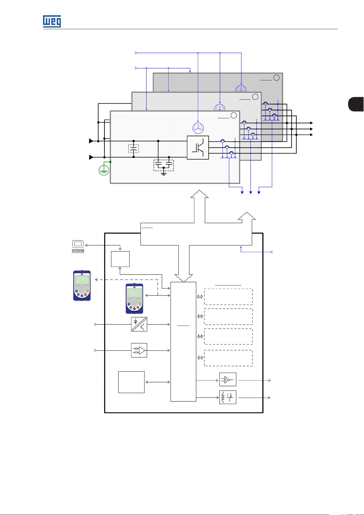
The UP11s and UC11 G2 are supplied trough a power supply of +24 Vdc. Figure 2.1 on page 2-5 shows a general
diagram of the inverter, considering the configuration with three UP11s connected in parallel.
The control of the power units is done by the UC11 G2 control unit. The control unit contains the control rack of
the CFW-11 line and the ICUP board. This board sends signals to all UP11 G2 (PWM, control signals, etc.), and it
receives signals from them (current, voltage feedback, etc.).
2-4 | CFW-11M G2
Page 15
DC supply
220 Vac power
supply external fans
24 Vac power
supply external fans
DC+
DC-
PE
Capacitor
brank
Power unit
RFI Filter
IGBT'S
PWM
IGBT'S
Fans
UP11
Fans
1
Fans
2
UP11
Feedback:
- voltage
- current
General Information
3
UP11
U
V
Motor
W
2
PC
Software SuperDrive G2
Software WLP
HMI (remote)
Digital inputs
(DI1 to DI6)
Analog inputs
(AI1 to AI6)
Power
Control
USB
memory
module
FLASH
ICUP
HMI
Power supplies and interfaces
between power and control
Accessories
Expansion I/O
(slot 1 - white)
Encoder interface
CC11
Control
board with
a 32 bits
"RISC"
CPU
(slot 2 - yellow)
COMM 1
(slot 3 - green)
COMM 2
(anybus) (slot 4)
External 24
Vdc power
electronics UC11
Analog outputs
(AO1 and AO2)
Digital outputs DO1
(RL1) to DO3 (RL3)
Figure 2.1: Block diagram for the CFW-11M G2
CFW-11M G2 | 2-5
Page 16
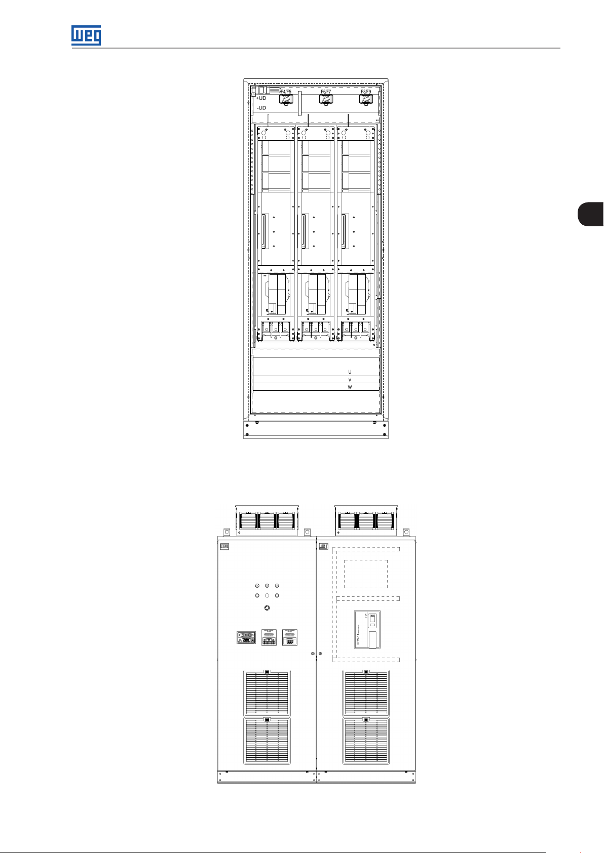
General Information
2
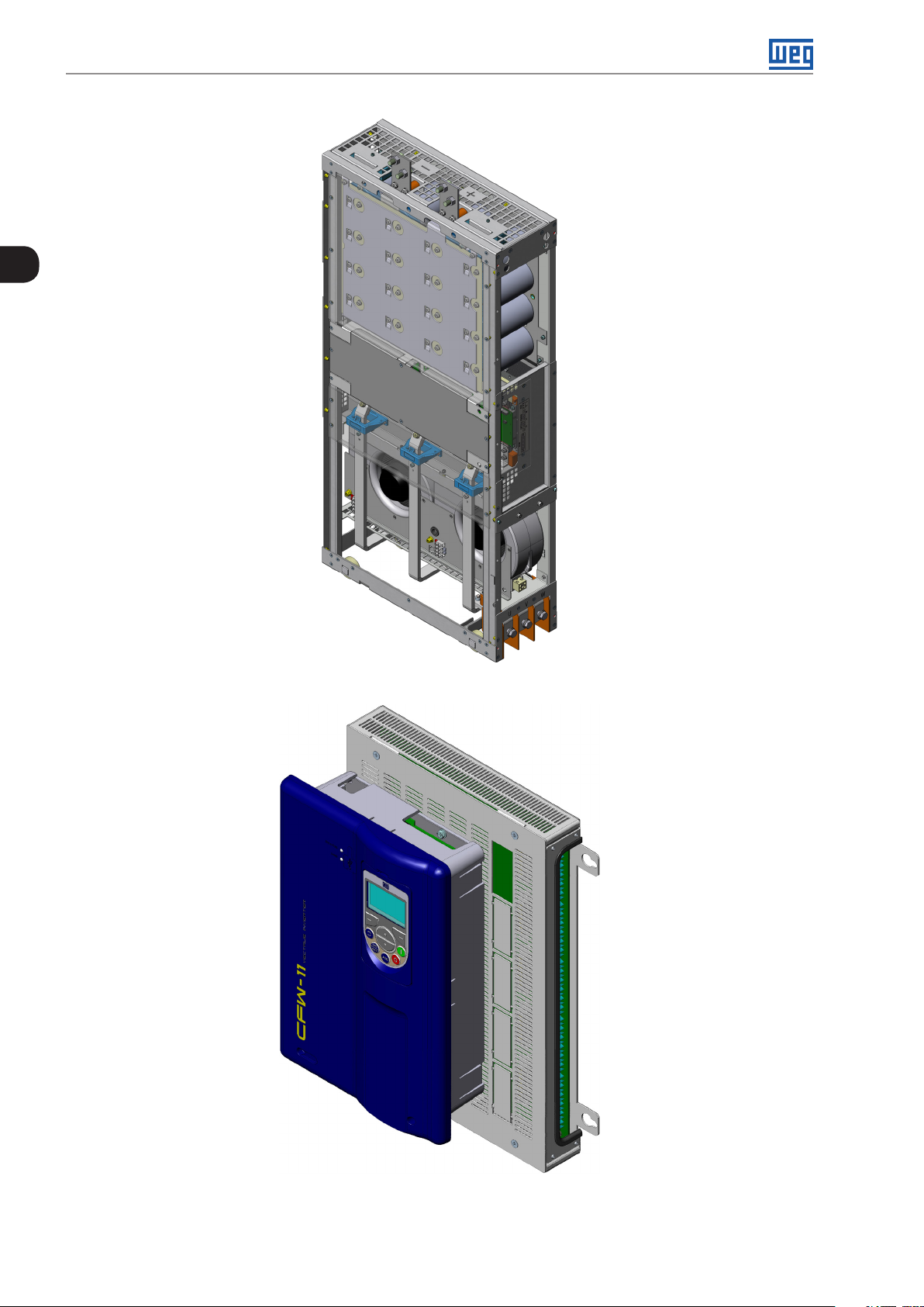
Figure 2.2: Power Unit (UP11)
2-6 | CFW-11M G2
Figure 2.3: Control Unit (UC11)
Page 17
General Information
NOTE!
Several additional items are necessary for mounting the complete drive, such as input rectifier, fuses
in the DC supply of each power unit UP11, external pre-charge circuit and an input reactor with a
minimum impedance of 3 % in case of a 6 pulse rectifier.
NOTE!
The inclusion of a current transformer (CT) in the drive for the output short-circuit to the ground
protection is not necessary because each UP11 has its own internal protection.
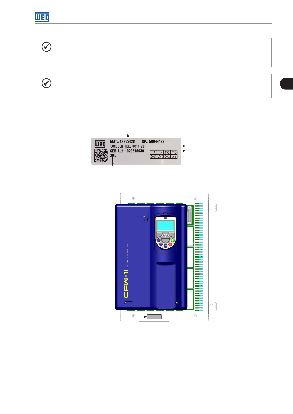
2.4 IDENTIFICATION LABEL FOR THE UC11 G2
The UC11 nameplate is located on the control rack.
WEG part number
Manufacturing date (30
corresponds to the week
and L to the year)
Figure 2.4: Nameplate of the UC11
2
UC11 model
Serial number
Nameplate
Figure 2.5: Nameplate location
CFW-11M G2 | 2-7
Page 18
General Information
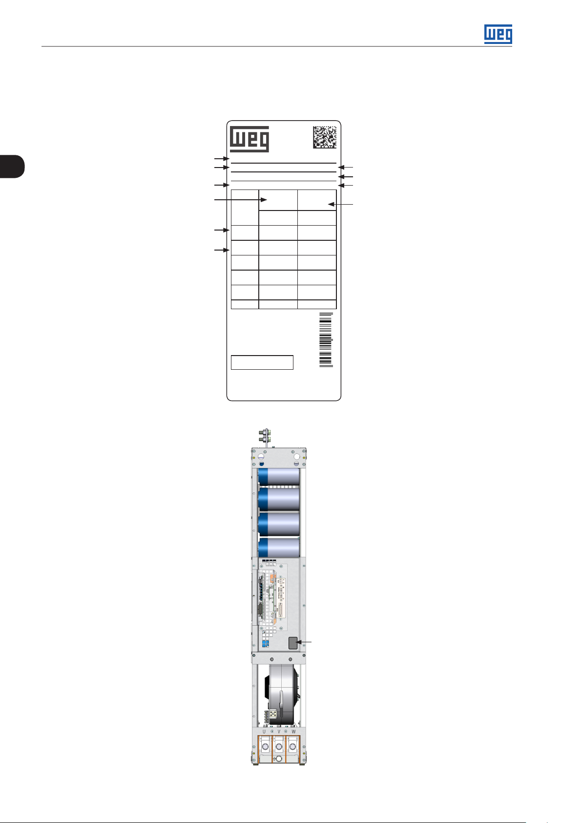
2.5 IDENTIFICATION LABEL FOR THE UP11 G2
The nameplate is located on the front of the UP11 G2.
Model of the UP11
2
WEG part number
Inverter net weight
Rated input data (voltage, rated
currents for operation with normal
duty and heavy duty, frequency)
Current specifications for
operation with normal duty (ND)
Current specifications for
operation with heavy duty (HD)
MOD.: UP11-01 G2
MAT.: 13353741 MAX. TA: 40 ºC (104 °F)
OP.: 8888888888 SERIAL#: 8888888888
PESO/WEIGHT: 94 kg (42,6 lb) 12 0
LINK DC
574-970 V DC
A (ND)
60s/3s
A (HD)
60s/3s
A (HD)
60s/3s
A (HD)
60s/3s
Hz 50/60 Hz 0-200 Hz
FABRICADO NO BRASIL
HECHO EN BR ASIL
MADE IN BR AZIL
WEG, CP420 - 89256-900
Jaraguá d o Sul - Brazil
570 A
437 A
758-1150 V DC
505 A
390 A
UP 11-0 1 G2
13353741
SERIAL#: 8888888888
OUTPUT
SALIDA
SAÍDA
0-0,71*VDC
VAC 3~
496 A
496 A / 744 A
380 A
570 A / 760 A
0-0,71*VDC
VAC 3~
439 A
483 A / 744 A
340 A
570 A / 680 A
12 0
Manufacturing date (48 corresponds
to the week and H to the year)
Serial number
Maximum ambient temperature
around the inverter
Rated output data (voltage, number of
phases, rated currents for operation
with normal duty (ND) and heavy duty
(HD), overload currents for 1 min and
3 s and frequency band)
7 90 9322 1388 93
Figure 2.6: UP11 G2 nameplate
2-8 | CFW-11M G2
Nameplate
Figure 2.7: Location of the Nameplates
Page 19
General Information
2.6 HOW TO SPECIFY THE MODEL OF THE CFW-11M G2 (SMART CODE)
In order to specify the model of the CFW-11M G2, replace the smart code values with the desired rated supply
voltage and rated output current in the respective fields for operation under normal duty (ND), as shown in the
example of Table 2.1 on page 2-9.
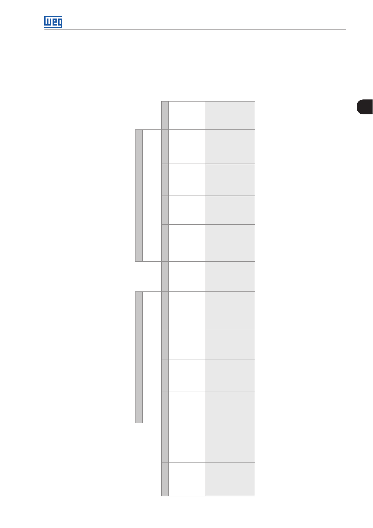
Table 2.1: Smart code
Final coding
indicator
digit
Special
software
Blank =
standard
S1 = special
sof tware #1
2
Inverter Model Available Options
hardware
details on the optional items
See Chapter 7 ACCESSORIES on page 7-1 for further
Braking Safety stop Special
S _ _ _ _ _ _ _ _ Z
Optional
items
(*)
Rated output
voltage
Number
of output
phases
Blank =
Y = with
Blank =
S =
4 = 380...480 V
standard
safety stop
standard
standard
5 = 500...600 V
phase
H1 = special
according
(no internal
product
6 = 660...690 V
hardware #1
to EN-954-
dynamic
O =
1 category
3
braking)
RB =
regenerative
braking
Product
with
optional
item
Rated
output
current for
use under
normal duty
(ND)
technical specifications of the inverters
See the list of models in Chapter 8 TECHNICAL
SPECIFICATIONS on page 8-1, which also contains the
WEG
frequency
inverter -
se r ie s 11
Market
identification
(sets the
language of the
manual and
factory settings)
2 characters T = Three-
Example BR CF W11MG2 0634 T 4
Field
denomination
Possible
options
CFW-11M G2 | 2-9
Page 20
General Information
E.g.: CFW11MG21205T4OYZ corresponds to a CFW-11M G2 three-phase inverter of 1205 A, with input supply
voltage from 380 V to 480 V, with optional safety stop. The options for the inverter rated current under normal
duty (ND) are in Table 3.2 on page 2-10, according to the inverter rated output voltage.
Table 3.2: Rated currents under normal duty (ND)
380-480 V 500-600 V 660 -690 V
0634 = 634 A 0496 = 496 A 0439 = 439 A
2
1205 = 1205 A 0942 = 942 A 0834 = 834 A
1807 = 1807 A 1414 = 1414 A 1251 = 1251 A
2409 = 2409 A 1885 = 1885 A 1668 = 1668 A
3012 = 3012 A 2356 = 2356 A 2085 = 2085 A
2.7 RECEIPT AND STORAGE
The power units of the CFW-11M G2 are supplied in a wooden box.
The control units of the CFW-11M G2 are supplied in a cardboard box.
There is an identification label affixed to the outside of the package, the same as the one fixed on the inverter.
In order to open the package:
1. Remove the front cover of the package.
2. Remove the styrofoam protection.
Check if:
1. The nameplates correspond to the models purchased.
2. There were any damages during transportation.
Report any damage immediately to the carrier.
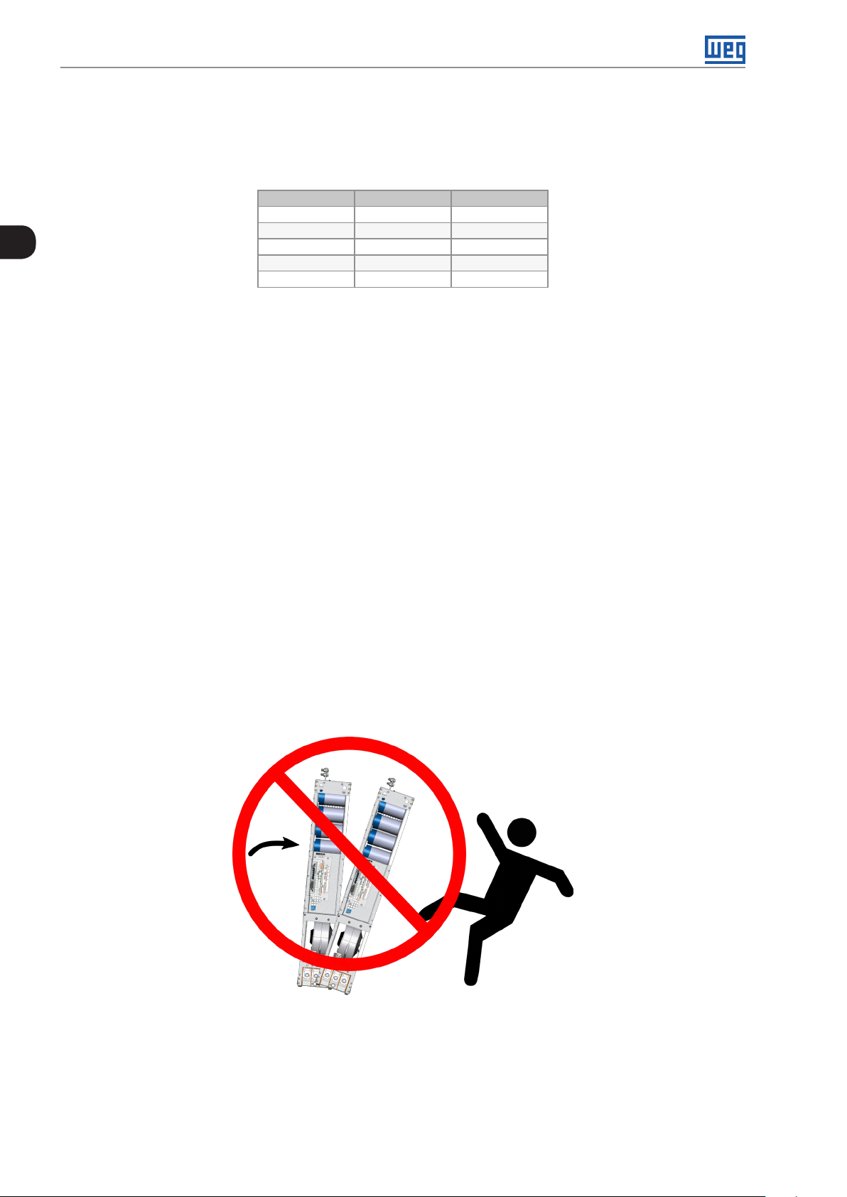
If the products are not immediately installed , store them in a clean and dry location (temperature between –
25 ºC and 60 ºC), with a cover to prevent the ingress of dust.
2-10 | CFW-11M G2
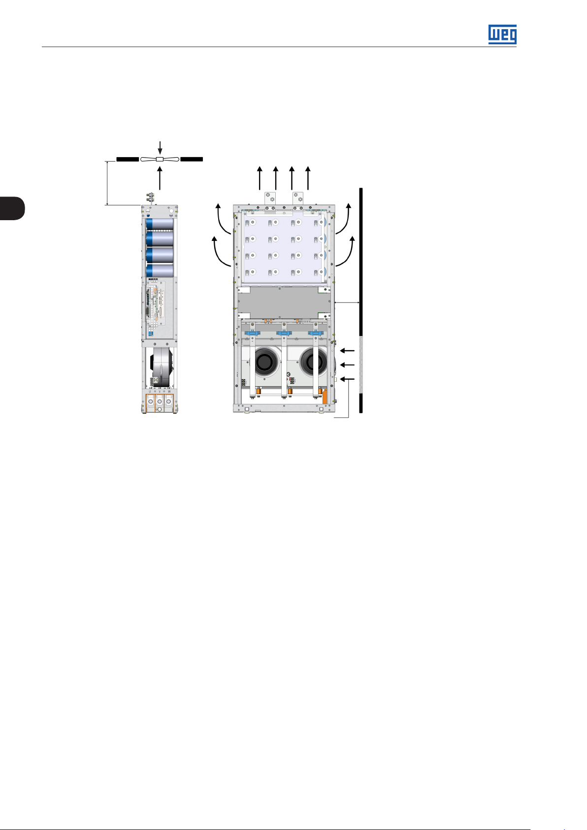
Figure 2.8: Do not tilt the power units
Page 21

Installation and Connection
3 INSTALLATION AND CONNECTION
This chapter provides information on installing and wiring the CFW-11M G2. The instructions and guidelines listed
in this manual shall be followed to guarantee personnel and equipment safety, as well as the proper operation of
the inverter.
3.1 MECHANICAL INSTALLATION
The power units must be installed in the drive panel appropriately, allowing easy extraction and reinstallation in
case of maintenance. The mounting must be such to avoid damage during the panel transportation.
3.1.1 Environment Conditions
Avoid:
Direct exposure to sunlight, rain, high humidity, or sea-air.
Inflammable or corrosive liquids or gases.
Excessive vibration.
Dust, metal particles or oil suspended in the air.
Environment conditions for the operation of the inverter:
Ambient temperature: 0 °C to 45 °C (32 °F to 113 °F) - rated conditions (measured around the inverter). From
45 ºC to 55 ºC (113 °F to 131 °F) - 2 % of current derating for each Celsius degree above 45 ºC (113 °F).
Altitude: up to 1000 m (3.300 ft) above sea level – rated conditions.
From 1000 m to 4000 m (3.300 ft to 13.200 ft) – 1% of current derating for each 100 m (330 ft) above 1000 m
(3.300 ft) of altitude.
From 2000 m to 4000 m (6.600 ft to 13.200 ft) - maximum voltage (480 V for models 380...480 V and 690 V for
models 500...690 V) derating of 1.1 % for each 100 m (330 ft) above 2000 m (6.600 ft).
3
Maximum altitude of up to 4000 m (13.200 ft).
Air relative humidity: 5 % to 95 % non-condensing.
Pollution degree: 2 (according to EN50178 and UL508C), with non-conductive pollution. Condensation must
not cause conduction of the accumulated residues.
3.1. 2 List of Components
For panel mounting of the CFW11M G2, it is necessary: a control set (UC11 G2), UP11 G2 power units and a cable
set to connect the UC11 G2 to the UP11 G2. Table 3.1 on page 3-1, Table 3.2 on page 3-2 and Table 3.3 on
page 3-2 present the list of components of the CFW-11M G2 inverter.
Table 3.1: List of Components - Drives CFW-11M G2 380 - 480 V
Qt y.
UP 11- 0 2 G2
1 634 515 1 1 - 2 1205 979 1 2 - 3 1807 146 8 1 - 1 2
4 2409 1957 1 2 1 1
5 3012 2446 1 - 3 2
Rated Current [A]
ND HD
Qty. UC11 G2
Qty. Cable Set
2.5 m
Qty. Cable Set
3.0 m
Qty. Cable Set
3.6 m
CFW-11M G2 | 3-1
Page 22
Installation and Connection
Table 3.2: List of Components - Drives CFW-11M G2 500 - 600 V
Qt y.
UP 11- 0 2 G2
1 496 380 1 1 - 2 942 722 1 2 - 3 1414 1083 1 - 1 2
4 1885 1444 1 2 1 1
5 2356 1805 1 - 3 2
Qt y.
3
UP 11- 0 2 G2
1 439 340 1 1 - 2 834 646 1 2 - 3 1251 969 1 - 1 2
4 1668 1292 1 2 1 1
5 2085 1615 1 - 3 2
Rated Current [A]
ND HD
Table 3.3: Lista de componentes acionamentos CFW-11M G2 660 - 690 V
Rated Current [A]
ND HD
WEG Item Cable Set
13555095 2.5 m Cables
13555150 3.0 m Cables
135 55151 3.6 m Cables
Qty. UC11 G2
Qty. UC11 G2
Table 3.4: Cable set items
Qty. Cable Set
2.5 m
Qty. Cable Set
2.5 m
Qty. Cable Set
3.0 m
Qty. Cable Set
3.0 m
Qty. Cable Set
3.6 m
Qty. Cable Set
3.6 m
The other components of the drive are under the responsibility of the panel builder. Among those components, we
may point out the input rectifier, power busbar, pre-charge circuit, panel fans, protection fuses, input reactance, etc.
3-2 | CFW-11M G2
Page 23
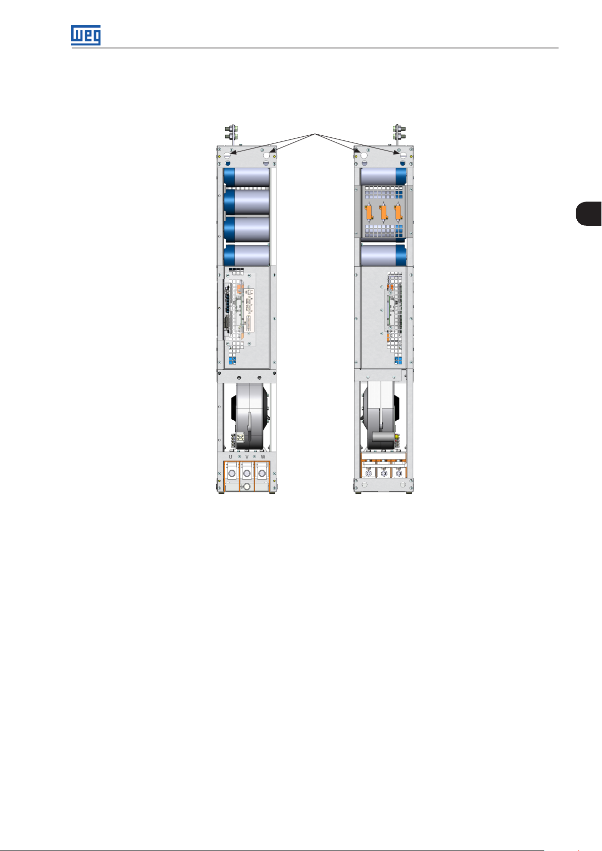
3.1.3 Lifting
Figure 3.1 on page 3-3 shows the position of the lifting lugs.
Lifting lugs
Installation and Connection
3
Front view Back View
Figure 3.1: UP11 G2 lifting lugs
CFW-11M G2 | 3-3
Page 24
Installation and Connection
3.1.4 Panel Ventilation
The efficiency of the panel ventilation depends on the equipment installed inside the panel, such as fans, air inlets
and filters. The internal fan of the UP11 is not enough to cool the entire panel.
Panel fan (when required)
Air outlets
Air outlet
[10.0] 250
3
[6.0]
150
Ventilation openings on the
front surface of the panel
Air inlet
Figure 3.2: Clearances for ventilation in mm [in]
The total air flow of the fans of the power unit is 1150 m3/h (320 l/s; 677 CFM).
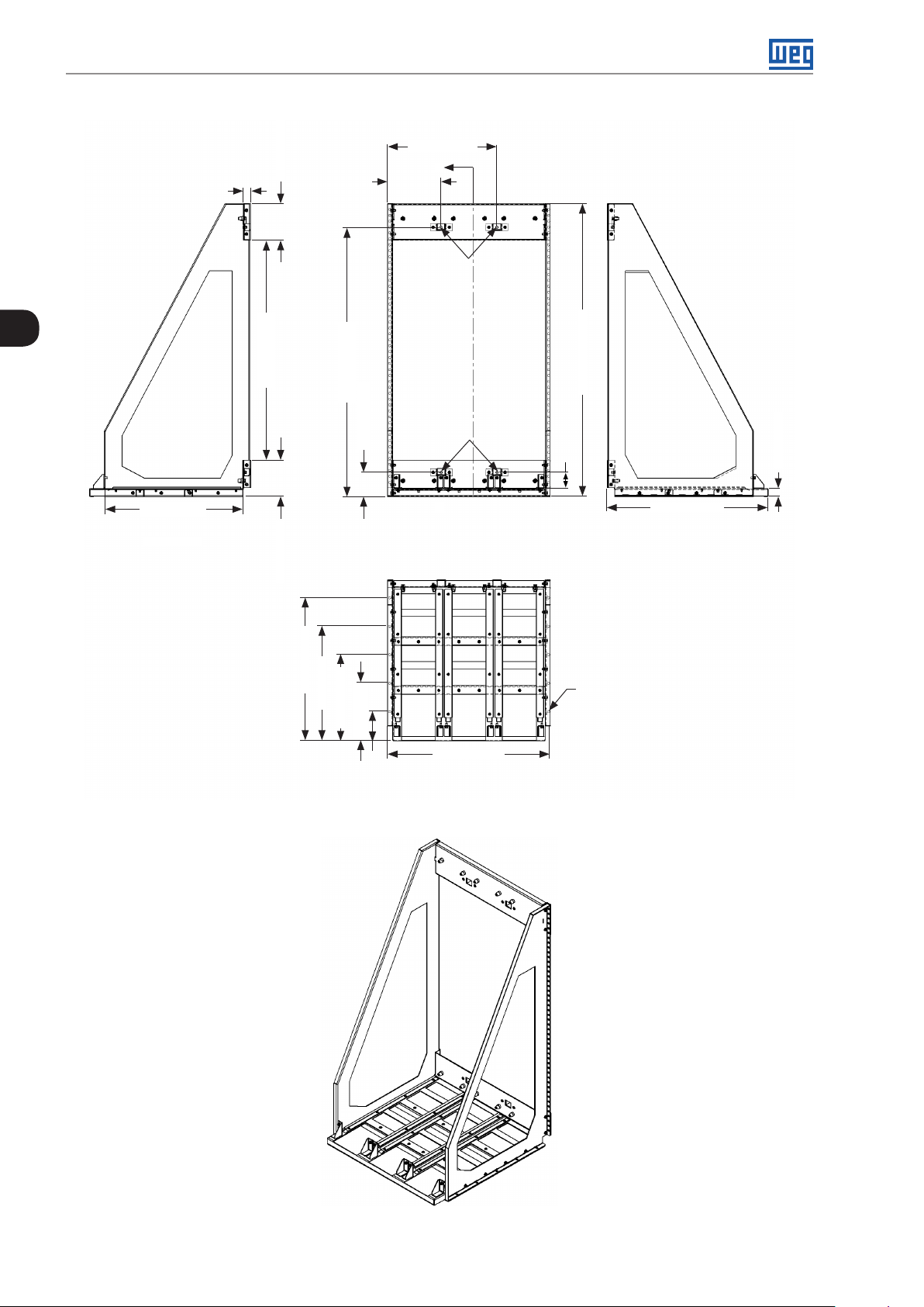
3.1.5 Panel Mounting of the UP11 G2
To install the UP11 G2 in panels, the following mounting accessories are necessary:
Rack 2 G2 allows the mounting of 1 or 2 modules side by side in 600 mm wide panels.
Rack 3 G2 allows the mounting of 1, 2 or 3 modules side by side in 800 mm wide panels.
3-4 | CFW-11M G2
Page 25

30.1 [1.19]
Installation and Connection
354.7 [13.96]
A
119.7 [4.71]
ø9.2 [0.36]
15 5 . 2 [6.11]
3
582 [22.91]
A-A
926.7 [36.48]
152.6 [6.01]
602.5 [23.72]
482.5 [19]
1134.5 [44.67]
1079.3 [42.49]
ø9.2 [0.36]
69.9 [2.75]
A
36 2.5 [14.27]
242.5 [9.55]
474.4 [18 . 6 8]
122.5 [4.82]
102.5 [4.04]
32.6 [1. 28]
678.8 [26.72]
ø9.2 [0.36]
Figure 3.3: Dimensions of Rack 2 G2 in mm [in]
CFW-11M G2 | 3-5
Page 26
Installation and Connection
459.6 [18 .1]
15 5 . 2 [6.11]
30.1 [1.19]
A
224.6[8.84]
ø9.2 [0.36]
3
582 [22.93]
A-A
926.7 [36.48]
1134.5 [44.67]
ø9.2 [0.36]
102.5 [4.04]
A
152.6 [6.01]
602.5 [23.72]
482.5 [19]
36 2.5 [14.27 ]
36 2.5 [14. 27]
684.7 [26.96]
122.5 [4.82]
1234.5 [48.6]
68.3 [2.69]
ø9.2 [0.36]
32.6 [1. 28]
678.8 [26.72]
3-6 | CFW-11M G2
Figure 3.4: Dimensions of Rack 3 G2 in mm [in]
Page 27
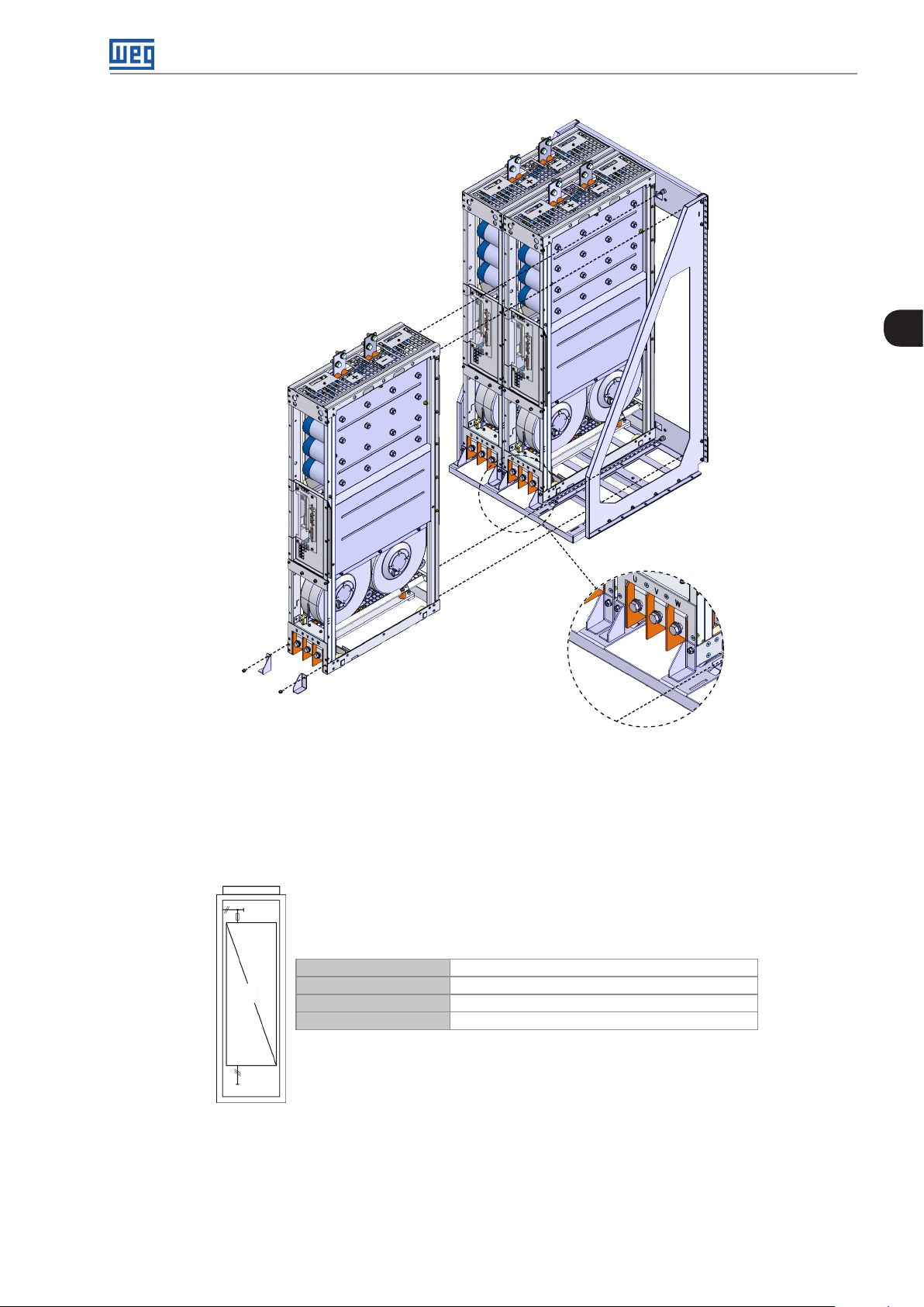
Installation and Connection
3
Figure 3.5: Insertion of the power modules into Rack 3 G2
3.1.6 Panel
According to the quantity of UP11 G2 of the drive, minimum dimensions are necessary for the panels. Figure 3.6
on page 3-7, Figure 3.7 on page 3-8, Figure 3.8 on page 3-8 and Figure 3.10 on page 3-8 present the
minimum dimensions of the panel according to the quantity of UP11 G2.
Panel Width At least 600 mm
1
Panel Height At least 2000 mm
Panel Depth At least 800 mm
Weight Capacity 118 kg
Figure 3.6: Data of the panel for drive with 1 UP11 G2
CFW-11M G2 | 3-7
Page 28
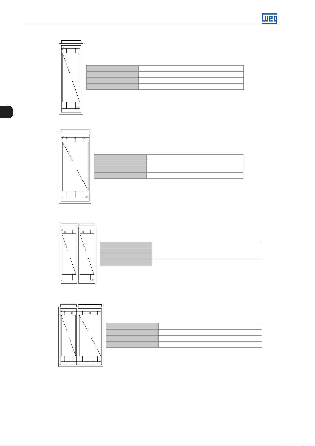
Installation and Connection
Panel Width At least 600 mm
2
Panel Height At least 2000 mm
Panel Depth At least 800 mm
Weight Capacity 212 kg
3
Figure 3.7: Data of the panel for drive with 2 UP11 G2
Panel Width At least 800 mm
3
Panel Height At least 2000 mm
Panel Depth At least 800 mm
Weight Capacity 310 kg
Column A Column B
2
Column A Column B
2 3
2
Figure 3.8: Data of the panel for drive with 3 UP11 G2
Panel Width At least 600 mm (Column A) + 600 mm (Column B)
Panel Height At least 2000 mm
Panel Depth At least 800 mm
Weight Capacity 212 kg (Column A) + 212 kg (Column B)
Figure 3.9: Data of the panel for drive with 4 UP11 G2
Panel Width At least 600 mm (Column A) + 800 mm (Column B)
Panel Height At least 2000 mm
Panel Depth At least 800 mm
Weight Capacity 212 kg (Column A) + 310 kg (Column B)
3-8 | CFW-11M G2
Figure 3.10: Data of the panel for drive with 5 UP11 G2
Page 29
Installation and Connection
3
Figure 3.11: Column with 3 UP11 G2 installed
Mounting of the UC11 at the panel door: Control rack with flange mounting and IPS1 module mounted at the
bottom part of the door. The control rack is secured with four M3 screws (tightening torque: 0.5 Nm).
ICUP
Figure 3.12: Example of mounting of the control rack in the panel
CFW-11M G2 | 3-9
Page 30
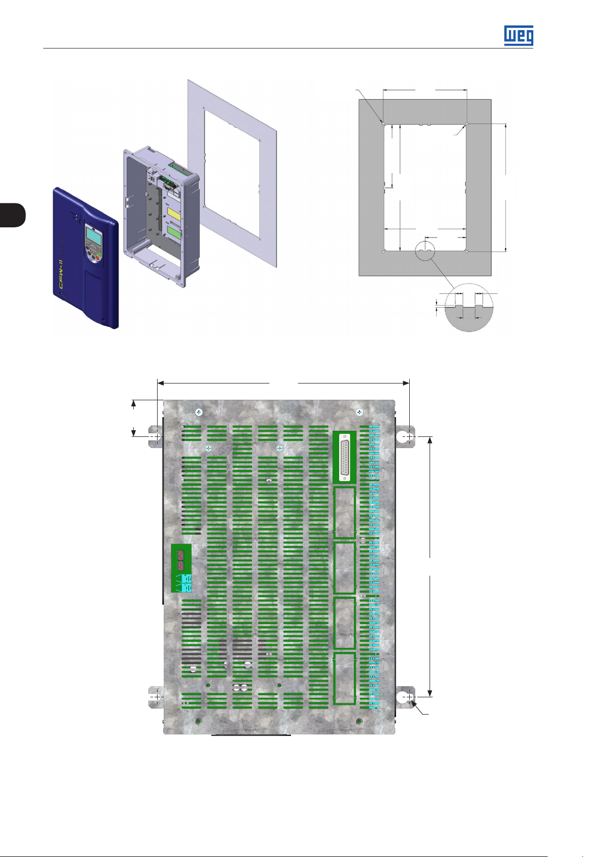
Installation and Connection
ø 5.2 (4X)
(0.20)
3
Figure 3.13: Mounting of the control rack and necessary slots mm (in)
[11. 2]
283.6
190
(7. 4 8)
R8 (4x)
(0.32)
(5.64)
143.3
286.5
(11.28)
186.5
(7.34)
7 (0.27)
93.3
(3.67)
11
(0.43)
2 (0.08)
290
(11.42)
7 (0.27)
[1.6]
41.5
292
[11. 5]
[0.2]
R4 (4x)
Figure 3.14: Mounting of the base of the ICUP1 module (mm)
The shield of the ICUP board is mounted with four screws M6 (recommended torque: 8.5 N.m).
3-10 | CFW-11M G2
Page 31

3.2 ELECTRICAL INSTALLATION
DANGER!
The following information is merely a guide for proper installation. Comply with applicable local
regulations for electrical installations.
DANGER!
Les informations suivantes constituent uniquement un guide pour une installation correcte. Respectez
les réglementations locales en vigueur pour les installations électriques.
DANGER!
Make sure the AC power supply is disconnected before starting the installation.
DANGER!
Vérifiez que l'alimentation secteur CA est débranchée avant de commencer l'installation.
Installation and Connection
3
ATTENTION!
The CFW-11M G2 can be connected in circuits with symmetrical short circuit capability up to 100000
A
(480 V/690 V maximum).
rms
ATTENTION!
Integral solid state short circuit protection does not provide branch circuit protection. Branch circuit
protection must be provided in accordance with applicable local codes.
3. 2 .1 Input Rectifier
It is necessary to use a rectifier to generate DC voltage for the power supply of the UP11 G2. The rectifier may be
an Active Front End (AFE) or a diode bridge rectifier with 6, 12, 18 pulses or more.
The following items contain general directions on the sizing of a 6-pulse rectifier. For further information on multipulse
rectifiers or AFE solution, contact WEG.
3. 2 .1.1 Sizing
The main rectifier bridge is selected to comply with the nominal power of the drive. The heat dissipation caused
by losses at the rectifier bridge should be taken into account for the sizing of the heatsink, as well as in the heating
up of the panel internal air.
ATTENTION!
The diodes reverse voltage must be ≥ 2200 V.
3.2.1.2 Line Reactor
The diode rectifier plus the capacitor bank of the UP11 G2 drain from the electric grid a current with non-sinusoidal
wave shape containing harmonics of the fundamental frequency. Those harmonic currents flowing on the
impedances of the power supply line cause harmonic voltage drops, distorting the supply voltage of the inverter
itself and other loads connected to this line. These harmonic current and voltage distortions may increase the
electrical losses in the installation, overheating components (cables, transformers, capacitor banks, motors, etc.),
as well as a lowering power factor.
CFW-11M G2 | 3-11
Page 32

Installation and Connection
The harmonic input currents depend on the impedance values that are present in the rectifier input/output circuit.
The addition of a line reactor and/or DC bus choke reduces the current harmonic content, providing the following
advantages:
Increased input power factor.
Reduced RMS input current.
Reduced power supply voltage distortion.
Increased life of the DC Link capacitors.
3
To determine the line reactor needed to obtain the desired voltage drop, use equation below:
Voltage Drop [%] x Line Voltage [V]
L
=
line
3 x 2π x Line Freq [Hz] x Rated Cur . [A]
ATTENTION!
It is recommended a line reactance of at least 3 % on the input of the 6-pulse diode rectifier.
3. 2 .1.3 Pre-Charge
The resistors of the pre-charge circuit must be sized according to the following criteria:
Maximum voltage.
Maximum energy.
Power overload capacity of the resistors during the pre-charge period (energy dissipation capacity).
Table 3.5: Dimensioning of the pre-charge
Peak Current During the Pre-charge (A) 0.82.(V
Energy Stored in the Capacitor Bank (J)
Duration of the Pre-charge (s)
UP11- 02 G 2 N.0.012.V
UP11- 01 G2 N.0.006.V
UP11- 02 G 2 0.031.N.R
UP11- 01 G2 0.015.N.R
Where R is the ohmic value of the resistor used on each phase and N the number of power units.
Example:
At a drive composed by three power units, whose line voltage at the input of the rectifier was 690 Vrms
(UP11-01 G2), the obtained values would be the following:
Energy stored in the capacitor bank: 3.0,006.6902 = 8569.8 J.
/R)
line
2
line
2
line
Using three 10 Ω resistors (one per phase), each resistor must withstand 2856.6 J.
The resistor manufacturer is able to inform the power supported by the component.
The peak current during the pre-charge would be 56.6 A and the length of the pre-charge would be 0.45 s.
3-12 | CFW-11M G2
Page 33

K1
Line Reactor
Installation and Connection
Rectifier UP11 G 2
DC+
U
Rede
KPCR
220 Vac
external
R
11
Stop
12
11
S
off
12
CC11 (D O1)
1313
S
KA1
on
+RC
KA1
A1 A1 A1
A2 A2 A2 A2 A2
15
KT1 KA2
16
18 14
43
KA1
44
XC1:22
XC1:22XC1:23
211414
KPCR
22 22
KA2 KPCR
KA2
DC-
13
KA2
21
A1 A1
K1RT1
43
44
V
W
Motor
3
Figure 3.15: Pre-charge circuit example
The CFW-11M G2 input rectifier can be supplied through a contactor or a motorized circuit breaker (represented
by K1), whose command must be interlocked with the pre-charge contactor K(PCR) command. The Figure 3.15
on page 3-13 presents an example of the recommended pre-charge circuit for the CFW-11M G2 inverter, with
simplified power and command diagrams. The digital relay output DO1 of the CC11 board must be configured
with the “Pre-Charge OK” function (P0275 = 25). This relay must be used to command the pre-charge contactor
and the main contactor (motorized circuit breaker). Furthermore, the pre-charge length must be timed for the
protection of the auxiliary circuit (resistors, rectifier bridge). This function is carried out by a timer with a normallyclosed on-delay contact, represented in Figure 3.15 on page 3-13 by RT1.
CFW-11M G2 | 3-13
Page 34

Installation and Connection
3. 2 .1.4 Harmonics of the 6-Pulse Rectifier
Table 3.6 on page 3-14, Figure 3.16 on page 3-14 and Figure 3.17 on page 3-14 show the typical values of the
harmonic content of the currents, Power Factor (PF) and THD (I) on the power supply, considering the 6-pulse
rectifier.
Table 3.6: Individual harmonics, Power Factor and THD (I) typical for rated load in the output, 6-pulse rectifier
Harmonic
Order
1 100.0 %
5 38.7 %
3
40 %
35 %
7 14.1 %
11 6.7 %
13 3.3 %
17 2.9 %
19 1.9 %
23 1.4 %
I (%) FP THD(I)
0,89 42 %
30 %
25 %
20 %
15 %
10 %
Normalized Harmonic Amplitude
5 %
0 %
0 % 20 % 40 % 60 %
Load percentage
Note: Amplitude of the normalized harmonics as a function of the fundamental with 100 % of load. 6-pulse rectifier.
Figure 3.16: Typical values of the harmonics of the input current with variation of the output power
3,0 %
2,5 %
2,0 %
1,5 %
1,0 %
Normalized Harmonic Amplitude
0,5 %
80 % 100 %
5th Harmonic
7th Harmonic
11th Harmonic
13th Harmonic
17th Harmonic
19th Harmonic
23th Harmonic
120 %
5th Harmonic
7th Harmonic
11th Harmonic
13th Harmonic
17th Harmonic
19th Harmonic
23th Harmonic
0,0 %
0 %
3-14 | CFW-11M G2
20 % 40 % 60 % 80 % 100 % 120 %
Load percentage
Figure 3.17: Power Factor (FP) and THD(I) with variation of the output power 6-pulse rectifier
Page 35

Installation and Connection
3.2.1.5 Harmonics of the 12-Pulse Rectifier
Table 3.7 on page 3-15, Figure 3.18 on page 3-15 and Figure 3.19 on page 3-15 show the typical values of the
harmonic content of the currents, Power Factor and THD (I) on the power supply, considering the 12-pulse rectifier.
Table 3.7: Individual harmonics, Power Factor and THD (I) typical for rated load in the output, 12-pulse rectifier
Harmonic
Order
1 100.0 %
5 0.0 %
7 0.0 %
11 6.0 %
13 3.2 %
17 0.0 %
19 0.0 %
23 1.1 %
7 %
6 %
I (%) FP THD(I)
0,96 7,1 %
3
5 %
4 %
3 %
2 %
Normalized Harmonic Amplitude
1 %
0 %
Note: Amplitude of the normalized harmonics as a function of the fundamental with 100 % of load. 12-pulse rectifier.
0.97 12 %
0.968 11 %
0.966 10 %
20 % 40 % 60 % 80 % 10 0 % 120 %0 %
Load percentage
Figure 3.18: Typical values of the harmonics of the input current with variation of the output power
5th Harmonic
7th Harmonic
11th Harmonic
13th Harmonic
17th Harmonic
19th Harmonic
23th Harmonic
0.964
Power Factor
0.962 8 %
0.96 7 %
0.958
20 % 40 % 60 % 80 % 100 % 120 %0 %
Figure 3.19: Power Factor (FP) and THD (I) with variation of the output power. 12-pulse rectifier
Load percentage
CFW-11M G2 | 3-15
9 %
6 %
THD
Page 36

Installation and Connection
3.2.1.6 Harmonics of the 18-Pulse Rectifier
Table 3.8 on page 3-16, Figure 3.20 on page 3-16 and Figure 3.21 on page 3-16 show the typical values of the
harmonic content of the currents, Power Factor and THD (I) on the power supply, considering the 18-pulse rectifier.
Table 3.8: Individual harmonics, Power Factor and THD (I) typical for rated load in the output, 18-pulse rectifier
Harmonic
Order
1 100.0 %
5 0.2 %
7 0.0 %
3
3,0 %
2,5 %
11 0.1 %
13 0.0 %
17 2.5 %
19 1.9 %
23 0.0 %
I (%) FP THD(I)
0.97 3.2 %
2,0 %
1,5 %
1,0 %
Normalized Harmonic Amplitude
0,5 %
0,0 %
0 %
Note: Amplitude of the normalized harmonics as a function of the fundamental with 100 % of load. 18-pulse rectifier.
0.971
0.97
0.969
20 % 40 % 60 % 80 % 100 % 120 %
Load percentage
Figure 3.20: Typical values of the harmonics of the input current with variation of the output power
5th Harmonic
7th Harmonic
11th Harmonic
13th Harmonic
17th Harmonic
19th Harmonic
23th Harmonic
6.0 %
5.5 %
5.0 %
0.968
Power Factor
0.967
0.966
0.965
0 %
3-16 | CFW-11M G2
20 % 40 % 60 % 80 % 100 % 120 %
Load percentage
Figure 3.21: Power Factor (FP) and THD (I) with variation of the output power 18-pulse rectifier
4.5 %
4.0 %
3.5 %
3.0 %
THD
Page 37

Installation and Connection
NOTE!
The harmonics shown in Item 3.2.1.4 Harmonics of the 6-Pulse Rectifier on page 3-14, Item 3.2.1.5
Harmonics of the 12-Pulse Rectifier on page 3-15 and Item 3.2.1.6 Harmonics of the 18-Pulse Rectifier
on page 3-16 are typical values and may vary according to the application. The data shown are
valid for the following condition:
Short circuit current of the transformer of 100000 symmetric Arms.
Line reactance of 3 %.
3.2.2 Busbars
The panel busbars must be sized according to the rectifier output current and the drive output current. It is
recommended to use copper busbars. In case it is necessary to use aluminum busbars, it is necessary to clean
the contacts and use anti-oxidant compound. If the compound is not used, any copper and aluminum joint will
undergo accelerated corrosion.
3.2.3 Fuses
It is recommended to use proper fuses for operation in direct current on the DC power supply of the UP11 G2. The
maximum voltage on the DC link on the UP11-01 G2 is 1200 Vdc, on the UP11-02 G2 is 800 Vdc (tripping level
of the IGBTs for overvoltage). Fuses used in AC lines can be used, but the specified AC voltage must be derated.
To obtain the derating factor, refer to the fuse manufacturer.
3
Examples of fuses:
UP11-01 G2: PC73UD13C630TF (Mersen).
UP11-02 G2: PC73UD12C900TF (Mersen).
3.2.4 General Wiring Diagram
Figure 3.22 on page 3-18 shows the general diagram for an inverter with five power units (UP11). It shows the
connections between the Control Unit UC11 and the UPs (XC40 DB25 connectors and optical fibers), power
connections of the UPs (DC+, DC-, U, V, W and GND), and auxiliary power supply connections of the cooling
(220 V), of the UP11 (24 Vdc) and UC11 (24 Vdc). For a reduced number of UP11, connect them in increasing order
(1, 2, 3, etc.), leaving the last positions without connection.
CFW-11M G2 | 3-17
Page 38

Installation and Connection
UC11
ICUP
XC40AUH1...WL1UH2...WL2UH3...WL3
+UD
-UD
+UD
-UD
UP11
U
V
W
XC33
1
220 Vac
3
XC6
1
2
1
2
3
24 Vdc
+UD
-UD
HMI
CC11
XC60
XC60XC9XC67XC5
UP11
U
V
W
1
2
3
24 Vdc
XC33
1
220 Vac
XC6
2
2
1
2
3
24 Vdc
+UD
UP11
24 Vdc
XC6
-UD
U
V
W
U
V
MOTOR
W
3
XC40C
stop
Safety
XC40 XC40 XC40
UH...WL UH...WL UH...WLUH...WLUH...WL
XC33
inputs
Digital
220 Vac
+UD
Dynamic
BR
Error_BR
Braking
XC40DXC40E
XC40XC40
UP11
-UD
U
V
XC6
W
4
UH4...WL4UH5...WL5 XC40B
XC33
3-18 | CFW-11M G2
220 Vac
24 Vdc
+UD
-UD
UP11
U
V
W
XC33
1 1 1
220 Vac
XC6
5
2 2 2
1 1 1
2 2 2
3 3 3
24 Vdc
Figure 3.22: General wiring diagram
Page 39

3.2.5 Power Connections
Power
supply DC
DC+ DC+ DC+DC- DC- DC-
Installation and Connection
3
U
V
W
PE
U U U
V V V
W W W
Figure 3.23: Power and grounding connections
ATTENTION!
The protective earth of the motor must be connected to the panel ground.
The fastening of the DC+ and DC- connections of the UP11 G2 is done with 4 screws M12X35 (tightening torque:
60 N.m); refer to the Figure 3.24 on page 3-20.
CFW-11M G2 | 3-19
Page 40

Installation and Connection
DC- DC+
3
Figure 3.24: DC power supply terminals
DC+: DC Link positive terminal.
DC-: DC Link negative terminal.
The U, V and W connections are made through 3 screws M12X45 (tightening torque: 60 N.m, see Figure 3.25 on
page 3-21).
The screw used to fasten the grounding cable of the UP11 G2 is M12X25 (tightening torque: 60 N.m).
3-20 | CFW-11M G2
Page 41

Installation and Connection
3
Figure 3.25: U, V, W and grounding terminals
U, V and W: Motor connection.
: Grounding connection.
For a better current distribution between the UP11, it is recommended that their output connections be
interconnected through a single paralleling busbar. The length of the cables between the UP11 and the paralleling
busbar must be as short as possible.
ATTENTION!
The output cables U, V and W of all paralleled UP11 must have the same length.
CFW-11M G2 | 3-21
Page 42

Installation and Connection
ATTENTION!
The motor cables must be distributed as evenly as possible on the connection to the paralleling
busbar, as in the example shown in Figure 3.26 on page 3-22. Distance "L" must be kept constant.
DC Power
Supply
DC+
DC+ DC+DC- DC- DC-
3
U
Grounding
busbar
Phase U
Phase V
Phase W
U
L
U U
W W W
LLLLL
L
L L L L
W
PE
L
Paralleling
busbar
Figure 3.26: Recommended distribution for the motor cables
3.2.6 Input Connections
DANGER!
Provide a disconnect device for the input power supply of the inverter.
This device shall disconnect the input power supply for the inverter when needed (for instance,
during servicing).
DANGER!
Montez un dispositif de coupure sur l'alimentation du variateur.
Ce composant déconnecte l'alimentation du variateur si cela est nécessaire (ex. pendant l'entretien
et la maintenance).
3-22 | CFW-11M G2
Page 43

Installation and Connection
ATTENTION!
A contactor or another device that frequently disconnects and reapplies the AC supply to the inverter,
in order to start and stop the motor, may cause damage to the inverter power section. The drive
is designed to use control signals for starting and stopping the motor. If used for that purpose, the
input device must not exceed one operation per minute; otherwise, the inverter may be damaged.
ATTENTION!
The supply voltage must not exceed the inverter rated values (see Table 8.1 on page 8-2).
The interconnection between the DC Link and each UP11 G2 can be done with flat braided cables according to
the Figure 3.27 on page 3-23, example, sized to withstand the DC Link current, according to the Table 8.1 on
page 8-2. The Figure 3.28 on page 3-23 shows an example of flexible braid used by WEG, using a fuse on
DC+ and another on DC-.
3
DC-
Figure 3.27: Side view of the connections of the flexible braids and fuses
26
(1.02)
17
(0.67)
17
(0.67)
26
(1.02)
60
(2.36)
Figure 3.28: Example of flat braided cable – mm (in)
F1 F1
E
Braided wire gauge: AWG-40
DC+
E
60
(2.36)
30
(1.18 )
ø 14 (3x)
(0.55)
25
(0.98)
8±1
50
(1.97)
NOTE!
It is important that all the flexible braids have the same length (defined by dimension “E”), which will
depend on the panel construction.
CFW-11M G2 | 3-23
Page 44
Installation and Connection
3.2.7 Output Connections
ATTENTION!
The inverter has an electronic motor overload protection that must be adjusted according to the
driven motor. When several motors are connected to the same inverter, install individual overload
relays for each motor.
ATTENTION!
The motor overload protection available on the CFW-11M G2 complies with IEC609047-4-2 and
3
UL508C, notice the information below:
Trip current equal to 1.25 times the motor rated current (P0401) set on the "Oriented Start-up" menu.
The maximum value of parameter P0398 (Motor Service Factor) is 1.15.
Parameters P0156, P0157 and P0158 (overload current at 100 %, 50 % and 5 % of the rated speed,
respectively) are automatically set when parameters P0401 (motor rated current) and/or P0406 (motor
cooling) are set on the "Oriented Start-up" menu. If parameters P0156, P0157 and P0158 are manually
set, the maximum value allowed is 1.05 x P0401.
ATTENTION!
If a disconnect switch or a contactor is installed between the inverter and the motor, never operate
it with a spinning motor or with voltage at the inverter output.
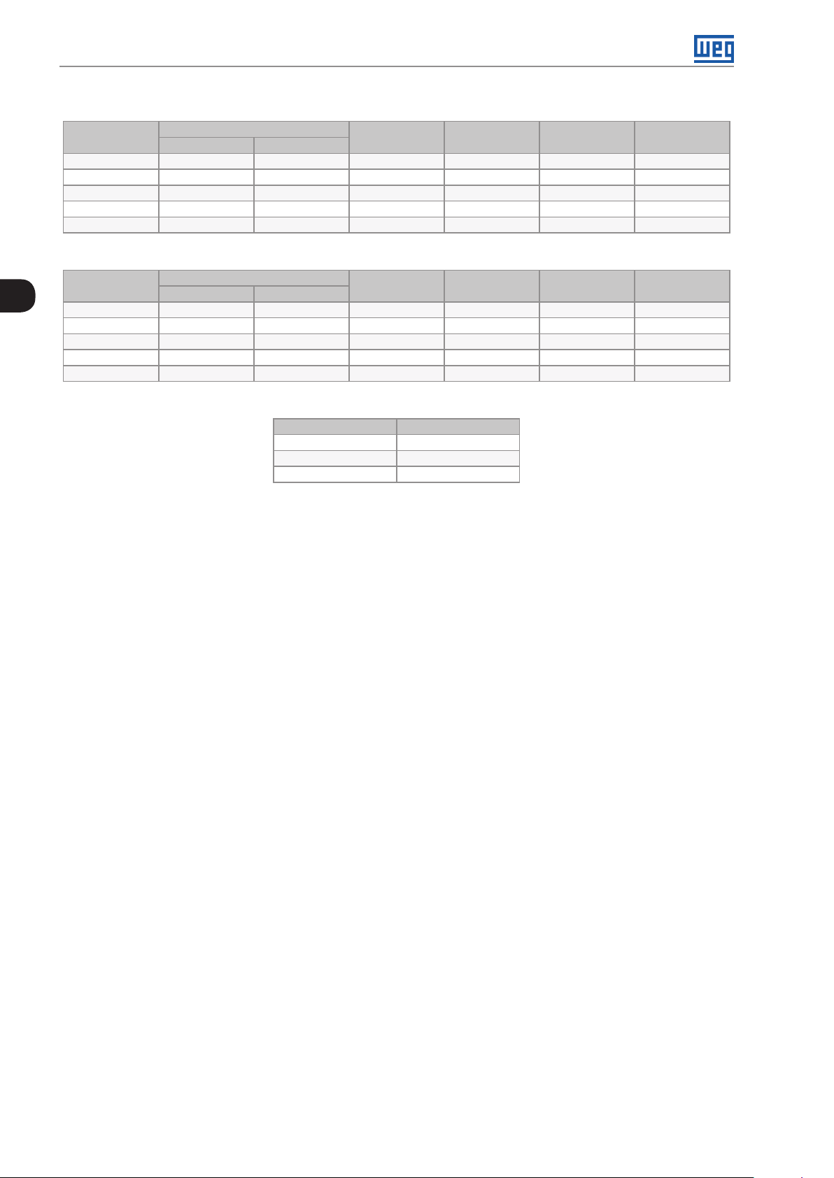
Use two parallel cables with the gauge indicated in Table 3.8 on page 3-16 to interconnect connections U, V and
W of the UP11 with the paralleling busbar (motor connection).
Table 3.9: Connection cables U, V and W
Minimum Cable
Current (A) Voltage (V) Duty
634
515 HD (2 X ) 185
496
380 HD (2X) 120
439
340 HD (2X) 120
380-480
500-600
660-690
ND (2X) 300
ND (2 X ) 185
ND (2X ) 150
Cross Section
(mm²)
ATTENTION!
Cables U, V and W of all phases of all paralleled UP11 must have the same length so as to prevent
current imbalance.
The characteristics of the cable used to connect the motor to the inverter, as well as its routing, are extremely
important to avoid electromagnetic interference in other equipment and not to affect the life cycle of windings and
bearings of the controlled motors.
Recommendations for motor cables:
Unshielded Cables:
They can be used when it is not necessary to comply with the European electromagnetic compatibility directive
(2014/30/EU).
Keep motor cables away from other cables (signal cables, sensor cables, control cables, etc.), according to
Table 3.9 on page 3-24.
The emission of the cables can be reduced by installing them within a metallic conduit, which must be grounded
at least at both ends.
Connect a fourth cable between the motor ground and the inverter ground.
3-24 | CFW-11M G2
Page 45
Installation and Connection
NOTE!
The magnetic field created by the current circulation in these cables may induce currents in nearby
metal parts, heating them, and cause additional electrical losses. Therefore, keep the three cables
(U, V, W) always together.
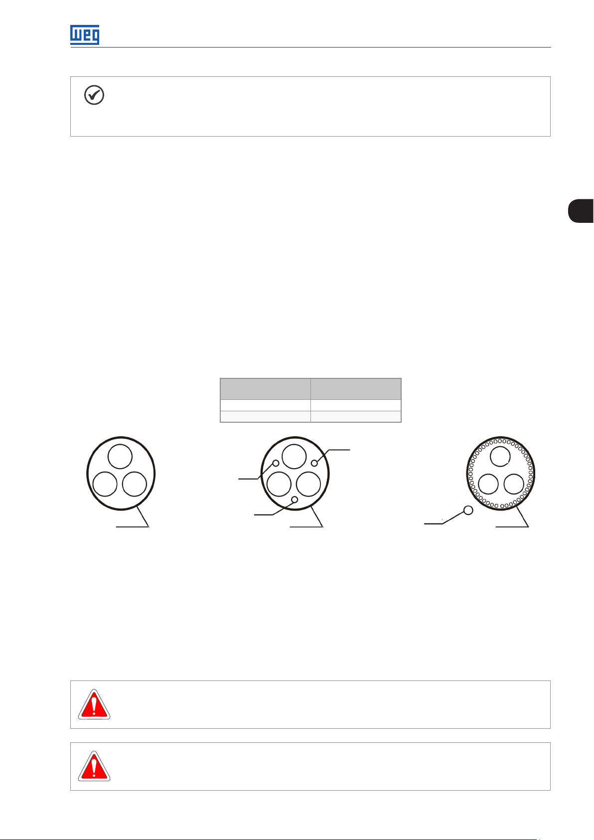
Shielded Cables:
They are mandatory when it is necessary to comply with the electromagnetic compatibility directive (89/336/
EEC), as defined by EN 61800-3 “Adjustable Speed Electrical Power Drive Systems”. It mainly acts reducing the
electromagnetic radiation disturbance produced by the motor cables in the radio frequency band.
Regarding the installation types and details, follow the recommendations of IEC 60034-25 “Guide For Design
and Performance of Cage Induction Motors Specifically Designed For Converter Supply”; see summary in Figure
3.29 on page 3-25. Refer to the standard for further details and occasional changes related to the new revisions.
Keep motor cables away from other cables (signal cables, sensor cables, control cables, etc.), according to
Table 3.10 on page 3-25.
The grounding system must be well interconnected among the several installation locations such as the grounding
points of the motor and the inverter. Voltage difference or impedance between the several points may cause the
circulation of parasite currents among the equipments connected to the ground, resulting in electromagnetic
interference problems.
3
Table 3.10: Minimum separation distance between motor cables and all other cables
Cable Length
≤ 30 m (100 ft) ≥ 10 cm (3.94 in)
> 30 m (100 ft) ≥ 25 cm (9.84 in)
U U U
PE
W W WV
PE
SCu SCu
Symmetrical shielded cables: three concentric conductors with or without a ground conductor, symmetrically manufactured, with an
external shield of copper or aluminum.
Note:
(1) SCu = copper or aluminum external shield.
(2) AFe = galvanized steel or iron.
(3) PE = ground conductor.
(4) Cable shielding must be grounded at both ends (inverter and motor). Use 360º connections for low impedance to high frequencies.
(5) For using the shield as a protective ground, it must have at least 50 % of the power cables conductivity. Otherwise, add an external ground conductor
and use the shield as an EMC protection.
(6) Shielding conductivity at high frequencies must be at least 10 % of the phase power cable conductivity.
Figure 3.29: Motor connection cables recommended by IEC 60034-25
Minimum Separation
Distance
PE
V V
PEs
AFe
3.2.8 Grounding Connections
DANGER!
Do not share the grounding wiring with other equipment that operate with high currents (e.g. high
power motors, soldering machines, etc.).
DANGER!
Ne pas partager le câblage de mise à la terre avec d’autres équipements opérant avec des intensités
élevées (par ex: moteurs haute puissance, postes de soudure, etc.).
CFW-11M G2 | 3-25
Page 46

Installation and Connection
ATTENTION!
The neutral conductor of the network must be solidly grounded; however, this conductor must not
be used to ground the inverter.
DANGER!
The inverter must be obligatorily connected to a protective ground (PE).
Observe the following:
Connect the grounding points of the inverter to a specific grounding rod, or specific grounding
point or to the general grounding point (resistance ≤ 10 Ω).
3
Use a minimum cable gauge for connection to the ground as indicated in Table 3.11 on page 3-26.
If local standards require different gauges, they must be observed.
For compatibility with IEC 61800-5-1 standard, use at least one copper cable of 10 mm
2
to connect
the inverter to the protective earth, since the leakage current is higher than 3.5 mA AC.
DANGER!
Le variateur doit être raccordé à une terre de protection (PE).
Observer les règles suivantes:
Connectez la masse du variateur à une barre collectrice de terre en un seul point ou à un point
commun de raccordement à la terre (impédance ≤ 10 Ω).
Utilisez la section minimale de raccordement à la terre indiquée dans les Table 3.11 on page 3-26.
Se conformer aux à la règlementation locale et/ou aux codes de l'électricité si une autre épaisseur
de fil est nécessaire.
Pour assurer la conformité avec la norme CEI 61800-5-1, connecter le variateur à la terre grâce à
un câble en cuivre à un conducteur ayant une épaisseur de fil minimale de 10 mm², étant donné
que le courant de fuite est supérieur à 3,5 mA C.A.
Use the cables with the gauge indicated in Table 3.11 on page 3-26 to ground the UP11 power units.
Table 3.11: Grounding cables
Current (A) Voltage (V) Duty
634
515 HD 185
496
380 HD 120
439
340 HD 120
380-480
500-600
660-690
ND 300
ND 185
ND 150
Minimum Cable
Cross Section (mm²)
3.2.9 IT Networks
NOTE!
The ground-fault protection (F074) is intended for IGBT protection and may not be activated when
inverter output is shorted to ground, when fed by IT networks.
External insulation monitoring devices should be used for system fault monitoring.
3-26 | CFW-11M G2
Page 47

3. 2 .10 Terminals Recommended for Power Cables
Installation and Connection
Cable Gauge
[mm2]
120
150
185
300
Wire Size
[AWG/ kcmil]
4/0
300
350
600
Screw Manufacturer Lug Terminal, Code Crimping Tool, Code
Hollingsworth RM120-12 Hydraulic tool H6-500
Tool without die: MY29-3 or Y644 or Y81
Tool+die: Y35 or Y750 / U29RT
Tool without die: Y644 or Y81
Tool+die: Y35 or Y750 / U30RT
Tool without die: Y644 or Y81
Tool+die: Y35 or Y750 / U31RT
Tool without die: Y644 or Y81
Tool+die: Y35 or Y750 / U36RT
Dieless tool: MY29-3 or Y644 or Y81
Tool+die: Y35 or Y750 / U29RT
Dieless tool: Y644 or Y81
Tool+die: Y35 or Y750 / U30RT
Dieless tool: Y644 or Y81
Tool+die: Y35 or Y750 / U31RT
Dieless tool: Y644 or Y81
Tool+die: Y35 or Y750 / U36RT
M12
Stud
Size
M12
Burndy (FCI) YA28L
Hollingsworth RM150-12 Hydraulic tool H6-500
Burndy (FCI) YA30L
Hollingsworth RM185-12 Hydraulic tool H6-500
Burndy (FCI) YA31L
Hollingsworth RM30 0 -12 Hydraulic tool H6-500
Burndy (FCI) YA36L 2
(a) Cables with size in mm2
Manufacturer Ring Lug, P/N Crimping Tool P/N
Hollingsworth R4012 Hydraulic Crimp Tool H6-500
Burndy (FCI) YA28L
Hollingsworth R 30012 Hydraulic Crimp Tool H6-500
Burndy (FCI) YA30L
Hollingsworth R 35012 Hydraulic Crimp Tool H6-500
Burndy (FCI) YA31L
Hollingsworth RM30 0 -12 Hydraulic Crimp Tool H6-500
Burndy (FCI) YA36L 2
Number of
Crimps
1
3
Number of
Crimps
1
(b) Cables with size in AWG
Table 3.12: (a) and (b) Recommended cable terminals for power connections
3. 2 .11 Dynamic Braking
The braking torque obtained by the application of frequency inverters without dynamic braking resistors varies
from 10 % to 35 % of the motor rated torque.
Braking resistors shall be used to obtain higher braking torques. In this case, the regenerated energy in excess is
dissipated in a resistor mounted outside the inverter.
This kind of braking is used in cases where short deceleration times are desired or when high-inertia loads are
driven.
The “Optimal Braking” feature may be used with the vector control mode, which eliminates in most cases the
need of an external braking resistor.
ATTENTION!
For the CFW-11M G2, use the DBW-04 braking module only. For further information, refer to the
manual of the accessory.
CFW-11M G2 | 3-27
Page 48

Installation and Connection
3. 2 .12 Control Connections
3. 2 .12 .1 UP11 G2 Connections
3
UP11 Control
Power Supply
Connectors
Fiber Optic
Connector DB25
Figure 3.30: Control cable connection points on the UP11 G2
3-28 | CFW-11M G2
Page 49

Installation and Connection
XC6: Power supply 24 Vdc
(UP11 G2 control)
Fiber optics connectors
(connections to the ICUP board)
XC40: Connector DB25
(connection to the ICUP board)
Figure 3.31: Identification of the control connections of the UP11 G2
The electronics of the UP11 G2 is powered via connector XC6, located on the IUP board; it is described in Figure
3.12 on page 3-9.
3
Table 3.13: Description of connector XC6
XC6 Function Specifications
1 +24 Vdc Positive pole of the +24 Vdc power supply
2 NC Not connected
3 GND 0 V reference for the +24 Vdc power supply
24 Vdc power supply (± 3 %)
Consumption: 750 mA per UP11 G2
CFW-11M G2 | 3-29
Page 50

Installation and Connection
3
Fan supply
terminals
Figure 3.32: Fan supply terminals
Table 3.14: Specification of the fan power supply of the fans
Volt ag e Frequency Current
220 Vac 50 / 60 Hz 4 Aca
3-30 | CFW-11M G2
Page 51

Installation and Connection
3.2.12.2 UC11 G2 Connections
DIM1 and DIM2 digital inputs located on the ICUP board (Table 3.13 on page 3-29) can be programmed via
parameters P0832 and P0833 respectively.
Table 3.15: Function of the signals on the connector XC5
Connector XC5 Factory Default Function Specifications
1 DIM1
2 DIM2
3 COM Common point of the digital inputs of the ICUP1 board
4 +24 V 24 Vdc power supply
5 GND_ 24 0 V reference for the 24 Vdc power supply
DIM1 isolated digital input, programmable in (P0832).
Refer to the programming manual
DIM2 isolated digital input, programmable in (P0833).
Refer to the programming manual
High level ≥ 18 V
Low level ≤ 3 V
Maximum input voltage: 30 V
Input current: 11 mA @ 24 Vdc
Isolated 24 Vdc ± 8 % power supply
Capacity: 600 mA
Note 1: This power supply may be used for feeding the ICUP
board digital inputs DIM1 (ISOL) and DIM2 (ISOL)
Note 2: This power supply is isolated from the 24 Vdc input
used to power ICUP
Note 3: This is the same power supply available on the CC11
board
Fiber optics
connectors
(connection to UP11)
3
XC60: Connection
to Control Rack
XC67: Connection
to the Control Rack
(safety stop)
DIP
switches
S1 and S2
Figure 3.33: ICUP board connection points
Fiber optics
connectors reserved
for WEG use
Connectors DB25
XC40A to XC40E
(connection to UP11)
XC5: DIM1 and DIM2
Digital Inputs
XC9: 24 Vdc Power
Supply Input
The control rack is powered via connector XC9, located on the ICUP board; it is described in Table 3.14 on page
3-30.
Table 3.16: Description of connector XC9
XC9 Function Specifications
1 +24 Vdc Positive pole of the +24 Vdc power supply
2 NC Not connected
3 GND 0 V reference for the +24 Vdc power supply
24 Vdc power supply (± 3 %)
Consumption: 1.25 A
DIP switches S1 and S2, Figure 3.34 on page 3-32, have the function, respectively, to select the level of the
inverter alternate supply voltage and the number of UP11 connected.
CFW-11M G2 | 3-31
Page 52

Installation and Connection
S2S1
3
Figure 3.34: DIP switches S1 and S2 detail
Table 3.17: DIP switch S1:1 - S1:3 configuration
S1:3 S1:2 S1:1
ON OFF ON 380 - 480 V
ON OFF OFF 500 - 690 V
Table 3.18: DIP switch S1:4 configuration
S1:4 Operating Mode
OFF Normal
ON Reduced Power
The operating mode with reduced power is detailed in Section 5.7 OPERATION WITH A REDUCED NUMBER OF
POWER UNITS on page 5-10.
Table 3.19: DIP switch S2 configuration
S2:4 S2:3 S2:2 S2:1
OFF OFF OFF OFF 1
OFF OFF OFF ON 2
OFF OFF ON ON 3
OFF ON ON ON 4
ON ON ON ON 5
Alternate Supply
Volt ag e
Number
of UP11
Connected
The grounding of the UP11 plus UC11 must be done according to the diagram shown in Figure 3.35 on page 3-33.
3-32 | CFW-11M G2
Page 53

ICUP
Installation and Connection
-UD
+UD
3
+UD
XC6
-UD
XC40
U
UH...WL
XC33
112
220 V
V
1
W
ac
Motor
220 Vac
24 Vdc power
supply
Safety
Digital
Dynamic
1
3
stop
inputs
BR
Error_BR
braking
XC40B XC40A
XC9XC67XC5
XC40D XC40C
3
ICUP shield
fixing screw
CX60
CX60
XC 98 CV11
CC 11
CC11 rack
grounding
UH5...WL5 XC40E UH4...WL4 U H3...WL3 UH2...WL2 UH1...WL1
Rack C C11
Panel grounding busbar
Figure 3.35: Grounding diagram of the UP11 plus UC11, in case of only one UP11
The screws to fasten the ICUP shield to the panel must ensure the electrical contact between the shield and the
panel for grounding.
CFW-11M G2 | 3-33
Page 54

Installation and Connection
3
Figure 3.36: ICUP shield fastened to the panel
The control rack must be grounded using a flat flexible braid with minimum width of 5 mm and minimum cross
section of 3 mm² with standard FASTON terminal 6.35 mm (E.g.: TYCO 735075-0 and 180363-2) and lug terminal
M4; see Figure 3.37 on page 3-34.
Figure 3.37: Control rack grounding
The panel door must be grounded with a braided ground strap.
Figure 3.38: Panel door grounding
Flexible braid
3-34 | CFW-11M G2
Page 55

Installation and Connection
3.2.12.3 CC11 Connections
The control connections (analog inputs/outputs, digital inputs/outputs), must be made at the CC11 control board
terminal strip XC1.
Functions and typical connections are presented in Figure 3.39 on page 3-35 and Figure 3.40 on page 3-36.
XC1
CW
≥5 kΩ
CCW
rpm
amp
Terminal
Strip
1 REF+
2 A I1+ Analog input # 1:
3 AI1-
4 REF-
5 AI2+ Analog input # 2:
6 AI2-
7 AO1
AGND
8
(24 V )
9 AO2
AGND
10
(24 V )
11 DGND*
12 COM
13 24 Vdc
14 COM
15 DI1
16 DI2
17 DI3
18 DI4
19 DI5
20 DI6
21 NF1 Digital output #1 DO1 (RL1):
22 C1
23 N A1
24 NF2 Digital output #2 DO2 (RL2):
25 C2
26 NA2
27 NF3 Digital output #3 DO3 (RL3):
28 C3
29 NA3
Factory Setting Function Specifications
Positive reference for
potentiometer
speed reference (remote)
Negative reference for
potentiometer
no function
Analog output # 1:
speed
Reference (0 V) for the
analog outputs
Analog output # 2:
motor current
Reference (0 V) for the
analog outputs
Reference (0 V) for the 24
Vdc power supply
Common point of the digital
inputs
24 Vdc power supply 24 Vdc power supply, ±8 %
Common point of the digital
inputs
Digital input # 1:
Start/Stop
Digital input # 2:
direction of rotation (remote)
Digital input # 3:
no function
Digital input # 4:
no function
Digital input # 5:
Jog (remote)
Digital input # 6:
2nd ramp
no fault
N > NX - speed>P0288
N* > NX - speed reference
> P0288
Output voltage: +5.4 V, ±5 %
Maximum output current: 2 mA
Differential
Resolution: 12 bits
Signal: 0 to 10 V (RIN = 400 kΩ) / 0 to 20 mA / 4 to 20 mA (RIN = 500 Ω)
Maximum voltage: ±30 V
Output voltage: -4.7 V, ±5 %
Maximum output current: 2 mA
Differential
Resolution: 11 bits + signal
Signal: 0 to ±10 V (RIN = 400 kΩ) / 0 to 20 mA / 4 to 20 mA (RIN = 500 Ω)
Maximum voltage: ±30 V
Galvanic isolation
Resolution: 11 bits
Signal: 0 to 10 V (RL ≥ 10 kΩ) / 0 to 20 mA / 4 to 20 mA (RL ≤ 500 Ω)
Protected against short-circuit
Connected to the ground (frame) through an impedance: 940 Ω
resistor in parallel with a 22 nF capacitor. Same reference as the one
of DGND *
Galvanic isolation
Resolution: 11 bits
Signal: 0 to 10 V (RL ≥ 10 kΩ) / 0 to 20 mA / 4 to 20 mA (RL ≤ 500 Ω)
Protected against short-circuit
Connected to the ground (frame) through an impedance: 940 Ω
resistor in parallel with a 22 nF capacitor. Same reference as the one
of DGND *
Connected to the ground (frame) through an impedance: 940 Ω
resistor in parallel with a 22 nF capacitor. Same reference as the one
of AGND (24 V)
Capacity: 500 mA
6 isolated digital inputs
High level ≥ 18 V
Low level ≤ 3 V
Input voltage ≤ 30 V
Input current: 11 mA @ 24 Vdc
Contact rating:
Maximum voltage: 240 Vac
Maximum current: 1 A
NC - normally closed contact
C - common
NO - normally open contact
3
Figure 3.39: Signals of connector XC1 - Digital inputs as active high
CFW-11M G2 | 3-35
Page 56

Installation and Connection
XC1
Terminal
Strip
CW
≥5 kΩ
CCW
3
rpm
amp
1 REF+
2 AI1+ Analog input # 1:
3 AI1-
4 REF-
5 A I2+ Analog input # 2:
6 AI2-
7 AO1
AGND
8
(24 V )
9 AO2
AGND
10
(24 V )
11 DGND*
12 COM
13 24 Vdc
14 COM
15 DI1
16 DI2
17 DI3
18 DI4
19 DI5
20 DI6
21 NF1 Digital output #1 DO1 (RL1):
22 C1
23 NA1
24 NF2 Digital output #2 DO2 (RL2):
25 C2
26 NA2
27 NF3 Digital output #3 DO3 (RL3):
28 C3
29 NA3
Factory Setting Function Specifications
Positive reference for
potentiometer
speed reference (remote)
Negative reference for
potentiometer
no function
Analog output # 1:
speed
Reference (0 V) for the
analog outputs
Analog output # 2:
motor current
Reference (0 V) for the
analog outputs
Reference (0 V) for the 24
Vdc power supply
Common point of the digital
inputs
24 Vdc power supply 24 Vdc power supply, ±8 %
Common point of the digital
inputs
Digital input # 1:
Start/Stop
Digital input # 2:
direction of rotation (remote)
Digital input # 3:
no function
Digital input # 4:
no function
Digital input # 5:
Jog (remote)
Digital input # 6:
2nd ramp
no fault
N > NX - speed>P0288
N* > NX - speed reference
> P0288
Output voltage: +5.4 V, ±5 %
Maximum output current: 2 mA
Differential
Resolution: 12 bits
Signal: 0 to 10 V (RIN = 400 kΩ) / 0 to 20 mA / 4 to 20 mA (RIN = 500 Ω)
Maximum voltage: ±30 V
Output voltage: -4.7 V, ±5 %
Maximum output current: 2 mA
Differential
Resolution: 11 bits + signal
Signal: 0 to ±10 V (RIN = 400 kΩ) / 0 to 20 mA / 4 to 20 mA (RIN = 500 Ω)
Maximum voltage: ±30 V
Galvanic isolation
Resolution: 11 bits
Signal: 0 to 10 V (RL ≥ 10 kΩ) / 0 to 20 mA / 4 to 20 mA (RL ≤ 500 Ω)
Protected against short-circuit
Connected to the ground (frame) through an impedance: 940 Ω
resistor in parallel with a 22 nF capacitor. Same reference as the one
of DGND *
Galvanic isolation
Resolution: 11 bits.
Signal: 0 to 10 V (RL ≥ 10 kΩ) / 0 to 20 mA / 4 to 20 mA (RL ≤ 500 Ω).
Protected against short-circuit.
Connected to the ground (frame) through an impedance: 940 Ω
resistor in parallel with a 22 nF capacitor. Same reference as the one
of DGND *
Connected to the ground (frame) through an impedance: 940 Ω
resistor in parallel with a 22 nF capacitor. Same reference as the one
of AGND (24 V)
Capacity: 500 mA
6 isolated digital inputs
High level ≥ 18 V
Low level ≤ 3 V
Input voltage ≤ 30 V
Input current: 11 mA @ 24 Vdc
Contact rating:
Maximum voltage: 240 Vac
Maximum current: 1 A
NC - normally closed contact
C - common
NO - normally open contact
NOTE!
In order to use the digital inputs as active low, it is necessary to remove the jumper between XC1: 11
and 12 and change it to XC1:12 and 13.
3-36 | CFW-11M G2
Figure 3.40: Signals of connector XC1 - Digital inputs as active low
Page 57

Installation and Connection
Slot 5
1
Slot 1 (white)
3
XC1
29
Figure 3.41: Connector XC1 and switches to select the signal type of the analog inputs and outputs
Slot 2 (yellow)
Slot 3 (green)
Slot 4
As the factory setting, the analog inputs and outputs are adjusted to operate in the 0 to 10 V range, but they can
be changed by using the S1 DIP-switch.
Table 3.20: Configurations of the switches to select the signal type of the analog inputs and outputs
Signal Factory Setting Function DIP-Switch Selection
AI1 Speed Reference (remote) S1.4
AI2 No function S1.3
AO1 Speed S1.1
AO2 Motor Current S1.2
OFF: 0 to 10 V (factory setting)
ON: 4 to 20 mA / 0 to 20 mA
OFF: 0 to ±10 V (factory setting)
ON: 4 to 20 mA / 0 to 20 mA
OFF: 4 to 20 mA / 0 to 20 mA
ON: 0 to 10 V (factory setting)
OFF: 4 to 20 mA / 0 to 20 mA
ON: 0 to 10 V (factory setting)
Factory
Setting
OFF
OFF
ON
ON
Parameters related to the analog inputs and outputs (AI1, AI2, AO1, and AO2) must be programmed according to
the DIP-switches settings and desired values.
Follow instructions below for the proper installation of the control wiring:
1. Wire gauge: 0.5 mm² (20 AWG) to 1.5 mm² (14 AWG).
2. Maximum tightening torque: 0.5 N.m (4.50 lbf.in).
3. Use shielded cables for the connections at XC1 and run the cables separated from the remaining circuits
(power, 110 V/220 Vac control, etc.), as presented in Table 3.20 on page 3-37. If control cables must cross
other cables, it must be done perpendicularly among them, keeping a minimum of 5 cm (1.9 in) distance at
the crossing point.
Table 3.21: Minimum separation distances between wiring
Wiring Length
≤ 30 m (100 ft) ≥ 10 cm (3.94 in)
> 30 m (100 ft) ≥ 25 cm (9.84 in)
Minimum Separation
Distance
CFW-11M G2 | 3-37
Page 58

Installation and Connection
The correct connection of the cable shield is shown in Figure 3.43 on page 3-38.
Insulate with tape
Inverter
Side
3
Do not ground
Figure 3.42: Conexão da blindagem
Figure 3.43: Example of shield connection for the control wiring
4. Relays, contactors, solenoids or coils of electromechanical brakes installed close to the inverter may eventually
create interferences in the control circuit. To eliminate this effect, RC suppressors (with AC power supply) or
free-wheel diodes (with DC power supply) shall be connected in parallel to the coils of these devices.
3-38 | CFW-11M G2
Page 59

Installation and Connection
LOC
REM
LOC
REM
3.2.12.4 Typical Control Connections
Control connection 1 - Run/Stop function controlled from the keypad (Local Mode).
With this control connection it is possible to run the inverter in local mode with the factory default settings. This
operation mode is recommended for first-time users, since no additional control connections are required.
For the start-up in this operation mode, please follow instructions listed in Chapter 5 FIRST TIME POWER-UP
AND START-UP on page 5-1.
Control connection 2 - Wire Run/Stop function (Remote Mode).
This wiring example is valid only for the default factory settings and if the inverter is set to remote mode.
With the factory default settings, the selection of the operation mode (local/remote) is performed through the HMI key
to remote mode (local mode is default).
3
Set P0220 = 3 to change the default setting of operator key
H
≥5 kΩ
AH
Run/Stop
Forward/Reverse (FWD/REV)
Jog
to remote mode.
XC1 Terminal Strip
1 + REF
2 A I1+
3 AI14 - REF
5 AI2+
6 AI27 AO1
8 AGND (24 V)
9 AO2
10 AGND (24 V)
11 DGND
12 COM
13 24 Vdc
14 COM
15 DI1
16 DI2
17 DI3
18 DI4
19 DI5
20 DI6
21 NF1
22 C1
23 NA1
24 NF2
25 C2
26 NA2
27 NF3
28 C3
29 NA3
*
DO1
(RL1)
DO2
(RL2)
DO3
(RL3)
Figure 3.44: XC1 wiring for Control Connection #2
CFW-11M G2 | 3-39
Page 60

Installation and Connection
Control connection 3 - Wire Run/Stop function.
Enabling the Run/Stop function with 3-wire control.
Parameters to be set:
Set DI3 to START.
P0265 = 6.
Set DI4 to STOP.
3
P0266 = 7.
Set P0224 = 1 (DIx) for 3-wire control in Local mode.
Set P0227 = 1 (DIx) for 3-wire control in Remote mode.
Set the Forward/Reverse selection by using digital input # 2 (DI2).
Set P0223 = 4 for Local Mode or P0226 = 4 for Remote Mode.
S1 and S2 are Start (NO contact) and Stop (NC contact) pushbuttons respectively.
The speed reference can be provided through the analog input (as in control connection # 2), through the keypad
(as in control connection # 1) or through other available source.
XC1 Terminal Strip
1 + REF
2 A I1+
3 AI14 - REF
5 AI2+
6 AI27 AO1
8 AGND (24 V)
9 AO2
10 AGND (24 V)
Forward/Reverse S3
(FWD/REV)
Start S1
Stop S2
11 DGND
12 COM
13 24 Vdc
14 COM
15 DI1
16 DI2
17 DI3
18 DI4
19 DI5
20 DI6
21 NF1
22 C1
23 NA1
24 NF2
25 C2
26 NA2
27 NF3
28 C3
29 NA3
*
DO1
(RL1)
DO2
(RL2)
DO3
(RL3)
3-40 | CFW-11M G2
Figure 3.45: XC1 wiring for control connection # 3
Page 61
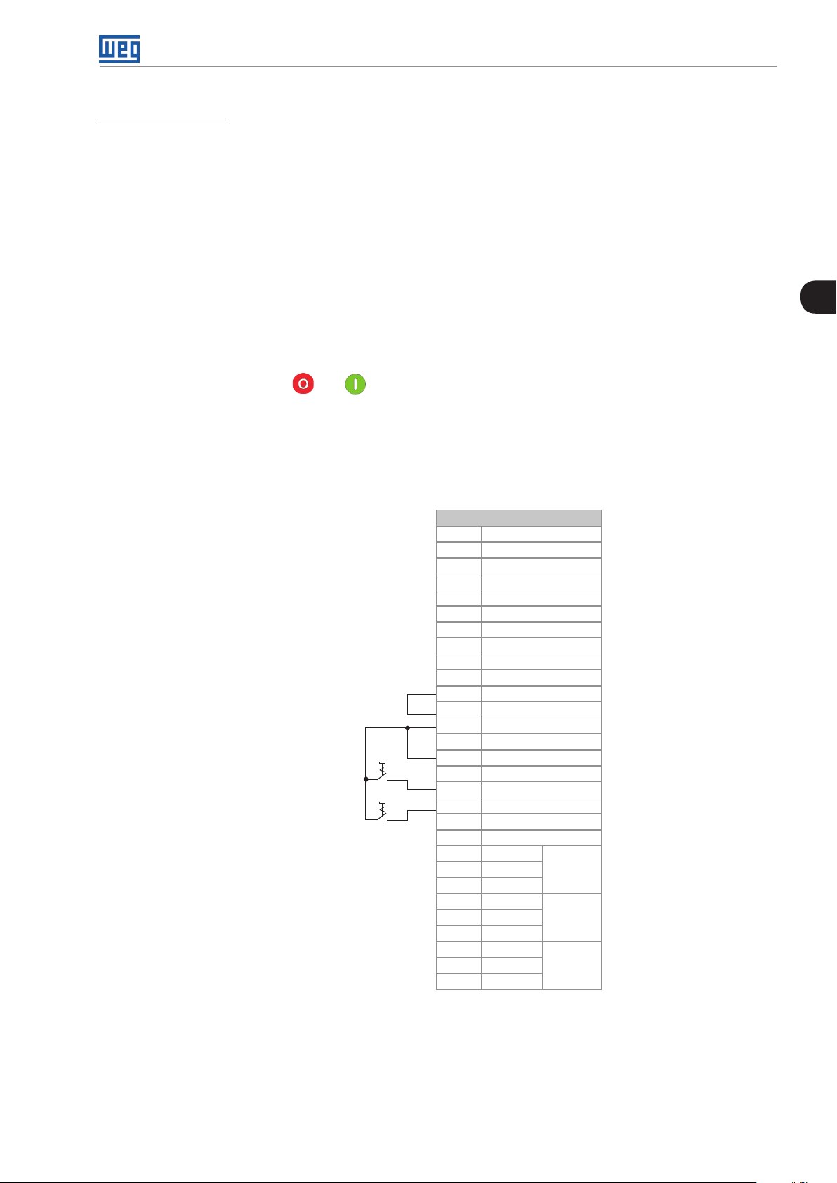
Installation and Connection
Control connection 4 - Forward/Reverse.
Enabling the Forward/Reverse function.
Parameters to be set:
Set DI3 to Forward run.
P0265 = 4.
Set DI4 to Reverse run.
P0266 = 5.
When the Forward/Reverse function is set, it will be active either in Local or Remote mode.
At the same time, the HMI keys and will remain always inactive (even if P0224 = 0 or P0227 = 0).
The direction of rotation is determined by the Forward run and Reverse run inputs.
Clockwise direction for Forward run and counterclockwise for Reverse run.
3
The speed reference can be provided by any source (as in the control connection # 3).
XC1 Terminal Strip
1 + REF
2 A I1+
3 AI14 - REF
5 AI2+
6 AI27 AO1
8 AGND (24 V)
9 AO2
10 AGND (24 V)
Strop/Forward S1
Strop/Reverse S2
11 DGND
12 COM
13 24 Vdc
14 COM
15 DI1
16 DI2
17 DI3
18 DI4
19 DI5
20 DI6
21 NF1
22 C1
23 NA1
24 NF2
25 C2
26 NA2
27 NF3
28 C3
29 NA3
*
DO1
(RL1)
DO2
(RL2)
DO3
(RL3)
Figure 3.46: XC1 wiring for control connection # 4
CFW-11M G2 | 3-41
Page 62

Installation and Connection
3.3 SAFETY STOP FUNCTION
The CFW11MG2...O...Y... inverters have the SRB board that provides the Safety Stop function. Through this board
it is possible to control two safety relays (K1 and K2) which act directly on the power circuit, more specifically on
the power supply of the IGBT activation fiber optics. The safety relays ensure that the IGBTs remain turned off
when the Safety Stop function is activated, even in case of only one internal fault. The position of the SRB boards
and terminals XC25 (Safety Stop control terminals) on the inverter is shown in Figure 3.47 on page 3-42.
The Safety Stop function prevents the accidental start of the motor.
3
SRB Board
XC25
DANGER!
The activation of the Safety Stop function does not ensure the electrical safety of the motor terminals
(which are not isolated from the power supply in such condition).
DANGER!
L'activation de la fonction d'arrêt de sécurité ne garantit pas la sécurité électrique des bornes du
moteur (elles ne sont pas isolées de l'alimentation électrique dans cet état).
ATTENTION!
In case of a multiple fault in the power stage of the inverter, the motor shaft can rotate up to 360/
(number of poles) degrees even with the activation of Safety Stop function. That must be considered
in the application.
3-42 | CFW-11M G2
Figure 3.47: Location of the SRB board on the control rack
Page 63

Installation and Connection
NOTE!
Inverter Safety Stop function is only one component of the safety control system of a machine
and/or process. When inverter and its Safety Stop function is correctly used and with other safety
components, it’s possible to fulfill the requirements of standard EN 954-1 / ISO 13849-1, Category 3
(machine safety) and IEC/EN 61508, SIL2 (safety control/signaling applied to processes and systems).
Parameter P0029 indicates if the inverter identified the SRB board correctly. See Bit 9 in Table 3.20 on page 3-37
for further details.
Table 3.22: Content of parameter P0029
Bits
15 14 13 12 11 10 9 8 7 6 5 4 3 2 1 0
0 = inverter without safety
1 1 0 0 0 1
Hexadecimal digit #4 Hexadecimal digit #3 Hexadecimal digit #2 Hexadecimal digit #1
stop option
1 = inverter with safety
stop option
Inverter voltage:
01 = 380..480 V
0
10 = 500..600 V
11 = 500..690 V
or 660/690 V
Rated output current of the inverter
3.3.1 Installation
NOTE!
The inverter must be installed inside an IP54 (minimum) cabinet.
Table 3.23: XC25 terminals (Safety Stop terminals) signals
Connector XC25 Function Specifications
1 STO1 Terminal 1 of safety relay K1 coil
2 GND1 Terminal 2 of safety relay K1 coil
3 STO2 Terminal 1 of safety relay K2 coil
4 GND2 Terminal 2 of safety relay K2 coil
NOTE!
Follow the recommendations of Item 3.2.12 Control Connections on page 3-28.
Coil rated voltage: 24 V, range: 20…30 Vdc
Coil resistance: 960 Ω ± 10 % @ 20 °C (68 ºF)
Coil rated voltage: 24 V, range: 20…30 Vdc
Coil resistance: 960 Ω ± 10 % @ 20 °C (68 ºF)
3
For XC25 control cabling considers the following:
Use wire gauge from 0.5 mm
2
(20 AWG) to 1.5 mm2 (14 AWG) and maximum tightening torque of maximum
0.50 N.m (4.50 lbf.in).
Use shielded cables connected to ground only on inverter side. Use the provided metallic pieces as shown on
Figure 3.48 on page 3-45.
Run the cables separated from the remaining circuits (power, 110 V / 220 Vac control, etc.).
CFW-11M G2 | 3-43
Page 64

Installation and Connection
3.3.2 Operation
3.3.2.1 Truth Table
Table 3.24: Safety Stop function operation
STO1 Logic Level
(voltage between
XC25:1-2 terminals)
0 (0 V) 0 (0 V)
3
0 (0 V) 1 (24 V)
1 (24 V) 0 (0 V)
1 (24 V) 1 (24 V) Disabled Inverter accepts commands normally
NOTE!
Maximum delay between signals STO1 and STO2: 100 ms (otherwise, fault F160 will occur).
The Safety Stop function has priority over the other functions of the inverter.
STO2 Logic Level
(voltage between
XC25:3-4 terminals)
Safety Stop
Function
Active
(enabled)
Fault
Inverter Behavior
Inverter remains in STO state and does not accept
commands. In order to escape this condition,
it’s required to have STO1 = 1 and STO2 = 1
simultaneously
Inverter is tripped by F160 fault (Safety Stop
function related fault). To escape this condition,
it’s required to reset the inverter
This function must not be used as control to start and/stop the inverter.
3.3.2.2 Inverter State, Fault and Alarm
Table 3.25: State of inverter, fault and alarm related to Safety Stop function
State/Fault/Alarm Description Cause
STO State Safety Stop activated
F160 fault Safety Stop function fault
Voltage between terminals 1 and 2 (relay K1 coil) and between terminals 3 and 4 (relay
K2 coil) of XC25 lower than 17 V
It’s applied voltage to relay K1 coil (STO1) but it’s not applied voltage to relay K2 coil
(STO2) or vice-versa or there is a delay of more than 100 ms between one signal and
the other. To solve it, correct the external circuit that generates STO1 and STO2 signals
3.3.2.3 Indication of STO Status
State of the inverter is shown on the left upper side of the display and in parameter P0006.
Possible states of the inverter: ready, run (inverter enabled), undervoltage, fault, self-tuning, configuration, DC
braking and STO (Safety Stop function activated).
It’s possible to set one or more digital and relay outputs of the inverter to indicate that Safety Stop function is
activated (state of the inverter = STO), if the inverter is or not on a fault state and more specifically if the inverter
was tripped by F160 fault (Safety Stop function fault). For that use the parameters P0275 (DO1), P0276 (DO2),
P0277 (DO3), P0278 (DO4) and P0279 (DO5) according to Table 3.25 on page 3-44.
Table 3.26: P0275...P0279 options for indication of state of inverter or faults on DOx digital outputs
DOx Digital Output function
Inverter status = STO
(Safety Stop function enabled)
Faul t F160
(inverter tripped by actuation of fault of the Safety
Stop function)
Fault
(inverter tripped by the actuation of any fault)
Without fault
(inverter status is not fault)
Value to be Set in
P0275...P0279
33 Safety Stop function disabled:
relay/transistor OFF
Safety Stop function enabled:
relay/transistor ON
34 Without fault F160: relay/transistor OFF
With fault F160: relay/transistor ON
13 Without fault: relay/transistor OFF
With fault: relay/transistor ON
26 With fault: relay/transistor OFF
Without fault: relay/transistor ON
Comment
Refer to inverter programming manual for a complete list of options for parameters P0275...P0279.
3-44 | CFW-11M G2
Page 65

Installation and Connection
3.3.2.4 Periodical Test
Safety Stop function, alternatively safety stop inputs (STO1 and STO2), must be activated at least once a year for
preventive maintenance purposes. Inverter power supply must be switched off and then on again before carrying
out this preventive maintenance. If during testing the power supply to the motor is not switched off, safety integrity
is no longer assured for the Safety Stop function. The drive must therefore be replaced to ensure the operational
safety of the machine or of the system process.
3.3.2.5 Examples of Wiring Diagrams of the Inverter Control Signal
It is recommended to use inverter DI1 and DI2 digital inputs set as 3-wire start/stop commands and the wiring
diagrams of inverter control signal according to Figure 3.48 on page 3-45.
XC1:1 - DGND*
XC1:12 - COM
XC25:2 - GND (R1-)
XC25:4 - GND (R2-)
XC1:13 - +24 V
Start
XC1:15 - DI1
Stop
XC1:16 - DI2
XC25:1 - STO1 (R1+)
XC25:3 - STO2 (R2+)
Safety relay
CF W -11
3
(a) STO or SS0 safety function (without an external safety relay)
XC1:11 - DGND*
XC1:12 - COM
XC25:2 - GND (R1-)
XC25:4 - GND (R2-)
XC1:13 - +24 V
13 23 47 57
External
safety relay
XC1:15 - DI1
XC1:16 - DI2
XC25:1 - STO1 (R1+)
XC25:3 - STO2 (R2+)
CF W -11
Note:
(*) For specifications of external safety relay, which is required to realize SS1 (stop category 1), refer to Item 3.3.3 Technical Specifications on page 3-46.
Figure 3.48: (a) and (b) Inverter control wiring examples (XC1 and XC25 terminals) to realize STO (or SS0, i.e., stop category 0) and SS1
(stop category 1) safety functions according to IEC/EN 61800-5-2 and IEC/EN 60204-1 standards - DI1 and DI2 inputs set as 3-wire start/
Start
Stop
(b) SS1 safety function with an external safety relay
stop commands
14 24 48 58
(*)
A1 A 2
CFW-11M G2 | 3-45
Page 66

Installation and Connection
Circuit operation of SS1 function from Figure 3.48 on page 3-45:
In this case, when the activation command is given to the external safety relay, safety relay opens inverter DI2
signal (via terminals 23 to 24) and motor is decelerated first by the inverter (via deceleration ramp). When the time
delay set at the external safety relay expires (this delay must be higher than required time to stop the motor, taking
into account deceleration time set on the inverter and inertia of the motor load), the safety relay delayed contacts
(terminals 47 to 48 and 57 to 58) opens inverter STO1 and STO2 signals and the inverter Safety Stop function is
activated. The motor stops according to category 1 (SS1) of standard IEC/EN 60204-1.
In order to drive the motor again, it is required to apply STO1 and STO2 signals again (to close terminals 13 to 23
and 23 to 24) and apply a pulse on inverter DI1 input (START).
3
3.3.3 Technical Specifications
3.3.3.1 Electrical Control Characteristic
Table 3.27: Electrical control characteristic
Inputs of the Safety Stop function XC25:1-2, XC25:3-4 2 independent inputs for the Safety Stop function
External safety relay specifications (only
when SS1 function is required according
to IEC/EN 61800-5-2 and IEC/EN 602041 standards) refer to Figure 3.48 on page
3-45
General requirements IEC 61508 and/or EN 954-1 and/or ISO 13849-1
Output requirements Number of current paths: 2 independent paths (one for each STO path)
Example Type/manufacturer: WEG/ Instrutech CPt-D
Power Supply: 24 Vdc (max. 30 V)
Impedance: 960 Ω
Status 0 if < 2 V, status 1 if > 17 V
Switching voltage capacity: 30 Vdc per contact
Switching current capacity: 100 mA per contact
Maximum switching delay between contacts: 100 ms
3.3.3.2 Operating Safety Characteristic
Table 3.28: Operating safety characteristic
Protection
Of the
machine
Of the system
process
Safety Stop function which forces stopping and/or prevents the motor from restarting unintentionally,
conforming to EN 954-1 / ISO 13849-1 category 3, IEC/EN 61800-5-2 and IEC/EN 60204-1
Safety Stop function which forces stopping and/or prevents the motor from restarting unintentionally,
conforming to IEC/EN 61508 level SIL2 and IEC/EN 61800-5-2
3.4 INSTALLATIONS ACCORDING TO THE EUROPEAN ELECTROMAGNETIC COMPATIBILITY DIRECTIVE
The CFW-11M G2 inverters, when correctly installed, meet the requirements of the EMC Directive 2004/108/EC.
The CFW-11M G2 inverter series has been designed only for industrial applications. Therefore, the emission limits
of harmonic currents defined by the standards EN 61000-3-2 and EN 61000-3-2/A14 are not applicable.
3. 4.1 Conformal Installation
For conformal installation use:
Standard CFW-11M G2 inverter for emission levels according to IEC/EN61800-3 “Adjustable Speed Electrical
Power Drive Systems”, category C4.
Shielded output cables (motor cables) with the shield connected at both ends, motor and inverter, with low-
impedance connection for high frequency. Keep the separation from the other cables according to Table 3.20
on page 3-37.
If you wish Category C3 conducted emission level, use external RFI filter on the inverter input. For more information
(RFI filter code, motor cable length and emission levels) refer to Table 3.28 on page 3-46.
Shielded control cables, keeping the separation distance from other cables according to Item 3.2.12.3 CC11
Connections on page 3-35.
3-46 | CFW-11M G2
Page 67

Installation and Connection
Grounding of the inverter according to instructions of Item 3.2.8 Grounding Connections on page 3-25.
3.4.2 Definition of the Standards
IEC/EN 61800-3: “Adjustable Speed Electrical Power Drives Systems”.
Environments:
First Environment: includes domestic premises. It also includes establishments directly connected without
intermediate transformer to a low-voltage power supply network which supplies buildings used for domestic
purposes.
Example: houses, apartments, commercial installations, or offices located in residential buildings.
Second Environment: includes all establishments other than those directly connected to a low-voltage power
supply network which supplies buildings used for domestic purposes.
Example: industrial area, technical area of any building supplied by a dedicated transformer.
Categories:
3
Category C1: inverters with a voltage rating less than 1000 V and intended for use in the First Environment.
Category C2: inverters with a voltage rating less than 1000 V, intended for use in the First Environment, not
provided with a plug connector or a movable installations, and installed and commissioned by a professional.
Note: a professional is a person or organization familiar with the installation and/or commissioning of inverters,
including the EMC aspects.
Category C3: inverters with a voltage rating less than 1000 V and intended for use in the Second Environment
only (not designed for use in the First Environment).
Category C4: inverters with a voltage rating equal to or greater than 1000 V, or with a current rating equal to or
greater than 400 Amps, or intended for use in complex systems in the Second Environment.
EN 55011: “Threshold values and measuring methods for radio interference from industrial, scientific and medical
(ISM) high-frequency equipment”.
Class B: equipment intended for use in the low-voltage power supply network (residential, commercial, and lightindustrial environments).
Class A1: equipment intended for use in the low-voltage power supply network. Restricted distribution.
Note: must be installed and commissioned by a professional when applied in the low-voltage power supply network.
Class A2: equipment intended for use in industrial environments.
CFW-11M G2 | 3-47
Page 68

Installation and Connection
3.4.3 Emission and Immunity Levels Met
Table 3.29: Emission and immunity levels met
EMC Phenomenon Basic Standard Level
Emission
Mains Terminal Disturbance Voltage
Frequency Range: 150 kHz to 30 MHz
Electromagnetic Radiation Disturbance
Frequency Range: 30 kHz to 1 GHz
Immunity:
Electrostatic Discharge (ESD) IEC/EN61000-4-2 4 kV for contact discharge and 8 kV for air discharge
Fast Transient-Burst IEC/EN61000-4-4 2 kV / 5 kHz (coupling capacitor) power input cables
3
Conducted Radio-Frequency Common Mode IEC/EN61000-4-6 0.15 to 80 MHz; 10 V; 80 % AM (1 kHz)
Surges IEC/EN61000-4-5 1.2/50 µs, 8/20 µs
Radio-Frequency Electromagnetic Field IEC/EN61000-4-3 80 to 1000 MHz
IEC/EN61800-3 It depends on the inverter model and on the motor
cable lenght. Refer to Table 3.28 on page 3-46
1 kV / 5 kHz control cables, and remote keypad cables
2 kV / 5 kHz (coupling capacitor) motor output cables
Motor cables, control cables, and remote keypad
cables
1 kV line-to-line coupling
2 kV line-to-ground coupling
10 V/m
80 % AM (1 kHz)
Table 3.30: Filters to meet the emission levels category C3
Inverter Model
CFW11M 0634 T 4 TBD TBD TBD
CFW11M 1205 T 4 TBD TBD TBD
CFW11M 1807 T 4 TBD TBD TBD
CFW11M 2409 T 4 TBD TBD TBD
CFW11M 3012 T 4 TBD TBD TBD
CFW11M 0496 T 6 TBD TBD TBD
CFW11M 0942 T 6 TBD TBD TBD
CFW11M 1414 T 6 TBD TBD TBD
CFW11M 1885 T 6 TBD TBD TBD
CFW11M 2356 T 6 TBD TBD TBD
CFW11M 0496 T 6 TBD TBD TBD
CFW11M 0942 T 6 TBD TBD TBD
CFW11M 1414 T 6 TBD TBD TBD
CFW11M 1885 T 6 TBD TBD TBD
CFW11M 2356 T 6 TBD TBD TBD
Item of the External RFI
Filter
Category C3 - Maximum
Length of the Motor Cable
Electromagnetic Radiation
Disturbance with Metal
Panel
3-48 | CFW-11M G2
Page 69

HMI
4 HMI
This chapter contains the following information:
HMI keys and functions.
Indications on the display.
Parameter structure.
4.1 INTEGRAL KEYPAD - HMI-CFW11M G2
The integral keypad can be used to operate and program (view/edit all parameters) of the CFW-11 inverter. The
inverter keypad navigation is similar to the one used in cell phones and the parameters can be accessed in
numerical order or through groups (Menu).
4
Left soft key: press this key to select the
above highlighted menu feature.
1. Press this key to advance to the next
parameter or to increase a parameter value.
2. Press this key to increase the speed.
3. Press this key to select the previous
group in the parameter groups.
Press this key to define the direction of
rotation for the motor.
Active when:
P0223 = 2 or 3 in LOC and/or
P0226 = 2 or 3 in REM.
Press this key to switch between LOCAL
or REMOTE modes.
Active when:
P0220 = 2 or 3.
Press this key to accelerate the motor to the speed set in P0122 in the time
set for the acceleration ramp.
The motor speed is kept while this key is pressed.
Once this key is released, the motor will stop by following the deceleration
ramp.
This function is active when all conditions below are satisfied:
1. Start/Stop = Stop.
2. General Enable = Active.
3. P0225 = 1 in LOC and/or P0228 = 1 in REM.
Right soft key: press this key to select the
above highlighted menu feature.
1. Press this key to move back to the
previous parameter or to decrease a
parameter value.
2. Press this key to decrease speed.
3. Press this key to select the next group
in the parameter groups.
Press this key to accelerate the motor in
the time set for the acceleration ramp.
Active when:
P0224 = 0 in LOC or
P0227 = 0 in REM.
Press this key to stop the motor in the time
set for the deceleration ramp.
Active when:
P0224 = 0 in LOC or
P0227 = 0 in REM.
Figure 4.1: HMI Keys
Battery:
NOTE!
The battery is necessary only to keep the internal clock operation when the inverter stays without
power. If the battery is completely discharged or if it is not installed in the keypad, the displayed clock
time will be invalid and an alarm condition "A181 - Invalid clock time", will be indicated whenever the
AC power is applied to the inverter.
The life expectation of the battery is of approximately 10 years. Replace the battery, when necessary, by a CR2032
batter y.
CFW-11M G2 | 4-1
Page 70

HMI
1 2 3
Cover
4
Cover for battery access
4 5 6
Remove the battery with the
help of a screwdriver positioned
in the right side
7 8
Press the cover and rotate it
counterclockwise
HMI without the battery
Install the new battery positioning it first at
Remove the cover
the left side
Press the battery for its insertion
NOTE!
At the end of the battery useful life, please do not discard batteries in your waste container, but use
a battery disposal site.
4-2 | CFW-11M G2
Put the cover back and rotate it clockwise
Figure 4.2: HMI battery replacement
Page 71

HMI
Installation:
The keypad can be installed or removed from the inverter with or without AC power applied to the inverter.
Whenever the inverter is energized, the display goes to the monitoring mode. For the factory setting, a screen
similar to Figure 4.3 on page 4-3 (a) will be shown. By setting proper parameters, other variables can be shown
in the monitoring mode or the content of the parameters can be presented as bar graphs or larger characters as
shown in Figure 4.3 on page 4-3 (b) and (c).
Indication of the
control mode:
Indication of the direction
of rotation of the motor.
- LOC: local mode.
- REM: remote mode.
Indication of the motor
speed in rpm.
Inverter status:
- Run
- Ready
- Config
- Self-tuning
- Last fault: FXXX
- Last alarm: AXXX
- etc.
Left soft key feature.
Run
rpm
A
Hz
Monitoring parameters:
Run
LOC
1800rpm
1800 rpm
1.0 A
60.0 Hz
12:35 Menu
Right soft key feature.
Clock.
Settings via:
P0197, P0198, an d P0199.
(a) Monitoring screen with the factory default settings
Monitoring parameters:
- Motor speed in rpm.
1800rpm
LOC
100%
10%
100%
12:35 Menu
- Motor current in Amps.
- Output frequency in Hz (default).
P0205, P0206, and P0207: selection of parameters
that will be displayed in the monitoring mode.
P0208 to P0212: engineering unit for the speed
indication.
- Motor speed in rpm.
- Motor current in Amps.
- Output frequency in Hz (default).
P0205, P0206, and P0207: selection of
parameters that will be displayed in the
monitoring mode.
P0208 to P0212: engineering unit for the speed
indication.
4
(b) Example of a monitoring screen with bar ghaphs
Run
1800
(c) Example of a monitoring screen displaying a parameter with a larger font size
1800rpm
LOC
rpm
12:35 Menu
Figure 4.3: (a) to (c) Keypad monitoring modes
Value of one of the parameters defined in P0205,
P0206 or P0207 displayed with a larger font size.
Set parameters P0205, P0206 or P0207 to 0 if it is not
desirable to display them.
CFW-11M G2 | 4-3
Page 72

HMI
4.2 PARAMETER STRUCTURE
When the right soft key ("MENU") is pressed in the monitoring mode, the display shows the first 4 groups of
parameters. An example of how the groups of parameters are organized is presented in Table 4.1 on page 4-4.
The number and name of the groups may change depending on the firmware version used. For further details on
the existent groups for the firmware version used, please refer to the programming manual.
Table 4.1: Parameter groups
Level 0 Level 1 Level 2 Level 3
Monitoring 00 ALL PARAMETERS
01 PARAMETER GROUPS 20 Ramps
21 Speed Reference
22 Speed Limits
23 V/f Control
24 Adjustable V/F Curve
4
02 ORIENTED START-UP
03 CHANGED PARAM.
04 BASIC APPLICATION
05 SELF-TUNING
06 BACKUP PARAMETERS
07 I/O CONFIGURATION 38 Analog Inputs
08 FAULT H I STORY
09 READ ONLY PARAMETERS
4-4 | CFW-11M G2
25 VVW Control
26 V/f Current Limit
27 V/f DC Link Limit
28 Dynamic Braking
29 Vector Control 90 Speed Regulator
91 Current Regulator
92 Flux Regulator
93 I/F Control
94 Self-Tuning
95 Torque Curr. Lim.
96 DC Link Regulator
30 HMI
31 Local Command
32 Remote Command
33 3-Wire Command
34 Forward/Reverse
Command
35 Stop Logic
36 Multispeed
37 Electronic Potent.
38 Analog Inputs
39 Analog Outputs
40 Digital Inputs
41 Digital Outputs
42 Inverter Data
43 Motor Data
44 FlyStart/RideThru
45 Protections
46 PID Controller
47 DC Braking
48 Skip Speed
49 Communication 110 Local/Rem Config.
111 Status/Commands
112 CANopen/DeviceNet
113 RS232/485 Serial
114 Anybus
115 Profibus DP
50 SoftPLC
51 PLC
52 Trace Function
39 Analog Outputs
40 Digital Inputs
41 Digital Outputs
Page 73

First Time Power-Up and Start-Up
5 FIRST TIME POWER-UP AND START-UP
This chapter explains:
Check and prepare the inverter before power-up.
Power-up the inverter and check the result.
Set the inverter for the operation in the V/f mode based on the power supply and motor information by using
the Oriented Start-up routine and the Basic Application group.
NOTE!
For a detailed description of the VVW or Vector control modes and for other available functions,
please refer to the CFW-11 programming manual.
5.1 PREPARE FOR START-UP
The inverter must have already been installed according to Chapter 3 INSTALLATION AND CONNECTION on
page 3-1. If the drive project is different from the typical drives suggested, the steps below may also be followed.
5
DANGER!
Always disconnect the main power supply before performing any inverter connection.
DANGER!
Débranchez toujours l'alimentation principale avant d'effectuer une connexion sur le variateur.
1. Configure DIP switch S1 located on the ICUP board, according to the rated voltage of the UP11 G2 used on
the drive, Table 3.15 on page 3-31.
2. Configure the number of UP11 G2 connected in parallel through the DIP switch S2 located on the ICUP board,
according to Table 3.17 on page 3-32.
3. Check if the power, grounding and control connections are correct and firm.
4. Remove all the material rests from the inverter or panel interior.
5. Verify the motor connections and if the motor voltage and current are within the inverter rated value.
6. Energize the control (supply +24 Vdc).
7. Close the panel doors.
8. The HMI must indicate undervoltage with the electronics energized and the power units de-energized. Parameter
P0004 (Voltage on the DC Link) will indicate approximately 15 Vdc.
9. Measure the line voltage making sure it is inside the permitted range according to Chapter 8 TECHNICAL
SPECIFICATIONS on page 8-1.
10. Verify if the automatic hardware identification recognized the current of the CFW-11M G2 inverter properly,
parameter P0295. The inverter current must be compatible with the number of power units installed.
11. Set parameter P0296 according to the rated voltage of the input line.
CFW-11M G2 | 5-1
Page 74
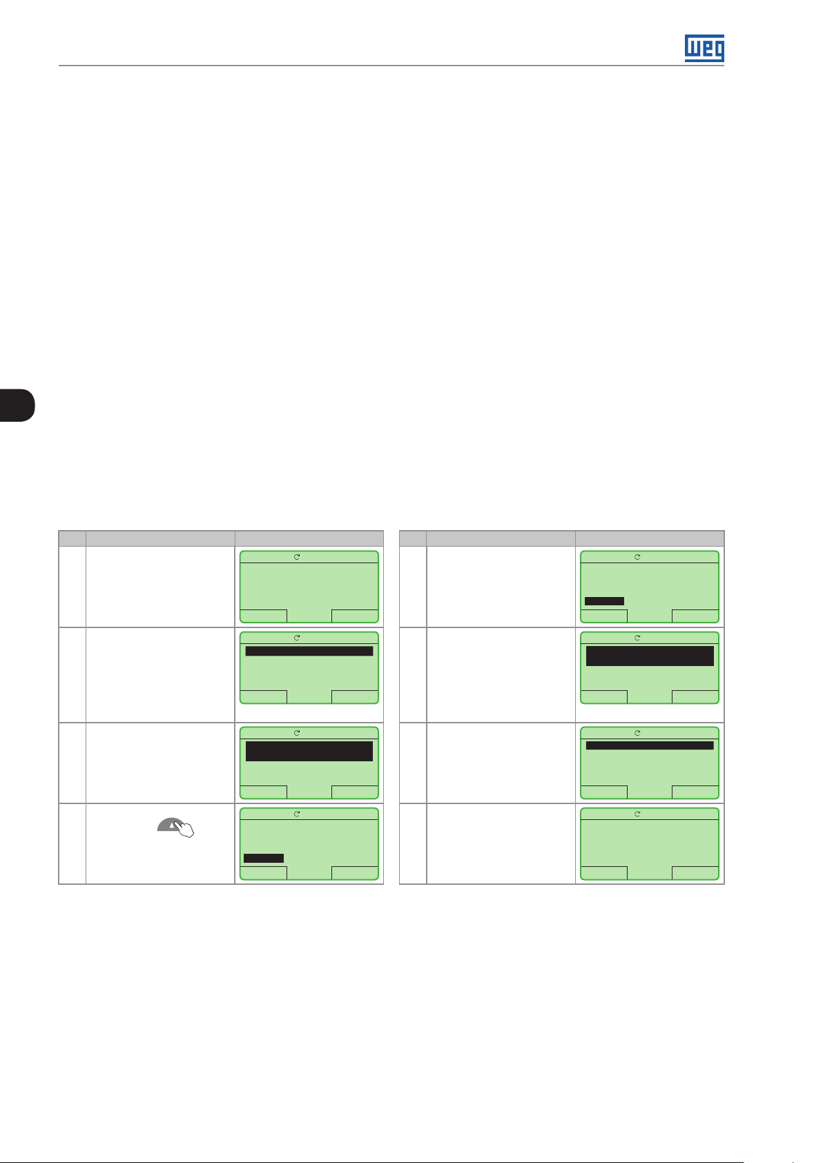
First Time Power-Up and Start-Up
12. Mechanically uncouple the motor from the load.
If the motor cannot be uncoupled, make sure that the chosen direction of rotation (forward or reverse) will not
result in personnel injury and/or equipment damage.
13. Command the drive, perform the DC link pre-charge and close the main contactor/circuit breaker.
14. Check the success of the energization.
15. The display must show the standard monitoring screen (Figure 4.3 on page 4-3 (a)), the status LED must
turn on and remain on in green.
5.2 S TART- UP
The start-up in the V/f mode is simply explained in three steps, using the programming facilities with the existing
parameter groups Oriented Start-Up and Basic Application.
Sequence:
5
1. Set the password to change parameters.
2. Execute the Oriented Start-up routine.
3. Set the parameters of the Basic Application group.
5. 2 .1 Password Setting in P0000
Step Action/Result Display Indication Step Action/Result Display Indication
1 - Monitoring mode
- Press "Menu" (rigth soft
key)
2 - Group "00 ALL
PARAMETERS" is already
selected
- Press "Select"
3 - Parameter "Access to
Parameters P0000: 0" is
already selected
- Press "Select"
4 - To set the password, press
the Up Arrow until
number 5 is displayed in the
keypad
Ready
LOC
0 rpm
0.0 A
0.0 Hz
15:45 Menu
Ready
Ready
Ready
LOC
00 TODOS PARAMETROS
01 GRUPOS PARAMETROS
02 START-UP ORIENTADO
03 PARAM. ALTERADOS
Sair 15:45 Selec.
LOC
Acesso aos Parametros
P0000: 0
Referencia Velocidade
P0001: 90 rpm
Sair 15:45 Selec.
LOC
P0000
Acesso aos Parametros
0
Sair 15:45 Salvar
0rpm
0rpm
0rpm
0rpm
5 - When number 5 is
displayed in the keypad,
press "Save"
6 - If the setting has been
properly performed, the
keypad should display
"Access to Parameters
P0000: 5"
- Press "Return" (left soft
key)
7 - Press "Return"
8 - The display returns to the
monitoring mode
Ready
LOC
P0000
Acesso aos Parametros
5
Sair 15:45 Salvar
Ready
Ready
Ready
LOC
Acesso aos Parametros
P0000: 5
Referencia Velocidade
P0001: 90 rpm
Sair 15:45 Selec.
LOC
00 TODOS PARAMETROS
01 GRUPOS PARAMETROS
02 START-UP ORIENTADO
03 PARAM. ALTERADOS
Sair 15:45 Selec.
LOC
0 rpm
0.0 A
0.0 Hz
15:45 Menu
0rpm
0rpm
0rpm
0rpm
Figure 5.1: Steps for allowing parameters modification via P0000
5.2.2 Oriented Start-up
There is a group of parameters named ”Oriented Start-up” that makes the inverter settings easier. Inside this group,
there is a parameter – P0317 – that shall be set to enter into the Oriented Start-up routine.
The Oriented Start-up routine allows you to quickly set up the inverter for operation with the line and motor used.
This routine prompts you for the most commonly used parameters in a logic sequence.
In order to enter into the Oriented Start-up routine, follow the steps presented in Figure 5.2 on page 5-4, first
modifying parameter P0317 to 1 and then, setting all remaining parameters as they are prompted in the display.
5-2 | CFW-11M G2
Page 75

First Time Power-Up and Start-Up
The use of the Oriented Start-up routine for setting the inverter parameters may lead to the automatic modification
of other internal parameters and/or variables of the inverter
During the Oriented Start-up routine, the message “Config” will be displayed at the left top corner of the keypad.
Step Action/Result Display Indication Step Action/Result Display Indication
1 - Monitoring mode
- Press "Menu" (right soft
key)
Ready
LOC
0 rpm
0.0 A
0.0 Hz
13:48 Menu
0rpm
11 - If needed, change the
value of P0298 according
to the inverter application.
To do so, press "Select".
This modification will affect
P0156, P0157, P0158,
P0401, P0404 and P0410
(this last one only if P0202 =
0, 1, or 2 - V/f control). The
time and the activation level
of the overload protection
will be affected as well
Config
LOC
Tensao Nominal Rede
P0296: 500 - 525 V
Aplicacao
P0298: Uso Pesado
Reset 13:48 Selec.
0rpm
2 - Group "00 ALL
PARAMETERS" has been
already selected
3 - Group "01 PARAMETER
GROUPS" is selected
4 - Group "02 ORIENTED
STA R T- U P " is then selected
- Press "Select"
5 - Parameter "Oriented
Start-Up P0317: No" has
been already selected
- Press "Select"
Ready
Ready
Ready
Ready
LOC
00 TODOS PARAMETROS
01 GRUPOS PARAMETROS
02 START-UP ORIENTADO
03 PARAM. ALTERADOS
Sair 13:48 Selec.
LOC
00 TODOS PARAMETROS
01 GRUPOS PARAMETROS
02 START-UP ORIENTADO
03 PARAM. ALTERADOS
Sair 13:48 Selec.
LOC
00 TODOS PARAMETROS
01 GRUPOS PARAMETROS
02 START-UP ORIENTADO
03 PARAM. ALTERADOS
Sair 13:48 Selec.
LOC
Start-Up Orientado
P0317: Nao
Sair 13:48 Selec.
0rpm
0rpm
0rpm
0rpm
12 - If needed, change the
value of P0398 according
to the motor service factor
To do so, press "Select"
This modification will affect
the current value and the
activation time of the motor
overload function
13 - If needed, change the
value of P0400 according
to the motor rated voltage
To do so, press "Select"
This modification adjusts the
output voltage by a factor x
= P0400/P0296
14 - If needed, change the
value of P0401 according
to the motor rated current.
To do so, press "Select".
This modification will affect
P0156, P0157, P0158, and
P0 410
15 - If needed, set P0402
according to the motor rated
speed. To do so, press
"Select". This modification
affects P0122 to P0131,
P0133, P0134, P0135,
P0182, P0208, P0288, and
P0289
Config
Config
Config
Config
LOC
Aplicacao
P0298: Uso Pesado
Fator Servico do Motor
P0398: 1.15
Reset 13:48 Selec.
LOC
Fator Servico do Motor
P0398: 1.15
Tensao Nominal Motor
P0400: 525 V
Reset 13:48 Selec.
LOC
Tensao Nominal Motor
P0400: 440V
Corrente Nominal Motor
P0401: 30.2 A
Reset 13:48 Selec.
LOC
Corrente Nominal Motor
P0401: 30.2 A
Rotacao Nom. Motor
P0402: 1750 rpm
Reset 13:48 Selec.
0rpm
0rpm
0rpm
0rpm
5
6 - The value of "P0317 =
[000] No" is displayed
7 - The parameter value is
modified to "P0317 = [001]
Yes "
- Press "Save"
Ready
LOC
P0317
Start-Up Orientado
[000] Nao
Sair 13:48 Salvar
Ready
LOC
P0317
Start-Up Orientado
[001] Sim
Sair 13:48 Salvar
0rpm
0rpm
16 - If needed, set P0403
according to the motor rated
frequency. To do so, press
"Select". This modification
affects P0402
17 - If needed, change the value
of P0404 according to the
motor rated power
To do so, press "Select"
This modification affects
P0 410
Config
Config
LOC
Rotacao Nom. Motor
P0402: 1750 rpm
Frequencia Nom. Motor
P0403: 50 Hz
Reset 13:48 Selec.
LOC
Frequencia Nom. Motor
P0403: 50 Hz
Potencia Nom. Motor
P0404: 30hp 22kW
Reset 13:48 Selec.
CFW-11M G2 | 5-3
0rpm
0rpm
Page 76

First Time Power-Up and Start-Up
Step Action/Result Display Indication Step Action/Result Display Indication
8 - At this point the Oriented
Start-up routine starts
and the "Config" status
is displayed at the top left
corner of the keypad
- The parameter "Language
P0201: English" is already
selected
- If needed, change the
language by pressing
"Select".Then, press
or to scroll
through the available options
and press "Save" to select a
different language
Config
LOC
Idioma
P0201: Portugues
Tipo de Controle
P0202: V/F 60 HZ
Reset 13:48 Selec.
0rpm
18 - This parameter will only be
visible if the encoder board
ENC1 is installed in the
inverter
- If there is an encoder
connected to the motor,
set P0405 according to the
encoder pulses number. To
do so, press "Select"
Config
LOC
Potencia Nom. Motor
P0404: 30hp 22kW
Numero Pulsos Encoder
P0405: 1024 ppr
Reset 13:48 Selec.
0rpm
9 - If needed, change the value
of P0202 according to the
type of control. To do so,
5
press "Select"
- The settings listed here
are valid only for P0202 =
Config
LOC
Idioma
P0201: Portugues
Tipo de Controle
P0202: V/F 60 HZ
Reset 13:48 Selec.
0rpm
0 (V/f 60 Hz) or P0202 = 1
19 - If needed, set P0406
according to the motor
ventilation. To do so, press
"Select"
- To complete the Oriented
Start-up routine, press
"Reset" (left soft key) or
Config
LOC
Numero Pulsos Encoder P0405:
1024 ppr
Ventilacao do Motor
P0406: Autoventilado
Reset 13:48 Selec.
0rpm
(V/f 50 Hz). For other options
(Adjustable V/f, VVW, or
Vector modes), please
refer to the programming
manualulte o manual de
programação
10 - If needed, change the value
of P0296 according to the
line rated voltage
To do so, press "Select"
This modification will affect
P0151, P0153, P0185,
Config
LOC
Tipo de Controle
P0202: V/F 50 HZ
Tensao Nominal Rede
P0296: 500 - 525 V
Reset 13:48 Selec.
0rpm
20 - After few seconds, the
display returns to the
monitoring mode
Ready
LOC
0 rpm
0.0 A
0.0 Hz
13:48 Menu
0rpm
P0321, P0322, P0323, and
P0400
Figure 5.2: Oriented start-up
5.2.3 Setting of the Basic Application Parameters
After running the Oriented Start-up routine and properly setting the parameters, the inverter is ready to operate
in the V/f mode.
The inverter has a series of other parameters that allow its adaptation to different applications. This manual contains
some basic parameters whose setting is necessary in most cases. In order to simplify this task, there is a group
called Basic Application. To set the parameters contained in the Basic Application group, follow the sequence of
Figure 5.6 on page 5-11. For further details, refer to the programming manual of the CFW-11.
After the setting of those parameters, the start-up in the V/f mode will be completed.
5-4 | CFW-11M G2
Page 77

First Time Power-Up and Start-Up
Step Action/Result Display Indication Step Action/Result Display Indication
1 - Monitoring mode
- Press "Menu" (right soft
key)
2 - Group "00 ALL
PARAMETERS" has been
already selected
3 - Group "01 PARAMETER
GROUPS" is then selected
4 - Group "02 ORIENTED
STA R T- U P " is then selected
Ready
LOC
0 rpm
0.0 A
0.0 Hz
15:45 Menu
Ready
Ready
Ready
LOC
00 TODOS PARAMETROS
01 GRUPOS PARAMETROS
02 START-UP ORIENTADO
03 PARAM. ALTERADOS
Sair 15:45 Selec.
LOC
00 TODOS PARAMETROS
01 GRUPOS PARAMETROS
02 START-UP ORIENTADO
03 PARAM. ALTERADOS
Sair 15:45 Selec.
LOC
00 TODOS PARAMETROS
01 GRUPOS PARAMETROS
02 START-UP ORIENTADO
03 PARAM. ALTERADOS
Sair 15:45 Selec.
0rpm
0rpm
0rpm
0rpm
6 - Group "04 BASIC
APPLICATION" is selected
- Press "Select"
7 - Parameter "Acceleration
Time P0100: 20.0 s" has
been already selected
- If needed, set P0100
according to the desired
acceleration time. To do so,
press "Select"
- Proceed similarly until all
parameters of group "04
BASIC APPLICATION" have
been set. When finished,
press "Return" (left soft key)
8 - Press "Return"
9 - The display returns to the
monitoring mode and the
inverter is ready to run
Ready
Ready
Ready
Ready
LOC
01 GRUPOS PARAMETROS
02 START-UP ORIENTADO
03 PARAM. ALTERADOS
04 APLICACAO BASICA
Sair 15:45 Selec.
LOC
Tempo Aceleracao
P0100: 20.0s
Tempo Desaceleracao
P0101: 20.0s
Sair 15:45 Selec.
LOC
01 GRUPOS PARAMETROS
02 START-UP ORIENTADO
03 PARAM. ALTERADOS
04 APLICACAO BASICA
Sair 15:45 Selec.
LOC
0 rpm
0.0 A
0.0 Hz
15:45 Menu
0rpm
0rpm
0rpm
5
0rpm
5 - Group "03 CHANGED
PARAMETERS" is selected
Ready
LOC
00 TODOS PARAMETROS
01 GRUPOS PARAMETROS
02 START-UP ORIENTADO
03 PARAM. ALTERADOS
Sair 15:45 Selec.
0rpm
Figure 5.3: Setting of the basic application parameters
CFW-11M G2 | 5-5
Page 78

First Time Power-Up and Start-Up
Table 5.1: Parameters comprised in the basic application group
Parameter Name Description
P0100 Acceleration time - Defines the time to linearly accelerate from 0 up to the
Setting
Range
0.0 to 999.0 s 20.0 s
maximum speed (P0134)
- If set to 0.0 s, it means no acceleration ramp
P0101 Deceleration time - Defines the time to linearly decelerate from the maximum
0.0 to 999.0 s 20.0 s
speed (P0134) up to 0
- If set to 0.0 s, it means no deceleration ramp
P0133 Minimum speed - Defines the minimum and maximum values of the speed
reference when the drive is enabled
0 to 18000
rpm
- These values are valid for any reference source
P0134 Maximum speed 1800 rpm
Reference
P0134
P0133
Factory
Setting
90 rpm
(60 Hz motor)
75 rpm
(50 Hz motor)
(60 Hz motor)
1500 rpm
(50 Hz motor)
User
Setting
5
0.......................10 V
0
Alx signal
0.......................20 mA
4 mA ................20 mA
10 V ..................0
20 mA ..............0
20 mA ..............4 mA
P0135 Max. output
current
- Avoids motor stall under torque overload condition during the
acceleration or deceleration
- The factory default setting is for "Ramp Hold": if the motor
0.2 x I
2 x I
nom-HD
nom-HD
a
1.5 x I
nom-HD
current exceeds the value set at P0135 during the acceleration
or deceleration, the motor speed will not be increased
(acceleration) or decreased (deceleration) anymore. When
the motor current reaches a value below the programmed in
P0135, the motor speed is again increased or decreased
- Other options for the current limitation are available. Refer to
the CFW-11 programming manual
Motor current Motor current
P0136 Manual torque
Boost
P013 5
Speed
Ramp
acceleration
(P0100)
During
acceleration
- Operates in low speeds, modi fying the output voltage x frequency
curve to keep the torque constant
P013 5
TimeTime
Speed
Ramp
deceleration
(P0101)
TimeTime
During
deceleration
0 to 9 1
- Compensates the voltage drop at the motor stator resistance.
This function operates in low speeds increasing the inverter
output voltage to keep the torque constant in the V/f mode
- The optimal setting is the smallest value of P0136 that allows the
motor to start satisfactorily. An excessive value will considerably
increase the motor current in low speeds, and may result in a
fault (F048, F051, F071, F072, F078 or F183) or alarm (A046, A047,
A050 or A110) condition
5-6 | CFW-11M G2
Rated
0,5 x rated
Output voltage
P0136 = 9
0
Nrat/2 Nrat
P0136 = 0
Speed
Page 79

Table 5.2: Main read only parameters
Parameter Description Setting Range
P0001 Speed Reference 0 to 18000 rpm
P0002 Motor Speed 0 to 18000 rpm
P0003 Motor Current 0.0 to 4500.0 A
P0004 DC Link Voltage (Ud) 0 to 2000 V
P0005 Motor Frequency 0.0 to 300.0 Hz
P0006
P0007 Motor Voltage 0 to 2000 V
P0009 Motor Torque -1000.0 to 1000.0 %
P0 010 Output Power 0.0 to 6553.5 kW
P0 0 12 DI8 to DI1 Status 0000h to 00FFh
P0 013 DO5 to DO1 Status 0000h to 001Fh
P0 018 AI1 Value -100.00 to 100.00 %
P0 019 AI2 Value -100.00 to 100.00 %
P0020 AI3 Value -100.00 to 100.00 %
P0021 AI4 Value -100.00 to 100.00 %
P0023 Software Version 0.00 to 655.35
P0027 Accessories Config. 1 Hexadecimal code
P0028 Accessories Config. 2
P0029 Power Hardware Config. Hexadecimal code
P0030 IGBTs Temperature U -20.0 to 150.0 °C
P0031 IGBTs Temperature V -20.0 to 150.0 °C
P0032 IGBTs Temperature W -20.0 to 150.0 °C
P0033 Rectifier Temperature -20.0 to 150.0 °C
P0034 Internal Air Temp. -20.0 to 150.0 °C
P0036 Fan Heatsink Speed 0 to 15000 rpm
P0037 Motor Overload Status 0 to 100 %
P0038 Encoder Speed 0 to 65535 rpm
P0040 PID Process Variable 0.0 to 100.0 %
P0041 PID Setpoint Value 0.0 to 100.0 %
P0042 Time Powered 0 to 65535h
P0043 Time Enabled 0.0 to 6553.5h
P0044 kWh Output Energy 0 to 65535 kWh
P0045 Fan Enabled Time 0 to 65535h
P0048 Present Alarm 0 to 999
P0049 Present Fault 0 to 999
P0050 Last Fault 0 to 999
P0051 Last Fault Day/Month 00/00 to 31/12
P0052 Last Fault Year 00 to 99
P0053 Last Fault Time 00:00 to 23:59
P0054 Second Fault 0 to 999
P0055 Second Fault Day/Month 00/00 to 31/12
P0056 Second Fault Year 00 to 99
P0057 Second Fault Time 00:00 to 23:59
P0058 Third Fault 0 to 999
P0059 Third Fault Day/Month 00/00 to 31/12
P0060 Third Fault Year 00 to 99
P0061 Third Fault Time 00:00 to 23:59
P0062 Fourth Fault 0 to 999
P0063 Fourth Fault Day/Month 00/00 to 31/12
P0064 Fourth Fault Year 00 to 99
P0065 Fourth Fault Time 00:00 to 23:59
P0066 Fifth Fault 0 to 999
P0067 Fifth Fault Day/Month 00/00 to 31/12
P0068 Fifth Fault Year 00 to 99
VFD Status 0 = Ready
1 = Run
2 = Undervoltage
3 = Fault
4 = Self-tuning
5 = Configuration
6 = DC-Braking
7 = STO
representing the identified
accessories. Refer to
Chapter 7 ACCESSORIES
on page 7-1
according to the available
models and option kits.
Refer to the programming
manual for a complete
code list
(-4 °F to 302 °F)
(-4 °F to 302 °F)
(-4 °F to 302 °F)
(-4 °F to 302 °F)
(-4 °F to 302 °F)
First Time Power-Up and Start-Up
Parameter Description Setting Range
P0069 Fifth Fault Time 00:00 to 23:59
P0070 Sixth Fault 0 to 999
P0071 Sixth Fault Day/Month 00/00 to 31/12
P0072 Sixth Fault Year 00 to 99
P0073 Sixth Fault Time 00:00 to 23:59
P0 074 Seventh Fault 0 to 999
P0075 Seventh Fault Day/Month 00/00 to 31/12
P0076 Seventh Fault Year 00 to 99
P0077 Seventh Fault Time 00:00 to 23:59
P0078 Eighth Fault 0 to 999
P0079 Eighth Fault Day/Month 00/00 to 31/12
P0080 Eighth Fault Year 00 to 99
P0081 Eighth Fault Time 00:00 to 23:59
P0082 Ninth Fault 0 to 999
P0083 Ninth Fault Day/Month 00/00 to 31/12
P0084 Ninth Fault Year 00 to 99
P0085 Ninth Fault Time 00:00 to 23:59
P0086 Tenth F a u l t 0 to 999
P0087 Tenth Fault Day/Month 00/00 to 31/12
P0088 Tenth Fault Year 00 to 99
P0089 Tenth Fault Time 00:00 to 23:59
P0090 Current At Last Fault 0.0 to 4000.0 A
P0091 DC Link At Last Fault 0 to 2000 V
P0092 Speed At Last Fault 0 to 18000 rpm
P0093 Reference Last Fault 0 to 18000 rpm
P0094 Frequency Last Fault 0.0 to 300.0 Hz
P0095 Motor Volt. Last Fault 0 to 2000 V
P0096 DIx Status Last Fault 0000h to 00FFh
P0097 DOx Status Last Fault 0000h to 001Fh
P0800 Phase U Book 1 Temper -20 to 150 ºC (-4 ºF to
302 ºF)
P0801 Phase V Book 1 Temper -20 to 150 ºC (-4 ºF to
302 ºF)
P0802 Phase W Book 1 Temper -20 to 150 ºC (-4 ºF to
302 ºF)
P0803 Phase U Book 2 Temper -20 to 150 ºC (-4 ºF to
302 ºF)
P0804 Phase V Book 2 Temper -20 to 150 ºC (-4 ºF to
302 ºF)
P0805 Phase W Book 2 Temper -20 to 150 ºC (-4 ºF to
302 ºF)
P0806 Phase U Book 3 Temper -20 to 150 ºC (-4 ºF to
302 ºF)
P0807 Phase V Book 3 Temoer -20 to 150 ºC (-4 ºF to
302 ºF)
P0808 Phase W Book 3 Temoer -20 to 150 ºC (-4 ºF to
302 ºF)
P0809 Phase U Book 4 Temper -20 to 150 ºC (-4 ºF to
302 ºF)
P0 810 Phase V Book 4 Temper -20 to 150 ºC (-4 ºF to
302 ºF)
P0811 Phase W Book 4 Temper -20 to 150 ºC (-4 ºF to
302 ºF)
P0 812 Phase U Book 5 Temper -20 to 150 ºC (-4 ºF to
302 ºF)
P0 813 Phase V Book 5 Temper -20 to 150 ºC (-4 ºF to
302 ºF)
P0 8 14 Phase W Book 5 Temper -20 to 150 ºC (-4 ºF to
302 ºF)
P0 815 Phase U Book 1 Current -1000 to 1000 A
P0 816 Phase V Book 1 Current -1000 to 1000 A
P0 8 17 Phase W Book 1 Current -1000 to 1000 A
P0 818 Phase U Book 2 Current -1000 to 1000 A
P0 819 Phase V Book 2 Current -1000 to 1000 A
P0820 Phase W Book 2 Current -1000 to 1000 A
P0821 Phase U Book 3 Current -1000 to 1000 A
P0822 Phase V Book 3 Current -1000 to 1000 A
P0823 Phase W Book 3 Current -1000 to 1000 A
P0824 Phase U Book 4 Current -1000 to 1000 A
P0825 Phase V Book 4 Current -1000 to 1000 A
P0826 Phase W Book 4 Current -1000 to 1000 A
P0827 Phase U Book 5 Current -1000 to 1000 A
P0828 Phase V Book 5 Current -1000 to 1000 A
P0829 Phase W Book 5 Current -1000 to 1000 A
5
CFW-11M G2 | 5-7
Page 80

First Time Power-Up and Start-Up
5.3 SETTING DATE AND TIME
Step Action/Result Display Indication
1 Monitoring mode
- Press "Menu" (right soft
key)
Ready
LOC
0 rpm
0.0 A
0rpm
0.0 Hz
16:10 Menu
2 - Group "00 ALL
PARAMETERS" is already
selected
3 - Group "01 PARAMETER
GROUPS" is selected
- Press "Select"
5
4 - A new list of groups is
displayed and group "20
Ramps" is selected
- Press until you
reach group "30 HMI"
5 - Group "30 HMI" is
selected
- Press "Select"
6 - Parameter "D ay P019 4" is
already selected
- If needed, set P0194
according to the actual day
To do so, press "Select"
Ready
Ready
Ready
Ready
Ready
LOC
00 TODOS PARAMETROS
01 GRUPOS PARAMETROS
02 START-UP ORIENTADO
03 PARAM. ALTERADOS
Sair 16:10 Selec.
LOC
00 TODOS PARAMETROS
01 GRUPOS PARAMETROS
02 START-UP ORIENTADO
03 PARAM. ALTERADOS
Sair 16:10 Selec.
LOC
20 Rampas
21 Refer. Velocidade
22 Limites Velocidade
23 Controle V/F
Sair 16:10 Selec.
LOC
27 Lim. Barram.CC V/F
28 Frenag. Reostatica
29 Controle Vetorial
30 HMI
Sair 16:10 Selec.
LOC
Dia
P0194: 06
Mes
P0195: 10
Sair 16:10 Selec.
0rpm
0rpm
0rpm
0rpm
0rpm
Step Action/Result Display Indication
7 - Once the setting of P0199
is over, the Real Time Clock
is now updated
- Press "Return" (left soft
key)
8 - Press "Return"
9 - Press "Return"
10 - The display is back to the
monitoring mode
Ready
Ready
Ready
Ready
LOC
Minutos
P0198: 11
Segundos
P0199: 34
Sair 18:11 Selec.
LOC
27 Lim. Barram.CC V/F
28 Frenag. Reostatica
29 Controle Vetorial
30 HMI
Sair 18:11 Selec.
LOC
00 TODOS PARAMETROS
01 GRUPOS PARAMETROS
02 START-UP ORIENTADO
03 PARAM. ALTERADOS
Sair 18:11 Selec.
LOC
0 rpm
0.0 A
0.0 Hz
18:11 Menu
0rpm
0rpm
0rpm
0rpm
and then, or
to change P0194 value
- Follow the same steps
to set parameters "Month
P0195" to "Seconds P0199"
Figure 5.4: Date and time setting
5.4 LOCKING OF PARAMETER MODIFICATION
In case you want to prevent unauthorized people from changing parameters, just change the content of P0000 to
a value different from 5. Follow basically the same procedure presented in Item 5.2.1 Password Setting in P0000
on page 5-2.
5.5 HOW TO CONNECT A PC
NOTE!
Always use standard host/device shielded USB cable. Cables without shield may cause
communication errors.
Recommended cables: Samtec:
USBC-AM-MB-B-B-S-1 (1 meter).
USBC-AM-MB-B-B-S-2 (2 meters).
USBC-AM-MB-B-B-S-3 (3 meters).
The USB connection is galvanically isolated from the mains power supply and from other high
voltages internal to the inverter. However, the USB connection is not isolated from the Protective
Ground (PE). Use an isolated notebook for the USB connection or a desktop connected to the
same Protective Ground (PE) of the inverter.
5-8 | CFW-11M G2
Page 81

First Time Power-Up and Start-Up
Install the SuperDrive G2 software to control motor speed, view, or edit inverter parameters through a personal
computer (PC).
Basic procedures for transferring data from the PC to the inverter:
1. Install the SuperDrive G2 software on the PC.
2. Connect the PC to the inverter via USB cable.
3. Start the SuperDrive G2.
4. Select “Open” and the files stored on the PC are shown.
5. Select the proper file.
6. Use the function "Write Parameters to the Drive".
All parameters are now transferred to the inverter.
For further details and other functions related to the SuperDrive G2, refer to the Manual of the SuperDrive.
5
5.6 FLASH MEMORY MODULE
Location according to Figure 5.5 on page 5-9.
Flash Memory Module
Figure 5.5: Detail of location of the flash memory module
Features:
Store a copy of the inverter parameters.
Transfer parameters stored in the FLASH memory to the inverter.
Transfer firmware stored in the FLASH memory to the inverter.
Store programs created by the SoftPLC.
CFW-11M G2 | 5-9
Page 82

First Time Power-Up and Start-Up
Whenever the inverter is powered up, this program is transferred to the RAM memory located in the inverter
control board and executed.
Refer to the CFW-11 programming manual and to SoftPLC manual for further details.
ATTENTION!
Before installing or removing the FLASH memory module, disconnect the inverter power supply and
wait for the complete discharge of the capacitors.
5.7 OPERATION WITH A REDUCED NUMBER OF POWER UNITS
The CFW-11M G2 can operate with a reduced number of UP11 and reduced power for a short time. That operating
mote is called "Reduced Power Mode". It may be applied to critical processes in which you do not want to stop
a whole machine when one UP11 fails, enabling the operation with reduced power until you have a UP11 for
replacement.
5
The general scheme of a drive with 5 UP11 is shown in Figure 3.22 on page 3-18. The reduced power mode
works as a drive of up to 2 UP11.
Assuming that in the drive of Figure 3.22 on page 3-18, composed of 5 UP11, the UP11 number4 fails. In order
to reestablish the drive operation with reduced power (Reduced Power Mode), you must follow the steps below:
1. Disconnect the power supply from the drive.
2. Identify the defective UP11 (in this case, number 4).
3. Disconnect the power and control of the UP11 number 4, according to Figure 5.7 on page 5-12.
4. Move the control connections on the ICUP board, as shown in Figure 5.7 on page 5-12. Connect the control
cables of UP11 number 5 to position 4 of the ICUP board. Thus, UP11 5 becomes UP11 4.
5. Configure the new number of UP11 through DIP switch S2 located on the ICUP board, according to Table
3.17 on page 3-32.
6. Change DIP switch S1:4 to ON; thus, it will be informed to the control that the CFW-11M G2 drive is operating
with a reduced number of UP11.
ATTENTION!
It is recommended that the drive operate short of one UP11 at most.
7. Reconnect only the power supply of the drive control.
8. Alarm A420 will be indicated (Reduced Power Mode), informing that the CFW-11M G2 is operating in the
reduced power mode.
9. Check if parameters P0295 (Rat. Curr. ND/HD Inv.) and P0296 (Rated Line Voltage) are according to the voltage
and the number of connected UP11.
10. Set the following control parameters:
11. P0169: Maximum Torque Current +.
12. P0170: Maximum Torque Current -.
13. Parameters P0169 and P0170 must be set so that the maximum torque current will not exceed the maximum
inverter current. The values of those parameters are referenced to the motor rated current, as you can see in
Item 11.8.6 - Torque Current Limit of the CFW-11 programming manual.
5-10 | CFW-11M G2
Page 83

14. Connect the drive power source.
UC11
ICUP
XC40AUH1...WL1UH2...WL2UH3...WL3
First Time Power-Up and Start-Up
+UD
-UD
+UD
-UD
HMI
CC11
UP11
U
V
W
XC33
1
220 Vac
XC6
1
2
1
2
3
24 Vdc
+UD
-UD
XC60
XC60XC9XC67XC5
1
2
3
24 Vdc
XC33
1
2
220 Vac
UP11
XC6
1
2
24 Vdc
U
V
W
5
2
3
+UD
UP11
24 Vdc
XC6
-UD
U
V
W
U
V
MOTOR
W
3
XC40C
stop
Safety
XC40 XC40 XC40
UH...WL UH...WL UH...WLUH...WLUH...WL
XC33
Digital
Inputs
220 Vac
+UD
Dynamic
BR
Error_BR
Braking
XC40DXC40E
XC40XC40
UP11
-UD
U
V
XC6
W
4
UH4...WL4UH5...WL5 XC40B
XC33
220 Vac
24 Vdc
+UD
-UD
UP11
U
V
W
XC33
1 1 1
220 Vac
XC6
5
2 2 2
1 1 1
2 2 2
3 3 3
24 Vdc
Figure 5.6: Disconnection of the power and control cables of UP11 number 4
ATTENTION!
The execution of self-tuning when the inverter is operating in the Reduced Power Mode is not permitted.
CFW-11M G2 | 5-11
Page 84

First Time Power-Up and Start-Up
UC11
ICUP
XC40AUH1...WL1UH2...WL2UH3...WL3
+UD
-UD
+UD
-UD
UP11
U
V
W
XC33
1
220 Vac
XC6
1
2
1
2
3
24 Vdc
+UD
-UD
HMI
CC11
XC60
XC60XC9XC67XC5
UP11
U
V
W
5
1
2
3
24 Vdc
XC33
1
2
220 Vac
XC6
1
2
24 Vdc
2
3
+UD
UP11
24 Vdc
XC6
-UD
U
V
W
U
V
MOTOR
W
3
XC40C
Stop
Safety
XC40 XC40 XC40
UH...WL UH...WL UH...WLUH...WLUH...WL
XC33
Digital
Inputs
220 Vac
+UD
Dynamic
BR
Error_BR
Braking
XC40DXC40E
XC40XC40
UP11
-UD
U
V
XC6
W
4
UH4...WL4UH5...WL5 XC40B
XC33
5-12 | CFW-11M G2
220 Vac
24 Vdc
+UD
-UD
UP11
U
V
W
XC33
1 1 1
220 Vac
XC6
5
2 2 2
3 3 3
1 1 1
2 2 2
24 Vdc
Figure 5.7: Moving the control connections on the ICUP board
Page 85

Troubleshooting and Maintenance
6 TROUBLESHOOTING AND MAINTENANCE
This chapter presents:
The list of all faults and alarms.
Most probable causes for each fault and alarm.
The list of the most common problems and corrective actions.
Instructions for periodical inspections of the product and preventive maintenance.
6.1 OPERATION OF THE FAULTS
When a fault is detected ("FAULT" (FXXX)):
The PWM pulses are blocked.
The keypad displays the "FAULT" code and description.
The “STATUS” LED flashes red.
The output relay set to "NO FAULT" opens.
Some control circuitry data is saved in the EEPROM memory:
- Keypad and EP (Electronic Pot) speed references, in case the function "Reference backup" is enabled in P0120.
- The "FAULT" or alarm potentiometer code that occurred (shifts the last nine previous faults and alarms).
- The state of the motor overload function integrator.
- The state of the operating hours counter (P0043) and the powered-up hours counter (P0042).
Reset the inverter to return the drive to a "READY" condition in the event of a "FAULT". The following reset
options are available:
- Removing the power supply and reapplying it (power-on reset).
- Pressing the operator key (manual reset).
- Through the "Reset" soft key.
- Automatically by setting P0340 (auto-reset).
- Through a digital input: DIx = 20 (P0263 to P0270).
- When an alarm situation ("ALARM" (AXXX)) is detected:
The keypad displays the "ALARM" code and description.
The "STATUS" LED changes to yellow.
The PWM pulses are not blocked (the inverter is still operating).
6
CFW-11M G2 | 6-1
Page 86

Troubleshooting and Maintenance
6.2 FAULTS, ALARMS AND POSSIBLE CAUSES
Table 6.1: Faults, alarms and possible causes
Fault/Alarm Description Possible Causes
F020:
24Vdc Power Supply
Undervoltage
F0 21:
DC Link Undervoltage
6
F022:
DC Link Overvoltage
(1)
F030:
Power Module U Fault
(1)
F034:
Power Module V Fault
(1)
F038:
Power Module W Fault
A046:
High Load on the Motor
A0 47:
IGBTs Overload Alarm
F048:
IGBTs Overload Fault
F0 67:
Encoder /Motor Wiring Is
Inverted
F070:
Overcurrent/
Short circuit
F071:
Output Overcurrent
F072:
Motor Overload
Undervoltage on the 24Vdc power supply that
Voltage on the power supply below 22.8 Vdc.
feeds the control.
DC Link undervoltage condition occurred. Supply voltage too low, producing voltage on the
DC link below the minimum value (read value in
parameter P0004):
− Ud < 385 V - Supply voltage 380 V (P0296 = 1).
− Ud < 405 V – Supply voltage 400-415 V
(P0296 = 2).
− Ud < 446 V – Supply voltage 440-460 V
(P0296 = 3).
− Ud < 487 V - Supply voltage 480 V (P0296 = 4).
− Ud < 530 V – Supply voltage 500-525 V
(P0296 = 5).
− Ud < 696 V – Supply voltage 550-575 V
(P0296 = 6).
− Ud < 605 V - Supply voltage 600 V (P0296 = 7).
− Ud < 696 V – Supply voltage 660-690 V
(P0296 = 8).
Phase loss in the input.
Fault in the pre-charge circuit.
Parameter P0296 was set to a value above of the
power supply rated voltage.
DC Link overvoltage condition occurred. Supply voltage too high, producing voltage on the
DC link above the maximum value:
− Ud > 800 V - Models 380 - 480 V (P0296 = 1,
2, 3 and 4).
− Ud > 1000 V - Models 500-600 V (P0296 = 5,
6 and 7).
− Ud > 1200 V - Models 660-690 V (P0296 = 8).
Driven load inertia too high or deceleration ramp
too fast.
Setting of P0151 or P0153 or P0185 too high.
Desaturation of IGBT occured in Power Module U. Short circuit between phases U and V or U and
W of the motor.
Desaturation of IGBT occured in Power Module V. Short circuit between phases V and U or V and
W of the motor.
Desaturation of IGBT occured in Power Module W. Short circuit between phases W and U or W and
V of the motor.
Load is too high for the used motor
Note:
It may be disabled by setting P0348 = 0 or 2.
An IGBTs overload alarm occurred.
Setting of P0156, P0157 and P0158 too low for
the motor.
Overload on the motor shaft.
Inverter output current is too high.
Note:
It may be disabled by setting P0350 = 0 or 2.
An IGBTs overload fault occurred. Inverter output current is too high.
Fault related to the phase relation of the encoder
signals, if P0202 = 4 and P0408 = 2, 3 or 4.
Note:
U, V, W wiring to the motor is inverted.
Encoder channels A and B are inverted.
Error in the encoder assembly position.
- This error can only occur during self-tuning.
- This fault cannot be reset.
- In this case, de-energize the inverter, solve the
problem and then energize it.
Overcurrent or short circuit in the output, DC link
or braking resistor.
Short circuit between two motor phases.
Short circuit of the connecting cables of the
dynamic braking.
IGBT modules short circuited.
The inverter output current was too high for too
long.
Load inertia too high or acceleration ramp too fast.
Setting of P0135, P0169, P0170, P0171 and P0172
too high.
Motor overload fault.
Note:
- It can be disabled by setting P0348 = 0 or 3.
Setting of P156, P157 and P158 too low for the
mo tor.
Load on the motor shaft is too high.
6-2 | CFW-11M G2
Page 87

Fault/Alarm Description Possible Causes
F074:
Ground Fault
F076:
Motor Current Imbalance
F077:
DB Resistor Overload
F078:
Motor Overtemperature
F079:
Encoder Signal Fault
F080:
CPU Watchdog
F082:
Copy Function Fault
F084:
Auto-diagnosis Fault
A088:
Communication Lost
A090:
External Alarm
F0 91:
External Fault
F099:
Invalid Current Offset
A110 :
High Motor Temperature
A128 :
Timeout for Serial
Communicationt
A129:
Anybus Offline
A130:
Anybus Access Error
A133:
CAN Not Powered
Troubleshooting and Maintenance
A ground fault occured either in the cable between
the inverter and the motor or in the motor itself.
Note:
It may be disabled by setting P0343 = 0.
Motor current imbalance fault.
Note:
- It may be disabled by setting P0342 = 0.
The dynamic braking resistor overload protection
operated.
Fault related to PTC temperature sensor installed
on the motor.
Note:
- It can be disabled by setting P0351 = 0 or 3.
- It is necessary to program analog input and
output for PTC function.
Lack of encoder signals. Broken wiring between motor encoder and option
Watchdog fault on the microcontroller. Electric noise.
Fault while copying parameters. Attempt to copy parameters from the HMI to the
Auto-diagnosis fault. Defect on the inverter internal circuits.
Indicates a problem between the keypad and
control board communication.
External alarm via DI.
Note:
- It is necessary to program DI for "without external
alarm”.
External fault via DI.
Note:
- It is necessary to program DI for "without external
fa ul t ”.
Current measurement circuit is measuring a wrong
value for null current.
Alarm related to PTC temperature sensor installed
on the motor.
Note:
- It can be disabled by setting P0351 = 0 or 2.
- It is necessary to program analog input and
output for PTC function.
It indicates that the inverter stopped receiving valid
telegrams within a certain period.
Note:
- It can be disabled by setting P0314 = 0.0 s.
Alarm that indicates interruption in the Anybus-CC
communication.
Alarm that indicates error of access to the AnybusCC communication module.
Alarm of power supply missing on the CAN
controller.
Short circuit to the ground in one or more output
phases.
Motor cable capacitance too high, causing current
peaks in the output.
Loose connection or broken wiring between the
(4)
motor and inverter connection.
Vector control with wrong orientation.
Vector control with encoder, encoder wiring or
encoder motor connection inverted.
Excessive load inertia or desacceleration time
too short.
Motor shaft load is excessive.
Values of P0154 and P0155 programmed
incorrectly.
Load on the motor shaft is too high.
Load cycle is too high (high number of starts and
stops per minute).
High ambient temperature around the motor.
Loose connection or short-circuit (resistance
< 60 Ω) in the wiring connected to the motor
termistor.
Motor thermistor not installed.
Motor shaft locked.
kit for encoder interface.
Encoder is defective.
inverter with incompatible software versions.
Loose keypad cable connection.
Electrical noise in the installation.
Wiring in the DI1 to DI8 inputs open (programmed
for “without external alarm”).
Wiring in the DI1 to DI8 inputs open (programmed
for “without external fault”).
Defect on the inverter internal circuits.
Excessive load at the motor shaft.
Excessive duty cycle (too many starts / stops
per minute).
Surrounding air temperature too high.
Loose connection or short-circuit (resistance
< 100 Ω) in the wiring connected to the motor
termistor.
Motor termistor is not installed.
Blocked motor shaft.
Check the wiring and grounding installation.
Make sure the inverter has sent a new message
within the time interval set at P0314.
PLC went to the idle status.
Programming error. Number of I/O words
programmed on the slave differs from the setting
on the master.
Loss of communication with the master (broken
cable, connector disconnected, etc.).
Anybus-CC module defective, not recognized or
incorrectly installed.
Conflict with WEG optional board.
Broken or loose cable.
Power supply is off.
6
CFW-11M G2 | 6-3
Page 88

Troubleshooting and Maintenance
Fault/Alarm Description Possible Causes
A134:
Bus Off
A135:
CANopen Communication
Error
A136:
Idle Master
A137:
DNet Connection Time out
(2)
A138:
Profibus DP Interface in Clear
Mode
(2)
A139:
Offline Profibus DP Interface
(2)
A140:
Profibus DP Module Access
6
Error
F150:
Motor Overspeed
F151:
FLASH Memory Module Fault
A152:
Internal Air High Temperature
F153:
Internal Air Overtemperature
A156:
Undertemperature
F156:
Undertemperature
F160:
Safety Stop Relay
F161:
Timeout PLC11 CFW-11
A162:
Incompatible PLC Firmware
A163:
Break Detect AI1
A164:
Break Detect AI2
A165:
Break Detect AI2
A166:
Break Detect AI2
A177:
Fan Replacement
A181:
Invalid Clock Value
Inverter CAN interface has entered into the bus-off
state.
Incorrect communication baud-rate.
Two nodes configured with the same address in
the network.
Wrong cable connection (inverted signals).
Alarm that indicates communication error. Communication problems.
Wrong master configuration/settings.
Incorrect configuration of the communication
objects.
Network master has entered into the idle state. PLC in IDLE mode.
Bit of the PLC command register set to zero (0).
I/O connection timeout - DeviceNet
communication alarm.
It indicates that the inverter received the command
from the DP Profibus network master to go into
Clear mode.
One or more allocated I/O connections went to
the timeout status.
Verify the network master status, making sure it
is in execution mode (Run).
Refer to the Profibus DP communication manual
for more information.
It indicates interruption in the communication
between the DP Profibus network master and the
inverter.
Check if the network master is correctly configured
and operating properly.
Check the network installation in general – cabling,
grounding.
For further information, refer to the Profibus DP
communication manual.
It indicates error in the access to the data of the
DP Profibus communication module.
Check if the DP profibus module is correctly fitted
in slot 3.
For further information, refer to the Profibus DP
communication manual.
Overspeed Fault.
Incorrect setting of P0161 and/or P0162.
Enabled when the real speed exceeds the value of
P0134 x (100 % + P0132) for more than 20 ms.
Fault on the Flash Memory Module (MMF-01). Flash memory module defective.
Check the connection of the FLASH memory
module.
Air temperature alarm high internal temperature
measured above 75 ºC (167 °F).
Note:
- It can be disabled by setting P0353 = 1 or 3.
High ambient temperature around the inverter
(> 40 °C (104 °F)).
High temperature inside the cabinet (> 40 °C
(104 °F)).
Failure of the internal air temperature measured
temperature above 80 ºC (176 °F).
Only 1 sensor indicates temperature below -30 ºC
Surrounding air temperature ≤ -30 °C (-22 °F).
(-22 °F).
Undertemperature fault (below -30 °C (-22 °F)) in
Surrounding air temperature ≤ -30 °C (-22 °F).
he IGBTs or rectifier measured by the temperature
sensors.
Safety Stop relay fault. It was only applied +24 Vdc to one STO input
(STO1 or STO2).
One of the relays is defective.
Refer to the programming manual of the PLC11-01 module available on www.weg.net.
It indicates that AI1 current reference (4-20 mA or
20-4 mA) is out of the range from 4 to 20 mA.
Cable of AI1 broken.
Poor contact on the signal connection on the
terminals.
It indicates that AI2 current reference (4-20 mA or
20-4 mA) is out of the range from 4 to 20 mA.
Cable of AI2 broken.
Poor contact on the signal connection on the
terminals.
It indicates that AI3 current reference (4-20 mA or
20-4 mA) is out of the range from 4 to 20 mA.
Cable of AI3 broken.
Poor contact on the signal connection on the
terminals.
It indicates that AI4 current reference (4-20 mA or
20-4 mA) is out of the range from 4 to 20 mA.
Cable of AI4 broken.
Poor contact on the signal connection on the
terminals.
Alarm to replace the fan (P0045 > 50000 hours).
Note:
Maximum number of hours of operation of the
heatsink fan exceeded.
- It may be disabled by setting P0354 = 0.
Invalid clock value alarm. Necessary to set the date and time in P0194 to
P0199.
HMI battery low, defective or not installed.
6-4 | CFW-11M G2
Page 89

Fault/Alarm Description Possible Causes
F182:
Pulse Feedback Fault
F183:
IGBTs Overload +Temperature
(3)
F186:
Sensor 1 Temperature
Fault
(3)
F187:
Sensor 2 Temperature
Fault
(3)
F188:
Sensor 3 Temperature
Fault
(3)
F189:
Sensor 4 Temperature
Fault
(3)
F190:
Sensor 5 Temperature
Fault
(3)
A191:
Sensor 1 Temperature
Alarm
(3)
A192:
Sensor 2 Temperature
Alarm
(3)
A193:
Sensor 3 Temperature
Alarm
(3)
A194:
Sensor 4 Temperature
Alarm
(3)
A195:
Sensor 5 Temperature
Alarm
(3)
A196:
Sensor 1 Cable Alarm
(3)
A197:
Sensor 2 Cable Alarm
(3)
A198:
Sensor 3 Cable Alarm
(3)
A199:
Sensor 4 Cable Alarm
(3)
A200:
Sensor 5 Cable Alarm
F228:
Serial Communication Timeout
F229:
Anybus Offline
F230:
Anybus Access Error
F233:
CAN Bus Power Failure
F234:
Bus Off
F235:
CANopen Communication
Error
F236:
Master in Idle
F237:
DeviceNet Connection
Timeout
(2)
F238:
Profibus DP Interface in Clear
Mode
Troubleshooting and Maintenance
Fault in the output pulse feedback. Defect on the internal circuits of the inverter.
Overtemperature related to IGBT overload
protection.
Temperature fault in sensor 1. High temperature on the motor.
Temperature fault in sensor 2. High temperature on the motor.
Temperature fault in sensor 3. High temperature on the motor.
Temperature fault in sensor 4. High temperature on the motor.
Temperature fault in sensor 5. High temperature on the motor.
Temperature alarm in sensor 1. High temperature on the motor.
Temperature alarm in sensor 2. High temperature on the motor.
Temperature alarm in sensor 3. High temperature on the motor.
Temperature alarm in sensor 4. High temperature on the motor.
Temperature alarm in sensor 5. High temperature on the motor.
Sensor 1 cable alarm. Short circuited temperature sensor.
Sensor 2 cable alarm. Short circuited temperature sensor.
Sensor 3 cable alarm. Short circuited temperature sensor.
Sensor 4 cable alarm.. Short circuited temperature sensor.
Sensor 5 cable alarm. Short circuited temperature sensor.
Refer to the RS-232/RS-485 Serial communication manual.
Refer to the Anybus-CC communication manual.
Refer to the CANopen communication manual and/or refer to the DeviceNet communication manual.
Refer to the CANopen communication manual.
Refer to the DeviceNet communication manual.
It indicates that the inverter received the command
from the DP Profibus network master to go into
Clear mode.
High ambient temperature around the inverter.
Operation in frequency < 10Hz with overload.
Problem in the wiring that connects the IOE-01
Module (02 or 03) to the sensor.
Problem in the wiring that connects the IOE-01
Module (02 or 03) to the sensor.
Problem in the wiring that connects the IOE-01
Module (02 or 03) to the sensor.
Problem in the wiring that connects the IOE-01
Module (02 or 03) to the sensor.
Problem in the wiring that connects the IOE-01
Module (02 or 03) to the sensor.
Check the network master status, ensuring it is
in the Run mode.
The fault indication will occur if P0313 = 5.
For further information, refer to the Profibus DP
communication manual.
6
CFW-11M G2 | 6-5
Page 90

Troubleshooting and Maintenance
Fault/Alarm Description Possible Causes
(2)
F239:
Offline Profibus DP Interface
(2)
F240:
Profibus DP Module
Access Error
A300:
High Temperature
IGBT U B1
F3 01:
Overtemperature
IGBT U B1
A303:
High Temperature
IGBT V B1
6
F304:
Overtemperature
IGBT V B1
A306:
High Temperature
IGBT W B1
F3 07:
Overtemperature
IGBT W B1
A309:
High Temperature
IGBT U B2
F310:
Overtemperature
IGBT U B2
A312:
High Temperature
IGBT V B2
F313:
Overtemperature
IGBT V B2
A315:
High Temperature
IGBT W B2
F316:
Overtemperature
IGBT W B2
A318:
High Temperature
IGBT U B3
F319:
Overtemperature
IGBT U B3
It indicates interruption in the communication
between the DP Profibus network master and
the inverter.
It indicates error in the access to the data of the
Profibus DP communication module.
Alarm of high temperature measured on the
temperature sensor (NTC) of the IGBT of phase U
of book 1. Measured temperature above 110 ºC
(230 °F).
Fault of overtemperature measured on the
temperature sensor (NTC) of the IGBT of phase U
of book 1. Measured temperature above 115 ºC
(239 °F).
Alarm of high temperature measured on the
temperature sensor (NTC) of IGBT of phase V of
book 1. Measured temperature above 110 ºC
(230 °F).
Fault of overtemperature measured on the
temperature sensor (NTC) of IGBT of phase V of
book 1. Measured temperature above 115 ºC
(239 °F).
Alarm of high temperature measured on the
temperature sensor (NTC) of IGBT of phase W of
book 1. Measured temperature above 110 ºC
(230 °F).
Fault of overtemperature measured on the
temperature sensor (NTC) of IGBT of phase W of
book 1. Measured temperature above 115 ºC
(239 °F).
Alarm of high temperature measured on the
temperature sensor (NTC) of IGBT of phase U of
book 2. Measured temperature above 110 ºC
(230 °F).
Fault of overtemperature measured on the
temperature sensor (NTC) of the IGBT of phase U
of book 2. Measured temperature above 115 ºC
(239 °F).
Alarm of high temperature measured on the
temperature sensor (NTC) of IGBT of phase V of
book 2. Measured temperature above 110 ºC
(230 °F).
Fault of overtemperature measured on the
temperature sensor (NTC) of IGBT of phase V of
book 2. Measured temperature above 115 ºC
(239 °F).
Alarm of high temperature measured on the
temperature sensor (NTC) of IGBT of phase W of
book 2. Measured temperature above 110 ºC
(230 °F).
Fault of overtemperature measured on the
temperature sensor (NTC) of IGBT of phase W
of book 2. Measured temperature above 115 ºC
(239 °F).
Alarm of high temperature measured on the
temperature sensor (NTC) of IGBT of phase U of
book 3. Measured temperature above 110 ºC
(230 °F).
Fault of overtemperature measured on the
temperature sensor (NTC) of the IGBT of phase U
of book 3. Measured temperature above 115 ºC
(239 °F).
Check if the network master is correctly configured
and operating properly.
Check the network installation in general – cabling,
grounding.
The fault indication will occur if P0313 = 5.
For further information, refer to the Profibus DP
communication manual.
Check if the DP Profibus Module is correctly fitted
in slot 3.
The fault indication will occur if P0313 = 5.
For further information, refer to the Profibus DP
communication manual.
High ambient temperature (> 45 °C (113 °F)) and
high output current.
Blocked or defective fan.
Fins of the book heatsink too dirty, hindering the
air flow.
6-6 | CFW-11M G2
Page 91

Fault/Alarm Description Possible Causes
A3 21:
High Temperature
IGBT V B3
F322:
Overtemperature
IGBT V B3
A324:
High Temperature
IGBT W B3
F325:
Overtemperature
IGBT W B3
A327:
High Temperature IGBT U B4
F328:
Overtemperature
IGBT U B4
A330:
High Temperature
IGBT V B4
F3 31:
Overtemperature
IGBT V B4
A333:
High Temperature
IGBT W B4
F334:
Overtemperature
IGBT W B4
A336:
High Temperature
IGBT U B5
F3 37:
Overtemperature
IGBT U B5
A339:
High Temperature
IGBT V B5
F340:
Overtemperature
IGBT V B5
A342:
High Temperature
IGBT W B5
F343:
IGBT Overtemperature
W B5
Alarm of high temperature measured on the
temperature sensor (NTC) of IGBT of phase V of
book 3. Measured temperature above 110 ºC
(230 °F).
Fault of overtemperature measured on the
temperature sensor (NTC) of IGBT of phase V of
book 3. Measured temperature above 115 ºC
(239 °F).
Alarm of high temperature measured on the
temperature sensor (NTC) of IGBT of phase W of
book 3. Measured temperature above 110 ºC
(230 °F).
Fault of overtemperature measured on the
temperature sensor (NTC) of IGBT of phase W
of book 3. Measured temperature above 115 ºC
(239 °F).
Alarm of high temperature measured on the
temperature sensor (NTC) of IGBT of phase U of
book 4. Measured temperature above 110 ºC
(230 °F).
Fault of overtemperature measured on the
temperature sensor (NTC) of the IGBT of phase U
of book 4. Measured temperature above 115 ºC
(239 °F).
Alarm of high temperature measured on the
temperature sensor (NTC) of IGBT of phase V of
book 4. Measured temperature above 110 ºC
(230 °F).
Fault of overtemperature measured on the
temperature sensor (NTC) of IGBT of phase V of
book 4. Measured temperature above 115 ºC
(239 °F).
Alarm of high temperature measured on the
temperature sensor (NTC) of IGBT of phase W of
book 4. Measured temperature above 110 ºC
(230 °F).
Fault of overtemperature measured on the
temperature sensor (NTC) of IGBT of phase W
of book 4. Measured temperature above 115 ºC
(239 °F).
Alarm of high temperature measured on the
temperature sensor (NTC) of IGBT of phase U of
book 5. Measured temperature above 110 ºC
(230 °F).
Fault of overtemperature measured on the
temperature sensor (NTC) of the IGBT of phase U
of book 5. Measured temperature above 115 ºC
(239 °F).
Alarm of high temperature measured on the
temperature sensor (NTC) of IGBT of phase V of
book 5. Measured temperature above 110 ºC
(230 °F).
Fault of overtemperature measured on the
temperature sensor (NTC) of IGBT of phase V of
book 5. Measured temperature above 115 ºC
(239 °F).
Alarm of high temperature measured on the
temperature sensor (NTC) of IGBT of phase W of
book 5. Measured temperature above 110 ºC
(230 °F).
Fault of overtemperature measured on the
temperature sensor (NTC) of IGBT of phase W
of book 5. Measured temperature above 115 ºC
(239 °F).
Troubleshooting and Maintenance
High ambient temperature (> 45 °C (113 °F)) and
high output current.
Blocked or defective fan.
Fins of the book heatsink too dirty, hindering the
air flow.
6
CFW-11M G2 | 6-7
Page 92

Troubleshooting and Maintenance
Fault/Alarm Description Possible Causes
A345:
High Load IGBT U B1
F346:
Overload on IGBT U B1
A348:
High Load IGBT V B1
F349:
Overload on IGBT V B1
A351:
High Load IGBT W B1
F352:
Overload on IGBT W B1
A354:
High Load IGBT U B2
F355:
Overload on IGBT U B2
A357:
High Load IGBT V B2
F358:
Overload on IGBT V B2
A360:
High Load IGBT W B2
F3 61:
6
Overload on IGBT W B2
A363:
High Load IGBT U B3
F364:
Overload on IGBT U B3
A366:
High Load IGBT V B3
F3 67:
Overload on IGBT V B3
A369:
High Load IGBT W B3
F370:
Overload on IGBT W B3
A372:
High Load IGBT U B4
F373:
Overload on IGBT U B4
A375:
High Load IGBT V B4
F376:
Overload on IGBT V B4
A378:
High Load IGBT W B4
F379:
Overload on IGBT W B4
A3 81:
High Load IGBT U B5
F382:
Overload on IGBT U B5
A384:
High Load IGBT V B5
F385:
Overload on IGBT V B5
A387:
High Load IGBT W B5
F388:
Overload on IGBT W B5
Alarm of overload on the IGBT of phase U of
bo o k 1.
Fault of overload on the IGBT of phase U of book
1.
Alarm of overload on the IGBT of phase V of
bo o k 1.
Fault of overload on the IGBT of phase V of book
1.
Alarm of overload on the IGBT of phase W of
bo o k 1.
Fault of overload on the IGBT of phase W of
bo o k 1.
Overload alarm on IGBT of phase U of
book 2.
Fault of overload on the IGBT of phase U of book
2.
Alarm of overload on the IGBT of phase V of book
2.
Fault of overload on the IGBT of phase V of
book 2.
Alarm of overload on the IGBT of phase W of book
2.
Fault of overload on the IGBT of phase W of book
2.
Alarm of overload on the IGBT of phase U of book
3.
Fault of overload on the IGBT of phase U of book
3.
Alarm of overload on the IGBT of phase V of book
3.
Fault of overload on the IGBT of phase V of book
3.
Alarm of overload on the IGBT of phase W of book
3.
Fault of overload on the IGBT of phase W of book
3.
Alarm of overload on the IGBT of phase U of book
4.
Fault of overload on the IGBT of phase U of book
4.
Alarm of overload on the IGBT of phase V of book
4.
Fault of overload on the IGBT of phase V of book
4.
Alarm of overload on the IGBT of phase W of book
4.
Fault of overload on the IGBT of phase W of book
4.
Alarm of overload on the IGBT of phase U of book
5.
Fault of overload on the IGBT of phase U of book
5.
Alarm of overload on the IGBT of phase V of book
5.
Fault of overload on the IGBT of phase V of book
5.
Alarm of overload on the IGBT of phase W of book
5.
Fault of overload on the IGBT of phase W of book
5.
High current in the inverter output (refer to Figure
8.1 on page 8-3).
High current in the inverter output (refer to Figure
8.1 on page 8-3).
6-8 | CFW-11M G2
Page 93

Fault/Alarm Description Possible Causes
A390:
Current Imbalance
Phase U B1
A3 91:
Current Imbalance
Phase V B1
A392:
Current Imbalance
Phase W B1
A393:
Current Imbalance
Phase U B2
A394:
Current Imbalance
Phase V B2
A395:
Current Imbalance
Phase W B2
A396:
Current Imbalance
Phase U B3
A397:
Current Imbalance
Phase V B3
A398:
Current Imbalance
Phase W B3
A399:
Current Imbalance
Phase U B4
A400:
Current Imbalance
Phase V B4
A4 01:
Current Imbalance
Phase W B4
Troubleshooting and Maintenance
Alarm of current imbalance of phase U book 1.
It indicates an imbalance of 20 % in the current
distribution between this phase and the smallest
current of the same phase in another book, only
when the current in this phase is higher than 75 %
of its rated value.
Alarm of current imbalance of phase V book 1.
It indicates an imbalance of 20 % in the current
distribution between this phase and the smallest
current of the same phase in another book, only
when the current in this phase is higher than 75 %
of its rated value.
Alarm of current imbalance of phase W book 1.
It indicates an imbalance of 20 % in the current
distribution between this phase and the smallest
current of the same phase in another book, only
when the current in this phase is higher than 75 %
of its rated value.
Alarm of current imbalance of phase U book 2.
It indicates an imbalance of 20 % in the current
distribution between this phase and the smallest
current of the same phase in another book, only
when the current in this phase is higher than 75 %
of its rated value.
Alarm of current imbalance of phase V book 2.
It indicates an imbalance of 20 % in the current
distribution between this phase and the smallest
current of the same phase in another book, only
when the current in this phase is higher than 75 %
of its rated value.
Alarm of current imbalance of phase W book 2.
It indicates an imbalance of 20 % in the current
distribution between this phase and the smallest
current of the same phase in another book, only
when the current in this phase is higher than 75 %
of its rated value.
Alarm of current imbalance of phase U book 3.
It indicates an imbalance of 20 % in the current
distribution between this phase and the smallest
current of the same phase in another book, only
when the current in this phase is higher than 75 %
of its rated value.
Alarm of current imbalance of phase V book 3.
It indicates an imbalance of 20 % in the current
distribution between this phase and the smallest
current of the same phase in another book, only
when the current in this phase is higher than 75 %
of its rated value.
Alarm of current imbalance of phase W book 3.
It indicates an imbalance of 20 % in the current
distribution between this phase and the smallest
current of the same phase in another book, only
when the current in this phase is higher than 75 %
of its rated value.
Alarm of current imbalance of phase U book 4.
It indicates an imbalance of 20 % in the current
distribution between this phase and the smallest
current of the same phase in another book, only
when the current in this phase is higher than 75 %
of its rated value.
Alarm of current imbalance of phase V book 4.
It indicates an imbalance of 20 % in the current
distribution between this phase and the smallest
current of the same phase in another book, only
when the current in this phase is higher than 75 %
of its rated value.
Alarm of current imbalance of phase W book 4.
It indicates an imbalance of 20 % in the current
distribution between this phase and the smallest
current of the same phase in another book, only
when the current in this phase is higher than 75 %
of its rated value.
Poor electrical connection between the DC link
and the power unit.
Poor electrical connection between the power unit
output and the motor.
Note: In case of quick accelerations and brakes,
this alarm may be momentarily indicated,
disappearing after some seconds. This does not
indicate a malfunction on the inverter. In case this
alarm persists when the motor in operating at
constant speed, it is an indication of abnormal
current distribution between the power units.
6
CFW-11M G2 | 6-9
Page 94

Troubleshooting and Maintenance
Fault/Alarm Description Possible Causes
A402:
Current Imbalance
Phase U B5
A403:
Current Imbalance
Phase V B5
A404:
Current Imbalance
Phase W B5
F406:
Overtemperature on the
Braking Module
F408:
Fault on the Cooling
System
6
F410:
External Fault
F412:
Overtemperature on the
Rectifier
F414:
Fault on the External Rectifier
A415:
High temperature on
the Rectifier
(5)
A700:
HMI Disconnected
(5)
F701:
HMI Disconnected
(5)
A702:
Inverter Disabled
(5)
A704:
Two Movements Enabled
(5)
A706:
Speed Reference Not
Programmed for SoftPLC
Alarm of current imbalance of phase U book 5.
It indicates an imbalance of 20 % in the current
distribution between this phase and the smallest
current of the same phase in another book, only
when the current in this phase is higher than 75 %
of its rated value.
Alarm of current imbalance of phase V book 5.
It indicates an imbalance of 20 % in the current
distribution between this phase and the smallest
current of the same phase in another book, only
when the current in this phase is higher than 75 %
Poor electrical connection between the DC link
and the power unit.
Poor electrical connection between the power unit
output and the motor.
Note: In case of quick accelerations and brakes,
this alarm may be momentarily indicated,
disappearing after some seconds. This does not
indicate a malfunction on the inverter. In case this
alarm persists when the motor in operating at
constant speed, it is an indication of abnormal
current distribution between the power units.
of its rated value.
Alarm of current imbalance of phase W book 5.
It indicates an imbalance of 20 % in the current
distribution between this phase and the smallest
current of the same phase in another book, only
when the current in this phase is higher than 75 %
of its rated value.
This fault/alarm is linked to the configuration of
parameters P0832 and P0833.
- Function of input DIM 1.
- Function of input DIM 2.
Fault on the cooling of the braking module.
Load inertia too high or deceleration ramp too fast.
Load on the motor shaft is too high.
Fault on pumps (drives with water cooling).
Fault on the panel ventilation.
Input DIM1 or DIM2 open.
Ambient temperature around the rectifier (>45 °C
(113 °F)) and output current too high.
Cooling problem on the rectifier.
Rectifier heatsink too dirty.
Undervoltage or phase loss in the rectifier input.
High ambient temperature around the rectifier and
high output current.
Rectifier heatsink too dirty.
Alarm or Fault linked to the disconnection of the
HMI.
RTC function block was enabled in the SoftPLC
application and the HMI is disconnected from
the inverter.
Alarm indicates the General Enable command is
Disabled.
The SoftPLC Run/Stop command is equal to Run
or a movement block has been enable while the
inverter is general disabled.
Two movements have been enabled. It occurs when two or more movement blocks are
simultaneously enabled.
Speed reference not programmed for SoftPLC. It occurs when a movement block has been
enabled and the speed reference has not been
configured for SoftPLC (check P0221 and P0222).
Models in which it may occur:
(1) In case of the CFW11M G2, the HMI does not indicated in which UP11 G2 the fault occurred. LEDs on the ICUP board indicate which UP11 caused the fault,
Figure 6.1 on page 6-10. When the reset is executed, the LEDs turn off and turn back on if the fault persists.
Figure 6.1: LEDs that indicate fault on the arms of the power units (desaturation)
(2) With Profibus DP module connected to slot 3 (XC43).
(3) With IOE-01 (02 or 03) module connected to slot 1 (XC41).
(4) Very long motor cables (longer than 100 meters) present a high parasite capacitance against the ground. The circulation of parasite currents through those
capacitances may cause the ground fault circuit activation and thus disabling the inverter with F074, immediately after the inverter enabling.
(5) All the models with a SoftPLC applicative
6-10 | CFW-11M G2
Page 95

Troubleshooting and Maintenance
NOTE!
The range from P0750 to P0799 is destined to the SoftPLC applicative user faults and alarms.
6.3 SOLUTIONS FOR THE MOST FREQUENT PROBLEMS
Table 6.2: Solutions for the most frequent problems
Problem Point to be Verifid Corrective Action
Motor does not start Incorrect wiring 1. Check all power and control connections. For instance, the
Analog reference (if used) 1. Check if the external signal is properly connected
Incorrect settings 1. Check if the parameters have correct values for the application
Fault 1. Check whether the inverter is disabled due to a fault condition
Stalled motor 1. Decrease the motor overload
Motor speed oscillates Loose connections 1. Stop the inverter, turn off the power supply, check and tighten
Defective speed reference
potentiometer
Oscillation of the external analog
reference
Incorrect settings (vector control) 1. Check parameters P0410, P0412, P0161, P0162, P0175 and
Motor speed too high or too low Incorrect settings
Motor does not reach the rated
speed, or motor speed starts
oscillating around the rated speed
(Vector Control)
Display is off Keypad connections 1. Check the inverter keypad connection
Low motor speed and P0009 =
P0169 or P0170 (motor operating
with torque limitation), for
P0202 = 4 - vector with encoder
(reference limits)
Control signal from the
analog reference (if used)
Motor nameplate 1. Check if the motor is according to the application requirements
Settings 1. Check P0410
IPS1 24 Vdc power supply
voltage
Encoder signals are inverted or
power connections are inverted
digital inputs set to Start/Stop, General Enable, or no external
error must be connected to the 24 Vdc or to DGND* terminals
(refer to Figure 3.39 on page 3-35 and Figure 3.40 on page
3-36)
2. Check the status of the control potentiometer (if used)
2. Make sure that the terminals XC1:13 and XC1:11 are not shorted
(short-circuit at the 24 Vdc power supply)
2. Increase P0136, P0137 (V/f), or P0169/P0170 (vector control)
all the power connections
2. Check all the internal connections of the inverter
1. Replace potentiometer
1. Identify the cause of the oscillation. If it is caused by electrical
noise, use shielded cables or separate them from the power
and control wiring
P0176
2. Refer to the Programming Manual
1. Check if the content of P0133 (minimum speed) and P0134
(maximum speed) are according to the motor and application
1. Check the level of the reference control signal
2. Check the programming (gains and offset) in P0232 to P0249
1. Check the connections of the control 24 Vdc power supply
2. Check if the power supply limits are according to Table 3.14 on
page 3-30
1. Check the signals A-A, B-B refer to the incremental encoder
interface manual. If signals are properly wired, invert two of the
output phases. For instance U and V
6
6.4 INFORMATION NECESSARY FOR CONTACTING TECHNICAL SUPPORT
NOTE!
For technical support and servicing, it is important to have the following information in hand:
Inverter model.
Serial number, manufacturing date and hardware revision indicated on the nameplate of the product
(see Chapter 2 GENERAL INFORMATION on page 2-1).
Installed software version (see P0023).
Application data and inverter settings.
CFW-11M G2 | 6-11
Page 96

Troubleshooting and Maintenance
6.5 PREVENTIVE MAINTENANCE
DANGER!
Always turn off the main power supply before touching any electrical component associated to
the inverter.
High voltages may still be present even after disconnecting the power supply.
To prevent electric shock, wait at least 10 minutes after turning off the input power for the complete
discharge of the power capacitors.
Always connect the equipment frame to the protective ground (PE). Use the adequate connection
terminal at the inverter.
DANGER!
Débranchez toujours l'alimentation principale avant d'entrer en contact avec un appareil électrique
associé au variateur.
Des tensions élevées peuvent encore être présentes, même après déconnexion de l’alimentation.
Pour éviter les risques d’électrocution, attendre au moins 10 minutes après avoir coupé l’alimentation
d’entrée pour que les condensateurs de puissance soient totalement déchargées.
Raccordez toujours la masse de l'appareil à une terre protectrice (PE). Utiliser la borne de connexion
adéquate du variateur.
6
ATTENTION!
The electronic boards have electrostatic discharge sensitive components.
Do not touch the components or connectors directly. If necessary, first touch the grounded metallic
frame or wear a ground strap.
Do not perform any withstand voltage test!
If necessary, consult WEG.
The inverters require low maintenance when properly installed and operated Table 6.3 on page 6-12 presents the
main procedures and time intervals for preventive maintenance. Table 6.4 on page 6-13 contains the recommended
inspections to be performed every 6 months after the start-up.
Table 6.3: Preventive maintenance
Maintenance Interval Instructions
Keypad battery replacement Every 10 years See Chapter 4 HMI on page 4-1
Fan replacement After 50.000 hours of operation
(1) The inverters are programmed at the factory for automatic control of the fans (P0352 = 2) so that they only start when the temperature of the heatsink
increases. Therefore, the number of operating hours of the fans will depend on the operating conditions (motor current, output frequency, temperature of the
cooling air, etc.). The inverter records in parameter P0045 the number of hours that the fan remained ON. When the fan reaches 50.000 hours of operation,
the HMI display will show alarm A177.
(1)
Fan replacement procedure indicated in
Figure 6.2 on page 6-13
6-12 | CFW-11M G2
Page 97

Troubleshooting and Maintenance
Figure 6.2: Fan replacement
Table 6.4: Recommended periodic inspections - every 6 months
Component Part Problem Corrective Action
Terminals, connectors Loose Screws Tighten
Loose Connectors
Fans/Cooling system Dirt on the fans Cleaning
Abnormal acoustic noise Replace fan Refer to Figure 6.2 on
Blocked fan
Abnormal vibration
Dust in the cabinet air filter Cleaning or replacement
Printed circuit boards Accumulation of dust, oil, humidity,
etc.
Smell Replacement
Power module/Power connections Accumulation of dust, oil, humidity,
etc.
Loose connection screws Tighten
Power resistors Discoloration Replace
Smell
Heatsink Dust accumulation Clean
Dirt
page 6-13. Check fan connections
Cleaning
Cleaning
6
CFW-11M G2 | 6-13
Page 98

Troubleshooting and Maintenance
6. 5.1 Cleaning Instructions
When it is necessary to clean the inverter, follow the instructions below:
Ventilation system:
1. Disconnect the power supply of the inverter and wait for 10 minutes.
2. Remove the dust from the cooling air inlet by using a soft brush or a flannel.
3. Remove the dust from the heatsink fins and from the fan blades by using compressed air.
Electronic boards:
1. Disconnect the power supply of the inverter and wait for 10 minutes.
2. Remove the dust from the electronic board by using an anti-static brush or an ion air gun (Charges Burtes Ion
Gun - reference A6030-6DESCO).
3. If necessary, remove the boards from the inverter.
6
4. Always use grounding strap.
6-14 | CFW-11M G2
Page 99

Accessories
7 ACCESSORIES
This chapter presents:
The accessories that may be incorporated to the inverters.
The installation, operation and programming details of the accessories are presented in the respective manuals
and are not included in this chapter.
7.1 SAFETY STOP FUNCTION
Inverters with the following codification CFW11MG2...O...Y.... Refer to Section 3.3 SAFETY STOP FUNCTION on
page 3-42.
7.2 ACCESSORIES
The accessories are installed on the inverters easy and quickly using the “Plug and Play” concept. When an
accessory is connected to the slots, the control circuit identifies the model and informs the code of the accessory
connected in P0027 or P0028. The accessory must be installed with the inverter power supply disconnected.
Part number and model of each available accessory are presented in Table 7.1 on page 7-1. The accessories
can be ordered separately and will be shipped in individual packages containing the components and the manual
with detailed instructions for the product installation, operation, and programming.
ATTENTION!
Only one module at a time can be fitted into each slot (1, 2, 3, 4 or 5).
Table 7.1: Accessory models
WEG Item
(material
number)
110 0816 2 IOA-01
11008099 IOB-01
11126 6 74 IOC-01 Module with 8 digital inputs and 4 digital relay outputs (use with SoftPLC) 1 C1 ----
1112673 0 IOC-02
118 2 0 111 IOC-03 IOC module with 8 digital inputs and 7 PNP open-collector digital outputs 1 C6 ---11126732 IOE-01 Input module for 5 PTC sensors 1 25-- ---1112673 5 IOE-02 Input module for 5 PT100 sensors 1 23-- ---11126750 IOE-03 Input module for 5 KTY84 sensors 1 27-- ----
11008100 ENC-01
11008101 ENC-02 Incremental encoder module, 5 to 12 Vdc, 100 kHz 2 --C2 ---11008102 RS485-01 RS-485 serial communication module (Modbus) 3 ---- CE-11008103 RS232-01 RS-232C serial communication module (Modbus) 3 ---- CC--
11008104 RS232-02
11008105 CAN/RS485-01 CAN and RS-485 interface module (CANopen / DeviceNet / Modbus) 3 ---- CA-11008106 CAN-01 CAN interface module (CANopen / DeviceNet) 3 ---- CD--
11045488 PROFIBUS DP-01 Profibus DP communication module 3 ---- C9
110 08 911 PLC11- 01 PLC module 1, 2 and 3 ---- --x x
110 94251 PLC11- 02 PLC module 1, 2 and 3 ---- --xx
Name Description Slot
Control accessories to install in Slots 1, 2 and 3
IOA Module: 1 analog 14-bit input in voltage and current; 2 digital inputs; 2
analog 14-bit outputs in voltage and current; 2 open collector digital outputs
IOB Module: 2 isolated analog inputs in voltage and current; 2 digital inputs;
2 isolated analog outputs in voltage and current (same output programming
as the standard CFW-11); 2 open-collector digital outputs
Module with 8 digital inputs and 8 NPN open-collector digital outputs (use
with SoftPLC)
Incremental encoder module, 5 to 12 Vdc, 100 kHz, with repeater of the
encoder signals
RS-232C serial communication module with switches to program the
microcontroller flash memory
Identification
Parameters
P0027 P0028
1 FD-- ----
1 FA-- ----
1 C5 ----
2 --C2 ----
3 ---- CC--
7
(1)( 3)
(1)( 3)
CFW-11M G2 | 7-1
Page 100

Accessories
WEG Item
(material
number)
Name Description Slot
Identification
Parameters
P0027 P0028
Anybus-CC accessories to install in Slot 4
110 0815 8 DEVICENET-05 DeviceNet interface module 4 ---- --x x
10933688 ETHERNET/IP-05 EtherNet/IP interface module 4 ---- --x x
115 5 0476 MODBUSTCP-05 Modbus TCP interface module 4 ---- --x x
11550548 PROFINETIP-05 PROFINET IO interface module 4 ---- --xx
11008107 PROFDP-05 Profibus DP interface module 4 ---- --xx
110 08161 RS485-05 RS-485 interface module (passive) (Modbus) 4 ---- --x x
110 0816 0 RS232-05 RS-232 interface module (passive) (Modbus) 4 ---- --xx
(2)(3)
(2)(3)
(2)(3)
(2)(3)
(2)(3)
(2)(3)
(2)(3)
Flash memory module to install in Slot 5 - Included in Standard Models
11719 9 52 MMF-03 Flash memory module 5 ---- --xx
(3)
Stand-alone HMI, Blank Cover, and Frame for Remote Mounted HMI
110 08 913 HMI-01 Stand-alone HMI
(4)
HMI - -
11010521 RHMIF-01 Remote HMI frame kit (IP56) - - 11010298 HMID-01 Blank cover for the HMI slot HMI - 10950192 HMI CAB-RS-1M Serial cable for remote HMI 1 m - - 10951226 HMI CAB-RS-2M Serial cable for remote HMI 2 m - - 10951223 HMI CAB-RS-3M Serial cable for remote HMI 3 m - - -
Others
10960846 CONRA-01 Control rack (containing the CC11 control board) - - -
10960847 CCS-01 Control cable shielding kit (supplied with the product) - - -
13555095
13555150
7
135 55151
Cabos Fibra/Sinal
2,5 m
Cabos Fibra/Sinal
3,0 m
Cabos Fibra/Sinal
3,6 m
13353317 RACK G2 2 Rack to assemble 2 UP11 G2 units in panel
13353316 RACK G2 3 Rack to assemble 3 UP11 G2 units in panel
Signal and Fiber optic cables set CFW11M G2 - 2.5 m
Signal and Fiber optic cables set CFW11M G2 - 3.0 m
Signal and Fiber optic cables set CFW11M G2 - 3.6 m
(5)
(5)
- - -
- - -
- - -
- - -
- - -
13166838 DBW040250D5069SZ DBW04 dynamic braking module - - -
(1) Refer to the PLC module manual.
(2) Refer to the Anybus-CC communication manual.
(3) Refer to the programming manual.
(4) Use DB-9 pin, male-to-female, straight-through cable (serial mouse extension type) for connecting the keypad to the inverter or Null-Modem standard
cable. Maximum cable length: 3 m (9.8 ft).
Examples:
- Mouse extension cable - 1.80 m (6 ft); Manufacturer: Clone.
- Belkin pro series DB9 serial extension cable 5 m; Manufacturer: Belkin.
- Cables Unlimited PCM195006 cable, 6 ft DB9 m/f; Manufacturer: Cables Unlimited
(5) Refer to the rack mounting guide.
7-2 | CFW-11M G2
 Loading...