

WEG CFW11M G2 0634 T 4 O RB, CFW11M G2 3012 T 4 O RB, CFW-11M G2 RB Series, CFW11M G2 1205 T 4 O RB, CFW11M G2 2409 T 4 O RB User Manual
...Page 1
Motors | Automation | Energy | Transmission & Distribution | Coatings
Regenerative Frequency Converter
CFW11M G2 RB
CFW11W G2 RB
User's Manual
Page 2

User's Manual
Series: CFW-11M G2 RB
CFW-11W G2 RB
Language: English
Document: 10006398151 / 00
Models CFW-11M G2 RB: 634...3012 A/380...480 V
496...2356 A/500...600 V
439...2585 A/660...690 V
CFW-11W G2 RB Models: 780...3705 A/500...690 V
Publication Date: 06/2019
Page 3

Summary of the Revisions
The table below describes all revisions made to this manual.
Version Review Descriprion
- R00 First edition
Page 4

Contents
1 SAFETY INSTRUCTIONS ....................................................................... 1-1
1.1 SAFETY WARNINGS IN THE MANUAL ..........................................................................................1-1
1.2 SAFETY WARNINGS ON THE PRODUCT ...................................................................................... 1-1
1.3 PRELIMINARY RECOMMENDATIONS ..........................................................................................1-2
2 GENERAL INFORMATION ......................................................................2-1
2.1 ABOUT THE MANUAL .....................................................................................................................2-1
2.2 TERMS AND DEFINITIONS USED IN THE MANUAL ....................................................................2-1
2.3 ABOUT THE CFW-11M G2 RB AND CFW-11W G2 RB ................................................................. 2-3
2.4 UC11RB G2 IDENTIFICATION LABEL ............................................................................................2-7
2.5 UP11 G2 AND UP11W G2 IDENTIFICATION LABEL .................................................................... 2-8
2.6 HOW TO SPECIFY THE CONVERTER MODEL (SMART CODE) ............................................... 2-10
2.7 RECEIVING AND STORAGE ......................................................................................................... 2-11
3 INSTALLATION AND CONNECTION .....................................................3 -1
3.1 AIR-COOLED UP11 G2 MECHANICAL INSTALLATION .............................................................. 3 -1
3.1.1 Environmental Conditions .................................................................................................... 3-1
3.1.2 Part List .................................................................................................................................. 3-1
3.1. 3 L i ft i ng ...................................................................................................................................... 3-3
3.1.4 Panel Ventilation .................................................................................................................... 3-4
3.1.5 Panel Mounting of the UP11 G2 ........................................................................................... 3-4
3.1. 6 Pa ne l ....................................................................................................................................... 3 -7
3.2 WATER-COOLED UP11W G2 MECHANICAL INSTALLATION .................................................... 3-9
3.2.1 Environmental Conditions ................................................................................................... 3-9
3.2.2 Part List .................................................................................................................................3 -10
3.2.3 Lifting ....................................................................................................................................3 -11
3.2.4 Panel Mounting of the UP11W G2 ......................................................................................3-12
3.2.5 Panel ......................................................................................................................................3-14
3.2.6 Cooling System .................................................................................................................... 3-17
3.3 UC11 MECHANICAL INSTALLATION .......................................................................................... 3-20
3.4 ELECTRICAL INSTALLATION ...................................................................................................... 3-22
3.4.1 Pre-Charge ........................................................................................................................... 3-22
3.4.2 Busbars ................................................................................................................................ 3-24
3.4.3 Fuses ................................................................................................................................... 3-24
3.4.4 General Wiring Diagram ..................................................................................................... 3-26
3.4.5 Power Connections ............................................................................................................ 3-27
3.4.6 Input and Grounding Connections ................................................................................... 3-31
3.4.7 Terminals Recommended for Power Cables ................................................................... 3-33
3.4.8 Output Connections ...........................................................................................................3-33
3.4.9 Input Filters .......................................................................................................................... 3-34
3.4.9.1 Basic Definitions ..................................................................................................... 3-34
3.4.9.2 How to Specify the Filter Model ........................................................................... 3-34
3.4.10 Synchronism ..................................................................................................................... 3-35
3.4.11 Control Connections ........................................................................................................ 3-39
3.4.11.1 UP11 G2 and UP11W G2 Connections ................................................................. 3-39
3.4.11.2 UC11RB G2 Connections ...................................................................................... 3-41
3.4 .11. 3 Co ne x õ es CC11 ...................................................................................................... 3-46
3.4.11.4 Typical Drives ......................................................................................................... 3-50
3.5 INSTALLATIONS ACCORDING TO THE EUROPEAN ELECTROMAGNETIC
COMPATIBILITY DIRECTIVE ............................................................................................................. 3-50
3.5.1 Conformal Installation ........................................................................................................ 3-50
3.5.2 Definition of the Standards ............................................................................................... 3-51
3.5.3 Emission and Immunity Levels Met .................................................................................. 3-52
Page 5

Contents
4 HMI...........................................................................................................4 -1
4.1 HMI-CFW11M G2 HUMAN MACHINE INTERFACE ...................................................................... 4 -1
4.2 PARAMETER STRUCTURE ........................................................................................................... 4-4
5 ENERGIZATION AND START-UP ........................................................... 5 -1
5.1 PREPARATION AND ENERGIZATION ........................................................................................... 5 -1
5.2 S TA R T-U P ........................................................................................................................................ 5-2
5.2.1 Password Setting in P0000 .................................................................................................. 5-2
5.2.2 Oriented Start-up .................................................................................................................. 5-2
5.3 DATE AND TIME SETTING ............................................................................................................. 5-4
5.4 LOCKING OF PARAMETER MODIFICATION ............................................................................... 5-4
5.5 HOW TO CONNECT A PC .............................................................................................................. 5-4
5.6 FLASH MEMORY MODULE ........................................................................................................... 5-5
5.7 OPERATION WITH A REDUCED NUMBER OF POWER UNITS .................................................. 5-6
6 TROUBLESHOOTING AND MAINTENANCE ........................................6-1
6.1 OPERATION OF THE FAULTS ........................................................................................................ 6 -1
6.2 ALARMS, FAULTS AND POSSIBLE CAUSES ............................................................................... 6-2
6.3 TROUBLESHOOTING THE MOST COMMON PROBLEMS ......................................................... 6-7
6.4 INFORMATION NECESSARY FOR CONTACTING TECHNICAL SUPPORT............................... 6-8
6.5 PREVENTIVE MAINTENANCE ....................................................................................................... 6-8
6.5.1 Cleaning Instructions ..........................................................................................................6-10
7 OPTIONAL ITEMS AND ACCESSORIES ............................................... 7-1
7.1 OPTIONAL ITEMS ............................................................................................................................ 7-1
7.1.1 Connections of the Cooling System with Quick Couplings ............................................... 7-1
7.2 ACCESSORIES .................................................................................................................................7-2
8 TECHNICAL DATA ...................................................................................8 -1
8.1 POWER DATA .................................................................................................................................. 8-1
8.2 ELECTRONICS/GENERAL DATA .................................................................................................. 8-5
8.2.1 Codes and Standards Met ................................................................................................... 8-5
8.3 MECH A N ICAL DATA ....................................................................................................................... 8-6
8.4 CIRCUIT DIAGRAM EXAMPLE .....................................................................................................8 -10
Page 6
Safety Instructions
1 SAFETY INSTRUCTIONS
This manual contains the information necessary for the correct use of the regenerative frequency converter
CFW-11M G2 RB (air cooled) and CFW-11W G2 RB (water cooled).
It was developed to be used by people with proper technical qualification or training to operate this kind of equipment.
1.1 SAFETY WARNINGS IN THE MANUAL
The following safety notices are used in this manual:
DANGER!
Failure to comply with the procedures recommended in this warning may lead to death, serious
injuries and considerable material damages.
ATTENTION!
Failure to comply with the procedures recommended in this warning may lead to material damages.
1
NOTE!
The text provides important information for the full understanding and proper operation of the product.
1.2 SAFETY WARNINGS ON THE PRODUCT
The following symbols are attached to the product as safety warnings:
High voltages present.
Components sensitive to electrostatic discharges. Do not touch them.
Mandatory connection to the protective earth (PE).
Connection of the shield to the ground.
Hot surface.
CFW-11MW G2 RB | 1-1
Page 7
Safety Instructions
1.3 PRELIMINARY RECOMMENDATIONS
DANGER!
1
Only qualified personnel familiar with the CFW-11M G2 RB and CFW-11W G2 RB converters and related
devices must plan or perform the installation, start-up, operation and maintenance of this equipment.
Such personnel must follow the safety instructions described in this manual and/or defined by local
standards.
Failure to comply with the safety instructions may cause risk of death and/or equipment damage.
NOTE!
For the purpose of this manual, qualified personnel are people trained to be able to:
1. Install, ground, power up and operate the CFW-11M G2 RB and CFW-11W G2 RB according to
this manual and the legal safety procedures in force.
2. Use the protective equipment according to the standards.
3. Give first aid.
DANGER!
Always disconnect the general power supply before touching any electrical component connected
to the converter.
Many components may remain charged with high voltages and/or moving parts (fans) even after the
AC power supply input is disconnected or turned off.
Wait for at least ten minutes to guarantee the full discharge of the capacitors.
Always connect the equipment frame to the protective earth (PE) at the proper terminal.
ATTENTION!
Electronic boards have components sensitive to electrostatic discharges. Do not touch the components
or connectors directly. If necessary, first touch the grounded metallic frame or wear a ground strap.
Do not carry out any applied potential test on the converter!
If necessary, contact WEG.
NOTE!
Regenerative frequency converters may interfere in other electronic equipment. Observe the
recommendations of Chapter 3 INSTALLATION AND CONNECTION on page 3-1 to minimize
those effects.
NOTE!
Carefully read this entire manual before installing or operating this device.
ATTENTION!
The operation of this equipment requires detailed installation and operation instructions provided in
the user’s manual and manuals/guides for kits and accessories. Only the user’s manual is supplied
in print. The other manuals can be obtained on WEG website - www.weg.net. A printed copy of this
information may be requested through your local WEG representative.
1-2 | CFW-11MW G2 RB
Page 8

General Information
2 GENERAL INFORMATION
2.1 ABOUT THE MANUAL
This manual contains information for the proper installation and start-up, the main technical data and directions
to troubleshoot the most usual problems of the CFW-11M G2 RB and CFW-11W G2 RB converters.
For information on other functions, accessories and operating conditions, refer to the following manuals:
Programming manual, with the detailed description of the parameters and advanced functions of the CFW-11
RB converter.
Manual of the I/O expansion modules.
Those manuals are available on WEG website - www.weg.net.
2.2 TERMS AND DEFINITIONS USED IN THE MANUAL
Regenerative Frequency Converter: three-phase switched boost-type converter that converts alternating voltage
(AC) of the grid into DC voltage (DC Link). It can absorb energy from the grid (AC) or return energy to it, being used
as a DC voltage supply that feeds one or more output inverters.
Output Inverter: frequency inverter with power circuit supplied by the DC Link coming from the regenerative
frequency converter. It controls the motor.
Normal Duty (ND): Normal Duty (ND); operating duty of the converter that defines the maximum current values
for continuous operation I
(Application) = 0 (Normal Duty (ND)). The output inverter overload duty affects the regenerative frequency converter.
I
: Converter rated current for operation under normal duty (ND). Overload: 1.1 x I
nom-ND
and overload of 110 % for one minute. It is selected by programming P0298
-ND
nom
/ 1 minute.
-ND
nom
2
Heavy Duty (HD): Operating duty of the inverter that defines the maximum current values for continuous operation
I
and overload of 150 % for one minute. It is selected by programming P0298 (Application) = 1 (Heavy Duty
-HD
nom
(HD)). The output inverter overload duty affects the regenerative frequency converter.
I
: Converter rated current for operation under heavy duty (HD). Overload: 1.5 x I
nom-HD
nom
-HD
/ 1 minute.
Current Unbalance (%):
I
- I
YX
Unbalance at power unit X - phase Y =
I
YAVG
I
Y1
=
+ I
Y2
+
N
...
+ I
YN
I
YAVG
YAVG
.10 0
Where:
N = number of power units.
IYN = current of phase Y (U, V or W) of the power unit N (P0815 to P0829).
I
= average current of phase Y.
YAVG
Pre-Charge Circuit: It loads the DC link capacitors with limited current, avoiding high current peaks at the inverter
energization.
DC Link: Converter DC link; voltage in direct current obtained by rectifying the alternate power supply voltage or
through an external source; it feeds the output inverter bridge.
DC+: Positive terminal of the DC Link.
CFW-11MW G2 RB | 2-1
Page 9

General Information
DC-: Negative terminal of the DC Link.
Arm U, V and W: Conjunto de dois IGBTs das fases U, V e W de entrada do conversor regenerativo.
IGB T: Insulated Gate Bipolar Transistor: it is a basic component of the U, V and W arms. It operates like an
electronic switch in the saturated mode (closed switch) and cut off mode (open switch).
2
PTC: Resistor whose resistance value in ohms increases proportionally to the temperature; used as temperature
sensor on motors.
NTC: Resistor whose resistance value in ohms decreases proportionally to the temperature increase; used as
temperature sensor on power packs.
HMI: Human-Machine Interface; it is a device that allows viewing and changing the converter parameters. The
HMI of the CFW-11M G2 RB features control keys for the regenerative frequency converter, navigation keys and
a display.
FLASH Memory: Nonvolatile memory that can be electrically written and erased.
RAM memory: Random access memory.
USB: Universal Serial Bus; serial communication protocol conceived to work according to the plug-and-play
concept.
PE: Protective earth.
RFI Filter: Radio Frequency Interference Filter; filter to reduce interference in the radio frequency band.
PWM: Pulse Width Modulation; pulsing voltage at the input of the regenerative frequency converter.
Switching Frequency: switching frequency of the IGBTs, usually given in kHz.
General enable: When enabled, the converter controls the voltage on the DC link. When disabled, the PWM
pulses will be immediately blocked. It is controlled via digital input programmed for such function.
Heatsink: Piece of metal designed to dissipate the heat generated by power semiconductors.
UP11 G2: Power unit of the CFW-11M G2 RB with air cooling.
UP11W G2: Power unit of the CFW-11W G2 RB with water cooling.
UC11 G2: Control Unit of the CFW-11M G2 RB and CFW-11W G2 RB.
PLC: Programmable logic controller.
Amp, A: Ampere.
°C: Degrees Celsius.
AC: Alternating current.
DC: Direct current.
CFM: Cubic feet per minute; a flow measurement unit.
cm: Centimeter
CV: Brazilian unit of power = 736 Watts; usually used to indicate mechanical power of electric motors.
ft: Foot.
2-2 | CFW-11MW G2 RB
Page 10

General Information
hp: Horse power = 746 Watts; unit of power, usually used to indicate mechanical power of electric motors.
Hz: Hertz.
in: Inch.
kg: Kilogram = 1000 grams.
kHz: Kilohertz = 1000 Hertz.
l/min: Liters per minute.
lb: Pound.
m: Meter.
mA: Milliampere = 0.001 ampere.
min: Minute.
mm: Millimeter.
ms: Millisecond = 0.001 second.
Nm: Newton meter; torque measurement unit.
rms: Root mean square; effective value.
rpm: Revolutions per minute; unit of rotation.
s: Second.
2
V: Volts.
Ω: Ohms.
2.3 ABOUT THE CFW-11M G2 RB AND CFW-11W G2 RB
The CFW-11M G2 RB and CFW-11W G2 RB regenerative frequency converters are the second generation of the
CFW-11M RB and CFW-11W RB regenerative frequency converter line respectively. The main differences in relation
to the previous generation are the following:
Smaller. The CFW-11M G2 RB is shorter and slimmer than the CFW-11M RB, allowing the installation of three
UP11 G2 RB in a panel with columns 800 mm wide and 2000 mm high. The CFW-11W G2 RB is shorter, slimmer
and less deep than the CFW-11W RB, allowing the installation of three UP11W G2 in a panel with columns 800
mm wide, 2000 mm high and 600 mm deep.
More modern. State-of-the-art components have increased the power of the converters.
The CFW-11M G2 RB and CFW-11W G2 RB regenerative frequency converters are high-performance products
that enable the rectification of three-phase lines with the following advantages:
Low harmonic distortion in the input current.
Capacity to return energy to the line (regeneration), enabling high braking torques.
The CFW-11M G2 RB and CFW-11W G2 RB regenerative frequency converters have a modular design, with
configurations containing one to five power units (UP11 G2 or UP11W G2), one control unit (UC11RB G2) and
wiring cables. The modular assembly increases the converter reliability and simplifies its maintenance. There is a
single control unit (UC11RB G2) which can control up to five UP11s G2 or five UP11Ws G2.
CFW-11MW G2 RB | 2-3
Page 11
General Information
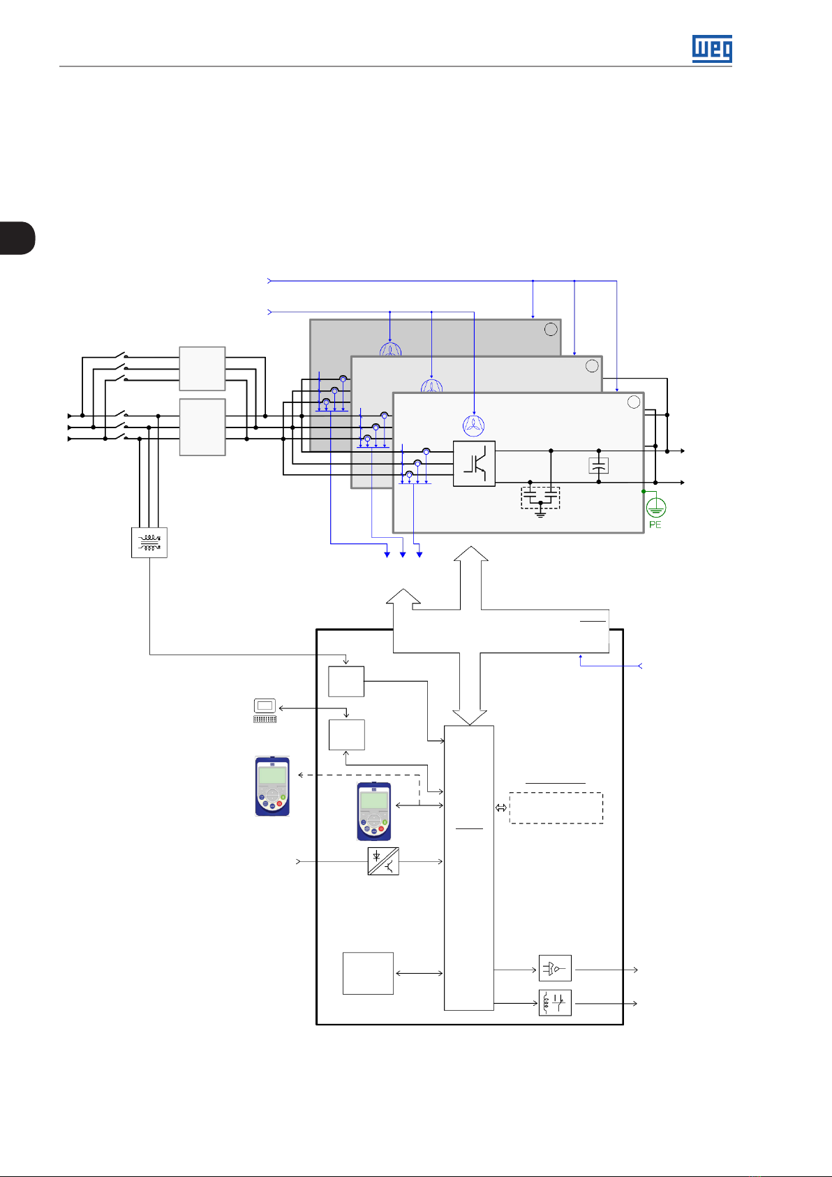
The CFW-11W G2 RB regenerative frequency converter line is water cooled, being smaller than the other converters.
The UP11s, UP11Ws and UC11RB G2 are fed through an external +24 Vdc power supply. Figure 2.1 on page 2-4 and
Figure 2.3 on page 2-6 respectively show the general diagrams of the air-cooled and water-cooled converters,
considering the configuration with three UP11s connected in parallel.
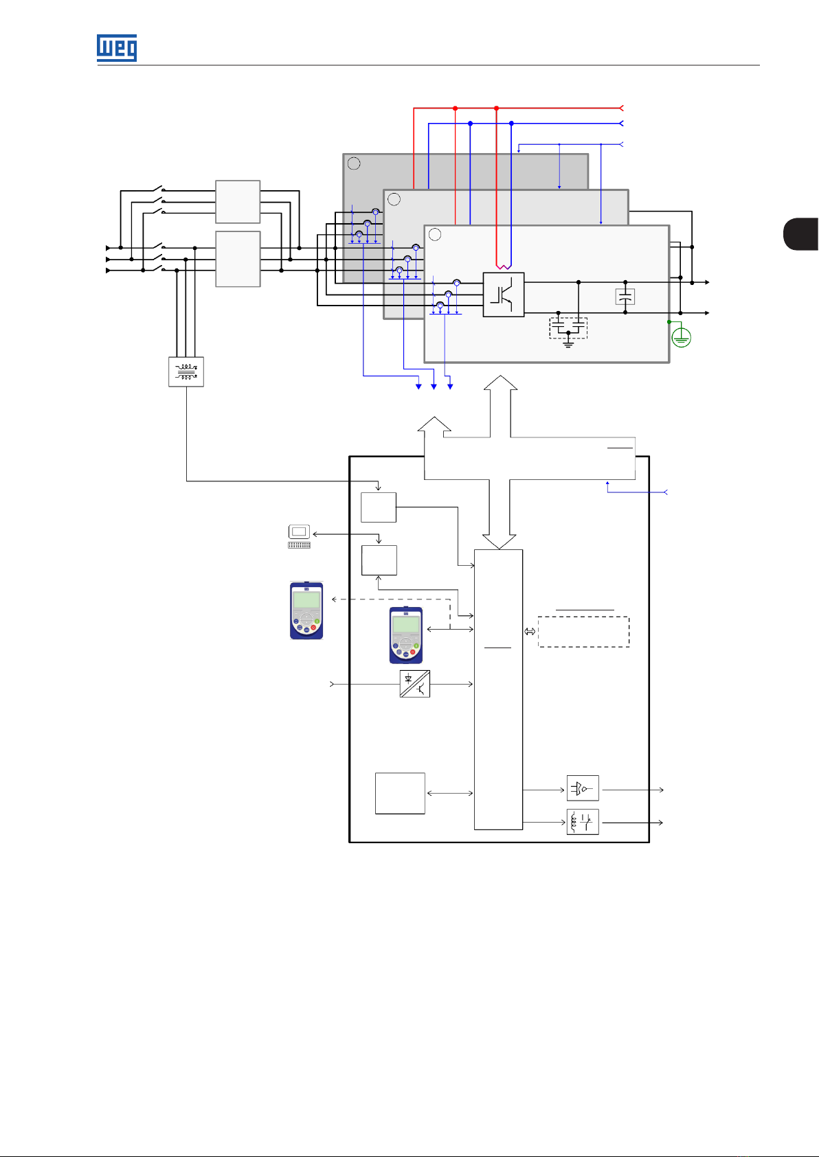
The UC11RB G2 control unit controls the power units. The control unit contains the control rack of the CFW-11
2
line and the ICUP board. This board sends signals to all UP11 G2 or UP11W G2 (PWM, control signals, etc.), and
receives signals from them (current, voltage feedback, etc.).
24 Vdc external power
supply - electronics UP11
220 Vac external power
supply - fans
UP11
3
Pre-
charge
Input
Mains
filter
Synchronism
transformer
PC
SuperDrive G2
software
Power
control
CSR
USB
Feedbacks:
- voltage
- current
IGBT fans
Inverter with
IG B Ts
PMW
Power supplies for electronics
and interfaces between power
and control
UP11
Capacitor
ICUP
2
bank
UP11
1
DC+
DC-
PERFI filter
24 Vdc external
power supply electronics UC11
DC
Output
2-4 | CFW-11MW G2 RB
Accessories
I/O expansion
HMI
(remote)
Digital
inputs (DI1
to DI6)
memory
module
Figure 2.1: General diagram of the CFW11M G2 RB converter
HMI
Flash
CC11
Control
board
with
RISC
32-bit
CPU
(Slot 1 – white)
Analog outputs
(AO1 and AO2)
Digital outputs
DO1 (RL1) to
DO3 (RL3)
Page 12
General Information
Water cooling system
24 Vdc external power
UP11W3
supply - electronics UP11
Pre-
charge
Input
Mains
filter
Synchronism
transformer
PC
SuperDrive G2
software
CSR
USB
UP11W
2
Feedbacks:
- voltage
- current
UP11W
1
Inverter with
IG B Ts
RFI filter
PMW
Power supplies for electronics and
interfaces between power and control
Capacitor
bank
ICUP
DC+
DC
Output
DC-
PE
24 Vdc external
power supply electronics UC11
2
Accessories
I/O expansion
HMI
(remote)
Digital
inputs (DI1
to DI6)
Memory
Module
Figure 2.2: General diagram of the CFW11W G2 RB converter
HMI
Flash
CC11
Control
board
with
RISC
32-bit
CPU
(Slot 1 – white)
Analog outputs
(AO1 and AO2)
Digital outputs
DO1 (RL1) to
DO3 (RL3)
CFW-11MW G2 RB | 2-5
Page 13
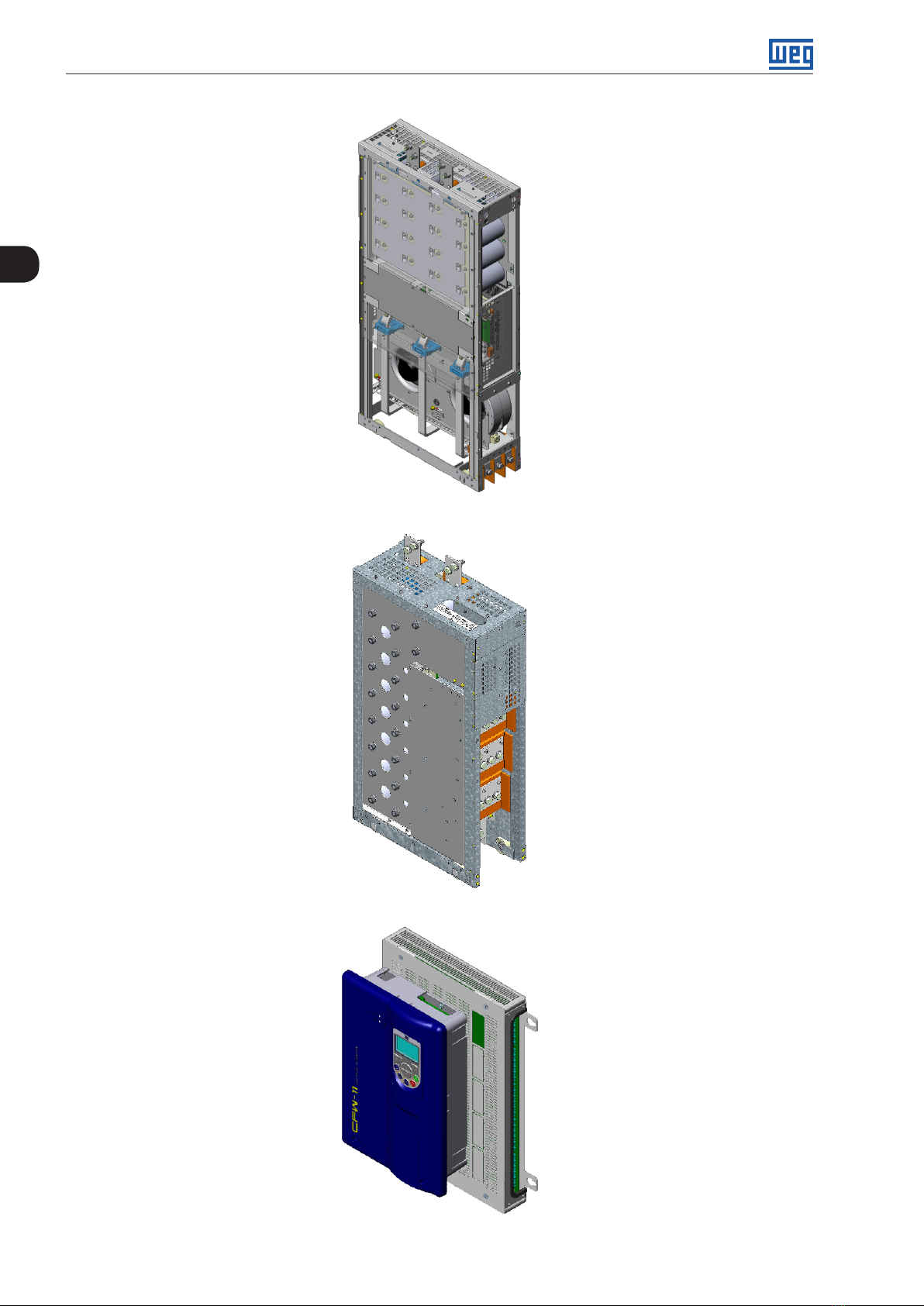
General Information
2
Figure 2.3: Air-cooled Power Unit (UP11)
2-6 | CFW-11MW G2 RB
Figure 2.4: Water-cooled Power Unit (UP11W)
Figure 2.5: Control Unit (UC11RB G2)
Page 14
NOTE!
To assemble the complete drive, several additional items are necessary, such as fuses on the DC
power supply of each UP11 or UP11W power unit, external pre-charge circuit and input filters.
NOTE!
It is not necessary to include a current transformer (CT) in the drive for short-circuit protection at the
output against the ground, since each UP11 and UP11W has its own internal protection.
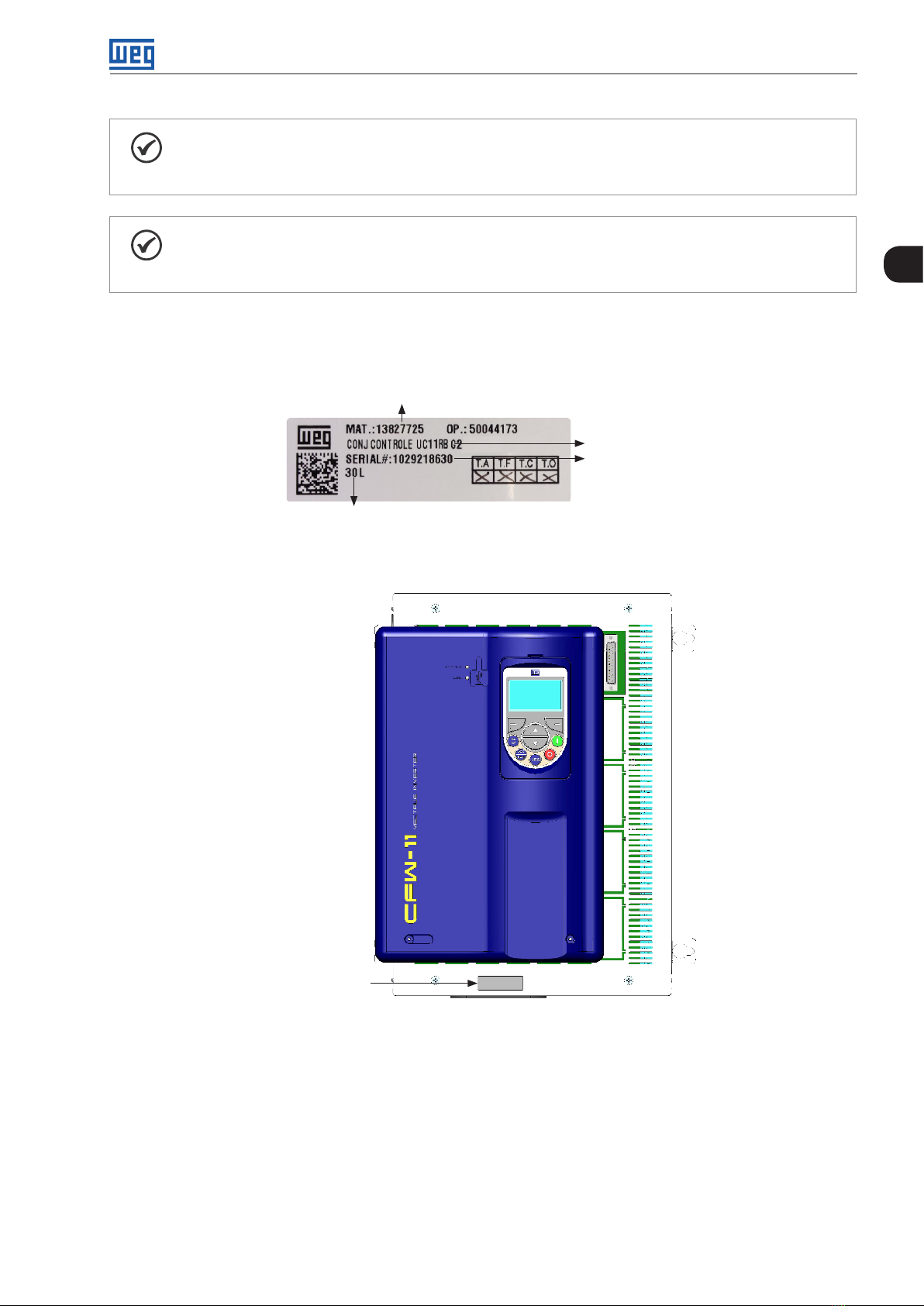
2.4 UC11RB G2 IDENTIFICATION LABEL
The UC11RB G2 identification label is located on the control rack.
WEG material
General Information
2
UC11 model
Serial number
Manufacturing date
(30 corresponds to the
week and L to the year)
Figure 2.6: UC11RB G2 identification label
Identification label
Figure 2.7: Identification label location
CFW-11MW G2 RB | 2-7
Page 15

General Information
2.5 UP11 G2 AND UP11W G2 IDENTIFICATION LABEL
The identification label is located on the front of the UP11 G2 and UP11W G2.
Model of the UP11
2
WEG part number
Inverter net weight
Rated input data (voltage, rated
currents for operation under normal
duty and heavy duty, frequency)
Current specifications for
operation under normal duty (ND)
Current specifications for
operation under heavy duty (HD)
MOD.: UP11-01 G2 48 H
MAT.: 13353741 SERIAL#: 1234567890
OP. : 12 34 567 8 MA X. TA: 45 ºC (113 °F )
PESO/WEIGHT: 171 kg (377 lb)
LINK DC
574-970 V DC
A (ND)
60 s/3s
A (HD)
60 s/3s
A (HD)
60s/3s
A (HD)
60s/3s
Hz 50/60 Hz 0-200 Hz
570 A
437 A
758 -1025 VDC
505 A
390 A
FABRICADO NO BRASIL
HECHO EN BR ASIL
MADE IN BR AZIL
OUTPUT
SALIDA
SAÍDA
0-0,71*VDC
VAC 3~
496 A
546 A / 744 A
380 A
570 A / 760 A
0-0,71*VDC
VAC 3~
439 A
483 A / 695 A
340 A
510 A / 680 A
to the week and H to the year)
Serial number
Maximum ambient temperature
around the inverter
Rated output data (voltage, number of
phases, rated currents for operation
under normal duty (ND) and heavy duty
(HD), overload currents for 1 min and 3
s and frequency band).
89 41717 070572
Figure 2.8: UP11 G2 and UP11W G2 identification label
Manufacturing date (48 corresponds
2-8 | CFW-11MW G2 RB
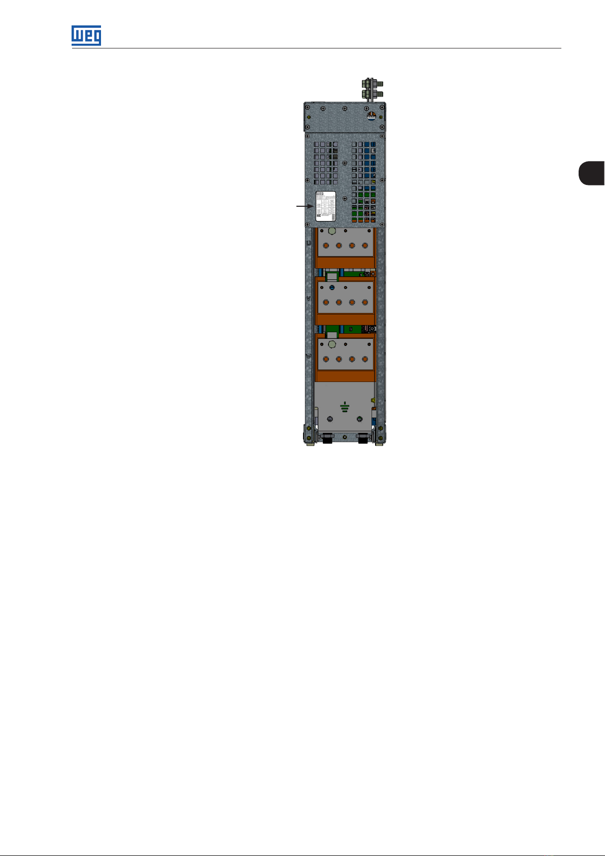
Identification
label
Figure 2.9: Identification label location on the UP11 G2
Page 16
Identification
label
General Information
2
Figure 2.10: Identification label location on the UP11W G2
CFW-11MW G2 RB | 2-9
Page 17
General Information
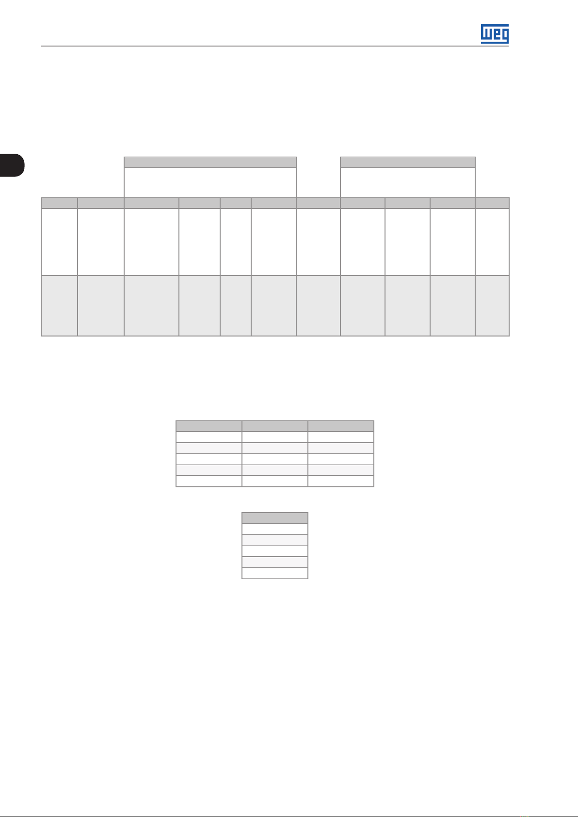
2.6 HOW TO SPECIFY THE CONVERTER MODEL (SMART CODE)
In order to specify the model of the CFW-11M G2 RB or CFW-11W G2 RB, replace the corresponding fields in the
smart code with the desired rated supply voltage and rated output current for operation under normal duty (ND),
as shown in the example of Table 2.1 on page 2-10.
Table 2.1: Smart code
2
Example BR CF W11M G 2 634 T 4 O _ _ _ _ _ _ Z
Field
denomination
Possible
options
Market
identification
(sets the
language of
the manual
and factory
settings)
2 characters CFW11WG2 =
See the list of models in Chapter 8 TECHNICAL
DATA on page 8-1, which also contains the
WEG Series
11 Generation
2 Modular
Converter
WEG Series 11
Generation 2
Water-Cooled
Modular
Converter
Converter Model Optional Items
See Chapter 7 OPTIONAL ITEMS AND
technical data of the inverters
Rated
current for
use under
normal
duty (ND)
Number
of
phases
T =
threephase
Rated
voltage
4 =
380...480 V
5 =
500...600 V
6 =
660...690 V
Optional
items
O = product
with
optional
item
ACCESSORIES on page 7-1 for
further details on the optional items
Braking Special
RB =
regenerative braking
hardware
Blank =
standard
H1 = special
hardware #1
Special
software
Blank =
standard
S1 = special
sof tware #1
Final
coding
indicator
digit
E.g.: CFW11MG21205T4ORBZ corresponds to a three-phase 1205 A CFW-11M G2 RB converter, with an input
voltage of 380 V to 480 V. The options for the rated current of the CFW-11M G2 RB and CFW-11W G2 RB
converters under normal overload (ND) are respectively found in Table 2.2 on page 2-10 and Table 2.3 on page
2-10, according to the rated input voltage of the converter.
Table 2.2: Rated currents under normal duty (ND) for the CFW-11M G2 RB
380-480 V 500-600 V 660 -690 V
0634 = 634 A 0496 = 496 A 0439 = 439 A
1205 = 1205 A 0942 = 942 A 0834 = 834 A
1807 = 1807 A 1414 = 1414 A 1251 = 1251 A
2409 = 2409 A 1885 = 1885 A 1668 = 1668 A
3012 = 3012 A 2356 = 2356 A 2085 = 2085 A
Table 2.3: Rated currents under normal duty (ND) for the CFW-11W G2 RB
500-690 V
0780 = 780 A
1482 = 1482 A
2223 = 2223 A
2964 = 2964 A
3705 = 3705 A
2-10 | CFW-11MW G2 RB
Page 18
2.7 RECEIVING AND STORAGE
The UP11 and UP11W G2 power units are supplied in a wooden box.
The UC11RB G2 control units are supplied in a cardboard box.
The package bears a copy of the identification label affixed to the converter.
To open the package:
1. Remove the front cover of the package.
2. Remove the styrofoam protection.
Check if:
1. The identification labels correspond to the models purchased.
2. Damages during transportation.
Report any problems immediately to the carrier.
General Information
2
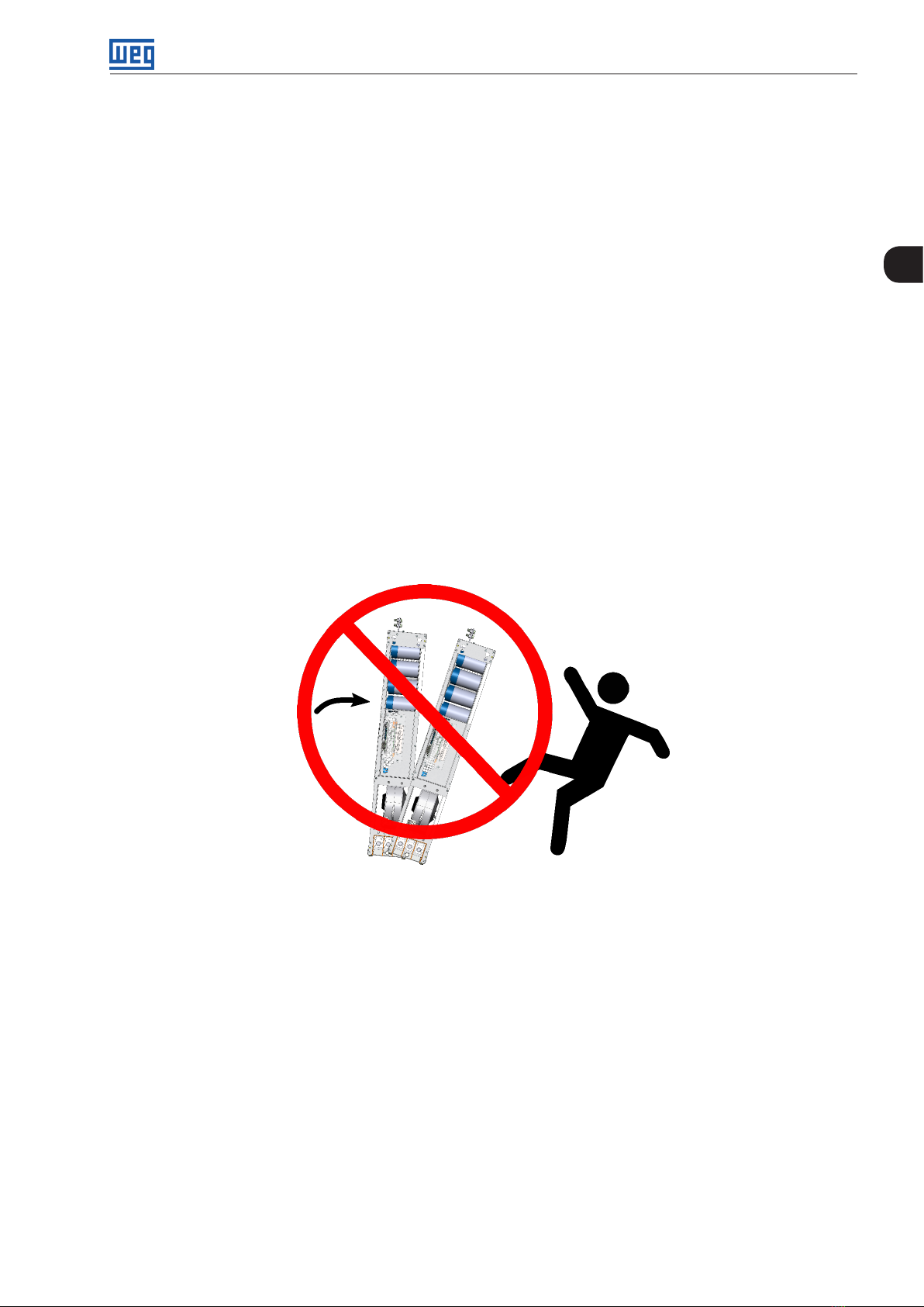
If the products are not immediately installed, store them in a clean and dry place (temperature between -25 ºC
and 60 ºC), with a cover to prevent the ingress of dust.
Figure 2.11: Do not tilt the power units
CFW-11MW G2 RB | 2-11
Page 19

General Information
2
2-12 | CFW-11MW G2 RB
Page 20

Installation and Connection
3 INSTALLATION AND CONNECTION
This chapter describes the procedures for the electrical and mechanical installation of the CFW-11M and
CFW-11W G2 RB. The directions and suggestions must be observed to ensure the safety of people and
equipment and the proper operation of the inverter.
3.1 AIR-COOLED UP11 G2 MECHANICAL INSTALLATION
The power units must be installed in the drive panel appropriately, allowing easy extraction and reinstallation in
case of maintenance. The mounting must be such to avoid damage during the panel transportation.
3.1.1 Environmental Conditions
Avoid:
Direct exposure to sunlight, rain, excessive moisture or marine environment.
Inflammable or corrosive liquids or gases.
Excessive vibration.
Dust, metal particles or oil suspended in the air.
Permissible environment conditions for operation:
Ambient temperature: 0 °C to 45 °C (32 ºF to 113 ºF) - rated conditions (measured around the inverter). From
45 ºC to 55 ºC (113 ºF to 131 ºF) - 2 % of current derating for each Celsius degree above 45 ºC (113 ºF).
Maximum altitude: up to 1000 m (3.300 ft) – rated conditions.
From 1000 m to 4000 m (3.300 ft to 13.200 ft) – 1 % of current derating for each 100 m (330 ft) above 1000 m
(3.300 ft) of altitude.
From 2000 m to 4000 m (6.600 ft to 13.200 ft) - maximum voltage (480 V for models 380...480 V and 690 V for
models 500...690 V) derating of 1.1 % for each 100 m (330 ft) above 2000 m (6.600 ft).
3
Maximum altitude of 4000 m (13.200 ft).
Air relative humidity: 5 % to 95 % non-condensing.
Pollution degree: 2 (according to EN50178 and UL508C), with non-conductive pollution. Condensation must
not cause conduction of the accumulated residues.
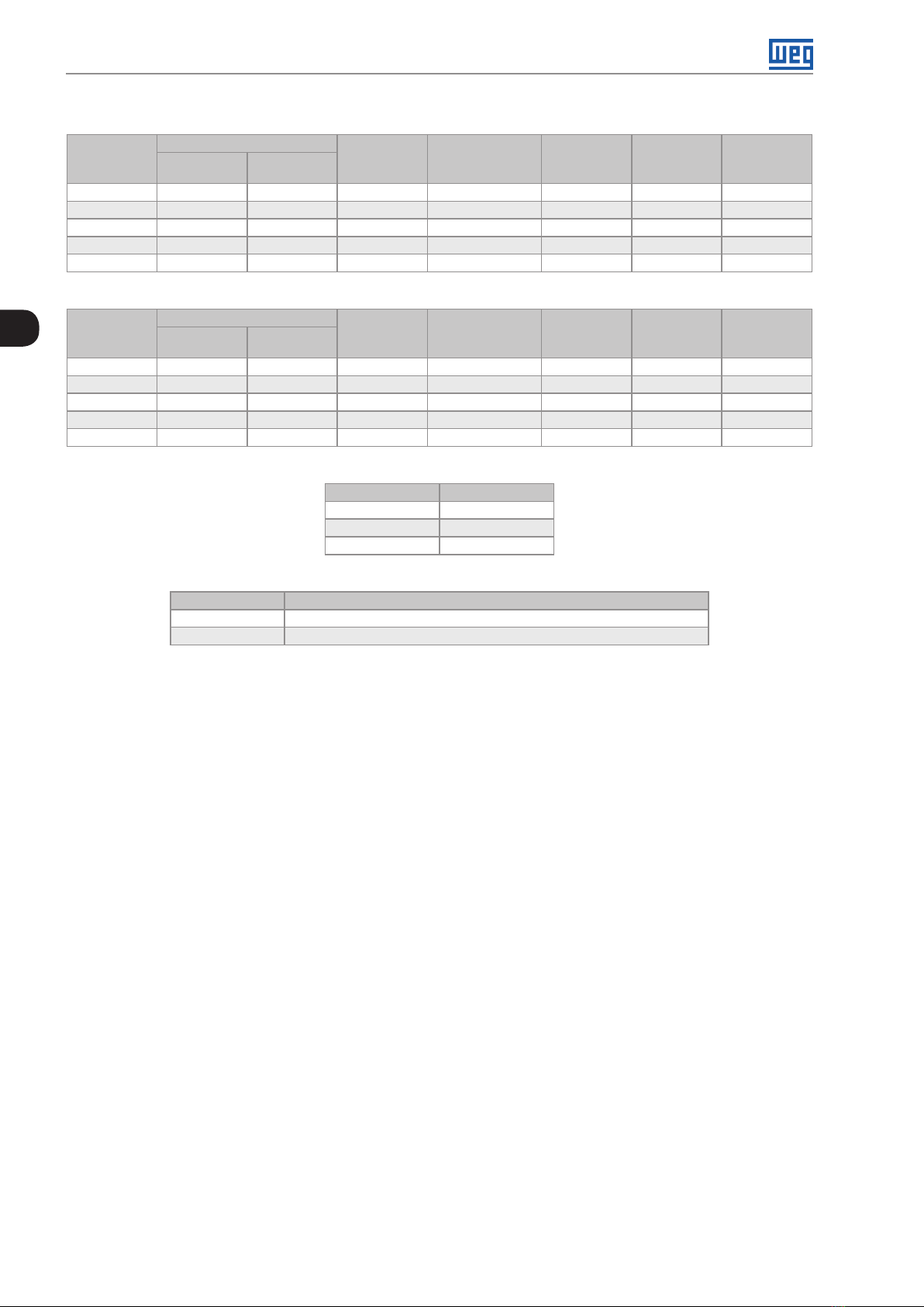
3.1.2 Part List
For the panel mounting of the CFW11M G2 RB, it is necessary: UC11RB G2 control set, UP11 G2 power units,
synchronism transformers and cable set to connect the UC11RB G2 to the UP11 G2. Table 3.1 on page 3-1,
Table 3.2 on page 3-2 and Table 3.3 on page 3-2 contain the Part List of the CFW-11M G2 converter.
Table 3.1: Part List - Drives CFW-11M G2 RB 380 - 480 V
Qty UP11-02
G2
1 634 515 1 1 1 - 2 1205 979 1 1 2 - 3 1807 14 6 8 1 1 - 1 2
4 2409 1957 1 1 2 1 1
5 3012 2446 1 1 - 3 2
Rated Current [A]
ND HD
Qty UC11RB
G2
Qty
Synchronization
Transformers Set
Qty Cable
Set 2.5 m
Qty Cable
Set 3.0 m
Qty Cable
Set 3.6 m
CFW-11MW G2 RB | 3-1
Page 21
Installation and Connection
Table 3.2: Part List - Drives CFW-11M G2 RB 500 - 600 V
Qty UP11-01
G2
1 496 380 1 1 1 - 2 942 722 1 1 2 - 3 1414 1083 1 1 - 1 2
4 1885 1444 1 1 2 1 1
5 2356 1805 1 1 - 3 2
3
Qty UP11-01
G2
1 439 340 1 1 1 - 2 834 646 1 1 2 - 3 1251 969 1 1 - 1 2
4 1668 1292 1 1 2 1 1
5 2085 1615 1 1 - 3 2
Rated Current [A]
ND HD
Table 3.3: Part List - Drives CFW-11M G2 RB 660 - 690 V
Rated Current [A]
ND HD
Qty UC11RB
G2
Qty UC11RB
G2
Table 3.4: Cable set items
WEG Item Cable Set
13555095 2.5 m Cables
13555150 3.0 m Cables
135 55151 3.6 m Cables
Qty
Synchronization
Transformers Set
Qty
Synchronization
Transformers Set
Qty Cable
Set 2.5 m
Qty Cable
Set 2.5 m
Qty Cable
Set 3.0 m
Qty Cable
Set 3.0 m
Qty Cable
Set 3.6 m
Qty Cable
Set 3.6 m
Table 3.5: Synchronous transformer set items
WEG Item Synchronism Transformer Set
14267304 Synchronism transformer set: input voltage 380 - 480 V
14267307 Synchronism transformer set: input voltage 500 - 690 V
The panel builder must provide the other parts of the drive. Among those parts are the power busbars, pre-charge
circuit, panel fans, protection fuses and input filters.
3-2 | CFW-11MW G2 RB
Page 22
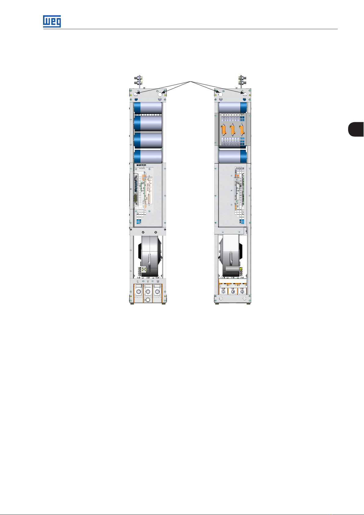
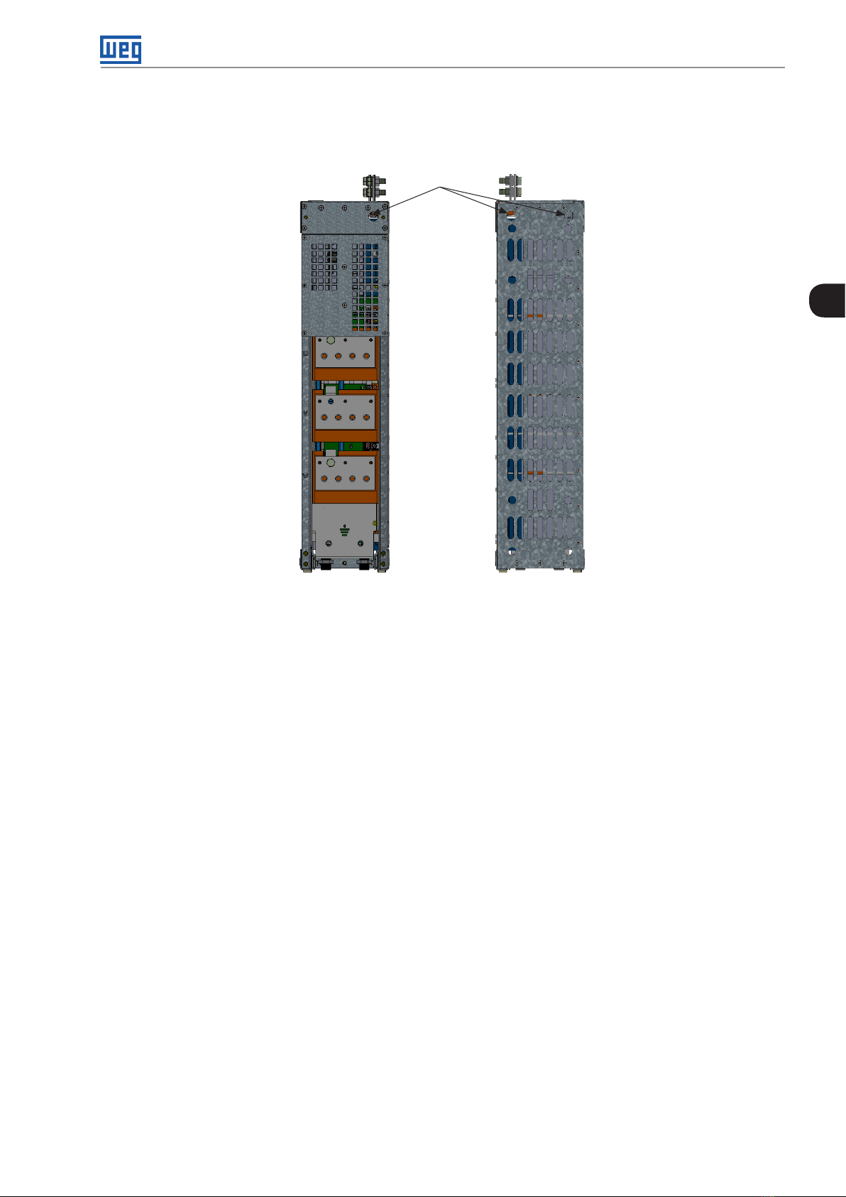
3.1.3 Lifting
Figure 3.1 on page 3-3 shows the position of the lifting lugs.
Lifting lugs
Installation and Connection
3
Front view Back view
Figure 3.1: UP11 G2 lifting lugs
CFW-11MW G2 RB | 3-3
Page 23
Installation and Connection
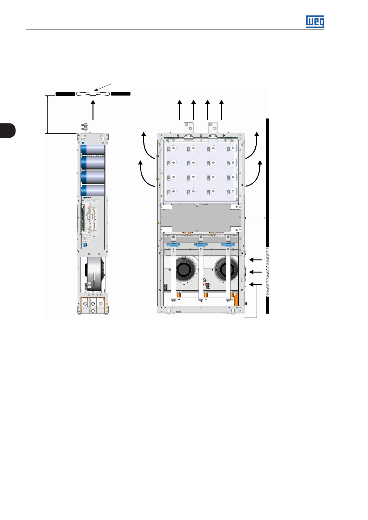
3.1.4 Panel Ventilation
The efficiency of the panel ventilation depends on the equipment installed inside the panel, such as fans, air inlets
and filters. The internal fan of the UP11 G2 is not enough to cool the entire panel.
Panel fan (when required)
Air outlet
Air outlet
[10.0] 250
3
[6.0]
150
Air inlet
Figure 3.2: Clearances for ventilation in mm [in]
The total air flow of the power unit fans is 1150 m3/h (320 l/s; 677 CFM).
3.1.5 Panel Mounting of the UP11 G2
To install the UP11 G2 in panels, the following fastening hardware is necessary:
Rack 2 G2 allows the mounting of 1 or 2 modules side by side in 600 mm wide panels.
Ventilation
openings on the
front surface of
the panel
Rack 3 G2 allows the mounting of 1, 2 or 3 modules side by side in 800 mm wide panels.
3-4 | CFW-11MW G2 RB
Page 24
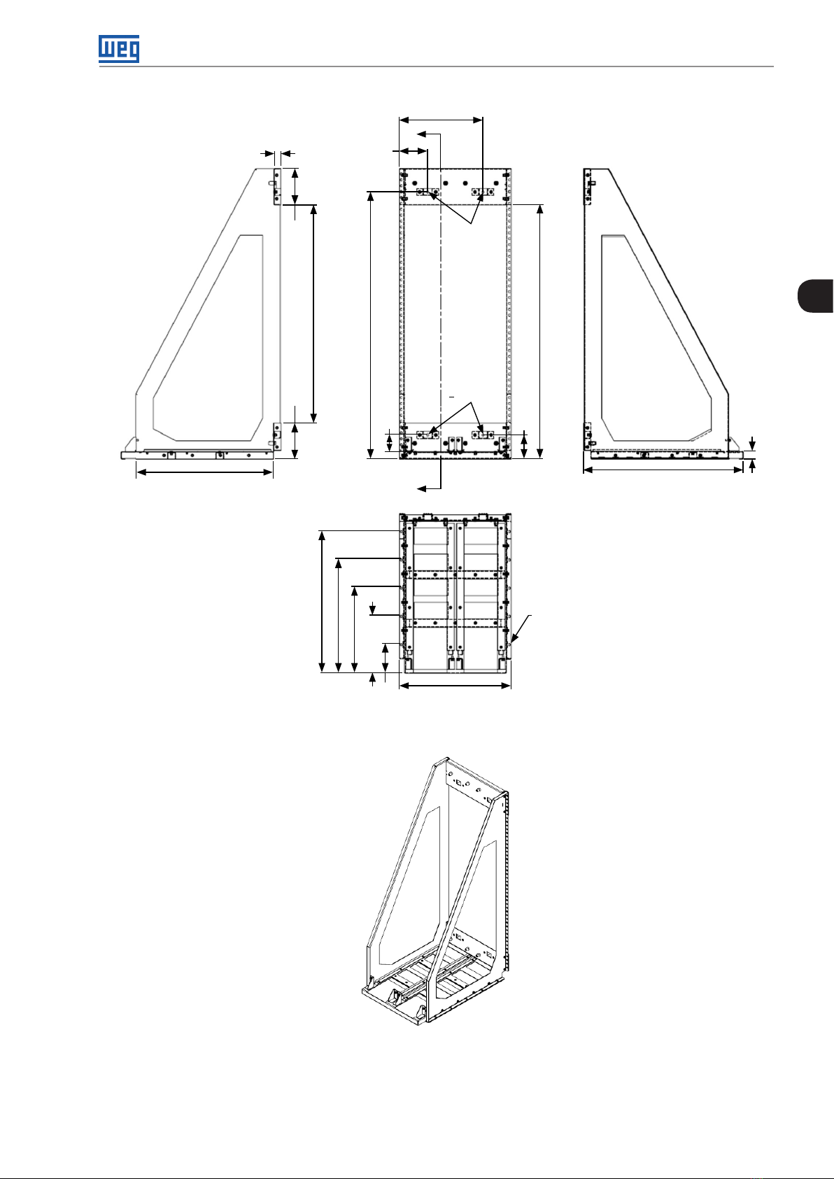
30.1 [1.19]
15 5 . 2 [ 6.11]
199.7 [4.71]
926.7 [36.48]
Installation and Connection
354.7 [13.96]
A
Ø9.2 [0.36]
3
1134.5 [44.67]
1079.3 [42.49]
582 [22.91]
SECTION A-A
A
474.4 [18 . 6 8]
Ø9.2 [0.36]
102.5 [4.04]
Ø9.2 [0.36]
32.6 [1. 28]
670.8 [26.72]
152.6 [6.01]
69.9 [2.75]
602.5 [23.72]
482.5 [19]
38 2.5 [14.27]
242.5 [9.55]
122.5 [4.82]
Figure 3.3: Dimensions of Rack 2 G2 in mm [in]
CFW-11MW G2 RB | 3-5
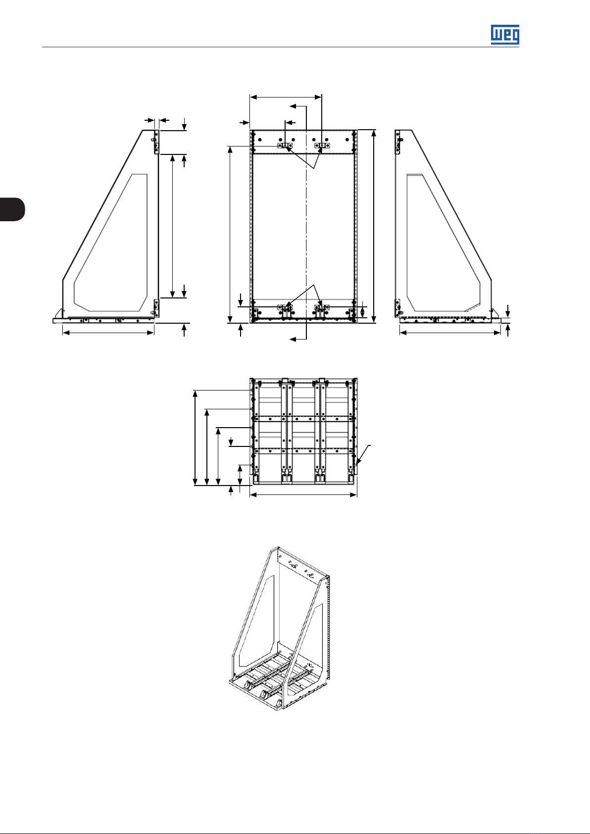
Page 25
Installation and Connection
459.6 [18 .1]
30.1 [1.19]
15 5 . 2 [ 6.11]152.6 [6.01]
A
224.6
[8.84]
Ø9.2 [0.36]
3
926.7 [36.48]
1134.5 [44.67]
102.5 [4.04]
582 [22.93] 678.8 [26.72]
SECTION A-A
602.5 [23.72]
482.5 [19]
36 2.5 [14.27]
242.5 [9.55]
122.5 [4.82]
Ø9.2 [0.36]
A
684.7 [26.96]
1234.5 [48.6]
68.3 [2.69]
Ø9.2 [0.36]
32.6 [1. 28]
3-6 | CFW-11MW G2 RB
Figure 3.4: Dimensions of Rack 3 G2 in mm [in]
Page 26
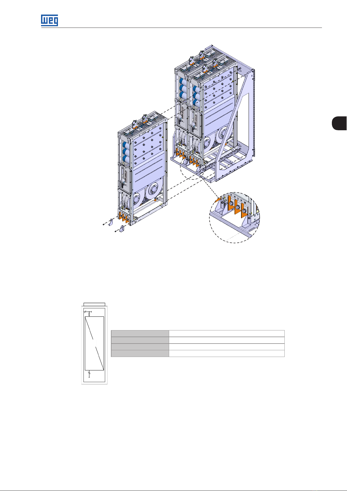
Installation and Connection
3
Figure 3.5: Insertion of the UP11 G2 power modules into the Rack 3 G2
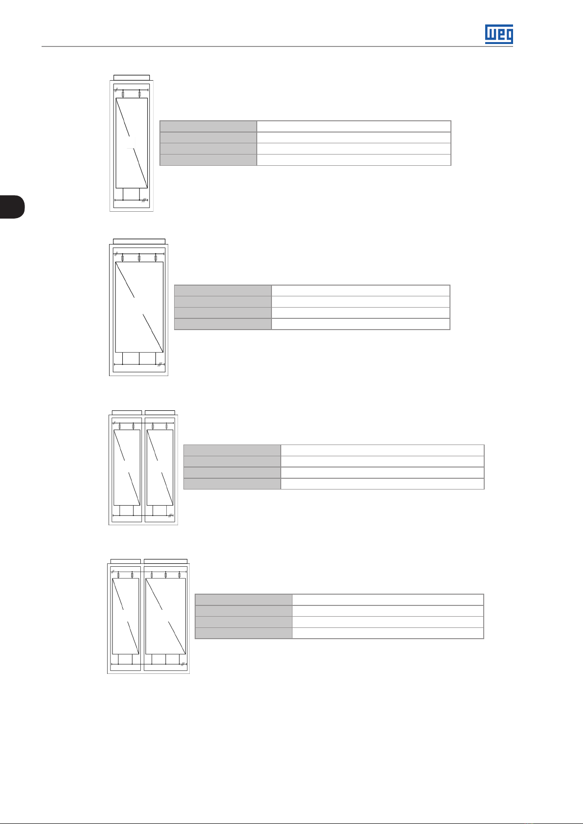
3.1.6 Panel
According to the quantity of UP11 G2 of the drive, minimum dimensions are necessary for the panels. Table 3.6
on page 3-10, Table 3.7 on page 3-10, Table 3.8 on page 3-10, Table 3.10 on page 3-19 and Table 3.11 on page
3-19 contain the minimum dimensions of the panel according to the quantity of UP11 G2 used.
Panel Width At least 600 mm
1
Panel Height At least 2000 mm
Panel Depth At least 800 mm
Weight Capacity 118 kg
Figure 3.6: Panel data for a drive with 1 UP11 G2
CFW-11MW G2 RB | 3-7
Page 27
Installation and Connection
Panel Width At least 600 mm
2
Panel Height At least 2000 mm
Panel Depth At least 800 mm
Weight Capacity 212 kg
3
Figure 3.7: Panel data for a drive with 2 UP11 G2
Panel Width At least 800 mm
3
Panel Height At least 2000 mm
Panel Depth At least 800 mm
Weight Capacity 310 kg
Column A Column B
2
Column A Column B
2 3
2
Figure 3.8: Panel data for a drive with 3 UP11 G2
Panel Width At least 600 mm (Column A) + 600 mm (Column B)
Panel Height At least 2000 mm
Panel Depth At least 800 mm
Weight Capacity 212 kg (Column A) + 212 kg (Column B)
Figure 3.9: Panel data for a drive with 4 UP11 G2
Panel Width At least 600 mm (Column A) + 800 mm (Column B)
Panel Height At least 2000 mm
Panel Depth At least 800 mm
Weight Capacity 212 kg (Column A) + 310 kg (Column B)
3-8 | CFW-11MW G2 RB
Figure 3.10: Panel data for a drive with 5 UP11 G2
Page 28
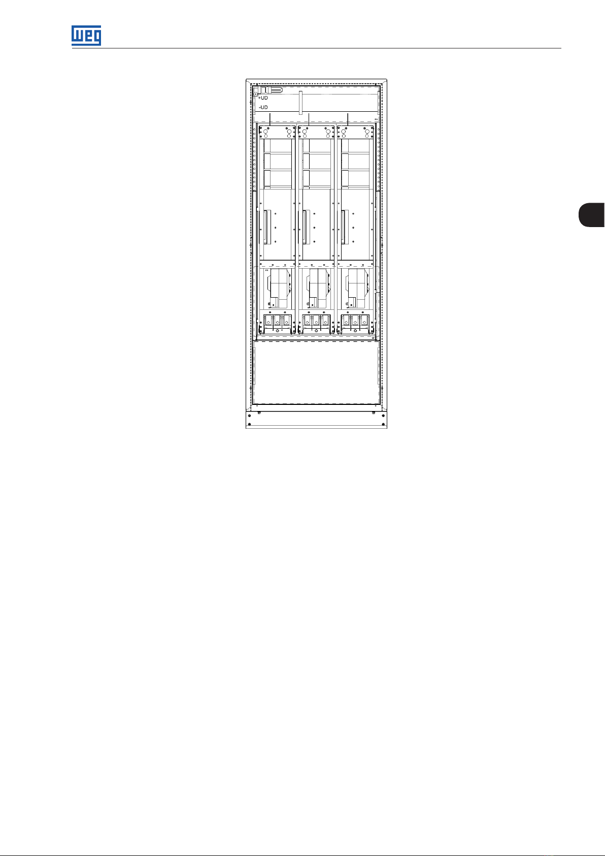
Installation and Connection
3
Figure 3.11: Column with 3 UP11 G2 installed
3.2 WATER-COOLED UP11W G2 MECHANICAL INSTALLATION
The power units must be installed in the drive panel appropriately, allowing easy extraction and reinstallation in
case of maintenance. The mounting must be such to avoid damage during the panel transportation.
3.2.1 Environmental Conditions
Avoid:
Direct exposure to sunlight, rain and high humidity.
Inflammable or corrosive liquids or gases.
Dust, metal particles or oil suspended in the air.
Environment conditions permitted for operation:
Ambient temperature: 0 °C to 45 °C (32 ºF to 113 ºF) - rated conditions (measured around the inverter). From
45 ºC to 55 ºC (113 ºF to 131 ºF) - 0.5 % of current derating for each Celsius degree above 45 ºC (113 ºF).
Coolant input temperature: 0 ºC to 45 ºC (32 ºF to 113 ºF) according to the coolant used. From 45 ºC to 55 ºC
(113 ºF to 131 ºF) - 1 % of current derating for each Celsius degree above 45 ºC (113 ºF).
Coolant flow: 20 l/min.
Maximum altitude: up to 1000 m (3.300 ft) – rated conditions.
From 1000 m to 4000 m (3.300 ft to 13.200 ft) – 1 % of current derating for each 100 m (330 ft) above 1000 m
(3.300 ft) of altitude.
CFW-11MW G2 RB | 3-9
Page 29
Installation and Connection
From 2000 m to 4000 m (6.600 ft to 13.200 ft) - maximum voltage (690 V for models 500...690 V) derating of
1.1 % for each 100 m (330 ft) above 2000 m (6.600 ft).
Maximum altitude of 4000 m (13.200 ft).
Air relative humidity: 5 % to 95 % non-condensing.
Pollution degree: 2 (according to EN50178 and UL508C), with non-conductive pollution. Condensation must
not cause conduction of the accumulated residues.
3
3.2.2 Part List
For the panel mounting of the CFW11W G2 RB, it is necessary: control set, UP11W G2 power units and cable
sets to connect the UC11RB G2 to the UP11W G2. Table 3.1 on page 3-1 contains the part list of the CFW11W
G2 inverter.
Table 3.6: Part List - CFW-11W G2 500 - 600 V Drives
Qty
UP 11W- 01 G2
1 780 640 1 1 1 - 2 148 2 1216 1 1 2 - 3 2223 1824 1 1 - 1 2
4 2964 2432 1 1 2 1 1
5 3705 3040 1 1 - 3 2
Rated Current [A]
ND HD
WEG Item Synchronism Transformer Set
14267304 Synchronism transformer set: input voltage 380 - 480 V
14267307 Synchronism transformer set: input voltage 500 - 690 V
Qty UC11 G2
Table 3.7: Cable set items
WEG Item Cable Set
13555095 2.5 m Cables
13555150 3.0 m Cables
135 55151 3.6 m Cables
Table 3.8: Synchronous transformer set items
Qty
Synchronization
Transformers Set
Qty Cable
Set 2.5 m
Qty Cable
Set 3.0 m
Qty Cable
Set 3.6 m
The panel builder must provide the other parts of the drive. Among those parts are the power busbars, pre-charge
circuit, panel internal cooling, protection fuses and input filters.
3-10 | CFW-11MW G2 RB
Page 30
3.2.3 Lifting
Figure 3.1 on page 3-3 shows the position of the lifting lugs.
Lifting lugs
Installation and Connection
3
Front view Back view
Figure 3.12: UP11W G2 lifting lugs
CFW-11MW G2 RB | 3-11
Page 31

Installation and Connection
3.2.4 Panel Mounting of the UP11W G2
To install the UP11W G2 in panels, the following mounting accessories are necessary:
Rack 2 G2 allows the mounting of 1 or 2 modules side by side in 600 mm wide panels.
Rack 3 G2 allows the mounting of 1, 2 or 3 modules side by side in 800 mm wide panels.
[14.161]
[1.18 5 ]
30.1
[4.909]
124.7
359.7
H
3
[6 .11]
155. 2
[0.362]
∅ 9.2
501.7
[19.752]
784.5
[30.886]
[0.362]
∅ 9.2
884.5
[34.823]
[19.047]
483.8
SECTION H-H
32.6
227. 6
[8.9 61]
478.5
[18.837]
358.5
[14 .113]
12 7. 5
[50.2]
H
238.5
[9.388]
118 . 5
[4.664]
[19.0 83]
484.7
95
[3.73 6]
[21.8 0 3]
553.8
[0.362]
∅ 9.2
[1.283]
3-12 | CFW-11MW G2 RB
Figure 3.13: Dimensions of Rack 2 G2 in mm [in]
Page 32

[19]
483.8
SECTION A-A
[1.2]
30.1
Installation and Connection
[18 .1]
459.7
[8.8]
224.7
[6 .1]
155. 2
[19.8]
501.7
[30.9]
784.5
[9]
227.7
[5]
12 7. 5
A
[0.4]
∅ 9.2
[36]
914.1
[0.4]
3
∅ 9.2
[1.3]
[3.7]
94.9
A
[21.8]
553.8
32.6
[18.8]
478.5
[14 .1]
358.5
[9.4]
238.5
[4.7]
118 . 5
[27]
684.7
[0.4]
∅ 9.2
Figure 3.14: Dimensions of Rack 3 G2 in mm [in]
CFW-11MW G2 RB | 3-13
Page 33

Installation and Connection
3
Figure 3.15: Insertion of the UP11W power modules into the Rack 3 G2
3.2.5 Panel
The minimum panel dimensions are subject to the quantity of UP11Ws G2 of the drive. Table 3.6 on page 3-10,
Table 3.7 on page 3-10, Table 3.8 on page 3-10, Table 3.10 on page 3-19 and Table 3.11 on page 3-19 contain
the minimum dimensions of the panel according to the quantity of UP11W G2 used.
3-14 | CFW-11MW G2 RB
Page 34

Installation and Connection
Panel Width At least 600 mm
1
Panel Height At least 2000 mm
Panel Depth At least 600 mm
Weight Capacity 89 kg
3
Figure 3.16: Panel data for a drive with 1 UP11W G2
Panel Width At least 600 mm
2
Panel Height At least 2000 mm
Panel Depth At least 600 mm
Weight Capacity 156 kg
3
Column A Column B
2
2
Figure 3.17: Panel data for a drive with 2 UP11W G2
Panel Width At least 800 mm
Panel Height At least 2000 mm
Panel Depth At least 600 mm
Weight Capacity 227 kg
Figure 3.18: Panel data for a drive with 3 UP11W G2
Panel Width At least 600 mm (Column A) + 600 mm (Column B)
Panel Height At least 2000 mm
Panel Depth At least 600 mm
Weight Capacity 156 kg (Column A) + 156 kg (Column B)
Figure 3.19: Panel data for a drive with 4 UP11W G2
CFW-11MW G2 RB | 3-15
Page 35

Installation and Connection
Column A Column B
2 3
Panel Width At least 600 mm (Column A) + 800 mm (Column B)
Panel Height At least 2000 mm
Panel Depth At least 600 mm
Weight Capacity 156 kg (Column A) + 227 kg (Column B)
3
Figure 3.20: Panel data for a drive with 5 UP11W G2
3-16 | CFW-11MW G2 RB
Figure 3.21: Column with 3 UP11W G2 installed
Page 36

3.2.6 Cooling System
Figure 3.22 on page 3-17 shows the details of the coolant inlet and outlet.
Installation and Connection
Coolant inlet
Coolant outlet
Figure 3.22: Detail of the coolant inlet and outlet
Table 3.9 on page 3-17 contains detailed specifications of the UP11W G2 cooling system.
Table 3.9: Cooling system specifications
Coolant Inlet Temperature
Fluid Temperature Increase
Coolant Flow 20 l/min
Maximum Flow Allowed 30 l/min
Maximum System Pressure in Relation
to the Atmosphere
Load Loss on the Inver ter Heatsink
Coolant Inlet and Outlet Fit tings Used on
the Inverter
(1) Considering the 20 l/min flow and the composition of 90 % of water and 10 % of glycol in the coolant.
(1)
From 0 ºC to 45 ºC (32 ºF to 113 ºF) according to the coolant used; see Table 3.12
on page 3-19. From 45 ºC to 55 ºC (113 ºF to 131 ºF) with output current derating
6 °C (46 ºF)
6 bar (600 kPa)
(1)
0.84 bar (84 kPa)
Stainless steel bulkhead fitting for 16 mm tube, M24X1.5 thread and 24° taper
(DIN 3861/ISO 8434-1). According to Figure 3.23 on page 3-17
3
M24X1. 5 thread
Tube gauge 16 mm
internal taper of 24°
(DIN 3861 / ISO 8434-1)
Figure 3.23: Details of the hydraulic connection on the product
CFW-11MW G2 RB | 3-17
Page 37

Installation and Connection
ATTENTION!
It is recommended to use stainless steel hydraulic connections in the application cooling system.
Figure 3.14 on page 3-13 shows a simplified diagram of a closed cooling system for the UP11W G2.
Degassiing Valve
Over Pressure Valve
Diaphragm
accumulator
3
Temperature transmitter
Pressure transmitter
Flow transmitter
TT PT FT
Flow indicators
Bypass valve
Heat
ex-changer
FI
UP11W
Figure 3.24: Simplified example of a closed cooling system
UP11W UP 11W
FI FI FI FI
UP11W UP11W
The bypass valve is necessary for the temperature control and protection against condensation. The diaphragm
accumulator ensures a quite constant pressure in the cooling system even when great variations occur in the
coolant temperature. The pump provides the continuous coolant flow; it is recommended that such pump be
made of stainless steel. The acceptable differential pressure in the cooling circuit in relation to the atmosphere
must not exceed 6 bar. That must be guaranteed by the over pressure valve.
ATTENTION!
The hoses that connect the cooling system to the UP11W G2 must not conduct electricity.
ATTENTION!
The acceptable differential pressure in the cooling circuit in relation to the atmosphere must not
exceed 6 bar.
ATTENTION!
The cooling circuits of the UP11W G2 must not be connected in series in the cooling system circuit.
NOTE!
WEG RSW cooling system can be used for cooling the CFW11W G2 RB. For further information,
refer to the RSW User's Manual.
3-18 | CFW-11MW G2 RB
Page 38
Installation and Connection
The water used in the coolant must meet the specifications of Table 3.10 on page 3-19. The coolant must not
contain any organic sediments or active chemical agents. The coolant is composed of demineralized water,
corrosion inhibitor and ethylene glycol.
Table 3.10: Water specification
Characteristic Unit Value
pH 6 - 8
Hardness °dH < 10
Conductivity µS/cm < 10
Chlorine mg/l < 10
Iron mg/l < 0.1
Maximum particle
size
ATTENTION!
Do not use sea or tap water in the coolant.
The specifications of the inverter output current informed in Chapter 8 TECHNICAL DATA on page 8-1 are for a
coolant temperature between 10 and 45 °C (50 ºF to 113 ºF), and the composition according to Table 3.11 on
page 3-19.
µm < 300
3
Table 3.11: Coolant composition for temperature from 10 to 45 °C (50 ºF to 113 ºF)
Component Proportion
Demineralized water 88.5 %
Ethylene glycol 10 %
Inhibitor CorteC VpCI-649 1. 5 %
For the inverter operation at temperatures below 10 °C (50 ºF), the concentration of ethylene glycol in the coolant
must be increased. The increase of the percentage of ethylene glycol reduces the coolant specific heat and the
system heat exchange capacity. Therefore, if the inverter operates with a quantity of ethylene glycol above the
specification of Table 3.11 on page 3-19 and coolant temperature of 45 °C (113 ºF), the output current must be
derated. As the ethylene glycol concentration is normally increased to reduce the coolant freezing point, the coolant
temperature reduction can compensate the current derating. Table 3.12 on page 3-19 shows the maximum
percentage of the output current as a function of the ethylene glycol concentration and the coolant temperature.
Table 3.12: Maximum percentage of the output current as a function of the ethylene glycol concentration and the coolant temperature
Glycol Concentration
10 % 20 % 30 % 40 % 50 %
37 °C 100 % 100 % 100 % 100 % 100 %
39 °C 100 % 100 % 100 % 100 % 98 %
41 °C 100 % 100 % 100% 98 % 96 %
43 °C 100 % 100 % 98 % 96 % 94 %
45 °C 100 % 98 % 96 % 94 % 92 %
47 °C 98 % 96 % 94 % 92 % 90 %
49 °C 96 % 94 % 92 % 90 % 88 %
51 °C 94 % 92 % 90 % 88 % 86 %
Coolant Temperature
53 °C 92 % 90 % 88 % 86 % 84 %
55 °C 90 % 88 % 86 % 84 % 82 %
ATTENTION!
To prevent corrosion, always add 1 % of the inhibitor CorteC VpCI-649 to the coolant.
Condensation may occur when the incoming water temperature is significantly lower than the ambient temperature.
The water temperature to avoid condensation varies according to the air relative humidity and ambient temperature.
The temperature at which the water vapor contained in the air turns into liquid as small water drops is known as
"dew point".
CFW-11MW G2 RB | 3-19
Page 39

Installation and Connection
Table 3.13 on page 3-20 shows the dew point in relation to the air relative humidity and to the ambient temperature
for an atmospheric pressure of 1 atm. If the water temperature is lower than the indicated value, condensation
may occur.
Table 3.13: Dew point in relation to the air relative humidity and ambient temperature (°C)
Air Relative Humidity
5 % 10 % 20 % 30 % 40 % 50 % 60 % 70 % 80 % 90 %
10°C <0 <0 <0 <0 <0 0 .1 2.6 4.8 6.7 8.4
20°C <0 <0 <0 1.9 6 9.3 12 14.4 16.4 18.3
25°C <0 <0 0.5 6.2 10.5 13.8 16.7 19 .1 21.3 23.2
30°C <0 <0 4.6 10.5 14.9 18.4 21.4 23.9 26.2 28.2
35°C <0 <0 8.7 14.8 19.4 23 2 6.1 28.7 31 3 3 .1
3
Ambient
Temperature
40°C <0 2.6 12.7 19.1 23.8 2 7. 6 30.7 33.5 35.9 38
45°C <0 6.3 16.8 23.4 28.2 3 2.1 35.4 38.2 40.7 43
ATTENTION!
The water temperature must always be higher or equal to the dew point.
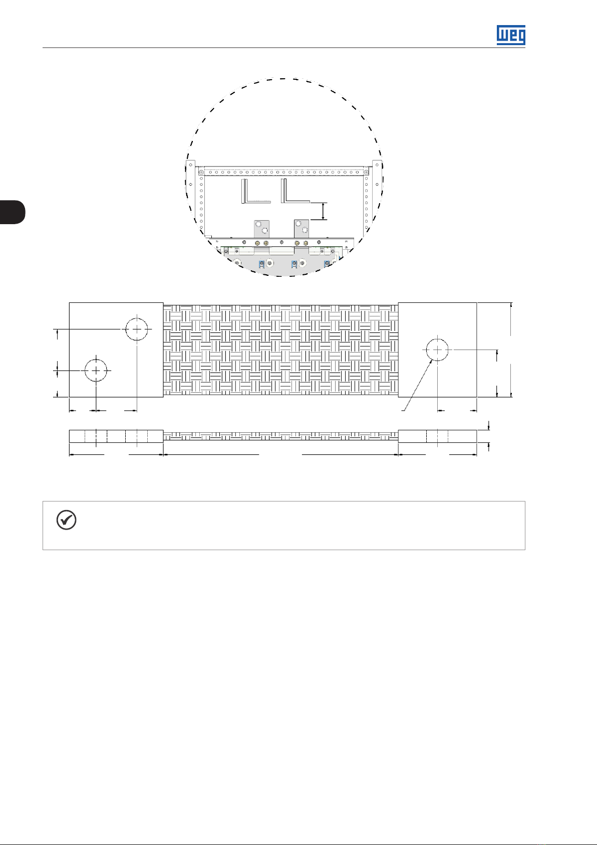
3.3 UC11 MECHANICAL INSTALLATION
Mounting of the UC11RB G2 on the panel door: control rack with flange mount and ICUP board shield mounted
inside the door. The control rack is mounted with four screws M3 (recommended torque: 0.5 N.m).
ICUP
3-20 | CFW-11MW G2 RB
Figure 3.25: Example of mounting of the control rack in the panel
Page 40

Installation and Connection
ø 5.2 (4X)
(0.20)
(5.64)
143.3
286.5
Figure 3.26: Mounting of the control rack and necessary slots in mm (in)
[11. 2]
283.6
190
(7. 4 8)
R8 (4X)
(11.28)
186.5
(7.34)
7 (0.27)
(0.32)
93.3
(3.67)
2 (0.08)
11
(0.43)
290
(11.42)
7 (0.27)
3
[1.6]
41.5
292
[11. 5]
[0.2]
R4 (4x)
Figure 3.27: Mounting of the base of the ICUP module in mm (in)
The shield of the ICUP board is mounted with four screws M6 (recommended torque: 8.5 N.m).
CFW-11MW G2 RB | 3-21
Page 41

Installation and Connection
3.4 ELECTRICAL INSTALLATION
DANGER!
The following information is intended to be a guide for proper installation. Comply with applicable
local regulations for electrical installations.
DANGER!
Make sure the power supply is disconnected before starting the connections.
3
ATTENTION!
The CFW-11M G2 RB and CFW-11W G2 RB can be connected to circuits with short-circuit capacity
of up to 100000 symmetric Arms (maximum 480 V/690 V).
ATTENTION!
The short-circuit protection of the converter does not provide short-circuit protection for the feeder
circuit. The short-circuit protection of the feeder circuit must be provided in accordance with the
applicable local regulations.
3.4.1 Pre-Charge
The resistors of the pre-charge circuit must be sized according to the following criteria:
Maximum voltage.
Maximum energy.
Power overload capacity of the resistors during the pre-charge period (energy dissipation capacity).
Table 3.14: Sizing of the pre-charge
Peak current during the pre-charge (A) 0.82 x (V
Energy stored in the capacitor bank (J)
Pre-charge duration
(1) This calculation considers the use of the same number of power units in the regenerative frequency
converter and in the inverter connected to the motor. When the CFW11M RB G2 or CFW11W RB G2 feeds
several other inverters, you must consult WEG for the correct sizing of the pre-charge resistor.
(1)
(1)
UP11- 01 G2 N.0.012.V
UP11- 02 G 2 N.0.024.V
UP11W-01 G2 N.0.014.V
UP11- 01 G2 0.1.N.R
UP11- 02 G 2 0.2.N.R
UP11W-01 G2 0 .11.N.R
Being R the ohmic value of the resistor used on each phase and N the number of regenerative power units.
Table 3.15 on page 3-22 contains the maximum ohmic value that can be applied to the pre-charge resistors.
/R)
line
2
line
2
line
2
line
3-22 | CFW-11MW G2 RB
Table 3.15: Maximum pre-charge resistor value for the CFW11M G2 RB
Nº. of UP11s
1 5.0 Ω 11.0 Ω 7.5 Ω
2 2.5 Ω 3.8 Ω 5.0 Ω
3 1.5 Ω 2.5 Ω 3.5 Ω
4 1.2 Ω 2.0 Ω 2.5 Ω
5 1.2 Ω 1.8 Ω 2.0 Ω
Power Supply
380-480 V
Power Supply
500-600 V
Power Supply
660 -690 V
Page 42

Installation and Connection
Table 3.16: Maximum pre-charge resistor value for the CFW11W G2 RB
N° of UP11Ws 500-690 V
1 5.5 Ω
2 3.0 Ω
3 2.0 Ω
4 1.4 Ω
5 1.2 Ω
E.g.:
In a drive consisting of three regenerative power units plus three output power units whose line voltage at the
converter input is 690 Vrms (UP11-01 G2), the values obtained will be as follows:
3
Energy stored in the capacitor bank: 3 x 0.012 x 690
2
= 17x139.6 J.
Using three 3 Ω resistors (one per phase), each resistor must withstand 5,713.2 J.
The manufacturer of the resistor can inform the energy the component withstands.
The peak current during the pre-charge will be 188.6 A and the pre-charge duration will be 0.9 s.
KPCR
QPCR
R
Mains
K1
Filter
AC
Fuses
CFW11M G2 RB
or
CFW11W G2 RB
DC+ DC+
U U
DC
Fuses
V V
W W
DC- DC-
CF W 11M G 2
or
CF W 11W G 2
(*)
Synchronism
KSINC
QSINC
Motor
11
Stop
12
11
S
OFF
12
220 Vac
external
(*) If only one power unit is used at the output, it is not necessary to use fuses on the DC Link.
13 13
S
ON
14 14 21 21
A1
+RC +RC +RC +RC +RC
KA1
A2 A2 A2 A2 A2 A2
CC11 (D O1)
A1 A1 A1 A1 A1
15 13 43
KT1 KA2 KA2
16
18
18
KA1
44
XC12 2
XC123
KPCR
XC1: 21
KA2
22 22
KA2 K1KPCR
Figure 3.28: Example of a pre-charge activation circuit
14 44
KSINCKT1
CFW-11MW G2 RB | 3-23
Page 43

Installation and Connection
The power supply of the CFW-11M G2 RB or CFW-11W G2 RB regenerative frequency converters can be done via
contactor or motorized circuit breaker (represented by K1), observing that its command must be interlocked with
the command of the KPCR pre-charge contactor. Figure 3.28 on page 3-23 shows an example of a recommended
pre-charge circuit with the simplified power and control diagrams. The digital relay output DO1 of the CC11 board
must be configured with the "Pre-Charge OK" function (P0275 = 25). This relay must be used to command the
pre-charge contactor and the main contactor (motorized circuit breaker). In addition, the duration of the pre-charge
must be timed to protect the components of the auxiliary circuit (resistors, contactor). This function is performed
by a timing relay with on-delay, represented in Figure 3.28 on page 3-23 by RT1. The KSINC contactor ensures
that the synchronism circuit will only be powered after the completion of the pre-charge. The QPCR and QSINC
circuit breakers protect the pre-charge and synchronism circuits respectively.
3
3.4.2 Busbars
The panel busbars must be sized according to the converter output current and the drive input current. It is
recommended to use copper busbars. In case it is necessary to use aluminum busbars, it is necessary to clean
the contacts and use an anti-oxidant compound. If the compound is not used, any copper and aluminum joint
will undergo accelerated corrosion.
3.4.3 Fuses
Fuses must be installed at the input of each power unit, that is, each power unit must be individually proteced
with fuses at their input.
Ultrafast type fuses (UR) must be used at the input.
For UL conformity, use class J fuses at the converter power supply with current not above the values of
Table 3.17 on page 3-24.
Table 3.17: Recommended fuses
Recommended WEG Fuses
Model Current (A) Voltage (V) Duty
UP11- 02 G 2
UP11- 01 G2
UP11W-01 G2
634
515 HD
496
380 HD
439
340 HD
780
640 HD
380-480
500-600
660-690
500-690
ND
ND
ND
ND
In (A) Modelo
800 FNH3FEM-800Y-A
630 FNH3FEM-630Y-A
550 FNH3FEM-550Y-A
1000 FNH3FEM-1000Y-A
NH aR
Flush End
In Figure 3.29 on page 3-25 and Figure 3.30 on page 3-25 the fuse connection schemes are presented.
NOTE!
As noted in Figure 3.29 on page 3-25, when using one regenerative UP11 plus one output UP11,
no DC fuses are required.
3-24 | CFW-11MW G2 RB
Page 44

Mains
Filter protection
(circuit breaker
or fuses)
Filter
Installation and Connection
3
Mains
Filter protection
(circuit breaker
or fuses)
Filter
AC Fuses
Figure 3.29: Fuse connection diagram for one regenerative UP11 plus one output UP11
DC Fuses
AC Fuses
Figure 3.30: Fuse connection diagram for three regenerative UP11s plus three output UP11s
CFW-11MW G2 RB | 3-25
Page 45

Installation and Connection
3.4.4 General Wiring Diagram
Figure 3.31 on page 3-26 shows the general diagram for a converter with five Power Units (UP11). It shows
the connections between the Control Unit UC11RB and the PUs (Connectors DB25 XC40 and Fiber Optics),
power connections of the PUs (DC+, DC-, U, V, W and GND), and auxiliary power supply connections of the
cooling (220 V), of the UP11 (24 Vdc) and of the UC11 (24 Vdc). For a reduced number of UP11, connect them
in increasing order (1, 2, 3, etc.), leaving the last positions without connection. This diagram is valid for both
air-cooled UP11 G2 and water-cooled UP11W G2, except for the XC33 connector (fan connection), which does
not exist on the UP11W G2.
3
UC11 R B
ICUP
XC40AUH1...WL1
XC40XC40XC40XC40XC40
+UD
-UD
UP11
+UD -UD
U
V
UH...WLUH...WLUH...WLUH...WLUH...WL
XC33
11
222
220 Vac
XC6
111
222
24 Vcc
W
1
333
+UD
-UD
CC11
HMI
XC60
XC60
UP11
U
V
W
1
2
3
24 VCC
XC33
220 Vac
XC6
24 Vcc
1
+UD
Not
Digital
XC40C XC40B
used
XC33
XC5 XC67 XC9
inputs
1
220 Vac
UP11
24 Vcc
XC6
-UD
U
V
W
U
V
Filter
W
Mains
1
+UD
Not
BR
used
Error_BR
XC40D
UP11
-UD
U
V
W
XC33
220 Vac
XC6
1
1
2
24 Vcc
3
1
2
+UD
-UD
3-26 | CFW-11MW G2 RB
XC6
1
2
24 Vcc
U
V
W
1
3
UP11
UH5...WL5 UH4...WL4 UH3...WL3 UH2...WL2XC40E
XC33
1
2
220 Vac
Figure 3.31: General wiring diagram
Page 46

3.4.5 Power Connections
Mains
R
S T PE
Filter
U
V W PE
DC-
W W WV V VU U U
DC- DC-DC+ DC+ DC+
Installation and Connection
+
Output
-
DC
3
Fuses
Figure 3.32: Power and grounding connections
The DC+ and DC- connections of the UP11 G2 and UP11W G2 are fastened with 4 screws M12X35 (recommended
torque: 60 N.m); see Figure 3.33 on page 3-27 and Figure 3.34 on page 3-28.
DC- DC+
Figure 3.33: DC output terminals of the UP11 G2
CFW-11MW G2 RB | 3-27
Page 47

Installation and Connection
DC+ DC-
3
Figure 3.34: DC output terminals of the UP11W G2
DC+: Positive pole of the DC output voltage.
DC-: Negative pole of the DC output voltage.
On the UP11 G2 (air-cooled), the U, V and W connections are made through 3 screws M12X45 (recommended
torque: 60 N.m; see Figure 3.35 on page 3-29. The screw used to fasten the grounding cable of the UP11 G2
is M12X25 (recommended torque: 60 N.m).
3-28 | CFW-11MW G2 RB
Page 48

Installation and Connection
3
Figure 3.35: Input terminals U, V, W and ground on the UP11 G2
On the UP11W G2 (water-cooled), the U, V and W connections are made through 12 screws M12X25 (recommended
torque: 60 N.m; see Figure 3.36 on page 3-30). Two screws M12X25 (recommended torque: 60 N.m) are used
to fasten the grounding cable of the UP11W G2.
CFW-11MW G2 RB | 3-29
Page 49

Installation and Connection
U
V
3
W
Figure 3.36: Input terminals U, V, W and ground on the UP11W G2
U, V and W: connections to the filter.
: Grounding cable connection.
For a better current distribution between the UP11 G2 or UP11W, it is recommended that their output connections
be interconnected through a single paralleling busbar. The length of the cables between the UP11 G2 or UP11W
and the paralleling busbar must be as short as possible.
ATTENTION!
The output cables U, V and W of the UP11 G2 and UP11W G2 must have the same length.
ATTENTION!
If a busbar is used for parallelism of the power units, the filter cables must be distributed as evenly as
possible in the connection to the paralleling busbar, as shown in Figure 3.37 on page 3-31. Distance
"L" must be kept constant.
3-30 | CFW-11MW G2 RB
Page 50

Mains
R
S T PE
Filter
Installation and Connection
DC Output
DC+ DC+ DC+DC- DC- DC-
3
U
V
W
PE
U
Fuses
Paralleling
busbar
Figure 3.37: Recommended distribution for the filter cables
3.4.6 Input and Grounding Connections
ATTENTION!
Use proper lugs for the power and grounding connection cables.
ATTENTION!
Sensitive equipment, such as PLCs, temperature controllers and thermocouple cables, should be at
least 0.25 m away from the converter and from the cables connecting the input filter to the converter.
V V V
U U
W W W
L
L
L
L
L
L
L
L
L
L
L
L
Grounding
busbar
Phase U
Phase V
Phase W
DANGER!
Incorrect cable connection:
Check all the connections before energizing the converter.
In case of replacement of an existing converter by a CFW-11M G2 RB, check if all the installation
and wiring connected to it complies with the instructions of this manual.
DANGER!
Provide a disconnecting device for the converter power supply. This device must cut off the inverter
power supply whenever necessary (during maintenance, for instance).
CFW-11MW G2 RB | 3-31
Page 51

Installation and Connection
ATTENTION!
The supply voltage must not exceed the converter rated values (see Table 8.1 on page 8-2 and
Table 8.2 on page 8-3).
ATTENTION!
Capacitors for power factor correction must not be used at the input (U, V, W).
3
NOTE!
The gauges indicated in Table 3.18 on page 3-32 and Table 3.19 on page 3-33 are reference values
only. For the proper wiring sizing, consider the installation conditions and the maximum permissible
voltage drop.
Use two parallel cables with the gauge indicated in Table 3.18 on page 3-32 to interconnect connections U, V
and W of the UP11 with the paralleling busbar (filter output).
Table 3.18: Connection cables U, V and W
Model Current (A) Voltage (V) Duty
UP11- 02 G 2
UP11- 01 G2
UP11W-01 G2
634
515 HD (2X ) 185
496
380 HD (2X) 120
439
340 HD (2X) 120
780
640 HD (4X) 95
380-480
500-600
660-690
500-690
ND (2X) 300
ND (2X) 185
ND (2X) 150
ND (4X) 120
Minimum Cable Cross
Section (mm²)
ATTENTION!
Cables U, V and W of all phases of all UP11 G2 and UP11W G2 must have the same length to prevent
current unbalance.
The characteristics of the cable used to connect the converter to the filter, as well as its interconnection and
routing, are extremely important to avoid electromagnetic interference in other devices.
DANGER!
Do not share the grounding wiring with other devices that operate with high currents (e.g., high power
motors, welding machines, etc.).
ATTENTION!
The neutral conductor of the line that powers up the converter must be solidly grounded; however,
this conductor must not be used to ground the converter.
DANGER!
The converter must be connected to a protection grounding (PE).
Observe the following:
Connect the converter grounding points to a specific grounding rod or specific grounding point or
to the general grounding point (resistance ≤ 10 Ω).
Use a minimum cable gauge for connection to the ground as indicated in Table 3.19 on page 3-33.
if local standards require different gauges, they must be observed.
For compatibility with IEC 61800-5-1, use at least one 10 mm² copper cable to connect the converter
to the protective earth, since the leakage current is higher than 3.5 mA AC.
3-32 | CFW-11MW G2 RB
Page 52

Installation and Connection
Use the cables with the gauge indicated in Table 3.19 on page 3-33 to ground the UP11 power units.
Table 3.19: Grounding cables
Model Current (A) Voltage (V) Duty
UP11- 02 G 2
UP11- 01 G2
UP11W-01 G2
634
515 HD 185
496
380 HD 120
439
340 HD 120
780
640 HD (2X) 95
380-480
500-600
660-690
500-690
ND 300
ND 185
ND 150
ND (2X ) 120
Minimum Cable Cross
Section (mm²)
3.4.7 Terminals Recommended for Power Cables
Table 3.20: Terminals recommended for power cables
Cable Gauge
[mm²]
95 M12
120 M12
150 M12
185 M12
300 M12
Screw Manufacturer Lug Terminal, Code Crimping Tool, Code
Hollingsworth RM95 -12 Hydraulic tool H6-500 1
Tyc o XCT 95-12
Hollingsworth RM120 -12 Hydraulic tool H6-500 1
Burndy (FCI) YA 28L
Hollingsworth RM15 0 -12 Hydraulic tool H6-500 1
Burndy (FCI) YA 3 0 L
Hollingsworth RM18 5 -12 Hydraulic tool H6-500 1
Burndy (FCI) YA31L
Hollingsworth RM3 0 0-12 Hydraulic tool H6-500 1
Burndy (FCI) YA36L 2
UNIPRESS 6/120 +COF+CHARG
Item TE: 2107475-2
Tool without die: MY29-3 or Y644 or Y81
Tool+die: Y35 or Y750 / U29RT
Tool without die: Y644 or Y81
Tool+die: Y35 or Y750 / U30RT
Tool without die: Y644 or Y81
Tool+die: Y35 or Y750 / U31RT
Tool without die: Y644 or Y81
Tool+die: Y35 or Y750 / U36RT
3
Number of
Crimps
1
1
1
1
1
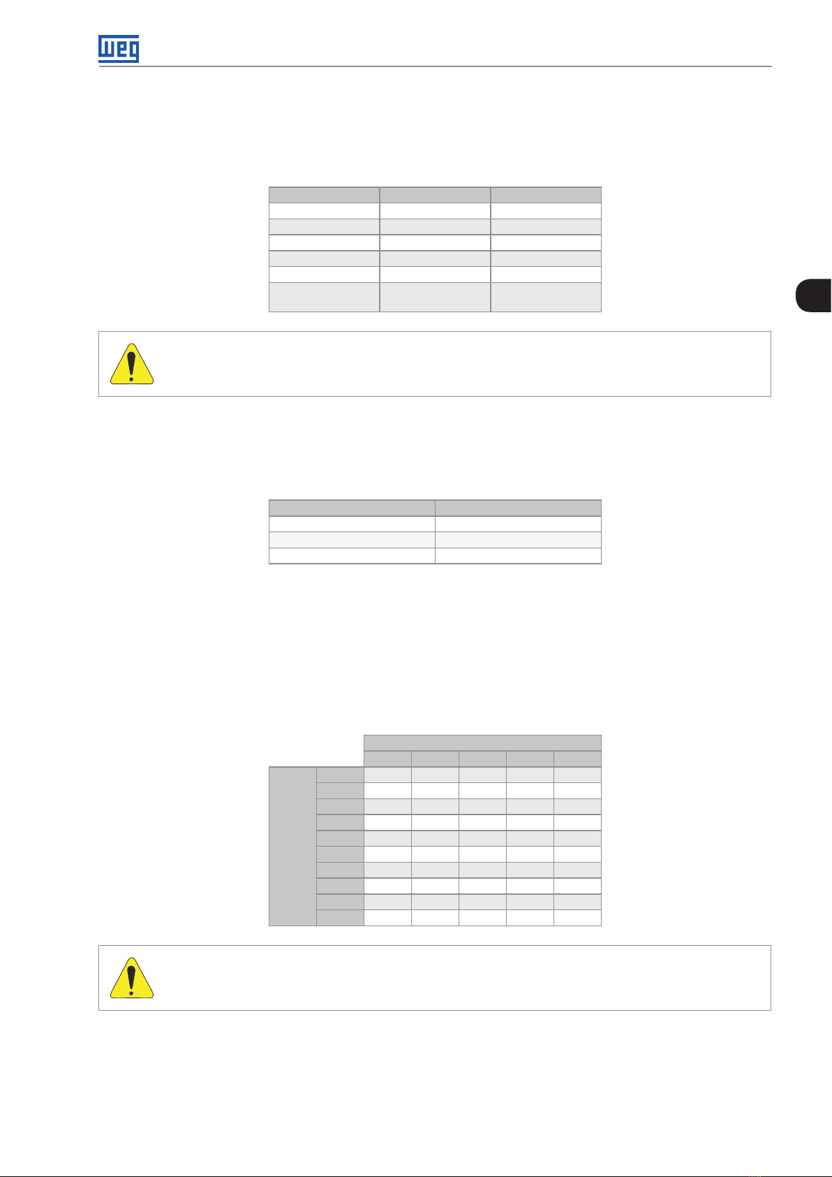
3.4.8 Output Connections
The DC link and each UP11 G2 or UP11W G2 can be interconnected with flexible braids as in the example of
Figure 3.38 on page 3-34, sized to withstand the DC link current, according to Table 8.1 on page 8-2. Figure
3.39 on page 3-34 shows an example of a flexible braid used by WEG.
CFW-11MW G2 RB | 3-33
Page 53
Installation and Connection
-UD +UD
3
Figure 3.38: Side view of the connections of the flexible braids and fuses
26
(1.02)
17
(0.67)
17
(0.67)26(1.02)
60
(2.36)
Braided wire gauge: AWG-40
Figure 3.39: Example of flexible braid - mm (in)
E
E
60
(2.36)
30
(1.18 )
Ø 14 (3x)
(0.55)
25
(0.98)
8±1
50
(1.97)
NOTE!
It is important that all the flexible braids have the same length (defined by dimension "E"), which will
depend on the panel construction.
3.4.9 Input Filters
3.4.9.1 Basic Definitions
For the operation of the regenerative frequency converter, it is necessary to use an input filter to eliminate the
circulation of high frequency currents generated by the switching of the regenerative frequency converter IGBTs
on the power grid. In this manual, input filters are the components connected between the power grid and the
regenerative frequency converter input.
3.4.9.2 How to Specify the Filter Model
WEG has input filters ready to be used with each of its regenerative frequency converters. To specify the model of
the input filter, enter the voltage and current values into the respective smart code fields for rated supply voltage
and rated input current, as in the example of Table 3.21 on page 3-35.
3-34 | CFW-11MW G2 RB
Page 54

Installation and Connection
Table 3.21: Smart code of the input filters
Example WLCL 0634 T 4
Field denomination WEG filter Filter rated current Number of phases Rated voltage
Available options
Check Table 3.22 on
page 3-35 and Table
3.23 on page 3-35
Table 3.22: Rated current of the input filters for the UP11 G2 (air cooling)
380-480 V 500-600 V 6 60 -690 V
0634 = 634 A 0496 = 496 A 0439 = 439 A
1205 = 1205 A 0942 = 942 A 0834 = 834 A
1807 = 1807 A 1414 = 1414 A 1251 = 1251 A
2409 = 2409 A 1885 = 1885 A 1668 = 1668 A
3012 = 3012 A 2356 = 2356 A 2085 = 2085 A
Table 3.23: Rated current of the input filters for the UP11W G2 (water cooling)
500-690 V
0780 = 780 A
1482 = 1482 A
2223 = 2223 A
2964 = 2964 A
3705 = 3705 A
T = three-phase
4 = 380...480 V
5 = 500...600 V
6 = 660...690 V
3
3.4.10 Synchronism
The CFW-11M G2 RB and the CFW-11W G2 RB monitor the line voltage (R, S and T) at the converter input by means
of a synchronism board and two transformers. The signals obtained are used in the control of the regenerative
frequency converter.
The synchronism circuit wiring diagram can be seen in Figure 3.28 on page 3-23. The KSINC contactor must
be closed together with the main contactor K1. It is recommended to use a circuit breaker (QSINC) to protect the
synchronism transformers.
T1
UP11 G 2
or
UP11W G2
U DC+
V
W
DC-
UC11RB G2
XC1:1
CSR11
Mains
K1
Filter
R
S
T
QSINC
KSINC
H1
H2
H1
H2
Figure 3.40: Synchronism wiring diagram
T2
X1
X2
X1
XC1:2
XC1:4
XC1:5
XC50
XC50
CC11
CFW-11MW G2 RB | 3-35
Page 55

Installation and Connection
H1
H2
X1
X2
3
Figure 3.41: Synchronism transformer
WEG supplies the synchronism transformers for panel mounting. Figure 3.42 on page 3-36 shows this mounting.
ATTENTION!
The shield of the synchronism transformers must be grounded.
Figure 3.42: Mounting example of the transformers
Table 3.14 on page 3-22 shows the specification of the synchronism transformer
Table 3.24: Synchronism transformer specifications
Input Voltage of CFW11-11M/W G2 RB 380 V - 480 V 500 V - 690 V
Rated voltage of the primary H1-H2 480 V 690 V
Transformer ratio NS/N
f (frequency) 50 Hz/60 Hz
S (power) 2.5 VA
Voltage tolerance ± 1 %
Steady state overvoltage 10 %
Insulation Class 1.1 k V
Class B
Insulation
Primary to secondary 3000 Vca / 1 min
Primary to shield 3000 Vca / 1 min
Primary to enclosure 3000 Vca / 1 min
Be in accordance wit UL508 standard as the insulation material and manufacturing
Keep the core with low saturation to mantain good linearity between the primary and secondary
Shielding between the primary and secondary: metallic ribbon
3-36 | CFW-11MW G2 RB
P
1/26 1/35
Page 56

Installation and Connection
Figure 3.43 on page 3-37, showing the CSR11 synchronism board, displays connector XC1, which receives the
signals coming from the synchronism transformers. Connector XC50, which makes the interconnection with the
CC11 RB control board, is also shown. Figure 3.44 on page 3-37 shows this connection and Figure 3.45 on page
3-38 shows the board assembly inside the UC11RB G2.
XC50
XC1
3
Figure 3.43: Synchronism board
ATTENTION!
Shielded cables must be used to connect the signals to connector XC1 of the synchronism board. It is
recommended to ground the cable shield according to Item 3.4.11.3 Conexões CC11 on page 3-46.
Figure 3.44: Connection of the CSR11 synchronism board
CFW-11MW G2 RB | 3-37
Page 57
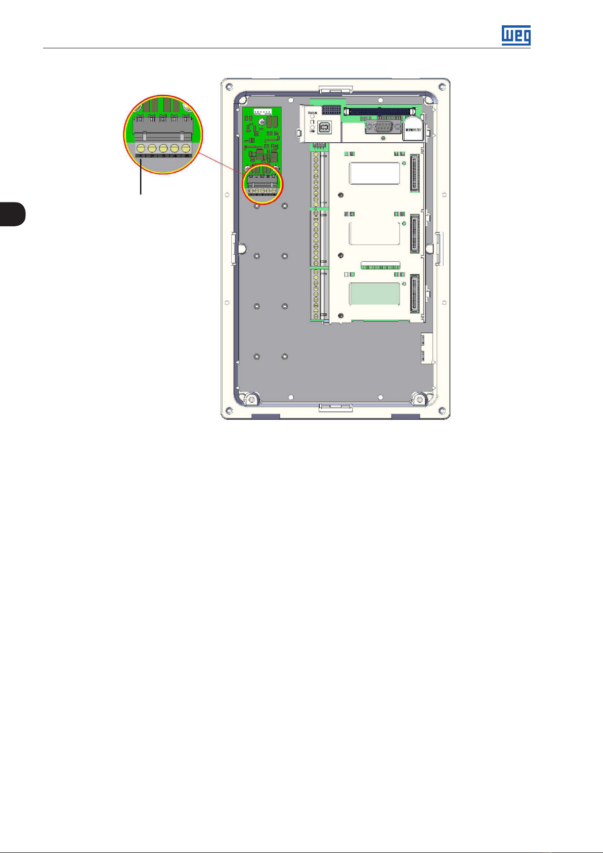
Installation and Connection
1
3
Figure 3.45: Assembly of the CSR11 board in the UC11RB G2
3-38 | CFW-11MW G2 RB
Page 58

3.4.11 Control Connections
3.4.11.1 UP11 G2 and UP11W G2 Connections
UP11 control
power supply
Connectors
fiber optic
Installation and Connection
3
Connector DB25
Figure 3.46: Control cable connection points on the UP11 G2
XC40: Connector DB25
Connectors fiber optic
UP11 control power supply
Figure 3.47: Control cable connection points on the UP11W G2
CFW-11MW G2 RB | 3-39
Page 59

Installation and Connection
XC6: Power supply
24 Vdc (UP11 G2
control)
Fiber optics connectors
(connections to the
ICUP board)
3
XC40: Connector
DB25 (connection
to the ICUP board)
Figure 3.48: Identification of the control connections
The electronics of the UP11 G2 and UP11W G2 is powered via connector XC6, located on the IUP board; it is
described in Table 3.25 on page 3-40.
Table 3.25: Description of connector XC6
XC6 Function Specifications
1 +24 Vdc Positive pole of the +24 Vdc power supply
2 NC Not connected
3 GND Reference of the +24 Vdc power supply
24 Vdc power supply(± 3 %)
Consumption: 750 mA per UP11 G2
3-40 | CFW-11MW G2 RB
Page 60

Installation and Connection
3
Power supply fans
Figure 3.49: Terminals to power the UP11 G2 fans
Table 3.26: Specification of the power supply of the fans
Volt ag e Frequency Current
220 Vac 50 / 60 Hz 4 Aac
3.4.11.2 UC11RB G2 Connections
DIM1 and DIM2 digital inputs located on the ICUP board (Table 3.27 on page 3-41) can be programmed via
parameters P0832 and P0833 respectively.
Table 3.27: Function of the signals on the connector XC5
Connector XC5 Factory Default Function Specifications
1 DIM1 DIM1 isolated digital input, programmable in (P0832).
Refer to the programming manual
2 DIM2 DIM2 isolated digital input, programmable in (P0833).
Refer to the programming manual
3 COM Common point of the digital inputs of the ICUP1 board
4 +24 V 24 Vdc power supply Isolated power supply 24 Vdc ± 8 %
5 GND_ 24 0 V reference for the 24 Vdc power supply
High level ≥ 18 V
Low level ≤ 3 V
Maximum input voltage: 30 V
Input current: 11 mA @ 24 Vdc
Capacity: 600 mA
Note 1: This power supply can be used to power DIM1 (ISOL) and
DIM2 (ISOL) digital inputs of the ICUP1 board
Note 2: This power supply is isolated from the 24 Vdc input used to
power ICUP1
Note 3: This is the same power supply available on the CC11 board
CFW-11MW G2 RB | 3-41
Page 61

Installation and Connection
Fiber optics connectors
(connection to UP11)
Connectors DB25
XC40A to XC40E
(connection to UP11)
3
XC5: DIM1 and DIM2
digital inputs
XC9: 24 Vdc
power supply
XC60: Connection
to control rack
XC67: No used DIP
switches
S1 and S2
Figure 3.50: ICUP board connection points
Fiber optics
connectors reserved
for WEG use
The control rack is powered via connector XC9, located on the ICUP board; it is described in Table 3.28 on page 3-42.
Table 3.28: Description of connector XC9
XC9 Function Specifications
1 +24 Vdc Positive pole of the +24 Vdc power supply
2 NC Not connected
3 GND Reference of the +24 Vdc power supply
24 Vdc power supply (± 3 %)
Consumption: 1.25 A
DIP switches S1 and S2, Figure 3.51 on page 3-42, have the function, respectively, to select the level of the inverter
alternating supply voltage and the number of UP11 G2 or UP11W G2 connected.
3-42 | CFW-11MW G2 RB
S2S1
Figure 3.51: Detail of DIP switches S1 and S2
Page 62

Installation and Connection
Table 3.29: DIP switch S1:1 - S1:3 configuration
S1:3 S1: 2 S1:1 Model
ON OFF ON UP11- 02 G 2 380 - 480 V
ON OFF OFF UP11- 01 G 2 500 - 690 V
OFF OFF OFF UP11W-01 G2 500 - 690 V
Table 3.30: DIP switch S1:4 configuration
S1:4 Operating Mode
OFF Normal
ON Reduced power
The operating mode with reduced power is detailed in Section 5.7 OPERATION WITH A REDUCED NUMBER OF
POWER UNITS on page 5-6.
Table 3.31: DIP switch S2 configuration
S2:4 S2:3 S2:2 S2:1
OFF OFF OFF OFF 1
OFF OFF OFF ON 2
OFF OFF ON ON 3
OFF ON ON ON 4
ON ON ON ON 5
Alternate Supply
Volt ag e
Number of
UP11 or UP11W
Connected
3
The UP11 G2 or UP11W G2 plus UC11RB G2 must be grounded according to the diagram shown in Figure 3.52
on page 3-44.
CFW-11MW G2 RB | 3-43
Page 63

Installation and Connection
ICUP
XC40
UH...WL
1
XC6
UP11
1
XC33
132
+UD
-UD
+UD -UD
U
V
W
U
V
Filter
W
Mains
220 Vac
3
Power supply
XC40B XC40A
24 Vdc
220 Vac
No
Digital
No
1
3
used
inputs
BR
used
Error_BR
XC9XC67XC5
XC40E UH3...WL3 UH2...WL2 UH1...WL1XC40D XC40C
ICUP shield
fastening screw
UH5...WL5 UH4...WL4
CX60
CX60
XC98 CV11
Grounded
CC11
CC11 rack
grounding
CC11 r ack
Panel ground bar
Figure 3.52: Grounding diagram of the UP11 plus UC11, in case of only one UP11
The screws to fasten the ICUP shield to the panel must ensure the electrical contact between the shield and the
panel for grounding.
3-44 | CFW-11MW G2 RB
Page 64
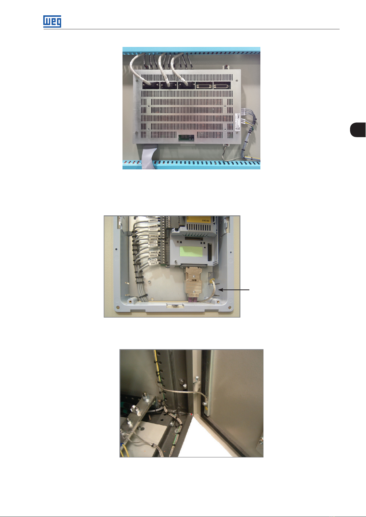
Installation and Connection
Figure 3.53: ICUP shield fastened to the panel
The control rack must be grounded using a flat flexible braid with minimum width of 5 mm and minimum section
of 3 mm² with standard FASTON terminal 6.35 mm (E.g.: TYCO 735075-0 and 180363-2) and lug terminal M4;
see Figure 3.54 on page 3-45.
3
Figure 3.54: Control rack grounding
The panel door must be grounded with a flexible braid.
Figure 3.55: Grounding of the panel door
Flexible braid
CFW-11MW G2 RB | 3-45
Page 65

Installation and Connection
3.4.11.3 Conexões CC11
The control connections (analog inputs/outputs, digital inputs/outputs) must be done to connector XC1 of the
CC11 Control Electronic Board.
The typical connections and functions are shown in Figure 3.56 on page 3-46 and Figure 3.57 on page 3-47.
XC1
Connector
7 AO1 Analog output 1:
volt
3
8 AGND
(24 V )
9 AO2 Analog output 2:
amp
10 AGND
(24 V )
11 DGND* 24 Vdc power supply Connected to the ground (frame) through impedance: 940 Ω resistor
12 COM Digital inputs common
13 24 Vcc 24 Vdc power supply 24 Vdc power supply, ±8 %
14 COM Digital inputs common
15 DI1 Digital input 1:
16 DI2 Digital input 2:
17 DI3 Digital input 3:
18 DI4 Digital input 4:
19 DI5 Digital input 5:
20 DI6 Digital input 6:
21 NF1 Digital output 1 DO1
22 C1
23 N A1
24 NF2 Digital output 2 DO2
25 C2
26 NA2
27 NF3 Digital output 3 DO3
28 C3
29 NA3
Factory Default
Function
DC Link voltage
Reference (0 V) for the
analog outputs
AC current
Reference (0 V) for the
analog outputs
point connection
point connection
General enable
No function
No function
No function
No function
No function
(RL1): Pre-charge OK
(RL2): RUN
(RL3): No fault
Figure 3.56: Signals of connector XC1 - Digital inputs as active high
Galvanic isolation
Resolution: 11 bits
Signal: 0 to 10 V (RL ≥ 10 kΩ) / 0 to 20 mA / 4 to 20 mA (RL ≤ 500 Ω)
Protected against short-circuit
Connected to the ground (frame) through impedance: 940 Ω resistor
in parallel with a 22 nF capacitor
Galvanic isolation
Resolution: 11 bits
Signal: 0 to 10 V (RL ≥ 10 kΩ) / 0 to 20 mA / 4 to 20 mA (RL ≤ 500 Ω)
Protected against short-circuit
Connected to the ground (frame) through impedance: 940 Ω resistor
in parallel with a 22 nF capacitor
in parallel with a 22 nF capacitor
Capacity: 500 mA
6 isolated digital inputs
High level ≥ 18 V
Low level ≤ 3 V
Maximim input voltage ≤ 30 V
Input current: 11 mA @ 24 Vdc
Contact rating:
Maximum voltage: 240 Vac
Maximum current: 1 A
NC - Normally closed contact
C - Common
NO - Normally open contact
Specifications
3-46 | CFW-11MW G2 RB
Page 66
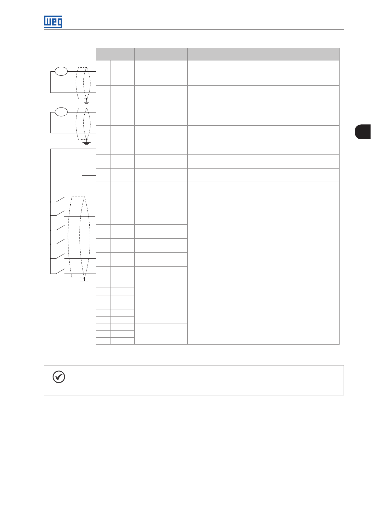
Installation and Connection
rpm
amp
XC1
Connector
7 AO1 Analog output 1:
8 AGND
(24 V )
9 AO2 Analog output 2:
10 AGND
(24 V )
11 DGND* 24 Vdc power supply Connected to the ground (frame) through impedance: 940 Ω resistor
12 COM Digital inputs common
13 24 Vcc 24 Vdc power supply 24 Vdc power supply, ±8 %
14 COM Digital inputs common
15 DI1 Digital input 1:
16 DI2 Digital input 2:
17 DI3 Digital input 3:
18 DI4 Digital input 4:
19 DI5 Digital input 5:
20 DI6 Digital input 6:
21 NF1 Digital output 1 DO1
22 C1
23 NA1
24 NF2 Digital output 2 DO2
25 C2
26 NA2
27 NF3 Digital output 3 DO3
28 C3
29 NA3
Factory Default
Function
DC Link voltage
Reference (0 V) for the
analog outputs
AC current
Reference (0 V) for the
analog outputs
point connection
point connection
General enable
No function
No function
No function
No function
No function
(RL1): Pre-charge OK
(RL2): RUN
(RL3): No fault
Specifications
Galvanic isolation
Resolution: 11 bits
Signal: 0 to 10 V (RL ≥ 10 kΩ) / 0 to 20 mA / 4 to 20 mA (RL ≤ 500 Ω)
Protected against short-circuit
Connected to the ground (frame) through impedance: 940 Ω resistor
in parallel with a 22 nF capacitor
Galvanic isolation
Resolution: 11 bits
Signal: 0 to 10 V (RL ≥ 10 kΩ) / 0 to 20 mA / 4 to 20 mA (RL ≤ 500 Ω)
Protected against short-circuit
Connected to the ground (frame) through impedance: 940 Ω resistor
in parallel with a 22 nF capacitor
in parallel with a 22 nF capacitor
Capacity: 500 mA
6 isolated digital inputs
High level ≥ 18 V
Low level ≤ 3 V
Maximim input voltage ≤ 30 V
Input current: 11 mA @ 24 Vdc
Contact rating:
Maximum voltage: 240 Vac
Maximum current: 1 A
NC - Normally closed contact
C - Common
NO - Normally open contact
3
Figure 3.57: Signals of connector XC1 - Digital inputs as active low
NOTE!
To use the digital inputs as active low, it is necessary to remove the jumper between XC1: 11 and 12
and change it to XC1: 12 and 13.
CFW-11MW G2 RB | 3-47
Page 67

Installation and Connection
ON
S1
1 2 3 4
1
Slot 5
Slot 1 (white)
3
XC1
29
Figure 3.58: Connector XC1 and switches to select the signal type of the analog inputs and outputs
As factory default, the analog inputs and outputs are selected within the range from 0 to 10 V; they can be changed
using switch S1.
Table 3.32: Configurations of the switches to select the signal type of the analog inputs and outputs
Signal Factory Default Function
AO1 DC Link voltage S1.1
AO2 Input current S1.2
Setting
Element
Selection
OFF: 4 to 20 mA / 0 to 20 mA
ON: 0 to 10 V (factory default)
OFF: 4 to 20 mA / 0 to 20 mA
ON: 0 to 10 V (factory default)
Factory
Setting
ON
ON
The parameters related to AO1 and AO2 must also be set according to the selection of the switches and desired
values.
For the correct connection of the control, use:
1. Gauge of the cables: 0.5 mm² (20 AWG) to 1.5 mm² (14 AWG).
2. Maximum torque: 0.5 N.m (4.50 lbf.in).
3. Wiring on XC1 must be done with shielded cables separated from the other wiring (power, control in 110/220V,
etc.), according to Table 3.33 on page 3-48. If those cables must cross other cables, it must be done
perpendicularly, keeping the minimum separation distance of 5 cm at the crossing point.
Table 3.33: Wiring separation distance
Wiring Length Minimum Separation Distance
≤ 30 m ≥ 10 cm
> 30 m ≥ 25 cm
3-48 | CFW-11MW G2 RB
Page 68

Installation and Connection
4. The correct connection of the cable shield is shown in Figure 3.59 on page 3-49. Check connection example
of the shield to the ground in Figure 3.60 on page 3-49.
Insulate with tape
Inverter
side
Do not ground
Figure 3.59: Connection of the shield
3
Figure 3.60: Example of connection of the control cable shield
5. Relays, contactors, solenoids or electromechanical braking coils installed close to the converters may generate
interference in the control circuit. To eliminate this effect, RC suppressors must be connected in parallel to the
coils of those devices in case of AC power supply, and freewheel diodes in case of DC power supply.
CFW-11MW G2 RB | 3-49
Page 69

Installation and Connection
3.4.11.4 Typical Drives
Drive 1 - Command via HMI (Local Mode) with General Enable function.
With the factory default setting, it is possible to operate the converter in the local mode. This operating mode is
recommended for users that are using the converter for the first time, as a form of learning.
To start in this operating mode, follow the directions available in Chapter 5 ENERGIZATION AND START-UP on
page 5-1
The DI1 is already programmed to General Enable as a factory default setting (P0263 = 2).
3
Conector XC1
7 AO1
8 AGND (24 V)
9 AO2
10 AGND (24 V)
11 DGND*
12 COM
General
Enable
13 24 Vcc
14 COM
15 DI1
16 DI2
17 DI3
18 DI4
19 DI5
20 DI6
21 NF1
22 C1
23 NA1
24 NF2
25 C2
26 NA2
27 NF3
28 C3
29 NA3
DO1
(RL1)
DO2
(RL2)
DO3
(RL3)
Figure 3.61: Connections in XC1 for drive 1
3.5 INSTALLATIONS ACCORDING TO THE EUROPEAN ELECTROMAGNETIC COMPATIBILITY DIRECTIVE
The CFW-11M G2 RB and CFW-11W G2 RB converters, when correctly installed, meet the requirements of the
EMC Directive 2004/108/EC.
The CFW-11M G2 RB and CFW-11W G2 RB converters were developed for professional applications only. Therefore,
the limits for emission of harmonic currents established by the EN 61000-3-2 and EN 61000-3-2/A14 standards
are not applicable.
3.5.1 Conformal Installation
For conformal installation, use:
Standard CFW-11M G2 RB and CFW-11W G2 RB converter for emission levels according to IEC/EN61800-3
"Adjustable Speed Electrical Power Drive Systems", category C4.
3-50 | CFW-11MW G2 RB
Page 70

Installation and Connection
Input and RFI filter to meet the levels of conducted emission category C3.
Shielded control cables, keeping the separation distance from other cables according to Item 3.4.11.3 Conexões
CC11 on page 3-46.
Grounding of the inverter according to instructions of Item 3.4.6 Input and Grounding Connections on page
3-31 and Item 3.4.11.2 UC11RB G2 Connections on page 3-41.
Instructions for conformal installations applicable to inverters that drive the motor.
3.5.2 Definition of the Standards
IEC/EN 61800-3: "Adjustable Speed Electrical Power Drives Systems".
Environments:
First Environment: environments that include domestic premises, as well as establishments directly connected
without intermediate transformers to the low voltage power line which supplies installations used for domestic
purposes.
Example: houses, apartments, commercial installations or offices located in residential buildings.
Second Environment: environments that include all the buildings other than those directly connected to the low
voltage power line which supplies buildings used for domestic purposes.
Example: industrial areas, technical areas of any building supplied by a dedicated transformer.
Categories:
Category C1: converters with voltage rating below 1000 V and intended for use in the First Environment.
Category C2: converters with a voltage rating below 1000 V intended for use in the First Environment, not provided
with a plug connector or movable installations, must be installed and commissioned by a professional.
Note: a professional is a person or organization familiar with the installation and/or start-up of converters, including
their EMC aspects.
3
Category C3: converters with voltage ratings below 1000 V developed for application in the "Second Environment"
and not designed for application in the "First Environment".
Category C4: converters with voltage rating equal to or higher than 1000 V, or with a current rating equal to or
higher than 400 A or intended for use in complex systems in the Second Environment.
EN 55011: "Threshold values and measuring methods for radio interference from industrial, scientific and medical
(ISM) high-frequency equipment".
Class B: equipment intended for use in the low voltage power supply network (residential, commercial and light
industrial environments).
Class A1: equipment intended for use in the low voltage power supply network. Restricted distribution.
Note: it must be installed and commissioned by a professional when applied in the low voltage power supply
network.
Class A2: equipment intended for use in industrial environments.
CFW-11MW G2 RB | 3-51
Page 71

Installation and Connection
3.5.3 Emission and Immunity Levels Met
Table 3.34: Emission and immunity levels met
EMC Phenomenon Basic Standard Level
Emission:
Mains terminal disturbance voltage
Frequency range: 150 kHz to 30 MHz)
Electromagnetic radiation disturbance
Frequency range: 30 kHz to 1 GHz
Immunity:
3
Electrostatic discharge (ESD) IEC/EN61000-4-2
Fast transient-burst IEC/EN61000-4-4
Conducted radio-frequency common mode IEC/EN61000-4-6
Surges IEC/EN61000-4-5
Radio-frequency electromagnetic field IEC/EN61000-4-3
IEC/EN61800-3
Category C3
Category C4
4 kV discharge per contact and 8 kV discharge
through the air
2 kV/5 kHz (coupling capacitor) input cables
1 kV/5 kHz control cables
2 kV/5 kHz (coupling capacitor) motor cables
0.15 to 80 Mhz; 10 V; 80 % AM (1 kHz)
Motor and control cables
1.2/50 µs, 8/20 µs
1 kV line-to-line coupling
2 kV line-to-ground coupling
80 to 1000 MHz
10 V/m
80 % AM (1 kHz)
3-52 | CFW-11MW G2 RB
Page 72

HMI
4 HMI
This chapter contains the following information:
HMI keys and functions.
Indications on the display.
Parameter structure.
4.1 HMI-CFW11M G2 HUMAN MACHINE INTERFACE
Through the HMI, it is possible to control the converter, view and adjust all the parameters. The navigation has
the option of sequential access to the parameters or by groups (Menu).
4
Left soft key: function defined by the next
directly above on the display
1. Increases the parameter content
2. Previous group of the parameter group
list
Battery:
NOTE!
The battery is only necessary to maintain the operation of the internal clock when the inverter is
deenergized. In case the battery is low, or not installed on the HMI, the clock time becomes incorrect
and alarm A181 – "Clock with invalid value" will be indicated every time the inverter is turned on.
Right soft key: function defined by the next
directly above on the display
1. Decreases the parameter content
2. Selects the next group of the parameter
group list
Not useNot use
Not useNot use
Not use
Figure 4.1: HMI Keys
CFW-11MW G2 RB | 4-1
Page 73

HMI
The life expectation of the battery is approximately 10 years. Replace the battery, when necessary, by a CR2032
battery.
1 2 3
Cover
4
Cover for battery access
4 5 6
Remove the battery with the
help of a screwdriver positioned
in the right side
7 8
Press the cover and rotate it
counterclockwise
HMI without the battery
Remove the cover
Install the new battery positioning it
first at the left side
Press the battery for its insertion
NOTE!
At the end of the battery useful life, do not dispose it in common garbage, but in a proper place for
batteries.
4-2 | CFW-11MW G2 RB
Put the cover back and rotate it clockwise
Figure 4.2: HMI battery replacement
Page 74

HMI
Installation:
The HMI can be installed or removed from the converter with the converter turned on or off.
Whenever the converter is turned on, the display goes to the Monitoring Mode. For the factory setting, a screen
similar to Figure 4.3 on page 4-3 (a) will be shown. By setting proper parameters, other variables can be shown
in the monitoring mode or the content of the parameters can be presented as bar graphs or larger characters as
shown inFigure 4.3 on page 4-3 (b) and (c).
Mode indication:
LOC: local mode
Real power
REM: remote mode
RB Control
Converter status:
- Run
- Ready
- Config
- Last fault: FXXX
- Last alarm: AXXX
- etc
Function of the left soft key
Run RB + LOC 618 V
A
V
V
DC link voltage in Volts
Run RB + LOC 618V
400 A
618 V
380 V
12:35 Men u
Function of the right soft key
Indication of the time
Adjusted in:
P0197, P0198, an d P0199
(a) Monitoring mode screen at the factory setting
Monitoring parameters:
- Input current
100%
77%
100%
12:35 Men u
(b) Example of a screen in monitoring mode by bar graph
- DC Link Voltage
- Line Voltage in V (P0002)
P0205, P0206 and P0207: selection of the parameters
that will be shown in the monitoring mode
Monitoring parameters:
- Input current in Amps
- DC link voltage in V
- Line voltage in V (P0002)
P0205, P0206 and P0207: selection of parameters
that will be displayed in the monitoring mode
4
Run RB + LOC 618V
Content of the parameter defined in P0205, P0206
400
A
12:35 Men u
(c) Example of a screen in monitoring mode with a variable in bigger letters
Figure 4.3: (a) to (c) Monitoring modes of the HMI display
or P0207 with bigger characters
Parameters not shown must be programmed to
zero in P0205, P0206 or P0207
CFW-11MW G2 RB | 4-3
Page 75

HMI
4.2 PARAMETER STRUCTURE
When the right soft key is pressed in the monitoring mode ("Menu"), the first four parameter groups are shown on
the display. An example of parameter group structure is shown in Table 4.1 on page 4-4. The number and name
of the groups may change depending on the software version used. For further details on the existing groups in
the software version in use, refer to the programming manual.
Table 4.1: Parameter groups
Level 0 Level 1 Level 2 Level 3
00 ALL PARAMETERS
20 Link Voltage
90 Current Regulator
21 Control
4
Monitoring
01 PARAMETER GROUPS
02 ORIENTED START-UP
03 CHANGED PARAMETERS
04 BACKUP PARAMETERS
05 I/O CONFIGURATION
06 FAULT HISTORY
07 READ ONLY PARAMETERS
22 HMI
24 Analog Outputs
25 Digital Inputs
26 Digital Outputs
27 Converter Data
28 Protections
24 Analog Outputs
25 Digital Inputs
26 Digital Outputs
91 Reactive Regulator
92 Current Limits
93 DC Link Regulator
4-4 | CFW-11MW G2 RB
Page 76

Energization and Start-Up
5 ENERGIZATION AND START-UP
This chapter explains:
How to check and prepare the converter before energizing it.
How to energize and check the success of the energization.
5.1 PREPARATION AND ENERGIZATION
The converter must have already been installed according to Chapter 3 INSTALLATION AND CONNECTION on
page 3-1. If the drive design is different from the typical drives suggested, the steps below may also be followed.
DANGER!
Always disconnect the general power supply before making any connections.
1. Configure DIP switch S1 located on the ICUP board, according to the rated voltage of the UP11 G2 or UP11W
G2 used on the drive, Table 3.29 on page 3-43.
2. Configure the number of UP11 G2 or UP11W G2 connected in parallel through DIP switch S2 located on the
ICUP board, according to Table 3.31 on page 3-43.
3. Check if the power, grounding and control connections are correct and firm.
4. Remove all the materials left inside the drive.
5. Check all grounding connections (panel, door where the control is installed, etc.).
6. In the case of UP11W G2 (water-cooled):
a. Make a pressure test on the Cooling System to check for leaks.
b. Turn on the Cooling System and set the flow and the incoming water temperature according to the values
of Table 3.19 on page 3-33.
c. Keep the water flowing for five minutes and check for leaks on the hydraulic connections.
7. Energize the control (supply +24 Vdc).
8. Close the panel doors.
9. The HMI must indicate undervoltage with the electronics energized and the power units de-energized. Parameter
P0004 (Voltage on the DC Link) will indicate approximately 15 Vdc.
5
10. Measure the voltage of the line and check if it is within the allowed range, according to Chapter 8 TECHNICAL
DATA on page 8-1.
11. Check that the automatic hardware identification has recognized the converter current properly, parameter
P0295. The converter current must be compatible with the number of power units installed.
12. Set parameter P0296 according to the rated voltage of the input line.
13. Command the drive, pre-charge the link, and close the main circuit breaker/contactor.
14. Enable the PWM pulses via DI.
15. Check that the DC link voltage indicated in P0004 is close to the P0151 value.
16. Check the success of the energization.
CFW-11MW G2 RB | 5-1
Page 77

Energization and Start-Up
17. The display must show the standard monitoring screen (Figure 4.3 on page 4-3 (a)), the status LED must
turn on and remain on in green.
18. Follow the start-up routine of the output inverters according to the directions contained in the specific manual.
5.2 START-UP
The start-up can be simply explained in three steps, using the programming resources with the existing parameter
groups Oriented Start-Up and Basic Application.
Sequence:
1. Set the password to change parameters.
2. Execution of the Oriented Start-Up routine.
3. Setting the parameters of the Basic Application group.
5
5.2.1 Password Setting in P0000
Step Action/Result Display Indication Step Action/Result Display Indication
Monitoring Mode
Press "Menu" (right
1
soft key)
Group "00 ALL
PARAMETERS" is
2
already selected
Press "Select"
Run RB + LOC 618 V
400 A
618 V
380 V
15:45 Menu
Run RB + LOC 618V
00 ALL PARAMETERS
01 PARAMETER GROUPS
02 ORIENTED START-UP
03 CHANGED PARAMETERS
Return 15:45 Select
When number 5 is
displayed in the keypad,
5
press "Save"
If the setting has been
properly performed,
the keypad should
6
display "Access to
Parameters P0000: 5"
Press "Return" (left
Run RB + LOC 618V
P0000
Access to Parameters
5
Return 15:45 Salvar
Run RB + LOC 618V
Access to Parameters
P0000: 5
Line Voltage
P0002: 380V
Return 15:45 Select
soft key)
Parameter "Access to
Parameters P0000: 0"
3
is already selected
Pressione "Select"
To set the password,
press the Up Arrow
4
5 is displayed in the
keypad
until number
Run RB + LOC 618V
Access to Parameters
P0000: 0
Line Voltage
P0002: 380 V
Return 15:45 Select
Run RB + LOC 618V
P0000
Access to Parameters
0
Return 15:45 Save
7 Press "Return"
The display returns to
8
the Monitoring Mode
Run RB + LOC 618V
00 ALL PARAMETERS
01 PARAMETER GROUPS
02 ORIENTED START-UP
03 CHANGED PARAMETERS
Return 15:45 Select
Run RB + LOC 618V
400 A
618 V
380 V
15:45 Menu
Figure 5.1: Sequence for allowing parameter change via P0000
5.2.2 Oriented Start-up
To simplify the setting of the converter, there is a parameter group called Oriented Start-Up. Within this group is
parameter P0317, which can be used to access the Oriented Start-Up.
The Oriented Start-up routine shows the main parameters on the HMI in a logical sequence, so that their setting,
according to the operating conditions, prepares the inverter for operation according to the line used.
In order to enter the Oriented Start-Up routine, follow the sequence shown in Figure 5.2 on page 5-3, first
changing P0317 = 1, and then setting the other parameters as they are displayed on the HMI.
The setting of the parameters displayed in this operating mode automatically changes the content of other internal
variables and/or parameters of the converter.
During the Oriented Start-Up routine, the "Config" (Configuration) status will be indicated on the top left part of
the HMI.
5-2 | CFW-11MW G2 RB
Page 78

Energization and Start-Up
Step Action/Result Display Indication Step Action/Result Display Indication
Monitoring Mode
1
Press "Menu" (right
soft key)
Group "00 ALL
PARAMETERS"
2
is already selected
Ready RB + LOC 618V
0 A
618 V
380 V
13:48 Menu
Ready RB + LOC 618V
00 ALL PARAMETERS
01 PARAMETER GROUPS
02 ORIENTED START-UP
03 CHANGED PARAMETERS
Return 13:48 Select
The parameter value is
modified to "P0317 =
7
[0 0 1] Ye s"
Press "Save"
At this point the
Oriented Start-up
routine starts and the
"Config" status is
displayed at the top left
corner of the keypad.
The parameter
"Language P0201:
English" is already
selected
8
If needed, change the
language by pressing
"Select". Then, press
or
to scroll through the
available options and
press "Save" to select
a different language
Ready RB + LOC 618V
P0317
Oriented Start-up
[001] Yes
Return 13:48 Save
Config RB + LOC 618V
Language
P0201: English
DI1 Function
P0263: General Enable
Reset 13:48 Select
5
Group "01
PARAMETER
3
GROUPS" is selected
Group "02 ORIENTED
STA R T- U P " is then
4
selected
Press "Select"
Parameter "Oriented
Start-Up P0317: No" is
5
already selected
Press "Select"
The value of "P0317 =
[000] No" is displayed
6
Ready RB + LOC 618V
00 ALL PARAMETERS
01 PARAMETER GROUPS
02 ORIENTED START-UP
03 CHANGED PARAMETERS
Return 13:48 Select
Ready RB + LOC 618V
00 ALL PARAMETERS
01 PARAMETER GROUPS
02 ORIENTED START-UP
03 CHANGED PARAMETERS
Return 13:48 Select
Ready RB + LOC 618V
Oriented Start-Up
P0317: No
Return 13:48 Select
Ready RB + LOC 618V
P0317
Oriented Start-up
[000] No
Return 13:48 Save
If needed, change
the value of P0263
according to the
application. To do so,
press "Select"
It is necessary to have
9
one DI set to General
Enable in order the
regenerative converter
can be enabled
If needed, change
the value of P0296
according to the line
10
voltage. To do so,
press "Select". This
change will affect P0151
If needed, change
the value of P0298
according to the
application. To do so,
press "Select". The
time and the activation
11
level of the IGBT’s
overload protection will
be affected as well
To complete the
Oriented Start-Up
routine, press "Reset"
(left soft key)
After few seconds, the
12
display returns to the
Monitoring Mode
Config RB + LOC 618V
DI1 Function
P0263: General Enable
Line Rated Voltage
P0296: 440 - 460V
Reset 13:48 Select
Config RB + LOC 618V
DI1 Function
P0263: General Enable
Line Rated Voltage
P0296: 440 - 460 V
Reset 13:48 Select
Config RB + LOC 618V
Switching Frequency
P0297: 2.5 kHz
Application
P0298: Normal Duty (ND)
Reset 13:48 Select
Ready RB + LOC 618V
0 A
618 V
380 V
13:48 Menu
Figure 5.2: Oriented start-up
CFW-11MW G2 RB | 5-3
Page 79

Energization and Start-Up
5.3 DATE AND TIME SETTING
Step Action/Result Display Indication Step Action/Result Display Indication
Parameter "Day P019 4"
is already selected
If needed, set P0194
according to the actual
day. To do so, press
"Select" and then
6
change P0194 value
Follow the same steps
or to
Monitoring Mode
1
Press "Menu" ("right
soft key")
Run RB + LOC 618V
400 A
618 V
380 V
16:10 Menu
to set parameters
"Month P0195" to
"Seconds P0199"
Group "00 ALL
PARAMETERS"
2
is already selected
Run RB + LOC 618V
00 ALL PARAMETERS
01 PARAMETER GROUPS
02 ORIENTED START-UP
03 CHANGED PARAMETERS
Return 16:10 Select
5
Group "01 PARAMETER
GROUPS" is selected
3
Press "Select"
Ready RB + LOC 618V
00 ALL PARAMETERS
01 PARAMETER GROUPS
02 ORIENTED START-UP
03 CHANGED PARAMETERS
Return 13:48 Select
Once the setting of
P0199 is over, the Real
Time Clock is now
7
updated.
Press "Return" (left
soft key)
Press "Return"
8
Run RB + LOC 618V
Day
P0194: 06
Mes
P0195: 10
Return 16:10 Select
Run RB + LOC 618V
Minutes
P0198: 11
Seconds
P0199: 34
Return 18:11 Select
Run RB + LOC 618V
20 DC Link Voltage
21 Control
22 HMI
23Analog Inputs
Return 18:11 Select
A new list of groups is
displayed and group
"20 DC Link Voltage"
4
is selected
Press until you
Run RB + LOC 618V
20 DC Link Voltage
21 Control
22 HMI
23 Analog Inputs
Return 16:10 Select
Press "Return"
9
Run RB + LOC 618V
00 ALL PARAMETERS
01 PARAMETER GROUPS
02 ORIENTED START-UP
03 CHANGED PARAMETERS
Return 18:11 Select
reach group "22 HMI"
Group "22 HMI" is
5
selected
Press "Select"
Run RB + LOC 618V
20 DC Link Voltage
21 Control
22 HMI
23Analog Inputs
Return 16:10 Select
The display returns to
10
the Monitoring Mode
Run RB + LOC 618V
400 A
618 V
380 V
18:11 Menu
Figure 5.3: Date and time setting
5.4 LOCKING OF PARAMETER MODIFICATION
In case you want to prevent unauthorized people from changing parameters, just change the content of P0000 to
a value different from 5. Follow the same procedure presented in Item 5.2.1 Password Setting in P0000 on page
5-2. To change the password, refer to P0200 in the programming manual.
5.5 HOW TO CONNECT A PC
NOTE!
Always use standard host/device shielded USB cable. Cables without shield may cause
communication errors.
Example of cables: Samtec:
- USBC-AM-MB-B-B-S-1 (1 meter).
- USBC-AM-MB-B-B-S-2 (2 meters).
- USBC-AM-MB-B-B-S-3 (3 meters).
The USB connection is galvanically isolated from the electric line and other high voltages inside
the inverter. However, it is not isolated from the protective earth (PE). Use an isolated laptop to
hook the USB connector or desktop with connection to the same protective earth of the inverter.
5-4 | CFW-11MW G2 RB
Page 80

5.6 FLASH MEMORY MODULE
Location according to Figure 5.4 on page 5-5.
Flash Memory Module
Energization and Start-Up
5
Figure 5.4: Detail of location of the flash memory module
Functions:
It stores an image of the converter parameters.
It allows transferring parameters stored in the flash memory module to the converter.
It allows transferring firmware stored in the flash memory module to the converter.
For further details, refer to the Programming Manual of the CFW-11 RB.
ATTENTION!
To connect or disconnect the flash memory module, first turn off the converter, wait for the discharge
of the capacitors and then turn off the electronics power supply (+24 V).
CFW-11MW G2 RB | 5-5
Page 81
Energization and Start-Up
5.7 OPERATION WITH A REDUCED NUMBER OF POWER UNITS
The CFW-11M G2 RB and the CFW-11W G2 RB can operate with a reduced number of power units and reduced
power for a short time. That operating mode is called "Reduced Power Mode". It may be used in critical processes
in which you do not want a whole machine to stop when one power unit fails, enabling the operation with reduced
power until you have a power unit for replacement.
The general scheme of a drive with 5 UP11 is shown in Figure 3.31 on page 3-26. The reduced power mode
works as a drive of up to 2 UP11.
Assume that in the drive of Figure 3.31 on page 3-26, composed of 5 UP11, UP11 number4 fails. To reestablish
the drive operation with reduced power (Reduced Power Mode), you must follow the steps below:
1. Disconnect the power supply from the drive.
2. Identify the defective UP11 (in this case, number 4).
5
3. Disconnect the power and control of UP11 number4, according to Figure 5.5 on page 5-7.
4. Move the control connections on the ICUP board, as shown in Figure 5.6 on page 5-8. Connect the control
cables of UP11 number 5 to position 4 of the ICUP board. Thus, UP11 5 becomes UP11 4.
5. Configure the new number of UP11 through DIP switch S2 located on the ICUP board, according to Tabl e
3.31 on page 3-43.
6. Change DIP switch S1:4 to ON; thus, the control will be informed that the CFW-11M G2 RB or CFW-11W G2 RB
drive is operating with a reduced number of UP11.
ATTENTION!
It is recommended that the drive operate short of one UP11 at most.
7. Reconnect only the power supply of the drive control.
8. Alarm A420 will be indicated (Reduced Power Mode), informing that the CFW-11M G2 RB or CFW-11W G2
RB is operating in the reduced power mode.
9. Check if parameters P0295 (Rat. Curr. ND/HD Inv.) and P0296 (Rated Line Voltage) are according to the voltage
and the number of connected UP11.
5-6 | CFW-11MW G2 RB
Page 82
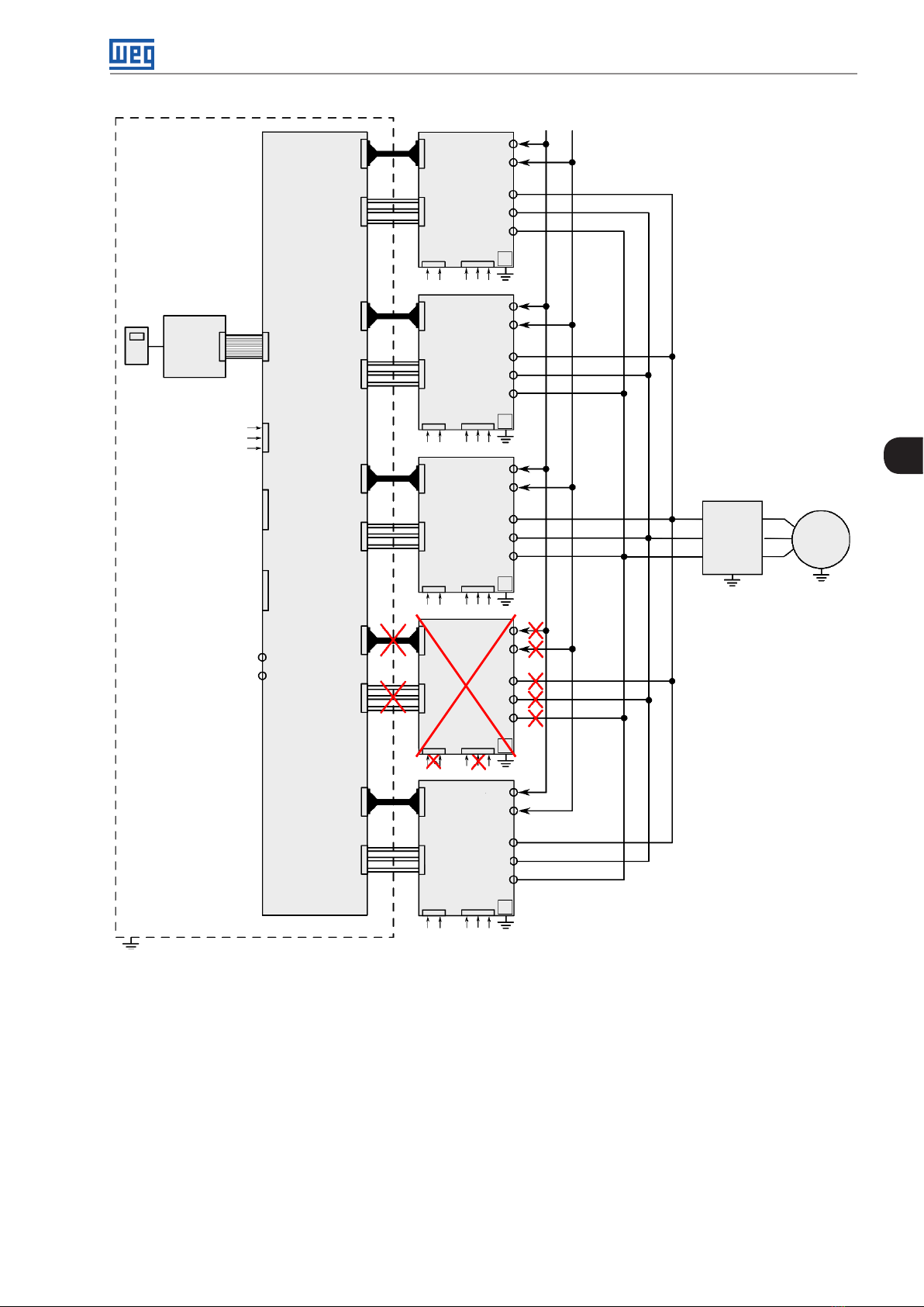
Energization and Start-Up
UC11 R B
HMI
CC11
+UD -UD
ICUP
XC40AUH1...WL1
UP11
+UD
-UD
U
V
W
XC33
220 Vac
XC6
24 Vcc
1
+UD
-UD
XC60
XC60
UP11
U
V
W
24 VCC
Not
Digital
1
2
3
XC33
220 Vac
XC40C XC40B
used
XC33
XC5 XC67 XC9
inputs
220 Vac
24 Vcc
UP11
24 Vcc
XC6
XC6
+UD
-UD
2
5
U
V
W
3
U
V
Filter
W
Mains
+UD
UP11
-UD
U
V
Not
BR
used
Error_BR
XC40D
W
XC6
XC33
4
220 Vac
24 Vcc
+UD
UP11
1 1 1 11
24 Vcc
XC6
2 2 2 22
-UD
U
V
W
5
3 3 3 33
XC40 XC40 XC40 XC40XC40
UH5...WL5 UH4...WL4 UH3...WL3 UH2...WL2XC40E
UH...WL UH...WL UH...WL UH...WLUH...WL
XC33
1 1 1 11
2 2 2 22
220 Vac
Figure 5.5: Disconnection of the power and control cables of UP11 number 4
CFW-11MW G2 RB | 5-7
Page 83

Energization and Start-Up
UC11 R B
ICUP
+UD
XC40AUH1...WL1
-UD
UP11
+UD -UD
U
V
W
XC6
XC33
220 Vac
1
24 Vcc
+UD
-UD
CC11
HMI
XC60
XC60
UP11
U
V
W
XC6
1
2
3
5
24 VCC
XC33
220 Vac
2
24 Vcc
+UD
Not
Digital
XC40C XC40B
used
XC33
XC5 XC67 XC9
inputs
220 Vac
UP11
24 Vcc
XC6
-UD
U
V
W
U
V
Filter
W
Mains
3
+UD
UP11
-UD
U
V
Not
BR
used
Error_BR
XC40D
W
XC6
XC33
220 Vac
4
24 Vcc
+UD
XC40 XC40 XC40 XC40XC40
-UD
5-8 | CFW-11MW G2 RB
U
UP11
UH5...WL5 UH4...WL4 UH3...WL3 UH2...WL2XC40E
UH...WL UH...WL UH...WL UH...WLUH...WL
XC33
1 1 1 1
2 2 2 2
220 Vac
XC6
1 1 1 1
2 2 2 2
24 Vcc
V
W
5
3 3 3 3
Figure 5.6: Moving the control connections on the ICUP board
Page 84

Troubleshooting and Maintenance
6 TROUBLESHOOTING AND MAINTENANCE
This chapter presents:
The list of all faults and alarms.
Most probable causes for each fault and alarm.
The list of the most common problems and corrective actions.
Instructions for periodical inspections of the product and preventive maintenance.
6.1 OPERATION OF THE FAULTS
When a fault (FXXX) is identified, what occurs is:
Locking of the PWM pulses.
Indication on the display of the fault description and code.
The "STATUS" LED flashes red.
The relay programmed for "NO FAULTS" is turned off.
Saving of some data on the EEPROM of the control circuit:
- The fault or alarm code occurred (it moves the nine previous faults).
- The status of the hours enabled (P0043) and energized (P0042) counter.
For the converter to return to normal operation right after the occurrence of a fault, it is necessary to reset it,
which can be done as follows:
- Switching off the power supply and switching it back on (power-on reset).
- Pressing the (manual reset) key.
- Via soft key "Reset".
- Automatically by means of the P0340 setting (auto-reset).
- Via digital input: DIx = 20 (P0263 to P0270).
When an alarm (AXXX) is identified, what occurs is: re:
Indication on the display of the alarm description and code.
The "STATUS" LED becomes yellow.
The PWM pulses are not blocked and the converter remains in operation.
6
CFW-11MW G2 RB | 6-1
Page 85

Troubleshooting and Maintenance
6.2 ALARMS, FAULTS AND POSSIBLE CAUSES
Table 6.1: Alarms, faults and possible causes
Fault/Alarm Description Possible Causes
F006
Grid Phase Fault/Unbal.
F020
24 Vdc Power Supply
Undervoltage
F021
DC Link Undervoltage
6
F022
DC Link Overvoltage
(1)
F030
Arm U Fault
(1)
F034
Arm V Fault
(1)
F038
Arm W Fault
A047
Overload on the IGBTs
F048
Overload on the IGBTs
F070
Overcurr. / Short circ.
F071
Overcurrent at the Input
F0 74
Ground Fault
F080
CPU Fault (Watchdog)
F082
Copy Function Fault
F084
Self-Diagnostics Fault
A088
Communication Lost
A090
External Alarm
Phase loss fault on the grid or wrong phase sequence. Check connections of CSR11 board.
Check connections of the synchronization
transformers.
Check connection with the grid.
Undervoltage on the 24 Vdc power supply that feeds
Voltage on the power supply below 22.8 Vdc.
the control.
Undervoltage on the DC link. Supply voltage too low, producing voltage on the
DC link below the minimum value (read the value
in parameter P0004):
Ud < 385 V - Supply voltage 380 V (P0296 = 1).
Ud < 405 V - Supply voltage 400-415 V (P0296 = 2).
Ud < 446 V - Supply voltage 440-460 V (P0296 = 3).
Ud < 487 V - Supply voltage 480 V (P0296 = 4).
Ud < 530 V – Supply voltage 500-525 V (P0296 = 5).
Ud < 696 V – Supply voltage 550-575 V (P0296 = 6).
Ud < 605 V - Supply voltage 600 V (P0296 = 7).
Ud < 696 V – Supply voltage 660-690 V (P0296 = 8).
Phase loss at the input.
Fault on the pre-charge circuit.
Parameter P0296 selected for use above the rated
line voltage.
Overvoltage on the DC link. Supply voltage too high, producing voltage on the
DC link above the maximum value:
Ud > 800 V - Models 380 - 480 V (P0296 = 1, 2,
3 and 4).
Ud > 1000 V - Models 500-600 V (P0296 = 5,
6 and 7).
Ud > 1200 V - Models 660-690 V (P0296 = 8).
Driven load inertia too high or deceleration ramp
too fast.
Setting of P0151 too high.
Desaturation on the IGBTs of arm U. Short-circuit between phases U and V or U and
W of the input.
Desaturation on the IGBTs of arm V. Short-circuit between phases V and U or V and
W of the input.
Desaturation on the IGBTs of arm W. Short-circuit between phases W and U or W and
V of the input.
IGBT overload alarm. High current at the converter input.
IGBT overload fault. High current at the converter input.
Overcurrent or short circuit at the input, DC link. IGBT modules short circuited.
Input overcurrent fault. Input reactance too low.
Setting of P0169 or P0170 too high.
Synchronization circuit connection with one or
more inverted phases.
Overcurrent to ground fault.
Short-circuit to ground in + UD or -UD.
Note:
- It may be disabled by setting P0343 = 0.
Watchdog fault on the microcontroller. Electric noise.
Fault in the copy of parameters. Attempt to copy parameters from the HMI to the
inverter with incompatible software versions.
Self-Diagnostics Fault. Defect on the inverter internal circuits.
Fault in the communication of the HMI with the
control board.
External alarm via DI.
Note:
Poor contact on the HMI cable.
Electric noise on the installation.
Wiring at the DI1 to DI8 inputs open (programmed
for "without external alarm").
- It is necessary to program DI for "without external
fault".
6-2 | CFW-11MW G2 RB
Page 86

Fault/Alarm Description Possible Causes
F091
External Fault
F099
Invalid Current Offset
F101
Invalid Voltage Offset
A105
Injection of Reactive Power in
the Line
F151
Flash Memory Module Fault
Troubleshooting and Maintenance
External alarm via DI.
Note:
- It is necessary to program DI for "without external
fault".
Current measurement circuit has a value out of the
standards for zero current.
Offset calculation error in the reading of the input
voltage (synchronism).
Alarm of injection of reactive current in the line. Line voltage too above the rated value.
Fault on the Flash Memory Module (MMF-01). Flash memory module defective.
Wiring at the DI1 to DI8 inputs open (programmed
for "without external fault").
Defect on internal circuits of the converter.
Main contactor closed before the pre-charge is
completed.
CPU was reset and the main contactor did not
open.
P0180 too low.
Flash memory module not well fitted.
A152
High Internal Air Temperature
F15 3
Internal Air Overtemp.
A156
Undertemperature
F156
Undertemperature
A177
Fan Replacement
A181
Clock with Invalid Value
F182
Pulse Feedback Fault
F183
Overload
IGBTs+Temperature
A300
High Temperature
IGBT U B1
F301
Overtemperature
IGBT U B1
A303
High Temperature
IGBT V B1
F304
Overtemperature
IGBT V B1
A306
High Temperature
IGBT W B1
F307
Overtemperature
IGBT W B1
A309
High Temperature
IGBT U B2
High internal air temperature alarm.
Measured temperature above 75 ºC (167 °F).
Note:
High ambient temperature around the converter
(> 30 °C (86 °F)).
High temperature inside the panel (> 45 °C (113 °F)).
- It can be disabled by setting P0353 = 1 or 3.
Internal air overtemperature fault.
Measured temperature above 80 ºC.
Only one sensor indicates temperature below
-30° C (-22 °F).
Undertemperature fault measured on the IGBT
temperature sensors.
Alarm to replace the fan (P0045 > 50000 hours).
Note:
Ambient temperature around the converter ≤
-30 °C (-22 °F).
Ambient temperature around the converter ≤
-30 °C (-22 °F).
Maximum number of the heatsink fan operating
hours exceeded.
- It may be disabled by setting P0354 = 0.
Alarm of clock with wrong time. Necessary to set the date and time in P0194 to
P0199
HMI battery low, defective or not installed.
Pulse feedback fault. Defect on the internal circuits of the converter.
Defect on the fiber optic.
Defect on cables XC10A, B, C, D or E.
Overtemperature related to IGBT overload
protection.
Alarm of high temperature measured on the
temperature sensor (NTC) of the IGBT of phase U of
book 1. Measured temperature above 110 ºC (230 ºF).
Fault of overtemperature measured on the
temperature sensor (NTC) of the IGBT of phase U of
book 1. Measured temperature above 115 ºC (239 ºF).
Alarm of high temperature measured on the
temperature sensor (NTC) of IGBT of phase V of
book 1. Measured temperature above 110 ºC (230 ºF).
Fault of overtemperature measured on the
temperature sensor (NTC) of IGBT of phase V of
book 1. Measured temperature above 115 ºC (239 ºF).
High ambient temperature around the converter.
Operation with overload.
High ambient temperature (> 45 °C (113 °F)) and
high output current.
Locked or defective fan.
Book heatsink fins too dirty, hindering the air flow.
High coolant temperature (> 45 °C (113 °F) see
Item 3.2.6 Cooling System on page 3-17) and
high output current.
Coolant flow < 20 l/min or clogged tubing.
UP11W heatsink or system heat exchanger rust
inside due to coolant out of the specifications (see
Item 3.2.6 Cooling System on page 3-17).
Fault in the pumps.
Alarm of high temperature measured on the
temperature sensor (NTC) of IGBT of phase W of
book 1. Measured temperature above 110 ºC (230 ºF).
Fault of overtemperature measured on the
temperature sensor (NTC) of IGBT of phase W of
book 1. Measured temperature above 115 ºC (239 ºF).
Alarm of high temperature measured on the
temperature sensor (NTC) of IGBT of phase U of
book 2. Measured temperature above 110 ºC (230 ºF).
6
CFW-11MW G2 RB | 6-3
Page 87

Troubleshooting and Maintenance
Fault/Alarm Description Possible Causes
F310
Overtemperature
IGBT U B2
A312
High Temperature
IGBT V B2
F313
Overtemperature
IGBT V B2
A315
High Temperature
IGBT W B2
F316
Overtemperature
IGBT W B2
A318
High Temperature
IGBT U B3
F319
Overtemperature
IGBT U B3
A321
High Temperature
6
IGBT V B3
F322
Overtemperature
IGBT V B3
A324
High Temperature
IGBT W B3
F325
Overtemperature
IGBT W B3
A327
High Temperature IGBT U B4
F328
Overtemperature
IGBT U B4
A330
High Temperature
IGBT V B4
F331
Overtemperature
IGBT V B4
A333
High Temperature
IGBT W B4
F334
Overtemperature
IGBT W B4
A336
High Temperature
IGBT U B5
F337
Overtemperature
IGBT U B5
A339
High Temperature
IGBT V B5
F340
Overtemperature
IGBT V B5
A342
High Temperature
IGBT W B5
F343
Overtemperature IGBT
W B5
Fault of overtemperature measured on the
temperature sensor (NTC) of the IGBT of phase U of
book 2. Measured temperature above 115 ºC (239 ºF).
Alarm of high temperature measured on the
temperature sensor (NTC) of IGBT of phase V of
book 2. Measured temperature above 110 ºC (230 ºF).
Fault of overtemperature measured on the
temperature sensor (NTC) of IGBT of phase V of
book 2. Measured temperature above 115 ºC (239 ºF).
Alarm of high temperature measured on the
temperature sensor (NTC) of IGBT of phase W of
book 2. Measured temperature above 110 ºC (230 ºF).
Fault of overtemperature measured on the
temperature sensor (NTC) of IGBT of phase W of
book 2. Measured temperature above 115 ºC (239 ºF).
Alarm of high temperature measured on the
temperature sensor (NTC) of IGBT of phase U of
book 3. Measured temperature above 110 ºC (230 ºF).
Fault of overtemperature measured on the
temperature sensor (NTC) of the IGBT of phase U of
book 3. Measured temperature above 115 ºC (239 ºF).
Alarm of high temperature measured on the
temperature sensor (NTC) of IGBT of phase V of
book 3. Measured temperature above 110 ºC (230 ºF).
Fault of overtemperature measured on the
temperature sensor (NTC) of IGBT of phase V of
book 3. Measured temperature above 115 ºC (239 ºF).
Alarm of high temperature measured on the
temperature sensor (NTC) of IGBT of phase W of
book 3. Measured temperature above 110 ºC (230 ºF).
Fault of overtemperature measured on the
temperature sensor (NTC) of IGBT of phase W of
book 3. Measured temperature above 115 ºC (239 ºF).
Alarm of high temperature measured on the
temperature sensor (NTC) of IGBT of phase U of
book 4. Measured temperature above 110 ºC (230 ºF).
Fault of overtemperature measured on the
temperature sensor (NTC) of the IGBT of phase U of
book 4. Measured temperature above 115 ºC (239 ºF).
Alarm of high temperature measured on the
temperature sensor (NTC) of IGBT of phase V of
book 4. Measured temperature above 110 ºC (230 ºF).
Fault of overtemperature measured on the
temperature sensor (NTC) of IGBT of phase V of
book 4. Measured temperature above 115 ºC (239 ºF).
Alarm of high temperature measured on the
temperature sensor (NTC) of IGBT of phase W of
book 4. Measured temperature above 110 ºC (230 ºF).
Fault of overtemperature measured on the
temperature sensor (NTC) of IGBT of phase W of
book 4. Measured temperature above 115 ºC (239 ºF).
Alarm of high temperature measured on the
temperature sensor (NTC) of IGBT of phase U of
book 5. Measured temperature above 110 ºC (230 ºF).
Fault of overtemperature measured on the
temperature sensor (NTC) of the IGBT of phase U of
book 5. Measured temperature above 115 ºC.
Alarm of high temperature measured on the
temperature sensor (NTC) of IGBT of phase V of
book 5. Measured temperature above 110 ºC (230 ºF).
Fault of overtemperature measured on the
temperature sensor (NTC) of IGBT of phase V of
book 5. Measured temperature above 115 ºC (239 ºF).
Alarm of high temperature measured on the
temperature sensor (NTC) of IGBT of phase W of
book 5. Measured temperature above 110 ºC (230 ºF).
Fault of overtemperature measured on the
temperature sensor (NTC) of IGBT of phase W of
book 5. Measured temperature above 115 ºC (239 ºF).
High ambient temperature (> 45 °C (113 °F)) and
high output current.
Locked or defective fan.
Book heatsink fins too dirty, hindering the air flow.
High coolant temperature (> 45 °C (113 °F) see
Item 3.2.6 Cooling System on page 3-17) and
high output current.
Coolant flow < 20 l/min or clogged tubing.
UP11W heatsink or system heat exchanger rust
inside due to coolant out of the specifications (see
Item 3.2.6 Cooling System on page 3-17).
Fault in the pumps.
6-4 | CFW-11MW G2 RB
Page 88
Fault/Alarm Description Possible Causes
A345
High Load IGBT U B1
F346
Overload on IGBT U B1
A348
High Load IGBT V B1
F349
Overload on IGBT V B1
A351
High Load IGBT W B1
F352
Overload on IGBT W B1
A354
High Load IGBT U B2
F355
Overload on IGBT U B2
A357
High Load IGBT V B2
F358
Overload on IGBT V B2
A360
High Load IGBT W B2
F361
Overload on IGBT W B2
A363
High Load IGBT U B3
F364
Overload on IGBT U B3
A366
High Load IGBT V B3
F367
Overload on IGBT V B3
A369
High Load IGBT W B3
F370
Overload on IGBT W B3
A372
High Load IGBT U B4
F373
Overload on IGBT U B4
A375
High Load IGBT V B4
F376
Overload on IGBT V B4
A378
High Load IGBT W B4
F379
Overload on IGBT W B4
A381
High Load IGBT U B5
F382
Overload on IGBT U B5
A384
High Load IGBT V B5
F385
Overload on IGBT V B5
A387
High Load IGBT W B5
F388
Overload on IGBT W B5
Troubleshooting and Maintenance
Alarm of overload on the IGBT of phase U of book 1. High current at the converter input (see Figure 8.1
on page 8-4).
Fault of overload on the IGBT of phase U of book 1.
Alarm of overload on the IGBT of phase V of book 1.
Fault of overload on the IGBT of phase V of book 1.
Alarm of overload on the IGBT of phase W of book 1.
Alarm of overload on the IGBT of phase W of book 1.
Alarm of overload on the IGBT of phase U of book 2.
Fault of overload on the IGBT of phase U of book 2.
Alarm of overload on the IGBT of phase V of book 2.
Fault of overload on the IGBT of phase V of book 2.
Alarm of overload on the IGBT of phase W of book 2.
Fault of overload on the IGBT of phase W of book 2.
6
Alarm of overload on the IGBT of phase U of book 3.
Fault of overload on the IGBT of phase U of book 3.
Alarm of overload on the IGBT of phase V of book 3.
Fault of overload on the IGBT of phase V of book 3.
Alarm of overload on the IGBT of phase W of book 3.
Fault of overload on the IGBT of phase W of book 3.
Alarm of overload on the IGBT of phase U of book 4.
Fault of overload on the IGBT of phase U of book 4.
Alarm of overload on the IGBT of phase V of book 4.
Fault of overload on the IGBT of phase V of book 4.
Alarm of overload on the IGBT of phase W of book 4.
Fault of overload on the IGBT of phase W of book 4.
Alarm of overload on the IGBT of phase U of book 5.
Fault of overload on the IGBT of phase U of book 5.
Alarm of overload on the IGBT of phase V of book 5.
Fault of overload on the IGBT of phase V of book 5.
Alarm of overload on the IGBT of phase W of book 5.
Fault of overload on the IGBT of phase W of book 5.
CFW-11MW G2 RB | 6-5
Page 89

Troubleshooting and Maintenance
Fault/Alarm Description Possible Causes
A390
Current Unbalance
Phase U B1
A391
Current Unbalance
Phase V B1
A392
Current Unbalance
Phase W B1
A393
Current Unbalance
Phase U B2
6
A394
Current Unbalance
Phase V B2
A395
Current Unbalance
Phase W B2
A396
Current Unbalance
Phase U B3
A397
Current Unbalance
Phase V B3
A398
Current Unbalance
Phase W B3
A399
Current Unbalance
Phase U B4
A400
Current Unbalance
Phase V B4
Alarm of current unbalance of phase U book 1.
It indicates an unbalance of 20 % in the current
distribution between this phase and the smallest
current of the same phase in another book, only
when the current in this phase is higher than 75 %
of its rated value.
Alarm of current unbalance of phase V book 1. It
indicates an unbalance of 20 % in the current
distribution between this phase and the smallest
current of the same phase in another book, only
when the current in this phase is higher than 75 %
of its rated value.
Alarm of current unbalance of phase W book 1.
It indicates an unbalance of 20 % in the current
distribution between this phase and the smallest
current of the same phase in another book, only
when the current in this phase is higher than 75 %
of its rated value.
Alarm of current unbalance of phase U book 2.
It indicates an unbalance of 20 % in the current
distribution between this phase and the smallest
current of the same phase in another book, only
when the current in this phase is higher than 75 %
of its rated value.
Alarm of current unbalance of phase V book 2. It
indicates an unbalance of 20 % in the current
distribution between this phase and the smallest
current of the same phase in another book, only
when the current in this phase is higher than 75 %
of its rated value.
Alarm of current unbalance of phase W book 2.
It indicates an unbalance of 20 % in the current
distribution between this phase and the smallest
current of the same phase in another book, only
when the current in this phase is higher than 75 %
of its rated value.
Alarm of current unbalance of phase U book 3.
It indicates an unbalance of 20 % in the current
distribution between this phase and the smallest
current of the same phase in another book, only
when the current in this phase is higher than 75 %
of its rated value.
Alarm of current unbalance of phase V book 3. It
indicates an unbalance of 20 % in the current
distribution between this phase and the smallest
current of the same phase in another book, only
when the current in this phase is higher than 75 %
of its rated value.
Alarm of current unbalance of phase W book 3.
It indicates an unbalance of 20 % in the current
distribution between this phase and the smallest
current of the same phase in another book, only
when the current in this phase is higher than 75 %
of its rated value.
Alarm of current unbalance of phase U book 4.
It indicates an unbalance of 20 % in the current
distribution between this phase and the smallest
current of the same phase in another book, only
when the current in this phase is higher than 75 %
of its rated value.
Alarm of current unbalance of phase V book 4. It
indicates an unbalance of 20 % in the current
distribution between this phase and the smallest
current of the same phase in another book, only
when the current in this phase is higher than 75 %
of its rated value.
Poor electrical connection between the DC link
and the power unit.
Poor electrical connection between input U, V and
W of the power unit and the filter.
Note: In case of quick accelerations and brakes,
this alarm may be momentarily indicated,
disappearing after some seconds. This does not
indicate a malfunction of the inverter. In case this
alarm persists when the motor is operating at
constant speed, it is an indication of abnormal
current distribution between the power units.
6-6 | CFW-11MW G2 RB
Page 90

Troubleshooting and Maintenance
Fault/Alarm Description Possible Causes
A401
Current Unbalance
Phase W B4
A402
Current Unbalance
Phase U B5
A403
Current Unbalance
Phase V B5
A404
Current Unbalance
Phase W B5
F408
Fault on the Cooling System
F410
External Fault
(1) For the CFW11M G2 RB or CFW11W G2 RB, the HMI does not indicate in which UP11 G2 (UP11W G2) the fault occurred. LEDs on the ICUP board indicate
which UP11 (UP11W) caused the fault, Figure 6.1 on page 6-7. When the reset is executed, the LEDs turn off and turn back on if the fault persists.
Alarm of current unbalance of phase W book 4.
It indicates an unbalance of 20 % in the current
distribution between this phase and the smallest
current of the same phase in another book, only
when the current in this phase is higher than 75 %
of its rated value.
Alarm of current unbalance of phase U book 5.
It indicates an unbalance of 20 % in the current
distribution between this phase and the smallest
current of the same phase in another book, only
when the current in this phase is higher than 75 %
of its rated value.
Alarm of current unbalance of phase V book 5. It
indicates an unbalance of 20 % in the current
distribution between this phase and the smallest
current of the same phase in another book, only
when the current in this phase is higher than 75 %
of its rated value.
Alarm of current unbalance of phase W book 5.
It indicates an unbalance of 20 % in the current
distribution between this phase and the smallest
current of the same phase in another book, only
when the current in this phase is higher than 75 %
of its rated value.
This fault/alarm is linked to the configuration of
parameters P0832 and P0833.
Function of input DIM 1.
Function of input DIM 2.
Poor electrical connection between the DC link
and the power unit.
Poor electrical connection between input U, V and
W of the power unit and the filter.
Note: In case of quick accelerations and brakes,
this alarm may be momentarily indicated,
disappearing after some seconds. This does not
indicate a malfunction of the inverter. In case this
alarm persists when the motor is operating at
constant speed, it is an indication of abnormal
current distribution between the power units.
Fault on pumps (drives with water cooling).
Fault on the panel ventilation.
Note: Check the drive used in the application.
Input DIM1 or DIM2 open. Check the drive used
in the application.
6
Figure 6.1: LEDs that indicate fault on the arms of the power units (desaturation)
6.3 TROUBLESHOOTING THE MOST COMMON PROBLEMS
Table 6.2: Troubleshooting the most common problems
Problem Point to Be Checked Corrective Action
DC link will not reach value
programmed in P0151
Display off HMI connections 1. Check the HMI connections outside the inverter
Wrong wiring 1. Check all the power and control connections. For example, the
DIx digital inputs programmed as general enable or without
external fault must be connected to the 24 Vdc or DGND* (see
Figure 3.46 on page 3-39 and Figure 3.47 on page 3-39)
Wrong programming 1. Check if the parameters have correct values for the application
Fault 1. Check if the converter is not disabled due to a fault condition
2. Check if there is a short circuit between terminals XC1:13 and
11 (short circuit in the 24 Vdc power supply)
ICUP supply voltage of 24 Vdc 1. Check the connections of the control 24 Vdc power supply
2. Check if the power supply limits are according to Table 3.28
on page 3-42
CFW-11MW G2 RB | 6-7
Page 91

Troubleshooting and Maintenance
6.4 INFORMATION NECESSARY FOR CONTACTING TECHNICAL SUPPORT
NOTE!
For technical support or queries, it is important to have the following data at hand:
Converter model.
Serial number, manufacturing date and hardware revision indicated on the nameplate of the product
(see Chapter 2 GENERAL INFORMATION on page 2-1).
Installed software version (see P0023).
Application and programming data.
6.5 PREVENTIVE MAINTENANCE
DANGER!
Always disconnect the general power supply before touching any electrical component connected
to the converter.
High voltages may still be present even after disconnecting the power supply.
Wait at least 10 minutes for the complete discharge of the power capacitors.
Always connect the equipment frame to the protective earth (PE) at the proper terminal.
6
ATTENTION!
Electronic boards have components sensitive to electrostatic discharges.
Do not touch the components or connectors directly. If necessary, first touch the grounded metallic
frame or wear a grounding strap.
Do not carry out any applied potential test on the converter!
If necessary, contact WEG.
When installed in proper environments and operating conditions, the converters require little maintenance. Tab le
6.3 on page 6-8 presents the main procedures and time intervals for preventive maintenance. Table 6.4 on page
6-9 contains the recommended inspections to be performed every 6 months after the start-up.
Table 6.3: Preventive maintenance
Maintenance Interval Instructions
HMI battery replacement Every 10 years See Chapter 4 HMI on page 4-1
Fan replacement (UP11 G2) After 50,000 hours of operation
Fill up the cooling fluid with the corrosion
inhibitor CorteC VpCI-649 (UP11W G2)
Clean the cooling system and change the
coolant (UP11W G2)
(1) The converters are programmed at the factory for automatic control of the fans (P0352 = 2) so that they only start when the temperature of the heatsink
increases. Therefore, the number of operating hours of the fans will depend on the operating conditions (motor current, output frequency, temperature of
the cooling air, etc.). The converter records in parameter P0045 the number of hours that the fan remained running. When the fan reaches 50,000 hours of
operation, the HMI display will show alarm A177.
Two years Contact WEG
Every 5 years Contact WEG
(1)
Fan replacement procedure indicated in
Figure 6.2 on page 6-9
6-8 | CFW-11MW G2 RB
Page 92

Troubleshooting and Maintenance
Component Anomalies Corrective Action
Terminals, connectors
Fans/Ventilation systems
Printed circuit boards
Power module/Power connections
Power resistors
Heatsink
Figure 6.2: Change the fans of UP11 G2 (air cooling))
Table 6.4: Periodic inspections every six months
Loose Screws
Loose Connectors
Dirt on the fans Clean
Abnormal noise
Fan stopped
Abnormal vibration
Dust on the panel air filters Clean or replace
Buildup of dust, oil, moisture, etc. Clean
Smell Replace
Buildup of dust, oil, moisture, etc. Clean
Loose connection screws Tighten
Discoloration
Smell
Dust buildup
Dirt
6
Tighten
Replace fan Refer to Figure 6.2 on page
6-9. Check fan connections
Replace
Clean
CFW-11MW G2 RB | 6-9
Page 93

Troubleshooting and Maintenance
6.5.1 Cleaning Instructions
When it is necessary to clean the converter, follow the instructions below:
Ventilation system:
1. Disconnect the converter power supply and wait for 10 minutes.
2. Remove all the dust settled on the ventilation inlets using a plastic brush or soft cloth.
3. Remove the dust accumulated on the heatsink fins and fan blades using compressed air.
Electronic boards:
1. Disconnect the power supply of the inverter and wait for 10 minutes.
2. Remove the dust accumulated on the boards using an anti-static brush or ion compressed air gun (Example:
Charges Burtes Ion Gun (non-nuclear) reference A6030-6DESCO).
3. If necessary, remove the boards from the inverter.
6
4. Always wear a grounding strap.
6-10 | CFW-11MW G2 RB
Page 94

Optional Items and Accessories
7 OPTIONAL ITEMS AND ACCESSORIES
This chapter contains:
Optional devices that may come from the factory with the converters.
The accessories that may be incorporated to the converters.
The installation, operation and programming details of the accessories are described in the respective manuals
and are not included in this chapter.
7.1 OPTIONAL ITEMS
7.1.1 Connections of the Cooling System with Quick Couplings
Inverters with the following coding: CFW11WG2...O...QC...
This optional item is used when you want the coolant inlet and outlet fittings to be quick couplings with check
valve. Figure 7.1 on page 7-1 shows a UP11W G2 with quick couplings installed.
7
1053
[41,458]
Coolant inlet: Male
quick coupling,
manufacturer TST
series 102.09H4
[8,248]
209,5
Figure 7.1: UP11W with the coolant inlet and outlet fittings of the quick coupling type. Dimensions in mm [pol]
Coolant outlet: Female
quick coupling,
manufacturer TST
series 102.09H4
CFW-11MW G2 RB | 7-1
Page 95

Optional Items and Accessories
ATTENTION!
The UP11W G2 becomes 120 mm higher with the quick couplings in the coolant inlet and outlet fittings.
ATTENTION!
The addition of quick couplings increases de pressure drop in the UP11W G2 by 1.55 bar. Considering
the 20 l/min flow and the composition of 90 % of water and 10 % of glycol in the coolant.
7.2 ACCESSORIES
The accessories are easy and quickly installed on the inverters using the plug-and-play concept. When an accessory
is connected to the slots, the control circuit identifies the model and informs the code of the accessory connected
in P0027 or P0028. The accessory must be installed with the inverter power supply disconnected.
The code and models available of each accessory are presented in Table 7.1 on page 7-3. They may be ordered
separately and will be shipped in individual packages containing the components and the manuals with detailed
instructions for the product installation, operation and programming.
ATTENTION!
Only one module can be used at a time in each slot 1 or 5.
7
7-2 | CFW-11MW G2 RB
Page 96

Optional Items and Accessories
Table 7.1: Accessory models
WEG Item
(material
Name Description Slot
number)
Control Accessories to Install in Slot 1
110 08162 IOA-01
IOA Module: 1 analog 14-bit input in voltage and current; 2 digital inputs; 2
analog 14-bit outputs in voltage and current; 2 open collector digital outputs
IOB Module: 2 isolated analog inputs in voltage and current; 2 digital inputs;
11008099 IOB-01
2 isolated analog outputs in voltage and current (same output programming
as the standard CFW-11); 2 open-collector digital outputs
Flash Memory Module to Install in Slot 5 - Included in Standard Models
11719 9 52 MMF-03 Flash memory module 5 ---- --x x
Separate HMI, Blind Cover and Frame for External HMI
110 08913 HMI-01 Separate HMI
(2)
11010521 RHMIF-01 Frame kit for HMI remote (IP56 protection rating) - - 11010298 HMID-01 Blind cover for HMI slot HMI - 10950192 HMI CAB-RS-1M Serial cable for remote HMI 1 m - - 10951226 HMI CAB-RS-2M Serial cable for remote HMI 2 m - - 10951223 HMI CAB-RS-3M Serial cable for remote HMI 3 m - - -
Others
10960846 CONRA-01 Control rack (containing the CC11 control board) - - -
10960847 CCS-01 Shield kit for control cables (supplied with the product) - - -
13555095
13555150
135 55151
Cabos Fibra/Sinal
2,5 m
Cabos Fibra/Sinal
3,0 m
Cabos Fibra/Sinal
3,6 m
13353317 RACK G2 2 UP11 Rack for panel mounting of 2 UP11 G2 units
13353316 RACK G2 3 UP11 Rack for panel mounting of 3 UP11 G2 units
1423 5116 RACK G2 2 UP11W Rack for panel mounting of 2 UP11W G2 units
1423 5117 RACK G2 3 UP11W Rack for panel mounting of 3 UP11W G2 units
Fiber and Signal Cable Set - 2.5 m
Fiber and Signal Cable Set - 3.0 m
Fiber and Signal Cable Set - 3.6 m
(3)
(3)
(3)
(3)
14267304 CT S R B-T4 Synchronism transformer set: input voltage 380 - 480 V
14267307 CTS R B -T6 Synchronism transformer set: input voltage 500 - 690 V
(1) Refer to the programming manual.
(2) Use cable to connect the HMI to the inverter with D-Sub9 (DB-9) male and female connectors with pin to pin connection (mouse ex tension type) or Null-Modem
type. Maximum length 3 m.
Examples:
- Mouse extension cable - 1.80 m; Manufacturer: Clone.
- Belkin pro series DB9 serial extension cable 5 m; Manufacturer: Belkin.
- Cables Unlimited PCM195006 cable, 6 ft DB9 m/f; Manufacturer: Cables Unlimited.
(3) Refer to the rack mounting guide.
Identification
Parameters
P0027 P0028
1 FD-- ----
1 FA-- ----
(1)
HMI - -
- - -
- - -
- - -
- - -
- - -
7
CFW-11MW G2 RB | 7-3
Page 97

Optional Items and Accessories
7
7-4 | CFW-11MW G2 RB
Page 98

Technical Data
8 TECHNICAL DATA
This chapter describes the technical specifications (electrical and mechanical) of the CFW-11M G2 and
CFW-11W G2 RB.
8.1 POWER DATA
Power supply:
Maximum rated line voltage: 480 V para models 380...480 V, 600 V para models 500...600 V and 690 V for models
660...690 V, for altitude up to 2000 m. For higher altitudes, the rated line voltage derating will be 1.1 % for each
100 m above 2000 m – maximum altitude: 4000 m.
Voltage tolerance: -15 % to +10 %.
Frequency: 50/60 Hz (48 Hz to 62 Hz).
Phase imbalance: ≤ 3 % of the rated phase-phase input voltage.
Overvoltages according to Category III (EN 61010/UL 508C).
Transient voltages according to Category III.
Typical efficiency: ≥ 97 %.
Typical input power factor: 0.99 at rated condition.
Typical Harmonics Distortion rate of the input current: 4 % at rated condition.
8
CFW-11MW G2 RB | 8-1
Page 99

Technical Data
Table 8.1: Technical data of the CFW11M G2 RB converter
(4)
[kW]
Power
Dissipated
Rated
[Acc]
Output
Current
[kHz]
Switching
Frequency
(3)
[Arms]
Overload
Current
Input
Rated
8
Rated
[Arms]
Current
(4)
[kW]
Power
Dissipated
[Acc]
Output
Current
[kHz]
Switching
Frequency
(3)
Use Under Normal Duty (ND) Use Under Heavy Duty (HD)
[Arms]
Overload
Current
1 min 3 s 1 min 3 s
Input
Rated
Power
[Arms]
Current
UP 11
Nº. of
Supply
1 634 697 951 2.5 729 4.8 515 773 1030 2.5 592 3.8
[Vrms]
380...480
1 496 546 744 2.5 570 6.9 380 570 760 2.5 437 5.5
500...600
1 439 483 659 2.5 505 7.1 340 510 680 2.5 391 5.7
660...690
Model
8-2 | CFW-11MW G2 RB
CFW11M G2 3012 T 4 O RB 5 3 012 3313 4517 2.5 3463 24.1 2446 3669 4893 2.5 2813 19.1
CFW11M G2 1807 T 4 O RB 3 1807 1988 2710 2.5 2078 14.5 146 8 2202 2936 2.5 1688 11.5
CFW11M G2 1205 T 4 O RB 2 1205 1325 1807 2.5 1385 9.7 979 1468 1957 2.5 1125 7.7
CFW11M G2 0634 T 4 O RB
CFW11M G2 2409 T 4 O RB 4 2409 2650 3614 2.5 2771 19.3 1957 2936 3914 2.5 2251 15.3
CFW11M G2 1414 T 6 O RB 3 1414 1555 2120 2.5 1626 20.8 1083 1625 2166 2.5 124 5 16.4
CFW11M G2 1885 T 6 O RB 4 1885 2073 2827 2.5 2168 27. 8 1444 2166 2888 2.5 1661 21.9
CFW11M G2 0942 T 6 O RB 2 942 1037 1414 2.5 1084 13.9 722 1083 1444 2.5 830 10.9
CFW11M G2 0496 T 6 O RB
CFW11M G2 2356 T 6 O RB 5 2356 2592 3534 2.5 2709 34.7 1805 2708 3610 2.5 2076 2 7. 3
CFW11M G2 1414 T 6 O RB 3 1251 1376 1877 2.5 1439 21.3 969 1454 1938 2.5 1114 17. 2
CFW11M G2 1885 T 6 O RB 4 1668 1835 2502 2.5 1918 28.4 1292 1938 2584 2.5 1486 22.9
CFW11M G2 0942 T 6 O RB 2 834 918 1251 2.5 959 14.2 646 969 1292 2.5 743 11.4
CFW11M G2 0496 T 6 O RB
CFW11M G2 2356 T 6 O RB 5 2085 2294 3128 2.5 2398 35.5 1615 2423 3230 2.5 1857 28.6
Page 100

Table 8.2: Technical data of the CFW11W G2 RB converter
Technical Data
Model
CFW11W G2
0780 T 6 O RB
CFW11W G2
1482 T 6 O RB
CFW11W G2
2223 T 6 O RB
CFW11W G2
2964 T 6 O RB
CFW11W G2
3705 T 6 O RB
Power Supply [Vrms] 500...690
Nº of UP11 1 2 3 4 5
Rated Input Current [Arms] 780 14 82 2223 2964 3705
1 min 858 1630 2445 3260 4076
3 s 1170 2223 3335 4446 5558
For the Coolant 11.7 23.4 3 5 .1 46.8 58.5
For the Air 0.2 0.4 0.6 0.8 1.0
Normal
Duty (ND
Overload
Current
(3)
[Arms]
Switching Frequency [kHz] 2.5 2.5 2.5 2.5 2.5
Rated output current [Acc] 897 1704 2556 3409 4261
Dissipated Power
(4)
[kW]
Rated Input Current [Arms] 640 1216 1824 2432 3040
Overload
Heavy
Current
Duty (HD)
Note:
(1) For the CFW11M G2 RB converter, steady-state rated current in the following conditions:
- Indicated switching frequency. It is not possible to use the CFW-11M G2 RB converter with switching frequency of 2.0 kHz, 5 kHz and 10 kHz.
- Ambient temperature around the converter as specified in Chapter 3 INSTALLATION AND CONNECTION on page 3-1. For higher temperatures, limited to
55 º C, the output current must be derated by 2 % for each ºC above the maximum temperature specified.
- Air relative humidity: 5 % to 95 % non-condensing.
- Altitude: 1000 m. Above 1000 m up to 4000 m, the output current must be derated by 1 % for each 100 m above 1000 m.
- Environment with pollution degree 2 (as per EN50178 and UL508C).
(2) For the CFW11W G2 RB converter, steady-state rated current in the following conditions:
- Indicated switching frequency. It is not possible to use the CFW-11W G2 RB converter with switching frequency of 2.0 kHz, 5 kHz and 10 kHz.
- Ambient temperature around the converter as specified in Chapter 3 INSTALLATION AND CONNECTION on page 3-1. For higher temperatures, limited to
55 º C, the output current must be derated by 0.5 % for each º C above the maximum temperature specified.
- Coolant input temperature as specified in Chapter 3 INSTALLATION AND CONNECTION on page 3-1. For higher temperatures, limited to 55 º C, the
output current must be derated by 1 % for each º C above the maximum temperature specified.
- Coolant flow as specified in Chapter 3 INSTALLATION AND CONNECTION on page 3-1.
- Air relative humidity: 5 % to 95 % non-condensing.
- Altitude: 1000 m. Above 1000 m up to 4000 m, the output current must be derated by 1 % for each 100 m above 1000 m.
- Environment with pollution degree 2 (as per EN50178 and UL508C).
(3) One overload every 10 minutes. Table 8.1 on page 8-2 and Table 8.2 on page 8-3 contain only two points of the overload curve (actuation time of 1 min
and 3 s). The complete overload curves of the IGBTs for Normal Duty (ND) and Heavy Duty (HD) are presented in Figure 8.1 on page 8-4. Depending on
the converter operating conditions, such as air temperature around the converter or coolant temperature, the maximum time for operation of the converter
under overload may reduce.
(3)
[Arms]
Switching Frequency [kHz] 2.5 2.5 2.5 2.5 2.5
Rated Output Current [Acc] 736 1398 2098 2797 3496
Dissipated
(4)
Power
[kW]
1 min 960 1824 2736 3648 4560
3 s 128 0 2432 3648 4864 6080
For the coolant 9.2 18.4 27. 6 36.8 46.0
For the air 0.2 0.4 0.6 0.8 1.0
8
CFW-11MW G2 RB | 8-3
 Loading...