

Page 1

Motors | Automation | Energy | Transmission & Distribution | Coatings
Frequency Inverter
CFW-11 500...690 V
User's Manual
Page 2

Page 3
FREQUENCY
INVERTER
MANUAL
Document: 10001473218 / 03
Series: CFW-11
Language: English
Models: 2.9...44 A / 500...600 V
2.9...804 A / 500...690 V
Models with Special DC Hardware: 170...804 A / 500...690 V
02/2016
Page 4

Summary of Revisions
Version Review Description
- R01 First edition
- R02 General revision
- R03 General revision
Page 5

Contents
1 SAFETY INSTRUCTIONS .................................................................. 1-1
1.1 SAFETY WARNINGS IN THE MANUAL ......................................................... 1-1
1.2 SAFETY WARNINGS IN THE PRODUCT ........................................................1-1
1.3 PRELIMINARY RECOMMENDATIONS ........................................................... 1-2
2 GENERAL INSTRUCTIONS .............................................................. 2-1
2.1 ABOUT THE MANUAL .................................................................................2-1
2.2 TERMS AND DEFINITIONS .......................................................................... 2-2
2.3 ABOUT THE CFW-11 ................................................................................... 2-5
2.4 IDENTIFICATION LABELS FOR THE CFW-11 ..............................................2-17
2.5 RECEIVING AND STORAGE ....................................................................... 2-19
3 INSTALLATION AND CONNECTION ............................................... 3-1
3.1 MECHANICAL INSTALLATION ..................................................................... 3-1
3.1.1 Installation Environment .................................................................... 3-1
3.1.2 Mounting Considerations ................................................................... 3-2
3.1.3 Cabinet Mounting .............................................................................. 3-7
3.1.4 Installation of the Inverter Hoisting Eyes - Frame Size E ................... 3-10
3.1.5 Installation of the Inverter with Nema1 Kit (Option, CFW11....T...ON1...) on a
Wall - Frame Size E ..............................................................................................3-11
3.1.6 Access to the Control and Power Terminal Strips .............................. 3-11
3.1.7 Removal of the Cable Passage Plate - Frame Sizes D and E .............. 3-14
3.1.8 HMI Installation at the Cabinet Door or
Command Panel (Remote HMI) .................................................................3-14
3.2 ELECTRICAL INSTALLATION ......................................................................3-14
3.2.1 Identification of the Power and Grounding Terminals ....................... 3-15
3.2.2 Power/Grounding Wiring and Fuses ................................................3-20
3.2.3 Power Connections ...........................................................................3-31
3.2.3.1 Input Connections .............................................................. 3-34
3.2.3.1.1 AC Power Supply Considerations ............................ 3-35
3.2.3.1.2 IT Networks ......................................................... 3-35
3.2.3.1.3 Command Fuses of Pre-charge Circuit ................. 3-37
3.2.3.2 Dynamic Braking ................................................................ 3-38
3.2.3.2.1 Sizing the Braking Resistor ..................................3-38
3.2.3.2.2 Installation of the Braking Resistor - Frame Sizes B, C,
D and E .............................................................................. 3-40
3.2.3.3 Output Connections ............................................................ 3-41
3.2.4 Grounding Connections ................................................................... 3-44
3.2.5 Control Connections ......................................................................... 3-45
3.2.6 Typical Control Connections ............................................................. 3-51
3.3 SAFETY STOP FUNCTION .......................................................................... 3-54
3.3.1 Installation ....................................................................................... 3-56
3.3.2 Operation ........................................................................................ 3-57
3.3.2.1 Truth Table .........................................................................3-57
3.3.2.2 State of Inverter, Fault and Alarm Related to Safety Stop
Function ......................................................................................... 3-57
3.3.2.3 STO Status Indication .........................................................3-57
3.3.2.4 Periodic Test ........................................................................ 3-58
Page 6

Contents
3.3.3 Examples of Wiring Diagrams of Inverter Control Signal ................. 3-59
3.3.4 Technical Specifications .................................................................... 3-60
3.3.4.1 Electrical Control Characteristics ........................................ 3-60
3.3.4.2 Operational Safety Characteristics ...................................... 3-60
3.3.4.3 Certification ........................................................................ 3-61
3.4 INSTALLATION ACCORDING TO THE EUROPEAN DIRECTIVE OF
ELECTROMAGNETIC COMPATIBILITY ..............................................................3-62
3.4.1 Conformal Installation ..................................................................... 3-62
3.4.2 Standard Definitions ........................................................................ 3-63
3.4.3 Emission and Immunity Levels .......................................................... 3-64
4 KEYPAD AND DISPLAY .................................................................... 4-1
4.1 INTEGRAL KEYPAD - HMI-CFW11 ...............................................................4-1
4.2 PARAMETERS ORGANIZATION .................................................................... 4-4
5 FIRST TIME POWER-UP AND START-UP ........................................... 5-1
5.1 PREPARE FOR START-UP .............................................................................. 5-1
5.2 START-UP
5.2.1 Password Setting in P0000 .................................................................5-3
5.2.2 Oriented Start-Up ...............................................................................5-3
5.2.3 Setting Basic Application Parameters .................................................. 5-5
5.3 SETTING DATE AND TIME ........................................................................... 5-9
5.4 BLOCKING PARAMETERS MODIFICATION ................................................. 5-10
5.5 HOW TO CONNECT A PC ......................................................................... 5-10
5.6 FLASH MEMORY MODULE .........................................................................5-10
.................................................................................................... 5-2
6 TROUBLESHOOTING AND MAINTENANCE .................................... 6-1
6.1 OPERATION OF THE FAULTS AND ALARMS .................................................6-1
6.2 FAULTS, ALARMS AND POSSIBLE CAUSES ................................................... 6-2
6.3 SOLUTIONS FOR THE MOST FREQUENT PROBLEMS ...................................6-8
6.4 INFORMATION NECESSARY FOR CONTACTING TECHNICAL SUPPORT ......6-8
6.5 PREVENTIVE MAINTENANCE ...................................................................... 6-9
6.5.1 Cleaning Instructions ....................................................................... 6-10
7 OPTION KITS AND ACCESSORIES ................................................. 7-1
7.1 OPTION KITS .............................................................................................. 7-1
7.1.1 Nema 1 Protection Degree - Frame Sizes B, C and E ..........................7-1
7.1.2 Safety Stop Function ........................................................................... 7-1
7.1.3 24 Vdc External Control Power Supply ...............................................7-1
7.2 ACCESSORIES .............................................................................................7-2
7.2.1 Use of External Dynamic Braking Module DBW03 and DBW04 .......... 7-4
8 TECHNICAL SPECIFICATIONS ........................................................ 8-1
8.1 POWER DATA .............................................................................................. 8-1
8.2 ELECTRONICS/GENERAL DATA ................................................................... 8-7
8.3 CODES AND STANDARDS ........................................................................... 8-8
8.4 CERTIFICATIONS ......................................................................................... 8-8
8.5 MECHANICAL DATA .................................................................................... 8-9
8.6 NEMA 1 KITS ............................................................................................. 8-16
Page 7
1 SAFETY INSTRUCTIONS
This manual provides information for the proper installation and
operation of the CFW-11 frequency inverter.
Only trained and qualified personnel should attempt to install,
start-up, and troubleshoot this type of equipment.
1.1 SAFETY WARNINGS IN THE MANUAL
The following safety warnings are used in this manual:
DANGER!
The procedures recommended in this warning have the purpose of protecting the user against death,
serious injuries and considerable material damage.
Safety Instructions
1
DANGER!
Les procédures concernées par cet avertissement sont destinées à protéger l'utilisateur contre des
dangers mortels, des blessures et des détériorations matérielles importantes.
ATTENTION!
The procedures recommended in this warning have the purpose of avoiding material damage.
NOTE!
The information mentioned in this warning is important for the proper understanding and good
operation of the product.
1.2 SAFETY WARNINGS IN THE PRODUCT
The following symbols are attached to the product and require special attention:
Indicates a high voltage warning.
Electrostatic discharge sensitive components.
Do not touch them.
Indicates that a ground (PE) must be connected securely.
Indicates that the cable shield must be grounded.
Indicates a hot surface warning.
CFW-11 | 1-1
Page 8
1
Safety Instructions
1.3 PRELIMINARY RECOMMENDATIONS
DANGER!
Only trained personnel, with proper qualifications, and familiar with the CFW-11 and associated
machinery shall plan and implent the installation, starting, operation, and maintenance of this
equipment.
The personnel shall follow all the safety instructions described in this manual and/or defined by the
local regulations.
Failure to comply with the safety instructions may result in death, serious injury, and equipment damage.
DANGER!
Seulement personnes avec la qualification adéquate et familiarisation avec le CFW-11 et équipements
associés doivent planifiquer ou implementer l'installation, mise en marche, operation et entretien
de cet équipement.
Cettes personnes doivent suivre toutes les instructions de sécurités indiquées dans ce manuel, et/ou
définies par normes locales.
L'inobservance des instructions de sécurité peut résulter en risque de vie et/ou dommages de cet
équipement.
NOTE!
For the purpose of this manual, qualified personnel are those trained and able to:
1. Install, ground, power-up, and operate the CFW-11 according to this manual and to the current
legal safety procedures.
2. Use the protection equipment according to the established regulations.
3. Provide first aid.
DANGER!
Always disconnect the main power supply before touching any electrical device associated with the
inverter.
Several components may remain charged with high voltage and/or in movement (fans), even after
the AC power supply has been disconnected or turned off.
Wait at least 10 minutes to guarantee the fully discharge of capacitors.
Always connect the equipment frame to the ground protection (PE).
DANGER!
Débranchez toujours l'alimentation principale avant d'entrer en contact avec un appareil électrique
associé au variateur. Plusieurs composants peuvent rester chargés à un potentiel électrique élevé et/
ou être en mouvement (ventilateurs), même après la déconnexion ou la coupure de l'alimentation
en courant alternatif.
Attendez au moins 10 minutes que les condensateurs se déchargent complètement.
Raccordez toujours la masse de l'appareil à une terre protectrice (PE).
1-2 | CFW-11
Page 9
Safety Instructions
ATTENTION!
The electronic boards contain components sensitive to electrostatic discharges. Do not touch the
components and terminals directly. If needed, touch first the grounded metal frame or wear an
adequate ground strap.
Do not perform a withstand voltage test on any part of the inverter!
If needed, please, consult WEG.
NOTE!
Frequency inverters may cause interference in other electronic devices. Follow the recommendations
listed in Chapter 3 INSTALLATION AND CONNECTION on page 3-1, to minimize these effects.
NOTE!
Fully read this manual before installing or operating the inverter.
1
DANGER!
Crushing Hazard
In order to ensure safety in load lifting applications, electric and/or mechanical devices must be
installed outside the inverter for protection against accidental fall of load.
DANGER!
This product was not designed to be used as a safety element. Additional measures must be taken
so as to avoid material and personal damages.
The product was manufactured under strict quality control, however, if installed in systems where its
failure causes risks of material or personal damages, additional external safety devices must ensure
a safety condition in case of a product failure, preventing accidents.
DANGER!
Risque d'écrasement
Afin d'assurer la sécurité dans les applications de levage de charges, les équipements électriques et/
ou mécaniques doivent être installés hors du variateur pour éviter une chute accidentelle des charges.
DANGER!
Ce produit n'est pas conçu pour être utilisé comme un élément de sécurité. Des précautions
supplémentaires doivent être prises afin d'éviter des dommages matériels ou corporels.
Ce produit a été fabriqué sous un contrôle de qualité conséquent, mais s'il est installé sur des systèmes
où son dysfonctionnement entraîne des risques de dommages matériels ou corporels, alors des
dispositifs de sécurité externes supplémentaires doivent assurer des conditions de sécurité en cas de
défaillance du produit, afin d'éviter des accidents.
CFW-11 | 1-3
Page 10

1
Safety Instructions
1-4 | CFW-11
Page 11
General Instructions
2 GENERAL INSTRUCTIONS
2.1 ABOUT THE MANUAL
This manual exposes how to install, to start-up in V/f (scalar) mode,
the main characteristics and shows how to troubleshoot the most
common problems of the 500...600 V and 500...690 V models
of CFW-11 inverter series.
It is also possible to operate the CFW-11 in the following control modes: VV W, Sensorless Vector and Vector
with Encoder. For further details on the inverter operation with other control modes, refer to the programming
manual.
ATTENTION!
The operation of this equipment requires installation instructions and detailed operation provided in
the user's manual, programming manual and manuals/guides for kits and accessories.
The user's manual and the parameters quick reference are supplied in a hard copy together with the
inverter. The user guides are also provided in a hard copy along with the kit/accessories. The other
manuals are available at www.weg.net.
A printed copy of the files available on WEG’s website can be requested at your local WEG dealer.
2
For information on other functions, accessories, and communication, please refer to the following manuals:
Programming manual, with a detailed description of the parameters and advanced functions of the CFW-11.
Incremental encoder interface module manual.
I/O expansion module manual.
RS232/RS485 Serial communication manual.
CANopen Slave communication manual.
Anybus-CC communication manual.
DeviceNet communication manual.
Ethercat communication manual.
Profibus DP communication manual.
Symbinet communication manual.
SoftPLC manual.
CFW-11 | 2-1
Page 12

General Instructions
2.2 TERMS AND DEFINITIONS
2
Normal Duty Cycle (ND): the duty cycle that defines the steady state current value I
and an overload of
nom-ND
110 % during 1 minute. It is selected by programming P0298 (Application) = 0 (Normal Duty - ND). It must
be used for driving motors that are not subject in that application to high torques with respect to their rated
torque, when operating at constant speed, during start, acceleration or deceleration.
I
: inverter rated current for use with normal duty cycle (ND = Normal Duty).
nom-ND
Overload: 1.1 x I
Heavy Duty Cycle (HD): the duty cycle that defines the steady state current value I
/ 1 minute.
nom-ND
and an overload of
nom-HD
150 % during 1 minute. It is selected by programming P0298 (Application) = 1 (Heavy Duty - HD). It must be
used for driving motors that are subject in that application to high torques with respect to their rated torque,
when operating at constant speed, during start, acceleration or deceleration.
I
: inverter rated current for use with heavy duty cycle (HD = Heavy Duty).
nom-HD
Overload: 1.5 x I
/ 1 minute.
nom-HD
Rectier: the input circuit of the inverters that converts the input AC voltage into DC; it is made of thyristors
and power diodes.
Pre-charge Circuit: it charges the DC link capacitors with a limited current, thus avoiding higher current peaks
when powering the inverter.
DC Link: inverter intermediate circuit; DC voltage obtained from the rectification of the AC input voltage or
from an external power supply. It feeds the inverter output IGBTs bridge.
U, V, W Arms: set of two IGBTs forming the inverter output phases U, V, and W.
IGBT: Insulated Gate Bipolar Transistor; it is the output inverter bridge basic component, working as an electronic
switch either in the saturated (closed switch) or in the cut off mode (open switch).
Braking IGBT: works as a switch to activate the braking resistors; it is controlled by the DC bus voltage level.
Gate Driver: circuit used to turn-on and turn-off the IGBTs.
PWM: Pulse Width Modulation; a pulsed voltage that feeds the motor.
Switching Frequency: it is the inverter bridge IGBTs commutation frequency, normally specified in kHz. Also
known as carrier frequency.
Heatsink: It is a metal part designed for dissipating the heat generated by the power semiconductors.
PE: Protective Earth.
MOV: Metal Oxide Varistor.
RFI Filter: Radio-Frequency Interference Filter; a filter that avoids interference in the radiofrequency range.
2-2 | CFW-11
Page 13

General Instructions
PTC: it is a resistor, whose resistance value in ohms increases proportionally to the temperature increase, being
used as temperature sensor in motors.
NTC: it is a resistor, whose resistance value in ohms decreases proportionally to the temperature increase, being
used as temperature sensor in power modules.
HMI: Human-Machine Interface; it is the device that allows the control of the motor, the visualization and the
modification of the inverter parameters; it's also known as keypad. The CFW-11 HMI presents keys for
commanding the motor, navigation keys and a graphic LCD display.
FLASH Memory: it is the nonvolatile memory that can be electrically written and erased.
RAM Memory: Random Access Memory (volatile).
USB: Universal Serial Bus; it's a serial bus standard that allows devices to be connected using the Plug and
Play concept.
General Enable: when activated, it accelerates the motor via acceleration ramp. When deactivated, this
function immediately blocks the PWM pulses. The general enable function can be controlled through a digital
input programmed for this function or via serial communication.
Run/Stop: inverter function that when activated (Run) accelerates the motor with the acceleration ramp until
reaching the speed reference, and when deactivated (Stop) decelerates the motor with the deceleration ramp
down to stop. It can be commanded through a digital input programmed for that function or via serial
communication. The HMI keys
STO: Safe Torque Off; functional safety function available as an option in CFW-11 inverter series. When STO
function is enabled the inverter guarantees that there is no movement of the motor shaft. It's also called safety
stop function in CFW-11 documentation.
PLC: Programmable Logic Controller.
(Run) and (Stop) work in a similar manner.
2
TBD: value to be defined.
ac: alternated current.
dc: direct current.
Amp, A: ampere.
°C: Celsius degree.
CFM: Cubic Feet per Minute; unit of flow.
cm: centimeter.
°F: Fahrenheit degree.
Hz: hertz.
CFW-11 | 2-3
Page 14

General Instructions
ft: foot.
hp: horse power = 746 watts; unit of power, used to indicate the mechanical power of electrical motors.
in: inch.
kg: kilogram = 1000 grams.
kHz: kilohertz = 1000 hertz.
l/s: liters per second.
2
lb: pound.
m: meter.
mA: miliampere = 0.001 ampere.
min: minute.
mm: millimeter.
ms: millisecond = 0.001 seconds.
N.M: newton meter; unit of torque.
rms: root mean square; effective value.
rpm: revolutions per minute; unit of speed.
s: second.
V: volts.
Ω: ohms.
2-4 | CFW-11
Page 15

General Instructions
2.3 ABOUT THE CFW-11
The CFW-11 frequency inverter is a high performance product designed for speed and torque control of
three-phase induction motors. The main characteristic of this product is the "Vectrue" technology, which has the
following advantages:
Scalar control (V/f), VVW or vector control programmable in the same product.
The vector control may be programmed as "sensorless" (which means standard motors without using encoders)
or as "vector control" with the use of an encoder.
The "sensorless" control allows high torque and fast response, even in very low speeds or at the starting.
The "vector with encoder" control allows high speed precision for the whole speed range (even with a standstill
motor).
"Optimal Braking" function for the vector control, allowing the controlled braking of the motor and avoiding
the use of the braking resistor in some applications.
"Self-Tuning" feature for vector control. It allows the automatic adjustment of the regulators and control
parameters from the identification (also automatic) of the motor parameters and load.
2
CFW-11 | 2-5
Page 16

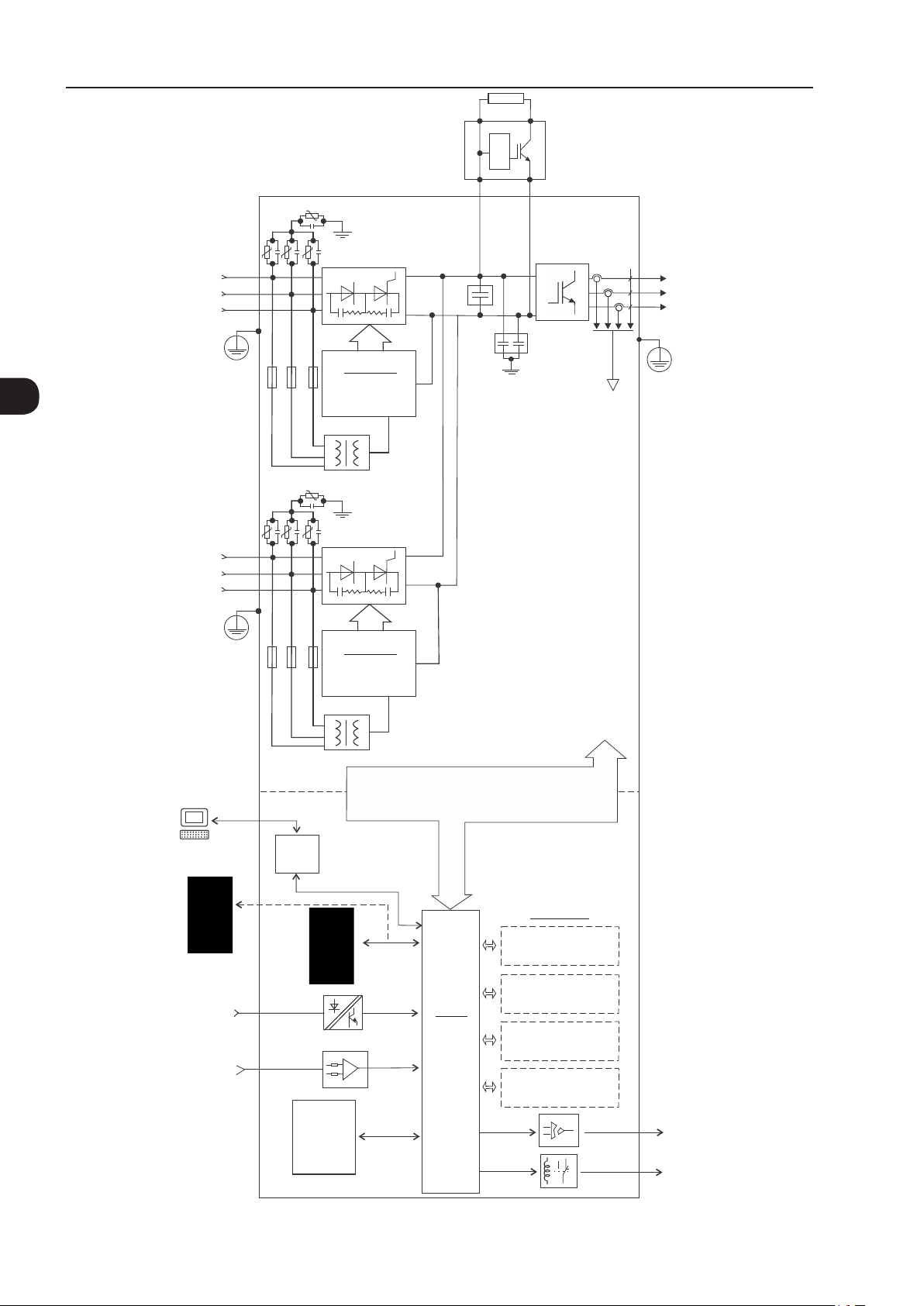
2
General Instructions
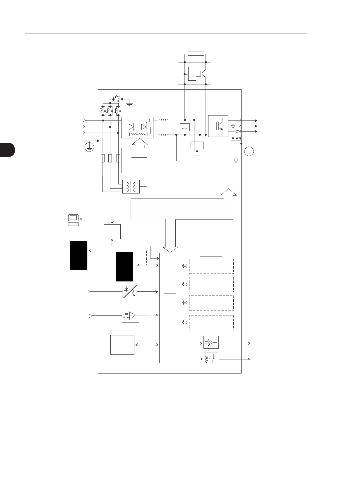
R/L1
Power supply
PC
S/L2
T/L3
PE
RFI filter/MOVs
Three-phase
rectifier
Pre-
charge
(*)
DC Link
chokes
capacitor bank
DC+ DC-BR
DC Link
Power
Control
RFI filter
= DC bus connection
= braking resistor connection
U/T1
V/T2
Motor
W/T3
Inverter
with IGBT
(*)
transistors
PE
Feedback:
- voltage
- current
SuperDrive G2 software
WLP software
Keypad (remote)
Digital inputs
(DI1 to DI6)
Analog inputs
(AI1 and AI2)
(*) The capacitor of RFI filter and MOV connected to the ground must be disconnected with IT network, high impedance grounding network and cornergrounded delta networks. Refer to item Item 3.2.3.1.2 IT Networks on page 3-35.
Figure 2.1 - Block diagram for the CFW -11 - frame sizes B and C
USB
FLASH
memory
module
MMF-03
Control power supply and interfaces
between power and control
Keypad
CC11
Control
board with
a 32 bits
"RISC"
CPU
Encoder interface
(anybus) (Slot 4 )
Accessories
I/O expansion
(Slot 1 - white)
(Slot 2 - yellow)
COMM 1
(Slot 3 - green)
COMM 2
Analog outputs
(AO1 and AO2)
Digital outputs
DO1 (RL1) to
DO3 (RL3)
2-6 | CFW-11
Page 17
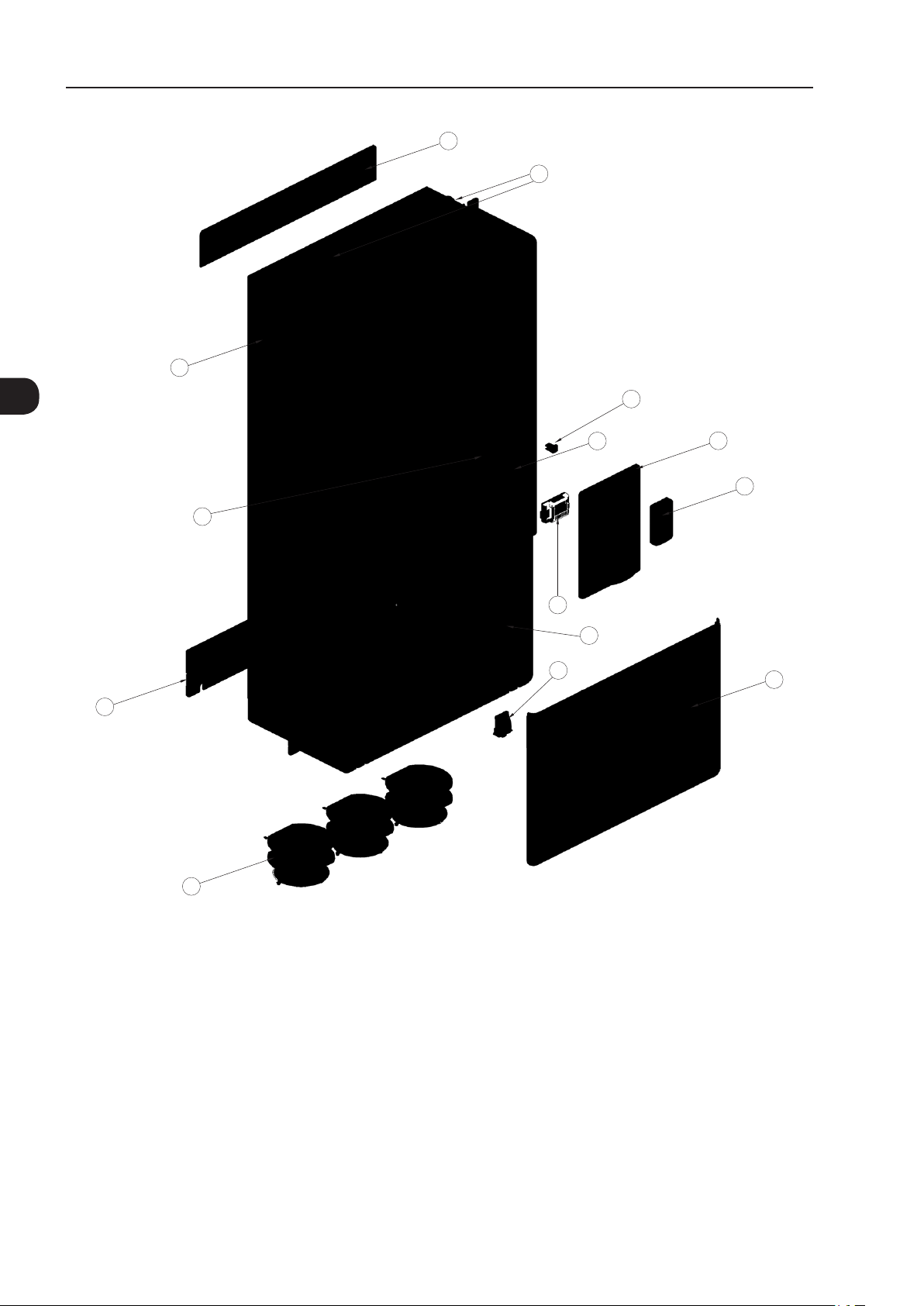
General Instructions
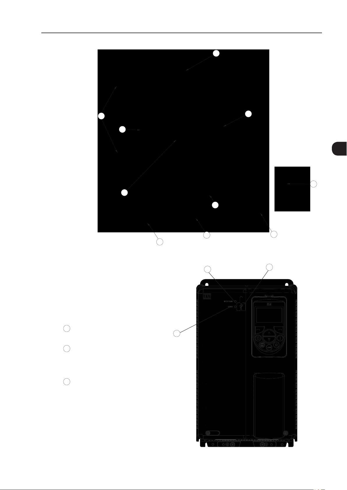
C
A
A - mounting supports
(for through the wall mounting)
B - heatsink
C - top cover
D - fan with mounting support
E - COMM 2 module (anybus)
F - option board/accessory module
G - FLASH memory module MMF-03
H - front cover
I - keypad
J - SRB2A safety stop board
Figure 2.2 - Main components of the CFW-11 - frame sizes B and C
G
B
2
I
J
F
E
D
3
H
1
USB connector
1
USB LED
2
Off: no USB connection
On/Flashing: USB communication is active
3
STATUS LED
Green: normal operation with no fault or alarm
Yellow: alarm condition
Flashing red: fault condition
Figure 2.3 - LEDs and USB connector
2
CFW-11 | 2-7
Page 18

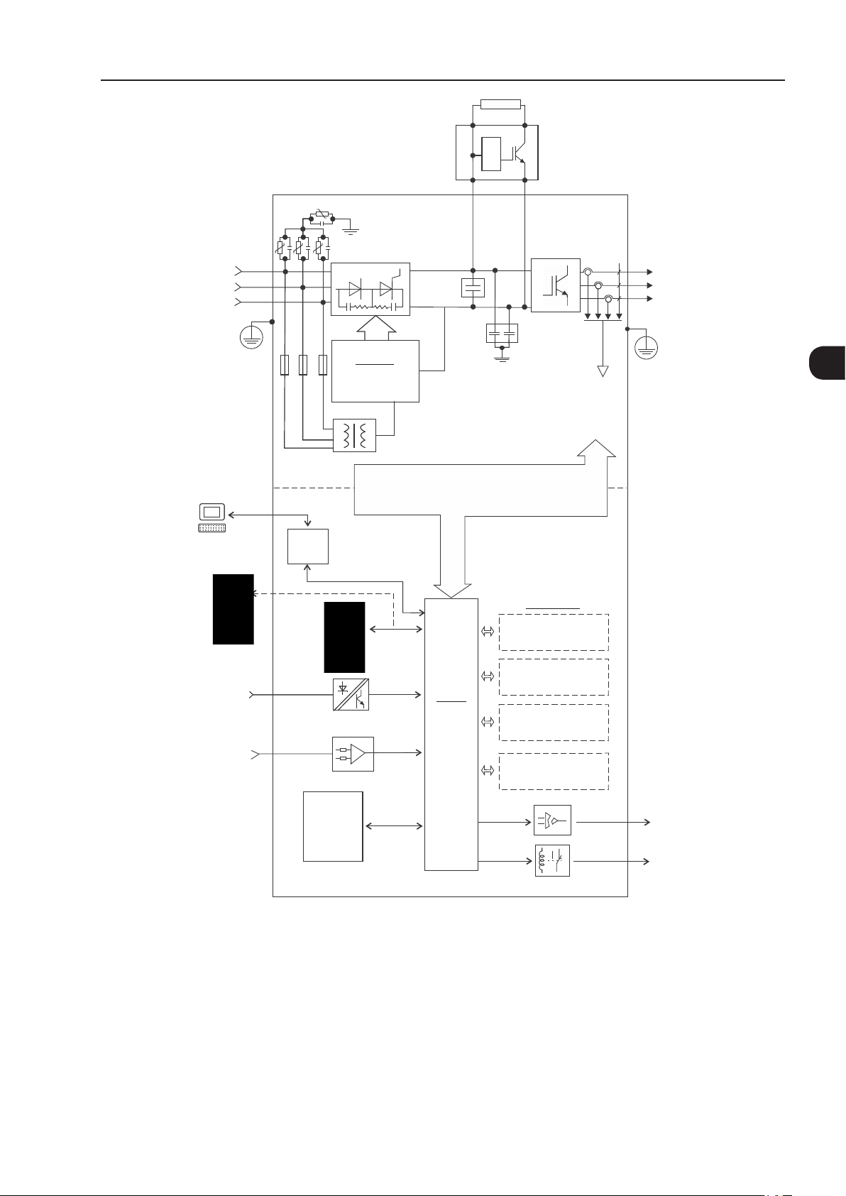
2
General Instructions
R/L1
Power supply
PC
S/L2
T/L3
PE
RFI filter/MOVs
Three-phase
rectifier
Pre-
charge
(*)
DC Link
chokes
capacitor bank
DC+ DC-BR
DC Link
Power
Control
RFI filter
= DC bus connection
= braking resistor connection
U/T1
V/T2
Motor
W/T3
Inverter
with IGBT
transistors
PE
Feedback:
- voltage
- current
SuperDrive G2 software
WLP software
Keypad (remote)
Digital inputs
(DI1 to DI6)
Analog inputs
(AI1 and AI2)
(*) The capacitor of RFI filter and MOV connected to the ground must be disconnected with IT network, high impedance grounding network and corner-
-grounded delta networks. Refer to Item 3.2.3.1.2 IT Networks on page 3-35.
Figura 2.4 - Block diagram for the CFW -11 - frame sizes D and E
USB
FLASH
memory
module
MMF-03
Control power supply and interfaces
between power and control
Keypad
CC11
Control
board with
a 32 bits
"RISC"
CPU
Encoder interface
(anybus) (Slot 4 )
Accessories
I/O expansion
(Slot 1 - white)
(Slot 2 - yellow)
COMM 1
(Slot 3 - green)
COMM 2
Analog outputs
(AO1 and AO2)
Digital outputs
DO1 (RL1) to
DO3 (RL3)
2-8 | CFW-11
Page 19

General Instructions
I
D
L
J
E
C
B
K
2
A
F
H
G
Inverter with Nema1 kit
(option - only frame size E)
I
M
A - keypad
B - control rack cover
C - CC11 control board
D - FLASH memory module MMF-03
E - control accessory module (refer to the Section 7.2 ACCESSORIES on page 7-2)
F - Anybus-CC accessory module (refer to the Section 7.2 ACCESSORIES on page 7-2)
G - bottom front cover
H - heatsink fan
I - mounting supports (for through the wall mounting)
J - hoisting eye
K - rear part of the inverter (external part for flange mounting)
L - SRB4 safety stop board
M - Nema1 kit - only frame size E
Figure 2.5 - Main components of the CFW-11 - frame sizes D and E
CFW-11 | 2-9
Page 20
General Instructions
Power
supply
R/L1
S/L2
T/L3
RFI filter/MOVs
Three-phase
rectifier
External braking
module
(Optional)
(*)
DC+
Braking
resistor
DC-
U/T1
V/T2
W/T3
Motor
2
PE
PC
SuperDrive G2 software
WLP software
Keypad (remote)
Digital inputs
(DI1 to DI6)
Analog inputs
(AI1 and AI2)
Power
Control
USB
chokes
CPC 11
Pre-charge
control
Keypad
DC Link
Control power supply and interfaces
between power and control sections
CC11
Control
board with
32-bit
"RISC"
CPU
bank
DC link capacitor
Encoder interface
IGBT
inverter
RFI filter
Accessories
I/O expansion
(Slot 1 - white)
(Slot 2 - yellow)
COMM 1
(Slot 3 - green)
COMM 2
(anybus) (Slot 4)
PE
Feedback:
- voltage
- current
FLASH
memory
module
MMF-03
(*) The capacitor of RFI filter and MOV connected to the ground must be disconnected with IT network, high impedance grounding network and cornergrounded delta networks. Refer to Item 3.2.3.1.2 IT Networks on page 3-35.
(a) Frame sizes F and G CFW-11 block diagram - Standard models with alternating current feeding
Analog outputs
(AO1 and AO2)
Digital outputs
DO1 (RL1) to
DO3 (RL3)
2-10 | CFW-11
Page 21

DC supply
General Instructions
PC
SuperDrive G2 software
WLP software
Keypad (remote)
Digital inputs
(DI1 to DI6)
Analog inputs
(AI1 and AI2)
Power
Control
USB
DC+
DC Link capacitor bank
Control power supply and interfaces
between power and control sections
Keypad
CC11
CC11
Control
board with
32-bit
"RISC" CPU
DC-
IGBT
inverter
Feedback:
- voltage
RFI filter
Accessories
I/O expansion
(Slot 1 - white)
Encoder interface
(Slot 2 - yellow)
COMM 1
(Slot 3 - green)
(anybus) (Slot 4)
- current
COMM 2
U/T1
V/T2
W/T3
PE
Motor
2
FLASH
memory
module
MMF-03
(b) Frame sizes F and G CFW-11 block diagram - Models with DC voltage feeding (Special DC Hardware)
Figure 2.6 - (a) and (b) - Block diagram for the CFW-11 - frame sizes F and G
Analog outputs
(AO1 and AO2)
Digital outputs
DO1 (RL1) to
DO3 (RL3)
CFW-11 | 2-11
Page 22

2
General Instructions
K
I
J
D
C
L
B
A
I
H
A - keypad
B - control rack cover
C - CC11 control board
D - FLASH memory module MMF-03
E - control accessory module
F - Anybus-CC accessory module
G - bottom front cover
H - bheatsink fan
I - mounting supports (for surface mounting)
J - hoisting eye
K - rear part of the inverter (external part for flange mounting)
L - SRB3 safety stop board
E
F
G
2-12 | CFW-11
Figure 2.7 - CFW-11 main components - frame sizes F and G
Page 23
External braking
module
(Accessory)
General Instructions
Braking
resistor
Power
supply
SuperDrive G2 software
WLP software
R/L1
S/L2
T/L3
PE
PC
RFI filter/MOVs
Three-phase
Rectifier
Pre-charge
Power
Control
USB
(*)
CPC 11
control
Control power supply and interfaces
between power and control sections
DC+
RFI filter
DC Link capacitor bank
DC-
IGBT
inverter
Feedback:
- voltage
- current
U/T1
V/T2
W/T3
PE
Motor
2
Accessories
I/O expansion
(Slot 1 - white)
Keypad (remote)
Digital inputs
(DI1 to DI6)
Analog inputs
(AI1 and AI2)
FLASH
memory
module
MMF-03
(*) The RFI filter capacitor and MOV connected to the ground must be disconnected with IT and corner-grounded delta networks. Refer to Item 3.2.3.1.2
IT Networks on page 3-35.
Figure 2.8 - Block diagram of standard models of CFW-11 frame size H (584 A and 625 A models) with alternating current
Keypad
CC11
Control
board with
32-bit
"RISC" CPU
feeding
Encoder interface
(Slot 2 - yellow)
COMM 1
(Slot 3 - green)
COMM 2
(anybus) (Slot 4)
Analog outputs
(AO1 and AO2)
Digital outputs
DO1 (RL1) to
DO3 (RL3)
CFW-11 | 2-13
Page 24
2
General Instructions
R1/L1-1
Power
S1/L2-1
supply
T1/L3-1
PE
RFI filter/MOVs
Three-phase
rectifier
CPC 11-1
Pre-charge
External braking
module
(Accessory)
(*)
control
Braking resistor
DC+
DC Link capacitor bank
DC-
IGBT
inverter
RFI filter
Feedback:
- voltage
- current
U/T1
V/T2
W/T3
Motor
PE
RFI filter/MOVs
R2/L1-2
Power
S2/L2-2
supply
T2/L3-2
PE
Power
PC
SuperDrive G2 software
WLP software
Keypad (remote)
Digital inputs
(DI1 to DI6)
Analog inputs
(AI1 and AI2)
(*) The capacitor of RFI filter and MOV connected to the ground must be disconnected with IT network, high impedance grounding network and
corner-grounded delta networks. Refer to Item 3.2.3.1.2 IT Networks on page 3-35.
Figure 2.9 - Block diagram of standard models of CFW-11 frame size H (758 A and 804 A models) with alternating current
Control
USB
FLASH
memory
module
MMF-03
(*)
Three-phase
rectifier
CPC 11-2
Pre-charge
control
Keypad
Control power supply and interfaces
between power and control sections
Accessories
I/O expansion
(Slot 1 - white)
Encoder interface
CC11
Control
board with
32-bit
"RISC" CPU
(Slot 2 - yellow)
COMM 1
(Slot 3 - green)
COMM 2
(anybus) (Slot 4)
Analog outputs
(AO1 and AO2)
Digital outputs
DO1 (RL1) to
DO3 (RL3)
2-14 | CFW-11
Page 25

DC power supply
General Instructions
PC
SuperDrive G2 software
WLP software
Keypad (remote)
Digital inputs
(DI1 to DI6)
Analog inputs
(AI1 and AI2)
Power
Control
USB
DC+
DC Link capacitor bank
Control power supply and interfaces
between power and control sections
Keypad
CC11
Control
board with
32-bit
"RISC" CPU
DC-
RFI filter
IGBT
inverter
Feedback:
- voltage
- current
Accessories
I/O expansion
(Slot 1 - white)
Encoder interface
(Slot 2 - yellow)
COMM 1
(Slot 3 - green)
COMM 2
(anybus) (Slot 4)
U/T1
V/T2
W/T3
Motor
PE
2
FLASH
memory
module
MMF-03
Figure 2.10 - Block diagram of CFW-11 frame size H models with DC voltage feeding (special hardware DC)
Analog outputs
(AO1 and AO2)
Digital outputs
DO1 (RL1) to
DO3 (RL3)
CFW-11 | 2-15
Page 26
General Instructions
K
I
J
2
D
C
L
E
M
F
I
B
A
G
H
A - keypad
B - control rack cover
C - CC11 control board
D - FLASH memory module MMF-03
E - control accessory module
F - Anybus-CC accessory module
G - bottom front cover
H - heatsink fan
I - mounting supports (for surface mounting)
J - hoisting eye
K - rear part of the inverter (external part for flange mounting)
L - SRB3 safety stop board
M - shield for the control cables
Figure 2.11 - CFW-11 main components - frame size H
2-16 | CFW-11
Page 27
General Instructions
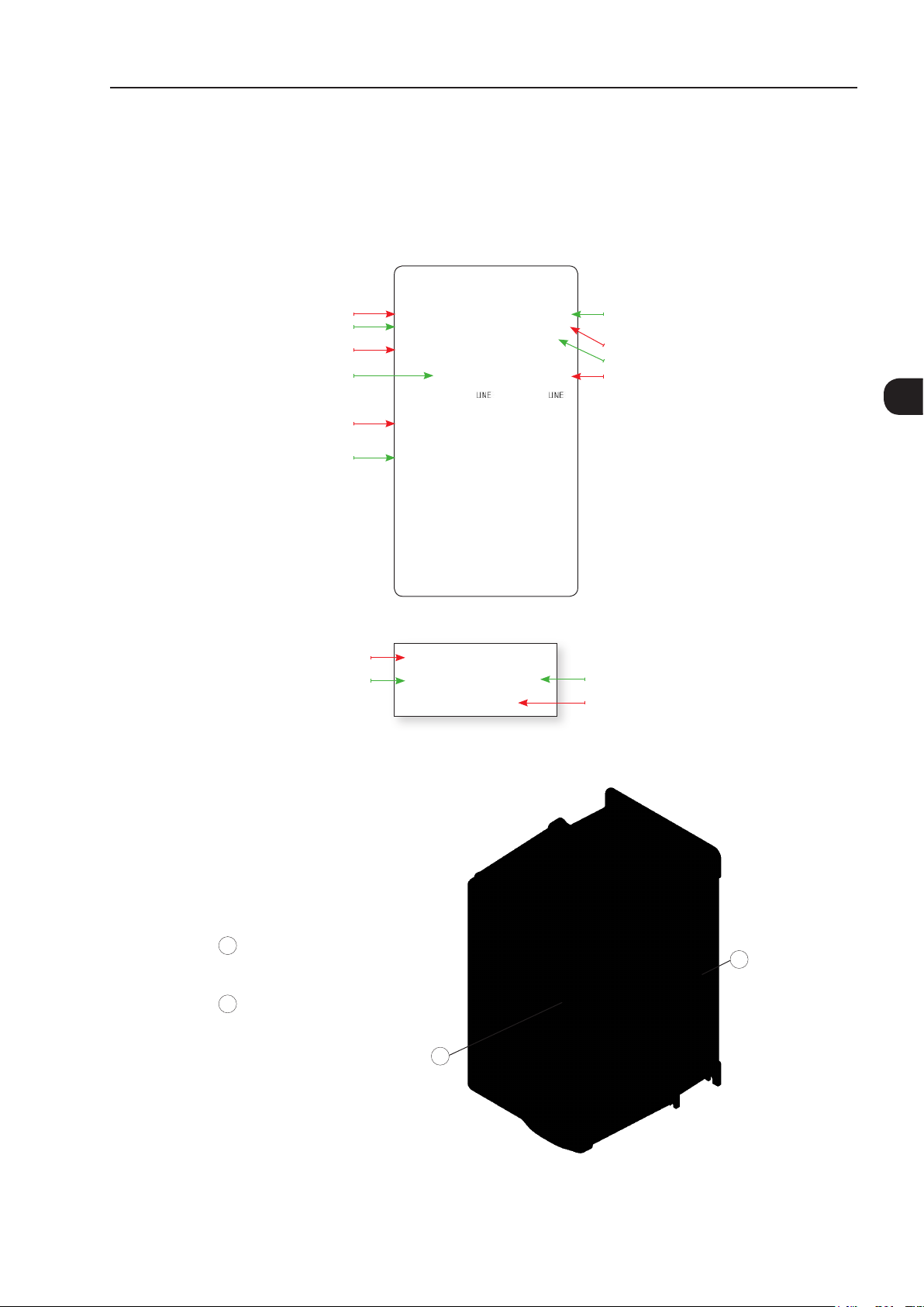
2.4 IDENTIFICATION LABELS FOR THE CFW-11
There are two nameplates on the CFW-11: one complete nameplate is affixed to the side of the inverter and
a simplified one is located under the keypad. The nameplate under the keypad allows the identification of the
most important characteristics of the inverter even if they are mounted side-by-side.
CFW-11 model
WEG part number
Inverter net weight
Rated input data (voltage, number of phases,
rated currents for operation with ND and HD
overload cycles, frequency)
Current specifications for operation with
normal overload cycle (ND)
Current specifications for operation with
heavy overload cycle (HD)
CFW-11 model
WEG part number
Manufacturing date (48 corresponds
to week and H to year)
Serial number
Maximum surrounding air temperature
Rated output data (voltage, number of phases,
rated currents for operation with ND and HD
overload cycles, over load currents for 1 min
and 3 s, frequency range)
(a) Nameplate afxed to the side of the inverter
BRCFW110044T6OYZ
11799018
SERIAL#:
(b) Nameplate located under the keypad
Figure 2.12 - (a) and (b) - Nameplates
1013933619
48 H
Manufacturing date
(48 corresponds to
week and H to year)
Serial number
2
Nameplate affixed to the side of the
1
heatsink
Nameplate under the keypad
2
Figure 2.13 - Location of the nameplates
1
2
CFW-11 | 2-17
Page 28

General Instructions
2
Character
that
identifies
the code
end
Special
software
Special
hardware
power supply for
control
Blank =
standard
E.g.:
S1 =
Blank =
standard
DC= feeding
with DC (only
Blank =
standard (not
available)
W = 24 Vdc
Blank =
standard (Safety
Stop function is
not available)
Blank =
standard
internal
RFI filter
(3)
NB =
without
Blank =
standard
special
software #1
valid for frame
sizes F and G)
H1 = special
hardware #1
external power
supply for control
Y = Safety
Stop according
to EN-954-1
category 3
(5)
NF =
without
RFI filter
(4)
braking
IGBT
(2)
IC = no
keypad
Blank =
standard
(6)
(7)
(1)
N1 = Nema1
Refer to Chapter 7 OPTION KITS AND ACCESSORIES on page 7-1, to check option kit availability for each inverter model
Option kit Enclosure type Keypad (HMI) Braking RFI filter Safety stop 24 Vdc external
Power supply
voltage
Number of
power phases
21 = IP21
Blank =
standard
S =
standard
product
O =
(8)
(9)
6 = 500...690 V
5 = 500...600 V
T = three-
phase power
supply
Inverter Model Available Option Kits (Can Be Installed in the Product from the Factory)
Rated
output
current for
use with
the Normal
Duty (ND)
cycle
According
Table 8.1
on page
8-2 and
(blind cover)
product
with option
kit
Table 8.3
on page
8-4
Refer to Chapter 8 TECHNICAL SPECIFICATIONS on page
8-1, for a list of models for the CFW-11 series and for a
complete inverter's technical specification
HOW TO CODIFY THE CFW-11 MODEL (CODIFICATION)
2-18 | CFW-11
Example BR CFW11 0044 T 6 S _ _ _ _ _ _ _ _ _ _ _ _ _ _ _ _ Z
WEG
Market
Field
CFW-11
frequency
inverter
series
identification
(defines
the manual
language and
description
the factory
settings)
2 characters
Available
options
(1) Standard for frame sizes B and C: IP21.
Standard for frame size D: IP20/NEMA1.
Standard for frame sizes E, F, G and H: IP20.
Standard for frame sizes F, G and H with special hardware DC: IP00.
(2) Standard keypad (HMI-CFW11).
(3)Braking transistor (IGBT) is incorporated in all models of frame sizes B, C, D, and E as standard.
(4) Only valid for frame sizes D and E.
(5) Only valid for frame sizes B, C and D.
(6) Only valid for frame sizes B, C, D and E.
(7) Only valid for frame sizes D, E, F and G.
(8) Only valid for frame sizes B and C.
(9) Only valid for frame sizes D, E, F, G and H.
Page 29
General Instructions
2.5 RECEIVING AND STORAGE
The CFW-11 is packaged and shipped in a cardboard box for models of frames B, and C.
The frame sizes D, E, F, G and H models are supplied packed in wooden boxes.
There is an identification label affixed to the outside of the package, identical to the one affixed to the side of
the inverter.
To open the package:
1. Remove the package front cover.
2. Take out the polystyrene foam protection.
Verify whether:
1. The CFW-11 nameplate corresponds to the purchased model.
2. Any damage occurred during transportation.
Report any damage immediately to the carrier that delivered your CFW-11 inverter.
If the CFW-11 is not installed soon, store it in a clean and dry location (temperature between -25 °C and 60 °C
(-13 °F and 140 °F), with a cover to prevent dust accumulation inside it.
ATTENTION!
When the inverter is stored for a long period, it becomes necessary to perform the capacitor reforming.
Refer to the procedure in the Section 6.5 PREVENTIVE MAINTENANCE on page 6-9 in the Table
6.3 on page 6-9.
2
CFW-11 | 2-19
Page 30

2
General Instructions
2-20 | CFW-11
Page 31

3 INSTALLATION AND CONNECTION
This chapter provides information on installing and wiring the CFW-11.
The instructions and guidelines listed in this manual shall be followed
to guarantee personnel and equipment safety, as well as the proper
operation of the inverter.
3.1 MECHANICAL INSTALLATION
3.1.1 Installation Environment
NOTE!
The inverter are designed for indoor use only.
Avoid:
Installation and Connection
Direct exposure to sunlight, rain, high humidity, or sea-air.
Inflammable or corrosive gases or liquids.
Excessive vibration.
Dust, metallic particles, and oil mist.
Environment conditions for the operation of the inverter:
Temperature (standard conditions (surrounding the inverter), no frost allowed):
- 10 ºC to 50 ºC (14 ºF to 122 ºF) for frame sizes B, C and D models.
- 10 ºC to 45 ºC (14 ºF to 113 ºF) for frame sizes E, F and G models.
- 10 ºC to 40 ºC (14 ºF to 104 ºF) for frame size H.
From 40 ºC to 45 ºC (104 ºF to 113 ºF) for frame size H: 1 % of current derating for each Celsius degree
above maximum temperature as specified in item above.
From 50 ºC to 60 ºC (122 °F to 140 °F) for frame sizes B, C and D models and from 45 ºC to 55 ºC (113
ºF to 131 ºF) for frame sizes E, F, G and H models: 2 % of current derating for each Celsius degree above
maximum temperature as specified in item above.
3
Altitude: up to 1000 m (3.300 ft) above sea level - standard conditions (no derating required).
From 1000 m to 4000 m (3.300 ft to 13.200 ft) above sea level - 1 % of current derating for each 100 m
(330 ft) above 1000 m (3.300 ft) altitude.
CFW-11 | 3-1
Page 32

Installation and Connection
From 2000 m to 4000 m (6.600 ft to 13.200 ft) above sea level - reduction of maximum voltage (600 V for
500...600 V models and 690 V for 500...690 V models) of 1.1 % for each 100 m (330 ft) above 2000 m
(6.600 ft).
Note that derating specified in items above applies also to dynamyc braking IGBT (columm effective braking
current (I
Humidity: from 5 % to 95 % non-condensing.
Pollution degree: 2 (according to EN50178 and UL508C) with non-conductive pollution. Condensation
shall not originate conduction through the accumulated residues.
) of Table 3.10 on page 3-40).
effective
3.1.2 Mounting Considerations
Consult the inverter weight at the Table 8.1 on page 8-2, Table 8.2 on page 8-3, Table 8.3 on page 8-4
and Table 8.4 on page 8-5.
3
Mount the inverter in the upright position on a flat and vertical surface.
External dimensions and fixing holes position according to the Figure 3.1 on page 3-3, Figure 3.2 on page
3-4 and Figure 3.2 on page 3-4. Refer to the Section 8.5 MECHANICAL DATA on page 8-9, for more
details.
First mark the mounting points and drill the mouting holes. Then, position the inverter and firmly tighten the
screws in all four corners to secure the inverter.
Minimum mounting clearances requirements for proper cooling air circulation are specified in Figure 3.3 on page
3-5, Figure 3.5 on page 3-9 and Figure 3.4 on page 3-6.
Inverters of frame sizes B and C can be arranged side-by-side with no clearance required between them. In this
case, the top cover must be removed as shown in Figure 3.3 on page 3-5.
Do not install heat sensitive components right above the inverter.
ATTENTION!
When arranging two or more inverters vertically, respect the minimum clearance A + B (Figure 3.3 on
page 3-5, Figure 3.5 on page 3-9 and Figure 3.4 on page 3-6) and provide an air deflecting
plate so that the heat rising up from the bottom inverter does not affect the top inverter.
ATTENTION!
3-2 | CFW-11
Provide conduit for physical separation of the signal, control, and power conductors (refer to Section
3.2 ELECTRICAL INSTALLATION on page 3-14).
Page 33

Installation and Connection
B1
b2
A1
E1
(a) Dimension external
a2
C1
D1
a3
3
b3c3
e3
Air flow
(b) Montagem em superfície (c) Montagem em ange
A1 B1 C1 D1 E1 a2 b2 c2 a3 b3 c3 d3 e3 f3 Torque
Model
Frame
Size B
Frame
Size C
Frame
Size D
Tolerances for dimensions d3 and e3: +1.0 mm (+0.039 in).
Tolerances for remaining dimensions: ±1.0 mm (±0.039 in).
(*) Recommended torque for the inverter mounting (valid for c2 and f3).
mm
(in)mm(in)mm(in)
190
(7.48)
220
(8.67)
300
(11.81)
293
(11.53)
378
(14.88)
504
(19.84)
mm
(in)mm(in)mm(in)mm(in)
227
(8.94)71(2.79)
293
(11.52)
305
(12.00)
Figure 3.1 - (a) to (c) - Mechanical installation details - frame sizes B, C and D
136
(5.36)
135
(5.32)
∅ c2
316
(12.44)
405
(15.95)
550
(21.65)
150
(5.91)
150
(5.91)
200
(7.88)
300
(11.81)
375
(14.77)
525
(20.67)
Air flow
M
M5
M6
M8
mm
(in)
175
(6.89)
195
(7.68)
275
(10.83)
Max. 3 mm
(0.12 in)
mm
(in)mm(in)mm(in)mm(in)
255
(10.04)
142.5
(5.61)
182.5
(7,18)
262
(10.31)
180
(7.09)
206
(8.11)
287
(11.30)
d3
∅ c3
272
(10.71)
346
(13.62)
487
(19.17)
M
M5
M6
M8
N.m
(lbf.in)
5.0
(44.2)
8.5
(75.2)
20.0
(177.0)
(*)
CFW-11 | 3-3
Page 34

Installation and Connection
A1
B1
C1
3
B1
a2 a2
a2 a2
A1
E1
E1
(a) Dimension external
D1
C1
a3
a3
b2
b2
∅ c2
Air flow Air flow
(b) Surface mounting (c) Flange mounting
A1 B1 C1 D1 E1 a2 b2 c2 a3 b3 c3 d3 e3
Model
Frame
Size E
Frame
Size F
Frame
Size G
Frame
Size H
Tolerance for dimensions d3 and e3: +1.0 mm (+0.039 in).
Tolerance for remaining dimensions: ±1.0 mm (±0.039 in).
mm
(in)
335
(13.2)
430
(16.93)
535
(21.06)
686.0
(27.00)
mm
(in)
375
(26.6)
1156
(45.51)
1190
(46.85)
1319.7
(51.96)
mm
(in)
358
(14.1)
360
(14.17)
426
(16.77)
420.8
(16.57)
mm
(in)
168 (6.6)
169
(6.65)
202
(7.95)
171.7
(6.76)
(48.58)
(49.76)
1414.0
(55.67)
Figure 3.2 - (a) to (c) - Mechanical installation details - frame sizes E, F, G and H
c2
mm
(in)
620
(24.4)
1234
1264
mm
(in)
200 (7.8)
150
(5.91)
200
(7.87)
175.0
(6.89)
mm
(in)
650
(25.6)
1200
(47.24)
1225
(48.23)
1350.0
(53.15)
Max. 3 mm
Max. 3mm (0.12)
(0.12)
M
M8
M10
M10
M10
mm
(in)
275
(10.8)
350
(13.78)
400
(15.75)
595.0
(23.43)
b3
b3
d3
d3
c3
∅ c3
mm
(in)
M
635 (25) M8
1185
(46.65)
1220
(48.03)
1345.0
(52.95)
M10
M10
M10
e3
e3
mm
(in)
315
(24.21)
391
(15.39)
495
(19.49)
647.0
(25.47)
mm
(in)
615
(24.21)
1146
(45.12)
1182
(46.53)
1307.0
(51.46)
3-4 | CFW-11
Page 35

Installation and Connection
A
B
(a) Minimum top, bottom, and front clearance requirements for air circulation
(1.18) 30 (1.18) 30
C
A B C
Model
Frame
Size B
Frame
Size C
Frame
Size D
Tolerance: ±1.0 mm (±0.039 in)
mm
(in)
40
(1.57)45(1.77)10(0.39)
110
(4.33)
110
(4.33)
mm
(in)
130
(5.12)10(0.39)
130
(5.12)10(0.39)
mm
(in)
3
* Dimensions in mm [in]
(b) Minimum side clearance requirements
(c) Only frame sizes B and C: side-by-side mounting - No clearance required between inverters if top cover is removed
Figure 3.3 - (a) to (c) - Free spaces around inverter for ventilation - frame sizes B, C and D
CFW-11 | 3-5
Page 36

Installation and Connection
D D
A
AB
3
C
B
C
3-6 | CFW-11
D D
A B C D
Model
Frame Sizes
E, F, G and H
Tolerance: ±1.0 mm (±0.039 in).
Figure 3.4 - Free spaces around inverter for ventilation - frame sizes E, F, G and H
mm
(in)
150
(5.91)
mm
(in)
250
(9.84)
mm
(in)
20
(0.78)
mm
(in)
80
(3.15)
Page 37

Installation and Connection
3.1.3 Cabinet Mounting
There are two possibilities for mounting the inverter: through the wall mounting or flange mounting (the heatsink
is mounted outside the cabinet and the cooling air of the power module is kept outside the enclosure). The
following information shall be considered in these cases:
Surface Mounting:
Provide adequate exhaustion so that the internal cabinet temperature is kept within the allowable operating
range of the inverter.
The power dissipated by the inverter at its rated condition, as specified in Table 8.1 on page 8-2 to Table
8.4 on page 8-5 "Dissipated power in Watts - through the wall mounting".
The cooling air flow requirements, as shown in Table 3.1 on page 3-8.
The position and diameter of the mounting holes, according to Figure 3.1 on page 3-3, Figure 3.2 on
page 3-4 and Figure 3.2 on page 3-4.
Flange Mounting:
Frame Sizes B, C and D:
The losses specified in Table 8.1 on page 8-2 and Table 8.3 on page 8-4 "Dissipated power in Watts -
flange mounting" will be dissipated inside the cabinet. The remaining losses (power module) will be dissipated
through the vents.
The mounting supports shall be removed and repositioned as illustrated in Figure 3.5 on page 3-9.
The portion of the inverter that is located outside the cabinet is rated IP54. Provide an adequate gasket for
the cabinet opening to ensure that the enclosure rating is maintained. Example: silicone gasket.
Mounting surface opening dimensions and position/diameter of the mounting holes, as shown in Figure 3.1
on page 3-3.
Frame Size E:
3
The losses specified in Table 8.1 on page 8-2 and Table 8.3 on page 8-4 "Dissipated power in Watts -
flange mounting" will be dissipated inside the cabinet. The remaining losses (power module) will be dissipated
through the vents.
The inverter securing supports (position I of Figure 2.5 on page 2-9) and the hoisting eyes (position J of
Figure 2.5 on page 2-9) must be removed and repositioned according to the Figure 3.6 on page 3-10
and Figure 3.7 on page 3-10.
For models 53 A, 63 A, 80 A and 107 A, the portion of the inverter that is located outside the cabinet
is rated IP54. Provide an adequate gasket for the cabinet opening to ensure that the enclosure rating is
maintained. Example: silicone gasket.
CFW-11 | 3-7
Page 38

3
Installation and Connection
Mounting surface opening dimensions and position/diameter of the mounting holes, as shown in Figure 3.2
on page 3-4.
Frame Sizes F, G and H:
ATTENTION!
The part of the inverter that stays outside the cabinet is rated IP20.
The power specified in Table 8.1 on page 8-2 to Table 8.4 on page 8-5 under "Dissipated power in
Watts - flange mounting" will be dissipated inside the cabinet. Use Table 8.1 on page 8-2 and Table 8.3
on page 8-4 for inverters with AC power supply and Table 8.2 on page 8-3 and Table 8.4 on page
8-5 for inverters with DC power supply. The other losses (power modules) will be dissipated at the external
ventilation duct.
The inverter mounting supports and the hoisting eyes must be removed. Refer to the Figure 3.8 on page
3-11, positions I and J.
Dimensions of the flange-mounting opening and the diameters of the securing holes must be according to
the Figure 3.2 on page 3-4.
Table 3.1 - Minimum required cabinet cooling air ow
Frame Size CFM I/s m³/min
B 42 20 1.2
C 96 45 2.7
D 132 62 3.7
E 265 125 7.5
F 460 217 13
G 680 321 19.3
H 1100 520 31.2
3-8 | CFW-11
Page 39

Installation and Connection
321
654
3
Figure 3.5 - Repositioning the mounting supports - frame sizes B, C and D
CFW-11 | 3-9
Page 40

Installation and Connection
3
21
3
654
Figure 3.6 - Repositioning the mounting supports - frame size E
3.1.4 Installation of the Inverter Hoisting Eyes - Frame Size E
Two hoisting eyes for the inverter lifting, which are mounted at the inverter sides (rear part), are supplied. By
inverting their position, as shown in Figure 3.7 on page 3-10, two points for hoisting the inverter, which are
very useful during the mechanical installation of the inverter, are obtained.
3-10 | CFW-11
Figure 3.7 - Installation of the inverter hoisting eyes frame size E
Page 41

Installation and Connection
3.1.5 Installation of the Inverter with Nema1 Kit (Option, CFW11....T...ON1...) on a Wall -
Frame Size E
Fixing holes position and diameter according to the Figure 3.2 on page 3-4 for frame size E models.
External dimensions of the inverter with Nema1 kit according to Section 8.6 NEMA 1 KITs on page 8-16.
Fasten the inverter.
Install the Nema1 kit on the inverter as shown in Figure 3.8 on page 3-11 using the two M8 screws supplied
with the product.
3
Figure 3.8 - Installation of the Nema1 kit in frame size E model
3.1.6 Access to the Control and Power Terminal Strips
Frame Sizes B and C:
It is necessary to remove the keypad and the front cover in order to get access to the control and power terminal
strips.
321
Figure 3.9 - Removal of keypad and front cover - frame sizes B and C
CFW-11 | 3-11
Page 42

Installation and Connection
Frame Sizes D and E:
It is necessary to remove the keypad (HMI) and the control rack cover in order to get access to the control
terminal strip (see Figure 3.10 on page 3-12). In order to get access to the power terminal strip, remove the
bottom front cover (see Figure 3.11 on page 3-12).
1 2 3
3
Figure 3.10 - HMI and control rack cover removal - frame sizes D and E
1 2
Figure 3.11 - Bottom front cover removal - frame sizes D and E
3-12 | CFW-11
Page 43

Installation and Connection
Frame Sizes F, G and H:
In order to get access to the control terminals, it is necessary to remove the HMI and the control rack cover, as
showed in Figure 3.12 on page 3-13.
1 2 3
Figure 3.12 - Removal of the HMI and the control rack cover - frame sizes F, G and H
In order to get access to the power terminals, it is necessary to remove the bottom front cover, as shown in
Figure 3.13 on page 3-13.
1 2
Figure 3.13 - Removal of the bottom front cover, to access to the power supply and motor connection terminals -
frame sizes F, G and H
In order to connect the power cables (line and motor), remove the bottom plate, as shown in Figure 3.14 on
page 3-13. In this case the protection degree of the inverter bottom part will be reduced.
3
Figure 3.14 - Removal of the bottom plate, to access the power terminals - frame sizes F, G and H
CFW-11 | 3-13
Page 44

Installation and Connection
3.1.7 Removal of the Cable Passage Plate - Frame Sizes D and E
When it is not necessary neither IP20 nor Nema1 protection degree, the cable passage plate may be removed
in order to make the inverter electric installation easier. Remove the four M4 screws, according to the procedure
presented in Figure 3.15 on page 3-14.
3
1
2
3
Figure 3.15 - Removal of the cable passage plate - frame sizes D and E
3.1.8 HMI Installation at the Cabinet Door or Command Panel (Remote HMI)
28.5 [1.12]
23.5
[0.93]
113.0 [4.45]
65.0 [2.56]
35.0 [1.38]
103.0 [4.06]
23.4 [0.92]
16.0 [0.63]
∅4.0 [0.16] (3X)
Figure 3.16 - Data for the HMI installation at the cabinet door or command panel - mm [in]
The keypad frame accessory can also be used to fix the HMI, as mentioned in Table 7.1 on page 7-3.
3.2 ELECTRICAL INSTALLATION
DANGER!
The following information is merely a guide for proper installation. Comply with applicable local
regulations for electrical installations.
3-14 | CFW-11
Page 45
DANGER!
Les informations suivantes constituent uniquement un guide pour une installation correcte. Respectez
les réglementations locales en vigueur pour les installations électriques.
DANGER!
Make sure the AC power supply is disconnected before starting the installation.
DANGER!
Vérifiez que l'alimentation secteur CA est débranchée avant de commencer l'installation.
ATTENTION!
Integral solid state short circuit protection does not provide branch circuit protection. Branch circuit
protection must be provided in accordance with applicable local codes.
3.2.1 Identification of the Power and Grounding Terminals
Installation and Connection
3
R/L1, S/L2, T/L3: AC power supply connection.
U/T1, V/T2, W/T3: motor connection.
DC-: this is the negative potential terminal in the DC bus circuit.
BR: braking resistor connection (frame sizes B, C, D and E only).
DC+: this is the positive potential terminal in the DC bus circuit.
R/L1 S/L2 T/L3
BR
DC+DC-
U/T1
V/T2
W/T3
Figure 3.17 - Grounding and power terminals of frame sizes B and C models
Grounding
CFW-11 | 3-15
Page 46

Installation and Connection
3
R/L1 S/L2 T/L3
DC+DC-
BR
Figure 3.18 - Grounding and power terminals of frame size D models
U/T1
V/T2
W/T3
Grounding
3-16 | CFW-11
Grounding
(4xM8, 4xM5)
Figure 3.19 - Grounding and power terminals of frame size E models
Page 47

Installation and Connection
(a) Terminals for AC power supply and motor connection (terminals R/L1, S/L2 and T/L3 are not assembled in inverters with
special hardware DC)
3
DC-
DC+
(b) Terminals for DC power supply connection (only available in inverters with special hardware DC)
Figure 3.20 - (a) and (b) - Grounding and power terminals of frame size F models
CFW-11 | 3-17
Page 48

Installation and Connection
3
U/T1
R/L1
(a) Terminals for AC power supply and motor connection (terminals R/L1, S/L2 and T/L3 are not assembled in inverters with
special hardware DC)
V/T2
S/L2
DC-
W/T3
T/L3
DC+
(b) Terminals for DC power supply connection (only available in inverters with special hardware DC)
3-18 | CFW-11
Figure 3.21 - (a) and (b) - Grounding and power terminals of frame size G models
Page 49

Installation and Connection
(a) Models 584 and 625 A (b) Models 758 A and 804 A
DC-
DC+
3
(c) Frame size H
Figure 3.22 - (a) to (c) - Grounding and power terminals of frame size H models
CFW-11 | 3-19
Page 50

3
Installation and Connection
3.2.2 Power/Grounding Wiring and Fuses
ATTENTION!
Use proper cable lugs for the power and grounding connection cables.
ATTENTION!
Sensitive equipment such as PLCs, temperature controllers, and thermal couples shall be kept at a
minimum distance of 0.25 m (9.84 in) from the frequency inverter and from the cables that connect
the inverter to the motor.
DANGER!
Wrong cable connection:
- The inverter will be damaged if the power supply is connected to the output terminals (U/T1, V/T2,
or W/T3).
- Check all the connections before powering up the inverter.
- When replacing an existing inverter by a CFW-11, check if the installation and wiring is according
to the instructions listed in this manual.
DANGER!
Mauvaise connexion des câbles:
- Le variateur sera endommagé si l’alimentation d’entrée est connectée aux bornes de sortie (U/T1,
V/T2 ou W/T3).
- Vérifier toutes les connexions avant de mettre le variateur sous tension.
- En cas de remplacement d’un variateur existant par un CFW-11, vérifier si l’installation et le câblage
sont conformes aux instructions figurant dans ce manuel.
ATTENTION!
Residual Current Device (RCD):
- When installing an RCD to guard against electrical shock, only devices with a trip current of 300 mA
should be used on the supply side of the inverter.
- Depending on the installation (motor cable length, cable type, multimotor configuration, etc.), RCD
nuisance trips may occur. Contact the RCD manufacturer for selecting the most appropriate device
to be used with inverters.
NOTE!
The wire gauges listed in Table 3.2 on page 3-21 are orientative values. Installation conditions and
the maximum permitted voltage drop must be considered for the proper wiring sizing.
3-20 | CFW-11
Page 51

Installation and Connection
Input fuses:
Use High Speed Fuses at the input for the protection of the inverter rectifier and wiring refer to Table 3.2 on
page 3-21 for selecting the appropriate fuse rating (I2t must be equal to or less than indicated in Table 3.2
on page 3-21, consider the cold (and not the fusion) current extinction value).
In order to meet UL requirements, use class J fuses at the inverter supply with a current not higher than the
values of Table 3.2 on page 3-21.
Optionally, slow blow fuses can be used at the input they must be sized for 1.2 x the inverter rated input
current. In this case, the installation is protected against short-circuit, but not the inverter input rectifier. This
may result in major damage to the inverter in the event of an internal component failure.
Table 3.2 - Recommended wire size/fuses - use copper wire (75 ºC (167 ºF)) - frame size B, 500 to 600 Vac supply voltage
Model
CFW110002T5
CFW110004T5
CFW110007T5
CFW110010T5
CFW110012T5
CFW110017T5
Power Terminals
Terminals
R/L1 - S/L2 - T/L3 -
U/T1 - V/T2 - W/T3
DC+, DC-
R/L1 - S/L2 - T/L3 -
U/T1 - V/T2 - W/T3
DC+, DC-
R/L1 - S/L2 - T/L3 -
U/T1 - V/T2 - W/T3
DC+, DC-
R/L1 - S/L2 - T/L3 -
U/T1 - V/T2 - W/T3
DC+, DC-
R/L1 - S/L2 - T/L3 -
U/T1 - V/T2 - W/T3
DC+, DC-
R/L1 - S/L2 - T/L3 -
U/T1 - V/T2 - W/T3
DC+, DC-
(1)
(PE)
(1)
(PE)
(1)
(PE)
(1)
(PE)
(1)
(PE)
(1)
(PE)
Screw
Thread/
Screw
Head Type
M4
(Slotted
and Phillips
head)
(comb)
M4
(Phillips
head)
M4
(Slotted
and Phillips
head)
(comb)
M4
(Phillips
head)
M4
(Slotted
and Phillips
head)
(comb)
M4
(Phillips
head)
M4
(Slotted
and Phillips
head)
(comb)
M4
(Phillips
head)
M4
(Slotted
and Phillips
head)
(comb)
M4
(Phillips
head)
M4
(Slotted
and Phillips
head)
(comb)
M4
(Phillips
head)
Recommended
Torque
N.m (lbf.in)
1.2 (10.8)
1.7 (15.0) 2.5
1.2 (10.8)
1.7 (15.0) 2.5
1.2 (10.8)
1.7 (15.0) 2.5
1.2 (10.8)
1.7 (15.0)
1.2 (10.8)
1.7 (15.0)
1.2 (10.8)
1.7 (15.0)
Overload
Class
HD/ND
HD/ND
HD/ND
HD/ND 2.5 14
HD/ND 2.5 12
HD/ND 4 10
Wire Size Recommended Fuse
mm
1.5
1.5
1.5
2
AWG
14
14
14
Wire
Terminal
Bype
Pin
terminal
Ring
tongue
Pin
terminal
Ring
tongue
Pin
terminal
Ring
tongue
Pin
terminal
Ring
tongue
Pin
terminal
Ring
tongue
Pin
terminal
Ring
tongue
I²t UL WEG Fuse
[A²s] [A] In[A] Model
1250 20 20 FNH00-20K-A
1250 20 20 FNH00-20K-A
1250 20 20 FNH00-20K-A
1250 20 20 FNH00-20K-A
1250 25 25 FNH00-25K-A
1250 40 35 FNH00-35K-A
3
CFW-11 | 3-21
Page 52

Installation and Connection
Table 3.3 - Recommended wire size/fuses - use copper wire (75 ºC (167 ºF)) - frame size C, 500 to 600 Vac supply voltage
3
Power Terminals
Model
CFW110022T5
CFW110027T5
Terminals
R/L1 - S/L2 - T/L3 -
U/T1 - V/T2 - W/T3
DC+, DC-
(1)
(PE)
R/L1 - S/L2 - T/L3 -
U/T1 - V/T2 - W/T3
DC+, DC-
(1)
(PE)
Screw
Thread/
Screw
Head Type
M5
(Pozidriv
head)
M5 (Phillips
head)
M5
(Pozidriv
head)
M5
(Phillips
Recommended
Torque
N.m (lbf.in)
2.7 (24.0)
3.5 (31.0)
2.7 (24.0)
3.5 (31.0)
Overload
Class
ND/HD 6 10
ND/HD 10 8
head)
M5
(Pozidriv
head)
M5
(Phillips
2.7 (24.0)
ND/HD 10 8
3.5 (31.0)
CFW110032T5
R/L1 - S/L2 - T/L3 -
U/T1 - V/T2 - W/T3
DC+, DC-
(1)
(PE)
head)
M5
(Pozidriv
head)
M5
(Phillips
2.7 (24.0)
ND/HD 10 6
3.5 (31.0)
CFW110044T5
R/L1 - S/L2 - T/L3 -
U/T1 - V/T2 - W/T3
DC+, DC-
(1)
(PE)
head)
(1) There is a plastic cover in front of the DC- terminal at the frame sizes B and C inverters. It is necessary to break off that cover in order to get access to
this terminal.
Wire Size Recommended Fuse
I²t UL WEG Fuse
[A²s] [A] In[A] Model
mm
2
AWG
Wire
Terminal
Bype
Pin
terminal
7.200 40 40 FNH00-40K-A
Ring
tongue
Pin
terminal
7.200 50 50 FNH00-50K-A
Ring
tongue
Pin
terminal
7.200 60 63 FNH00-63K-A
Ring
tongue
Pin
terminal
7.200 60 80 FNH00-80K-A
Ring
tongue
3-22 | CFW-11
Page 53

Installation and Connection
Table 3.4 - Recommended wire size/fuses - use copper wire (75 ºC (167 ºF)) - frame size D, 500 to 690 Vac supply voltage
Model
CFW110002T6
CFW110004T6
CFW110007T6
CFW110010T6
CFW110012T6
CFW110017T6
CFW110022T6
CFW110027T6
CFW110032T6
CFW110044T6
Power Terminals
Terminals
R/L1 - S/L2 - T/L3 -
U/T1 - V/T2 - W/T3
DC+, DC-
(PE)
R/L1 - S/L2 - T/L3 -
U/T1 - V/T2 - W/T3
DC+, DC-
(PE)
R/L1 - S/L2 - T/L3 -
U/T1 - V/T2 - W/T3
DC+, DC-
(PE)
R/L1 - S/L2 - T/L3 -
U/T1 - V/T2 - W/T3
DC+, DC-
(PE)
R/L1 - S/L2 - T/L3 -
U/T1 - V/T2 - W/T3
DC+, DC-
(PE)
R/L1 - S/L2 - T/L3 -
U/T1 - V/T2 - W/T3
DC+, DC-
(PE)
R/L1 - S/L2 - T/L3 -
U/T1 - V/T2 - W/T3
DC+, DC-
(PE)
R/L1 - S/L2 - T/L3 -
U/T1 - V/T2 - W/T3
DC+, DC-
(PE)
R/L1 - S/L2 - T/L3 -
U/T1 - V/T2 - W/T3
DC+, DC-
(PE)
R/L1 - S/L2 - T/L3 -
U/T1 - V/T2 - W/T3
DC+, DC-
(PE)
Screw
Thread/
Screw
Head Type
M4
(Slotted and
Phillips head)
(comb)
M5
(Phillips
head)
M4
(Slotted and
Phillips)
(comb)
M5
(Phillips
head)
M4
(Slotted and
Phillips)
(comb)
M5
(Phillips
head)
M4
(Slotted and
Phillips(
(comb)
M5
(Phillips
head)
M4
(Slotted and
Phillips)
(comb)
M5
(Phillips
head)
M4
(Slotted and
Phillips)
(comb)
M5
(Phillips
head)
M4
(Slotted and
Phillips)
(comb)
M5
(Phillips
head)
M4
(Slotted and
Phillips)
(comb)
M5
(Phillips
head)
M4
(Slotted and
Phillips)
(comb)
M5
(Phillips
head)
M4
(Slotted and
Phillips)
(comb)
M5
(Phillips
head)
Recommended
Torque
N.m (lbf.in)
1.2 (10.8)
3.5 (31.0) 2.5
1.2 (10.8)
3.5 (31.0) 2.5
1.2 (10.8)
3.5 (31.0) 2.5
1.2 (10.8)
3.5 (31.0)
1.2 (10.8)
3.5 (31.0)
1.2 (10.8)
3.5 (31.0)
1.2 (10.8)
3.5 (31.0)
1.2 (10.8)
3.5 (31.0)
1.2 (10.8)
3.5 (31.0)
1.2 (10.8)
3.5 (31.0)
Overload
Class
HD/ND
HD/ND
HD/ND
HD/ND 2.5 14
HD/ND 2.5 12
HD/ND 4 10
HD/ND 6 10
HD/ND 10 8
HD/ND 10 8
HD/ND 10 6
Wire Size Recommended Fuse
mm
1.5
1.5
1.5
2
AWG
14
14
14
Wire
Terminal
Type
terminal
Ring
tongue
terminal
Ring
tongue
terminal
Ring
tongue
terminal
Ring
tongue
terminal
Ring
tongue
terminal
Ring
tongue
terminal
Ring
tongue
terminal
Ring
tongue
terminal
Ring
tongue
terminal
Ring
tongue
I²t UL WEG Fuse
[A²s] [A] In[A] Model
Pin
7200 20 20 FNH00-20K-A
Pin
7200 20 20 FNH00-20K-A
Pin
7200 20 20 FNH00-20K-A
Pin
7200 20 20 FNH00-20K-A
Pin
7200 25 25 FNH00-25K-A
Pin
7200 40 35 FNH00-35K-A
Pin
7200 50 40 FNH00-40K-A
Pin
7200 50 50 FNH00-50K-A
Pin
7200 60 63 FNH00-63K-A
Pin
7200 60 80 FNH00-80K-A
3
CFW-11 | 3-23
Page 54

Installation and Connection
Table 3.5 - Recommended wire size/fuses - use copper wire (75 ºC (167 ºF)) - frame size E, 500 to 690 Vac supply voltage
3
Model
CFW110053T6
CFW110063T6
CFW110080T6
CFW110107T6
CFW110125T6
CFW110150T6
Power Terminals
Terminals
R/L1 - S/L2 - T/L3 -
U/T1 - V/T2 - W/T3
DC+, DC-
(PE)
R/L1 - S/L2 - T/L3 -
U/T1 - V/T2 - W/T3
DC+, DC-
(PE)
R/L1 - S/L2 - T/L3 -
U/T1 - V/T2 - W/T3
DC+, DC-
(PE)
R/L1 - S/L2 - T/L3 -
U/T1 - V/T2 - W/T3
DC+, DC-
(PE)
R/L1 - S/L2 - T/L3 -
U/T1 - V/T2 - W/T3
DC+, DC-
(PE)
R/L1 - S/L2 - T/L3 -
U/T1 - V/T2 - W/T3
DC+, DC-
(PE)
Screw
Thread/
Screw
Head Type
M8
(hexagonal
screw)
M5 and M8
(hexagonal
phillips
screw)
M8
(hexagonal
screw)
M5 and M8
(hexagonal
phillips
screw)
M8
(hexagonal
screw)
M5 and M8
(hexagonal
phillips
screw)
M8
(hexagonal
screw)
M5 and M8
(hexagonal
phillips
screw)
M8
(hexagonal
screw)
M5 and M8
(hexagonal
phillips
screw)
M8
(hexagonal
screw)
M5 and M8
(hexagonal
phillips
screw)
Recom-
mended
Torque
N.m (lbf.
in)
15
(132.75)
M5:
3.5 (31.0)
M8:
10 (88.5)
15
(132.75)
M5:
3.5 (31.0)
M8:
10 (88.5)
15
(132.75)
M5:
3.5 (31.0)
M8:
10 (88.5)
15
(132.75)
M5:
3.5 (31.0)
M8:
10 (88.5)
15
(132.75)
M5:
3.5 (31.0)
M8:
10 (88.5)
15
(132.75)
M5:
3.5 (31.0)
M8:
10 (88.5)
Wire Size Recommended Fuse WEG
Overload
Class
HD 10 6
ND 25 4
HD/ND 25 4
HD 25 5
ND 35 2
HD/ND 25 4
HD 25 3
ND 35 2
HD/ND 25 4
HD 50 1
ND 50 1
HD/ND 35 2
HD 50 1
ND 50 1/0
HD/ND 35 2
HD 50 1/0
ND 70 2/0
HD/ND 50 1
mm
2
AWG
I²t UL WEG Fuse
Terminals
[A²s] [A] In[A] Model
Ring
39200 100 80
tongue
Ring
39200 100 100
tongue
Ring
39200 125 125
tongue
Ring
39200 160 160
tongue
Ring
218000 200 200
tongue
Ring
218000 250 250
tongue
FNH00-
80K-A
FNH00-
100K-A
FNH00-
125K-A
FNH00-
160K-A
FNH00-
200K-A
FNH00-
250K-A
Recommended
Fuses FNHFE
aR Flush End
In
Item SAP
[A]
Frame Size
- - -
- - -
- - -
- - -
3 450 12644962
3 450 12644962
3-24 | CFW-11
Page 55

Installation and Connection
Table 3.6 - Recommended wire size/fuses - use copper wire (75 ºC (167 ºF)) - frame sizes F, G and H standard models, 500
to 690 Vac supply voltage
Model
CFW110170T6
CFW110216T6
CFW110289T6
Terminals
Frame Size
R/L1 - S/L2 - T/
L3 -
U/T1 - V/T2 -
W/T3
DC+, DC-
(use them only
for braking)
R/L1 - S/L2 - T/
L3 - U/T1 - V/
T2 - W/T3
F
DC+, DC-
(use them only
for braking)
R/L1 - S/L2 - T/
L3 - U/T1 - V/
T2 - W/T3
DC+, DC-
(use them only
for braking)
Power Terminals
Screw
Thread/
Screw
Head Type
M12
(Phillips
hex head)
(Phillips
hex head)
(PE)
(PE)
(PE)
(Phillips
hex head)
M12
(Phillips
hex head)
(Phillips
hex head)
(Phillips
hex head)
M12
(Phillips
hex head)
(Phillips
hex head)
(Phillips
hex head)
M8
M8
M8
M8
M8
M8
Recom-
mended
Torque
N.m (lbf.
in)
60
(531.00)
10
(88.5)
10
(88.5)
60
(531.00)
10
(88.5)
10
(88.5)
60
(531.00)
10
(88.5)
10
(88.5)
Wire Size Recommended Fuse WEG
2
mm
AWG
Overload Class
HD 70 2/0
4/0
ND
HD/ND 50 1/0
HD/ND 50 1
HD
ND
HD/ND 50 1/0
HD/ND 70 2/0
HD 2 x 70
ND 2 x 70
HD/ND 50 1/0
HD/ND 70 2/0
120
(2 x 35)
120
(2 x 35)
150
(2 x 50)
(2 x
2)
4/0
(2 x
2)
300
(2 x
1)
2 x
2/0
2 x
2/0
I²t UL WEG Fuse
Terminals
[A²s] [A] In[A] Model
Ring
ton-
320000 315 350
gue
Ring
ton-
414000 400 400
gue
Ring
ton-
414000 500 630
gue
FNH1-
350K-A
FNH1-
400K-A
FNH2-
630K-A
Recommended
Fuses FNHFE
aR Flush End
In
Item SAP
[A]
Frame Size
3 450 12644962
3 450 12644962
3 450 12644962
3
CFW-11 | 3-25
Page 56

Installation and Connection
3
Model
CFW110315T6
CFW110365T6
CFW110435T6
CFW110472T6
Terminals
Frame Size
R/L1 - S/L2 - T/
L3 - U/T1 - V/
T2 - W/T3
DC+, DC-
(use them only
for braking)
R/L1 - S/L2 - T/
L3 - U/T1 - V/
T2 - W/T3
DC+, DC-
(use them only
for braking)
G
R/L1 - S/L2 - T/
L3 - U/T1 - V/
T2 - W/T3
DC+, DC-
(use them only
for braking)
R/L1 - S/L2 - T/
L3 - U/T1 - V/
T2 - W/T3
DC+, DC-
(use them only
for braking)
Power Terminals
Screw
Thread/
Screw
Head Type
M12
(Phillips
hex head)
(Phillips
hex head)
(PE)
(PE)
(PE)
(PE)
(Phillips
hex head)
M12
(Phillips
hex head)
(Phillips
hex head)
(Phillips
hex head)
M12
(Phillips
hex head)
(Phillips
hex head)
(Phillips
hex head)
M12
(Phillips
hex head)
(Phillips
hex head)
(Phillips
hex head)
M8
M8
M8
M8
M8
M8
M8
M8
Recom-
mended
Torque
N.m (lbf.
in)
60
(531.00)
10
(88.5)
10
(88.5)
60
(531.00)
10
(88.5)
10
(88.5)
60
(531.00)
10
(88.5)
10
(88.5)
60
(531.00)
10
(88.5)
10
(88.5)
Wire Size Recommended Fuse WEG
2
mm
AWG
Overload Class
HD 2 x 70
ND 2 x 120
HD/ND 120 4/0
HD/ND 120 4/0
HD 2 x 120
ND 2 x 120
HD/ND 120 4/0
HD/ND 120 4/0
HD 2 x 120
ND 2 x 150
HD/ND 120 4/0
HD/ND 150 300
HD 3 x 70
ND 3 x 120
HD/ND 120 4/0
HD/ND 150 300
2 x
2/0
2 x
4/0
2 x
4/0
2 x
4/0
2 x
4/0
2 x
300
3 x
2/0
3 x
4/0
I²t UL WEG Fuse
Terminals
[A²s] [A] In[A] Model
Ring
ton-
1051000 630 630
gue
Ring
ton-
1445000 710 710
gue
Ring
ton-
1445000 800 800
gue
Ring
ton-
1445000 900 900
gue
FNH2-
630K-A
FNH2-
710K-A
FNH3-
800K-A
FNH3-
900K-A
Recommended
Fuses FNHFE
aR Flush End
In
Item SAP
[A]
Frame Size
3 450 12644962
3 500 12645317
3 630 12660583
3 700 12660657
3-26 | CFW-11
Page 57

Installation and Connection
Power Terminals
Model
CFW110584T6
Terminals
Frame Size
R/L1 - S/L2 - T/
L3 - U/T1 - V/
T2 - W/T3
DC+, DC-
Screw
Thread/
Screw
Head Type
M12
(Phillips
hex head)
M10
(Phillips
hex head)
(PE)
M8
(Phillips
hex head)
CFW110625T6
R/L1 - S/L2 - T/
L3 - U/T1 - V/
T2 - W/T3
DC+, DC-
M12
(Phillips
hex head)
M10
(Phillips
hex head)
(PE)
M8
(Phillips
hex head)
R1/L1,1 - R2/
L1,2 - S1/L2,1
CFW110758T6
H
- S2/L2,2 - T1/
L3,1 - T2/L3,2
U/T1 - V/T2 -
W/T3
DC+, DC-
M12
(Phillips
hex head)
M10
(Phillips
hex head)
(PE)
M8
(Phillips
hex head)
R1/L1,1 - R2/
CFW110804T6
L1,2 - S1/L2,1
- S2/L2,2 - T1/
L3,1 - T2/L3,2
U/T1 - V/T2 -
W/T3
DC+, DC-
M12
(Phillips
hex head)
M10
(Phillips
hex head)
(PE)
M8
(Phillips
hex head)
(*) For this application, the fuse cannot be mounted on the FSW and RFW; only on the individual mounting base BNH.
Recom-
mended
Torque
N.m (lbf.
in)
60
(531.00)
30
(265.5)
10
(88.5)
60
(531.00)
30
(265.5)
10
(88.5)
60
(531.00)
30
(265.5)
10
(88.5)
60
(531.00)
30
(265.5)
10
(88.5)
Overload Class
ND 2 x 150
HD 2 x 120
ND/HD 2
ND/HD 2 x 120
ND 4 x 120
HD 4 x 70
ND/HD 2
ND/HD 2 x 120
ND 4 x 150
HD 4 x 120
ND/HD 3
ND/HD 2 x 150
ND 4 x 150
HD 4 x 120
ND/HD 3
ND/HD 2 x 150
Wire Size Recommended Fuse WEG
I²t UL WEG Fuse
2
mm
AWG
Terminals
[A²s] [A] In[A] Model
2 x
300
2 x
250
Ring
ton-
(1)
(1)
51
1620000
gue
2 x
630
2 x
4/0
4 x
4/0
4 x
2/0
Ring
ton-
(1)
(1)
51
1620000
gue
2 x
630
2 x
4/0
4 x
300
4 x
4/0
Ring
ton-
1620000
76
gue
(1)
(1)
2 x
710
2 x
300
4 x
300
4 x
4/0
Ring
ton-
1620000
76
gue
(1)
(1)
2 x
800
2 x
300
1 x
900
1 x
1000
2 x
710
2 x
800
FNH3-
900K-A
FNH3-
1000K-A
FNH2-
710K-A
FNH3-
800K-A
Recommended
Fuses FNHFE
aR Flush End
In
Item SAP
[A]
Frame Size
3 700 12660657
3 700 12660657
3 800 12661660
3 900 12661662
3
CFW-11 | 3-27
Page 58

Installation and Connection
Table 3.7 - Recommended wire size/fuses - use copper wire (75 ºC (167 ºF)) - frame sizes F, G and H with Special Hardware
DC, fed from DC voltage
3
Power Terminals
Model
CFW110170T6
O...DC...
CFW110216T6
O...DC...
CFW110289T6
O...DC...
CFW110315T6
O...DC...
CFW110365T6
O...DC...
CFW110435T6
O...DC...
CFW110472T6
ODC...
(1) 2 fuses, one at + and other at - of supply cables is recommended.
These fuses combined must have interruption capacity for the following maximum DC voltage:
(a) 500/525 V (P0296 = 5); 550/575 V (P0296 = 6); 600 V (P0296 = 7): 1000 Vdc.
(b) 660/690 V (P0296 = 8): 1200 Vdc.
Frame
Size
R/L1 - S/L2 - T/L3 -
U/T1 - V/T2 - W/T3
R/L1 - S/L2 - T/L3 -
U/T1 - V/T2 - W/T3
F
R/L1 - S/L2 - T/L3 -
U/T1 - V/T2 - W/T3
R/L1 - S/L2 - T/L3 -
U/T1 - V/T2 - W/T3
R/L1 - S/L2 - T/L3 -
U/T1 - V/T2 - W/T3
G
R/L1 - S/L2 - T/L3 -
U/T1 - V/T2 - W/T3
R/L1 - S/L2 - T/L3 -
U/T1 - V/T2 - W/T3
Terminals
DC+, DC-
(use them only for
braking)
(PE)
DC+, DC-
(use them only for
braking)
(PE)
DC+, DC-
(use them only for
braking)
(PE)
DC+, DC-
(use them only for
braking)
(PE)
DC+, DC-
(use them only for
braking)
(PE)
DC+, DC-
(use them only for
braking)
(PE)
DC+, DC-
(use them only for
braking)
(PE)
Screw
Thread/
Screw
Head Type
M12
(Phillips
hex head)
M8
(Phillips
hex head)
M8
(Phillips
hex head)
M12
(Phillips
hex head)
M8
(Phillips
hex head)
M8
(Phillips
hex head)
M12
(Phillips
hex head)
M8
(Phillips
hex head)
M8
(Phillips
hex head)
M12
(Phillips
hex head)
M8
(Phillips
hex head)
M8
(Phillips
hex head)
M12
(Phillips
hex head)
M8
(Phillips
hex head)
M8
(Phillips
hex head)
M12
(Phillips
hex head)
M8
(Phillips
hex head)
M8
(Phillips
hex head)
M12
(Phillips
hex head)
M8
(Phillips
hex head)
M8
(Phillips
hex head)
Recommended
Torque
N.m (lbf.in)
60 (531.00)
10 (88.5) HD/ND
10 (88.5) HD/ND 50 1
60 (531.00)
10 (88.5) HD/ND
10 (88.5) HD/ND 70 2/0
60 (531.00)
10 (88.5) HD/ND 2 x 70 2 x 2/0
10 (88.5) HD/ND 70 2/0
60 (531.00)
10 (88.5) HD/ND 2 x 120 2 x 4/0
10 (88.5) HD/ND 120 4/0
60 (531.00)
10 (88.5) HD/ND 2 x 120 2 x 4/0
10 (88.5) HD/ND 120 4/0
60 (531.00)
10 (88.5) HD/ND 2 x 150 2 x 300
10 (88.5) HD/ND 150 300
60 (531.00)
10 (88.5) HD/ND 3 x 120 3 x 4/0
10 (88.5) HD/ND 150 300
Overload
Class
HD 70 2/0
ND
HD
ND
HD 2 x 70 2 x 2/0
ND 2 x 70 2x2/0
HD 2 x 70 2 x 2/0
ND 2 x 120 2 x 4/0
HD 2 x 120 2 x 4/0
ND 2 x 120 2 x 4/0
HD 2 x 120 2 x 4/0
ND 2 x 150 2 x 300
HD 3 x 70 3 x 2/0
ND 3 x 120 3 x 4/0
2
mm
120
(2 x 35)
120
(2 x 35)
120
(2 x 35)
150
(2 x 50)
150
(2 x 50)
Wire Size
AWG Terminals Current
4/0
(2 x 2)
4/0
(2 x 2)
4/0
(2 x 2)
300
(2 x 1)
300
(2 x 1)
Ring
tongue
Ring
tongue
Ring
tongue
Ring
tongue
Ring
tongue
Recommended
315 320000
400
500 414000
630 1051000
630
800
DC Fuses
414000
1445000
(1)
I2t
[A²s]
3-28 | CFW-11
Page 59

Wire Size
[mm2]
10
25
35
50
70
120
150 M12
Installation and Connection
Table 3.8 - (a) and (b) - Recommended cable lugs for power connections
(a) cable gauges in mm
Stud Size Manufacturer Ring Lug, P/N Crimping (Installation) Tool P/N
Hollingsworth RM 10 -5 H 6.500 1
M5
M8
M5
M8
M5
M8
M12
M5
M8
M12
M5
M8
M12
M8
M12
Tyco 710031-2
Hollingsworth RM 10-8 H 6.500 1
Tyco 710031-6
Hollingsworth RM 25 -5 H 6.500 1
Tyco 710026-1
Hollingsworth RM 25-8 H 6.500 1
Tyco 710026-5
Hollingsworth RM 35-5 H 6.500 1
Tyco 710027-1
Hollingsworth RM 35-8 H 6.500 1
Tyco 710027-2
Hollingsworth RM 35-12 H 6.500 1
Tyco 710036-4
Hollingsworth RM 50-5 H 6.500 1
Tyco 710025-3
Hollingsworth RM 50-8 H 6.500 1
Tyco 710025-2
Hollingsworth RM 50-12 H 6.500 1
Tyco 710025-7
Hollingsworth RM 70-5 H 6.500 1
Tyco 36921
Hollingsworth RM 70-8 H 6.500 1
Tyco 710028-1
Hollingsworth RM 70-12 H 6.500 1
Tyco 710028-5
Hollingsworth RM 120-8 H 6.500 1
Tyco 709820-1
Hollingsworth RM120-12 H 6.500 1
Tyco 709820-3
Hollingsworth RM150-12 H 6.500 1
Tyco 709821-3
2
Manual hydraulic crimp tooling
( TE p/n.: 1490749-1)
Die: 1583092-1
Manual hydraulic crimp tooling
( TE p/n.: 1490749-1)
Die: 1583092-1
Manual hydraulic crimp tooling
( TE p/n.: 1490749-1)
Die: 1583093-1
Manual hydraulic crimp tooling
( TE p/n.: 1490749-1)
Die: 1583093-1
Manual hydraulic crimp tooling
( TE p/n.: 1490749-1)
Die: 1583094-1
Manual hydraulic crimp tooling
( TE p/n.: 1490749-1)
Die: 1583094-1
Manual hydraulic crimp tooling
( TE p/n.: 1490749-1)
Die: 1583094-1
Manual hydraulic crimp tooling
( TE p/n.: 1490749-1)
Die: 1583095-1
Manual hydraulic crimp tooling
( TE p/n.: 1490749-1)
Die: 1583095-1
Manual hydraulic crimp tooling
( TE p/n.: 1490749-1)
Die: 1583095-1
Manual hydraulic crimp tooling
( TE p/n.: 1490749-1)
Die: 1583096-1
Manual hydraulic crimp tooling
( TE p/n.: 1490749-1)
Die: 1583096-1
Manual hydraulic crimp tooling
( TE p/n.: 1490749-1)
Die: 1583096-1
Manual hydraulic crimp tooling
( TE p/n.: 1490749-1)
Die: 1583098-1
Manual hydraulic crimp tooling
( TE p/n.: 1490749-1)
Die: 1583098-1
Manual hydraulic crimp tooling
( TE p/n.: 1490749-1)
Die: 1752868-1 + 46751-2
Number of
Crimps
1
1
1
1
1
3
1
1
1
1
1
1
1
1
1
1
1
CFW-11 | 3-29
Page 60

3
Installation and Connection
Wire Size
[AWG/
kcmil]
Stud Size Manufacturer Ring Lug, P/N Crimping Tool P/N
Hollingsworth R 410 H 6.500 1
6
5
4
3
2
1
1/0
M5
M8
M5
M8
M5
M8
M5
M8
M5
M8
M12
M5
M8
M12
M5
M8
Tyco 710030-1
Hollingsworth R 4516 H 6.500 1
Tyco 710030-5
Hollingsworth R 410 H 6.500 1
Tyco 710030-1
Hollingsworth R 4516 H 6.500 1
Tyco 710030-5
Hollingsworth R 410 H 6.500 1
Tyco 710026-1
Hollingsworth R 4516 H 6.500 1
Tyco 710026-5
Hollingsworth R 410 H 6.500 1
Tyco 710026-1
Hollingsworth R 4516 H 6.500 1
Tyco 710026-5
Hollingsworth R 210 H 6.500 1
Tyco 710027-1
Hollingsworth R 2516 H 6.500 1
Tyco 710027-2
Hollingsworth R 2516 H 6.500 1
Tyco 710036-4
Hollingsworth R 110 H 6.500 1
Tyco 710027-1
Hollingsworth R 1516 H 6.500 1
Tyco 710027-2
Hollingsworth R 138 H 6.500 1
Tyco 710036-4
Hollingsworth R 10516 H 6.500 1
Tyco 710025-3
Hollingsworth R 10516 H 6.500 1
Tyco 710025-2
(b) cable gauges in AWG
Manual hydraulic crimp tooling
( TE p/n.: 1490749-1)
Manual hydraulic crimp tooling
( TE p/n.: 1490749-1)
Manual hydraulic crimp tooling
( TE p/n.: 1490749-1)
Manual hydraulic crimp tooling
( TE p/n.: 1490749-1)
Manual hydraulic crimp tooling
( TE p/n.: 1490749-1)
Manual hydraulic crimp Tooling
( TE p/n.: 1490749-1)
Manual hydraulic Crimp tooling
( TE p/n.: 1490749-1)
Manual hydraulic crimp tooling
( TE p/n.: 1490749-1)
Manual hydraulic crimp Tooling
( TE p/n.: 1490749-1)
Manual hydraulic crimp tooling
( TE p/n.: 1490749-1)
Manual hydraulic crimp tooling
( TE p/n.: 1490749-1)
Manual hydraulic crimp tooling
( TE p/n.: 1490749-1)
Manual hydraulic crimp tooling
( TE p/n.: 1490749-1)
Manual hydraulic crimp tooling
( TE p/n.: 1490749-1)
Manual hydraulic crimp tooling
( TE p/n.: 1490749-1)
Manual hydraulic crimp tooling
( TE p/n.: 1490749-1)
Number of
Crimps
1
Die: 1583092-1
1
Die: 1583092-1
1
Die: 1583092-1
1
Die: 1583092-1
1
Die: 1583093-1
1
Die: 1583093-1
1
Die: 1583093-1
1
Die: 1583093-1
1
Die: 1583094-1
1
Die: 1583094-1
1
Die: 1583094-1
1
Die: 1583094-1
1
Die: 1583094-1
1
Die: 1583094-1
1
Die: 1583095-1
1
Die: 1583095-1
3-30 | CFW-11
Page 61

Installation and Connection
Wire Size
[AWG/
kcmil]
2/0
4/0
300 M12
Stud Size Manufacturer Ring Lug, P/N Crimping Tool P/N
Hollingsworth R 110 H 6.500 1
M5
M8
M12
M8
M12
Tyco ------
Hollingsworth R 1516 H 6.500 1
Tyco 710028-1
Hollingsworth R 138 H 6.500 1
Tyco 710028-5
Hollingsworth R 2038 H 6.500 1
Tyco 709820-1
Hollingsworth R 4038 H 6.500 1
Tyco 709820-3
Hollingsworth R 4038 H 6.500 1
Tyco 709821-3
Manual hydraulic crimp tooling
( TE p/n.: 1490749-1)
Die: 1583096-1
Manual hydraulic crimp tooling
( TE p/n.: 1490749-1)
Die: 1583096-1
Manual hydraulic crimp tooling
( TE p/n.: 1490749-1)
Die: 1583096-1
Manual hydraulic crimp tooling
( TE p/n.: 1490749-1)
Die: 1583098-1
Manual hydraulic crimp tooling
( TE p/n.: 1490749-1)
Die: 1583098-1
Manual hydraulic crimp tooling
( TE p/n.: 1490749-1)
Die: 1752868-1 + 46751-2
Number of
Crimps
1
1
1
1
1
3
1
3.2.3 Power Connections
R
S
T
Power
supply
Disconnect
switch
Figure 3.23 - Power and grounding connections - frame sizes B, C, D and E
Fuses
PEPER S T U V W PE PE W V U
Shielding
CFW-11 | 3-31
Page 62

Installation and Connection
Accessory
DC+ DC+DC-DC-
External
braking
module
Braking
resistor
DC+ BR
PE
R
S T U V W PE W V U
3
R
S
T
AC power
supply
Disconnect
switch
(a) Models with AC power supply (IP20 degree of protection) - frame sizes F and G
Fuses
DC power supply CC
DC+DC-
(1)
Shielding
Fuses
U V W PE W V U
PE
Shielding
(b) Models with direct current power supply (IP00 degree of protection) - special hardware DC - frame sizes F and G
(1) According Chapter 8 TECHNICAL SPECIFICATIONS on page 8-1, Table 8.1 on page 8-2 and Table 8.4 on page 8-5.
Figure 3.24 - (a) and (b) - Power and grounding connections - frame sizes F and G
3-32 | CFW-11
Page 63

Accessory
External
braking
module
Braking
resistor
PE
DC+ DC+DC-DC-
DC+ BR
Installation and Connection
R
S T U V W PE W V U
R
S
T
AC power
supply
(a) Models with AC power supply (IP20 degree of protection) - frame size H (models 584 A and 625 A)
Disconnect
switch
Accessory
DC+ DC+DC-DC-
External
braking
module
Braking
resistor
DC+ BR
Fuses
Line reactor
(1)
Shielding
3
R
S
T
AC power
supply
PE
Disconnect
switch
(b) Models with AC power supply (IP20 degree of protection - frame size H (models 758 A and 804 A)
Fuses
Fuses
Line reactor
Line reactor
R1 R2
(2)
(2)
S1 S2 T1 T2 U V W PE W V U
Shielding
CFW-11 | 3-33
Page 64

Installation and Connection
3
PE
DC power supply CC
R1 R2 S1 S2 T1 T2 U V W PE W V U
(3)
Fuses
DC+DC-
Shielding
(c) Models with direct current power supply (IP00 degree of protection) - special hardware DC - frame size H
(1) For frame size H models 584 A and 625 A it's necessary a line reactor with 3 % voltage drop minimum in the inverter nominal condition.
L = 919 . [µH]
∆V = Percentage voltage drop.
VLL = Inverter supply line voltage.
fR = Line frequency.
I = Reactor current. Consider half the inverter input current for each reactor and an unbalance 15 %. For example, in model 1141 A, the maximum current
of each reactor is 1.15 (1141/2) = 656 A.
(2) For frame size H models 758 A and 804 A it's necessary two line reactors with 3 % voltage drop minimum. Consider a half of inverter input current for
each reactor and an unbalance of 15 %. For example in model 758 A, the maximum current in each reactor is 1.15 (758/2) = 436 A).
(3) According Chapter 8 TECHNICAL SPECIFICATIONS on page 8-1, Table 8.2 on page 8-3 and Table 8.4 on page 8-5.
∆V [%] . V
fR [Hz] . I [A]
LL
[V]
Figure 3.25 - (a) to (c) - Power and grounding connections - frame size H
3.2.3.1 Input Connections
DANGER!
Provide a disconnect device for the input power supply of the inverter.
This device shall disconnect the input power supply for the inverter when needed (for instance, during
servicing).
DANGER!
Montez un dispositif de coupure sur l'alimentation du variateur.
Ce composant déconnecte l'alimentation du variateur si cela est nécessaire (ex. pendant l'entretien
et la maintenance).
3-34 | CFW-11
Page 65

Installation and Connection
ATTENTION!
A contactor or another device that frequently disconnects and reapplies the AC supply to the inverter,
in order to start and stop the motor, may cause damage to the inverter power section. The drive
is designed to use control signals for starting and stopping the motor. If used for that purpose, the
input device must not exceed one operation per minute; otherwise, the inverter may be damaged.
ATTENTION!
The power supply that feeds the inverter shall have a grounded neutral. In case of IT networks, follow
the instructions described in Item 3.2.3.1.2 IT Networks on page 3-35.
NOTE!
The input power supply voltage shall be compatible with the inverter rated voltage.
NOTE!
Power factor correction capacitors are not needed at the inverter input (R, S, T) and shall not be
installed at the output of the inverter (U, V, W).
3
3.2.3.1.1 AC Power Supply Considerations
Suitable for use in circuits capable of delivering not more than 65,000 Arms symmetrical at 240 V or 480 V for
maximum 480 V rated models, and 14,000 Arms symmetrical at 600 V for maximum 690 V rated models, when
protected by inverse-time circuit breakers rated for the input voltage of the drive and 130 % of the full-load motor
output current rating.
Table 3.9 - Maximum rated current of the circuit breakers according to the inverter model
Frame Size
B 30 A 203 x 457 x 508
C 125 A 203 x 610 x 508
D 250 A 203 x 762 x 610
E 250 A 254 x 914 x 660
F 800 A 600 x 2000 x 800
G 800 A 600 x 2000 x 1400
H 1200 A 600 x 2000 x 1400
Maximum Circuit Breaker
Current Rating
3.2.3.1.2 IT Networks
ATTENTION!
For using the inverter CFW11...T5 or T6 in IT networks (neutral conductor not grounded or grounded
via high ohmic value resistor) or in corner-grounded delta networks, the following modifications are
required in the connections of some internal components to ground:
Frame sizes B, C and D: remove the screw as indicated in Figure 3.26 on page 3-36.
Frame size E: change the position of the J1 jumper on the PRT board from (XE1) to "NC"
(XIT), according to Figure 3.27 on page 3-36.
Frame sizes F, G and H: disconnect the cable with the ring tongue lug from the ground busbar and
connect it to the isolated point on the power terminal block as shown in the Figure 3.28 on page 3-37,
Figure 3.29 on page 3-37 and Figure 3.30 on page 3-37 .
That is necessary to avoid damage to the inverter when operating with a line input shorted to ground.
Enclosure Dimensions
(D x H x W) mm
CFW-11 | 3-35
Page 66

Installation and Connection
NOTE!
The ground-fault protection (F074) is intended for IGBT protection and may not be activated when
inverter output is shorted to ground, when fed by IT networks.
External insulation monitoring devices should be used for system fault monitoring.
3
(a) Frame sizes B and C (b) Frame size D
Figure 3.26 - (a) and (b) - Ground connections - location and procedure for adapting to IT or corner-ground networks -
frame sizes B, C and D
PRT3 board
(a) Location of board
(b) Initial position
(J1 jumper of PRT3 board
connected to
Figure 3.27 - (a) to (c) - Ground connections - location and procedure for adapting to IT or corner-ground networks -
(XE1))
frame size E
(c) Final position (IT)
(J1 jumper of the board
connected to NC)
3-36 | CFW-11
Page 67

Installation and Connection
Remove
(a) Initial position (b) Final position (IT)
Figure 3.28 - (a) and (b) - Ground connections - location and procedure for adapting to IT or corner-ground networks -
frame sizes F and G
Remove
(a) Initial position (b) Final position (IT)
Figure 3.29 - (a) and (b) - Ground connections - location and procedure for adapting to IT or corner-ground networks -
frame size H models 584 A and 625 A
Connect
Connect
3
Remove
(a) Initial position (b) Final position (IT) (c) Final position (IT)
Figure 3.30 - (a) to (c) - Ground connections - location and procedure for adapting to IT or corner-ground networks -
frame size H models 784 A and 804 A
Connect Connect
3.2.3.1.3 Command Fuses of Pre-charge Circuit
Frame size E:
Specifications of the used auxiliary fuse:
Slow blow fuse 1 A / 1000 V.
Manufacturer: Ferraz Shawmut/ Mersen.
Part number: DTC1-2.
WEG part number: 11123302.
Auxiliary fuse is assembled in PRT3 board. Figure 3.27 on page 3-36 shows its location on the inverter.
Frame sizes F, G and H:
Specifications of the used auxiliary fuse:
4 A / 690 V slow blow fuse.
Manufacturer: Ferraz Shawmut / Mersen.
Commercial reference: 17019-G.
WEG part number: 10411503.
CFW-11 | 3-37
Page 68

Installation and Connection
3.2.3.2 Dynamic Braking
NOTE!
All frame sizes B and C models do have internal braking IGBT. Models of frame sizes D and E with
the codification CFW11...O...NB... and all models of frame sizes F, G and H do not have internal
braking IGBT.
NOTE!
For dynamic braking with frame sizes F, G and H models use external braking module (see Item 7.2.1
Use of External Dynamic Braking Module DBW03 and DBW04 on page 7-4). For installation refer
to Figure 3.31 on page 3-39.
The braking torque that can be obtained from the frequency inverter without braking resistors varies from 10 %
to 35 % of the motor rated torque.
3
Braking resistors shall be used to obtain higher braking torques. In this case, the energy regenerated in excess
is dissipated in a resistor mounted externally to the inverter.
This type of braking is used in cases where short deceleration times are desired or when high inertia loads are
driven.
The "Optimal Braking" feature may be used with the vector control mode, which eliminates in most cases the
need of an external braking resistor.
NOTE!
Set P0151 and P0185 to their maximum values (1000 V for power supply voltages from 500 to 600 V;
1200 V for power supply voltage from 660 to 690 V) when using dynamic braking.
3.2.3.2.1 Sizing the Braking Resistor
The following application data shall be considered for the adequate sizing of the braking resistor:
- Desired deceleration time.
- Load inertia.
- Braking duty cycle.
In any case, the effective current value and the maximum braking current value presented in Table 3.8 on page
3-29 shall be respected.
The maximum braking current defines the minimum braking resistor value in ohms.
3-38 | CFW-11
Page 69

Installation and Connection
The DC bus voltage level for the activation of the dynamic braking function is defined by parameter P0153
(dynamic braking level).
The power of the braking resistor is a function of the deceleration time, the load inertia, and the load torque.
For most applications, a braking resistor with the value in ohms indicated in Table 3.10 on page 3-40 and the
power of 20 % of the rated driven motor power. Use WIRE type resistors in a ceramic support with adequate
insulation voltage and capable of withstanding high instantaneous power with respect to rated power. For critical
applications with very short deceleration times and high inertia loads (eg.: centrifuges) or short duration cycles,
consult WEG for the adequate sizing of the braking resistor.
1 2 3
3
4 5 6
(a) Frame sizes F and G
1 2 3
Remove Cover
(b) Frame size H
Figure 3.31 - (a) and (b) - Sequence for the connection cables of DC+ and DC- for connection of an external braking
module to CFW-11 inverter for models of frame sizes F, G and H
CFW-11 | 3-39
Page 70

Installation and Connection
Table 3.10 - Dynamic braking specications
3
Maximum
Inverter Model
CFW110002T5 36.4 43.6 31.9 33.5 33 6 ( 8 )
CFW110004T5 36.4 43.6 31.9 33.5 33 6 ( 8 )
CFW110007T5 36.4 43.6 31.9 33.5 33 6 ( 8 )
CFW110010T5 36.4 43.6 31.9 33.5 33 6 ( 8 )
CFW110012T5 36.4 43.6 31.9 33.5 33 6 ( 8 )
CFW110017T5 36.4 43.6 31.9 33.5 33 6 ( 8 )
CFW110022T5 45.5 42.7 31.7 15.1 22 10 (8)
CFW110027T5 45.5 42.7 31.7 15.1 22 10 (8)
CFW110032T5 45.5 42.7 31.7 15.1 22 10 (8)
CFW110044T5 45.5 42.7 31.7 15.1 22 10 (8)
CFW110002T6 45.5 54.5 45.5 54.5 26.4 10 ( 6 )
CFW110004T6 45.5 54.5 45.5 54.5 26.4 10 ( 6 )
CFW110007T6 45.5
CFW110010T6 45.5 54.5 45.5 54.5 26.4 10 ( 6 )
CFW110012T6 45.5 54.5 45.5 54.5 26.4 10 ( 6 )
CFW110017T6 45.5 54.5 45.5 54.5 26.4 10 ( 6 )
CFW110022T6 45.5 54.5 45.5 54.5 26.4 10 ( 6 )
CFW110027T6 45.5 54.5 45.5 54.5 26.4 10 ( 6 )
CFW110032T6 45.5 54.5 45.5 54.5 26.4 10 ( 6 )
CFW110044T6 45.5 54.5 45.5 54.5 26.4 10 ( 6 )
CFW110053T6 181.8 218.2 152.0 152.5 6.6 95 ( 3/0 )
CFW110063T6 181.8 218.2 152.0 152.5 6.6 95 ( 3/0 )
CFW110080T6 181.8 218.2 152.0 152.5 6.6 95 ( 3/0 )
CFW110107T6 181.8 218.2 152.0 152.5 6.6 95 ( 3/0 )
CFW110125T6 272.7 327.3 152.0 101.7 4.4 2 x 50 ( 2 x 1/0 )
CFW110150T6 272.7 327.3 152.0 101.7 4.4 2 x 50 ( 2 x 1/0 )
(1) The effective braking current presented is just an indicative value, because it depends on the braking duty cycle. The effective braking current can be obtained
from the equation below, where tbr is given in minutes and corresponds to the sum of all braking times during the most severe cycle of 5 (five) minutes.
t
I
= I
effective
5
(2) The P
(3) For specifications on the recommended terminal type for the connection of the braking resistor (terminals DC+ and BR), refer to the DC+ terminal
and PR values (maximum and mean power of the braking resistor respectively) presented are valid for the recommended resistors and for the
max
effective braking currents presented in Table 3.10 on page 3-40. The resistor power change according to the braking duty cycle.
specification on Table 3.4 on page 3-23 to Table 3.7 on page 3-28.
max
br
x
Braking
Current
(I
)
max
[A]
Maximum
Braking Power
(peak value)
(2)
(P
)
max
[kW]
54.5 45.5 54.5 26.4 10 ( 6 )
Effective
Braking
Current
(1)
(I
)
effective
[A]
Braking Power
(mean value)
in the Braking
Resistor (PR)
[kW]
Recommended
Resistor
(2)
[W]
Power Wire Size
(terminals DC+
and BR)
[mm2 (AWG)]
(3)
3.2.3.2.2 Installation of the Braking Resistor - Frame Sizes B, C, D and E
Install the braking resistor between the power terminals DC+ and BR.
Use twisted cable for the connection. Separate these cables from the signal and control cables. Size the cables
according to the application, respecting the maximum and effective currents.
If the braking resistor is installed inside the inverter cabinet, consider its additional dissipated energy when sizing
the cabinet ventilation.
Set parameter P0154 with the resistor value in ohms and parameter P0155 with the maximum resistor power
in kW.
DANGER!
The inverter has an adjustable thermal protection for the braking resistor. The braking resistor and
the braking transistor may damage if parameters P0153, P0154, and P0155 are not properly set or
if the input voltage surpasses the maximum permitted value.
3-40 | CFW-11
Page 71

Installation and Connection
DANGER!
Le variateur possède une protection thermique réglable pour la résistance de freinage. La résistance
de freinage et le transistor de freinage peuvent être endommagés si les paramètres P0153, P0154 et
P0155 ne sont pas correctement définis ou si la tension d’entrée dépasse la valeur maximale autorisée.
The thermal protection offered by the inverter, when properly set, allows the protection of the resistor in case of
overload; however, this protection is not guaranteed in case of braking circuitry failure. In order to avoid any
damage to the resistor or risk of fire, install a thermal relay in series with the resistor and/or a thermostat in
contact with the resistor body to disconnect the input power supply of the inverter, as presented in Figure 3.32
on page 3-41.
CFW-11
Power
supply
Control power
supply
Figure 3.32 - Braking resistor connection - frame sizes B, C, D and E
NOTE!
DC current flows through the thermal relay bimetal strip during braking.
3.2.3.3 Output Connections
Contactor
Thermostat
Thermal
relay
3
R
S
T
BR
DC+
Braking
resistor
ATTENTION!
The inverter has an electronic motor overload protection that shall be adjusted according to the
driven motor. When several motors are connected to the same inverter, install individual overload
relays for each motor.
CFW-11 | 3-41
Page 72

Installation and Connection
ATTENTION!
The motor overload protection available in the CFW-11 is in accordance with the IEC60947-4-2
and UL508C standards, note the following information:
Trip current equal to 1.25 times the motor rated current (P0401) adjusted in the oriented start-up
menu.
The maximum value for P0398 (Motor service factor) is 1.15.
Parameters P0156, P0157 and P0158 (Overload current at 100 %, 50 % and 5 % of the rated
speed, respectively) are automatically adjusted when parameters P0401 (Motor Rated Current)
and/or P0406 (Motor Ventilation) are adjusted in the oriented start-up routine. If parameters
P0156, P0157 and P0158 are manually adjusted, the maximum allowed value is 1.05 x P0401.
ATTENTION!
If a disconnect switch or a contactor is installed between the inverter and the motor, never operate
them with a spinning motor or with voltage at the inverter output.
3
The characteristics of the cable used for the inverter and motor interconnection, as well as the physical location
are extremely important to avoid electromagnetic interference in other equipment and to not affect the life cycle
of motor windings and motor bearings controlled by inverters.
Recommendations for the motor cables:
Unshielded Cables:
Can be used when it is not necessary to meet the European directive of electromagnetic compatibility
(2004/108/EC).
Keep motor cables away from other cables (signal cables, sensor cables, control cables, etc.), according to
Table 3.11 on page 3-43.
The emission of the cables may be reduced by installing them inside a metal conduit, which shall be grounded
at both ends.
Connect a fourth cable between the motor ground and the inverter ground.
NOTE!
The magnetic field created by the current circulation in these cables may induce current in close metal
pieces, heat them, and cause additional electrical losses. Therefore, keep the three cables (U, V, W)
always together.
Shielded Cables:
They are mandatory when the electromagnetic compatibility directive (2004/108/EC) shall be met, as
defined by the standard EN 61800-3 "Adjustable Speed Electrical Power Drive Systems". These cables act
mainly by reducing the irradiated emission in the radio-frequency range.
3-42 | CFW-11
Page 73

Installation and Connection
AFe
PEs
o
o
o
o
o
o
o
o
o
o
o
o
o
o
o
o
o
o
o
o
o
o
o
o
o
o
o
o
o
o
o
o
o
o
o
o
o
o
o
o
o
o
o
o
V
U
W
SCu
PE
PE
PE
U
VW
PE
SCu
W
U
V
In reference to the type and details of installation, follow the recommendations of IEC 60034-25 "Guide for
Design and Performance of Cage Induction Motors Specifically Designed for Converter Supply" - refer to a
summary in Figure 3.33 on page 3-43. Refer to the standard for further details and eventual modifications
related to new revisions.
Keep motor cables away from other cables (signal cables, sensor cables, control cables, etc.), according to
Table 3.11 on page 3-43.
The grounding system shall be well interconnected among the several installation locations such as the
grounding points of the motor and the inverter. Voltage difference or impedance between the several points
may cause the circulation of leakage currents among the equipment connected to the ground, resulting in
electromagnetic interference problems.
Table 3.11 - Minimum separation distance between motor cables and all other cables
Cable Length Minimum Separation Distance
≤ 30 m (100 ft) ≥ 10 cm (3.94 in)
> 30 m (100 ft) ≥ 25 cm (9.84 in)
3
(a) Symmetrical shielded cables: three concentric conductors with or without a ground conductor, symmetrically
manufactured, with an external shield of copper or aluminum.
Notes:
(b) Alternatives for conductors up to 10 mm
(1) SCu = copper or aluminum external shielding.
(2) AFe = steel or galvanized iron.
(3) PE = ground conductor.
(4) Cable shielding shall be grounded at both ends (inverter and motor). Use 360º connections for a low impedance to high-frequencies.
(5) For using the shield as a protective ground, it shall have at least 50 % of the power cables conductivity. Otherwise, add an external ground conductor
and use the shield as an EMC protection.
(6) Shielding conductivity at high-frequencies shall be at least 10 % of the power cables conductivity.
2
Figure 3.33 - (a) and (b) - Motor connection cables recommended by IEC 60034-25
Connection of the motor cable shield to ground:
Connection of the motor cable shield to ground: make a connection with low impedance for high frequencies.
Frame sizes B and C:
There is a kit for connection of the shielding of power cables that is supplied with the inverters (except for inverters
CFW11...T5O...NF...), which assembled on the bottom of the enclosure as shown in Figure 3.34 on page 3-44
and facilitates the connection of the shielding of motor and the line cable. That kit is also an acessory - PCSx-01.
CFW-11 | 3-43
Page 74

Installation and Connection
Figure 3.34 - Detail of the motor cable shield connection with the power cables shielding kit (PCSx-01) provided with inverters
of frame sizes B and C
For frame sizes D and E, there is a provision for grounding the motor cable shield in the standard inverter
enclosure.
3.2.4 Grounding Connections
3
DANGER!
Do not share the grounding wiring with other equipment that operate with high currents (e.g. high
power motors, soldering machines, etc.). When installing several inverters, follow the procedures
presented in Figure 3.35 on page 3-45 for the grounding connection.
DANGER!
Ne pas partager le câblage de mise à la terre avec d’autres équipements opérant avec des intensités
élevées (par ex: moteurs haute puissance, postes de soudure, etc.). Lors de l’installation de plusieurs
variateurs, appliquer les procédures présentées dans l’illustration Figure 3.35 à la page 3-45 pour
la connexion de mise à la terre.
ATTENTION!
The neutral conductor of the network must be solidly grounded; however, this conductor must not
be used to ground the inverter.
DANGER!
The inverter must be obligatorily connected to a protective ground (PE).
Observe the following:
- Use a minimum wire gauge for ground connection equal to the indicated in Table 3.2 on page
3-21 to Table 3.6 on page 3-25. Conform to local regulations and/or electrical codes in case a
different wire gauge is required.
- Connect the inverter grounding connections to a ground bus bar, to a single ground point, or to a
common grounding point (impedance ≤ 10 Ω).
- To comply with IEC 61800-5-1 standard, connect the inverter to the ground by using a single
conductor copper cable with a minimum wire gauge of 10 mm2, since the leakage current is greater
than 3.5 mA AC.
3-44 | CFW-11
Page 75

Installation and Connection
DANGER!
Le variateur doit être raccordé à une terre de protection (PE).
Observer les règles suivantes:
- Utilisez la section minimale de raccordement à la terre indiquée dans les Table 3.2 à la page
3-21 à Table 3.6 à la page 3-25. Se conformer aux à la règlementation locale et/ou aux codes
de l'électricité si une autre épaisseur de fil est nécessaire.
- Connectez la masse du variateur à une barre collectrice de terre en un seul point ou à un point
commun de raccordement à la terre (impédance ≤ 10 Ω).
- Pour assurer la conformité avec la norme CEI 61800-5-1, connecter le variateur à la terre grâce
à un câble en cuivre à un conducteur ayant une épaisseur de fil minimale de 10 mm², étant donné
que le courant de fuite est supérieur à 3,5 mA C.A.
CFW-11 nº1 CFW-11 nº2
Cabinet internal ground busbar
Figure 3.35 - Grounding connections with multiple inverters
CFW-11 nºN
CFW-11 nº1
CFW-11 nº2
3.2.5 Control Connections
The control connections (analog inputs/outputs, digital inputs/outputs), must be made at the CC11 control
board terminal strip XC1.
3
Functions and typical connections are presented in Figure 3.36 on page 3-47.
CFW-11 | 3-45
Page 76

Installation and Connection
3
CW
≥5 kΩ
CCW
rpm
amp
XC1
Terminal Strip
1 REF+ Positive reference for
2 AI1+ Analog input # 1:
3 AI1-
4 REF- Negative reference for
5 AI2+ Analog input # 2:
6 AI2-
7 AO1 Analog output # 1:
8 AGND
(24 V)
9 AO2 Analog output # 2:
10 AGND
(24 V)
11 DGND* Reference (0 V) for the 24 Vdc
Factory Setting Function Specications
Output voltage: +5.4 V, ±5 %
potentiometer
Maximum output current: 2 mA
Differential
speed reference (remote)
Resolution: 12 bits
Signal: 0 to 10 V (R
Maximum voltage: ±30 V
= 400 kΩ) / 0 to 20 mA / 4 to 20 mA (R
IN
Output voltage: -4.7 V, ±5 %
potentiometer
Maximum output current: 2 mA
Differential
no function
Resolution: 11 bits + signal
Signal: 0 to ±10 V (R
Maximum voltage: ±30 V
= 400 kΩ) / 0 to 20 mA / 4 to 20 mA (RIN = 500 Ω)
IN
Galvanic isolation
speed
Reference (0 V) for the
analog outputs
Resolution: 11 bits
Signal: 0 to 10 V (R
Protected against short-circuit
≥ 10 kΩ) / 0 to 20 mA / 4 to 20 mA (RL ≤ 500 Ω)
L
Connected to the ground (frame) through an impedance: 940 Ω resistor in
parallel with a 22 nF capacitor. Same reference as the one of DGND *
Galvanic isolation
motor current
Reference (0 V) for the
analog outputs
Resolution: 11 bits
Signal: 0 to 10 V (R
Protected against short-circuit
≥ 10 kΩ) / 0 to 20 mA / 4 to 20 mA (RL ≤ 500 Ω)
L
Connected to the ground (frame) through an impedance: 940 Ω resistor in
parallel with a 22 nF capacitor. Same reference as the one of DGND *
Connected to the ground (frame) through an impedance: 940 Ω resistor in
power supply
parallel with a 22 nF capacitor. Same reference as the one of AGND (24 V)
12 COM Common point of the digital
inputs
13 24 Vdc 24 Vdc power supply 24 Vdc power supply, ±8 %
Capacity: 500 mA
Note: in the models with the 24 Vdc external control power supply
(CFW11...O...W...) the terminal 13 of XC1 becomes an input, i.e., the user
must connect a 24 Vdc power supply for the inverter (refer to the Item 7.1.3
24 Vdc External Control Power Supply on page 7-1, for more details). In
all the other models this terminal is an output, i.e., the user has a 24 Vdc
power supply available there
14 COM Common point of the digital
inputs
15 DI1 Digital input # 1:
Start/Stop
16 DI2 Digital input # 2:
direction of rotation (remote)
17 DI3 Digital input # 3:
6 isolated digital inputs
High level ≥ 18 V
Low level ≤ 3 V
Maximum input voltage = 30 V
Input current: 11 mA @ 24 Vdc
no function
18 DI4 Digital input # 4:
no function
19 DI5 Digital input # 5:
Jog (remote)
20 DI6 Digital input # 6:
21 NC1 Digital output #1 DO1 (RL1):
22 C1
23 NO1
24 NC2 Digital output #2 DO2 (RL2):
25 C2
nd
2
ramp
no fault
N > N
- speed > P0288
X
Contact rating:
Maximum voltage: 240 Vac
Maximum current: 1 A
NC - normally closed contact
C - common
NO - normally open contact
26 NO2
27 NC3 Digital output #3 DO3 (RL3):
N* > N
28 C3
29 NO3
> P0288
X
- speed reference
(a) Digital inputs working as "Active High"
= 500 Ω)
IN
3-46 | CFW-11
Page 77

Installation and Connection
CW
≥5 kΩ
CCW
rpm
amp
XC1
Terminal Strip
1 REF+
2 AI1+
3 AI1-
4 REF-
5 AI2+
6 AI2-
7 AO1
AGND
8
(24 V)
9 AO2
AGND
10
(24 V)
11 DGND*
12 COM
13 24 Vdc
14 COM
15 DI1
16 DI2
17 DI3
18 DI4
19 DI5
20 DI6
21 NC1
22 C1
23 NO1
24 NC2
25 C2
26 NO2
27 NC3
28 C3
29 NO3
Factory Setting Function Specications
Positive reference for
potentiometer
Analog input # 1:
speed reference (remote)
Negative reference for
potentiometer
Analog input # 2:
no function
Analog output # 1:
speed
Reference (0 V) for the
analog outputs
Analog output # 2:
motor current
Reference (0 V) for the
analog outputs
Reference (0 V) for the 24 Vdc
power supply
Output voltage: +5.4 V, ±5 %
Maximum output current: 2 mA
Differential
Resolution: 12 bits
Signal: 0 to 10 V (R
Maximum voltage: ±30 V
= 400 kΩ) / 0 to 20 mA / 4 to 20 mA (RIN = 500 Ω)
IN
Output voltage: -4.7 V, ±5 %
Maximum output current: 2 mA
Differential
Resolution: 11 bits + signal
Signal: 0 to ±10 V (R
Maximum voltage: ±30 V
= 400 kΩ) / 0 to 20 mA / 4 to 20 mA (RIN = 500 Ω)
IN
Galvanic isolation
Resolution: 11 bits
Signal: 0 to 10 V (R
Protected against short-circuit
≥ 10 kΩ) / 0 to 20 mA / 4 to 20 mA (RL ≤ 500 Ω)
L
Connected to the ground (frame) through an impedance: 940 Ω resistor in
parallel with a 22 nF capacitor. Same reference as the one of DGND *
Galvanic isolation
Resolution: 11 bits.
Signal: 0 to 10 V (R
Protected against short-circuit.
≥ 10 kΩ) / 0 to 20 mA / 4 to 20 mA (RL ≤ 500 Ω).
L
Connected to the ground (frame) through an impedance: 940 Ω resistor in
parallel with a 22 nF capacitor. Same reference as the one of DGND *
Connected to the ground (frame) through an impedance: 940 Ω resistor in
parallel with a 22 nF capacitor. Same reference as the one of AGND (24 V)
Common point of the digital
inputs
24 Vdc power supply 24 Vdc power supply, ±8 %
Capacity: 500 mA
Note: in the models with the 24 Vdc external control power supply
(CFW11...O...W...) the terminal 13 of XC1 becomes an input, i.e., the user
must connect a 24 Vdc power supply for the inverter (refer to the Item 7.1.3
24 Vdc External Control Power Supply on page 7-1, for more details). In
all the other models this terminal is an output, i.e., the user has a 24 Vdc
power supply available there
Common point of the digital
inputs
Digital input # 1:
Start/Stop
Digital input # 2:
direction of rotation (remote)
Digital input # 3:
6 isolated digital inputs
High level ≥ 18 V
Low level ≤ 3 V
Input voltage ≤ 30 V
Input current: 11 mA @ 24 Vdc
no function
Digital input # 4:
no function
Digital input # 5:
Jog (remote)
Digital input # 6:
nd
2
ramp
Digital output #1 DO1 (RL1):
no fault
Contact rating:
Maximum voltage: 240 Vac
Maximum current: 1 A
Digital output #2 DO2 (RL2):
N > N
- speed > P0288
X
NC - normally closed contact
C - common
NO - normally open contact
Digital output #3 DO3 (RL3):
N* > N
- speed reference >
X
P0288
(b) Digital inputs working as "Active Low"
Figure 3.36 - (a) and (b) - Signals at connector XC1
3
CFW-11 | 3-47
Page 78

Installation and Connection
NOTE!
In order to use the digital inputs as "Active Low", remove the jumper between XC1:11 and 12 and
install it between XC1:12 and 13.
Slot 5
1
Slot 1 (white)
3
XC1
29
Figure 3.37 - XC1 terminal strip and DIP-switches for selecting the signal type of analog inputs and outputs
Slot 2 (yellow)
Slot 3 (green)
Slot 4
As the factory setting, the analog inputs and outputs are adjusted to operate in the 0 to 10 V range, but they
can be changed by using the S1 DIP-switch.
Table 3.12 - Conguration of DIP-switches for selecting the signal type of analog inputs and outputs
Signal Factory Setting Function DIP-Switch Selection Factory Setting
AI1 Speed reference (remote) S1.4
AI2 No function S1.3
AO1 Speed S1.1
AO2 Motor current S1.2
OFF: 0 to 10 V (factory setting)
ON: 4 to 20 mA / 0 to 20 mA
OFF: 0 to ±10 V (factory setting)
ON: 4 to 20 mA / 0 to 20 mA
OFF: 4 to 20 mA / 0 to 20 mA
ON: 0 to 10 V (factory setting)
OFF: 4 to 20 mA / 0 to 20 mA
ON: 0 to 10 V (factory setting)
OFF
OFF
ON
ON
Parameters related to the analog inputs and outputs (AI1, AI2, AO1, and AO2) must be programmed according
to the DIP-switches settings and desired values.
Follow instructions below for the proper installation of the control wiring:
1. Wire gauge: 0.5 mm² (20 AWG) to 1.5 mm² (14 AWG).
2. Maximum tightening torque: 0.5 N.m (4.50 lbf.in).
3. Use shielded cables for the connections at XC1 and run the cables separated from the remaining circuits
(power, 110 V/220 Vac control, etc.), as presented in Table 3.13 on page 3-50. If control cables must cross
other cables, it must be done perpendicularly among them, keeping a minimum of 5 cm (1.9 in) distance
at the crossing point.
3-48 | CFW-11
Page 79

Installation and Connection
XC25
(a) Frame sizes B and C inverters - SRB2A.00 board (b) Frame sizes D and E inverters - SRB4.00 board
XC25
3
XC25
1 4
(c) Frame sizes F, G and H inverters - SRB3.00 board
Figure 3.38 - (a) to (c) - SRBXX board connections (Safety Stop function)
CFW-11 | 3-49
Page 80
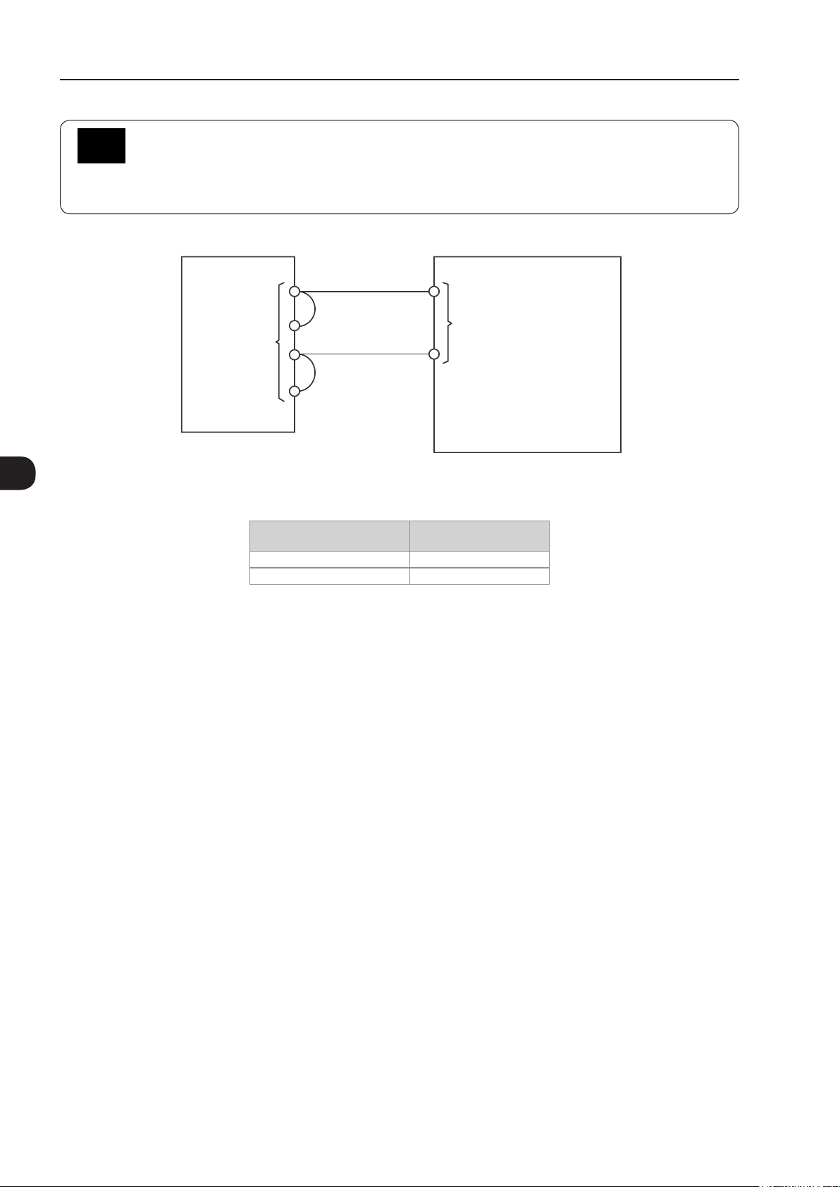
Installation and Connection
NOTE!
Safety Stop function: the inverters with Safety Stop function option (CFW11...O...Y...) are supplied
with control connections to disable Safety Stop function as per Figure 3.39 on page 3-50. For using
the Safety Stop function see Section 3.3 SAFETY STOP FUNCTION on page 3-54.
3
SRBXX (Safety Stop board)
1 (STO1) (24 Vdc) 13
XC25
Figure 3.39 - Internal control connections to disable Safety Stop function
Table 3.13 - Minimum separation distances between wiring
3 (STO2)
2 (GND1)
4 (GND2)
Cable Length
≤ 30 m (100 ft) ≥ 10 cm (3.94 in)
> 30 m (100 ft) ≥ 25 cm (9.84 in)
(DGND*) 11
Minimum Separation
CC11 (control board)
XC1
Distance
4. The correct connection of the cable shield is shown in Figure 3.40 on page 3-50 and Figure 3.41 on page
3-51.
Inverter
side
Insulate with tape
Do not ground
Figure 3.40 - Shield connection
3-50 | CFW-11
Page 81

Installation and Connection
LOC
REM
LOC
REM
3
Figure 3.41 - Example of control wiring shield connection
5. Relays, contactors, solenoids or coils of electromechanical brakes installed close to the inverter may
occasionally generate interferences in the control circuitry. To eliminate this effect, RC suppressors (with AC
power supply) or freewheel diodes (with DC power supply) must be connected in parallel to the coils of these
devices.
3.2.6 Typical Control Connections
Control connection 1 - Run/Stop function controlled from the keypad (Local Mode).
With this control connection, it is possible to run the inverter in local mode with the factory default settings.
This operation mode is recommended for first-time users, since no additional control connections are required.
For the start-up in this operation mode, please follow instructions listed in Chapter 5 FIRST TIME POWER-UP
AND START-UP on page 5-1.
Control connection 2 - 2-Wire Run/Stop function (Remote Mode).
This wiring example is valid only for the default factory settings and if the inverter is set to remote mode.
With the factory default settings, the selection of the operation mode (local/remote) is performed through the HMI
key
(local mode is default). Set P0220 = 3 to change the default setting of HMI key
to remote mode.
CFW-11 | 3-51
Page 82

Installation and Connection
3
≥5 kΩ
Run/Stop
Forward/Reverse (FWD/REV)
Jog
AH
H
XC1 Terminal Strip
1 + REF
2 AI1+
3 AI14 - REF
5 AI2+
6 AI27 AO1
8 AGND (24 V)
9 AO2
10 AGND (24 V)
11 DGND
12 COM
13 24 Vdc
14 COM
15 DI1
16 DI2
17 DI3
18 DI4
19 DI5
20 DI6
21 NC1
22 C1
23 NO1
24 NC2
25 C2
26 NO2
27 NC3
28 C3
29 NO3
*
DO1
(RL1)
DO2
(RL2)
DO3
(RL3)
Figure 3.42 - XC1 wiring for control connection # 2
Control connection 3 - 3-Wire Start/Stop function.
Enabling the Run/Stop function with 3-wire control.
Parameters to set:
Set DI3 to START.
P0265 = 6.
Set DI4 to STOP.
P0266 = 7.
Set P0224 = 1 (DIx) for 3-wire control in Local mode.
Set P0227 = 1 (DIx) for 3-wire control in Remote mode.
Set the Forward/Reverse selection by using digital input # 2 (DI2).
Set P0223 = 4 for Local Mode or P0226 = 4 for Remote Mode.
S1 and S2 are Start (NO contact) and Stop (NC contact) pushbuttons respectively.
The speed reference can be provided through the analog input (as in control connection # 2), through the
keypad (as in control connection # 1) or through other available source.
3-52 | CFW-11
Page 83

Forward/Reverse S3
(FWD/REV)
Start S1
Stop S2
XC1 Terminal Strip
1 + REF
2 AI1+
3 AI14 - REF
5 AI2+
6 AI27 AO1
8 AGND (24 V)
9 AO2
10 AGND (24 V)
11 DGND
12 COM
13 24 Vdc
14 COM
15 DI1
16 DI2
17 DI3
18 DI4
19 DI5
20 DI6
21 NC1
22 C1
23 NO1
24 NC2
25 C2
26 NO2
27 NC3
28 C3
29 NO3
*
DO1
(RL1)
DO2
(RL2)
DO3
(RL3)
Installation and Connection
3
Figure 3.43 - XC1 wiring for control connection # 3
Control connection 4 - Forward/Reverse.
Enabling the Forward/Reverse function.
Parameters to set:
Set DI3 to Forward run.
P0265 = 4.
Set DI4 to Reverse run.
P0266 = 5.
When the Forward/Reverse function is set, it will be active either in Local or Remote mode. At the same time,
the HMI keys and will remain always inactive (even if P0224 = 0 or P0227 = 0).
The direction of rotation is determined by the Forward run and Reverse run inputs.
Clockwise direction for Forward run and counterclockwise for Reverse run.
The speed reference can be provided by any source (as in the control connection # 3).
CFW-11 | 3-53
Page 84

3
Installation and Connection
Stop/Forward S1
Stop/Reverse S2
XC1 Terminal Strip
1 + REF
2 AI1+
3 AI14 - REF
5 AI2+
6 AI27 AO1
8 AGND (24 V)
9 AO2
10 AGND (24 V)
11 DGND
12 COM
13 24 Vdc
14 COM
15 DI1
16 DI2
17 DI3
18 DI4
19 DI5
20 DI6
21 NC1
22 C1
23 NO1
24 NC2
25 C2
26 NO2
27 NC3
28 C3
29 NO3
*
DO1
(RL1)
DO2
(RL2)
DO3
(RL3)
Figure 3.44 - XC1 wiring for control connection # 4
3.3 SAFETY STOP FUNCTION
The inverters CFW11...O...Y... have the board SRBXX that implements Safety Stop function. Through this board it
is possible to control two safety relays (K1 and K2) that actuate directly on the power circuit, more specifically on
the IGBTs gate drivers power supply. The basic functional block diagram is shown in Figure 3.45 on page 3-55.
The safety relays guarantee that the IGBTs remain switched off when Safety Stop function is activated, even in
case of an internal single failure. The position of SRBXX board and XC25 terminals (Safety Stop control terminals)
on the inverter is shown in Figure 3.38 on page 3-49.
The Safety Stop function prevents the motor starting accidentally.
3-54 | CFW-11
Page 85

Installation and Connection
XC25:1 XC1
X1:
DC+
X1:
R/L1
S/L2
T/L3
X1:
DC-
Rectifier
2
+5 V
+5 V
V1
S2
S1
S1
K1
DC Link
capacitors
SR1
K2
Control circuit (Microcontroller+EPLD)
PWM1
Gate
driver
circuit
Gate
driver
circuit
PWM3
Gate
driver
circuit
Gate
driver
circuit
Gate
driver
circuit
Gate
driver
circuit
PWM5
PWM6
PWM4
SR2
PWM2
Digital (Relay)
outputs
X1
U/T1
V/T2
W/T3
Motor
3
V1
S2
XC25:3
Note:
V1 = inverter internal voltage.
4
Figure 3.45 - Basic block diagram of Safety Stop function available in CFW-11 inverter series
DANGER!
The activation of the Safety Stop function does not guarantee electrical safety of the motor terminals
(they are not isolated from the power supply in this condition).
DANGER!
L'activation de la fonction d'arrêt de sécurité ne garantit pas la sécurité électrique des bornes du
moteur (elles ne sont pas isolées de l'alimentation électrique dans cet état).
ATTENTION!
In case of a multiple fault in the power stage of the inverter, the motor shaft can rotate up to 360/
(number of poles) degrees even with the activation of Safety Stop function. That must be considered
in the application.
NOTE!
Inverter Safety Stop function is only one component of the safety control system of a machine and/or
process. When inverter and its Safety Stop function is correctly used and with other safety components,
it’s possible to fulfill the requirements of standard EN 954-1 / ISO 13849-1, Category 3 (machine
safety) and IEC/EN 61508, SIL2 (safety control/signaling applied to processes and systems).
CFW-11 | 3-55
Page 86

Installation and Connection
The parameter P0029 shows if the inverter has identified correctly SRBXX board. See Bit 9 in Table 3.14 on
page 3-56 for details.
Table 3.14 - Content of P0029 parameter
Bits
15 14 13 12 11 10 9 8 7 6 5 4 3 2 1 0
1 1 0 0 = with
braking
IGBT
1 =
without
braking
IGBT
Hexadecimal digit #4 Hexadecimal digit #3 Hexadecimal digit #2 Hexadecimal digit #1
0 0 = control circuit
is supplied from
an external +24
Vdc power supply
1 = control circuit
is fed by the
inverter SMPS
0 = inverter
without safety
stop option
1 = inverter
with Safety
Stop option
0 = inverter
without RFI
filter
1= inverter
with RFI filter
Voltage rating of the
inverter:
00 = 200...240 V
01 = 380...480 V
10 = 500...600 V
11 = 500...690 V
or 660/690 V
Inverter output rated current
3.3.1 Installation
NOTE!
If the degree of protection of the used inverter is lower than IP54, it must be installed inside an IP54
(minimum) cabinet.
3
Table 3.15 - XC25 terminals (Safety Stop terminals) signals
XC25 Terminals Function Specications
1 STO1 Terminal 1 of safety relay K1 coil Coil rated voltage: 24 V, range: 20…30 Vdc
2 GND1 Terminal 2 of safety relay K1 coil
3 STO2 Terminal 1 of safety relay K2 coil Coil rated voltage: 24 V, range: 20…30 Vdc
4 GND2 Terminal 2 of safety relay K2 coil
Coil resistance: 960 Ω ± 10 % @ 20 °C (68 ºF)
Coil resistance: 960 Ω ± 10 % @ 20 °C (68 ºF)
NOTE!
Terminals XC25: 2 and XC25: 4 are not internally connected to the reference of the inverter power
supply +24 V. These terminals are often connected to the control terminal XC1:11.
NOTE!
Follow recommendations of Item 3.2.5 Control Connections on page 3-45.
For XC25 control cabling considers the following:
Use wire gauge from 0.5 mm2 (20 AWG) to 1.5 mm2 (14 AWG) and maximum tightening torque of maximum
0.50 N.m (4.50 lbf.in).
Use shielded cables connected to ground only on inverter side. Use the provided metallic pieces as shown
on Figure 3.41 on page 3-51.
Run the cables separated from the remaining circuits (power, 110 V / 220 Vac control, etc.).
3-56 | CFW-11
Page 87

3.3.2 Operation
3.3.2.1 Truth Table
Installation and Connection
Table 3.16 - Safety Stop function operation
STO1 Logic Level
(Voltage Between
XC25:1-2
Terminals)
0 (0 V) 0 (0 V) Activated
0 (0 V) 1 (24 V)
1 (24 V) 0 (0 V)
1 (24 V) 1 (24 V) Disabled Inverter accepts commands normally
STO2 Logic Level
(Voltage Between
XC25:3-4
Terminals)
Safety Stop
Function
(enabled)
Fault
Inverter Behavior
Inverter remains in STO state and does not accept commands. In order to escape this
condition, it’s required to have STO1 = 1 and STO2 = 1 simultaneously
Inverter is tripped by F160 fault (Safety Stop function related fault). To escape this
condition, it’s required to reset the inverter
NOTE!
Maximum delay between STO1 and STO2 signals: 100 ms (otherwise inverter will be tripped by
F160 fault).
Safety Stop function takes priority over all other functions of the inverter.
This function should not be used as a control for starting and/or stopping the inverter.
3.3.2.2 State of Inverter, Fault and Alarm Related to Safety Stop Function
Table 3.17 - State of inverter, fault and alarm related to Safety Stop function
3
State/Fault/Alarm Description Cause
STO state Safety Stop activated Voltage between terminals 1 and 2 (relay K1 coil) and between terminals 3 and 4 (relay K2 coil)
F160 fault Safety Stop function
fault
of XC25 lower than 17 V
It’s applied voltage to relay K1 coil (STO1) but it’s not applied voltage to relay K2 coil (STO2) or
vice-versa or there is a delay of more than 100 ms between one signal and the other. To solve it,
correct the external circuit that generates STO1 and STO2 signals
3.3.2.3 STO Status Indication
State of the inverter is shown on the left upper side of the display and in parameter P0006.
Possible states of the inverter: ready, run (inverter enabled), undervoltage, fault, self-tuning, configuration, DC
braking and STO (Safety Stop function activated).
It’s possible to set one or more digital and relay outputs of the inverter to indicate that Safety Stop function is
activated (state of the inverter = STO), if the inverter is or not on a fault state and more specifically if the inverter
was tripped by F160 fault (Safety Stop function fault). For that use the parameters P0275 (DO1), P0276 (DO2),
P0277 (DO3), P0278 (DO4) and P0279 (DO5) according to Table 3.18 on page 3-58.
CFW-11 | 3-57
Page 88

Installation and Connection
Table 3.18 - P0275...P0279 options for indication of state of inverter or faults on DOx digital outputs
3
DOx Digital Output Function
State of the inverter = STO
(Safety Stop function activated)
F160 fault
(inverter tripped by Safety Stop function fault actuation)
Fault
(inverter tripped by actuation of any fault)
Without fault
(state of the inverter is not fault)
Value to Be Set on
P0275...P0279
33 Safety Stop function disabled:
relay/transistor OFF
Safety Stop function activated:
relay/transistor ON
34 Without F160 fault: relay/transistor OFF
With fault F160: relay/transistor ON
13 Without fault: relay/transistor OFF
With fault: relay/transistor ON
26 With fault: relay/transistor OFF
Without fault: relay/transistor ON
Comment
Refer to inverter programming manual for a complete list of options for parameters P0275...P0279.
3.3.2.4 Periodic Test
Safety Stop function, alternatively safety stop inputs (STO1 and STO2), must be activated at least once a year
for preventive maintenance purposes. Inverter power supply must be switched off and then on again before
carrying out this preventive maintenance. If during testing the power supply to the motor is not switched off,
safety integrity is no longer assured for the Safety Stop function. The drive must therefore be replaced to ensure
the operational safety of the machine or of the system process.
3-58 | CFW-11
Page 89

Installation and Connection
3.3.3 Examples of Wiring Diagrams of Inverter Control Signal
It is recommended to use inverter DI1 and DI2 digital inputs set as 3-wire start/stop commands and the wiring
diagrams of inverter control signal according to Figure 3.46 on page 3-59.
XC1:1 - DGND*
XC1:12 - COM
XC25:2 - GND (R1-)
XC25:4 - GND (R2-)
XC1:13 - +24 V
Start
XC1:15 - DI1
Stop
XC1:16 - DI2
XC25:1 - STO1 (R1+)
XC25:3 - STO2 (R2+)
3
Safety relay
CFW-11
(a) STO or SS0 safety function (without an external safety relay)
XC1:11 - DGND*
XC1:12 - COM
XC25:2 - GND (R1-)
XC25:4 - GND (R2-)
XC1:13 - +24 V
13 23 47 57
External
safety relay
XC1:15 - DI1
XC1:16 - DI2
XC25:1 - STO1 (R1+)
XC25:3 - STO2 (R2+)
CFW-11
Note:
(*) For specifications of external safety relay, which is required to realize SS1 (stop category 1), refer to Item 3.3.4 Technical Specifications
on page 3-60.
Figure 3.46 - (a) and (b) - Inverter control wiring examples (XC1 and XC25 terminals) to realize STO (or SS0, i.e., stop category 0)
and SS1 (stop category 1) safety functions according to IEC/EN 61800-5-2 and IEC/EN 60204-1 standards - DI1 and DI2 inputs set
Start
Stop
(b) SS1 safety function with an external safety relay
as 3-wire start/stop commands
14 24 48 58
(*)
A1 A2
CFW-11 | 3-59
Page 90

Installation and Connection
Circuit operation of SS1 function from Figure 3.46 on page 3-59:
In this case, when the activation command is given to the external safety relay, safety relay opens inverter DI2
signal (via terminals 23 to 24) and motor is decelerated first by the inverter (via deceleration ramp). When
the time delay set at the external safety relay expires (this delay must be higher than required time to stop the
motor, taking into account deceleration time set on the inverter and inertia of the motor load), the safety relay
delayed contacts (terminals 47 to 48 and 57 to 58) opens inverter STO1 and STO2 signals and the inverter
Safety Stop function is activated. The motor stops according to category 1 (SS1) of standard IEC/EN 60204-1.
In order to drive the motor again, it is required to apply STO1 and STO2 signals again (to close terminals 13
to 23 and 23 to 24) and apply a pulse on inverter DI1 input (START).
3.3.4 Technical Specifications
3.3.4.1 Electrical Control Characteristics
3
Safety Stop function inputs XC25:1-2, XC25:3-4 2 independent inputs for Safety Stop function
External safety relay
specifications (only when SS1
function is required according
to IEC/EN 61800-5-2 and
IEC/EN 60204-1 standards)
refer to Figure 3.46 on page
3-59
General requirements IEC 61508 and/or EN 954-1 and/or ISO 13849-1
Output requirements Number of current paths: 2 independent paths (one for each STO path)
Example Type/manufacturer: WEG/ Instrutech CPt-D
Power supply: 24 Vdc (max. 30 V)
Impedance: 960 Ω
State 0 if < 2 V, state 1 if > 17 V
Switching voltage capability: 30 Vdc per contact
Switching current capability: 100 mA per contact
Maximum switching delay between contacts: 100 ms
3.3.4.2 Operational Safety Characteristics
Protection Of the machine Safety Stop function which forces stopping and/or prevents the motor from restarting
Of the system process Safety Stop function which forces stopping and/or prevents the motor from restarting
unintentionally, conforming to EN 954-1 / ISO 13849-1 category 3, IEC/EN 61800-5-2
and IEC/EN 60204-1
unintentionally, conforming to IEC/EN 61508 level SIL2 and IEC/EN 61800-5-2
3-60 | CFW-11
Page 91

3.3.4.3 Certification
Installation and Connection
3
CFW-11 | 3-61
Page 92

Installation and Connection
3.4 INSTALLATION ACCORDING TO THE EUROPEAN DIRECTIVE OF ELECTROMAGNETIC COMPATIBILITY
The inverters CFW11...T5... and CFW11...T6... (except the ones with NF option - CFW11...O...NF...) have
internal RFI filter for the reduction of the electromagnetic interference.
These inverters, when properly installed, meet the requirements of the electromagnetic compatibility directive
‘’EMC Directive 2004/108/EC’’.
The CFW-11 inverter series has been designed only for industrial applications. Therefore, the emission limits
of harmonic currents defined by the standards EN 61000-3-2 and EN 61000-3-2/A14 are not applicable.
ATTENTION!
For using models with internal RFI filters in IT networks follow the instructions on Item 3.2.3.1.2 IT
Networks on page 3-35.
3
3.4.1 Conformal Installation
For the conformal installation use:
1. Shielded output cables (motor cables) with the shield connected at both ends, motor and inverter, by means
of a low impedance to high frequencies connection.
Use the clamps supplied with the product, making sure there is a good contact between the shield and that
clamp.
Keep the separation distance to the other cables according to the Table 3.11 on page 3-43 indication.
Refer to the Item 3.2.3 Power Connections on page 3-31, for more information.
Maximum motor cable length and conduced and radiated emission levels according to the Table 3.19 on
page 3-64.
If a lower conducted emission level category is wished, then an external RFI filter must be used at the inverter
input. For more information (RFI filter commercial reference, motor cable length and emission levels) refer
to the Table 3.20 on page 3-65.
2. Shielded control cables, keeping the separation distance to other cables according to the Item 3.2.5 Control
Connections on page 3-45.
3. Inverter grounding according to the Item 3.2.4 Grounding Connections on page 3-44.
3-62 | CFW-11
Page 93

Installation and Connection
3.4.2 Standard Definitions
IEC/EN 61800-3: "Adjustable Speed Electrical Power Drives Systems"
- Environment:
First Environment: includes domestic premises, it also includes establishments directly connected without
intermediate transformer to a low-voltage power supply network which supplies buildings used for domestic
purposes.
Example: houses, apartments, commercial installations, or offices located in residential buildings.
Second Environment: includes all establishments other than those directly connected to a low-voltage power
supply network which supplies buildings used for domestic purposes.
Example: industrial area, technical area of any building supplied by a dedicated transformer.
- Categories:
Category C1: inverters with a voltage rating less than 1000 V and intended for use in the First Environment.
Category C2: inverters with a voltage rating less than 1000 V, intended for use in the First Environment, not
provided with a plug connector or a movable installations, and installed and commissioned by a professional.
Note: a professional is a person or organization familiar with the installation and/or commissioning of inverters,
including the EMC aspects.
Category C3: inverters with a voltage rating less than 1000 V and intended for use in the Second Environment
only (not designed for use in the First Environment).
Category C4: inverters with a voltage rating equal to or greater than 1000 V, or with a current rating equal to
or greater than 400 Amps, or intended for use in complex systems in the Second Environment.
EN 55011: Threshold values and measuring methods for radio interference from industrial, scientic
and medical (ISM) high-frequency equipment standard.
Class B: equipment intended for use in the low-voltage power supply network (residential, commercial, and
light-industrial environments).
3
Class A1: equipment intended for use in the low-voltage power supply network. Restricted distribution.
Note: must be installed and commissioned by a professional when applied in the low-voltage power supply
network.
Class A2: equipment intended for use in industrial environments.
CFW-11 | 3-63
Page 94

3
Installation and Connection
3.4.3 Emission and Immunity Levels
Table 3.19 - Emission and immunity levels
EMC Phenomenon Basic Standard Level
Emission:
Mains terminal disturbance voltage
Frequency range: 150 kHz to 30 MHz
Electromagnetic radiation disturbance
Frequency range: 30 MHz to 1000 MHz
Immunity:
Electrostatic discharge (ESD) IEC 61000-4-2 (2008) 4 kV for contact discharge and 8 kV for air discharge
Fast transient-Burst IEC 61000-4-4 (2012) 2 kV / 5 kHz (coupling capacitor) power input cables
Conducted radio-frequency common mode IEC 61000-4-6 (2013) 0.15 to 80 MHz; 10 V; 80 % AM (1 kHz)
Surge immunity IEC 61000-4-5 (2014)
Radio-frequency electromagnetic field IEC 61000-4-3 (2010) 80 MHz to 1000 GHz
IEC/EN61800-3 (2004) +
A1 (2011)
It depends on the inverter model and on the motor cable
lenght. Refer to Table 3.20 on page 3-65
1 kV / 5 kHz control cables, and remote keypad cables
2 kV / 5 kHz (coupling capacitor) motor output cables
Motor cables, control cables, and remote keypad cables
1.2/50 µs, 8/20 µs
1 kV line-to-line coupling
2 kV line-to-ground coupling
10 V/m
1,4 GHz to 2 GHz
3 V/m
2 GHz to 2,7 GHz
1 V/m
80 % AM (1 kHz)
3-64 | CFW-11
Page 95

Installation and Connection
Table 3.20 - Conducted and radiated emission levels
Without External RFI Filter With External RFI Filter
Conducted
Emission
Inverter
Model
CFW110002T5 TBD TBD TBD TBD TBD TBD
CFW110004T5 TBD TBD TBD TBD TBD TBD
CFW110007T5 TBD TBD TBD TBD TBD TBD
CFW110010T5 TBD TBD TBD TBD TBD TBD
CFW110012T5 TBD TBD TBD TBD TBD TBD
CFW110017T5 TBD TBD TBD TBD TBD TBD
CFW110022T5 TBD TBD TBD TBD TBD TBD
CFW110027T5 TBD TBD TBD TBD TBD TBD
CFW110032T5 TBD TBD TBD TBD TBD TBD
CFW110044T5 TBD TBD TBD TBD TBD TBD
CFW110002T6 25 m C3
CFW110004T6 25 m C3 75 m - C2
CFW110007T6 25 m C3 75 m - C2
CFW110010T6 25 m C3 75 m - C2
CFW110012T6 25 m C3
CFW110017T6 25 m C3 75 m - C2
CFW110022T6 25 m C3
CFW110027T6 25 m C3 75 m - C2
CFW110032T6 25 m C3
CFW110044T6 25 m C3 75 m - C2
CFW110053T6 100 m C3
CFW110063T6 100 m C3 50 m C2 C1
CFW110080T6 100 m C3 50 m C2 C1
CFW110107T6 100 m C3 50 m C2 C1
CFW110125T6 100 m C3 50 m C2 C1
CFW110150T6 100 m C3 50 m C2 C1
CFW110170T6 50 m C3
CFW110216T6 50 m C3 25 m - C2
CFW110289T6 50 m C3 B84143B0320S21 25 m - C2
CFW110315T6 50 m C3
CFW110365T6 50 m C3 25 m - C2
CFW110435T6 50 m C3
CFW110472T6 50 m C3 25 m - C2
CFW110584T6 100 m C4
CFW110625T6 100 m C4
CFW110758T6 100 m C4
CFW110804T6 100 m C4
(1) For more details contact Weg.
- Maximum Motor
Cable Length
Category C3Category without
Radiated Emission
metal panel
(1)
(1)
(1)
(1)
External
RFI Filter
Part Number
B84143A25R21
B84143A36R21
B84143A50R21
B84143A80R21
B84143B180S081
B84143B0250S21
B84143B0400S21
B84143B0600S21
B84143B1000S81
Conducted
Emission -
Maximum Motor
Cable Length
Category C2Category without
75 m - C2
75 m -
75 m - C2
75 m - C2
50 m C2 C1
25 m - C2
25 m - C2
25 m - C2
- - -
- - -
- - -
- - -
Radiated Emission
Metal Panel
Category with
Metal Panel
3
C2
CFW-11 | 3-65
Page 96

Installation and Connection
3
3-66 | CFW-11
Page 97

Keypad and Display
4 KEYPAD AND DISPLAY
This chapter describes:
The operator keys and their functions.
The indications on the display.
How parameters are organized.
4.1 INTEGRAL KEYPAD - HMI-CFW11
The integral keypad can be used to operate and program (view/edit all parameters) of the CFW-11 inverter.
The inverter keypad navigation is similar to the one used in cell phones and the parameters can be accessed
in numerical order or through groups (Menu).
Left soft key: press this key to select the
above highlighted menu feature.
1. Press this key to advance to the next
parameter or to increase a parameter value.
2. Press this key to increase the speed.
3. Press this key to select the previous
group in the parameter groups.
Press this key to define the direction of
rotation for the motor.
Active when:
P0223 = 2 or 3 in LOC and/or
P0226 = 2 or 3 in REM.
Press this key to switch between LOCAL
or REMOTE modes.
Active when:
P0220 = 2 or 3.
Press this key to accelerate the motor to the speed set in P0122 in the time set for
the acceleration ramp.
The motor speed is kept while this key is pressed.
Once this key is released, the motor will stop by following the deceleration ramp.
This function is active when all conditions below are satisfied:
1. Start/Stop = Stop.
2. General Enable = Active.
3. P0225 = 1 in LOC and/or P0228 = 1 in REM.
Right soft key: press this key to select the
above highlighted menu feature.
1. Press this key to move back to the previous
parameter or to decrease a parameter value.
2. Press this key to decrease speed.
3. Press this key to select the next group in
the parameter groups.
Press this key to accelerate the motor in the
time set for the acceleration ramp.
Active when:
P0224 = 0 in LOC or
P0227 = 0 in REM.
Press this key to stop the motor in the time
set for the deceleration ramp
Active when:
P0224 = 0 in LOC or
P0227 = 0 in REM.
.
4
Figure 4.1 - Operator keys
Battery:
NOTE!
The battery is necessary only to keep the internal clock operation when the inverter stays without
power. If the battery is completely discharged or if it is not installed in the keypad, the displayed clock
time will be invalid and an alarm condition "A181 - Invalid clock time", will be indicated whenever
the AC power is applied to the inverter.
CFW-11 | 4-1
Page 98

Keypad and Display
The battery life expectancy is of approximately 10 years. When necessary, replace the battery by another of the
CR2032 type.
1 2 3
Cover
4
Cover for battery access
4 5 6
Remove the battery with the
help of a screwdriver positioned
in the right side
7 8
Press the cover and rotate it
counterclockwise
HMI without the battery
Remove the cover
Install the new battery positioning it rst at
the left side
NOTE!
4-2 | CFW-11
Press the battery for its insertion
Figure 4.2 - HMI battery replacement
Put the cover back and rotate it clockwise
At the end of the battery useful life, please do not discard batteries in your waste container, but use
a battery disposal site.
Page 99

Keypad and Display
Installation:
The keypad can be installed or removed from the inverter with or without AC power applied to the inverter.
The HMI supplied with the product can also be used for remote command of the inverter. In this case, use a
cable with male and female D-Sub9 (DB-9) connectors wired pin to pin (mouse extension type) or a market
standard Null-Modem cable Maximum length of 10 m (33 ft). It is recommended the use of the M3 x 5.8
standoffs supplied with the product. Recommended torque: 0.5 Nm (4.5 lbf in).
When power is applied to the inverter, the display automatically enters the monitoring mode. Figure 4.3 on
page 4-3 presents the monitoring screen displayed for the factory default settings. By properly setting specific
inverter parameters, other variables can be displayed in the monitoring mode or the value of a parameter can
be displayed using bar graphs or with larger characters as presented in Figure 4.3 on page 4-3.
Indication of the
control mode:
Indication of the direction
of rotation of the motor.
- LOC: local mode.
- REM: remote mode.
Indication of the motor
speed in rpm.
Inverter status:
- Run
- Ready
- Config
- Self-tuning
- Last fault: FXXX
- Last alarm: AXXX
- etc.
Left soft key feature.
Run
rpm
A
Hz
Monitoring parameters:
- Motor speed in rpm.
Run
LOC
1800rpm
1800 rpm
1.0 A
60.0 Hz
12:35 Menu
Right soft key feature.
Clock.
Settings via:
P0197, P0198, and P0199.
(a) Monitoring screen with the factory default settings
Monitoring parameters:
- Motor speed in rpm.
1800rpm
LOC
100%
10%
100%
12:35 Menu
- Motor current in Amps.
- Output frequency in Hz (default).
P0205, P0206, and P0207: selection of parameters
that will be displayed in the monitoring mode.
P0208 to P0212: engineering unit for the speed
indication.
- Motor current in Amps.
- Output frequency in Hz (default).
P0205, P0206, and P0207: selection of parameters
that will be displayed in the monitoring mode.
P0208 to P0212: engineering unit for the speed
indication.
4
(b) Example of a monitoring screen with bar ghaphs
Run
1800
(c) Example of a monitoring screen displaying a parameter with a larger font size
1800rpm
LOC
Value of one of the parameters defined in P0205, P0206
or P0207 displayed with a larger font size.
12:35 Menu
rpm
Figure 4.3 - (a) to (c) - Keypad monitoring modes
Set parameters P0205, P0206 or P0207 to 0 if it is not
desirable to display them.
CFW-11 | 4-3
Page 100

4
Keypad and Display
4.2 PARAMETERS ORGANIZATION
When the right soft key ("MENU") is pressed in the monitoring mode, the display shows the first 4 groups of
parameters. An example of how the groups of parameters are organized is presented in Table 4.1 on page
4-4. The number and name of the groups may change depending on the firmware version used. For further
details on the existent groups for the firmware version used, please refer to the software manual.
Table 4.1 - Groups of parameters
Level 0 Level 1 Level 2 Level 3
Monitoring 00 ALL PARAMETERS
01 PARAMETER GROUPS 20 Ramps
21 Speed References
22 Speed Limits
23 V/f Control
24 Adjust. V/f Curve
25 VVW Control
26 V/f Current Limit.
27 V/f DC Volt. Limit.
28 Dynamic Braking
Vector Control 90 Speed Regulator
29
30 HMI
31 Local Command
32 Remote Command
33 3-Wire Command
34 FWD/REV Run Comm.
35 Zero Speed Logic
36 Multispeed
37
38
39 Analog Outputs
40 Digital Inputs
41 Digital Outputs
42
43 Motor Data
44 FlyStart/RideThru
45 Protections
46 PID Regulator
47 DC Braking
48 Skip Speed
49 Communication 110 Local/Rem Config.
50 SoftPLC
51 PLC
52 Trace Function
02 ORIENTED START-UP
03 CHANGED PARAMETERS
04 BASIC APPLICATION
05 SELF-TUNING
06 BACKUP PARAMETERS
I/O CONFIGURATION 38 Analog Inputs
07
08 FAULT HISTORY
09 READ ONLY PARAMS.
39 Analog Outputs
40 Digital Inputs
41 Digital Outputs
Electr. Potentiom.
Analog Inputs
Inverter Data
91 Current Regulator
92 Flux Regulator
93 I/F Control
94 Self-Tuning
95 Torque Curr. Limit.
96 DC Link Regulator
111 Status/Commands
112 CANopen/DeviceNet
113 Serial RS-232/485
114 Anybus
115 Profibus DP
4-4 | CFW-11
 Loading...