

Page 1
Motors | Automation | Energy | Transmission & Distribution | Coatings
Automatic Voltage Regulator
Regulador Automático de Tensión
Regulador Automático de Tensão
AVR-A-OPT-04E
AVR-A-OPT-05PE
Installation, Operation and Maintenance Manual
Manual de Instalación, Operación y Mantenimiento
Manual de Instalação, Operação e Manutenção
Page 2

Page 3

Installation, Operation and Maintenance Manual
Manual de Instalación, Operación y Mantenimiento
Manual de Instalação, Operação e Manutenção
Document # / Nº do documento: MWML00512
Models / Modelos: AVR-A-OPT-04E, AVR-A-OPT-05PE
Language / Idioma: English / Español / Português
Revision / Revisión / Revisão: 04
October / Octubre / Outubro, 2017
Page 4

Page 5

GENERAL INDEX / ÍNDICE GENERAL / ÍNDICE GERAL
Installation, Operation and Maintenance Manual
Page 7 - 20
Manual de Instalación, Operación y Mantenimiento
Páginas 21 - 34
Manual de Instalação, Operação e Manutenção
Páginas 35 - 51
Português Español English
Page 6

Page 7
www.weg.net
Automatic Voltage Regulator – AVR-A-OPT-04E / AVR-A-OPT-05PE l 7
FOREWORD
This manual may in no way be reproduced, filed or transmitted through any type of media, whether
it be electronically, by printing, phonographically or any other audiovisual means without prior
consent from WEG. Infringement is subject to prosecution under the law.
Due to the continuous improvement of WEG products, the present manual may be modified and/or
updated without prior notice which may result in new revisions of the installation and maintenance
manuals for the same product.
WEG reserves itself the right not to update automatically the information included in this manual.
However, customers may at any time request any updated version of the manual, which will be
supplied to them free of charge.
If requested, WEG can supply an extra copy of this manual. The equipment serial number and
model should be informed by the customer, when making the request.
ATTENTION
1. It is absolutely necessary to follow the procedures contained in this manual for the warranty to be valid.
2. The alternator installation, operation and maintenance must be executed by qualified personnel.
NOTES
1. The total or partial reproduction of the information supplied in this manual is authorized, provided that
reference is made to its source;
2. If this manual is lost, an electronic PDF file is available from our website www.weg.net or another
printed copy can be requested.
Page 8

Page 9

www.weg.net
Automatic Voltage Regulator – AVR-A-OPT-04E / AVR-A-OPT-05PE l 9
INDEX
1 SAFETY INFORMATION .............................................................................................. 11
2 STORAGE INFORMATION .......................................................................................... 11
3 INTRODUCTION ........................................................................................................... 11
4 TECHNICAL CHARACTERISTICS .............................................................................. 12
5 REGULATOR NAMEPLATE ........................................................................................ 12
6 BLOCK DIAGRAM ....................................................................................................... 13
7 TRIMPOTS FUNCTION ................................................................................................ 13
8 TRIMPOTS ADJUSTMENT .......................................................................................... 13
9 OPERATION ................................................................................................................. 14
9.1 VOLTAGE REGULATOR .................................................................................................................. 14
9.2 POWER CIRCUIT CONNECTION .................................................................................................... 14
9.3 FIELD FLASHING ............................................................................................................................. 14
9.4 U/F OPERATION .............................................................................................................................. 14
9.5 PARALLEL OPERATION FOR TWO OR MORE ALTERNATORS ................................................... 15
10 CONNECTION DIAGRAMS .......................................................................................... 16
10.1 CONNECTION FOR ALTERNATOR WITHOUT AUXILIARY COIL .................................................. 16
10.2 CONNECTION FOR ALTERNATOR FITTED WITH AUXILIARY COIL ............................................ 17
11 DIMENSIONAL DRAWINGS (MM) ............................................................................... 18
12 IDENTIFICATION OF CONNECTION TERMINALS ..................................................... 18
13 DIAGRAM FOR TEST WITHOUT ALTERNATOR ....................................................... 18
14 PROBLEMS, CAUSES AND CORRECTIVE ACTIONS ............................................... 20
15 PREVENTIVE MAINTENANCE .................................................................................... 20
16 WARRANTY ................................................................................................................. 20
Page 10

Page 11

www.weg.net
Automatic Voltage Regulator – AVR-A-OPT-04E / AVR-A-OPT-05PE l 11
1 SAFETY INFORMATION
To guarantee the safety of the operators, the correct installation and proper operation of the equipment, the following
precautions must be taken:
Installation and maintenance services should be performed only by qualified personnel, using appropriate equipment;
The product instruction manual and specific product documentation must always be consulted before proceeding with
its installation, handling and parameter setting;
Adequate precautions should be taken to avoid drops, knocks and/or risks to the operators and the equipment.
Always disconnect the main power supply and wait for the alternator to come to a complete stop, before touching any
electrical component associated with the equipment including the control connectors. Do not touch the input and output
connectors since high voltages may be present even after the power has been switched off and keep them isolated from
the rest of the main command circuit of the alternator.
2 STORAGE INFORMATION
If the alternator needs to be stored for a short period of time before its installation and/or start-up, the following measures
should be taken:
The regulator must remain in its original package or in a similar package which provides the same safety conditions
against mechanical damages, excessive temperature and humidity so as to avoid rusting of contacts and metallic parts,
damages to integrated circuits or any other damage arising from improper storage;
Properly packaged, the regulator must be kept in a dry and well-ventilated area away from direct sunlight, rain, wind
and other adverse weather conditions in order to ensure the preservation of its operational functions.
Failure to comply with the above mentioned recommendations could exempt the supplier of the equipment from any
responsibilities and liabilities from any resulting damages as well as voiding the warranty on the equipment or damaged
part.
3 INTRODUCTION
The AVR-A-OPT automatic analog voltage regulators are compact while featuring high reliability and low cost. They were
designed with state-of-the-art technology for voltage regulation of brushless synchronous alternators.
Their control and regulation circuits use semiconductors and integrated circuits duly tested following the most demanding
quality requirements. Mechanical components for field flashing are not required, and its system is completely solid state
and encapsulated in epoxy resin suitable for maritime environments and able to withstand vibrations of up to 50 mm/s. It
is fitted with internal voltage adjustment by trimpot and external by potentiometer allowing a alternantor voltage
adjustment.
The PID control system is adjusted with two trimpots that adjust the proportional gain and the integral gain allowing a
wide adjustment range while allowing operation of the regulator with several types of alternators, and with a high number
of dynamic characteristics. The under frequency protection set point is adjustable by trimpot, and the nominal operating
frequency can be set to 50Hz or 60Hz.
Page 12
www.weg.net
12 l Automatic Voltage Regulator – AVR-A-OPT-04E / AVR-A-OPT-05PE
4 TECHNICAL CHARACTERISTICS
Table 4.1: Technical characteristics
Model
Characteristics
AVR-A-OPT-04E AVR-A-OPT-05PE
Nominal operating current 5A 7A
Peak Current 7A 10A
Analog input ±9Vdc Yes
Droop adjustment for parallel operation Yes
CSA certification Yes
Sensing Input 160-300 Vac or 320-600 Vac (Vsen)
Power supply
170-300 Vac (1∅ or 2∅)
Rectifier gain ratio 0,45
Output voltage¹ 76,5-126 Vdc
Field resistance @ 20ºC 6 up to 50Ω
Static regulation 0,5%
Adjustable dynamic response 8 up to 500ms
Operating frequency 50 or 60Hz
Under Frequency protection (U/F) Adjustable
Internal voltage adjustment Adjustable via trimpot, for the complete range of Voltage
External voltage adjustment² - 30% (Vsen)
Operating Temperature -20° to +60ºC
EMI suppression EMI Filter
Approximate weight 480 g
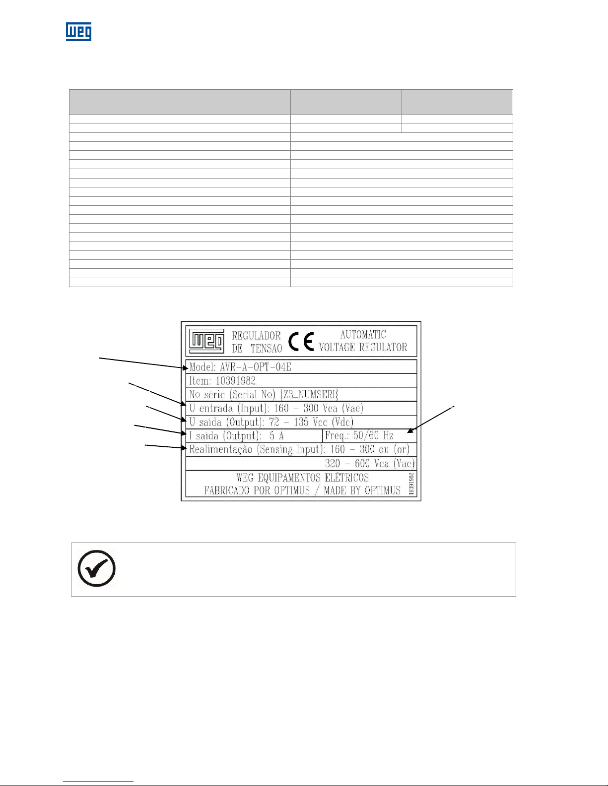
5 REGULATOR NAMEPLATE
The example above shows the main characteristics to be followed before installation.
NOTE
The identification nameplate is attached to the bottom of the regulator frame.
¹ For an input voltage of 170Vac, the maximum output voltage obtained is 76.5Vdc.
For 280Vac of input voltage, the output voltage obtained is 126Vdc, that is, the maximum dc output voltage is equal to
0.45 x the ac voltage input.
² Recommended the use of multi-turn potentiometer.
Figure 5.1: Regulator Nameplate
Operating Frequency
Model
Power Supply
Excitation Voltage
Rated Current
Sensing Voltage
Page 13
www.weg.net
Automatic Voltage Regulator – AVR-A-OPT-04E / AVR-A-OPT-05PE l 13
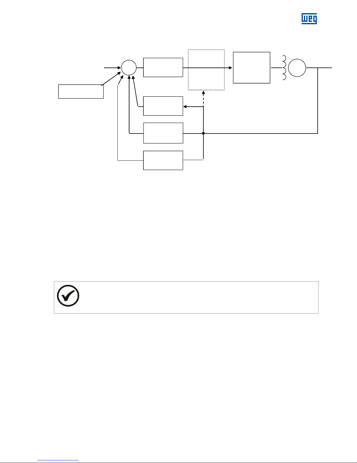
6 BLOCK DIAGRAM
Figure 6.1: Block diagram
7 TRIMPOTS FUNCTION
P1: Voltage adjustment
P2: Droop adjustment.
P3: Stability - 2 adjustment.
P4: Stability - 1 adjustment.
P5: Under frequency adjustment.
8 TRIMPOTS ADJUSTMENT
P1: Rotating CW, voltage increases.
P2: Rotating CW, reactive compensation range increases.
P3: Rotating CW, dynamic response will be slower.
P4: Rotating CW, dynamic response will be slower.
P5: Rotating CW, U/F range increases and rotating CCW, it decreases.
NOTE
* A potentiometer may be connected for fine voltage adjustment (5 kΩ / 3 W) at terminals 6 and 7.
* The P3, P4 and P5 trimpots were preseted and sealed, but if adjustments are required, They can be
performed according to the procedures described in this manual.
Power stage
G
U/F
DROOP
+
+
- +
Analog input
± 9 Vdc
Reference value
Excitation field
Automatic
field flashing
PID
Sensing
Page 14
www.weg.net
14 l Automatic Voltage Regulator – AVR-A-OPT-04E / AVR-A-OPT-05PE
9 OPERATION
9.1 VOLTAGE REGULATOR
It compares the actual output voltage from the alternator with the theoretical adjusted value through the trimpot of voltage
adjustment P1, plus the external voltage adjustment (if any). The error is processed by the sensing loop whose value
determines the thyristor firing angle which may vary from 0 to 180°, thus controlling the output voltage of the alternator.
9.2 POWER CIRCUIT CONNECTION
The alternator voltage or the auxiliary winding voltage is connected to the terminals 3 and E3/4. This rectified voltage is
applied, in a controlled fashion, to the alternator exciter field.
9.3 FIELD FLASHING
Generation begins through the residual voltage of the alternator. Once the voltage has reached about 10% of the nominal
voltage, the regulator controls the alternator voltage causing it to rise through the initial ramp in approximately 3 seconds.
When the alternator reaches its nominal value, the PID control loop will maintain the alternator output voltage constant
within the adjusted value.
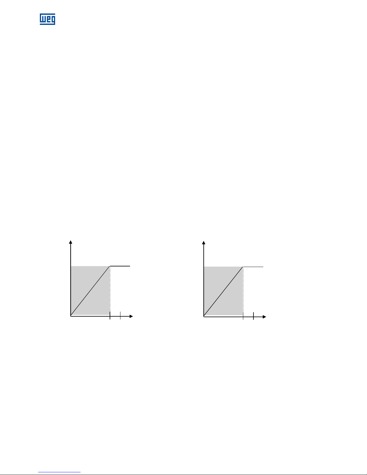
9.4 U/F OPERATION
This operation is determined by trimpot P5, jumper J1 and associated components. The J1 jumper determines the
operating frequency (50 or 60 Hz), following the logic below:
J1 closed = 60 Hz
J1 open = 50 Hz
Trimpot P5 determines the set point of the U/F mode, that can be from the nominal frequency (Fn) down to 1/3 of Fn, the
value of which comes out of the factory adjusted to 10% below Fn. For operation at 60Hz it is adjusted to 54Hz and for
operation at 50 Hz it is adjusted to 45Hz (see Figure 9.1), the value of which can be changed based on each application
requirements.
Figure 9.1: U/F operation
Output voltage (Vac)
Frequency (Hz)
Output voltage (Vac)
Frequency (Hz)
45
U
U/f
50
54
U
U/f
60
Page 15
www.weg.net
Automatic Voltage Regulator – AVR-A-OPT-04E / AVR-A-OPT-05PE l 15
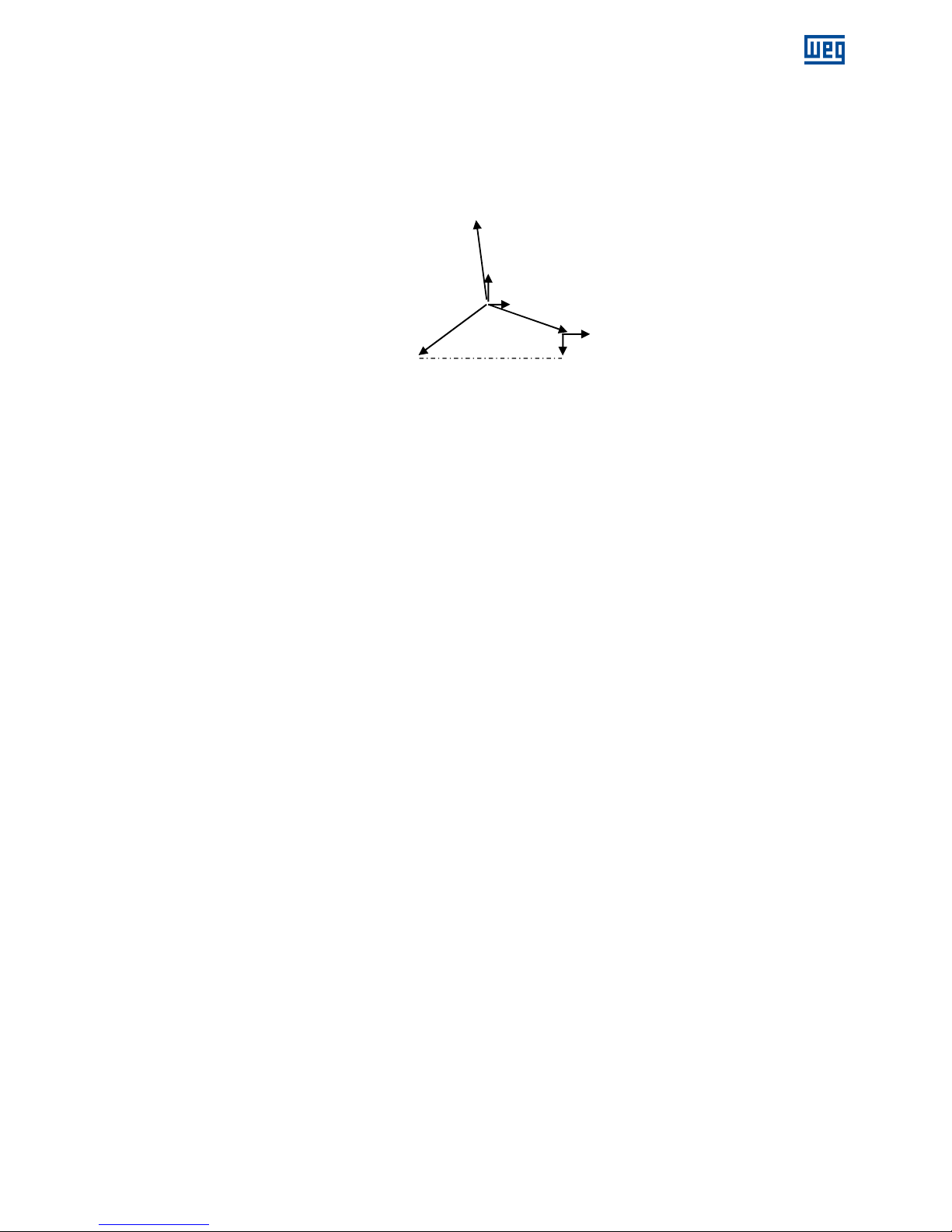
9.5 PARALLEL OPERATION FOR TWO OR MORE ALTERNATORS
The reactive compensation method applied is called a phasor diagram (see Figure 9.2). Through this diagram, the
alternator output voltage signal is measured and compared with the alternator current voltage. The result of this interaction
introduces a sensing error of the actual voltage signal, causing an increase or a decrease in the alternator voltage, thus
maintaining the reactive between the alternators within acceptable values. The adjustment of this compensation is made
through trimpot P2.
Figure 9.2: Phasorial diagram
According to the phasor diagram, the sensing voltage is influenced by the current coming from phase S, which is added to
the voltage of phases R and T. The influence is small in module and large in phase, which means that there is good
compensation for reactive loads and a small influence with active loads.
The current transformer (CT) for reactive compensation must be in phase S of the alternator, and the voltage sensing
signal must be in phases R and T.
To make sure the compensation is in the proper direction, proceed as follows:
Operate the alternator by itself (isolated from the grid) and apply a resistive load with about 20% of the alternator capacity;
After completely rotating the P2 trimpot clock wise (CW), the alternator voltage should decrease.
Rotating back the trimpot completely CCW, alternator voltage should then increase; If this occurs, the CT polarity is correct.
Otherwise the CT should be inverted.
When several alternators are connected in parallel, this procedure is required to ensure that all the CT’s are properly
polarized.
The current transformer for compensation of reactive must be in phase S of the alternator and the feeding signal in the
phase R.
To ensure the correct polarization of TC, Inductive Resistive loads must be applied and the system checked for good
response as below.
Resistive Loads: It will not present compensation with resistive load, keeping the excitation current and alternator voltage
constant in the value adjusted via trimpot Vad. In case of compensation, it indicates that TC is in the wrong phase.
Inductive Loads: With inductive load application, it shall present negative compensation, decreasing the excitation current
corresponding to the gain adjusted in the trimpot droop (0 to 15% voltage adjusted in the Vad). If the compensation is
positive, it indicates the TC is inverted.
Capacitive Loads: With application of capacitive loads, it will present a positive compensation, increasing the excitation
current corresponding to the gain adjusted in the trimpot droop (0 to 15% voltage adjusted in the Vad). If the compensation
is positive, it indicates the TC is inverted.
Accuracy class of 0,6C12,5;
Window or bar type;
Transformer ratio will be In/5A or In/1A, where In/xA is the ratio of the TC primary. Ex.: 100/5A, 150/5A, 100/1A;
5A secondary current for regulator PAR/5 and 1A for regulator PAR/1;
The current in TC primary must be 20% bigger than the nominal current of the machine;
The TC operation frequency must be equal to the alternator frequency;
The TC isolation voltage class must be bigger than the alternator output voltage;
It must support 1.2 x In.
RT R
T
IS
S
Page 16
www.weg.net
16 l Automatic Voltage Regulator – AVR-A-OPT-04E / AVR-A-OPT-05PE
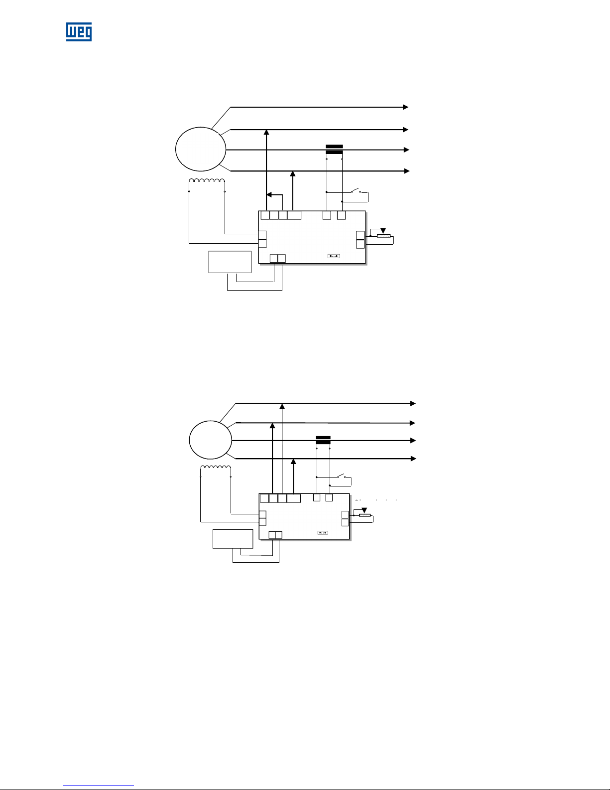
10 CONNECTION DIAGRAMS
10.1 CONNECTION FOR ALTERNATOR WITHOUT AUXILIARY COIL
Figure 10.1: Sensing Voltage of 160 up to 300Vac
Figure 10.2: Sensing Voltage of 320 up to 600Vac
N
R
S
T
Parallelism CT ratio In/5A¹
Exciter
field
F-
F+
Alternator
Potentiometer
for external
voltage
regulation¹ ²
(5kΩ/3W)
AVR
F+
F-
E1 E2
3
7
6
Single/parallel switch¹
Open: parallel;
Closed: single
1 2
P1
P2
S1
S2
E
3/4
J1
A B
Input ± 9V
- +
N
R
S
T
Parallelism CT ratio In/5A¹
Exciter
field
F-F+
Potentiometer for
external voltage
regulation¹ ²
(5kΩ/3W)
AVR
F+
F-
Single/parallel
switch¹
Open: parallel;
P1
P2
S1
S2
J1
A B
Input ± 9V
- +
Alternator
E1 E2
3
E
3/4
Page 17

www.weg.net
Automatic Voltage Regulator – AVR-A-OPT-04E / AVR-A-OPT-05PE l 17
10.2 CONNECTION FOR ALTERNATOR FITTED WITH AUXILIARY COIL
Figure 10.3: Sensing Voltage of 160 up to 300Vac
Figure 10.4: Sensing Voltage of 320 up to 600Vac
1 ITEM NOT SUPPLIED BY WEG.
2 IF NO POTENTIOMETER IS CONNECTED, KEEP TERMINALS 6 AND 7 JUMPED (SHORT-CIRCUITED).
ATTENTION
1. Before connecting the regulator to the alternator, check installation manual and the nominal reference
voltage;
2. If the reference voltage is not equal to the alternator output voltage, do not make the connections
without first contacting the service department.
N
R
S
T
Parallelism CT ratio In/5A¹
Exciter
field
F- F+
Potentiometer for
external voltage
regulation¹ ²
(5kΩ/3W)
AVR
F+
F-
Single/parallel
switch¹
Open: parallel;
Closed: single
J1
A B
Input ± 9V
- +
N
R
S
T
Parallelism CT ratio In/5A¹
Exciter
field
F-F+
Potentiometer for
external voltage
regulation¹ ²
(5kΩ/3W)
AVR
F+
F-
E1
E2 3
Single/parallel
switch¹
Open: parallel;
Closed: single
P1
P2
S1
S2
E
3/4
J1
A B
Input ± 9V
- +
Aux
Coil
Alternator
Alternator
Aux
Coil
E1
E2 3 E
3/4
P1
P2
S1
S2
Page 18

www.weg.net
18 l Automatic Voltage Regulator – AVR-A-OPT-04E / AVR-A-OPT-05PE
11 DIMENSIONAL DRAWINGS (mm)
Figure 11.1: Dimensional
12 IDENTIFICATION OF CONNECTION TERMINALS
E1: Sensing Voltage (160 up to 300Vac);
E2: Voltage (320 up to 600Vca);
3: Power supply;
E3/4: Sensing Voltage;
1: Connection for pole S1 of the CT, ratio In/5A;
2: Connection for pole S2 of the CT, ratio In/5A;
6 e 7: Connection for potentiometer 5KΩ/3W;
F+, F-: Connection for alternator field;
J1: Jumper 50/60Hz (J1 open = 50Hz – closed = 60Hz);
A: Analog input voltage – 9 Vdc;
B: Analog input voltage + 9 Vdc.
13 DIAGRAM FOR TEST WITHOUT ALTERNATOR
Below is the diagram for regulator connection on the bench where the equipment operation may be verified before
connection to the alternator.
Material required:
1 - Small screwdriver;
1 - Incandescent lamp;
1 - Lamp socket;
1 - Bipolar breaker (5A recommended);
1 - Extension cable;
1 - Plug 110V or 220V*.
* For voltage 110V, select refeeding jumper class “A”;
* For voltage 220V, select refeeding jumper class “C”;
NOTE
1. After performance of such steps as per the procedure the equipment must be sent for evaluation by WEG
technical support.
1º. Mount circuit as per diagram below;
2º. With small screwdriver, turn trimpots Vad and U/F counter-clockwise until the end of stroke;
3º. Turn on circuit breaker:
4º. Turn slightly the trimpot Vad clockwise (the lamp must shine after certain position of trimpot)
5º. With lamp on, turn slightly the trimpot Vad counter-clockwise (after certain position of trimpot, the lamp must turn off);
6º. Turn off the circuit breaker.
E1 E2 1 2 7 6 F+ F- 3 E3/4
39,0
Front view
Fixing hole detail
164,0
115,0
100,0
145,0
Overview
P1
P4
P3
P5
P2
50Hz
60Hz
E1 E2 1 2 7 6 F+ F- 3 E3/4
Entrada analógica
- +
A B
Page 19

www.weg.net
Automatic Voltage Regulator – AVR-A-OPT-04E / AVR-A-OPT-05PE l 19
Figure 13.1: Test diagram
Page 20

www.weg.net
20 l Automatic Voltage Regulator – AVR-A-OPT-04E / AVR-A-OPT-05PE
14 PROBLEMS, CAUSES AND CORRECTIVE ACTIONS
Table 14.1
Problems Causes Corrective Actions
There is circulation of reactive power
between alternators when operating in
parallel.
Phases sequence (R-S-T) incorrectly
connected;
CT connections are inverted;
Droop adjustment excessively low.
Connect phase sequence correctly.
Correctly polarize the CT in the phase shown
below:
Increase droop adjustment, rotating trimpot
P2 clockwise (CW).
Generated voltage decreases when load is
applied, and it doesn’t return.
Dropping speed of the driving machine;
Under frequency protection engaged.
Correct speed regulation.
Adjust Under frequency protection by rotating
trimpot P5 clockwise (CW).
Alternator voltage does not increase.
Residual voltage excessively low
Terminals F (+) and F (-) are inverted.
With the regulator switched- on, use external
battery (12Vcc) to force excitation (*).
Invert F (+) and F (-).
Generated voltage oscillates at no load.
Dynamic not well adjusted.
Alternator excitation voltage excessively
low.
Adjust trimpots P3 and P4;
Insert 10Ω/100W resistor in series with field.
Voltage oscillates at a specific load point.
Third harmonic of the auxiliary coil is
high.
Eliminate auxiliary coil and proceed with the
connections according to the diagrams of
page 13.
Voltage surges.
Lack of sensing.
Faulty electronic circuit.
Sensing voltage incompatible with
regulator.
Check if alternator phases are present in the
sensing.
If the regulator is encapsulated, replace it.
(*)For battery diesel generator where the alternator neutral is grounded battery should always be used independently.
15 PREVENTIVE MAINTENANCE
Periodical inspections of
the equipment are required to ensure they are clean, dust and moisture free. It is essential that
all terminal and connections are kept free from corrosion.
16 WARRANTY
See Installation and Maintenance Manual for WEG Alternators.
WEG Group - Energy Business Unit
Jaraguá do Sul - SC - Brazil
Telefono: 55 (47) 3276-4000
energia@weg.net
www.weg.net
P1
P2
S1
S2
Alternator
Load
Page 21

www.weg.net
Regulador Automático de Tensión – AVR-A-OPT-04E / AVR-A-OPT-05PE l 21
PREFACIO
Esta publicación no podrá en ninguna hipótesis ser reproducida, almacenada o transmitida a través de algún
tipo de medio, sea electrónico, impreso, fonográfico o cualquier otro posible medio audiovisual, sin la
autorización previa de WEG Industrias S.A. Los infractores estarán sujetos a las penas previstas en la ley.
Esta publicación podrá ser alterada y / o actualizada y podrán resultar en nuevas revisiones de los manuales
de instalación, operación y mantenimiento, teniendo en vista el continuo perfeccionamiento de los productos
WEG.
La WEG se reserva el derecho de la no-obligatoriedad de actualización automática de las informaciones
contenidas en estas nuevas revisiones. No obstante eso, y en cualquier momento el cliente podrá solicitar
material actualizado que le será provisto sin cargos resultantes.
En caso de pérdida del manual de instrucciones, la WEG podrá proveer ejemplar separado y caso fuera
necesario, informaciones adicionáis sobre el producto. Las solicitaciones podrán ser atendidas, siempre que
sea informado el número de serie y modelo del equipo.
ATENCIÓN
1. Es imprescindible seguir los procedimientos contenidos en este manual para que la garantía tenga
validez;
2. Los procedimientos de instalación, operación y mantenimiento del alternador deberán hacerse por
personal calificado.
NOTAS
1. La reproducción de las informaciones de este manual, total o en partes, se permite desde que la fuente
sea citada;
2.
Si se extraviar este manual, el archivo electrónico en formato PDF está disponible en el sitio
www.weg.net o podrá ser solicitada otra copia impresa.
Page 22

Page 23

www.weg.net
Regulador Automático de Tensión – AVR-A-OPT-04E / AVR-A-OPT-05PE l 23
INDEX
1 INFORMACIONES DE SEGURIDAD ........................................................................... 25
2 INFORMACIONES SOBRE ALMACENAJE ................................................................ 25
3 INTRODUCCIÓN .......................................................................................................... 25
4 CARACTERÍSTICAS TÉCNICAS ................................................................................. 26
5 TARJETA DE IDENTIFICACIÓN .................................................................................. 26
6 DIAGRAMA DE BLOQUES .......................................................................................... 27
7 FUNCIÓN DE LOS TRIMPOTS .................................................................................... 27
8 AJUSTE DE LOS TRIMPOTS ...................................................................................... 27
9 OPERACIÓN ................................................................................................................. 28
9.1 REGULADOR DE TENSIÓN ............................................................................................................. 28
9.2 CONEXIÓN DEL CIRCUITO DE POTENCIA .................................................................................... 28
9.3 ENCENDIDO DEL CAMPO ............................................................................................................... 28
9.4 OPERACIÓN U/F .............................................................................................................................. 28
9.5 OPERACIÓN PARALELA DE DOS O MÁS ALTERNADORES ........................................................ 29
10 DIAGRAMA DE CONEXIÓN ......................................................................................... 30
10.1 CONEXIÓN DEL ALTERNADOR SIN BOBINADO AUXILIAR.......................................................... 30
10.2 CONEXIÓN DEL ALTERNADOR CON BOBINA AUXILIAR. ............................................................ 31
11 DIMENSIONAL (MM) .................................................................................................... 32
12 DESCRIPCIÓN DE LOS TERMINALES DE CONEXIÓN ............................................. 32
13 DIAGRAMA PARA PRUEBA SIN ALTERNADOR ...................................................... 32
14 DEFECTOS, CAUSAS Y SOLUCIONES ...................................................................... 34
15 MANTENIMIENTO PREVENTIVO ................................................................................ 34
16 GARANTIA ................................................................................................................... 34
Page 24

Page 25

www.weg.net
Regulador Automático de Tensión – AVR-A-OPT-04E / AVR-A-OPT-05PE l 25
1 INFORMACIONES DE SEGURIDAD
Para garantizar la seguridad de los operadores, la correcta instalación del equipo y su preservación, las precauciones
abajo deberán ser tomadas:
Los servicios de Instalación y manutención deberán ser hechos solamente por personas calificadas y con manejo de
los equipos correctos;
Deberán siempre ser observados los manuales de instrucción y la tarjeta de identificación del producto antes de
proceder su instalación, manejo y configuración;
Debiese tener especial cuidado para que el equipo no sufra caídas, golpes físicos y / o poniendo en riesgo la
seguridad de las personas.
Siempre desconecte la red general y aguarde hasta la parada total del alternador antes de tocar en cualquier
componente eléctrico asociado al equipo, haciendo también lo mismo en los terminales de comando. No toque en los
conectadores de entradas y salidas porque altas tensiones pueden estar presentes, hasta mismo después de la
desconexión de la red, y mantenga estos siempre aislados de lo restante del circuito de comando principal del
alternador.
2 INFORMACIONES SOBRE ALMACENAJE
En caso de necesidad de almacenaje del regulador por pequeño período de tiempo antes de su instalación y / o
funcionamiento, deberán ser tomadas las precauciones como sigue:
El regulador deberá ser mantenido en su embalaje original o embalaje que atienda las mismas condiciones de
seguridad contra daños mecánicos, temperatura y humedad excesivas, para prevenir la ocurrencia de oxidación de
conexiones, contactos y partes metálicas, daños en circuitos integrados o otros daños provenientes de mala
conservación;
El regulador debidamente acondicionado deberá ser abrigado en local seco, ventilado y que no ocurra la incidencia
directa de los rayos solares, bien como la lluvia, viento y otras intemperies, para garantizar la manutención de sus
características funcionales.
Si no fueren observadas las recomendaciones arriba, podrá eximir el proveedor del equipo de cualquier responsabilidad
pelos daños decurrentes, bien como la perdida de la garantía sobre el equipo o parte dañada.
3 INTRODUCCIÓN
Los reguladores electrónicos de Tensión analógicos de la serie AVR-A-OPT son equipos compactos de alta
confiabilidad y de bajo costo, los cuales fueron desarrollados dentro de la más alta tecnología, para regulación de
Tensión en alternadores sincrónicos sin escobillas (brushless).
Su circuito de control y regulación utiliza semiconductores y circuitos integrados probados dentro de los más rígidos
padrones de calidad. No poseen componentes mecánicos para encender el campo y su sistema es totalmente estático y
encapsulado en resina epoxi resistente à salinidad. Pueden suportar vibraciones hasta 50mm/s. Poseen ajuste de
Tensión interno por trimpot y externo por potenciómetro, posibilitando un rango de ajuste de la tensión del alternador.
Su sistema de controle PID es ajustado a través de trimpots que regulan el ganado proporcional y el ganado integral,
posibilitando un amplio rango de ajuste, o que permite operación con los más diversos tipos de alternadores, y con las
más variadas características dinámicas. Dotados de protección contra sub frecuencia, su ponto de intervención es
ajustable por trimpot, y la frecuencia nominal de operación es configurable para 50 o 60Hz.
Page 26

www.weg.net
34 l Regulador Automático de Tensión – AVR-A-OPT-04E / AVR-A-OPT-05PE
4 CARACTERÍSTICAS TÉCNICAS
Tabla 4.1: Características Técnicas
Modelo
Características
AVR-A-OPT04E AVR-A-OPT-05PE
Corriente nominal de operación 5A 7A
Corriente de Pico (max. 10s) 7A 10A
Entrada analógica ± 9Vcc Si
Droop p/ operación paralela Si
Certificación CSA Si
Regeneración 160-300 Vca o 320-600 Vca (Vsen)
Alimentación de potencia
170-300 Vca (1∅ o 2∅)
Relación de gaño del rectificador 0,45
Tensión de salida ¹ 76,5-126 Vcc
Resistencia de campo @ 20ºC 6 hasta 50Ω
Regulación estática 0,5%
Respuesta dinámica ajustable 8 hasta 500ms
Frecuencia de operación 50 o 60Hz
Protección de subfrecuencia (U/F) Ajustable
Ajuste interno de tensión Ajustable a través del potenciómetro de ajuste, para la
gama completa de tensión.
Ajuste externo de tensión² - 30% (Vsen)
Temperatura de operación -20° a +60ºC
Supresión de EMI Filtro EMI
Peso aproximado 480 g
5 TARJETA DE IDENTIFICACIÓN
El ejemplo arriba muestra las principales características que deben ser observadas antes de la instalación.
NOTA
La tarjeta de identificación se encuentra fijada en la parte inferior del regulador.
¹ Con tensión de entrada en 170Vca, en la salida resulta 76,5 Vcc.
Para 280Vca de tensión de entrada, resulta 126 Vcc de tensión de salida, o sea, la máxima tensión continua de salida
es lo mismo que 0,45 x tensión alternada de entrada.
² Recomendado el uso de multi-vueltas del potenciómetro.
Figura 5.1: Tarjeta de identificación
Modelo
Alimentación de Potencia
Tensión de excitación
Frecuencia de operación
Regeneración de tensión
Page 27

www.weg.net
Regulador Automático de Tensión – AVR-A-OPT-04E / AVR-A-OPT-05PE l 27
6 DIAGRAMA DE BLOQUES
Figura 6.1: Diagrama de bloques
7 FUNCIÓN DE LOS TRIMPOTS
P1: Ajuste de Tensión.
P2: Ajuste del rango de comp. de reactivos (Droop).
P3: Ajuste da Estabilidad – 2.
P4: Ajuste da Estabilidad – 1.
P5: Ajuste de Bajo frecuencia.
8 AJUSTE DE LOS TRIMPOTS
P1: Girando en el sentido horario aumenta la tensión.
P2: Girando en el sentido horario aumenta la faja de compensación de reactivos.
P3: Girando en el sentido horario la respuesta se hace más lenta.
P4: Girando en el sentido horario la respuesta se hace más lenta.
P5: Girando en el sentido horario aumenta la faja de U/F y antihorario diminuye.
NOTA
* Podrá ser conectado potenciómetro para ajuste fin o de tensión (5kΩ/3W) en los bornes 6 y 7.
* Los Trimpots P3, P4 y P5 están pre ajustados y sellados, pero si es necesario hacer ajustes, se
pueden realizar según los procedimientos descritos en este manual
Etapa de
potencia
G
U/F
DROOP
+
+
- +
Entrada analógica
± 9 Vcc(1)
Valor de referencia
Campo de excitación
Encendido
de campo
automático
PID
Regeneración
Page 28

www.weg.net
34 l Regulador Automático de Tensión – AVR-A-OPT-04E / AVR-A-OPT-05PE
9 OPERACIÓN
9.1 REGULADOR DE TENSIÓN
Compara el valor real de tensión del alternador con el valor teórico ajustado a través del trimpot de ajuste de tensión P1,
más el ajuste externo de tensión (caso poseyera). El error se procesa por la malla de regeneración por lo cual el valor
determina el ángulo de gatillo del tiristor que pode variar de 0 hasta 180°, controlando así la tensión de salida del
alternador.
9.2 CONEXIÓN DEL CIRCUITO DE POTENCIA
La tensión del alternador o del bobinado auxiliar, se conecta a los bornes 3 y E3/4. Esta Tensión rectificada es aplicada
controladamente en el campo de la excitatriz del alternador.
9.3 ENCENDIDO DEL CAMPO
La generación empieza a través de la tensión residual del alternador. Después que la tensión atingir aproximadamente
10% de la nominal, el regulador controla la tensión del alternador haciendo con que la tensión ascienda a través de la
rampa inicial en aproximadamente 3 segundos, hasta atingir la tensión nominal. A partir de este momento, el circuito de
controle del PID mantendrá la tensión de salida del alternador constante de acuerdo con el valor ajustado.
9.4 OPERACIÓN U/F
Este modo de operación es determinado por el trimpot P5, jump J1 e componentes asociados. El jump J1 determina la
frecuencia de operación, que sigue la lógica siguiente:
J1 cerrado = 60Hz
J1 abierto = 50Hz
El trimpot P5 determina el punto de actuación del modo U/F, que puede ser de la frecuencia nominal (Fn) hasta 1/3 de
Fn. El valor sale ajustado de la fábrica con 10% abajo de la Fn. Para operación en 60Hz se hace el ajuste para 54Hz y
para operación en 50Hz se hace el ajuste para 45Hz (ver Figura 9.1). Este valor puede ser alterado de acuerdo con la
necesidad de cada aplicación.
Figura 9.1: Operación U/F
Tensión de salida (Vca)
Frecuencia (Hz)
Tensión de salida (Vca)
Frecuencia (Hz)
45
U
U/f
50
54
U
U/f
60
Page 29

www.weg.net
Regulador Automático de Tensión – AVR-A-OPT-04E / AVR-A-OPT-05PE l 29
9.5 OPERACIÓN PARALELA DE DOS O MÁS ALTERNADORES
El sistema de compensación de reactivos utilizado es denominado composición fasorial (vea la Figura 9.2). En este tipo
de sistema, cogiese el sinal de tensión de salida del alternador e se hace la composición con el sinal de corriente del
alternador. Lo que resulta de esta interacción introduce un error en la regeneración del sinal real de tensión,
provocando un aumento o una disminución en la tensión del alternador, haciendo con que el reactivo entre los
alternadores se quede dentro de los valores aceptables. El ajuste de esta compensación es hecho a través del trimpot
P2.
Figura 9.2: Diagrama fasorial
Según el gráfico, la tensión de regeneración sufre una influencia causada por la corriente de la fase S que es agregada
con la tensión de las fases R y T. Esta influencia es pequeña en módulo y grande en fase, o que significa decir que hay
una buena compensación para cargas reactivas e una pequeña influencia para las cargas activas.
El transformador de corriente para compensación de reactivos deberá estar en la fase S del alternador, y el señal de
regeneración en las fases R y T.
Para garantizar que la compensación está en sentido correcto, proceda de la manera siguiente:
Accionar un alternador sencillo (aislado de la red), aplicar una carga resistiva con cerca de 20% de la capacidad del
alternador;
Después de esto ruede el trimpot P2 completamente en el sentido horario, en esta operación debe ocurrir una baja de
tensión en el alternador.
Volviendo el trimpot nuevamente para la posición antihorario la tensión deberá aumentar. Caso esto ocurrir, la polaridad
del TC está correcta, caso contrario, el TC deberá ser invertido.
Cuando se conecta algunos alternadores en paralelo este procedimiento es necesario en cada alternador, para
garantizarse que todos los TC’s están polarizados de la misma manera.
El transformador de corriente para compensación de reactivos deberá estar en la fase S del alternador y la señal de
realimentación en la fase R.
Para certificar la correcta polarización del TC, debe aplicarse cargas Resistivas Inductivas y verificar si el sistema
responde conforme se muestra a continuación.
Cargas resistivas: Con carga resistiva no presentará compensación, manteniendo la corriente de excitación y tensión del
alternador constante en el valor ajustado a través del trimpot Vad. Si existe compensación, indica que el TC está en la
fase errada.
Cargas Inductivas: Con aplicación de cargas inductivas, presentará una compensación negativa, disminuyendo de la
corriente de excitación correspondiendo a la ganancia ajustada en el trimpot droop (del 0 al 15% tensión ajustada en l
Vad). Si la compensación es positiva indica que el TC está invertido.
Cargas Capacitivas: Con aplicación de cargas capacitivas, presentará una compensación positiva, aumentando la
corriente de excitación correspondiendo a la ganancia ajustado en el trimpot droop (del 0 al 15% tensión ajustada en el
Vad). Si la compensación es negativa indica que el TC está invertido.
Clase de exactitud de 0,6C12,5;
Tipo ventana o barra;
La relación de transformación será In/5A o In/1A, donde In/xA es la relación del primario del TC. Ej.: 100/5A, 150/5A,
100/1A;
Corriente de secundario de 5A para regulador PAR/5 y 1A para regulador PAR/1;
La corriente en el primario del TC debe ser el 20% mayor que la corriente nominal de la máquina;
La frecuencia de trabajo del TC debe ser igual a la frecuencia del alternador;
La clase de tensión de aislación del TC deberá ser mayor que la tensión de salida del alternador;
Deberá soportar 1,2 x In.
RT
R
T
IS
S
Page 30

www.weg.net
34 l Regulador Automático de Tensión – AVR-A-OPT-04E / AVR-A-OPT-05PE
10 DIAGRAMA DE CONEXIÓN
10.1 CONEXIÓN DEL ALTERNADOR SIN BOBINADO AUXILIAR
Figura 10.1: Tensión de realimentación de 160 hasta 300Vca
Figura 10.2: tensión de realimentación de 320 hasta 600vca
N
R
S
T
TC de paralelismo relación In/5¹
Campo
de la
excitatriz
F-
F+
Generador
Potenciométro de
ajuste externo de
tensión¹ ²
(5kΩ/3W)
AVR
7
6
Llave Aislado/paralelo¹
Abierta: paralelo;
Cerrada: aislado.
1 2
J1
A B
Entrada ± 9V
- +
N
R
S
T
TC de paralelismo relación In/5¹
Campo
de la
excitatriz
F-
F+
Potenciométro de
ajuste externo de
tensión¹ ²
(5kΩ/3W)
AVR
Liave Aislado/paralelo¹
Abierta: paralelo;
Cerrada: aislado.
1 2
J1
A B
Entrada ± 9V
- +
Generador
P1
P2
S1
S2
F+
F-
E1 E2
3
E
3/4
F+
F-
E1 E2
3
E
3/4
P1
P2
S1
S2
Page 31

www.weg.net
Regulador Automático de Tensión – AVR-A-OPT-04E / AVR-A-OPT-05PE l 31
10.2 CONEXIÓN DEL ALTERNADOR CON BOBINA AUXILIAR.
Figura 10.3: Tensión de realimentación de 160 hasta 300Vca
Figura 10.4: Tensión de realimentación de 320 hasta 600Vca
1 COMPONENTE NO FORNECIDO POR WEG.
2 SI NO POSEYERE POTENCIÓMETRO CONECTADO, MANTENER LOS TERMINALES 6 Y 7 CONECTADOS (CORTOCIRCUITADOS).
ATENCIÓN
1. Antes de conectar el regulador al alternador, verifique en el manual de instalación, la tensión
nominal de referencia;
2. Caso la tensión de referencia no sea igual a tensión de salida del alternador, no efectuar las
conexiones sin antes consultar la asistencia técnica de WEG.
N
R
S
T
TC de paralelismo relación In/5A¹
Campo
de la
Excitatriz
F- F+
Potenciómetro de
ajuste externo de
tensión ¹ ²
(5kΩ/3W)
AVR
Liave Aislado / paralelo¹
Abierta: paralelo;
Cerrada: aislado
J1
A B
Entrada
± 9V
- +
Bobina
aux.
N
R
S
T
TC de paralelismo relación In/5A¹
Campo
de la
Excitatriz
F-F+
Potenciómetro de
ajuste externo de
tensión ¹ ²
( 5kΩ/3W)
AVR
Liave Aislado / paralelo¹
Abierta: paralelo;
Cerrada: aislado
J1
A B
Entrada
± 9V
- +
Bobina
aux.
Generador
Generador
P1
P2
S1
S2
F+
F-
E1
E2 3 E
3/4
F+
F-
E1
E2
3
E
3/4
P1
P2
S1
S2
Page 32

www.weg.net
34 l Regulador Automático de Tensión – AVR-A-OPT-04E / AVR-A-OPT-05PE
11 DIMENSIONAL (mm)
Figura 11.1: Dimensional
12 DESCRIPCIÓN DE LOS TERMINALES DE CONEXIÓN
E1: Regeneración de tensión (160 a 300Vca).
E2: Regeneración de tensión (320 a 600Vca)
3: Alimentación de potencia.
E3/4: Regeneración de tensión.
1: Conexión para polo S1 del TC, relación In/5A.
2: Conexión para polo S2 del TC, relación In/5A.
6 e 7: Conexión para potenciómetro 5 kΩ/3W.
F+, F-: Conexión para campo del alternador.
J1: Jump 50/60 Hz (J1 abierto = 50 Hz - cerrado = 60 Hz).
A: Entrada analógica de tensión –9 Vcc.
B: Entrada analógica de tensión +9 Vcc.
13 DIAGRAMA PARA PRUEBA SIN ALTERNADOR
A continuación el diagrama para conexión del regulador en el banco de pruebas, donde puede verificarse el
funcionamiento del equipo antes de conectarlo al alternador.
Material necesario:
1 – Destornillador pequeño;
1 – Lámpara incandescente;
1 – Soquete para lámpara;
1 – disyuntor bipolar (5A recomendado);
1 – Cable de extensión;
1 – Tomacorriente 110V o 220V*.
* Para tensión 110V, seleccione el jumper de realimentación para clase “A”;
*Para tensión 220V, seleccione el jumper de realimentación para clase “C”;
NOTA
Si algún paso no ha ocurrido de la manera como describe el procedimiento, se debe enviar el equipo
para evaluación por la asistencia técnica WEG.
1º Monte el circuito conforme el diagrama al lado;
2º Con un destornillador pequeño, gire los trimpot's Vad y U/F en sentido antihorario hasta el tope final;
3º Conecte el disyuntor:
4º Gire ligeramente el trimpot Vad en sentido horario (después de una determinada posición del trimpot, la lámpara debe
encender);
5º Con la lámpara encendida, gire lentamente el trimpot Vad en sentido antihorario (después de una determinada
posición del trimpot, la lámpara debe apagarse);
6º Desconecte el disyuntor.
Realizados todos los pasos conforme el procedimiento, el equipo está funcionando normalmente.
E1 E2 1 2 7 6 F+ F- 3 E3/4
39,0
Vista delantera
Detalle del agujero de
fijación
164,0
115,0
100,0
145,0
Vista Superior
P1
P4
P3
P5
P2
50Hz
60Hz
E1 E2 1 2 7 6 F+ F- 3 E3/4
Entrada analógica
- +
A B
Page 33

www.weg.net
Regulador Automático de Tensión – AVR-A-OPT-04E / AVR-A-OPT-05PE l 33
Figura 13.1: Diagrama de prueba
Page 34

www.weg.net
34 l Regulador Automático de Tensión – AVR-A-OPT-04E / AVR-A-OPT-05PE
14 DEFECTOS, CAUSAS Y SOLUCIONES
Defectos Causas Soluciones
Hay circulación de reactivos entre los
alternadores cuando operando en paralelo.
Secuencia incorrecta de las fases (R-S-T).
TC conectado invertido.
Ajuste del Droop muy bajo.
Conectar la secuencia de las fases
correctamente.
Polarizar el TC en la fase correctamente,
conforme abajo:
Aumentar el ajuste del Droop girando el
potenciómetro P2 en sentido horario.
Tensión generada diminuye cuando
aplicada carga y no retorna.
Caída en la rotación de la máquina
propulsora.
Protección de bajo frecuencia actuando.
Corrija reg. de velocidad.
Ajuste la protección de sub frecuencia,
girando el trimpot P5 en sentido horario.
Alternador no enciende.
Tensión residual muy baja.
Bornes F (+) e F (-) invertidos.
Con el regulador conectado, usar una
batería externa (12Vcc) para reforzar la
excitación (*).
Inverter F (+) e F (-).
Tensión generada oscila en vacío.
Dinámica desajustada.
Tensión de excitación del alternador muy
pequeña.
Ajustar los trimpot´s P3 y P4;
Instalar un resistor 10Ω/100W en serie con
el campo.
Tensión oscila en punto de carga
específico.
Tercera harmónica del bobinado auxiliar
muy elevada.
Eliminar el bobinado auxiliar y hacer la
conexión conforme los diagramas de la
página 13.
Tensión dispara.
Perdida de regeneración.
Circuito electrónico con defecto.
Tensión de regeneración incompatible con
el regulador.
Verificar si las fases del alternador están
presentes en la regeneración.
Para regulador encapsulado, efectuar el
cambio de lo mismo.
(*) En caso de tratarse de grupo generador diésel, deberá siempre ser utilizada batería independiente donde el neutro
del alternador esté puesto a la tierra.
15 MANTENIMIENTO PREVENTIVO
Es necesario proceder-se inspecciones periódicas en la unidad para asegurarse de que la misma encontrase limpia y
libre de las acumulaciones de polvo y otros detritos. Es vital que todos los terminales y conexiones de los cables sean
mantenidos libres de corrosión.
16 GARANTIA
Vea el Manual de Instalación y Mantenimiento de los Alternadores WEG.
WEG Group - Energy Business Unit
Jaraguá do Sul - SC - Brazil
Telefono: 55 (47) 3276-4000
energia@weg.net
www.weg.net
P1
P2
S1
S2
Generador
Carga
Page 35

www.weg.net
Regulador Automático de Tensão – AVR-A-OPT-04E / AVR-A-OPT-05PE l 35
PREFÁCIO
Esta publicação não poderá em hipótese alguma ser reproduzida, armazenada ou transmitida através de
nenhum tipo de mídia, seja eletrônica, impressa, fonográfica ou qualquer outro meio audiovisual, sem a prévia
autorização da WEG. Os infratores estarão sujeitos às penalidades previstas em lei.
Esta publicação está sujeita a alterações e/ou atualizações que poderão resultar em novas revisões dos
manuais de instalação e operação, tendo em vista o contínuo aperfeiçoamento dos produtos WEG.
A WEG se reserva o direito da não obrigatoriedade de atualização automática das informações contidas
nestas novas revisões. Contudo, em qualquer tempo o cliente poderá solicitar material atualizado que lhe será
fornecido sem encargos decorrentes.
Em caso de perda do manual de instruções, a WEG poderá fornecer exemplar avulso, e se necessário,
informações adicionais sobre o produto. As solicitações poderão ser atendidas, desde que informado o
número de série e modelo do equipamento.
ATENCÃO
1. É imprescindível seguir os procedimentos contidos neste manual para que a garantia tenha validade;
2. Os procedimentos de instalação, operação e manutenção do gerador deverão ser feitos por pessoal
qualificado.
NOTAS
1. A reprodução das informações deste manual, no todo ou em partes, é permitida desde que a fonte
seja citada;
2.
Caso este manual seja extraviado, o arquivo eletrônico em formato PDF está disponível no site
www.weg.net ou poderá ser solicitada outra cópia impressa.
Page 36

www.weg.net
| Regulador Automático de Tensão - AVR-A-OPT04E – AVR-A-OPT-05PE 36
INDEX
Page 37

www.weg.net
Regulador Automático de Tensão – AVR-A-OPT-04E / AVR-A-OPT-05PE l 37
1 INFORMAÇÕES DE SEGURANÇA ............................................................................. 39
2 INFORMAÇÕES SOBRE ARMAZENAMENTO ........................................................... 39
3 INTRODUÇÃO .............................................................................................................. 39
4 CARACTERÍSTICAS TÉCNICAS ................................................................................. 40
5 ETIQUETA DE IDENTIFICAÇÃO ................................................................................. 40
6 DIAGRAMA DE BLOCOS ............................................................................................ 41
7 FUNÇÃO DOS TRIMPOTS ........................................................................................... 41
8 AJUSTE DOS TRIMPOTS ........................................................................................... 41
9 OPERAÇÃO .................................................................................................................. 42
9.1 REGULADOR DE TENSÃO .............................................................................................................. 42
9.2 POTENCIA CONEXÃO DO CIRCUITO DE POTÊNCIA ................................................................... 42
9.3 ESCORVAMENTO ............................................................................................................................ 42
9.4 OPERAÇÃO U/F ............................................................................................................................... 42
9.5 OPERAÇÃO PARALELA DE DOIS OU MAIS ALTERNADORES¹ ................................................... 43
10 DIAGRAMA DE CONEXÃO .......................................................................................... 44
10.1 CONEXÃO DO ALTERNADOR SEM BOBINA AUXILIAR ................................................................ 44
10.2 CONEXÃO DO ALTERNADOR COM BOBINA AUXILIAR. .............................................................. 45
11 DIMENSIONAL (MM) .................................................................................................... 46
12 DESCRIÇÃO DOS TERMINAIS DE CONEXÃO .......................................................... 46
13 DIAGRAMA PARA TESTE SEM ALTERNADOR ........................................................ 46
14 DEFEITOS, CAUSAS E SOLUÇÕES ........................................................................... 48
15 MANUTENÇÃO PREVENTINA .................................................................................... 48
16 GARANTIA ................................................................................................................... 48
Page 38

www.weg.net
| Regulador Automático de Tensão - AVR-A-OPT04E – AVR-A-OPT-05PE 38
Page 39

www.weg.net
Regulador Automático de Tensão – AVR-A-OPT-04E / AVR-A-OPT-05PE l 39
1 INFORMAÇÕES DE SEGURANÇA
Para garantir a segurança dos operadores, a correta instalação do equipamento e sua preservação, as seguintes
precauções deverão ser tomadas:
Os serviços de instalação e manutenção deverão ser executados somente por pessoas qualificadas e com a utilização
dos equipamentos apropriados;
Deverão sempre ser observados os manuais de instrução e a etiqueta de identificação do produto antes de proceder a
sua instalação, manuseio e parametrização;
Deverão ser tomadas as devidas precauções contra quedas, choques físicos e/ou riscos à segurança dos operadores
e do equipamento.
Sempre desconecte a alimentação geral e aguarde a parada total do alternador antes de tocar em qualquer componente
elétrico associado ao equipamento, isto inclui também os conectores de comandos. Não toque nos conectores de
entradas e saídas pois altas tensões podem estar presentes mesmo após a desconexão da alimentação e mantenha-os
sempre isolados do restante do circuito de comando principal do alternador.
2 INFORMAÇÕES SOBRE ARMAZENAMENTO
Em caso de necessidade de armazenagem do regulador por um breve período de tempo que anteceda a sua instalação
e/ou colocação em funcionamento, deverão ser tomadas as seguintes precauções:
O regulador deverá ser mantido na sua embalagem original ou embalagem que satisfaça as mesmas condições de
segurança contra danos mecânicos, temperatura e umidade excessivas, para prevenir a ocorrência de oxidação de
contatos e partes metálicas, danos a circuitos integrados ou outros danos provenientes da má conservação;
O regulador devidamente acondicionado deverá ser abrigado em local seco, ventilado em que não ocorra a incidência
direta dos raios solares, bem como a chuva, vento e outras intempéries, para garantir a manutenção de suas
características funcionais.
A não observância das recomendações acima poderá eximir a empresa fornecedora do equipamento de quaisquer
responsabilidades pelos danos decorrentes, bem como a perda da garantia sobre o equipamento ou parte danificada.
3 INTRODUÇÃO
Os reguladores eletrônicos de tensão analógicos da série AVR-A-OPT são equipamentos compactos de alta
confiabilidade e de baixo custo, os quais foram desenvolvidos dentro da mais alta tecnologia, para regulação de tensão
em alternadores síncronos sem escovas (brushless).
Seu circuito de controle e regulação utiliza semicondutores e circuitos integrados testados dentro dos mais rígidos
padrões de qualidade. Não possui componentes mecânicos para escorvamento e seu sistema é totalmente estático e
encapsulado em resina epóxi resistente à maresia, apto a suportar vibrações de até 50 mm/s. Possui ajuste de tensão
interno via trimpot e externo via potenciômetro, possibilitando uma faixa de ajuste da tensão do alternador em +/- 15%
da tensão nominal.
Seu sistema de controle PID é ajustado através de trimpots que ajustam o ganho proporcional e o ganho integral,
possibilitando uma ampla faixa de ajuste, o que permite operação com os mais diversos tipos de alternadores, e com as
mais variadas características dinâmicas. Dotado de proteção contra subfrequência, seu ponto de intervenção é ajustável
via trimpot, e a frequência nominal de operação é configurável para 50 ou 60 Hz.
Page 40

www.weg.net
| Regulador Automático de Tensão - AVR-A-OPT04E – AVR-A-OPT-05PE 40
4 CARACTERÍSTICAS TÉCNICAS
Tabela 4.1: Características Técnicas
Modelo
Características
AVR-A-OPT-04E AVR-A-OPT-05PE
Corrente nominal de operação 5A 7A
Corrente de pico 7A 10A
Entrada analógica ±9Vcc Sim
Ajuste Droop p/ operação paralela Sim
Certificação CSA Sim
Realimentação 160-300 Vca ou 320-600 Vca (Vsen)
Alimentação da potência
170-300 Vca/ (1∅ ou 2∅)
Relação de ganho do retificador 0,45
Tensão de saída¹ 76,5-126 Vcc
Resistência de campo @ 20ºC 6 até 50Ω
Regulação estática 0,5%
Resposta dinâmica ajustável 8 a 500ms
Frequência de operação 50 ou 60Hz
Proteção de subfrequência (U/F) Ajustável
Ajuste interno de tensão Ajustável via trimpot, para toda a gama de tensão
Ajuste externo de tensão - 30% (Vsen)
Temperatura de operação -20° a +60ºC
Supressão de EMI Filtro EMI
Peso aproximado 480 g
5 ETIQUETA DE IDENTIFICAÇÃO
Figura 5.1: Etiqueta de identificação
O exemplo acima mostra as principais características a serem observadas antes da instalação.
NOTA
A etiqueta de identificação encontra-se fixada na parte inferior do regulador.
1
Com tensão de entrada em 170Vca, obtém-se 76,5Vcc de tensão máxima de saída.
Para 280Vca de tensão de entrada, obtém-se 126 Vcc de tensão de saída, ou seja, a máxima tensão contínua de saída
é igual a 0,45 x tensão alternada de entrada.
Modelo
Tensão de alimentação
Tensão de Excitação
Corrente de excitação
Tensão de realimentação
Frequência de operação
Page 41

www.weg.net
Regulador Automático de Tensão – AVR-A-OPT-04E / AVR-A-OPT-05PE l 41
6 DIAGRAMA DE BLOCOS
Figura 6.1: Diagrama de blocos
7 FUNÇÃO DOS TRIMPOTS
P1: Ajuste de Tensão
P2: Ajuste de faixa de comp. de reativos (Droop)
P3: Ajuste da Estabilidade – 2
P4: Ajuste da Estabilidade – 1
P5: Ajuste de Subfrequência
8 AJUSTE DOS TRIMPOTS
P1: Girando no sentido horário aumenta a tensão
P2: Girando no sentido horário aumenta a faixa de compensação de reativos
P3: Girando no sentido horário a resposta torna-se mais lenta
P4: Girando no sentido horário a resposta torna-se mais lenta
P5: Girando no sentido horário aumenta a faixa de U/F e anti-horário diminui
NOTA
* Poderá ser conectado potenciômetro para ajuste fino de tensão (5kΩ/3W) nos bornes 6 e 7.
* Os trimpots P3, P4 e P5 são pré regulados e lacrados, mas se necessários ajustes, podem ser realizados
conforme procedimentos descritos neste manual.
Estágio de
Potência
G
U/F
DROOP
+
+
-
+
Entrada analógica
± 9 Vcc
Valor de referencia
Campo da excitação
Escorvamento
automático
PID
Realimentação
Page 42

www.weg.net
| Regulador Automático de Tensão - AVR-A-OPT04E – AVR-A-OPT-05PE 42
9 OPERAÇÃO
9.1 REGULADOR DE TENSÃO
Compara o valor real de tensão proveniente da saída do alternador com o valor teórico ajustado através do trimpot de
ajuste de tensão P1, mais o ajuste externo de tensão (caso houver). O erro é processado pela malha de realimentação
cujo valor determina o ângulo de disparo do tiristor que pode variar de 0 a 180°, controlando desta forma a tensão de
saída do alternador.
9.2 POTENCIA CONEXÃO DO CIRCUITO DE POTÊNCIA
A tensão proveniente do alternador ou da bobina auxiliar, é conectada aos bornes 3 e E3/4. Esta tensão retificada é
aplicada controladamente ao campo da excitatriz do alternador.
9.3 ESCORVAMENTO
O início de geração se dá através da tensão residual do alternador. Após a tensão atingir aproximadamente 10% da
nominal, o regulador controla a tensão do alternador fazendo com que a tensão suba através da rampa inicial em
aproximadamente 3 segundos, até atingir a tensão nominal. A partir deste momento, a malha de controle do PID
manterá a tensão de saída do alternador constante dentro do valor ajustado.
9.4 OPERAÇÃO U/F
Este modo de operação é determinado pelo trimpot P5, jumper J1 e componentes associados. O jumper J1 determina a
frequência de operação, que segue a seguinte lógica:
J1 fechado = 60Hz
J1 aberto = 50Hz
O trimpot P5 determina o ponto de atuação do modo U/F, que pode ser desde a frequência nominal (Fn) até 1/3 de Fn,
cujo valor sai ajustado de fábrica 10% abaixo da Fn. Para operação em 60Hz é ajustado para 54Hz e para operação em
50Hz é ajustado para 45Hz (ver Figura 9.1), cujo valor pode ser alterado de acordo com a necessidade de cada
aplicação.
Figura 9.1: Operação U/F
Tensão de saída (Vca)
Frequência (Hz)
Tensão de saída (Vca)
Frequência (Hz)
45
U
U/f
50
54
U
U/f
60
Page 43

www.weg.net
Regulador Automático de Tensão – AVR-A-OPT-04E / AVR-A-OPT-05PE l 43
9.5 OPERAÇÃO PARALELA DE DOIS OU MAIS ALTERNADORES¹
O sistema de compensação de reativos adotado é denominado composição fasorial (ver Figura 9.2). Neste tipo de
sistema, toma-se o sinal de tensão de saída do alternador e faz-se a composição com o sinal de corrente do alternador.
O resultado desta interação introduz um erro na realimentação do sinal real de tensão, provocando um aumento ou uma
diminuição na tensão do alternador, fazendo com que o reativo entre os alternadores fique dentro dos valores
aceitáveis. O ajuste desta compensação é feito através do trimpot P2.
Figura 9.2: Diagrama fasorial
Conforme o diagrama fasorial, a tensão de realimentação sofre uma influência provocada pela corrente proveniente da
fase S que é somada com a tensão das fases R e T. A influência é pequena em módulo e grande em fase, o que
significa dizer que há uma boa compensação para cargas reativas e uma pequena influência mediante cargas ativas.
O transformador de corrente para compensação de reativos deverá estar na fase S do alternador, e o sinal de
realimentação nas fases R e T.
Para certificar-se que a compensação está no sentido correto, proceder da seguinte forma:
Acionar o alternador de forma singela (isolado da rede), aplicar uma carga resistiva da ordem de 20% de sua
capacidade;
Após girar o trimpot P2 todo no sentido horário, neste processo deve ocorrer uma queda de tensão no alternador;
Voltando o trimpot novamente para a posição anti-horário a tensão deverá aumentar. Se isto acontecer, a polaridade do
TC está correta, caso contrário, o TC deverá ser invertido.
Quando liga-se várias máquinas em paralelo este procedimento é necessário em cada máquina, para assegurar-se que
todos os TC’s estão polarizados da mesma forma.
Conforme o diagrama fasorial, a tensão de realimentação sofre uma influência provocada pela corrente proveniente da
fase S que é somada com a tensão das fases R e T. A influência é pequena em módulo e grande em fase, o que
significa dizer que há uma boa compensação para cargas reativas e uma pequena influência mediante cargas ativas.
O transformador de corrente para compensação de reativos deverá estar na fase S do alternador, e o sinal de
realimentação na fase R.
Para certificar a correta polarização do TC deve ser aplicado cargas Resistivas Indutivas e verificar se o sistema
responde conforme abaixo.
Cargas resistivas: Com carga resistiva não apresentará compensação, mantendo a corrente de excitação e tensão de
alternador constante no valor ajustado via trimpot Vad. Se houver compensação, indica que o TC está na fase errada.
Cargas Indutivas: Com aplicação de cargas indutivas, apresentará uma compensação negativa, diminuindo da corrente
de excitação correspondendo ao ganho ajustado no trimpot droop (0 a 15% tensão ajustada no Vad). Se a
compensação for positiva indica que o TC está invertido.
Cargas Capacitivas: Com aplicação de cargas capacitivas, apresentará uma compensação positiva, aumentando a
corrente de excitação correspondendo ao ganho ajustado no trimpot droop (0 a 15% tensão ajustada no Vad). Se a
compensação for negativa indica que o TC está invertido.
Classe de exatidão de 0,6C12,5;
Tipo janela ou barra;
A relação de transformação será In/5A ou In/1A, onde In/xA é a relação do primário do TC. Ex.: 100/5A, 150/5A,
100/1A;
Corrente de secundário de 5A para regulador PAR/5 e 1A para regulador PAR/1;
A corrente no primário do TC deve ser 20% maior do que a corrente nominal da máquina;
A frequência de trabalho do TC deve ser igual à frequência do alternador;
A classe de tensão de isolação do TC deverá ser maior do que a tensão de saída do alternador;
Deverá suportar 1,2 x In.
RT R
T
IS
S
Page 44

www.weg.net
| Regulador Automático de Tensão - AVR-A-OPT04E – AVR-A-OPT-05PE 44
10 DIAGRAMAS DE CONEXÃO
10.1 CONEXÃO DO ALTERNADOR SEM BOBINA AUXILIAR
Figura 10.1: Tensão de realimentação de 160 até 300Vca
Figura 10.2: Tensão de realimentação de 320 até 600Vca
N
R
S
T
TC de paralelismo relação In/5A¹
Campo
da
excitatriz
F-
F+
Gerador
Potenciômetro de
ajuste externo de
tensão¹ ²
(5kΩ/3W)
AVR
E
E
3
7
6
Chave singelo/paralelo¹
Aberta: paralelo;
Fechada: singelo
1 2
E3/4
J1
A B
Entrada ± 9V
- +
N
R
S
T
TC de paralelismo relação In/5A¹
Campo da
excitatriz
F-
F+
Potenciômetro de
ajuste externo de
tensão¹ ²
(5kΩ/3W)
AVR
F+
F-
E1 E2
3
7
Chave singelo/paralelo¹
Aberta: paralelo;
Fechada: singelo
E
3/4
J1
A B
Entrada ± 9V
- +
Gerador
F+
F-
E1 E2
F+
F-
E1 E2
P1
P2
S1
S2
P1
P2
S1
S2
Page 45

www.weg.net
Regulador Automático de Tensão – AVR-A-OPT-04E / AVR-A-OPT-05PE l 45
10.2 CONEXÃO DO ALTERNADOR COM BOBINA AUXILIAR.
Figura 10.3: Tensão de realimentação de 160 até 300Vca
Figura 10.4: Tensão de realimentação de 320 até 600Vca
1 ITEM NÃO FORNECIDO PELA WEG.
2 SE NÃO HOUVER POTENCIÔMETRO CONECTADO, MANTER OS TERMINAIS 6 E 7 JUMPEADOS (CURTO-CIRCUITADOS).
ATENÇÃO
1. Antes de conectar o regulador ao alternador, verifique no manual de instalação, a tensão nominal de
referência;
2. Se a tensão de referência não for igual a tensão de saída do alternador, não efetuar as ligações sem
antes consultar a assistência técnica.
N
R
T
TC de paralelismo relação In/5A¹
Campo da
excitatriz
F- F+
Potenciôme
tro de
ajuste externo de
tensão¹ ²
(5kΩ/3W)
AVR
F
F-
E
E
3
Chave singelo/paralelo¹
Aberta: paralelo;
Fechada: singelo
E
3/4
J1
A B
Entrada ± 9V
- +
Bobina
auxiliar
N
R
S
T
TC de paralelismo relação In/5A¹
Campo da
excitatriz
F- F+
Potenciômetro de
ajuste externo de
tensão¹ ²
(5kΩ/3W)
AVR
F
F-
E
E
3
Chave singelo/paralelo¹
Aberta: paralelo; Fechada:
singelo
E
3/4
J1
A B
Entrada ± 9V
- +
Gerador
Gerador
F+
F-
E1 E2
F+
F-
E1 E2
P1
P2
S1
S2
P1
P2
S1
S2
Bobina
auxiliar
Page 46

www.weg.net
| Regulador Automático de Tensão - AVR-A-OPT04E – AVR-A-OPT-05PE 46
11 DIMENSIONAL (mm)
Figura 11.1: Dimensional
12 DESCRIÇÃO DOS TERMINAIS DE CONEXÃO
E1: Realimentação de tensão (160 a 300Vca).
E2: Realimentação de tensão (320 a 600Vca).
3: Alimentação da potência.
E3/4: Realimentação de tensão.
1: Conexão para polo S1 do TC, relação In/5A.
2: Conexão para polo S2 do TC, relação In/5A.
6 e 7: Conexão para potenciômetro 5 kΩ/3W.
F+, F-: Conexão para campo do alternador.
J1: Jumper 50/60 Hz (J1 aberto = 50 Hz - fechado = 60 Hz).
A: Entrada analógica de tensão –9 Vcc
B: Entrada analógica de tensão +9 Vcc
13 DIAGRAMA PARA TESTE SEM ALTERNADOR
Segue abaixo o diagrama para ligação do regulador em bancada onde pode ser verificado o funcionamento do
equipamento antes de ligá-lo no alternador.
Material necessário:
1 – Chave de fenda pequena;
1 – Lâmpada incandescente;
1 – Soquete para lâmpada;
1 – Disjuntor bipolar (5A recomendado);
1 – Cabo de extensão;
1 – Tomada 110V ou 220V*.
* Para tensão 110V selecionar jumper de realimentação para classe “A”;
* Para tensão 220V selecionar jumper de realimentação para classe “C”;
NOTA
Caso algum passo não tenha ocorrido da maneira como descreve o procedimento, o equipamento deverá ser
enviado para avaliação pela assistência técnica WEG
1º. Montar circuito conforme diagrama ao lado;
2º. Com uma chave de fenda pequena, girar os trimpot's Vad e U/F no sentido anti-horário até o fim de curso;
3º. Ligar o disjuntor:
4º. Girar levemente o trimpot Vad no sentido horário (após uma determinada posição do trimpot, a lâmpada deve
ascender);
5º. Com a lâmpada acesa, girar lentamente o trimpot Vad no sentido anti-horário (após uma determinada posição do
trimpot, a lâmpada deve apagar);
6º. Desligar disjuntor.
Realizados todos os passos conforme o procedimento o equipamento está funcionando normalmente.
E1 E2 1 2 7 6 F+ F- 3 E3/4
39,0
Vista frontal
Detalhe do furo de
fixação
164,0
115,0
100,0
145,0
Vista Superior
P1
P4
P3
P5
P2
50Hz
60Hz
E1 E2 1 2 7 6 F+ F- 3 E3/4
Entrada analógica
- +
A B
Page 47

www.weg.net
Regulador Automático de Tensão – AVR-A-OPT-04E / AVR-A-OPT-05PE l 47
Figura 13.1: Diagrama para teste
Page 48

www.weg.net
| Regulador Automático de Tensão - AVR-A-OPT04E – AVR-A-OPT-05PE 48
14 DEFEITOS, CAUSAS E SOLUÇÕES
Defeitos Causas Soluções
Há circulação de reativos entre os
alternadores quando operando em paralelo.
Sequência das fases (R-S-T)
conectados errados.
TC conectado invertido.
Ajuste do Droop muito baixo.
Conectar a sequência das fases
corretamente.
Polarizar TC na fase corretamente, conforme
abaixo:
Aumentar o ajuste do Droop girando P2 para
o sentido horário.
Tensão gerada diminui quando aplicada
carga e, não retorna.
Queda na rotação da máquina
acionante.
Proteção de subfrequência atuando.
Corrigir reg. de velocidade.
Ajustar proteção de subfrequência, girando o
trimpot P5 no sentido horário.
Alternador não escorva.
Tensão residual muito baixa.
Bornes F (+) e F (-) invertidos.
Com o regulador ligado, usar bateria externa
(12Vcc) para forçar excitação (*).
Inverter F (+) e F (-).
Tensão gerada oscila a vazio.
Dinâmica desajustada.
Tensão de excitação do alternador
muito pequena.
Ajustar trimpot´s P3 e P4;
Colocar resistor 10Ω/100W em série com o
campo.
Tensão oscila em um ponto de carga
específico.
Terceira harmônica da bobina auxiliar
elevada.
Eliminar bobina auxiliar e proceder à conexão
conforme diagramas da página 13.
Tensão dispara.
Falta de realimentação.
Circuito eletrônico com defeitos.
Tensão de realimentação incompatível
com o regulador.
Verificar se as fases do alternador estão
presentes na realimentação.
Para regulador encapsulado efetuar a troca
do mesmo.
(*) Para bateria de grupo gerador diesel onde o neutro do alternador estiver aterrado, deverá sempre ser utilizada
bateria independente.
15 MANUTENÇÃO PREVENTINA
É necessário proceder-se inspeções periódicas na unidade para assegurar-se de que a mesma se encontra limpa e livre
do acumulo de pó e outros detritos. É vital que todos os terminais e conexões dos fios sejam mantidos livres de
corrosão.
16 GARANTIA
Vide o Manual de Instalação e Manutenção dos Alternadores WEG.
WEG Group - Energy Business Unit
Jaraguá do Sul - SC - Brazil
Telefono: 55 (47) 3276-4000
energia@weg.net
www.weg.net
P1
P2
S1
S2
Gerador
Carga
Page 49

www.weg.net
Regulador Automático de Tensão – AVR-A-OPT-04E / AVR-A-OPT-05PE l 49
NOTAS
Page 50

www.weg.net
| Regulador Automático de Tensão - AVR-A-OPT04E – AVR-A-OPT-05PE 50
Page 51

www.weg.net
ARGENTINA
WEG EQUIPAMIENTOS ELECTRICOS S.A.
Sgo. Pampiglione 4849
Parque Industrial San Francisco
2400 - San Francisco
Phone: +54 (3564) 421484
www.weg.net/ar
AUSTRALIA
WEG AUSTRALIA PTY. LTD.
14 Lakeview Drive, Scoresby 3179,
Victoria
Phone: +03 9765 4600
www.weg.net/au
AUSTRIA
WATT DRIVE ANTRIEBSTECHNIK GMBH *
Wöllersdorfer Straße 68
2753, Markt Piesting
Phone: + 43 2633 4040
www.wattdrive.com
LENZE ANTRIEBSTECHNIK GES.M.B.H *
Ipf - Landesstrasse 1
A-4481 Asten
Phone: +43 (0) 7224 / 210-0
www.lenze.at
BELGIUM
WEG BENELUX S.A.*
Rue de l’Industrie 30 D,
1400 Nivelles
Phone: +32 67 888420
www.weg.net/be
BRAZIL
WEG EQUIPAMENTOS ELÉTRICOS S.A.
Av. Pref. Waldemar Grubba, 3000,
CEP 89256-900 Jaraguá do Sul – SC
Phone: +55 47 3276-4000
www.weg.net/br
CHILE
WEG CHILE S.A.
Los Canteros 8600,
La Reina - Santiago
Phone: +56 2 2784 8900
www.weg.net/cl
CHINA
WEG (NANTONG) ELECTRIC MOTOR
MANUFACTURING CO. LTD.
No. 128# - Xinkai South Road, Nantong Economic
& Technical Development Zone,
Nantong, Jiangsu Province
Phone: +86 513 8598 9333
www.weg.net/cn
COLOMBIA
WEG COLOMBIA LTDA
Calle 46A N82 – 54
Portería II - Bodega 6 y 7
San Cayetano II - Bogotá
Phone: +57 1 416 0166
www.weg.net/co
DENMARK
WEG SCANDINAVIA DENMARK *
Sales Office of WEG Scandinavia AB
Verkstadgatan 9 - 434 22 Kumgsbacka, Sw eden
Phone: +46 300 73400
www.weg.net/se
FRANCE
WEG FRANCE SAS *
ZI de Chenes - Le Loup13 / 38297 Saint Qu entin
Fallavier,
Rue du Mo¬rellon - BP 738/
Rhône Alpes, 38 > Isère
Phone: + 33 47499 1135
www.weg.net/fr
GREECE
MANGRINOX*
14, Grevenon ST.
GR 11855 - Athens, Greece
Phone: + 30 210 3423201-3
www.weg.net/gr
GERMANY
WEG GERMANY GmbH*
Industriegebiet Türnich 3 Geigerstraße 7
50169 Kerpen-Türnich
Phone: + 49 2237 92910
www.weg.net/de
GHANA
ZEST ELECTRIC MOTORS (PTY) LTD.
15, Third Close Street Airport Residential Area,
Accra
Phone: +233 3027 66490
www.zestghana.com.gh
HUNGARY
AGISYS AGITATORS & TRANSMISSIONS LTD.*
Tó str. 2. Torokbalint, H-2045 Phone: + 36 (23) 501
150
www.agisys.hu
INDIA
WEG ELECTRIC (INDIA) PVT. LTD.
#38, Ground Floor, 1st Main Road,
Lower Palace, Orchards,
Bangalore, 560 003
Phone: +91 804128 2007
www.weg.net/in
ITALY
WEG ITALIA S.R.L.*
Via Viganò de Vizzi, 93/95
20092 Cinisello Balsamo, Milano Phone: + 39 2
6129 3535
www.weg.net/it
FERRARI S.R.L.*
Via Cremona 25 26015
Soresina (CR), Cremona
Phone: + 39 (374) 340-404
www.ferrarisrl.it
STIAVELLI IRIO S.P.A.*
Via Pantano - Blocco 16 - Capalle 50010 , Campi
Bisenzio (FI)
Phone: + 39 (55) 898.448
www.stiavelli.com
JAPAN
WEG ELECTRIC MOTORS JAPAN CO., LT D.
Yokohama Sky Building 20F, 2-19-12 Tak ashima,
Nishi-ku, Yokohama City,
Kanagawa, Japan 220-0011
Phone: + 81 45 5503030
www.weg.net/jp
MEXICO
WEG MEXICO, S.A. DE C.V.
Carretera Jorobas-Tula
Km. 3.5, Manzana 5, Lote 1 Fraccionamien to
Parque Industrial
Huehuetoca
Estado de México - C.P. 54680
Phone: +52 55 53214275
www.weg.net/mx
NETHERLANDS
WEG NETHERLANDS *
Sales Office of WEG Benelux S.A. Hanzep oort 23C,
7575 DB Oldenzaal
Phone: +31 541 571090
www.weg.net/nl
PORTUGAL
WEG EURO - INDÚSTRIA ELÉCTRICA, S.A .*
Rua Eng. Frederico Ulrich,
Sector V, 4470-605 Maia,
Apartado 6074, 4471-908 Maia, Porto
Phone: +351 229 477 705
www.weg.net/pt
RUSSIA
WEG ELECTRIC CIS LTD *
Russia, 194292, St. Petersburg, Pro¬spekt Kultury
44, Office 419
Phone: +7 812 3632172
www.weg.net/ru
SOUTH AFRICA
ZEST ELECTRIC MOTORS (PTY) LTD.
47 Galaxy Avenue, Linbro Business
Park Gauteng Private Bag X10011
Sandton, 2146, Johannesburg
Phone: +27 11 7236000
www.zest.co.za
SPAIN
WEG IBERIA INDUSTRIAL S.L.*
C/ Tierra de Barros, 5-7
28823 Coslada, Madrid
Phone: +34 91 6553008
www.weg.net/es
SINGAPORE
WEG SINGAPORE PTE LTD
159, Kampong Ampat, #06-02A KA PLACE .
368328
Phone: +65 68581081
www.weg.net/sg
SWEDEN
WEG SCANDINAVIA AB *
Box 27, 435 21 Mölnlycke
Visit: Designvägen 5, 435 33
Mölnlycke, Göteborg
Phone: +46 31 888000
www.weg.net/se
SWITZERLAND
BIBUS AG *
Allmendstrasse 26, 8320 – Fehraltorf
Phone: + 41 44 877 58 11
www.bibus-holding.ch
UNITED ARAB EMIRATES
The Galleries, Block No. 3, 8th Floor,
Office No. 801 - Downtown Jebel Ali
262508, Dubai
Phone: +971 (4) 8130800
www.weg.net/ae
UNITED KINGDOM
WEG ELECTRIC MOTORS (U.K.) LTD.*
Broad Ground Road - Lakeside Redditch,
Worcestershire B98 8YP
Phone: + 44 1527 513800
www.weg.net/uk
ERIKS *
Amber Way, B62 8WG Halesowen
West Midlands
Phone: + 44 (0)121 508 6000
BRAMMER GROUP *
PLC43-45 Broad St, Teddington
TW11 8QZ
Phone: + 44 20 8614 1040
USA
WEG ELECTRIC CORP.
6655 Sugarloaf Parkway, Duluth, GA 300 97 Phone:
+1 678 2492000
www.weg.net/us
VENEZUELA
WEG INDUSTRIAS VENEZUELA C.A.
Centro corporativo La Viña Plaza,
Cruce de la Avenida Carabobo con la cal le Uzlar de
la Urbanización La Viña / Jurisdicción de l a
Parroquia San José - Valencia
Oficinas 06-16 y 6-17, de la planta tipo 2 , Nivel 5,
Carabobo
Phone: (58) 241 8210582
www.weg.net/ve
* European Union Importers
 Loading...