

Page 1
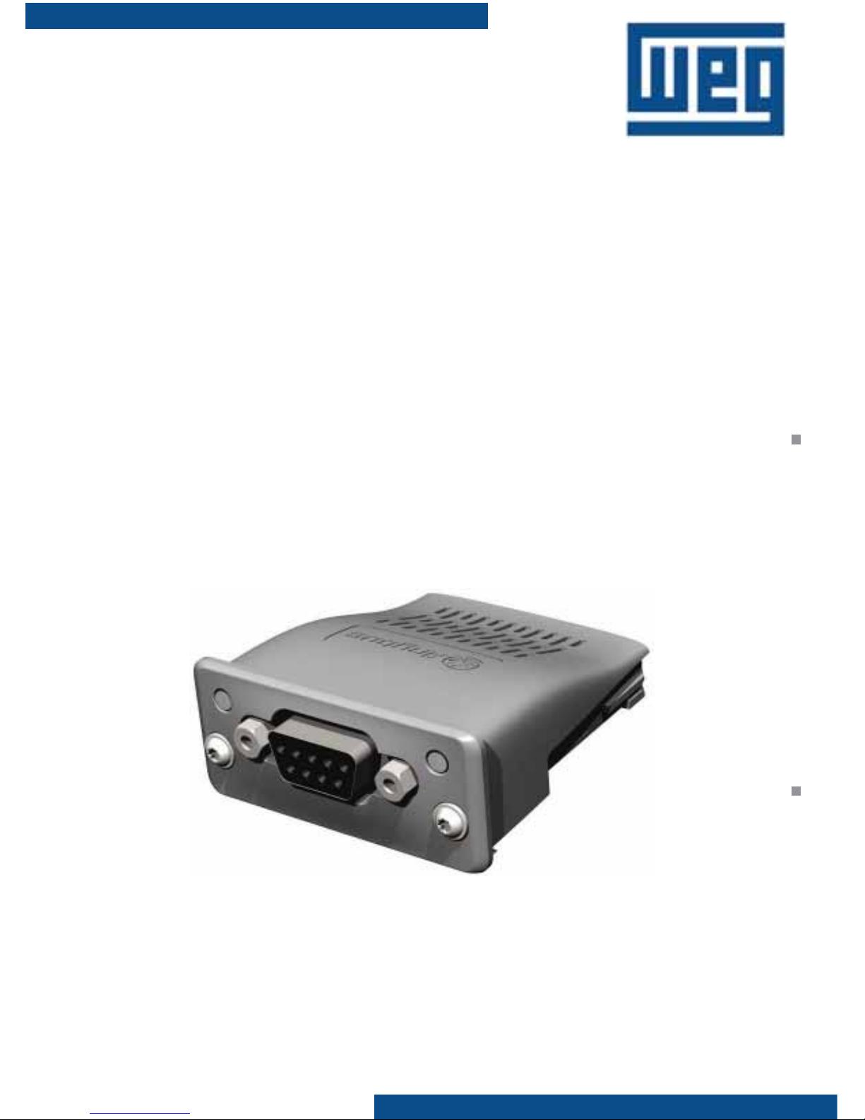
Anybus-CC Module
Módulo Anybus-CC
Módulo Anybus-CC
Installation, Confi guration Guía de Instalación, Guia de Instalação,
and Operation Guide Confi guración y Operación Confi guração e Operação
Page 2

Anybus-CC Accessory Module
Summary English
l. Safety Information ..........................................................1
ll. General Information ......................................................1
lll. Package Contents .........................................................1
1. Accessories Installation ..................................................1
2. Configurations ..............................................................3
3. Operation .................................................................... 3
Tarjetas de Interface Anybus-CC
Indice Español
I. Informaciones de Seguridad ............................................4
ll. Informaciones Generales ...............................................4
lll. Contenido del Embalaje ................................................4
1. Instalación de los Acessories ..........................................4
2. Configuraciones ...........................................................6
3. Puesta en Marcha ......................................................... 6
Módulos de Interface Anybus-CC
Índice Português
l. Informações de Segurança ..............................................7
ll. Informações Gerais ....................................................... 7
lll. Conteúdo da Embalagem ............................................. 7
1. Instalação dos Acessórios ..............................................7
2. Configurações .............................................................. 9
3. Colocação em Funcionamento ...................................... 9
Page 3

1
English
Installation, Configuration and Operation Guide
Anybus-CC Accessory Module
I. SAFETY INFORMATION
All safety procedures described in the manual should be followed.
ll. GENERAL INFORMATION
This is a guide for the installation, configuration and operation of the Anybus-CC
accessories. These modules make different interfaces/protocols available for the product,
as for example:
- PROFIBUSDP-05
- DEVICENET-05
- ETHERNET/IP-05
- RS232-05
- RS485-05
lll. PACKAGE CONTENTS
- Accessory module in anti-static packaging.
- Installation, configuration and operation guide.
- torx screwdriver.
1. ACCESSORIES INSTALLATION
The accessories are installed directly into slots on the CFW-11 control module.
Figure 1: Accessory slot identification
- slot1: white
- slot2: yellow
- slot3: green
- slot4: Anybus
Page 4
2
English
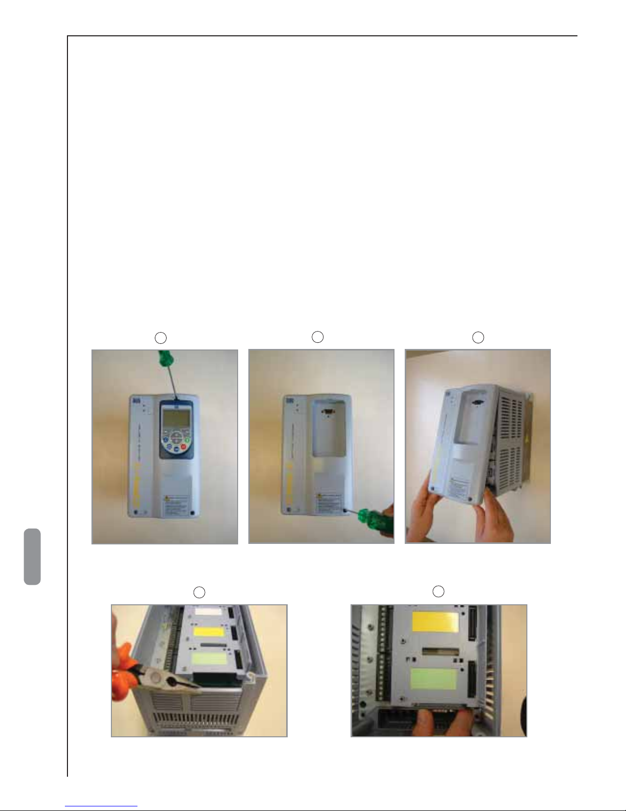
For correct installation of the communication modules, follow the steps below:
Step 1 With the drive de-energized, remove the front cover of the CFW-11
(figure 2).
Step 2 With the help of pliers, remove the fins located in the lower part of the drive.
(figure 3(a)).
Step 3 Carefully insert the module in slot 4. T o do this, gently press the Anybus-CC
module against the control card of the drive and slide it in the direction of
the connector, observing the fit through the opening in the plastic cover of
the control card (figure 3(b)).
Step 4 Make sure that the entire base of the Anybus-CC is in contact with the control
card, and that the module locks are properly inserted in the borders of the
card (figure 3(c)).
Step 5 Tighten the screws of the module using the supplied torx screwdriver
(figure 3(d)).
Figure 2: Removal of front cover
Figure 3: Accessory installation in the slot
b
c
a
b
a
Page 5

3
English
2. CONFIGURATIONS
For detailed information regarding network installation, parameterization, protocols
and operation of the CFW-11, using the Anybus - CC modules, see the Anybus -CC
Communication Manual, supplied in the CD-ROM that comes with the drive.
3. OPERATION
Step 1 After installing the accessory, energize the drive.
Step 2 Make sure the accessory has been correctly installed, observing the value
of parameter P0723. This parameter should indicate the model of the
Anybus-CC module, according to the installed interface/protocol.
Parameter P0723 can be accessed through the following menu on the
HMI:
01 PARAMETER GROUPS
49 Comunication
114 Anybus
Figura 3: Accessory installation in the slot
d
c
Page 6

4
Español
Guía de Instalación, Configuración y Operación
Tarjetas de Interface Anybus-CC
I. INFORMACIONES DE SEGURIDAD
Todos los procedimientos de seguridad descriptos en el manual deben ser seguidos.
ll. INFORMACIONES GENERALES
Este guía orienta en la instalación, configuración y operación de los accesorios
Anybus-CC. Estos módulos ofrecen diferentes interfaces/protocolos para el producto,
como por ejemplo:
- PROFIBUSDP-05
- DEVICENET-05
- ETHERNET/IP-05
- RS232-05
- RS485-05
lll. CONTENIDO DEL EMBALAJE
- Módulo de accesorio en embalaje antiestático.
- Guía de instalación, configuración y operación.
- Llave torx.
1. INSTALACIÓN DE LOS ACCESORIOS
Los accesorios son instalados directamente en “slot” ubicado sobre el módulo
de control del CFW-11.
Figura 1: Identificación de “slots” para accesorios
- slot1: blanco
- slot2: amarillo
- slot3: verde
- slot4: Anybus
Page 7

5
Español
Figura 2: Quitando la tapa frontal
Figura 3: Instalación del accesorio en el “slot”
Para la correcta instalación de los módulos de comunicación ejecute los pasos
que siguen:
Paso 1 Con el convertidor desenergizado, quite la tapa frontal del CFW-11
(figura 2).
Paso 2 Con ayuda de un alicate, quite las aletas ubicadas en la parte inferior del
convertidor (figura 3(a)).
Paso 3 Encaje cuidadosamente el módulo en el “slot 4”. P ara eso, presione suave-
mente el módulo Anybus-CC contra la tarjeta de control del convertidor y
desplace lo mismo en dirección al conector, observando el encaje a través
de la abertura en la cubierta plástica de la tarjeta de control (figura 3(b)).
Paso 4 Certifíquese que toda base del módulo Anybus-CC este en contacto con
la tarjeta de control, y las trabas del módulo estén debidamente encajadas
en la orilla de la tarjeta (figura 3(c)).
Paso 5 Apriete los tornillo del módulo con ayuda de la llave torx suministrada
(figura 3(d)).
b
c
a
b
a
Page 8

6
Español
2. CONFIGURACIONES
Informaciones detalladas sobre instalación de la red, parametrización, protocolos
y operación del CFW-11 utilizando los módulos Anybus -CC, consulte el Manual
de la Comunicación Anybus-CC, suministrado en el CD -ROM que acompaña el
convertidor de frecuencia.
3. PUESTA EN MARCHA
Paso 1 Después de instalado el accesorio, alimentar el convertidor.
Paso 2 Verifique si el accesorio fue correctamente instalado, observando el valor
del parámetro P0723. Este deberá indicar el modelo del módulo AnybusCC de acuerdo con la interface/protocolo instalado.
El parámetro P0723 puede ser accesado a través del siguiente menú en
la IHM:
01 GRUPOS PARÁMETROS
49 Comunicación
114 Anybus
Figura 3: Instalación del accesorio en el “slot” (cont.)
d
c
Page 9

7
Português
Guia de Instalação, Configuração e Operação
Módulos de Interface Anybus-CC
I. INFORMAÇÕES DE SEGURANÇA
Todos os procedimentos de segurança descritos no manual devem ser seguidos.
ll. INFORMAÇÕES GERAIS
Este guia orienta na instalação, configuração e operação dos acessórios Anybus-CC.
Estes módulos disponibilizam diferentes interfaces/protocolos para o produto, como por
exemplo:
- PROFIBUSDP-05
- DEVICENET-05
- ETHERNET/IP-05
- RS232-05
- RS485-05
lll. CONTEÚDO DA EMBALAGEM
- Módulo de acessório em embalagem anti-estática.
- Guia de instalação, configuração e operação.
- Chave torx.
1. INSTALAÇÃO DOS ACESSÓRIOS
Os acessórios são instalados diretamente em slot localizado no módulo de
controle do CFW-11.
Figura 1: Identificação de slots para acessórios
- slot1: branco
- slot2: amarelo
- slot3: verde
- slot4: Anybus
Page 10

8
Português
Figura 2: Remoção da tampa frontal
Figura 3: Instalação do acessório no slot
b
a
Para a correta instalação dos módulos de comunicação execute os passos a
seguir:
Passo 1 Com o inversor desenergizado, retire a tampa frontal do CFW-11
(figura 2).
Passo 2 Com auxílio de um alicate, remova as aletas localizadas na parte inferior
do inversor (figura 3(a)).
Passo 3 Encaixe cuidadosamente o módulo no slot 4. Para isto, pressione sua-
vemente o módulo Anybus-CC contra o cartão de controle do inversor
e deslize este em direção ao conector, observando o encaixe através da
abertura na cobertura plástica do cartão de controle (figura 3(b)).
Passo 4 Certifique-se que toda base do módulo Anybus-CC esteja em contato
com o cartão de controle, e as travas do módulo estejam devidamente
encaixadas na borda do cartão (figura 3(c)).
Passo 5 Aperte os parafusos do módulo com auxílio da chave torx fornecida
(figura 3(d)).
b
c
a
Page 11

9
Português
2. CONFIGURAÇÕES
Informações detalhadas sobre instalação da rede, parametrização, protocolos
e operação do CFW-11 utilizando os módulos Anybus - CC, consulte o Manual da
Comunicação Anybus-CC, fornecido no CD-ROM que acompanha o inversor.
3. COLOCAÇÃO EM FUNCIONAMENTO
Passo 1 Depois de instalado o acessório, energize o inversor.
Passo 2 V erifique se o acessório foi corretamente instalado, observando o valor do
parâmetro P0723. Este deverá indicar o modelo do módulo Anybus-CC
de acordo com a interface/protocolo instalado.
O parâmetro P0723 pode ser acesso através do seguinte menu na
HMI:
01 GRUPOS PARÂMETROS
49 Comunicação
114 Anybus
Figura 3: Instalação do acessório no slot (cont.)
d
c
Page 12

www.weg.net
0899.5648_E/S/P1
 Loading...