

Page 1

LINK 710
Installation Guide
Page 2

Contents
Read me first. . . . . . . . . . . . . . . . . . . . . . . . . . . . . . . . . . . . . . . . . . . . . . . . . . . . . 4
Congratulations. . . . . . . . . . . . . . . . . . . . . . . . . . . . . . . . . . . . . . . . . . . . . . . . . . . . . . . . 4
What’s in the box. . . . . . . . . . . . . . . . . . . . . . . . . . . . . . . . . . . . . . . . . . . . . . . . . . 5
What you need for the installation. . . . . . . . . . . . . . . . . . . . . . . . . . . . . . . . . . . . . . . . 6
Safety first. . . . . . . . . . . . . . . . . . . . . . . . . . . . . . . . . . . . . . . . . . . . . . . . . . . . . . . . 7
Important safety notices and warnings. . . . . . . . . . . . . . . . . . . . . . . . . . . . . . . . . . . . 7
Connection overview. . . . . . . . . . . . . . . . . . . . . . . . . . . . . . . . . . . . . . . . . . . . . . . 9
Connection overview: Power/CAN cable. . . . . . . . . . . . . . . . . . . . . . . . . . . . . . . . . . . 9
Connection overview: 12 PIN IO cable. . . . . . . . . . . . . . . . . . . . . . . . . . . . . . . . . . . . . 10
Connection overview: 1 wire. . . . . . . . . . . . . . . . . . . . . . . . . . . . . . . . . . . . . . . . . . . . . 10
Connecting to the CAN bus. . . . . . . . . . . . . . . . . . . . . . . . . . . . . . . . . . . . . . . . . 11
Connecting to power. . . . . . . . . . . . . . . . . . . . . . . . . . . . . . . . . . . . . . . . . . . . . . 12
Choosing the correct position. . . . . . . . . . . . . . . . . . . . . . . . . . . . . . . . . . . . . . 13
Mounting the LINK 710. . . . . . . . . . . . . . . . . . . . . . . . . . . . . . . . . . . . . . . . . . . . . 15
Attaching the holder using the adhesive strip. . . . . . . . . . . . . . . . . . . . . . . . . . . . . . 16
Attaching the holder using self-tapping screws. . . . . . . . . . . . . . . . . . . . . . . . . . . . 16
Mounting the external GPS antenna. . . . . . . . . . . . . . . . . . . . . . . . . . . . . . . . . . . . . . . 17
Testing operation. . . . . . . . . . . . . . . . . . . . . . . . . . . . . . . . . . . . . . . . . . . . . . . . . 19
Power or Ignition test. . . . . . . . . . . . . . . . . . . . . . . . . . . . . . . . . . . . . . . . . . . . . . . . . . . 19
Mobile network reception test. . . . . . . . . . . . . . . . . . . . . . . . . . . . . . . . . . . . . . . . . . . 19
Activating the LINK 710. . . . . . . . . . . . . . . . . . . . . . . . . . . . . . . . . . . . . . . . . . . 20
Diagnostics. . . . . . . . . . . . . . . . . . . . . . . . . . . . . . . . . . . . . . . . . . . . . . . . . . . . . . 21
Monitoring operation. . . . . . . . . . . . . . . . . . . . . . . . . . . . . . . . . . . . . . . . . . . . . . . . . . . 21
Support. . . . . . . . . . . . . . . . . . . . . . . . . . . . . . . . . . . . . . . . . . . . . . . . . . . . . . . . . . . . . . 22
Resetting the LINK 710. . . . . . . . . . . . . . . . . . . . . . . . . . . . . . . . . . . . . . . . . . . . 23
2
Page 3

Restarting your LINK 710. . . . . . . . . . . . . . . . . . . . . . . . . . . . . . . . . . . . . . . . . . . . . . . 23
Resetting your LINK 710 to factory settings. . . . . . . . . . . . . . . . . . . . . . . . . . . . . . . 23
Technical data. . . . . . . . . . . . . . . . . . . . . . . . . . . . . . . . . . . . . . . . . . . . . . . . . . . 24
Appendix: Using the I/O connector. . . . . . . . . . . . . . . . . . . . . . . . . . . . . . . . . . 27
Wiring digital inputs. . . . . . . . . . . . . . . . . . . . . . . . . . . . . . . . . . . . . . . . . . . . . . . . . . . . 27
Wiring the digital output. . . . . . . . . . . . . . . . . . . . . . . . . . . . . . . . . . . . . . . . . . . . . . . . 28
Using the IN and OUT for changing the logbook mode - 710. . . . . . . . . . . . . . . . 29
Using the input IN for changing the logbook mode. . . . . . . . . . . . . . . . . . . . . . . . . 29
Using the input IN for idle time reporting. . . . . . . . . . . . . . . . . . . . . . . . . . . . . . . . . 30
Addendum. . . . . . . . . . . . . . . . . . . . . . . . . . . . . . . . . . . . . . . . . . . . . . . . . . . . . . . 31
Important Safety Notices and Warnings. . . . . . . . . . . . . . . . . . . . . . . . . . . . . . . . . . . 31
Prohibited uses. . . . . . . . . . . . . . . . . . . . . . . . . . . . . . . . . . . . . . . . . . . . . . . . . . . . . . . . 32
CE mark and Radio Equipment Directive for LINK 710. . . . . . . . . . . . . . . . . . . . . . 32
EU Specific Absorption Rate (SAR) compliance. . . . . . . . . . . . . . . . . . . . . . . . . . . . 32
Button battery warning. . . . . . . . . . . . . . . . . . . . . . . . . . . . . . . . . . . . . . . . . . . . . . . . . 32
Environmental and Battery information. . . . . . . . . . . . . . . . . . . . . . . . . . . . . . . . . . . 32
Operating temperature. . . . . . . . . . . . . . . . . . . . . . . . . . . . . . . . . . . . . . . . . . . . . . . . . 33
WEEE – e-waste disposal. . . . . . . . . . . . . . . . . . . . . . . . . . . . . . . . . . . . . . . . . . . . . . . 33
How Webfleet Solutions uses your information. . . . . . . . . . . . . . . . . . . . . . . . . . . . 33
Exposure limits. . . . . . . . . . . . . . . . . . . . . . . . . . . . . . . . . . . . . . . . . . . . . . . . . . . . . . . . 34
Mobile networks. . . . . . . . . . . . . . . . . . . . . . . . . . . . . . . . . . . . . . . . . . . . . . . . . . . . . . . 34
Triman logo. . . . . . . . . . . . . . . . . . . . . . . . . . . . . . . . . . . . . . . . . . . . . . . . . . . . . . . . . . . 34
Technical Specifications. . . . . . . . . . . . . . . . . . . . . . . . . . . . . . . . . . . . . . . . . . . . . . . . 34
Model numbers. . . . . . . . . . . . . . . . . . . . . . . . . . . . . . . . . . . . . . . . . . . . . . . . . . . . . . . . 35
This document. . . . . . . . . . . . . . . . . . . . . . . . . . . . . . . . . . . . . . . . . . . . . . . . . . . . . . . . 35
WEBFLEET Telematics Service Platform. . . . . . . . . . . . . . . . . . . . . . . . . . . . . 35
Accessories supplied with this device. . . . . . . . . . . . . . . . . . . . . . . . . . . . . . . 35
Accessories not supplied with this device. . . . . . . . . . . . . . . . . . . . . . . . . . . . 35
Terms and conditions: Limited warranty and EULA reference. . . . . . . . . . . 35
Copyright notices. . . . . . . . . . . . . . . . . . . . . . . . . . . . . . . . . . . . . . . . . . . . . . . . 36
Bluetooth® . . . . . . . . . . . . . . . . . . . . . . . . . . . . . . . . . . . . . . . . . . . . . . . . . . . . . . . . . . . 36
Copyright (c) 2018 - Tcl/Tk - Regents of the University of California, Sun
Microsystems, Inc., Scriptics Corporation, and other parties. . . . . . . . . . . . . . . . . 36
Webfleet Solutions Limited Warranty. . . . . . . . . . . . . . . . . . . . . . . . . . . . . . . . 37
3
Page 4

Read me first
Congratulations
You have chosen the LINK 710, a core hardware component from WEBFLEET. With
WEBFLEET you are always connected to your vehicles out on the road in a smart and
easy way.
LINK 710 is a GPS receiver and mobile network module in one unit, always providing
the vehicle’s current position.
When used with a compatible Driver Terminal, you can easily handle orders, as well as
text and status messages. You can receive traffic information, and you are warned
when you are driving or cornering too fast. And you can get information about how
much fuel you have used.
4
Page 5
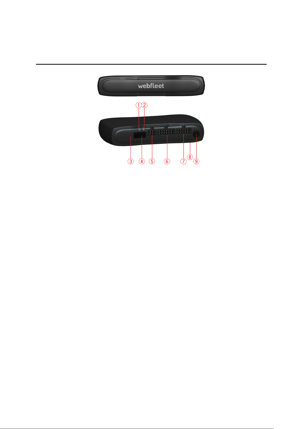
What’s in the box
▪ LINK 710
1. Yellow LED - connection status indicator.
2. Green LED - system status indicator.
3. Reset button.
4. Service/Update Mini-USB-cable connector.
5. 1-Wire-Interface.
6. I/O-cable connector.
7. Power/CAN connector.
8. CAN DIP switch (sealed).
5
Page 6
9. GPS antenna connector.
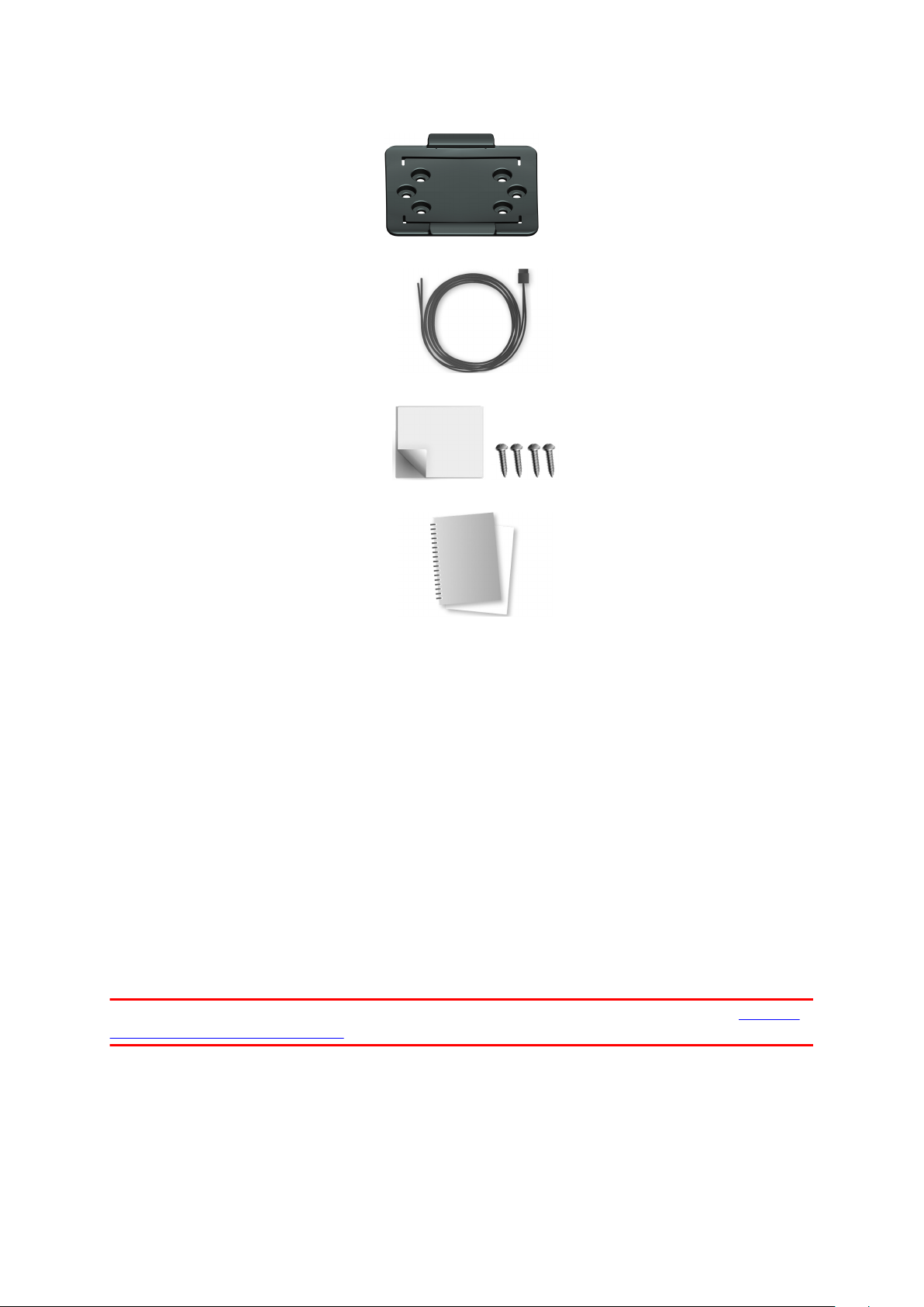
▪ Holder
▪ Power/CAN cable
▪
Fixings - 1 adhesive strip, 4 self-tapping screws and a cleaning tissue
▪ Basic installation guide
What you need for the installation
Before starting the installation of your LINK 710, read the installation instructions and
the safety notices and warnings carefully and make sure you have the following:
▪ The Contract Confirmation letter including the Activation Code.
▪ A device with internet connection and software to scan and read QR codes.
▪ The QR code of the LINK 710, which is printed on a sticker on the bottom of the
device.
▪ The login credentials to the LINK Toolkit app.
▪ All parts contained in the box.
▪ A connection to the vehicle’s power supply that is fused with max. 10A.
▪ A place with a clear view of the sky where you can move your vehicle to check
GPS reception.
▪ A Driver Terminal that is compatible with LINK 710* - optional.
* To check available LINK 710 accessories or device compatibility please visit https://
www.webfleet.com/products
6
Page 7

Safety first
Important safety notices and warnings
Important: Read the following safety instructions carefully. Read the instructions in
this document carefully.
Webfleet Solutions accept no liability for damage that results from disregarding the
safety instructions. This document is part of the product. Keep it in a safe place. If you
pass the unit on to a new user, make sure you give them this document as well.
Positioning
Position the device in such a way that it doesn’t block or interfere with your view of
the road, the controls in your vehicle, or the rear-view mirrors and airbags.
Danger of explosion
Parts of this product can cause sparks that can lead to explosions. This may endanger
human health and life. Do not use the unit in areas with high risk of explosion. When
using this product in a vehicle fuelled by liquefied gas, follow the safety regulations of
the country in which the vehicle is operated.
Damage caused through improper installation
The installation and initial operation of the unit must be performed by authorised
personnel only, for example, a qualified radio dealer or an automotive electronics
workshop.
Risk of injury in case of accidents
Do not mount the unit or accessories in the inflation area of airbags or in the impact
area for the head or knees. Choose an installation location that will avoid interference
with displays, safety equipment and controls.
Damage to the chassis
Make sure you do not drill into parts of the chassis that have structural or securityrelated functions. This is because you cannot be certain that they will function
properly after modification.
Risk of fire
Make sure you do not drill into covered wiring harnesses, fuel lines or similar
components. Drilling into these can cause fire.
Repair and replacement
Repairs must be carried out by authorised and qualified personnel only. Never replace
damaged parts of the unit yourself. Send the defective unit to Webfleet Solutions for
repair. Only the qualified staff of Webfleet Solutions are authorised to repair or
replace parts.
7
Page 8

Damage to the device
Short-circuits inside the unit can be caused by contact with water or other liquids.
The unit may be damaged by contact with water. Use and store the unit in an area
protected from water.
8
Page 9
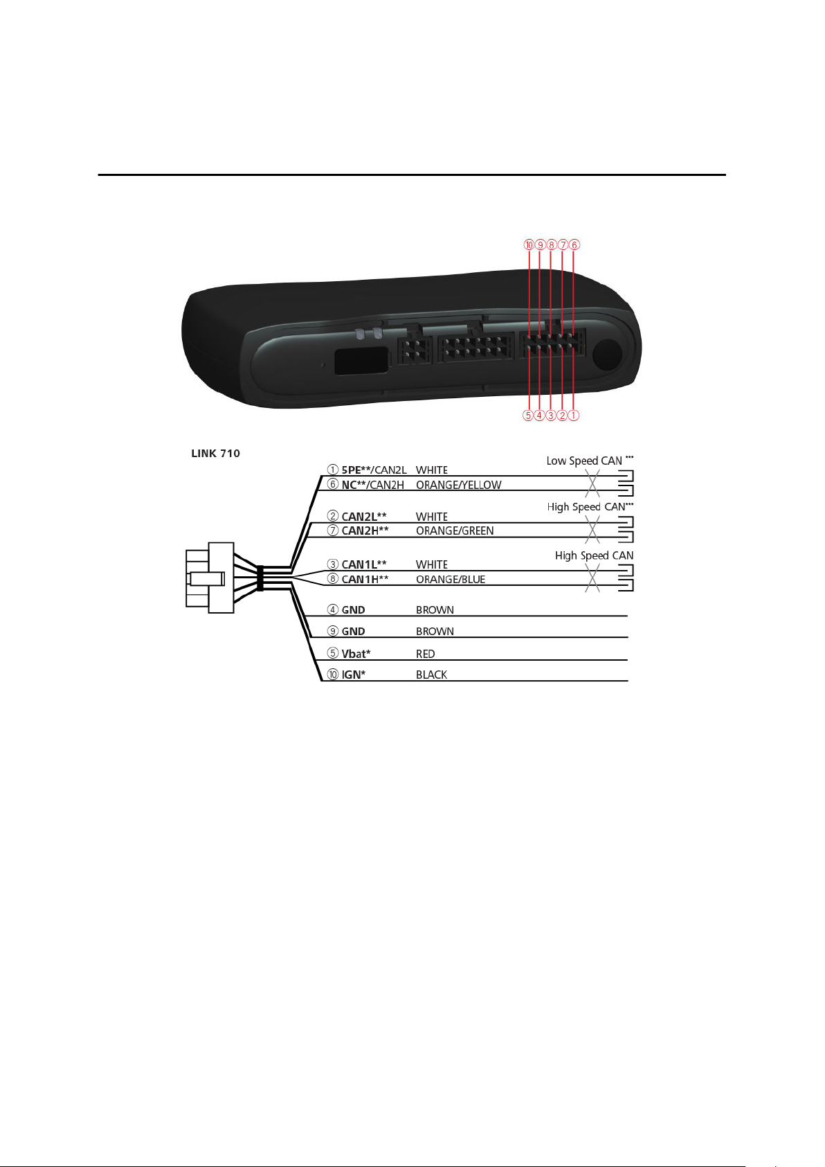
Connection overview
Connection overview: Power/CAN cable
* Make sure this wire is fused with max. 10A.
** Twisted pair. Loose ends of CAN L/CAN H wires must be protected against short
circuits. Separate by using a heat shrink tube.
*** Only one of the CAN2 ports can be used.
9
Page 10
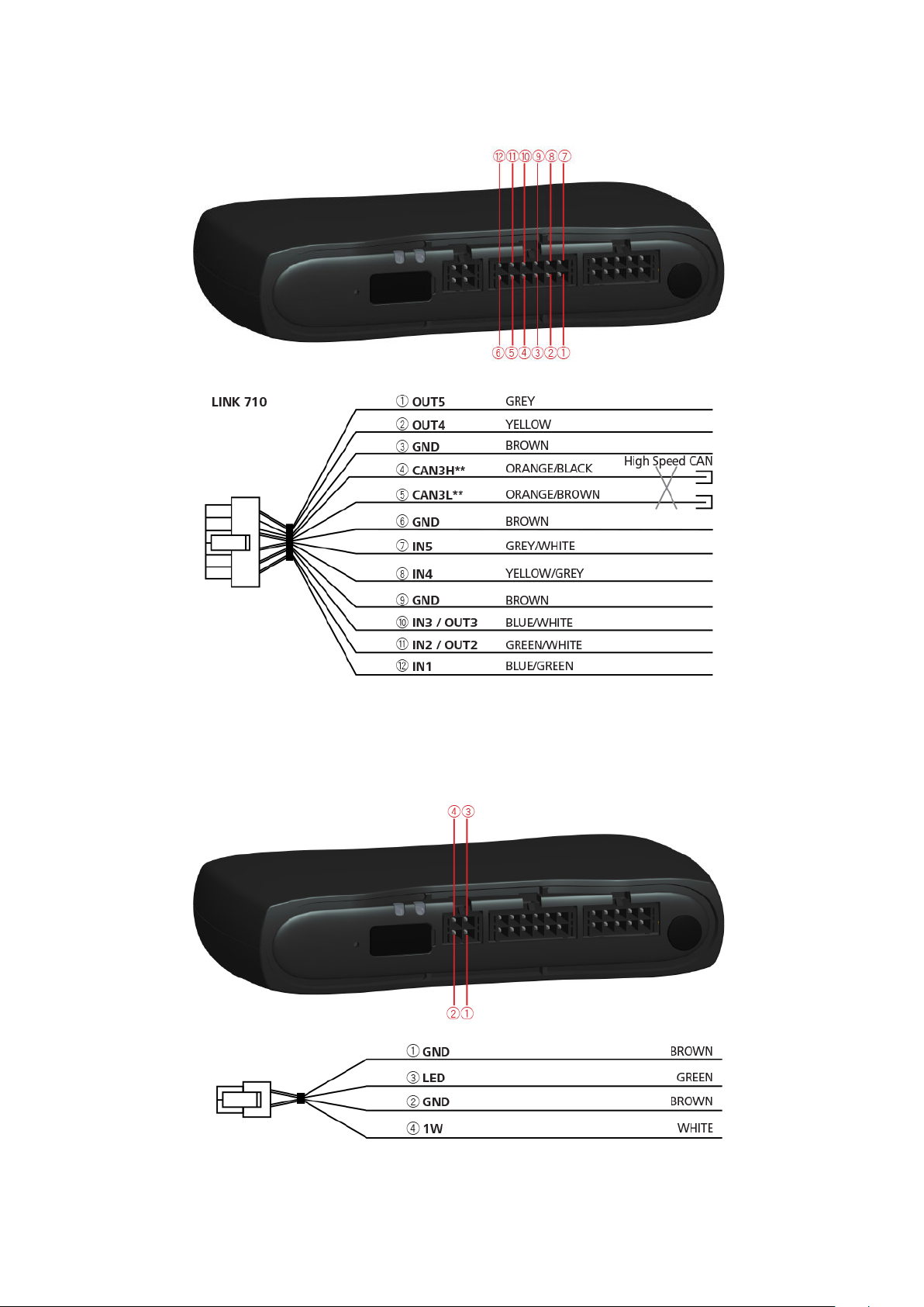
Connection overview: 12 PIN IO cable
** Twisted pair. Loose ends of CAN L/CAN H wires must be protected against short
circuits. Separate by using a heat shrink tube.
Connection overview: 1 wire
10
Page 11

Connecting to the CAN bus
Please refer to the Webfleet Solutions tooling for the CAN configuration of your
specific vehicle.
Important! If you need to alter the setting of the CAN DIP switch, re-cover the
switches using the red seal, taking care to close the rubber cover completely.
Tips for the installation
▪ For direct connection to the CAN bus select the wire to be as short as possible
and needed. Do not wind the CAN wires.
▪ Always read the vehicle manufacturer manual for working on the electric BUS
system of the vehicle.
▪ Do not cut the vehicle's wire harness but use a special wire stripper.
▪ If you have to remove the insulation of wires that are close to each other (e.g. CAN
wires), make sure that the places where the insulation is removed are at least 2 cm
away from each other to avoid short circuits.
▪ After the installation, places with removed insulation need to be secured with
electrical insulation tape (if possible with heat shrink) and afterwards with a layer
of fabric insulation tape.
Note: You can use the LINK CAN Sensor 100 accessory to establish a contactless
connection to the CAN 1 or CAN 2 bus.
11
Page 12
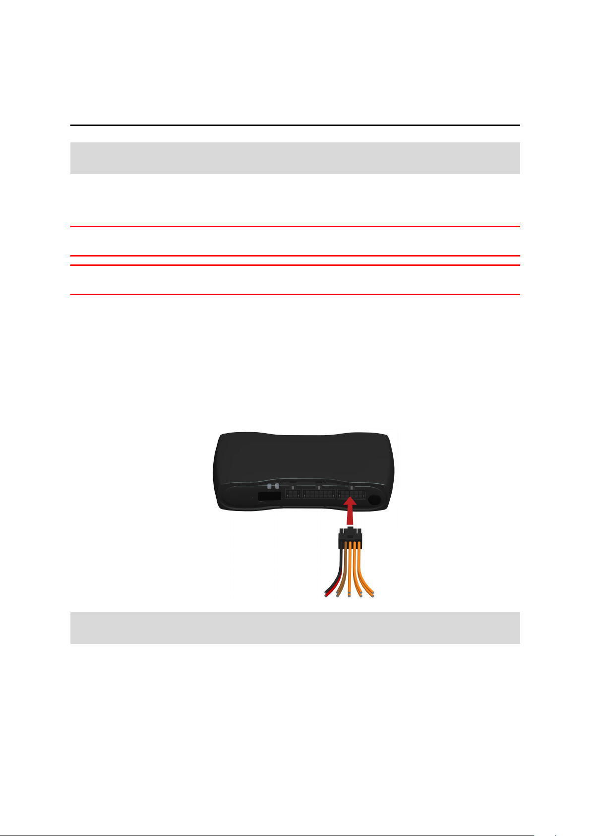
Connecting to power
Note: If want to connect the LINK CAN Sensor 100 to your LINK 710, please use the
Data/Power Cable supplied with the LINK CAN Sensor 100.
Connect the LINK 710 to the vehicle power supply with the standard vehicle voltage
(12 V/24 V). Do not connect to a voltage converter. The three wires GND, IGN and
PWR+ (supply voltage) must be connected.
Important: Follow the order of connecting the wires as described below. First connect
the wires then insert the plug into the LINK 710.
If you have inserted the plug into the LINK 710 first, you must connect the GND wire
before you connect the PWR+ wire and the IGN wire as described below.
1. Connect the GND wire (brown) to ground (clamp 31).
2. Connect the PWR+ wire (red) to the carry current (clamp 30).
The connection must be fused with max. 10A. If not, fuse the PWR+ wire with one
2A fast blow fuse.
3. Connect the IGN wire (black) to ignition (clamp 15).
The connection must be fused with max. 10A. If not, fuse the IGN wire with one 2A
fast blow fuse.
4. Insert the Power/CAN plug into the power cable connector.
If you need to disconnect the wires while the Power/CAN plug is plugged in the
LINK 710 make sure you disconnect the GND wire last.
12
Page 13
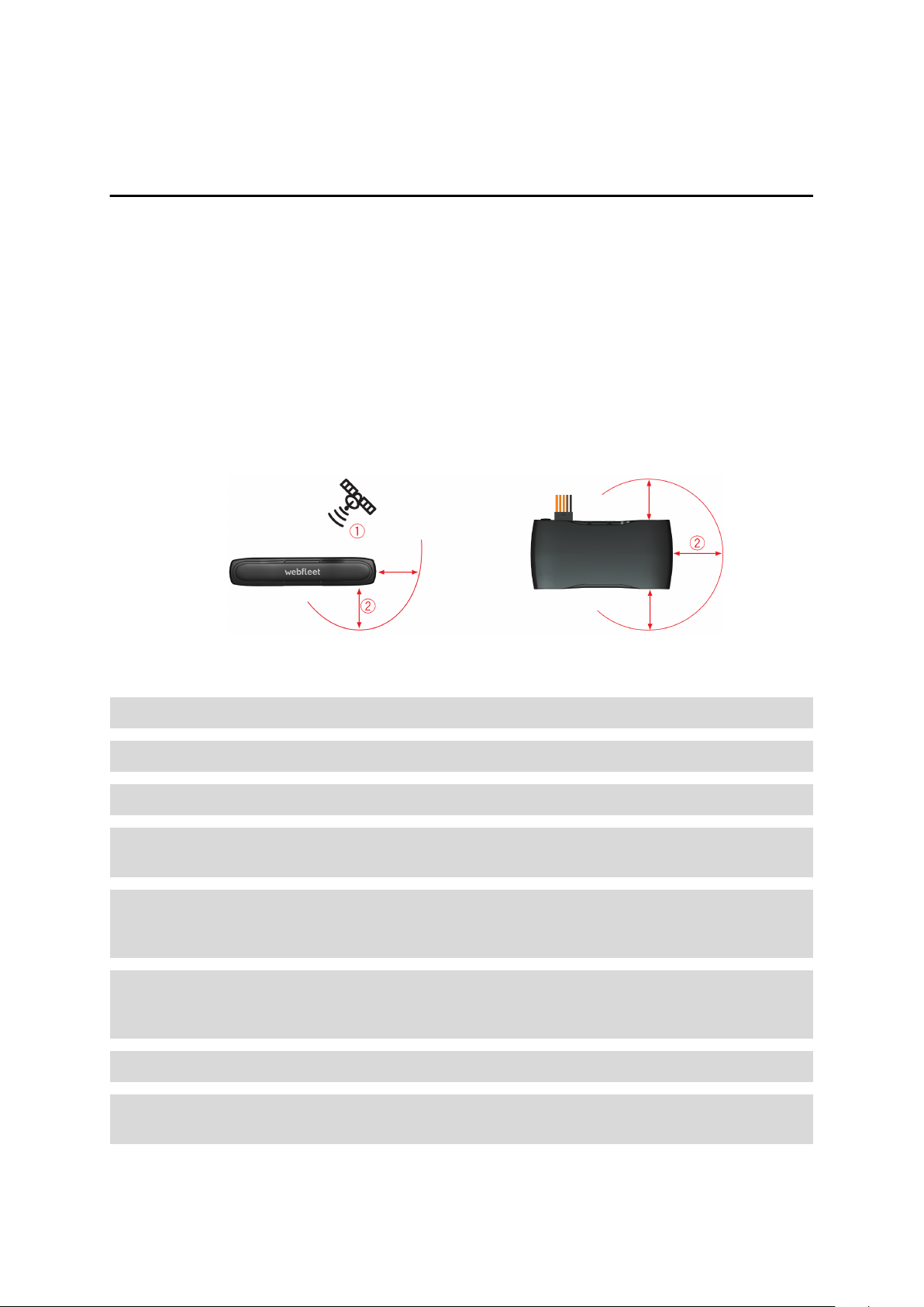
Choosing the correct position
First you need to choose the correct position in which to install your LINK 710.
Take the following into consideration:
▪ Do not expose the LINK 710 to direct sunlight and/or high temperature for long
periods to ensure proper operation.
▪ To ensure GPS reception using the integrated GPS receiver, the top of the device
must not be obstructed by metal items. For more flexibility with regards to
installation we recommend using the external GPS antenna from Webfleet
Solutions.
▪ To ensure GSM/GPRS reception using the integrated GSM/GPRS antenna, the
device must not be placed on or surrounded by metal items such as the vehicle’s
coachwork closer than 5 cm (2 inches) and the top side must not be obstructed by
metal items.
1. Top side of the device must not be obstructed by metal items.
2. Keep minimum distance of 5 cm (2 inches) to metal items.
The device must be positioned with the top side pointing to the sky.
The device must be positioned so that it is unobstructed by metal objects.
The device must not interfere with clear vision for the driver.
Tinted metallised windscreens or those with integrated filament heating may block
GPS reception.
Place the unit a minimum of 5 cm (2 inches) distance to the coachwork or other
metal items, so that optimal mobile network transmission and GPS reception is
ensured.
The unit must be placed on an oil free, dry and clean surface, when using the
adhesive strips. Extreme temperature changes/differences can affect the adhesive
property of the strips.
The device must not be placed inside ventilation ducts.
The device and its cable must not block or impede vent controls, in the case the
device is mounted near ventilation ducts.
13
Page 14

Do not mount the device close to other electrical components in the car like built-in
alarms, gateway, control units, navigation units or to toll collect devices where it
could cause or receive interferences.
Before installing the device, please consider the safety instructions and choose the
correct position.
14
Page 15

Mounting the LINK 710
Your LINK 710 comes with an integrated mobile network antenna and an integrated
GPS antenna. Depending on the position you choose for the installation, you can
install your LINK 710 without an external GPS antenna.
The device must be positioned with the top side pointing to the sky.
The device must be positioned so that it is unobstructed by metal objects.
The device must not interfere with clear vision for the driver.
Tinted metallised windscreens or those with integrated filament heating may block
GPS reception.
Place the unit a minimum of 5 cm (2 inches) distance to the coachwork or other
metal items, so that optimal mobile network transmission and GPS reception is
ensured.
The unit must be placed on an oil free, dry and clean surface, when using the
adhesive strips. Extreme temperature changes/differences can affect the adhesive
property of the strips.
The device must not be placed inside ventilation ducts.
The device and its cable must not block or impede vent controls, in the case the
device is mounted near ventilation ducts.
Do not mount the device close to other electrical components in the car like built-in
alarms, gateway, control units, navigation units or to toll collect devices where it
could cause or receive interferences.
Before installing the device, please consider the safety instructions and choose the
correct position.
The LINK 710 can be attached with the two adhesive strips or the two tapping screws.
15
Page 16
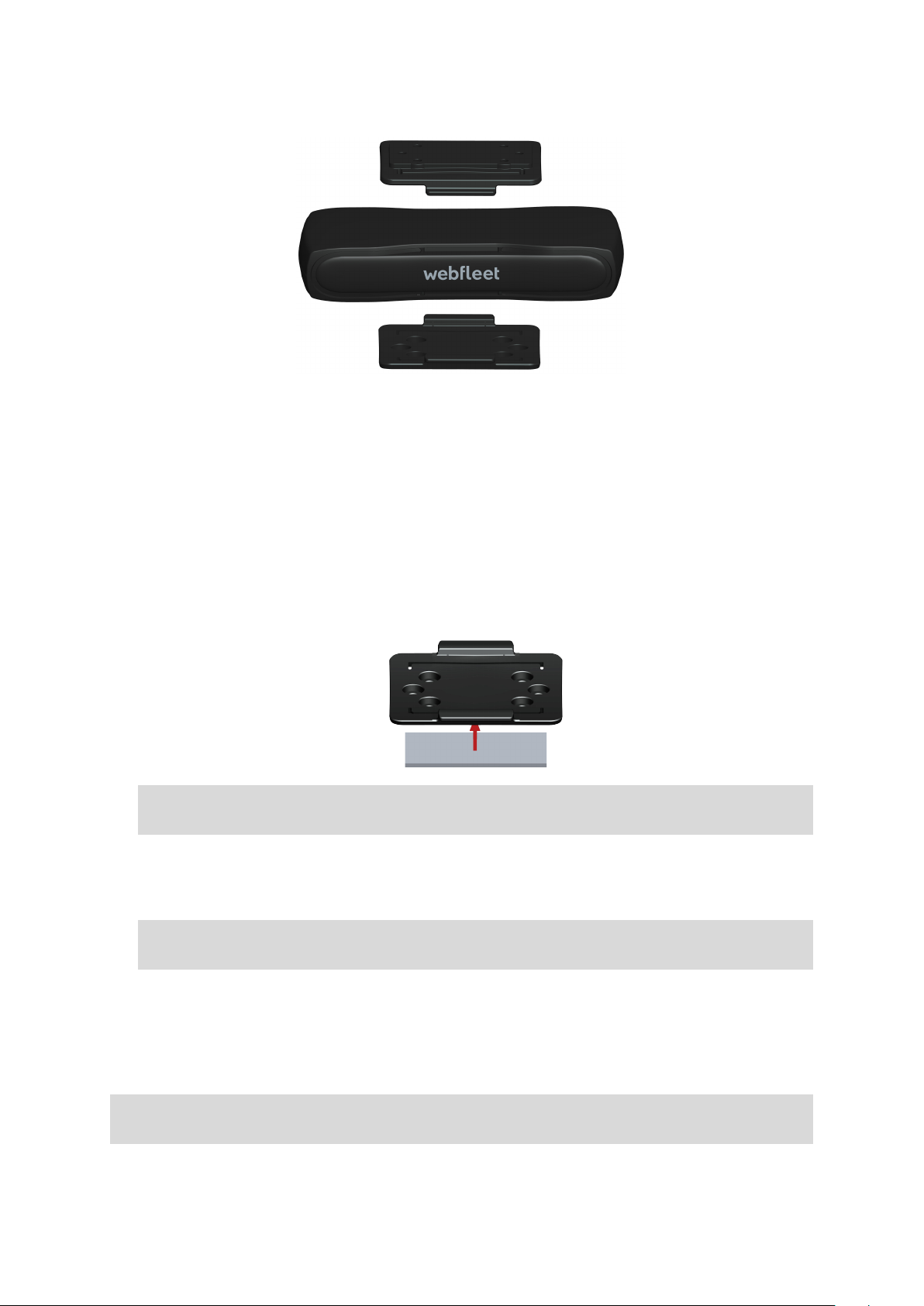
You can attach the holder to the top or to the bottom side of the LINK 710.
Attaching the holder using the adhesive strip
You can use the adhesive strip to fix the LINK 710 to your vehicle. Follow the safety
instructions in this document.
1. Choose a flat surface for accurate positioning of the unit.
Remember, when the LINK 710 is in the holder, it must not be obstructed by metal
objects.
2. Clean the surface with the supplied cleaning tissue, so that the surface is oil free,
dry and clean.
3. Remove the protective film from one side of the strip.
4. Stick the strip to the bottom side of the holder as shown below.
Important: Use the strip only in combination with the holder. Do NOT place the
strip on the serial number sticker of the device.
5. Remove the protective film from the other side of the strip.
6. Place the holder with the adhesive strip on the prepared surface. Press it gently
for a few seconds until it sticks.
Note: The full strength of the strip will be reached after approximately 72 hours
depending on the temperature.
7. Insert the LINK 710 into the holder. Press gently until it clicks into place.
Attaching the holder using self-tapping screws
You can use two self-tapping screws to fix the holder to your vehicle.
Please refer to the list of what's in the box, to check that the self-tapping screws
(3.5 x 16 mm, 1/7 x 5/8 inches) are included in your product package.
1. Choose a flat surface for the LINK 710.
16
Page 17
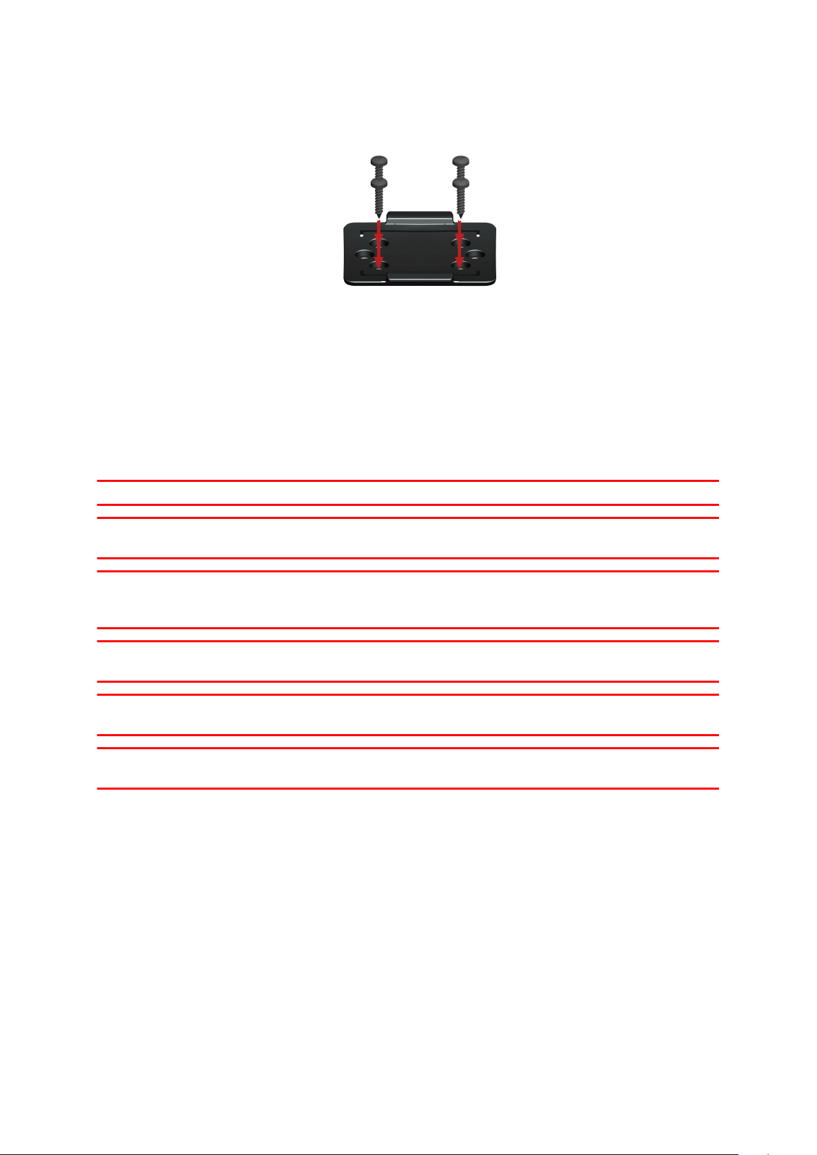
Remember, when the LINK 710 is in the holder, it must not be obstructed by metal
objects.
2. Insert the screws into the corresponding holes in the holder.
3. Tighten the screws.
4. Carefully place the LINK 710 in the holder until it clicks into place.
Mounting the external GPS antenna
If you install the LINK 710 in a position where it has poor GPS reception, you need to
use the external GPS antenna accessory from Webfleet Solutions, Art. no
9UKE.001.00, which comes with an integrated magnet and an adhesive pad. The
external GPS antenna from Webfleet Solutions is not part of the standard LINK 710
product package.
Important
Only use the GPS antenna from Webfleet Solutions, otherwise GPS performance may
be poor or not work at all.
Tinted metallised windscreens or those with integrated filament heating may prevent
good GPS reception. In this case, place the GPS antenna in the rear window or on the
outside of the vehicle.
The magnet of the antenna remains attached to the outside of the car at speeds of up
to 180 km/h.
Install the GPS antenna in a position where it has a clear view of the sky and is
unobstructed by metal objects.
The GPS antenna must be placed with the adhesive pad on an oil free, dry and clean
surface.
17
Page 18
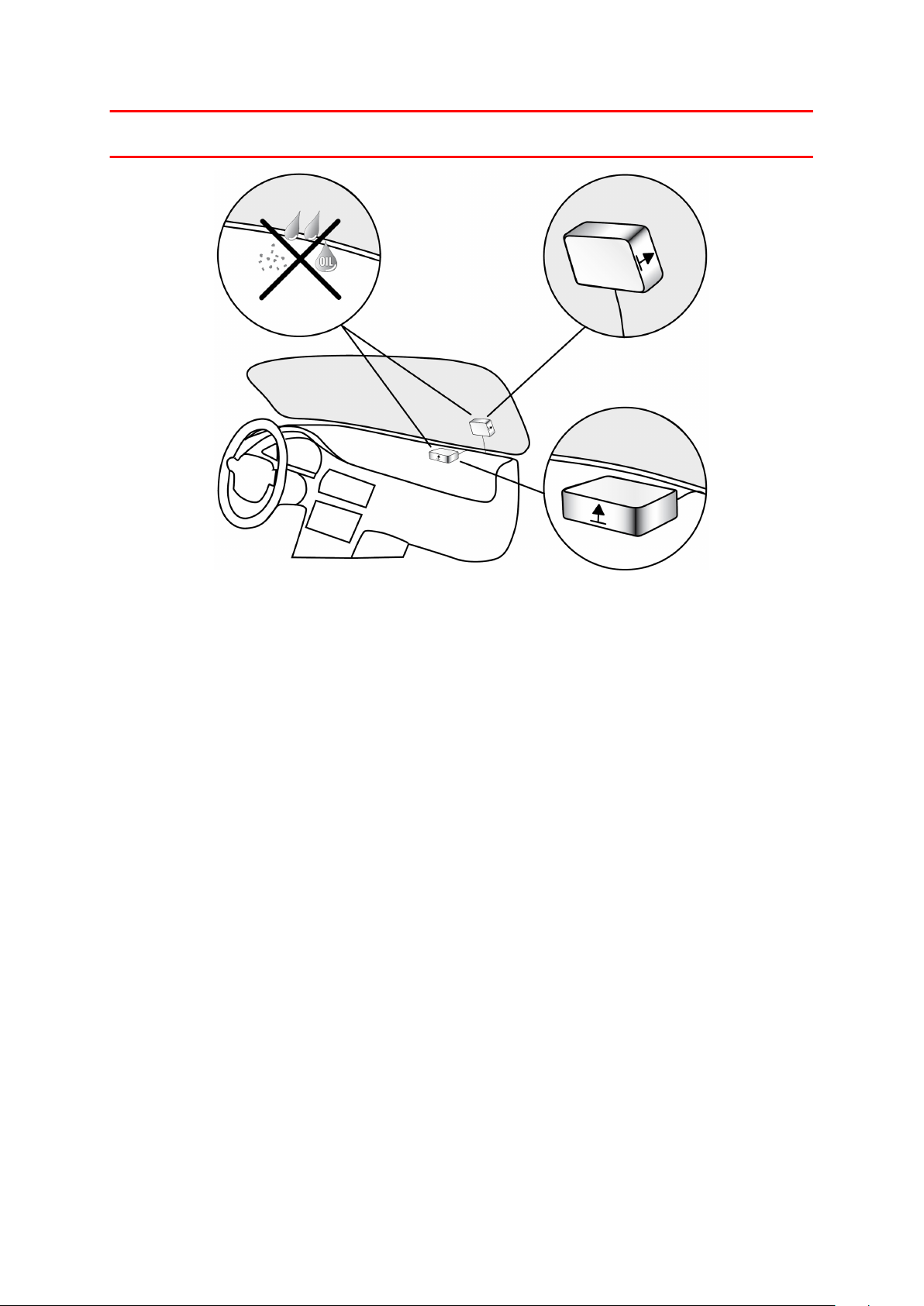
Extreme temperature changes or differences can affect the adhesive property of the
pad.
To mount your external GPS antenna, do the following:
1. Remove the rubber cap from the GPS antenna connector.
2. Insert the plug of the GPS antenna into the GPS antenna connector on the LINK
710.
3. Prepare a smooth, clean, oil free and dry surface on the windscreen.
4. Attach the antenna to the prepared surface so that the top side has a clear view of
the sky. Either locate a smooth metal surface or use the extra adhesive pad.
18
Page 19

Testing operation
In addition to the tests described below you can also test the operation of your LINK
710 using the LINK Toolkit app.
Power or Ignition test
Before testing the connection to power and to the ignition make sure you have
properly carried out the installation.
1. Check all connections to your LINK 710 device (wires, fuses etc.).
2. Turn off the ignition.
The green LED should be off and then go on every 3 seconds.
3. Turn on the ignition.
The green LED should be on and then go off every 3 seconds. If the device is
already activated, the green LED should be on all the time.
If the LED does not perform as described, monitor the LEDs for diagnostics .
Mobile network reception test
For this test, you may need to move the vehicle to a location with a clear view of the
sky, to make sure that you have adequate GPS and mobile network reception.
For this test put your LINK 710 device in the position where you want to fix it.
1. Turn on the ignition.
2. Look at the yellow LED. It should be on and then go off every 3 seconds.
As soon as the device has established a connection to WEBFLEET the yellow LED
stays on all the time.
If the LED keeps flashing for longer than 10 minutes, monitor the LEDs for
diagnostics .
19
Page 20

Activating the LINK 710
You can use the LINK Toolkit app to activate your LINK 710 device.
To go to the online installation tool scan the QR code printed on the bottom of your
LINK 710 device. To obtain access credentials for the online installation tool please
contact Webfleet Solutions or your fleet manager.
Make sure you have the following:
▪ The Contract Confirmation letter including the Activation Code.
▪ A device with internet connection and software to scan and read QR codes.
▪ The login credentials to the LINK Toolkit app.
▪ The QR code of the LINK 710, which is printed on a sticker on the bottom of the
device.
20
Page 21

Diagnostics
Monitoring operation
You can monitor the system operation of your LINK 710 by looking at the green
system LED and referring to the table below.
Important: The LINK 710 device must be activated in WEBFLEET.
GREEN LED mode
OFF Unit is in standby mode or is not connected to
power.
▪ Switch on ignition.
▪ Check if the device is properly connected to
power.
OFF and short ON every 3sec Ignition off.
Flashing No operating system and/or no application
available or application failed.
▪ Contact the Webfleet Solutions support team
at www.webfleet.com/support.
Rapidly flashing (YELLOW LED is
OFF)
ON and short OFF every 3sec Ignition on. Application is running, device is not
ON Application is running, device is activated.
You can monitor the connection of your LINK 710 to the mobile network by looking at
the yellow connection LED and referring to the table below.
YELLOW LED mode
OFF Not connected - No mobile network coverage.
Reset to factory settings
activated.
▪ Activate device.
▪ Check if device is connected to power. Switch
on ignition.
▪ Move the vehicle as you may be in a mobile
network dead spot.
21
Page 22

OFF and short ON every 3sec Not connected - Correct mobile network operator
not avaialable.
▪ Check contract for mobile network roaming
support.
▪ Move the vehicle as you may be in a mobile
network dead spot.
Flashing SIM not in place; SIM defective; Modem problem.
▪ In case of SIM modem issues, please contact
the Webfleet Solutions customer support at
www.webfleet.com/support.
ON and short OFF every 3sec Connecting.
▪ If for longer than ten minutes, please contact
the Webfleet Solutions support team at
www.webfleet.com/support.
ON Connected.
Support
If you cannot find the answer to your question with the help of the tables above,
please contact the Webfleet Solutions support team at
www.webfleet.com/support.
22
Page 23

Resetting the LINK 710
If your LINK 710 does not operate properly or signals a system error you may need to
restart or reset the unit. Only restart or reset the LINK 710 after you have made sure
you have carried out all previously described steps without success.
Restarting your LINK 710
To restart your LINK 710, press the reset button with a thin pointed object until it
clicks and keep it pressed down for 1 to 2 seconds. The LINK 710 restarts within
approximately five seconds after releasing the button.
If restarting the device does not succeed remove the Power/CAN cable from the LINK
710. Then plug it into the Power/CAN cable connector again.
Resetting your LINK 710 to factory settings
To reset the LINK 710 to factory settings, press the reset button with a thin pointed
object until it clicks and keep it pressed until the green LED starts flashing rapidly.
The LINK 710 reboots within approximately five seconds after releasing the reset
button.
Important: All information stored on the LINK 710 is deleted during a factory reset.
23
Page 24

Technical data
Dimensions Body: 122 x 59 x 24 mm / 4.8 x 2.23 x 0.94 inches
Body with Holder: 122 x 63 x 28.3 mm / 4.8 x 2.48 x 1.11
inches
Weight Body: 110 g / 3.88 ounces
Holder: 14 g / 0.49 ounces
Material Body and holder: Injection moulded plastic PC/ABS
Protection class IP 20
Supply voltage 12 V / 24 V (min. 9 V to max. 30 V)
Current / power
consumption
(average values)
Fuse protection Operating voltage* 9 - 30 V to be fused with max. 10A
At 14 V: typically < 0.05 A / < 0.7 W
At 28 V: typically < 0.03 A / < 0.84 W
Standby: typically < 0.0015 A / < 0.042 W
During data transmission
14 V < 0.15 A / < 2.1 W
28 V < 0.1 A / < 2.8 W
Ignition to be fused with max. 10A
* Internally fused with 2A, fuse is not resettable or
replaceable, fuse must be replaced by Webfleet Solutions
only
Temperature Operation: -30 °C to +70 °C / -22 °F to +158 °F
Storage: -40 °C to +80 °C / -40 °F to +176 °F
24
Page 25

Mobile networks Integrated mobile network module intended for
connection to one or more of the following mobile
network frequencies:
900/1800 MHz
Micro SIM only accessible with opened housing
GPS Integrated GPS antenna and GPS receiver
GPS antenna
connector for
external GPS
antenna
(optional
accessory)
Bluetooth
®
SMB (male) - (antenna - female)
Supply voltage range 3.3 V
Minimum antenna gain at 3 V: 20 dB
Maximum antenna gain: 40 dB
Maximum noise rating: 1.5 dB
Integrated Bluetooth® (class 2) for connection to Driver
Terminals and accessories.
1-Wire Interface A 4-pin MicroFit connector with Dallas 1-wire interface
and LED current source (approx. 17mA) for an indicator
light is available. The 1-Wire master is using a 3.3V supply.
Ignition input To be connected to the ignition clamp of the vehicle to
switch on/off the device with the vehicle ignition signal, if
available.
Digital inputs 5 inputs switchable to supply voltage
Digital output 4 output switchable to ground (open drain)
CAN bus The three LINK 710 CAN bus interfaces are listen only
CAN interfaces by default. In this mode, the CAN
interfaces cannot block the connected CAN network.
It is possible to switch every CAN Interface between listen
only and full functionality by a DIP switch. The CAN DIP
switch configuration can be read back by the MCU.
25
Page 26

5 PE power supply for external capacitive CAN sensors:
For Webfleet Solutions accessories only. Please contact
Webfleet Solutions Customer Support.
CAN3 is equipped with a switchable 120 Ohm load
resistor.
CAN2 Low speed CAN port can be used alternatively as
dedicated 5V output port for contactless CAN sensor
support.
CAN1H, CAN1L, High speed CAN
CAN2H, CAN2L, High speed CAN*
CAN2HLS, CAN2LLS, Low speed CAN*
CAN3H, CAN3L, High speed CAN
* Only one of the CAN2 ports can be used.
USB A Mini USB connector for service functionality, for
example software update.
The USB interface is from USB device type. Powering the
device over USB for service reasons is possible without
GPRS modem functionality.
LEDs Green LED indicates the system status
Yellow LED indicates the connection status
Primary battery 3 V non-rechargeable, this device cannot be operated
with this battery
26
Page 27
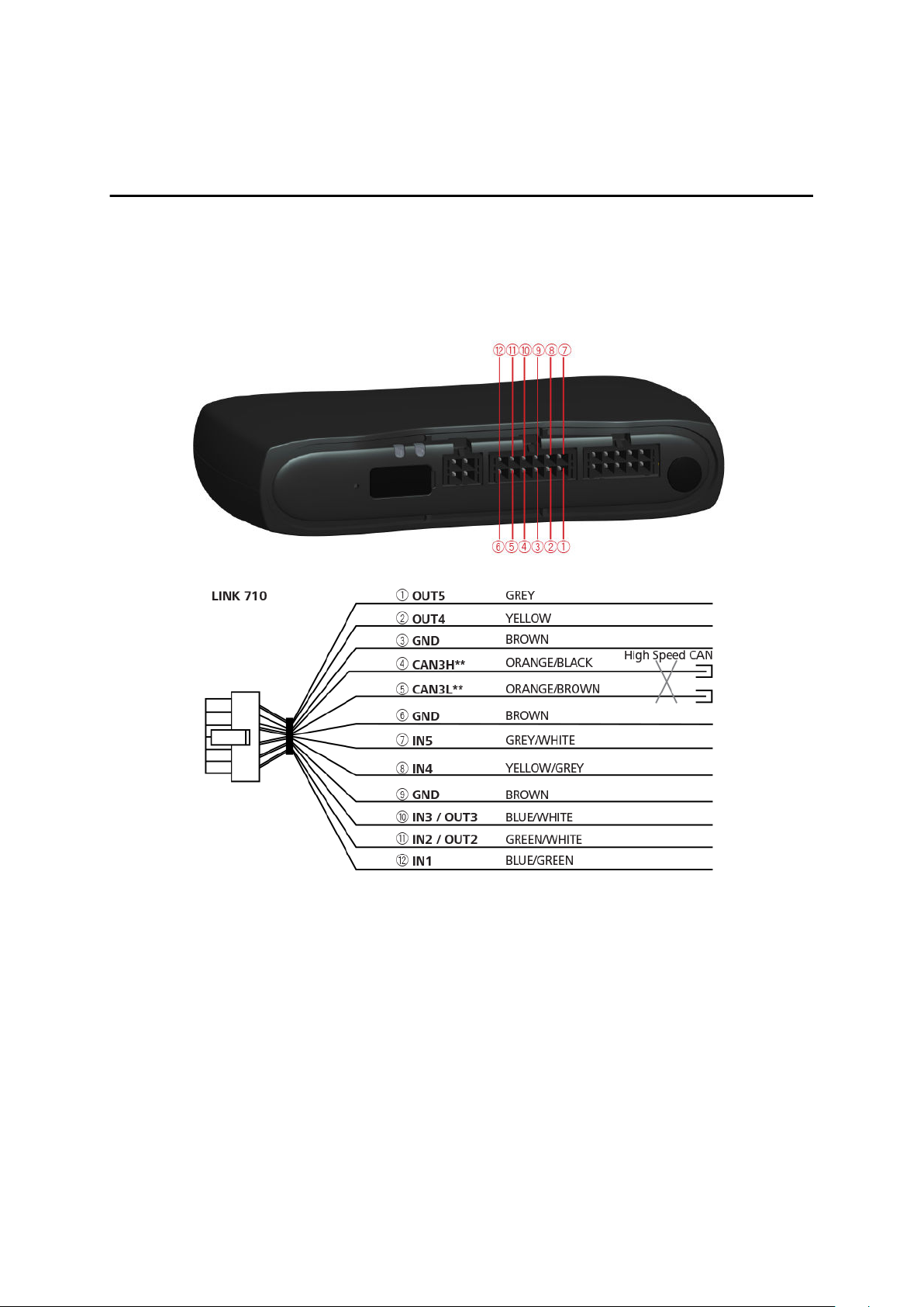
Appendix: Using the I/O connector
Using the 12 pin I/O cable, you can connect to a digital tachograph, as well as use
configurable digital inputs and outputs to connect accessories and 3rd-party devices.
For example, you can record inputs, for keeping a digital logbook with the help of a
switch, reporting times the vehicle is idling etc. You can connect the 12 pin I/O cable
from Webfleet Solutions to the 12 pin I/O cable connector of the LINK 710.
** Twisted pair. Loose ends of CAN L/CAN H wires must be protected against short
circuits. Separate by using a heat shrink tube.
Wiring digital inputs
The digital inputs of the LINK 710 operate according to the principle of a voltage
detector. Voltages below 2 Volts are definitively interpreted as being low and voltages
higher than 3 Volts are definitively interpreted as being high. The maximum
permissible input voltage is 30 Volts. Low/high switching (increasing input voltage)
typically occurs at 2.8 Volts. High/low switching (decreasing input voltage) typically
occurs at 2.1 Volts. The hysteresis of 0.7 Volts is to avoid rapid switching.
Interference voltages at the digital inputs must remain below 2 Volts. In order to
guarantee this, the input wire of the connecting cable should never remain
unconnected. If a digital input is not being used, the input wire must be connected to
ground (GND). To evaluate a switch, this switch needs to be designed as a change-
27
Page 28
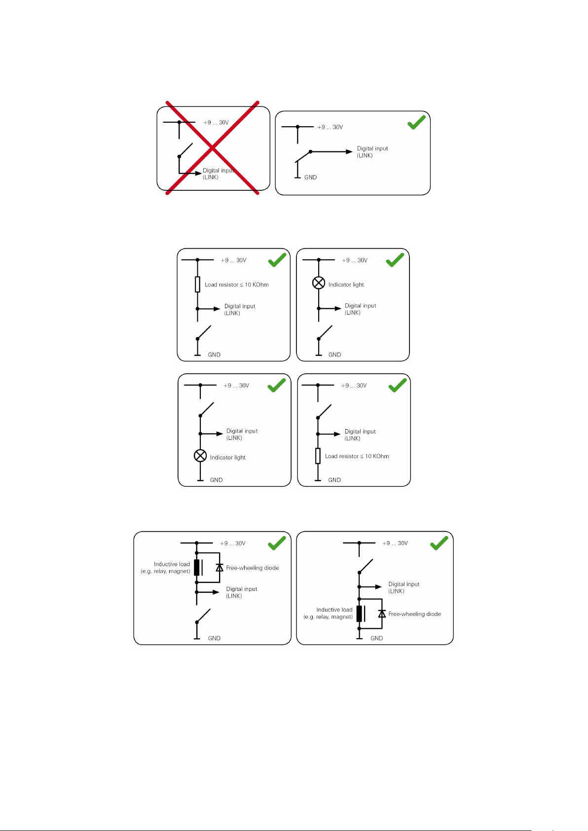
over switch, switching the digital input between plus and minus (ground GND) of the
vehicle electrical system voltage (+9 ... 30V).
If no change-over switch is available, an electric load for example, indicator light or
resistor, between the digital input and ground (GND) or between the digital input and
the vehicle voltage (+9 ... 30V) can offer defined levels.
When using inductive loads, a free-wheeling diode must be used in parallel with the
load.
Wiring the digital output
The digital output OUT of the LINK 710 is an open drain output linking to ground. The
connected load must be connected between vehicle voltage and OUT. Loads
requiring more than 0.35 A must be controlled with relays. If the load requires more
than the maximum output voltage use a 12 V/24 V relay, depending on the operating
voltage.
28
Page 29
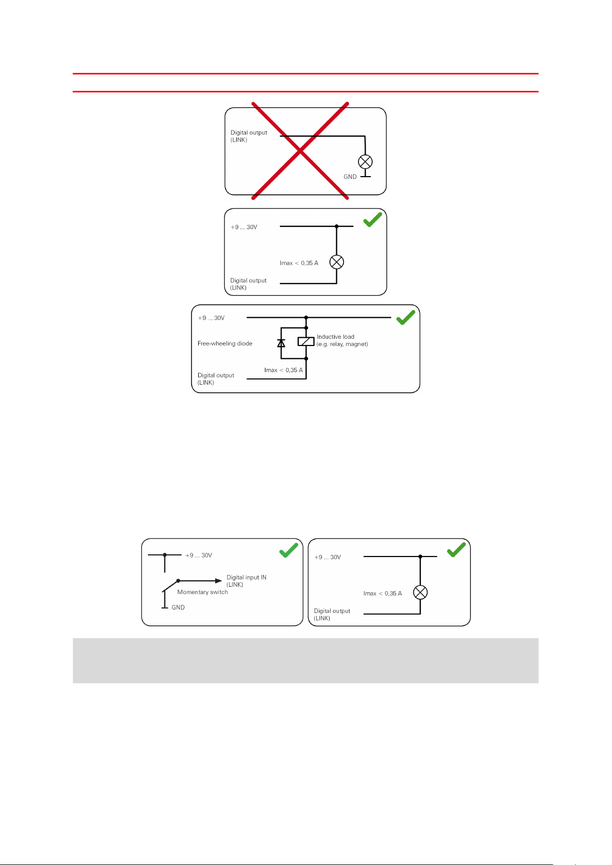
Caution: Do not switch safety relevant vehicle functions.
Using the IN and OUT for changing the logbook mode - 710
You can change the logbook mode using the IN/OUT of your LINK 710. Connect a
normally open momentary push button switch and an indicator light to the IN/OUT.
This requires configuration in WEBFLEET. You can use a normally open momentary
push button switch and a separate indicator light or a switch with an integrated
indicator light.
Connect a normally open momentary push button switch and indicator light to the
IN/OUT.
When you press the push button for a short time, the logbook mode switches to
Private trip. Then the indicator light will turn on. When you turn on the ignition the
logbook mode switches back to Business trip.
Using the input IN for changing the logbook mode
Your LINK 710 can report logbook-relevant information to WEBFLEET. Using the input
IN you can change the logbook mode between private and business trips. This
requires configuration in WEBFLEET.
29
Page 30

Connect a latched switch to IN as shown below.
If the switch is on (connected to vehicle voltage), the logbook mode is set to Private
trip. If the switch is off (connected to GND), the logbook mode is set to Business
trip.
Using the input IN for idle time reporting
Your LINK 710 can report idle times to WEBFLEET when the engine is running for
longer than five minutes and the vehicle is not moving. This requires configuration in
WEBFLEET.
The input IN must be connected to a signal indicating the activity of the engine, for
example alternator, engine, etc. The input IN must be active when the engine is
running.
30
Page 31

Addendum
Important Safety Notices and Warnings
Global Positioning System (GPS) and Global Navigation Satellite System (GLONASS)
The Global Positioning System (GPS) and Global Navigation Satellite System (GLONASS)
systems are satellite-based systems that provide location and timing information around the
globe. GPS is operated and controlled by the Government of the United States of America,
which is solely responsible for its availability and accuracy. GLONASS is operated and
controlled by the Government of Russia, which is solely responsible for its availability and
accuracy. Changes in GPS or GLONASS availability and accuracy, or in environmental
conditions, may impact the operation of this device. Webfleet Solutions disclaims any liability
for the availability and accuracy of GPS or GLONASS.
Safety messages
Important! Read before use!
Death or serious injury could result from failure or partial failure to follow these warnings and
instructions. Failure to properly set up, use, and care for this device can increase the risk of
serious injury or death, or damage to the device.
Use with care warning
It is your responsibility to use best judgment, due care and attention when using this device.
Don't allow interaction with this device to distract you while driving. Minimise the time spent
looking at the device screen while driving. You are responsible for observing laws that limit or
prohibit the use of mobile phones or other electronic devices, for example, the requirement to
use hands-free options for making calls when driving. Always obey applicable laws and road
signs, especially those relating to your vehicle’s dimensions, weight and payload type.
Webfleet Solutions does not guarantee the error-free operation of this device nor the accuracy
of route suggestions provided and shall not be liable for any penalties arising from your failure
to comply with applicable laws and regulations.
Proper mounting
Do not mount the device in a way that may obstruct your view of the road or your ability to
control the vehicle. Do not place the device in an area that may obstruct the deployment of an
airbag or of any other safety feature of your vehicle.
Pacemakers
Pacemaker manufacturers recommend that a minimum of 15cm / 6 inches be maintained
between a handheld wireless device and a pacemaker to avoid potential interference with the
pacemaker. These recommendations are consistent with independent research and
recommendations by Wireless Technology Research.
Guidelines for people with pacemakers:
You should ALWAYS keep the device more than 15cm / 6 inches from your pacemaker.
▪
You should not carry the device in a breast pocket.
▪
Other medical devices
Please consult your physician or the manufacturer of the medical device, to determine if the
operation of your wireless product may interfere with the medical device.
Device care
It is important to take care of your device:
▪
Do not open the casing of your device under any circumstances. Doing so may be
▪
dangerous and will invalidate the warranty.
31
Page 32

Prohibited uses
Aircraft and hospitals
Use of devices with an antenna is prohibited on most aircraft, in many hospitals and in many
other locations. This device must not be used in these environments.
CE mark and Radio Equipment Directive for LINK 710
This device can be used in all EU Member States. The frequency bands in which this
device operates are
▪ GSM: 900MHz, 1800 MHz,
▪ Bluetooth®: 2.4 GHz
and the maximum radio frequency emission power within these bands is:
▪ GSM: 2W, 33 dBm for 900MHz, 1W, 30 dBm for 1800 MHz,
▪ Bluetooth®: 2.5 mW, 4dBm.
Hereby, Webfleet Solutions declares that the radio equipment type telematics black
box is in compliance with Directive 2014/53/EU. The full text of the EU declaration of
conformity is available at the following internet address: https://www.webfleet.com/
webfleet/legal/doc/
EU Specific Absorption Rate (SAR) compliance
THIS WIRELESS DEVICE MODEL MEETS GOVERNMENT REQUIREMENTS FOR EXPOSURE TO
RADIO WAVES WHEN USED AS DIRECTED IN THIS SECTION
This GPS Navigation System is a radio transmitter and receiver. It is designed and manufactured
not to exceed the emission limits for exposure to radio frequency (RF) energy set by the
Council of the European Union.
The SAR limit recommended by The Council of the European Union is 2.0W/kg averaged over
10 grams of tissue for the body (4.0 W/kg averaged over 10 grams of tissue for the extremities hands, wrists, ankles and feet). Tests for SAR are conducted using standard operating positions
specified by the EU council with the device transmitting at its highest certified power level in all
tested frequency bands.
Button battery warning
This device contains a button battery. Button batteries can be dangerous and if swallowed
death or serious injury may occur. Seek immediate medical assistance if ingestion occurs.
Environmental and Battery information
Your device
Do not disassemble, crush, bend, deform, puncture, or shred your device. Do not use it in a
humid, wet and/or corrosive environment. Do not put, store or leave the device in a high
temperature location, in direct sunlight, in or near a heat source, in a microwave oven or in a
pressurised container, and do not expose it to temperatures over 70 °C (158 °F) or below -30
°C (-22 °F).
Long period storage: -40 °C to +80 °C / -40 °F to +176 °F
Avoid dropping the device. If the device is dropped and you suspect damage, please contact
customer support. Use the device only with the chargers, mounts or USB cables provided. For
Webfleet Solutions approved replacements, go to www.webfleet.com.
32
Page 33
Device battery (Non-replaceable)
This product contains a lithium ion battery.
Do not modify or re-manufacture the battery. Do not attempt to insert foreign objects into the
battery, or immerse or expose to water or other liquids. Do not expose the battery to fire,
explosion or other hazard.
Do not short circuit a battery or allow metallic conductive objects to contact battery terminals.
Do not attempt to replace the battery yourself unless the user manual clearly indicates that the
battery is user replaceable.
User replaceable batteries must only be used in systems for which they are specified.
Caution: Risk of explosion if the battery is replaced by an incorrect type.
Do not remove or attempt to remove the non-user-replaceable battery and contact a qualified
professional in case you wish to remove it.
Failure to follow these guidelines may cause the battery to leak acid, become hot, explode or
ignite and cause injury and/or damage. Do not attempt to pierce, open or disassemble the
battery. If the battery leaks and you come into contact with the leaked fluids, rinse thoroughly
with water and seek medical attention immediately.
Battery waste disposal
THE BATTERY CONTAINED IN THE PRODUCT MUST BE RECYCLED OR DISPOSED OF
PROPERLY ACCORDING TO THE LOCAL LAWS AND REGULATIONS AND ALWAYS KEPT
SEPARATE FROM HOUSEHOLD WASTE. BY DOING THIS YOU WILL HELP CONSERVE THE
ENVIRONMENT.
Operating temperature
This device will remain fully operational within the following temperature range:
LINK 710: -30 °C to +70 °C / -22 °F to +158 °F
Prolonged exposure to higher or lower temperatures can cause damage to your device and is
therefore advised against.
WEEE – e-waste disposal
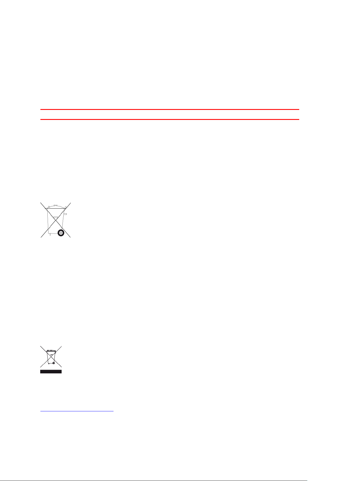
As required by Directive 2012/19/EU (WEEE) this product is marked with the crossed-out
wheeled-bin symbol on its body and/or packaging. This product shall not be treated as
household waste or be disposed of as unsorted municipal waste. To help protect the
environment, please dispose of this product by returning it to the point of sale or bringing it to
your local municipal collection point for recycling
How Webfleet Solutions uses your information
Information regarding the use of personal information can be found at:
www.webfleet.com/privacy.
33
Page 34

WEBFLEET
If your vehicle is configured to connect to WEBFLEET services, it will collect information for the
purposes of the WEBFLEET service while the vehicle is in use in association with other
WEBFLEET equipment installed in the vehicle.
The following information is continuously collected: vehicle location, g-force/acceleration data,
and engine-related data such as fuel consumption, valve positions, engine speed, and odometer
value. What information is collected specifically depends on the WEBFLEET equipment
installed in the vehicle.
The owner of the WEBFLEET contract decides what purposes this information is subsequently
used for, who will have access to it, and for how long the information is kept. Please refer to the
owner of the WEBFLEET contract for any additional information. This will usually be the owner
or lessee of the vehicle.
Exposure limits
This device complies with radiation exposure limits set forth for an uncontrolled environment.
In order to avoid the possibility of exceeding the radio frequency exposure limits, human
proximity to the antenna shall not be less than 20 cm (8 inches) during normal operation.
Limites d'exposition
Cet équipement est conforme aux limites d'exposition aux rayonnements définies pour un
environnement non contrôlé. Afin d'éviter tout dépassement potentiel des limites d'exposition
aux frèquences radio, tout être humain doit rester éloigné d'au moins 20cm (8 puces) de
l'antenne dans le cadre d'un fonctionnement normal.
Mobile networks
Devices that contain a mobile network module are intended for connection to one or more of
the following mobile network frequencies:
800/850/900/1800/1900/2100 MHz
Triman logo
Technical Specifications
Supply voltage
12 V / 24 V (min. 9 V to max. 30 V)
Maximum power consumption
14 V: 0.15 A / 2.1 W
28 V: 0.1 A / 2.8 W
Frequencies
Bluetooth®: 2400 MHz
GPS: 1575 MHz
GPRS/UMTS: 800/850/900/1800/1900/2100 MHz
34
Page 35

Model numbers
LINK 710: L0711
This document
Great care was taken in preparing this document. Constant product development may mean
that some information is not entirely up to date. The information is subject to change without
notice. Webfleet Solutions shall not be liable for technical or editorial errors or omissions
contained herein, nor for incidental or consequential damages resulting from the performance
or use of this document. This document may not be copied without the prior written consent
from Webfleet Solutions B.V.
WEBFLEET Telematics Service Platform
To use the LINK 710 you need a valid and active WEBFLEET Telematics Service
Platform subscription.
Accessories supplied with this device
▪ Power cable
▪ Holder
▪ Fixings
▪ Basic installation guide
Accessories not supplied with this device
To access all the features of your LINK 710 one or more of the following accessories
are required.
▪ PRO or TomTom PRO Driver Terminal
▪ LINK 105
▪ External GPS antenna (if the installation location does not grant enough GPS
reception quality)
▪ LINK CAN Sensor 100
▪ On/Off Privacy Switch (red)
▪ Privacy Button (green, 12V)
Note: Alternative fixed installation docks are available
Terms and conditions: Limited warranty and EULA reference
Our terms and conditions, including our limited warranty and end user license terms apply to
this product; visit https://www.webfleet.com/legal
35
Page 36

Copyright notices
© 2019 Webfleet Solutions. All rights reserved. WEBFLEET is a registered trademark of
Webfleet Solutions B.V. or one of its Affiliates.
Bluetooth®
The Bluetooth® word mark and logos are registered trademarks owned by Bluetooth SIG, Inc.
and any use of such marks by Webfleet Solutions is under licence. Other trademarks and trade
names are those of their respective owners.
Copyright (c) 2018 - Tcl/Tk - Regents of the University of California, Sun Microsystems, Inc., Scriptics Corporation, and other parties
https://www.tcl.tk/
This software is copyrighted by the Regents of the University of California, Sun Microsystems,
Inc., Scriptics Corporation, and other parties. The following terms apply to all files associated
with the software unless explicitly disclaimed in individual files.
The authors hereby grant permission to use, copy, modify, distribute, and license this software
and its documentation for any purpose, provided that existing copyright notices are retained in
all copies and that this notice is included verbatim in any distributions. No written agreement,
license, or royalty fee is required for any of the authorized uses. Modifications to this software
may be copyrighted by their authors and need not follow the licensing terms described here,
provided that the new terms are clearly indicated on the first page of each file where they
apply.
IN NO EVENT SHALL THE AUTHORS OR DISTRIBUTORS BE LIABLE TO ANY PARTY FOR
DIRECT, INDIRECT, SPECIAL, INCIDENTAL, OR CONSEQUENTIAL DAMAGES ARISING OUT OF
THE USE OF THIS SOFTWARE, ITS DOCUMENTATION, OR ANY DERIVATIVES THEREOF, EVEN
IF THE AUTHORS HAVE BEEN ADVISED OF THE POSSIBILITY OF SUCH DAMAGE.
THE AUTHORS AND DISTRIBUTORS SPECIFICALLY DISCLAIM ANY WARRANTIES, INCLUDING,
BUT NOT LIMITED TO, THE IMPLIED WARRANTIES OF MERCHANTABILITY, FITNESS FOR A
PARTICULAR PURPOSE, AND NON-INFRINGEMENT. THIS SOFTWARE IS PROVIDED ON AN
"AS IS" BASIS, AND THE AUTHORS AND DISTRIBUTORS HAVE NO OBLIGATION TO PROVIDE
MAINTENANCE, SUPPORT, UPDATES, ENHANCEMENTS, OR MODIFICATIONS.
GOVERNMENT USE: If you are acquiring this software on behalf of the U.S. government, the
Government shall have only "Restricted Rights" in the software and related documentation as
defined in the Federal Acquisition Regulations (FARs) in Clause 52.227.19 (c) (2). If you are
acquiring the software on behalf of the Department of Defense, the software shall be classified
as "Commercial Computer Software" and the Government shall have only "Restricted Rights" as
defined in Clause 252.227-7013 (c) (1) of DFARs. Notwithstanding the foregoing, the authors
grant the U.S. Government and others acting in its behalf permission to use and distribute the
software in accordance with the terms specified in this license.
36
Page 37

Webfleet Solutions Limited Warranty
WARRANTOR
Non-U.S. and non-Canadian purchases: If you have made your purchase outside the United
States and Canada, this Limited Warranty is granted by and this Limitation of Liability is
stipulated for the benefit of Webfleet Solutions B.V., De Ruijterkade 154, 1011 AC Amsterdam,
The Netherlands.
WHAT THIS WARRANTY COVERS
1 Webfleet Solutions B.V. (“Webfleet Solutions”) warrants to you that the Hardware will be free
from defects in workmanship and materials under normal use (“Defects”) for a period of one (1)
year from the date that the Hardware was first purchased by you (“Warranty Period”). During
the Warranty Period the Hardware will be repaired or replaced at Webfleet Solutions’ choice
(“Limited Warranty”) without charge to you for either parts or labour. This Limited Warranty
covers the replacement of the Hardware only. If the Hardware is repaired after the Warranty
Period has expired, the Warranty Period for the repair will expire six (6) months after the date
of repair.
WHAT THIS WARRANTY DOES NOT COVER
2 The Limited Warranty does not apply to normal wear and tear, does not apply when the
Hardware is opened or repaired by someone not authorized by Webfleet Solutions and does
not cover repair or replacement of any Hardware or part thereof damaged by: misuse, moisture,
liquids, proximity or exposure to heat and accident, abuse, non-compliance with the
instructions supplied with the Hardware, neglect or misapplication. The Limited Warranty does
not cover physical damage to the surface of the Hardware. This Limited Warranty does not
cover any software that may accompany or be installed on the Hardware. The Limited Warranty
does not cover the installation, removal or maintenance of the Hardware or any costs related
herewith.
HOW TO MAKE A WARRANTY CLAIM
3 In order to make a claim of a Defect, you must contact Webfleet Solutions during the
Warranty Period via www.webfleet.com to explain the Defect and to obtain an RMA number
(Return Materials Authorization) if necessary. You must return the Hardware during the
Warranty Period, along with the RMA number provided by Webfleet Solutions and an
explanation of the Defect, to the address provided to you by Webfleet Solutions. If a defect
arises and a valid claim under this Limited Warranty is received by Webfleet Solutions after the
first one hundred and eighty (180) days of the Warranty Period, Webfleet Solutions is entitled
to charge you for any reasonable shipping and handling costs made in connection with the
repair or replacement of the Hardware. You must comply with any other return procedures
stipulated by Webfleet Solutions, if any.
YOUR LEGAL RIGHTS
4 Some countries may not allow the exclusion or limitation of damages. If any part of this
Limited Warranty is held to be invalid or unenforceable, the remainder of the Limited Warranty
shall nonetheless remain in full force and effect.
5 This Limited Warranty is the only express warranty made to you and is provided in lieu of any
other express warranties or similar obligations (if any) created by any advertising,
documentation, packaging, or other communications.
6 Except for the Limited Warranty and to the maximum extent permitted by applicable law,
Webfleet Solutions and its suppliers provide the Hardware “AS IS AND WITH ALL FAULTS”, and
hereby disclaim all other warranties and conditions, whether express, implied or statutory,
including, but not limited to, any (if any) implied warranties, duties or conditions of satisfactory
quality, of fitness for a particular purpose, of reliability or availability, of accuracy or
completeness of responses, of results, of workmanlike effort, of lack of viruses, and of
reasonable care and skill, all with regard to the Hardware, and the provision of or failure to
provide support or other services, information, software, and related content through the
37
Page 38

Hardware or otherwise arising out of the use of the Hardware. Also, there is no warranty or
condition of quiet enjoyment, quiet possession, or non-infringement with regard to the
Hardware. This exclusion does not apply to
(I) any implied condition as to title and
(II) any implied warranty as to conformity with description.
7 This Limited Warranty does not affect any legal rights under applicable national legislation
governing the sale of consumer goods.
8 This Limited Warranty cannot be transferred to any other person.
LIMITATION OF LIABILITY
9 Neither Webfleet Solutions nor its suppliers shall be liable to you or to any third party for any
damages either direct, indirect, incidental, consequential or otherwise (including in each case,
but not limited to, damages for the inability to use the equipment or access data, loss of data,
loss of business, loss of profits, business interruption or the like) arising out of the use of or
inability to use the Hardware even if Webfleet Solutions has been advised of the possibility of
such damages.
10 Notwithstanding any damages that you might incur for any reason whatsoever (including,
without limitation, all damages referenced herein and all direct or general damages in contract
or anything else), the entire liability of Webfleet Solutions and any of its suppliers shall be
limited to the amount actually paid by you for the Hardware.
11 Webfleet Solutions shall not be liable for
(I) any fraud on the part of its employees and/or agents; or
(II) any fraudulent misrepresentation on the part of its employees and/or agents.
12 Notwithstanding the above, neither party’s liability for death or personal injury resulting from
its own negligence shall be limited.
38
 Loading...