

Page 1
Note - Figures in these instructions are intended to
represent all Genesis Gas Barbecue models, your
barbecue may differ from these illustrations.
Your Weber
®
Genesis®Gas Barbecue, as well as any
outdoor gas appliance, is a target for spiders and other
insects. They can nest in the venturi section of the
burner tubes. This blocks the normal gas flow, and can
cause the gas to flow back out of the air shutter.
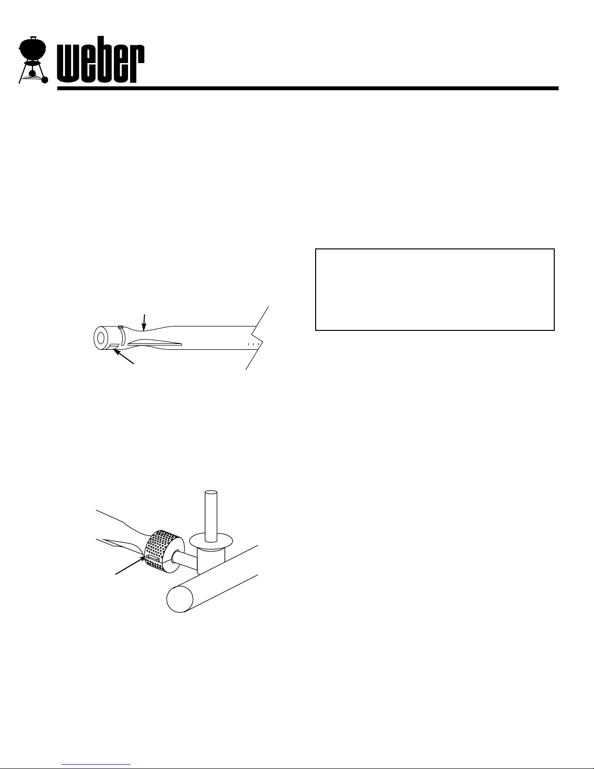
Figure 1. This could result in a fire in and around the air
shutters, under the control panel, causing serious
damage to your barbecue. We have developed the
Weber Spider Stopper Guards to significantly
reduce the chance of this happening to your Weber
Genesis Gas Barbecue.
The Weber Spider Stopper Guard fits tightly around the
air shutter section of the burner tube and the valve,
thereby preventing spiders and other insects access to
the burner tubes through the air shutter openings.
Figure 2.
Figure 2
Weber Spider
Stopper Guard
Figure 1
Air shutter
Venturi
®
®
Weber®Spider Stopper™Guards
Installation Instructions
We recommend that you inspect the Weber Spider
Stopper Guards at least once a year. Also inspect and
clean the Spider Stopper Guards if any of the
following symptoms should ever occur.
1. The smell of gas in conjunction with the burner
flames appearing yellow and lazy.
2. Barbecue does not reach temperature.
3. Barbecue heats unevenly.
4. One or more of the burners do not ignite.
WARNING: Make sure gas supply is turned off; i.e.:
LP cylinder valve is closed or natural gas supply
shut-off turned off and hose disconnected from the
Quick Disconnect.
Note - You should inspect the burners for spider webs
and other obstructions before installing your new
Weber Spider Stopper Guards. To inspect the burners,
you must remove the manifold. The following
instructions show you how to both remove the manifold
and install the Weber Spider Stopper Guards.
Step 1
For LP units only, disconnect the gas hose from the LP
tank.
Step 2
Pull off all burner control knobs. Remove control panel.
Step 3
Remove the igniter.
DANGER
Failure to correct these symptoms may
result in a fire which can cause serious
bodily injury or death, and cause damage
to property.
For Genesis 1, 2, 3, 4, 5 and Perma-Mount Gas Barbecues
27-39900 Rev. 3/90
Page 2
Step 4
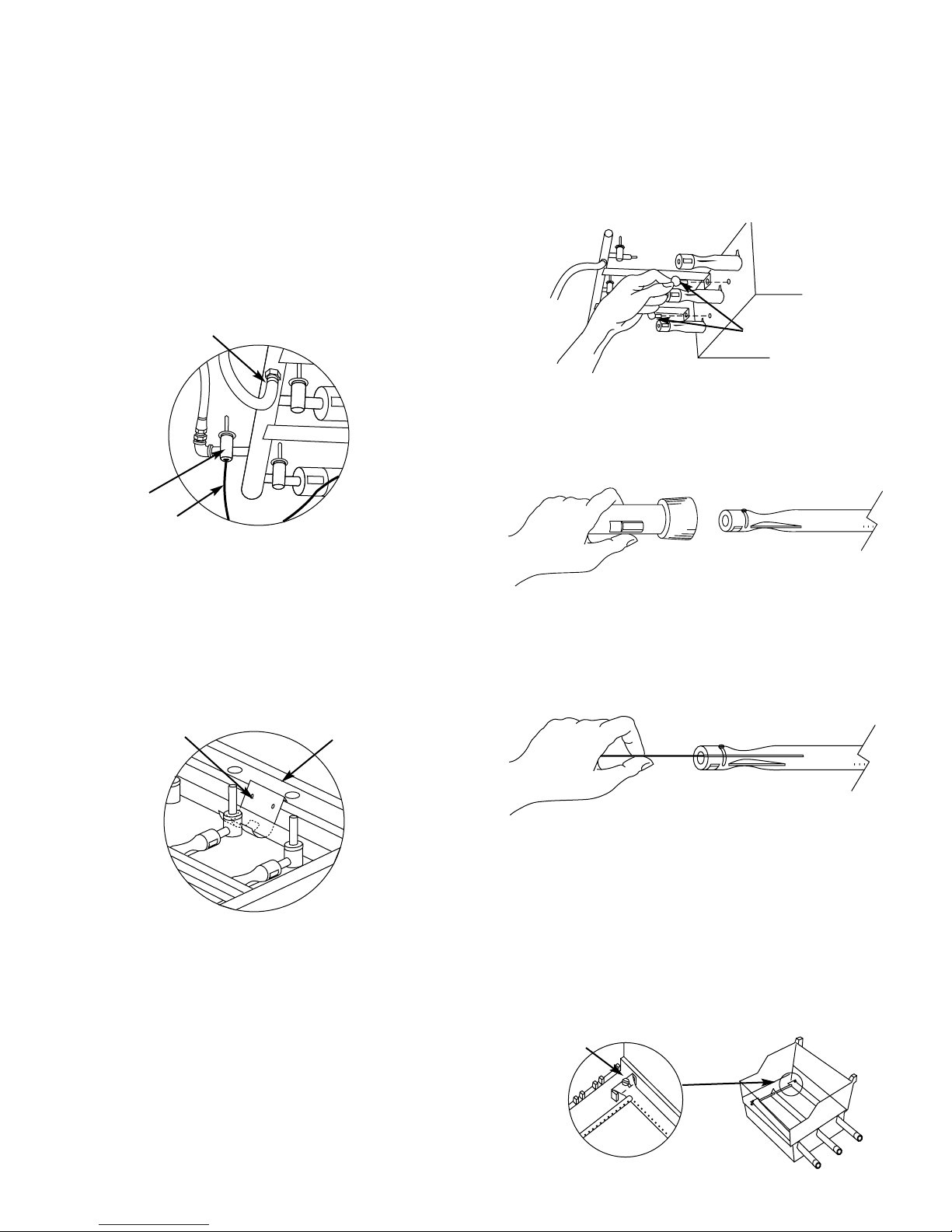
• On Genesis 4, 5 and Perma-Mount Gas Barbecue
models with a FlameCheck Safety System you must
disconnect the capillary tube from the FlameCheck
valve. Figure 3.
Note - The end of the capillary tube and the bottom of
the FlameCheck valve must be kept free of dirt and oil
(even oil from your fingers). Be careful when
disconnecting the capillary tube.
• On units with a side burner, disconnect the side
burner hose from the side burner fitting on the manifold
and remove the side burner. Figure 3.
Step 5
Remove the manifold bracket: Place your hand
underneath the bracket. Lift the bracket, manifold and
cooking box as a unit and unhook the bracket from the
frame brace. Figure 4. Remove the bracket from the
manifold.
Note - Your Weber Genesis Gas Barbecue may not
have a manifold bracket. Manifold brackets may be
obtained from:
Weber-Stephen Products Co.
Customer Service Center
560 S. Hicks Rd.
Palatine, IL 60067-6971
(708) 705-8660
(800) 446-1071
Side burner fitting
FlameCheck
valve
Capillary
tube
Figure 3
Manifold bracket
Frame brace
Figure 4
Step 6
Remove the manifold
Unscrew the thumb screws that hold the manifold to the
cooking box, and pull the manifold out of the burners and
set it down carefully. Figure 5.
Note - It may be necessary to use a pair of pliers to
loosen the thumb screws.
Step 7
Using a flashlight, look inside each burner for any
obstructions. Figure 6.
Step 8
Use the burner cleaning tool or a straight piece of wire to
clean the burner tubes of any obstructions, if necessary.
Figure 7.
Step 9
Install the Manifold
Insert the valves into the ends of the burner tubes and
install the manifold thumb screws; hand tighten. If you
have trouble installing the manifold, check the burner tube
alignment: Remove the cooking grills and Flavorizer Bars
and make sure the slots on the burner tubes are installed
under the heads of the guide screws. These screws
should not be fully tightened. Figure 8.
View from below
and behind
cooking box
Thumb screws
Figure 5
Figure 6
Figure 7
Guide screw
Figure 8
2
Page 3

Step 10
Install the Manifold Bracket
Hook the bracket onto the manifold at the center burner
valve. Refer to page 2, Step 5, Figure 4. Place your
hand underneath the bracket, slightly lift the bracket,
manifold and cooking box as a unit, and hook the
bracket onto the frame brace.
Step 11
Check air shutter openings
The air shutters should be open approximately 1/8 to
3/16 of an inch Figure 9.
Step 12
• On units with a side burner, install the side burner
and reconnect the side burner hose to the side burner
fitting on the manifold.
• On Genesis 4, 5 and Perma-Mount Gas Barbecue
models with a FlameCheck Safety System you must
reconnect the capillary tube to the FlameCheck valve.
Do not over-tighten.
Step 13
Reinstall the igniter.
Step 14
Install Spider Stopper Guards
Fit the Spider Stopper Guards around the burner tube
and the valve. The large hole fits around the burner and
the small hole fits around the valve. Latch the guard.
Figure 10.
Turn screw
to loosen
Air shutter
Figure 9
Figure 10
Step 15
Check the fit of the Spider Stopper Guards
Slightly rotate the Spider Stopper Guards, if necessary,
so that the seams are in line with the Venturi fins. There
should be no gaps in the seams or in the fit around the
burners and valves. Figure 11.
Step 16
Check for gas leaks at all connections
Refer to your Owner’s Manual.
WARNING: You should check for gas leaks every
time you disconnect and reconnect any gas fitting.
Step 17
Install burner control knobs and control panel.
Inspection and cleaning of the Weber Spider
Stopper Guards
To inspect the Spider Stopper Guards, remove the control
panel, and look to see if they have dust or dirt on their
outside surfaces. If dust or dirt has accumulated, brush it
off with a soft bristle brush (for example, an old toothbrush). Check that there are no gaps in the Spider
Stopper Guards’ seams or in the fit around the burners or
valves. See Figure 11.
Check fit
around valve
Check fit
around burner
Venturi fin
Venturi fin
Figure 11
DANGER
Do not use an open flame to check for
gas leaks. Be sure there are no sparks or
open flames in the area while you check
for leaks. This may result in a fire or
explosion which can cause serious bodily
injury or death and damage to property.
3
 Loading...