

Page 1
LP
US ENGLISH
15
14
16
13
12
17
11
55980 US 02/28/07
310, 320
21
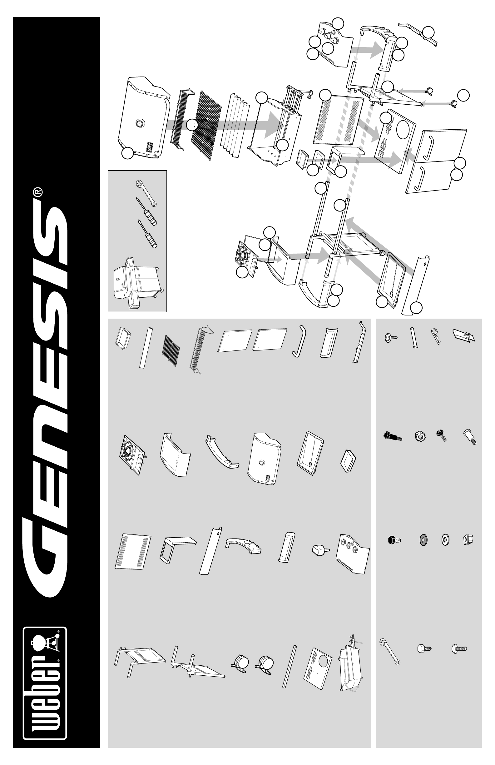
TOOLS NEEDED:
HerramientaERRAMIENTAS REQUERIDAS:
OUTILS NECESSAIRES:
18
6
14
15
23
4
1
3
7
9
20
5
8
2
2
- 5
- 5
®
®
Bar - 5
®
Bandeja de goteo desechable - 2
Egouttoir jetable - 2
Disposable Drip Pan - 2
Barra Flavorizer
Barre Flavorizer
Flavorizer
Cooking Grate - 2
Parrilla de cocción - 2
Grille de cuisson - 2
Rejilla para calentar - 1
Grille de maintien au
Warming Rack - 1
chaud - 1
Left Door Panel - 1
22
Panel de la puerta derecha - 1
Panneau de porte gauche - 1
Panel de la puerta izquierda - 1
Right Door Panel - 1
Panneau de porte droit - 1
Asa de la puerta - 2
Poignée de porte - 2
Door Handle - 2
Left Front Trim Assembly - 1
12
11
Mensula de soporte del
múltiple - 1
Support pour le support
Manifold Support Bracket - 1
Garniture avant gauche
Ensemble - 1
Moldura izquierda delantera
Ensamble - 1
du collecteur - 1
19
Tornillo - 5
Vis - 5
Screw - 5
10
Pasador de horquilla - 2
Clevis Pin - 2
Axe - 2
Cotter Pin - 2
Clavija hendida - 2
Goupille fendue - 2
Herramientas de ferreteria para la
bandeja recolectora de grasa - 6
Boulonnerie de Plateau inférieur - 6
Bottom Tray Hardware - 6
ASSEMBLY INSTRUCTIONS • INSTRUCCIONES DE MONTAJE • INSTRUCTIONS DE MONTAGE
Quemador lateral - 1
Brûleur latéral - 1
Side Burner - 1
Panel trasero - 1
Rear Panel - 1
Panneau arrière - 1
Mesa lateral
izquierda - 1
Left Side Table - 1
Tablette latérale
gauche - 1
Sostenedor del plato
recolector - 1
Catch-Pan Holder - 1
Support de l’égouttoir - 1
Ensamble de la moldura
izquierda - 1
Left Trim Assembly - 1
Panel delantero - 1
Panneau avant - 1
Front Panel - 1
Structure - 1
Defensa - 1
Ensemble de garniture
gauche - 1
Ensamble de la moldura derecha - 1
Right Trim Assembly - 1
Shroud - 1
Moldura derecha delantera
Ensemble de garniture droit - 1
Right Front Trim Assembly - 1
Bandeja de goteo - 1
Drip Tray - 1
Ensamble - 1
Garniture avant droite
Ensemble - 1
Plato recolector - 1
Egouttoir - 1
Plateau de recueil des
gouttes - 1
Perilla - 3
Knob - 3
Catch-Pan - 1
Bouton - 3
Mesa lateral derecha - 1
Right Side Table - 1
Perno de 2 1/4 pulgadas (1/4 x 20 x
2 1/4 pulg.) - 2
2 1/4 Inch Bolt (1/4 x 20 x 2 1/4 In.) - 2
Cinc negro 1/2 pulgada Pernos hex-
1/2 Inch Black Zinc Hex Bolts
Tablette latérale droite - 1
(1/4 x 20 x 1/2 In.) - 8
Boulon de 2 1/4 pouces (1/4 x 20 x
agonales (1/4 x 20 x 1/2 pulg.) - 8
Tuerca de enclavamiento - 2
2 1/4 po.) - 2
Ecrous hexagonaux en zinc noir de
Écrou Keps - 2
Keps Nut - 2
Nylon Washer - 20
1/2 pouce (1/4 x 20 x 1/2 po.) - 8
Tornillo de máquina #8 - 32 - 4
Vis de mécanique de #8 - 32 - 4
#8 - 32 Machine Screw - 4
Arandela de nilón - 20
Arandela de aluminio - 6
Rondelle en nylon - 20
Rondelle en aluminium - 6
Aluminium Washer - 6
Perno de tope (1/4 x 20 x 1 pulg.) - 4
Vis à boulon de la structure (1/4 x
20 x 1 po.) - 4
Shoulder Bolt Screw (1/4 x 20 x 1 In.) - 4
Tapón plástico - 2
Bouchon en plastique - 2
Plastic Plug - 2
Bastidor izquierdo - 1
Coffrage gauche - 1
Left Frame - 1
Bastidor derecho - 1
Coffrage droit - 1
Right Frame - 1
Rueda loca con traba - 2
Locking Caster - 2
Rueda loca - 2
Ecrou de verrouillage - 2
Ecrou - 2
Caster - 2
Soporte del bastidor - 2
Support de coffrage - 2
Frame Support - 2
Bandeja del fondo - 1
Bottom Tray - 1
Ensamble de la caja de
Plateau inférieur - 1
Cookbox Assembly - 1
cocción - 1
Ensemble du boîtier de
cuisson - 1
11 mm (7/16 in.) Wrench - 1
Llave de 11 mm (7/16 pulg.) - 1
Clé de 11 mm (7/16 po.) - 1
Acero inoxidable 1/2 pulgada Pernos
1/2 Inch Stainless Steel Hex Bolts
(1/4 x 20 x 1/2 In.) - 12
hexagonales (1/4 x 20 x 1/2 pulg.) - 12
Ecrous hexagonaux en acier inoxydable
de 1/2 pouce (1/4 x 20 x 1/2 po.) - 12
Ecrous en zinc de 1 pouce (1/4 x 20
1 Inch Zinc Bolts (1/4 x 20 x 1 In.) - 4
x 1 po.) - 4
Cinc 1 pulgada Pernos (1/4 x 20
x 1 pulg.) - 4
Page 2
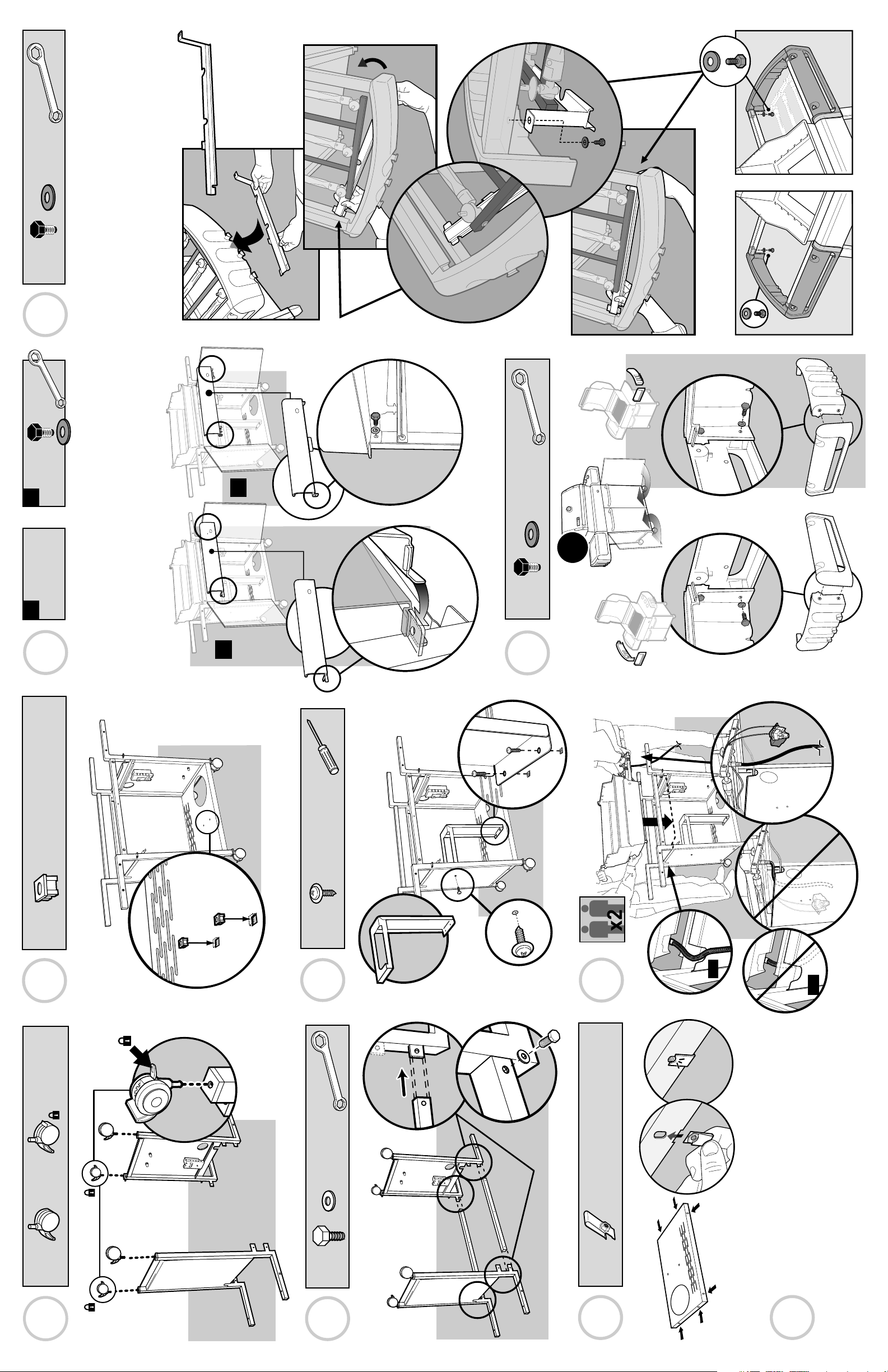
1.
2.
1 -
13
2 -
Nota: Si esta pieza no vino con su barbacoa
salte al Paso 14.
Remarque : Si cette pièce n’est pas fournie avec
Note: If this part did not come with your grill
skip to Step 14.
votre grill, passez à l’Etape 14.
b.
b.
b.
1
a. b.
10
• Identifi que el estilo del panel delantero (A o B) y luego siga las
• Identify Front Panel style (A or B) then follow illustration (A or B).
l’illustration (A ou B).
instrucciones de la ilustración correspondiente (A o B).
• Identifi ez le style du Panneau avant (A ou B) puis suivez
a.
4 -
11
a.
a.
2 -
5A
2 -
3 -
5B
• aluminium
• aluminio
• aluminium
6
320
320
2 -
1
4 -
2
6 -
3A
the ground.
• Flip over frame assembly so the casters are on
ruedas locas estén sobre el piso.
• Voltee el ensamble del bastidor de manera que las
que les écrous se trouvent sur le sol.
• Retournez l’ensemble du coffrage de façon à ce
3B
Page 3

14
2.
3 -
6 - 2 -4 -
12
• aluminium
• aluminio
• aluminium
1.
2.
2 -
7
2 -
4 -
8
9
1.
• To adjust door:
• Para ajustar la puerta:
• Pour ajuster la porte:
4 -
3C
4 -
4
Page 4

1.
2.
4.
5.
3.
b
.
1
O
F
F
A
R
R
E
T
E
/
A
P
A
G
A
D
O
1
O
F
F
A
R
R
E
T
E
/
A
P
A
G
A
D
O
6.
a
.
50451 12/01/06
CAUTION: TURN THE GAS OFF AT THE
GAS SUPPLY, BEFORE STARTING
.
KNOB BEZEL
ADJUSTMENT INSTRUCTIONS
TOOLS
NEEDED:
1. LoosenScrews.
2. Makesurebezel movesfreely
inalldirections.
3. Matchendof alignmenttoolwithvalve stembylooking downbarreloftool (a).
Pushalignmenttool ontovalvestem (b).
Whileholdingcontrol knob bezel, gently push alignment tool down.
Toolmustfreely return to up position.
4. Oncealigned,continue to
holdcontrolknob bezel
andtightenscrews. Push
toolagainto check for
freemovement.
5. Removealignmenttool.
6. Installknobonto valvestem
andtestfor free movement.
Readjustif
necessary.
AlignmentTool PhillipsScrewdriver
KnobBezel
a)
b)
16
15
2 -
18
See sheet in control knob packaging for bezel adjust-
pour les instructions de réglage de la collerette.
las molduras decorativas.
ajustarse ahora.
Refi érase a la hoja dentro del empaque de la perilla
de control para las instrucciones sobre como ajustar
IMPORTANT:
La collerette du bouton doit être ajustée à ce stade.
Voir la fi che fournie avec le bouton de commande
ment instructions.
IMPORTANTE:
Las molduras decorativas de la perilla deben
1
.
1
.
,
B
L
o
E
o
FO
s
e
n
RE
S
c
r
e
w
s
.
IMPORTANT:
Knob bezels must be adjusted at this point.
H
E
S
G
T
A
A
R
S OFF
TIN
G
.
A
T
T
H
E
17
LY
:
TUR
N
T
3 -
• Refer to Owner’s Manual for clip installation warning.
• Refi érase al Manual del Propietario para la advertencia referente a la instalación
• Veuillez consulter le Manuel du Propriétaire pour l’installation de la pince.
de la presilla.
23
21
2 -
20
19
22
4 -
320
 Loading...