

Page 1

Webasto AG, Global Comfort Solutions © 2007 All Rights Reserved
Air Conditioning Installation and
Operating Instructions
Blue Cool Premium
Ident.-Nr.: 0903071A
Page 2

D
I
G
I
T
A
L
C
O
N
T
R
O
L
P
A
N
E
L
EDITION DATED 21ST AUGUST 2006
CHILLER SYSTEMS - OPERATION AND INSTALLATION MANUAL - PAGE : 1
Webasto AG - Special Products & Markets
Kraillinger Strasse 5, 82131 STOCKDORF, Germany
Tel. : +49(0) 89 8 57 94 543 Fax : +49(0) 89 8 57 94 753 Website : www.webasto.de
F
U
N
C
T
I
O
N
I
N
G
P
R
I
N
C
I
P
L
E
S
Webasto - Marine Air Conditioning
OVER-BOARD DISCHARGE
CHILLER UNIT
COOL CYCLE LED
COMPRESSOR RUN LED
SET-POINT MODIFICATION
KEYS
BLOWER KEY
AUTO CYCLE SWITCHING LED
HEAT CYCLE LED
MAIN ON/OFF SWITCH
FUNCTION KEY / SECONDARY COMMANDS
CHILLED WATER AIR-CONDITIONING SYSTEMS
OPERATING AND INSTALLATION MANUAL
DIGITAL CABIN
CONTROL PANEL
FLEXIBLE AIR-DUCT
2ND AIR-HANDLER - VERTICAL
SLIM-LINE MODEL
TRANSITION BOX +
SUPPLY AIR-GRILLE
RETURN AIR GRILLE
Tee JUNCTION
TO 2ND AIRHANDLER
TUBULAR INSULATION
AROUND CHILLED
WATER CIRCUIT
PIPING
CHILLER UNIT
ELECTRICAL CONTROL BOX
SEA-WATER PUMP
AIR-HANDLER COMPACT SERIES
CIRCULATION PUMP
CHILLER UNIT
DIGITAL CONTROL
PANEL
NEW ELECTRONICS - 2004 SERIES
ROOM TEMPERATURE OR
SET-POINT TEMPERATURE
OR SECONDARY FUNCTION READ-OUT
Page 3

2004 SERIES - CHILLER SYSTEMS - OPERATION AND INSTALLATION MANUAL - PAGE : 2
2004 SERIES - CHILLER SYSTEMS - OPERATION AND INSTALLATION MANUAL - PAGE : 2
EDITION DATED 21ST AUGUST 2006
CHILLED WATER AIR-CONDITIONING SYSTEMS
OPERATING AND INSTALLATION MANUAL
CONTENTS
Page
1) General information ...................................................................................................
2) Digital Display <CHILLER CONTROL> ..................................................................
2.1 - Drawing Digital Display - Operation Guide........................................................
3) Central Blower Control ...............................................................................................
4) Visual Error Codes Digital Display ............................................................................
5) Cabin Blower Control .................................................................................................
5.1 - Wiring diagram - <CAB> 230V AC Cabin Control ..........................................
6) Programmable Functions Chiller Condensing Units ..................................................
6.1 - Digital Display - Programming access ...............................................................
7) Pratical Installation of Components - Guidelines .......................................................
7.1 - Installation Drawing - Sea Water Pump system .................................................
8) Chilled Water Circuit Installation ................................................................................
8.1 - Integration of Added Heat-Exchangers in Chilled Water Circuit .......................
Golden Rules - Chilled Water Piping Installation .......................................................
Filling and Purging of a Chilled Water Circuit ...........................................................
Examples of Chilled Water Circuit Piping Schematics ..............................................
8.6 - Example Chilled Water Circuit Piping - Small 20000 BTU Chiller ..................
8.7- Example Chilled Water Piping - WBCP24/D Stern Location - 4 Air-Handlers .
8.8 - Example - Catamaran - WBCP36/D - Central Location - 6 Air-Handlers .........
8.9 - Example - Motoryacht - WBCP72/D Twin - Aft location - 10 Air-handlers .....
8F - Air Ducts - Ventilation ..............................................................................................
9) Routine Checks/Trouble Shooting...............................................................................
11) Wiring diagrams .........................................................................................................
11.1 - Wiring diagram single compressor WBCP12/16/20/24/30 - 1 phase................
11.2 - Wiring diagram single/twin compressor - 1/3 phase .......................................
11.3 - Wiring diagram compressor 3/4 - single and 3 phase .....................................
11.4 - Power Supply Schematics - TWIN/CI Chillers - single phase 230V ..............
11.5 - Power Supply Schematics - TWIN/TRI (3) compr. Chillers - 1 phase 230V .
11.6 - Power Supply Schematics - TWIN/TRI (3) compr. Chillers - 3 phase 400V .
11.7 - Wiring Diagram automatic staging secondary AC loads ..................................
11.8 - Wiring Diagram - Running Capacitors - ECOFIT Blowers ............................
11.9 -
Wiring Diagram - Connection 3-Way valve (Lizhan/Zhongli) on TECC card
Webasto AG - Special Products & Markets
Kraillinger Strasse 5, 82131 STOCKDORF, Germany
Tel. : +49(0) 89 8 57 94 543 Fax : +49(0) 89 8 57 94 753 Website : www.webasto.de
3
3
3
4
4
6
7
9
9
11
11
12
12
13
14
15
15
15
16
17
18
19
20
21
22
23
24
24
25
26
26
26
Page 4

2004 SERIES - CHILLER SYSTEMS - OPERATION AND INSTALLATION MANUAL - PAGE : 3
2004 SERIES - CHILLER SYSTEMS - OPERATION AND INSTALLATION MANUAL - PAGE : 3
As from May 2004 all WEBASTO air conditioning units are controlled by a Digital
Display <CHILLER CONTROL> 2004
SERIES which gives access to all functions
necessary for the normal operation of the unit
and attached accessories (blowers, pumps,
etc).
All WEBASTO air conditioning units are
sea-water cooled by means of an AC seawater pump.
In order to start the system you only need to
press the On/Off key on the digital display.
From there on the electronic control unit
takes care of the progressive starting up of
the air conditioning components as well as it
normal functioning.
The digital display will show the present
room temperature of the cabin in which the
digital display is situated or where the main
temperature sensor is located (in case the
optional secondary temperature sensor is
used).
The WEBASTO <CHILLER CONTROL>
digital display allows access to information
and controls at three distinct levels :
Immediate Access - Level 1 :
1) Room temperature read-out in the main 4
LED display window
2) 3 small LED’s to the left indicating the
operating cycle presently active :
- Cool cycle only operation.
- Automatic cycle switching governed by
the end-users entered set-point temperature.
- Heat cycle only operation.
3) 2 set-point keys give immediate access
to the thermostatic set-points for blowercontrol (“Sun” and “Snow” key).
These keys are also used to alter programming values - see here-after chapter 6.
Press and hold one of the set-point selector
keys and wait until the new desired set-point
temperature is obtained. Release the setpoint key.
The display will memorize the value and
return to normal room temperature read-out
after approx. 5 seconds.
Secondary commands and info Level 2 :
The F/Blower key gives immediate access to
a number of secondary commands which
need to be accessed frequently for day to day
operation.
First access is to the blower speed control,
then chilled water temperature read-out, etc.
See hereafter drawing 2.1 for complete list.
Programming Commands - Level 3 :
A number of programming commands that
do not need to be accessed for day to day
operation are hidden and require a special
procedure to enable access and modification.
An access code can be enforced to avoid
accidental modification of programming values.
See Chapter 6 - Page 9.
Start-up delay :
After pushing the On/Off key the LED’s will
display <On> while initializing the system.
Push again to stop operation - the display
will briefly show <Off> before extinction.
The adequate LED to the left (heat, cool , etc)
will come on after approx. 15 seconds and
compressor operation will start after approx.
50 seconds.
The chilled water circulation pump will
come on immediately after system initialization.
New features - 2004 Series :
As from June 2004 all WEBASTO air conditioning units are controlled by a new Digital
Display <AIR CONTROL> 2004 SERIES
2.1 - <CHILLER CONTROL> DIGITAL DISPLAY - OPERATING GUIDELINES
BASIC COMMANDS :
1 - Press to turn on - press again to turn off.
2 - Press to read set-point temperature - hold to raise
set-point temperature.
3 - Press to read set-point temperature - hold to lower
set-point temperature.
4 - Led indicating system working in cool cycle
5 - Led indicating automatic reversed cycle mode is operative
6 - Led indicating system working in heat cycle
7 - Function/Blower Key - immediate access to :
- chilled water temperature read-out ....................
- manual choice of operating cycle (cool only, .....
heat only, etc)
- AC voltage read-out ...........................................
- manual compressor selection On/Off 1 to 4.
- start-up priority compressors 1 to 4....................
- time delay between compressor start-up.............
- individual thermostatic advance compressors ....
- automatic dehumidification cycle during absence
- display time of secondary functions accessible by
F/Blower key
8 - Dedicated Blower speed key ................................
9 - Access to hidden programming functions - see
Chapter 6 - page 9
NB - System stops while displaying 3 lettres <AAA> : safety
cut-out because of persistent low voltage. To restart make sure
voltage level is raised above 195V AC
1 - GENERAL INFORMATION - CHILLER AIR CONDITIONING SYSTEMS
1
3
8
9 -
Push Both Keys Simultaneously
after Display Extinction.
4
5
6
72
H13.2
*
F 3
U230
1C01
etc
P123
etc
*
L 9
1L0.0
etc
*
d 0
*
t 1
*
b A
*Default Values
EDITION DATED 21ST AUGUST 2006
Page 5

2004 SERIES - CHILLER SYSTEMS - OPERATION AND INSTALLATION MANUAL - PAGE : 4
2004 SERIES - CHILLER SYSTEMS - OPERATION AND INSTALLATION MANUAL - PAGE : 4
EDITION DATED 21ST AUGUST 2006
which gives access to all functions necessary
for the normal operation of the unit and
attached accessories (blowers, pumps, etc).
2004 Series Electronic Controls are easily
recognized by their special remobale bezels.
The new 2004 displays are backwards compatibel with the older TCC electronic controller cards. In that case however the dedicated Blower key is not operational.
Continued features - 2000 Series :
A) Automatic blank/sleep mode -
programmable time delay. Factory default : 15
minutes. While in blank/sleep mode the cycle
LED flashes discretely every 20 seconds. To
go back to normal operation push any key.
B) Calibrate all blower speed settings
in real time mode.
It is now possible to calibrate all speed settings (1 to 5) before actually putting the system into service.
To do so enter programming mode with setpoint at 15° C.; proceed to line <6> = speed
5 (max). (see chapter 6 - page 9)
The blower will start to function as soon as
you access code <6>.
Alter the value to the right of code <6> and
the blower speed will immediately change in
real time. When satisfied go to following line
<7> = speed 4 and do the same.
Proceed until lowest speed N° 1 and go back
again to speed N° 5 if not satisfied.
When all speeds are programmed according
to need, validate by pushing on/off key
(<memo> will be displayed briefly).
Attention : Never program speeds
so low that the blower is in danger
of stopping or will not re-start at
that setting.
This will inevitably entail motorwindings burn-out and will not be
covered by the WEBASTO warranty.
C) Infra-Red Remote Control :
Infra-red remote control can be purchased as
an option. This remote control is based on the
standard protocols also used by TV and other
appliances. Although the WEBASTO controls have been chosen so as to avoid interference with most TV models, the end-user
should be aware that in certain cases interference may occur with TV sets or other appli-
ances.
Generaly, it is therefore advisable to avoid
locating a WEBASTO <AIR CONTROL>
display next to other appliances using infrared control units.
D) ACCESS CODE :
The end-user can deny access to all program
settings by introducing an access code (see
page 10 - code <b>). Blower speed and setpoints always remain accessible.
Once an access code is activated, the digital
display will show <Code> if the end-user
tries to access other functions then blower
speed or set-point temperature. To gain full
access push the sun key to reach the code
value as programmed and push the F key
again to gain access to full program settings.
3 - CENTRAL BLOWER CONTROL
The central <CHILLER CONTROL> digital
display which controls general operation of
the condensing unit(s) can also directly control the blower(s) of the saloon/cabin where
the main temperature sensor is located.
This direct blower control is optional and not
all installations use this facility to control a
part of the ship’s blowers.
Blowers in the wheel-house for instance,
where the <CHILLER CONTROL> display
is located, can be directly controlled by the
TECC card. The <FAN> outlet of the TECC
controller card offers manual speed settings
and thermostatic control in the same manner
as the individual cabin controls.
This central blower control is therefore quite
distinct from the secondary Cabin Control
systems where the <AIR CONTROL> digital
display only operates the blower(s) of the
cabin where the display is situated without
any direct link to the main condensing unit.
Any blowers directly connected to the TECC
controller card will be activated after the
cycle LED comes on. However blowers will
only become active if the chilled water temperature is compatible with the enteredsetpoint.
If blower operation cannot be activated the
error code <bA11> will flash briefly and then
remain visible when accessing blower control through F/Blower key.
(See also here-after list of error codes).
Blower operation will only start after a compatibility check with the temperature of the
chilled water circuit.
Example : in <Cool> mode with a set-point
temperature of 21° C., blower operation will
only start after the temperature of the water
circuit has reached 20° C or less. This avoids
start-up of blower operation with a non compatible water circuit temperature.
For these TECC cards it is possible to altogether stop blower operation by choosing the
option <0> after manual blower speed <1>.
This allows to altogether stop blower operation by the main controller card during the
night for example while still continuing to
operate the chiller unit for the rest of the
ship’s air-handlers.
With the <CHILLER CONTROL>, blower
control is completely distinct from compressor operation :
1) Blower control will continue even if compressor operation is thermostatically stopped.
2) Compressor operation will continue even
if the blower is thermostatically stopped.
It is not possible however to operate the
blowers in a different cycle from compressor
operation ; for instance : compressors running in cool cycle and blowers in heat cycle.
In that case compressor operation will have
priority and blower-operation will be stopped
(error code <bA11>).
4. SECONDARY COMMANDS :
The F/Blower key gives immediate access to
commands and displays necessary for day to
day operation. When pushing the F/Blower
key you will see to the left a code which indicates the type of display or command and to
the right the present value.
In order of appearance here-after an explanation of these commands/displays :
a) Blower speed control : < b A>
(0,1,2,3,4,5)
This command preceeded by the letter b
(blower) allows the following settings :
A = automatic blower speed adjusted to tem-
perature differential.
0 = blower stop
1 to 5 = manual Speed Control
Speed control is in real time mode i.e.
changes are effected immediately without
any validation procedure.
Warning :
All following func-
tions need validation before a new
Page 6

value is accepted.
Validation is obtained by pushing
the F/Blower key again and by
going to the next function line.
Then final validation will occur
automatically when the display
goes back to room temperature
read-out or final validation can be
forced by pushing the On/Off key
briefly while still in F mode.
Validation is witnessed by the brief
display of the message <memo>.
b) Read out of chilled water temperature :
<H10.2> (10.2 ° C) - for example.
c) Cycle mode choice : <F 3> (1 to 5)
The following cycle modes can be choosen
manually :
1 = cool cycle only
2 = heat cycle only
3 = automatic cycle switching with reversible
compressor
4 = automatic cycle switching without
reversible compressor
5 = heat cycle only without reversible compressor
d) AC Voltage read-out : < U232>
(232 Volts)
e) Manual on/off Compressor 1 : <1C01>
<1C01> = Compressor 1 on
<1C00> = Compressor 1 off
f) Manual on/off Compressor 2 : <2C01>
<2C01> = on
<2C00> = off
Idem for compressors 3 and 4 - <3C01> and
<4C01>.
g) Start-up Priority Compressors 1 to 4 :
<P123> = 1,2,3,4 ; <P341>=3,4,1,2
<P A> = automatic priority rotation; when
in this priority mode, the starting
order will be changed at every
restart after a thermostatic cut-out.
h) Time delay between compressor start-up :
<L 9> (9 seconds) - programmable
from 1 and 9 seconds.
i) Individual thermostatic advance compres-
sors 1 to 4. In relation to the general chilled
water temperature set-point, it is possible to
differenciate the cut-out temperature for
each compressor.
Factory default setting : <1L0.0> etc
<2L1.2> means compressor 2 will cut out
1.2° before the general set-point value. So
for a general value of 4°, compressor 2 will
cut out at 4 + 1.2 = 5.2 °.
Same is possible for the other compressors.
j) Automatic dehumidification while absent.
factory default setting : <d 0>
0 = non active
1 = 1 cycle per 24H
2 = 2 cycles per 24H etc
k) Display time of secondary functions (F/
Blower key) by periods of 20 seconds.
<t 1> (factory default setting) = display
time 20 seconds.
4. VISUAL ERROR CODES DIGITAL DISPLAY
The following malfunctions will be displayed directly on the digital display by a
code and will be followed by a system halt
(except for <bA11> - see hereafter).
Whenever any of these codes appear the system is stopped for approx. 60 seconds and
then a re-start is attempted.
If for more than 30 minutes the same malfunction occurs, the system will be stopped
completely and the error-code will become
steady.
No more re-starts will be attempted and the
user will have to re-set the system by pushing
the On/Off key or by temporarily cutting off
the AC supply to the system.
List of error-codes and nature of malfunction :
Code <AAA> :
Persistent low voltage (voltage below 195V)
for more than 5 seconds - (see also hereafter
- Trouble-Shooting - Page 19).
Code A01 to A08 :
Pressure safety cut-out of compressors 1 to 4.
The HP(High Pressure) and BP(Low
Pressure) safety switches are directly controlled by the micro-processor inclusing the
time-delays for re-start, etc.
Error codes displayed and probable nature of
anomaly.
<A01> : BP (low pressure) cut-out - com-
pressor 1 - probable causes :
- interrupted or insufficient waterflow in chiller circuit
- sea-water circulation deficient
when running in heat cycle mode
- insufficient refrigerant charging
level
- abnormal sea-water temperature
conditions in heat cycle (sea-water
temperatures under 6° C. approx.)
- first start-up in heat cycle with
very low chilled water circuit tem-
peratures (below 8° C approx.).
<A02> : HP (high pressure) cut-out - com-
pressor 1 - probable causes :
- insufficient or non-existent seawater cooling - check sea-water
pump.
- insufficient or interrupted water
flow in chiller circuit when operating in heat cycle.
- too much refrigerant in system call a specialist
- abnormal sea water temperature
conditions in heat cycle (sea-water
temperatures above 20° C approx.)
<A03> : BP cut-out - compressor 2 - for
probable causes see <A01>
<A04> : HP cut-out - compressor 2 - for
probable causes see <A02>
<A05> to <A08> - same as above for compressors 3 and 4 (if present).
If any of these error codes appear too frequently and no appropriate action can be
taken with the available means on board, it is
necessary to call a specialist.
Do not insist with manual re-starts in such
cases as this may cause major damage to the
principal components (compressors, pumps,
etc).
<A09> - absent or defective external air sen-
sor.
<A10> - absent or defective chilled water
sensor.
<bA11> - blower operation from TECC card
impossible because of non-compatible water temperature versus pro-
grammed set-point. This is the only
error code which will not result in
a complete system halt.
<CA11> - all compressors are disactivated
by soft - through F/Blower key : <1C00>,
<2C00>, etc.
To reactivate re-program as follows :
<1C01>, <2C01>, etc
2004 SERIES - CHILLER SYSTEMS - OPERATION AND INSTALLATION MANUAL - PAGE : 5
2004 SERIES - CHILLER SYSTEMS - OPERATION AND INSTALLATION MANUAL - PAGE : 5
EDITION DATED 21ST AUGUST 2006
Page 7

2004 SERIES - CHILLER SYSTEMS - OPERATION AND INSTALLATION MANUAL - PAGE : 6
2004 SERIES - CHILLER SYSTEMS - OPERATION AND INSTALLATION MANUAL - PAGE : 6
EDITION DATED 21ST AUGUST 2006
Individual cabins controlled by WEBASTO
Digital Cabin Controls are completely independent from the central condensing unit i.e.
there is no direct electrical or electronic link
between the cabin control unit and the central
TECC controller.
The chilled water temperature sensor allows
the Cabin Control to ascertain which cycle
(heat or cool) is presently valid.
A Cabin Control can be operated entirely
independently from the main condensing unit
i.e. :
- it can be switched off or turned on at any
time by the end-user
- the end-user can set any temperature set-
point as long as it is compatible with
the general operation mode valid (heat or
cool)
- blower operation can be individually con-
trolled and programmed
2) Flashing of Error Code <bA11> :
If the user programs a set-point temperature
incompatible with the general water circuit
temperature as presently available (for example : set-point requested : 20° C for a room
temperature of 25° C and a water-circuit temperature of 35° C) = Cool cycle requested
with the chilled water circuit obviously
working in heat cycle.
Blower operation will be stopped and error
code <bA11> will blink for approx. 10 seconds.
After that the error code will still be visible
when accessing blower control by the F key.
The error code will disappear and normal
blower operation will resume as soon as the
water circuit temperature drops below 20° C.
Direct read-out of water-circuit temper-
ature at air-handler entry :
All Cabin Controls allow the user to immediately visualize the water-circuit temperature
at the entry of the cabin’s air-handler. (push
F/Blower key - see also drawing here-above).
This feature allows the user to ascertain that
water-circulation is normal through the airhandler without abnormal differences as
compared with the condensing unit water
exit. (Normally temperature rise between
condensing unit exit and air-handler entry
should not exceed approx. 4° C.) Before getting worried however, the first thing to check
is the proper attachment of the cabin control
water temperature sensor to the air-handler
entry and its proper insulation from outside
interference.
5A - DIGTAL CABIN CONTROL TYPE CAB - 230V - 2000 SERIES
This is the most common type of digital
cabin control and includes :
- digital display <AIR CONTROL>
- CAB - 230V controller card in plastic box
- 4 ml display cable
- 2.5 ml chilled water temperature cable
- 4 ml air temperature sensor (optional)
The digital display <AIR CONTROL>
includes an air temp. sensor housed behind
the 2 small openings on the front panel. It is
sometimes necessary however to use the
optional external air-sensor if for instance the
digital display is subject to direct heat induction (sun-rays, instruments from behind, etc)
All CAB controls include an outlet for solenoid water valve control on the entry of the
air-handler.
Solenoid valve control are an optional extra :
Danfoss/Lizhan 3-way solenoid valve systems, where the water-flow is completely
halted when set-point temperature is reached
and the flow returned directly to the returnline through a nozzle.
When using 3-way valves it is possible to
adopt continuous blower operation.
See page 7 - drawing N° 5.1 for full
schematics.
Secondary Commands - <F> key :
The <F> key gives immediate access to commands and displays necessary for day to day
operation. When pushing the F key you will
see to the left a code which indicates the type
of display or command and to the right the
present value.
In order of appearance here-after an explanation of these commands/displays :
a) Blower speed control : <b A>
(0,1,2,3,4,5)
This function is also accessible directly
through the dedicated Blower key.
This command preceeded by the letter b
(blower) allows the following settings :
A = automatic blower speed adjusted to tem-
perature differential.
0 = blower stop
1 to 5 = Manual Speed Control
Speed control is in real time mode i.e.
changes are effective immediately without
any validation procedure.
b) Read out of chilled water temp. :
5 - DIGITAL CABIN BLOWER CONTROL - GENERAL PRINCIPLES
BASIC COMMANDS :
1 - Press to turn on - press again to turn off.
2 - Press to read set-point temperature - hold to raise
set-point temperature.
3 - Press to read set-point temperature - hold to lower
set-point temperature.
4 - Led indicating system working in cool mode
5 - Led indicating manual blower speed control is active
6 - Led indicating system working in heat mode
7 - Function/Blower Key - immediate access to :
- chilled water temperature read-out .......................
- automatic dehumidification cycle during absence
- display time secondary functions accessible by
F/Blower key
8 - blower speed control .............................................
9 - Access to hidden programming functions - see page 7.
*
H13.2
*
d 0
*
t 2
*
b
A
* Default Values
1
3
9 -
Push Both Keys
Simultaneously
after Display Extinction
4
5
6
7
2
8
Page 8

2004 SERIES - CHILLER SYSTEMS - OPERATION AND INSTALLATION MANUAL - PAGE : 7
2004 SERIES - CHILLER SYSTEMS - OPERATION AND INSTALLATION MANUAL - PAGE : 7
EDITION DATED 21ST AUGUST 2006
<h10.2> (10.2 ° C) - example.
c) Control of external heat-source.
<F 1> = normal auto-reverse cycle
(cool/heat) without external heat source.
<F 2> = autoreverse cycle operation with
external heat assistance. In that case the oulet
connectors <HEAT> on the Cabin controller
card are activated together with the
<VALVE> oultlet when heat cycle is selected. This external heat source can be an AC
heating element or any other source such as
ceramic heaters etc
<F 3> = heat operation with external heat
source only. Inthat case the <VALVE> outlet
on the controller card is not activated and
only the <HEAT> connectors are operational.
c) Automatic dehumidification
while
absent.
Factory default setting : <d 0>
0 = non active
1 = 1 cycle per 24H
2 = 2 cycles per 24H etc
d) display time of secondary functions
(F/Blower key) by periods of 20 seconds.
Factory default setting : <t 1> = display
time 20 seconds
Special features - 2000/2004 Series :
See beginning page 4.
Continued features - 2000 Series :
A) Automatic blank/sleep mode - programmable time delay. Factory default : 15 min-
utes. While in blank/sleep mode the cycle
LED flashes discretely every 20 seconds. To
go back to normal operation push any key.
B) Real time modification of all blower
speed settings.
It is now possible to alter all speed settings (1
to 5) before actually putting the system into
service. To do so entrer programming mode
with set-point at 15° C.; proceed to line<6> =
speed 5 (max).
Alter value and blower speed will immediately change in real time. When satisfied go
to following line <7> = speed 4 and do the
same.
Proceed until lowest speed N° 1 and go back
again to speed N° 5 if not satisfied.
When all speeds are programmed according
to need, validate by pushing on/off key
(<memo> will be displayed briefly).
Attention : Never program speeds so
low that the blower is in danger of
stopping or will not re-start at that
setting. This will inevitably entail
motor-windings burn-out and will
not be covered by WEBASTO warranty.
Programming of the CAB - 230V
controller cards :
To access hidden programming functions
raise set-point temperature to 29° or lower to
15° and push On/Off key.
Then push both set-point keys simultaneously for approx. 3 seconds and you will enter
programming mode as explained here-after.
Validation is obtained by pushing the
F/Blower key and by going to the next programming line.
Programming codes available by raising the
set-point to 29° C :
Code <4> : Calibration of chilled water temp
Code <5> : time delay in minutes before the
display goes into sleep mode.
Code <7> : Calibration of room temperature
read-out.
Code <b> : Program version
Programming codes available when lowering
the set-point to 15° C :
Code <1> - factory setting : 0 - infra-red
remote control :
0 = infra-red remote control disabled
1 = infra-red remote control active
Code <2> : Blower type : Centrifugal or
Cross-Flow. Factory default : 1
0 = centrifugal blowers only
1 = centrifugal + cross-flow
Code <3> : continuous blower operation = 1
thermostatic blower control = 0
Code <4> : integrated air-sensor = 1
external air-sensor = 0
Code <5> : display in Celsius or Fahrenheit
default value = 0
0 = Celsius read-out
1 = Fahrenheit read-out
Code <6> : calibration speed N° 5 (max)
3 x 1 mm²
BROWN
BLACK
BLUE
Chilled Water sensor to be fixed on chilled water entry of Air-handler
5.1 - ELECTRICAL AND OTHER CONNECTIONS - CABv3 - 230V - DIGITAL CABIN CONTROL
Page 9

Z
A
A
B
1
3
4
230V BOAT SUPPLY
RELAY
24 14 NO
21 11 COM
22 12 NC
A2 A1
AIRHANDLER BLOWER
LIZHAN / ZHONGLI
3-WAY VALVE
L
B
12A
2004 SERIES - CHILLER SYSTEMS - OPERATION AND INSTALLATION MANUAL - PAGE : 8
2004 SERIES - CHILLER SYSTEMS - OPERATION AND INSTALLATION MANUAL - PAGE : 8
EDITION DATED 21ST AUGUST 2006
Code <7> : idem speed N° 4
Code <8> : idem speed N° 3
Code <9> : idem speed N° 2
Code <A> : idem speed N° 1
Code <c> : duration heat cycle dehumidifi-
cation mode in minutes.
Code <d> : duration cool cycle dehumidifi-
cation mode in minutes.
5D - MTH - MECHANICAL THERMOSTAT
The MTH thermostat has a knob control for
setting the desired set-point temperature and
a selector to switch between summer and
winter operation.
See here-after the electrical schematics of
MTH installation.
5E - MTH2 - MECHANICAL THERMOSTAT + 3 SPEED CONTROL
The MTH2 mechanical thermostat incorporates a 3 position selector which can be
linked to a simple 3 speed blower control
system.
See here-after (Photo 5.6) for the components included in this system. The assembly
is delivered with a multi-conductor plug to
avoid cabling errors.
5F - PLANA (Vimar) 3 speed
Thermostats
Based on the modular Plana series by
Vimar with the same features as 5E.
MTH - MECHANICAL THERMOSTAT - CABIN BLOWER CONTROL
SUMMER/WINTER SELECTOR
SET-POINT ADJUSTMENT KNOB
Heat/Cool Selector
On/Off
Switch
3 Speed
Selector
WEBASTO PREWIRED RJ45 CABLE
WEBASTO 3 SPEED
Controller Card
5.6 - WIRING DIAGRAM - MTH BELUX THERMOSTAT + 3 SPEED BLOWER CONTROL
PLANA (VIMAR) MECHANICAL THERMOSTAT + 3 SPEED BLOWER CONTROL
Thermostat
Knob
Blower Speed
Knob (0 + 3)
Heat/Cool
Selector +
On/Off
Selector
Display Cable 4.5 ml
3 Speed Controller
Z
A
A
B
230V BOAT SUPPLY
12A
24 14 NO
21 11 COM
22 12 NC
A2 A1
LIZHAN / ZHONGLI
3-WAY VALVE
AIRHANDLER BLOWER
C NC NO N L
ELECTRONIC VIMAR/PLANA THERMOSTAT
L
B
RELAY
WIRING DIAGRAM - PLANA THERMOSTAT + 3 SPEED CONTROL
Brown
Black
Blue
Blue
Black
Brown
Page 10

2004 SERIES - CHILLER SYSTEMS - OPERATION AND INSTALLATION MANUAL - PAGE : 9
2004 SERIES - CHILLER SYSTEMS - OPERATION AND INSTALLATION MANUAL - PAGE : 9
EDITION DATED 21ST AUGUST 2006
To access the programmable parameters of
the TECC electronic controller proceed as
following :
Raise set-point temperature to the max. i.e.
29° Centigrade. Then turn off system by
pressing the <On/Off> key.
Press simultaneously the 2 set-point keys for
aprox. 3 seconds until you see to the left of
the digital display a single number code indicating the programming line presently valid
and to the right a single ou double read-out
indicating the present programming value.
To go to the next programming line (left single number), press <F> key.
If you modify the programming value (to the
right of the display), you need to validate the
changes made by pressing the <F> key and
go to the next programming line. This step
will validate and memorize the changes
made.
Here-after the explanations regarding the
available programmable functions :
1° Functions accessible by raising the setpoint to 29° C. :
Code <0> - factory setting : +4° Celsius -
lower set-point temperature of the chilled
water circuit when in cool cycle. This value
gives the compressor cut-out point when in
cool cycle.
Adjustment range : between 0°C and +15°C.
Code <1> - factory setting : +7° Celsius higher set-point temperature of the chilled
water circuit when in cool cycle. This value
gives the re-start point of the compressor(s)
after a thermostatic interruption (in cool
cycle).
Adjustment range : between 2°C and +18°C.
Code <2> - factory setting : 40° C. higher
set-point temperature of the chilled water circuit when in heat cycle. This value gives the
cut-out point of the compressor(s) when
functioning in heat cycle.
Set-point temperature adjustable between
30° and 55° C.
Code <3> -factory setting : 37° C. - lower
set-point temperature of the chiller water cir-
cuit when in heat cycle. This value gives the
re-start point of the compressor(s) after a
thermostatic interruption (in heat cycle).
Set-point temperature adjustable between
27° and 52° C.
Code <4> - pre-programmed value : 0 - calibration of the chilled water circuit temperature - possible adjustment between -9° and
+9° C.
Code <5> - factory setting : 15 - time delay
in minutes before the digital display goes
into blank/sleep mode. Cycle LED flashes
discretely to indicate system is operational.
Code <6> - factory setting : 1 - first start up
delay in seconds after connecting AC supply.
Adjustable between 1 and 20 seconds.
Code <7> - factory setting : 0 - calibration
of room temperature read-out. Correction
between +9 and -9° C.
Code <8> - pre-programmed value : 0.
Factory calibration of AC voltage 50 Hz as
displayed on the digital panel when accessing the secondary commands - F/Blower key.
Correction between -20 and +20 Volt.
Code <9> - pre-programmed value : 0 Functioning principle of staging relay :
Value 0 : the relay functions as a staging
relay (see also page 25)
Value 1 : the relay functions as the outlet control for a soleniod valve system for the airhandlers directly controlled by the main
TECC controller.
Value 2 : the relay functions as a witness for
a system halt and general alarm (A01, A02,
A09, etc) :
- contacts closed between C2 and R2 or contacts open between C2 and T2 = no alarm
- contacts open between C2 and R2 or contacts closed between C2 and T2 : general
alarm and system halt.
Value 3 : cycle indication
- contacts closed between C2 and T2 = heat
cycle
- contacts closed between C2 and R2 = cool
cycle
System Halt : contacts closed between C2
and R2.
Code <A> - pre-programmed value : -10.
Factory calibration of AC voltage 60 Hz as
displayed on the digital panel when accessing the secondary commands - F/Blower key.
Correction between -30 and +20 Volt
Code <b> - Program version
Re-intializing the factory default settings :
It is possible to force the program to re-initialize all program values to factory default
settings by the following procedure :
When reading the <b> line as above (through
the 29° set-point), push the <sun> key until
the program version starts to flash. Keep the
<sun> key pushed down until the display
shows <init>.
6 - PROGRAMMABLE FUNCTIONS - CHILLER CONTROL
PROGRAMMING MODE :
To enter programming mode : raise or lower set-point to 29 or 15° C.
Turn off system by pressing <Power> key - 14.
Press simultaneously keys <11>. The display will show to the left
<15>, the number code of the current programming line and to the right
<16> the present value.
To validate and memorize modified parameters press the <F> key (12)
and proceed to the following programming line.
6.1 - DIGITAL DISPLAY <CHILLER CONTROL> - PROGRAMMING ACCESS
11
12
14
15
16
Page 11

2004 SERIES - CHILLER SYSTEMS - OPERATION AND INSTALLATION MANUAL - PAGE : 10
2004 SERIES - CHILLER SYSTEMS - OPERATION AND INSTALLATION MANUAL - PAGE : 10
EDITION DATED 21ST AUGUST 2006
Leave programming mode by pushing
<On/Off> key - you are now back to the factory default settings.
2° Functions accessible when lowering
the set-point temperature to 15° C :
Code <0> - pre-programmed value :195 low AC voltage cut-out value.
Time delay is 5 seconds approx. i.e. the low
voltage situation will have to persist during
more than 5 seconds before cut-out occurs.
After a cut-out the electronic controller resets
and will start a new cycle. So a renewed
attempt to start the compressor will occur
after approx. 90 seconds.
During low-voltage cut-out the display panel
will show the 3 letters <AAA>.
Programming of a cut-out level below 195 V
is done at the entire risk of the operator. It
should be noted that almost all compressor
manufacturers decline all responsibility for
defects resulting from operating the compressors below 195V AC.
Code <1> - factory setting : 0 - infra-red
remote control :
0 = infra-red remote control disabled
1 = infra-red remote control active
Code <2> - factory setting : 0 - choice of
small relay setting indicating cool/heat cycle
operation or alarm status.
0 = cycle indication :
- contacts closed between C1 and T1 = heat
cycle
- contacts closed between C1 and R1 = cool
cycle
System Halt : contacts closed between C1
and R1.
1 = alarm status : the relay functions as a witness for a system halt and general alarm
(A01, A02, A09, etc) :
- contacts closed between C1 and R1 or contacts open between C1 and T1 = no alarm
- contacts open between C1 and R1 or contacts closed between C1 and T1 : general
alarm and system halt.
Code <3> - pre-programmed value : 0 basic choice of blower control :
0 - thermostatic control of blower operation
i.e. blower operation will be interrupted thermostatically when reaching the appropriate
set-point.
1 - un-interrupted blower operation regardless of the thermostatic control.
Code <4> - factory setting : 0 - Choice
between integrated air sensor and external air
sensor :
1 - air sensor integrated in digital display
0 - external air sensor
Code <5> - Display in Celsius or Fahrenheit
default value = 0
0 = display in Celsius
1 = display in Fahrenheit
Code <6> : modification speed N° 5 (max)
Code <7> : idem speed N° 4
Code <8> : idem speed N° 3
Code <9> : idem speed N° 2
Code <A> : idem speed N° 1
Code <b> - factory setting : 0 - access code
value for programming mode.
0 = no access code required
1 to 99 = access code activated
In case you can’t remember your access code
you can gain access to the concerned programming line by typing in the factory
access code : 64
Code <c> - factory setting : 1 - duration in
minutes of heat cycle operation under the
dehumidifying procedure.
Code <d> - factory setting : 1 - duration in
minutes of cool cycle operation under the
dehumidifying procedure.
DIPSWITCHES :
The TECC controller card has a dipswitch
arrangement which should be set and maintained according to the following settings :
1) TECC controller for compressors 1 and 2
only, without the secondary card for compressors 3 and 4 :
2) TECC controller for 3 or 4 compressors,
with secondary card for compr. 3 and 4 :
Warning :
if dipswitches are not set
according to the above configurations i.e.
according to the number of compressors
effectively on line, the TECC controller card
may behave in an unpredictable manner :
- the initialisation <init> can not be completed - card remains blocked on start-up.
- HP/BP alarms for non-existing compressors.
Etc.
1
23
4
OPEN
ATT. DIPSWITCH SETTINGS
BLACK = PUSHED DOWN
1234
OPEN
ATT. DIPSWITCH SETTINGS
BLACK = PUSHED DOWN
Page 12

2004 SERIES - CHILLER SYSTEMS - OPERATION AND INSTALLATION MANUAL - PAGE : 11
2004 SERIES - CHILLER SYSTEMS - OPERATION AND INSTALLATION MANUAL - PAGE : 11
EDITION DATED 21ST AUGUST 2006
7A
) SEA WATER COOLING
Install the pump/strainer assembly in such a
manner that a natural gentle upwards slope
exists from the sea-cock to the pump itself.
See also drawing hereafter - ref. 7.1
It is strongly recommended to install an airbleeder system immediately at the discharge
outlet of the pump. The advice is especially
valid for pumps CLD125/250/350/1000/
1500 and 2000. The CLD2500 and higher
generally will not require a bleeder system to
ensure proper operation.
For ALL boats it is strongly recommended to
install a water-scoop at the entry of the seacock and directed towards the bow of the
boat so that at speed positive pressure builds
up in the supply line to the sea-water pump.
Sea-water cooling exits :
Provide for a separate sea-water exit for each
air-conditioning unit installed even if only
one pump provides cooling for all units.
Introduce shut-off valves for each unit if 1
pump provides cooling for more than 1 airconditioning unit.
This will allow easy priming of the circuit
and also calibration of the sea-water flow for
each air-conditioning unit in case of imbalance in the water tubing lengths.
7B) AIR-HANDLER COILS :
The finned coils of the evaporators and/or
air-handlers are fragile. When during installation the fins of these coils are damaged,
take care to re-align the fins in order not to
impair proper air-flow.
Return air should be filtered to avoid accumulation of dust on the coil fins.
This can be obtained by 2 means :
a) Install WEBASTO supplied return air
grilles which include a filter element behind
the grilles.
b) Install a filtering element just in front of
the return air coil surface. Such filter material can be also obtained from WEBASTO
Marine.
7C) AIR-DUCTS :
Flexible air-ducts need to be of good quality
with sufficiently strong steel or plastic reinforcement. Do not restrict air-flow by
bending the air-ducts too tightly or by accidental local deformation.
Do not install air-ducts of excessive lengths
(+ 2.5 ml); the pressure loss and consequent
reduction of air-flow will seriously diminish
the efficiency of the installation.
If long ducts are an absolute necessity, try to
use rigid PVC piping of equal diameter and
the associated elbows, etc.
PVC piping because of its smooth interior
induces far less friction then standard steel
wire re-inforced flexible ducting.
TO OVER-BOARD OUTLET APPROX. 10 CMS ABOVE WATER-LINE
INSTALLATION OF BLEEDER ADVISABLE
PUMPS SITUATED
AT LEAST 25 CMS BELOW WATER-LINE
SEA-WATER STRAINER
SUCTION GENTLY UPWARDS TO
FACILITATE PRIMING
CLAM-SHELL TYPE THRU-HULL FITTING
WITH SLOTS DIRECTED TOWARDS BOW TO OBTAIN POSITIVE PRESSURE IN SECTION LINE
NB - ALL PIPING AS SHORT AS POSSIBLE WITHOUT
KINKS NOR SYPHONS
WATER-LINE
7.1 - INSTALLATION OF SEAWATER COOLING PUMP AND PIPING
7 - PRACTICAL INSTALLATION OF COMPONENTS - GUIDELINES
Page 13

2004 SERIES - CHILLER SYSTEMS - OPERATION AND INSTALLATION MANUAL - PAGE : 12
2004 SERIES - CHILLER SYSTEMS - OPERATION AND INSTALLATION MANUAL - PAGE : 12
EDITION DATED 21ST AUGUST 2006
8A) PRESSURIZED/NON PRESSURIZED SYSTEMS :
Chilled water circuit can be static non-pressurized or pressurized with membrane type
expansion-tanks.
If the system adopted is static, the expansion
tank should be the highest point of the circuit
while taking into consideration the possible
heeling angle under sail.
Expansion tanks should always be connected
to the suction side of the circulation pump.
8B) FREE FLOW VERSUS SOLENOID
VALVE CONTROL :
The water-circuit can be free-flow where the
water-flow is continuous through all air-handlers and thermostatic control for each airhandler is obtained by stopping blower operation.
In this case it is advisable to introduce manual ball-valves on each of the air-handler
entries so as to enable balancing out of the
water-flow if necessary.
In case of a solenoid valve system where
each air-handler is equipped with a electrical
solenoid valve controlled by the WEBASTO
Cabin Control, it is not necessary to provide
for other entry valves.
8C) WATER CIRCUIT TEMPERATURE
SENSORS :
To obtain a satisfactorily working system it is
of utmost importance that the water-circuit
temperature sensors are correctly placed
accordingly to WEBASTO specifications.
In order to exclude any erroneous temperature pick-up, WEBASTO provides specific
locations on its condensing units.
These points are short tubular housings
which cross the chilled water outlets at the
following locations :
Single Evaporator Chiller Units :
Exit temperature sensor : the water-circuit
exit on each evaporator is provided with a
tubular transverse housing where this temperature sensor should be placed.
Twin Evaporator Chiller Units (TWIN/CI):
For TWIN-CI modules with 2 compressors
on 1 tray and independent evaporators, the
chilled water sensor is attached to the Tee
junction where the 2 exit pipes of the evapo-
rator meet. The sensor should be properly
insulated against external infuence.
All TWIN-CI units delivered by WEBASTO
come with the sensor already fixed in the
proper location.
8H) ADDED HEAT-EXCHANGERS
The TECC controller card allows to add
heat-exchangers in the chilled water circuit
which can be of all nature :
1) Water/Water exchanger to use the 85/90°
C hot water circulation from a fuel heater
2) Electrical calorifiers
3) Engine heat
Etc
Here-after (Drawing N° 8.1) an example of a
Water/Water exchanger specially adapted for
Webasto fuel heaters .
8 - CHILLED WATER SYSTEM INSTALLATION
ONNECT TO <VALVE> OUTLETS
N TECC CONTROLLER CARD
SPECIAL MARINE 3-WAY VALVE
ASSEMBLY
75/85˚ C WATER FROM FUEL HEATER
RETURN LINE TO FUEL HEATER
RETURN TO FUEL HEATER
MARINE EXCHAN
GER
REF. WBCL005080 OR WBCL005081
CHILLED WATER CIRCUIT OUT
CHILLED WATER CIRCUIT IN
DIRECTLY FROM CHIILER PUMP
DIRECTLY FROM CHIILER PUMP
2 POLE ELECTRICAL WIRE
2 POLE ELECTRICAL WIRE
2 POLE ELECTRICAL WIRE
2 POLE ELECTRICAL WIRE
8.1 - SCHEMATICS - INSTALLATION AND CONNECTION OF WEBASTO HEAT EXCHANGER
Page 14

2004 SERIES - CHILLER SYSTEMS - OPERATION AND INSTALLATION MANUAL - PAGE : 13
2004 SERIES - CHILLER SYSTEMS - OPERATION AND INSTALLATION MANUAL - PAGE : 13
EDITION DATED 21ST AUGUST 2006
8E - CHILLED WATER PIPING
AND ACCESSORIES
Chilled water piping can be in rigid plastic
tubing and/or flexible reinforced hoses.
Internal dimensions of tubing should be in
conformity with piping drawing as supplied by WEBASTO.
PAY SPECIAL ATTENTION TO :
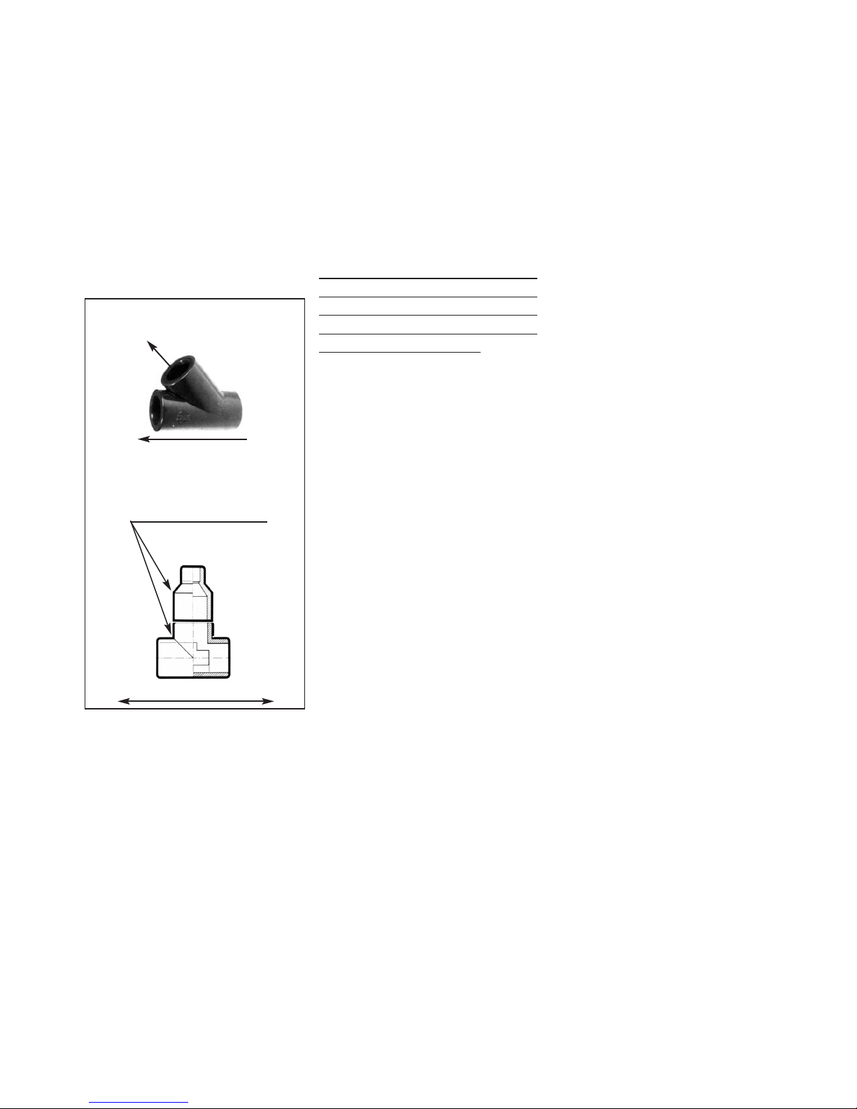
1) ELBOWS
Only use large radius elbows and not short
radius. Short radius elbows entail a flowrate loss of approx. 2.5% per elbow. A succession of 8 short radius elbows will therefore result in total flow-rate reduction of
100% x0.975x0.975x0.975x0.975 etc =
81.66%.
Large radius elbows only result in a flowrate loss of approx. 0.5%.
If no large radius elbows can be found use
2 successive 45° elbows instead.
See also photo to the left.
CHILLED WATER CIRCUIT PIPING
GOLDEN RULES - INSTALLATION OF BASIC COMPONENTS
= SHUT-OFF VALVE
Secondary access with shutoff valve 3/4” - should
always face upwards
Drain valve at lowest part of circuit. Allows full draining of the system after initial pressure tests and also in case of doubt concerning
the exact glycol (anti-freeze) percentage of the mixture.
SHUT-OFF VALVES ON ENTRY AND EXIT
FOR EASY MAINTENANCE
If this line always goes upwards without any down-turn, it can be
used for filling the system ; if not use secondary access and attach
temporary filling hose with temporary filling tank on rooftop, up
and above highest air-handler. Diam. 5/8” or 3/4” transparent.
OPTIONAL RETURN LINE VALVE
LARGE RADIUS ELBOWS ONLY
CIRCULATION PUMP
EXPANSION TANK : If
static- should be highest
part of circuit
8.2 - ELBOWS 90° - CHILLED WATER PIPING
SHORT RADIUS ELBOW
USE LARGE RADIUS
ELBOW ONLY OR 2 X
45° ELBOWS
2) PIPE INSULATION
Only use rubber or synthetic rubber foam
insulation (Armstrong Armaflex or
Rubatex or similar) - do not use polythene
foam insulation.
Do not use split-type open insulation as
this type tends to come apart after a certain
time.
Try to use rigid foam core supports to fix
piping.
See also photo to the right.
8.3 - EXAMPLE WATER PIPING CIRCUIT - 1 CHILLER UNIT + 4 AIR-HANDLERS
FOAM THICKNESS : 9 MM FOR
BOATS UP TO 15/16 M; 13 MM
FOR BOATS OVER 16 ML.
RIGID CORE SPECIAL SUPPORT
ENABLING SOLID FIXING OF TUBING WITHOUT DEFORMATION
ONLY USE RUBBER OR SYNTHETIC
RUBBER FOAM INSULATION
8.4 - TUBING INSULATION
Here-after a summary of the most basic but important guide-lines for success when installing a Chiller piping
System. These Guide-lines cover all items such as insulation, water-piping, etc
Most important pre-liminary remark :
Water-flow rates in a Chiller circulation circuit are approx. 2/3 times as high as the normal flow rates found
a central heating system at home. So pay special attention to all possible flow restrictions !
Page 15
2004 SERIES - CHILLER SYSTEMS - OPERATION AND INSTALLATION MANUAL - PAGE : 14
2004 SERIES - CHILLER SYSTEMS - OPERATION AND INSTALLATION MANUAL - PAGE : 14
EDITION DATED 21ST AUGUST 2006
Insulation foam thickness should be at
least 9 mm for boats up to 15/16 ml and 13
mm for all boats above that length.
Finish off all Tee junstions and others with
self-adhesive foam tape.
3) TEE JUNCTIONS
It is preferable to use oblique Tee junctions
for secondary branching. If 45° Tees are
not available make sure the reduction in
diam. on the secondary line is made after
the junction Tee so as to obtain the largest
possible entry diam.
See photo here-under.
4) ENTRY DIAM. OF AIR-HANDLERS
Always respect the minimum entry diam.
of the air-handlers. Secondary piping to the
air-handlers should not be less than the
prescribed diam.
Here-after list of air-handler entry diameters (all diam. are net internal) :
Model Entry/Exit diam.
4000/4500 BTU 12 mm (1/2”)
6000 BTU 12 mm
9000 BTU 15 mm (5/8”)
12000 BTU 15 mm
16000 BTU 15 mm
24000 BTU 20 mm (3/4”)
5)
ANTI-FREEZE SOLUTION :
It is imperative to add approx. 25% pure glycol to the chilled water-circuit system so as to
avoid accidental freezing of the water-circuit
during the winter and also freezing up of the
condensing unit evaporator(s) should for any
reason the temperature control fail or be
retarded.
There is a general safety cut-out when freezing up an evaporator by means of the Low
Pressure cut-out, but this safety device may
allow a temporary drop of the water-circuit
temperature to approx. -2° C before stopping
the system. Hence the utmost importance of
adding approx. 20% glycol to the water-circuit.
Attention : non-respect of the use of
glycol/water mixture (25% glycol +
75% fresh water) in the chilled
water circulation circuit will void
any WEBASTO warranty.
6) FILLING UP AND PURGING OF A
CHILLED WATER CIRCUIT :
The following procedure is the simplest and
most effective way to prepare a chilled water
circuit, purge it from all air and put it into
operation in the shortest possible time.
Make sure to follow the steps here-under in
the same order :
1) Installation of purging Tee on entry/suction side of circulation pump. This Tee
should enable the temporary connection of a
filling hose of at least 15 mm interior diam.
The filling entry should be directed upwards
and not side-ways or down-wards.
Fit a shut-off valve enabling quick closing of
the access point after completing the filling
procedure.
2) Install a temporary charging recipient (jerrycan etc) in such a way that this recipient is
the highest point of the circuit and that the
hose from the acces Tee to the jerrycan goes
always upwards, never horizontally and
never downwards. It is advisable to use transparent hose from the Tee to the jerrycan.
3) Open all bleeders on all air-handlers.
4) Start filling the circuit from the jerrycan
on the rooftop - watch all bleeder points on
all air-handlers. Close all bleeders immediately when solid water comes out. No further
bleeding from the air-handlers will be
required from there on.
5) Isolate the 230V supply to the circulation
pump so as to be able to switch the circulation pump on and off manually. The easiest
method is to connect a temporay lead to the
circulation pump with a manual switch.
Make sure the jerrycan on the roof is at least
half full at that stage.
Start circulation pump shortly for approx. 15
seconds and stop it. You will notice massive
air bubbles going upwards through the filling
hose.
Repeat this for several times until such
moment that the air bubbles going upwards
through the filling hose become small
enough to leave the pump on continuously
without cavitating.
6) Leave the pump on continuously for at
least 45 minutes. You will notice a contiuous
small stream of bulbles going upwards and
solid water going downwards.
7) Help the final purging of the system by
selectively closing the shut-off valves on all
air-handlers so as to force the waterflow
through the other air-handlers. This will finish purging any residual air that may have
been trapped in any individual air-handler.
8) When the pump is running without any
cavitation noise and no further small air-bubbles go upwards from the Tee junction on the
pump entry, stop the circulation pump, close
the shut-off valve and disconnect the temporary filling station.
9) With this method there is absolutely no
need to purge at each individual air-handler
provided the filling hose has a sufficiently
large diameter and always goes upwards to
the filling tank on the rooftop.
10) Remark for pressurized systems only
After satisfactory purging of all air in the system, close valve on Tee entry to the suction
pump with pump running so as to build up
maximum pressure in the system.
Then if necessary increase pressure by opening valve to pressurized water system.
11) Refilling after leak :
Never refill system with fresh water only; be
sure to always maintain glycol mixture of
between. 20 and 25% glycol - 75/80% fresh
water.
WATER-FLOW - MAIN BRANCH
WATER-FLOW - SECONDARY
8.5 - TEE JUNCTIONS
45° TEE
JUNCTION
90° TEE JUNCTION
WATER-FLOW
LEAVE AMPLE ROOM BEFORE
REDUCING PIPE DIAMETER
Page 16

2004 SERIES - CHILLER SYSTEMS - OPERATION AND INSTALLATION MANUAL - PAGE : 15
2004 SERIES - CHILLER SYSTEMS - OPERATION AND INSTALLATION MANUAL - PAGE : 15
EDITION DATED 21ST AUGUST 2006
9. ROUTINE CHECKS
CHILLED WATER
CIRCULATION PUMP
- SHUT-OFF VALVE
1
23
4
5
6
1 = 24000 BTU
2 = AIR-HANDLER 12000 BTU - SALOON
3 = AIR-HANDLER 6000 BTU - OWNERS CABIN
4 = AIR-HANDLER 4500 BTU - GUEST CABIN
5 = AIR-HANDLER 4500 BTU - GUEST CABIN
6 = EXPANSION TANK
D12 = INTERIOR DIAM. 12 MM - 1/2"
D15 = INTERIOR DIAM. 15 MM - 5/8"
D20 = INTERIOR DIAM. 20 MM - 3/4"
D20
D15
D12
D20
D15
D15
D15
D15
D20
D12
D12
D12
D12
D12
8.7 - EXAMPLE N° 2 - MONO-HULL WITH WBCP24/D - STERN LOCATION + 4 AIR-HANDLERS
TYPICAL SCHEMATICAL EXAMPLES OF CHILLED WATER CIRCUITS
Here-after a certain number of examples of typical chilled water circuit piping lay-outs
- SHUT-OFF VALVE
CHILLED WATER CIRCULATION
PUMP
EXPANSION TANK
D12 = INTERIOR DIAM. 15 MM - 5/8"
D15 = INTERIOR DIAM. 12 MM - 1/2"
D15
D12D12
D15
D12
D12
D15
18000 BTU
AIR-HANDLER
9000 BTU
AIR-HANDLER
9000 BTU
8.6 - EXAMPLE N° 1 - SMALL 18000 BTU CHILLER - CENTRAL LOCATION + 2 AIR-HANDLERS
Page 17

2004 SERIES - CHILLER SYSTEMS - OPERATION AND INSTALLATION MANUAL - PAGE : 16
2004 SERIES - CHILLER SYSTEMS - OPERATION AND INSTALLATION MANUAL - PAGE : 16
EDITION DATED 21ST AUGUST 2006
- SHUT-OFF VALVE
36000 BTU
FLOW CALIBRATION VALVES
1
2
3
4
5
6
7
1 = CHILLED WATER CIRCULATION PUMP
2 = 12000 BTU AIR-HANDLER - MAIN SALOON
3 = 12000 BTU AIR-HANDLER - MAIN SALOON
4 = 6000 BTU CABIN AIR-HANDLER
5 = 6000 BTU CABIN AIR-HANDLER
6 = 6000 BTU CABIN AIR-HANDLER
7 = 6000 BTU CABIN AIR-HANDLER
8 = EXPANSION TANK
9 = RETURN COLLECTOR 4 + 1
D12 = INTERIOR DIAM. 12 MM - 1/2"
D15 = INTERIOR DIAM. 15 MM - 5/8"
D20 = INTERIOR DIAM. 20 MM - 3/4"
8
D20
D20
D15
D15
D15
D15
D15
D15
D15
D15
D15
D15
D20
D20
D12
D12
D12
D12
D12 D12
D12 D12
9
8.8 - EXAMPLE N° 3 - CATAMARAN WITH WBCP36/D - CENTRAL LOCATION + 6 AIR-HANDLERS
Page 18

2004 SERIES - CHILLER SYSTEMS - OPERATION AND INSTALLATION MANUAL - PAGE : 17
2004 SERIES - CHILLER SYSTEMS - OPERATION AND INSTALLATION MANUAL - PAGE : 17
EDITION DATED 21ST AUGUST 2006
1
2
3
4
5
6
7
8
9
10
1 = 72000 BTU
2 = EXPANSION TANK
3 = CHILLED WATER CIRCULATION PUMP
4 = 16000 BTU AIR-HANDLER - WHEELHOUSE
5 = 16000 BTU AIR-HANDLER - MAIN SALOON
6 = 12000 BTU AIR-HANDLER - OWNERS CABIN
7 = 9000 BTU AIR-HANDLER - GUEST CABIN N˚1
8 = 9000 BTU AIR-HANDLER - GUEST CABIN N˚ 2
9 = 6000 BTU AIR-HANDLER - GUEST CABIN N˚ 3
10 = 6000 BTU AIR-HANDLER - GUEST CABIN N˚4
D12 = INTERIOR DIAM. 12 MM - 1/2"
D15 = INTERIOR DIAM. 15 MM - 5/8"
D20 = INTERIOR DIAM. 20 MM - 3/4"
D25 = INTERIOR DIAM. 25 MM - 1"
- SHUT-OFF VALVE
SOLENOID VALVE WITH
METERED BY-PASS
D25
D25
D25
D25
D20
D20
D20
D20
D20
D20
D15
D15
D15
D15
D12
D12
D12
D12
LENGTHS TO COMMON
EXIT AND ENTRY SHOULD
BE BALANCED
8.9 - EXAMPLE N° 4 - M/Y WITH WBCP72/D TWIN - STERN LOCATION + 10 AIR-HANDLERS
Page 19

2004 SERIES - CHILLER SYSTEMS - OPERATION AND INSTALLATION MANUAL - PAGE : 18
2004 SERIES - CHILLER SYSTEMS - OPERATION AND INSTALLATION MANUAL - PAGE : 18
EDITION DATED 21ST AUGUST 2006
8F - AIR DUCTING - VENTILATION
1) MINIMUM AIR-GRILLE SECTIONS
In order to obtain an acceptable noise level at
max. blower speed certain requirements as
regards grille and ducts sections should be
observed.
Also the size of the transition boxe behind
the supply air-grille is important.
See table here-under to choose correct grille
sections according to BTU rating.
2) DUCT TYPE
Flexible air-ducts should be of high quality
with sufficiently strong steel spiral reinforcement to avoid accidental crushing.
Spiral type ducts should be extended to their
maximum possible length to obtain max.
interior smoothness.
For very long duct sections preference should
be given to rigid ducts (in PVC for example)
which offer a far greater smoothness than
flexible spiral type ducting and therefore will
greatly reduce internal friction.
For very short lengths non-insulated ducts
may possibly be used. Over greater lengths it
is advisable to use insulted type ducts to
avoid condensation on the outside of the airducts.
AIR/HANDLER-WBCC SUPPLY AIR GRILLE RETURN AIR GRILLE DUCT DIAM. DUCT DIAM.
MODEL MODEL/ SECTION cm² MODEL/SECTION cm² <1.8 M DUCT LEN. >1.8 M DUCT LEN.
4000/4500 BTU
6000 BTU
9000 BTU
12000 BTU
16000 BTU or
16000 BTU
24000 BTU
32000 BTU
1 x 8x4” 150 cm²
1 x 10x4” 190 cm²
1 x 12x4” 235 cm²
1 x 10x5” 250 cm²
1 x 12x6” 390 cm²
2 x 10x4” 380 cm²
2 x 10x5” 500 cm²
2 x 12x5” 650 cm²
1 x 12x5” 325 cm²
1 x 11x8” 490 cm²
1 x 11x8” 490 cm²
1 x 14x7” 550 cm² or
1 x 14x10” 800 cm2
1 x 14x12” 1000 cm²
2 x 14x10” 1600 cm²
80 mm
100 mm
100 mm
125 mm
125 mm
125 mm
2 x 125 mm
2 x 125 mm
100 mm
125 mm
125 mm
150 mm
150 mm
150 mm
2 x 150 mm
2 x 150 mm
3) BLOWER OUTLETS
90° turns with flexible ducts directly from
blower outlets should be avoided at all costs
as they introduce severe restrictions in the
air-flow.
All WEBASTO blowers (except on 24000
BTU models) can be rotated through 45°
steps so as to obtain a straight-line outlet
from the blower. This facility should be used
whenever possible.
See also drawing to the right.
4) TRANSITION BOXES
Transition boxes behind supply air-grilles
essentially serve the following purpose :
Serve as an expansion volume for the airflow to be reduced in velocity and therefore
reduce air noise when crossing the outlet
louvres.
It follows therefore that the depth of the transition box is an important factor to allow dispersion of the air-flow
The table to the right gives the necessary
information as to the minimum dimensions
advisable for such transition boxes.
5) RETURN GRILLE OFFSET
It is best to avoid placing a return air grille
directly opposite the finned coil surface of an
air-handler. This will inevitably allow propagation of direct blower-motor noise through
the grille.
Always try to offset the grille so as to chicane the return air to the coil inlet.
This will lower direct noise propagation in a
significant manner.
AIR FLOW
AIR FLOW
BLOWER ROTATED TO
MINIMZE FRICTON LOSSES
H
H
DUCT DIAM. MINIMUM VALUE OF “H”
80 mm 100 mm
100 mm 120 mm
125 mm 140 mm
150 mm 165 mm
8.11 - TRANSITION BOX INFORMATION
Deflection curve for longitudinal
entry transition boxes
NB : For duct lengths over 1.80 ml, it may be possible to use the nominal duct diameter (for example 100 mm - 6000 BTU
model), if instead of spiral type flexible ducts, rigid perfectly smooth interior ducts are used.
8.10 - ROTATABLE BLOWER OUTLETS
Page 20

2004 SERIES - CHILLER SYSTEMS - OPERATION AND INSTALLATION MANUAL - PAGE : 19
2004 SERIES - CHILLER SYSTEMS - OPERATION AND INSTALLATION MANUAL - PAGE : 19
EDITION DATED 21ST AUGUST 2006
When starting up an air conditioning unit it is
advisable to carry out a certain number of
control routines to ensure proper functioning
of the unit.
- always check (especially after a long
absence) the functioning of the sea water
cooling system. Immediately stop the system
if no sea-water comes out of the pump exit
after compressor starts up.
- periodically check the air filter in the return
air grilles. Clean if necessay.
- check condensation drain from the evaporator drain pan.
- take care not to damage the air-ducts. A
damaged air-duct may stop air flow through
the evaporator, freeze up the evaporator and
subsequently damage the compressor.
- when preparing for winter lay-up take care
to rince all sea-water circuits with a freshwater/glycol solution (20% or more depending on local winter conditions).
10.TROUBLE SHOOTING
1) No sign of live : check main electrical supply, fuses, etc.
2) The digital display shows 3 lettres
<AAA>. This means a persistent state of low
voltage (less than 195 V AC). The system
will re-start as soon as the voltage level
climbs above cut-out level and the system
will then re-start after a time-delay of 1
minute approx.
3) The compressor will start but no sea-water
circulation can be observed :
- check sea-cock to sea-water pump.
- check sea-water strainer
- check if pump turns
- if the pump does not turn with the compressor working, check power-supply from
the main control unit box to the pump.
4) Compressor and pump work but no correct
operation in either cool or heat cycle :
- during the heat cycle with too slow a seawater circulation you may actually freeze up
the sea-water in the cupro-nickel condenser
and completely block the system.
- check voltage level. Do not operate a system with a persistent voltage level below
195 V AC.
- check freon charge if operation is still not
satisfactory, after having checked all the
above points.
5) The compressor works but is subject to
intermittent stops without having attained
the desired set-point temperature.
- the HP and BP (if present) pressure safety
switches stop the compressor because of
abnormal working pressures either on the
high or on the low side. Check proper functioning of the cooling circuit. Check ventilator/blower system for obstructions.
- incorrect freon charge (over-charge or
insufficient charge level).
See also here-above : Error
codes/interrupted system operation.
6) The heat cycle takes very long to get started.
- normal if the sea-water temperature is very
low. If sea-water temperature drops below
approx. 8° C. the heat cycle becomes much
less effective and takes long to get properly
started.
7) The heat cycle functions very well but the
compressors stops by means of the high
pressure safety switch.
- the heat cycle functions with a very high
sea-water temperature and therefore the
high pressure side exceeds the safety limit.
You may try to remedy this situation by
slightly restricting the sea-water flow but not
so much as to freeze up the condenser. Do
not forget to open up the sea-water circulation again when switching back to
<COOL>.
Page 21

2004 SERIES - CHILLER SYSTEMS - OPERATION AND INSTALLATION MANUAL - PAGE : 20
2004 SERIES - CHILLER SYSTEMS - OPERATION AND INSTALLATION MANUAL - PAGE : 20
EDITION DATED 21ST AUGUST 2006
11 - WIRING DIAGRAMS - ALL CHILLER MODELS Page
11.1 - Wiring Diagram single/twin compressor WBCP16/30 - 1 phase .....................................
11.2 - Wiring Diagram Compressors 1 and 2 - 1 or 3 phase ....................................................
11.3 - Wiring Diagram Compressors 3 and 4 - 1 or 3 Phase ....................................................
11.4 - Wiring schematics -supply cables for TWIN/CI compressor units - single phase ..........
11.5 - Wiring schematics - supply cables for TRI/CI (3) compressor units - single phase ......
11.6 - Wiring schematics - supply cables for TRI/CI (3) compressor units - 3 phase ..............
11.7 - Wiring schematics - supply cables for QUATRO/CI (4) compressor units - 3 phase .....
11.8 - Wiring Diagram - automatic staging relay - secondary AC loads ..................................
11.9 - Wiring Diagram - blower motor running capacitors .......................................................
Minimum Cable Sections per Chiller Model (Ground Wires not shown) :
Model Description Voltage Phase Section mm2
SINGLE COMPRESSOR UNITS
WBCP20 230 1 2 x 2.5 mm2
WBCP24 230 1 2 x 2.5 mm2
WBCP30 230 1 2 x 4 mm2
WBCP36 230 1 2 x 4 mm2
WBCP42 230 1 2 x 6 mm2
WBCP48 230 1 2 x 6 mm2
TWIN COMPRESSOR UNITS (CI models - 2 independent refrigerant circuits)
(Section per Compressor - for single supply line increase section accordingly)
WBCP40/D TWIN 230 1 2 x 2.5 mm2
WBCP52/D TWIN 230 1 2 x 2.5 mm2
WBCP64/D TWIN 230 1 2 x 4 mm2
WBCP72/D TWIN 230 1 2 x 4 mm2
WBCP84/D TWIN 230 1 2 x 6 mm2
WBCP96/D TWIN 230 1 2 x 6 mm2
WBCP84/D TWIN 400 3 3 x 2.5 mm2
WBCP96/D TWIN 400 3 3 x 2.5 mm2
TRI-COMPRESSOR UNITS (CI models - 3/4 independent refrigerant circuits)
(Section per Compressor - for single supply line increase section accordingly)
WBCP108/D TRI 230 1 2 x 4 mm2
WBCP126/D TRI 230 1 2 x 6 mm2
WBCP126/D TRI 400 3 3 x 2.5 mm2
WBCP144/D TRI 230 1 2 x 6 mm2
WBCP144/D TRI 400 3 3 x 2.5 mm2
WBCP180/D TRI 400 3 3 x 4 mm2
WBCP216/D TRI 400 3 3 x 4 mm2
WBCP252/D TRI 400 3 3 x 6 mm2
WBCP288/D QUATRO 400 3 3 x 4 mm2
WBCP336/D QUATRO 400 3 3 x 6 mm2
21
22
23
24
24
25
25
26
26
Page 22

220V
220V
COMP1
PUMP2
FAN
VA LV E
PUMP1
PUMP2
COMP2
COMP1
FAN
VA LV E
PUMP1
HP
BP
HP
BP
AC SUPPLY 230V
SEAWATER PUMP
CIRCULATION PUMP
BLOWER
C1R1T1
C2
R2
T2
RUN
CAPA
REVER. VALVE
S
R
C
DIGIT.
DISPL.
AIR
SENSOR
WATER
SENSOR
GND
+
-
DIPSWITCH SELECTOR
CYCLE
INDICATOR RELAY
AC LOAD
STAGING RELAY
2004 SERIES - CHILLER SYSTEMS - OPERATION AND INSTALLATION MANUAL - PAGE : 21
2004 SERIES - CHILLER SYSTEMS - OPERATION AND INSTALLATION MANUAL - PAGE : 21
EDITION DATED 21ST AUGUST 2006
11.1 - WIRING DIAGRAM WBCP UNITS - 230V 1 PHASE - 16000 TO 30000 BTU- 1 COMPRESSOR
(For single compressors 36 to 48000 BTU, a power-relay is used - refer to drawing 11.2 - page 22)
1
23
4
OPEN
ATT. DIPSWITCH SETTINGS
BLACK = PUSHED DOWN
Page 23

2004 SERIES - CHILLER SYSTEMS - OPERATION AND INSTALLATION MANUAL - PAGE : 22
2004 SERIES - CHILLER SYSTEMS - OPERATION AND INSTALLATION MANUAL - PAGE : 22
EDITION DATED 21ST AUGUST 2006
DIPSWITCH SELECTOR
AC SUPPLY 230V/ELECTRONICS/PUMPS
AC SUPPLY COMPR. 2
TO COMPR. 2
SEAWATER PUMP
CIRCULATION PUMP
BLOWER
REVER.VALVES
HP
BP
HP
BP
AC SUPPLY COMPR. 1
TO COMPR. 1
C1
R1T1C2
R2
T2
GND
PUMP1
PUMP2
VA LV E
FAN
COMP2
COMP1
PUMP2
230V
230V
FAN
COMP1
COMP2
VA LV E
PUMP1
POWER-RELAY
COMPR. 2 - CAN
BE SINGLE PHASE
OR 3 PHASE,
ACCORDING TO
COMPRESSOR
CHOICE
POWER-RELAY
COMPR. 1 - CAN
BE SINGLE PHASE
OR 3 PHASE,
ACCORDING TO
COMPRESSOR
CHOICE
CYCLE
INDICATOR RELAY
AC LOAD
STAGING RELAY
BP
BP
HP
HP
11.2 - WIRING DIAGRAM WBCP CONDENSING UNITS - 1/3 PHASE - COMPRESSORS 1 AND 2
1
23
4
OPEN
ATT. DIPSWITCH SETTINGS
BLACK = PUSHED DOWN
Page 24
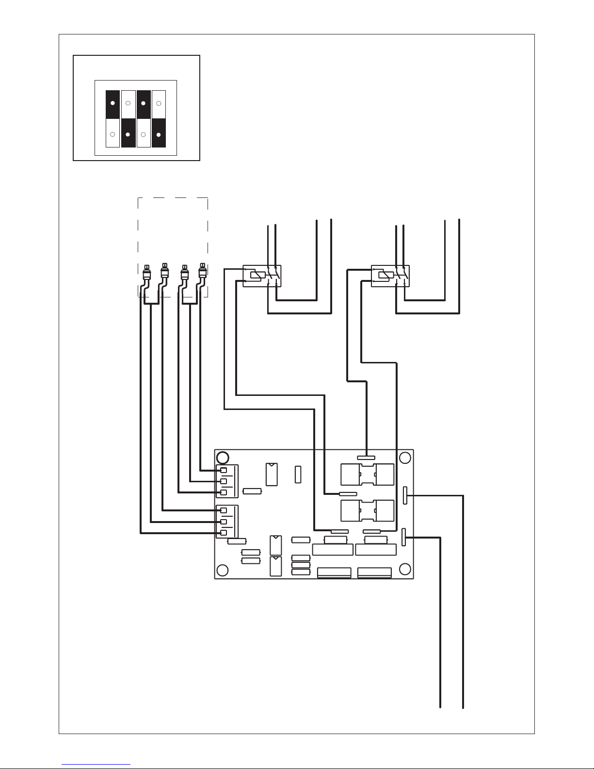
2004 SERIES - CHILLER SYSTEMS - OPERATION AND INSTALLATION MANUAL - PAGE : 23
2004 SERIES - CHILLER SYSTEMS - OPERATION AND INSTALLATION MANUAL - PAGE : 23
EDITION DATED 21ST AUGUST 2006
HP
BP
HP
BP
230V
COMP3
COMP3
COMP4
COMP4
TO CONNECTORS 230V - TECC MAIN BOARD
HP - COMP3
BP - COMP3
HP - COMP4
BP - COMP4
AC SUPPLY COMP3
AC SUPPLY COMP4
TO COMP3
TO COMP4
POWER-RELAY
SINGLE PHASE OR
3 PHASE AS REQUIRED
POWER-RELAY
SINGLE PHASE OR
3 PHASE AS REQUIRED
11.3 - WIRING DIAGRAM WBCP CONDENSING UNITS - 1/ 3 PHASE - COMPRESSORS 3 AND 4
1234
OPEN
ATT. DIPSWITCH SETTINGS
BLACK = PUSHED DOWN
Page 25

2004 SERIES - CHILLER SYSTEMS - OPERATION AND INSTALLATION MANUAL - PAGE : 24
2004 SERIES - CHILLER SYSTEMS - OPERATION AND INSTALLATION MANUAL - PAGE : 24
EDITION DATED 21ST AUGUST 2006
MAIN SUPPLY COMPR. 1
MAIN SUPPLY COMPR. 2
MAIN SUPPLY TECC + ACCESSORIES
TO CONNECTORS 230 AC IN - TECC CARD
TO CONNECTORS COMP2 - TECC CARD
TO CONNECTORS COMP1 - TECC CARD
TO THE RIGHT OF DASHED LINE : PREWIRED BY FACTORY
TO THE LEFT OF DASHED LINE - TO BE WIRED BY CLIENT
POWER RELAY COMPRESSOR 1
POWER RELAY COMPRESSOR 2
CLD TERMINAL CONNECTION STRIP INSIDE ELECTRICAL BOX
PH
N
T
C2
C2
C1
C1
11.4 - POWER-SUPPLY SCHEMATICS - CHILLER UNITS TWIN/CI - SINGLE PHASE 230V
POWER RELAY COMPR. 1
POWER RELAY COMPR. 2
POWER RELAY COMPR. 3
TO CONNECTORS COMP1 - TECC CARD
TO CONNECTORS COMP2 - TECC CARD
TO CONNECTORS COMP3 - TECC CARD
TO CONNECTORS AC230 IN - TECC CARD
CLD TERMINAL CONNECTION STRIP INSIDE ELECTRICAL BOX
TO THE RIGHT OF DASHED LINE : PREWIRED BY FACTORY
TO THE LEFT OF DASHED LINE : TO BE WIRED BY CLIENT
POWER SUPPLY TECC CARD + ACCESS.
POWER SUPPLY COMPRESSOR 3
POWER SUPPLY COMPRESSOR 2
POWER SUPPLY COMPRESSOR 1
T
N
PH
C3
C3
C2
C2
C1
C1
11.5 - POWER-SUPPLY SCHEMATICS - CHILLER UNITS TRI/CI - SINGLE PHASE 230V
Page 26

2004 SERIES - CHILLER SYSTEMS - OPERATION AND INSTALLATION MANUAL - PAGE : 25
2000 SERIES - CHILLER SYSTEMS - OPERATION AND INSTALLATION MANUAL - PAGE : 25
EDITION DATED 21ST AUGUST 2006
CLD TERMINAL CONNECTION STRIP INSIDE ELECTRICAL BOX
POWER RELAY COMPRESSOR 1
POWER REALY COMPRESSOR 2
POWER RELAY COMPRESSOR 3
TO CONNECTORS COMP1 - TECC CARD
TO CONNECTORS COMP2 - TECC CARD
TO CONNECTORS COMP3 - TECC CARD
TO THE RIGHT OF DASHED LINE : PREWIRED BY FACTORY
TO THE LEFT OF DASHED LINE :TO BE WIRED BY CLIENT
MAIN SUPPLY COMPR. 1
MAIN SUPPLY COMPR. 2
MAIN SUPPLY COMPR. 3
MAIN SUPPLY TECC CARD + ACCESSORIES
TO CONNECTORS 230AC IN - TECC CARD
PH
N
C3
C3
C3
C2
C2
C2
C1
C1
C1
T
11.6 - POWER-SUPPLY SCHEMATICS - CHILLER UNITS TRI/CI - 3 PHASE 400V
11.7 - POWER-SUPPLY SCHEMATICS - CHILLER UNITS QUATRO/CI - 3 PHASE 400V
TO THE RIGHT OF DASHED LINE : PREWIRED BY WEBASTO
TO CONNECTORS COMP1 - TECC CRD
TO CONNECTORS COMP2 - TECC CRD
TO CONNECTORS COMP3 - TECC CRD
TO CONNECTORS COMP4 - TECC CRD
TO THE LEFT OF DASHED LINE : TO BE WIRED BY CLIENT
WEBASTO TERMINAL STRIP INSIDE WEBASTO ELECTRICAL BOX
TO CONNECTORS 230AC IN - TECC CARD
MAIN SUPPLY
COMPR. 1
POWER RELAY
COMPR. 1
POWER RELAY
COMPR. 2
POWER RELAY
COMPR. 3
POWER RELAY
COMPR. 4
MAIN SUPPLY
COMPR. 2
MAIN SUPPLY
COMPR. 3
MAIN SUPPLY
COMPR. 4
MAIN SUPPLY TECC CARD + ACCESS.
Page 27

2004 SERIES - CHILLER SYSTEMS - OPERATION AND INSTALLATION MANUAL - PAGE : 26
2004 SERIES - CHILLER SYSTEMS - OPERATION AND INSTALLATION MANUAL - PAGE : 26
EDITION DATED 21ST AUGUST 2006
11.9 - WIRING SCHEMATICS - RUNNING
CAPACITORS FOR BLOWER MOTERS -
ECOFIT/EBM
PHASE
NEUTRAL
BROWN
WIRE
CONNECTION
BLACK
BLACK
GND WIRE
CABLE FROM
BLOWER MOTER
BLUE
230V SUPPLY
RUNNING
CAPACITOR
230V POWER-RELAY CONTACTS NORMALLY CLOSED
230V ON-BOARD SUPPLY - TO AUTOMATICALLY STAGED FUNCTIONS
DELESTAGE
TECC - CHILLER - CONTROLLER CARD
11.8 - WIRING SCHEMATICS -
AUTOMATIC STAGING RELAY - SECONDARY
230V ON-BOARD FUNCTIONS
11.9 - WIRING SCHEMATICS -
Connection 3-Way valve (Lizhan/Zhongli) on TECC card
 Loading...