


List of Contents |
Air Top 2000 |
Air Heater
Air Top 2000 S D (Diesel) Air Top 2000 S B (Gasoline)
Service and Repair Manual
–Improper installation or repair of Webasto heating and cooling systems can cause fire or the leakage of deadly carbon monoxide leading to serious injury or death.
–Installation and repair of Webasto heating and cooling systems requires special Webasto training, technical information, special tools and special equipment.
–NEVER attempt to install or repair a Webasto heating or cooling system unless you have successfully completed the factory training course and have the technical skills, technical information, tools and equipment required to properly complete the necessary procedures.
–ALWAYS carefully follow Webasto installation and repair instructions and heed all WARNINGS.
–Webasto rejects any liability for problems and damage caused by the system being installed by untrained personnel.

Air Top 2000 S |
List of Contents |
|
|
List of Contents
1.Introduction
1.1 |
Scope and Purpose................................................................................................................................. |
101 |
|
|
1.1.1 |
Use of Air Heaters....................................................................................................................... |
101 |
1.2 |
Meaning of Warnings, Cautions, and Notes............................................................................................ |
101 |
|
1.3 |
Additional Documentation to be used...................................................................................................... |
101 |
|
1.4 |
Safety Information and Regulations ........................................................................................................ |
101 |
|
|
1.4.1 |
General Safety Notes.................................................................................................................. |
101 |
1.5 |
Legal Provisions for Installation............................................................................................................... |
102 |
|
2.General Description
2.1 |
Combustion and Heating Air Fan ............................................................................................................ |
201 |
2.2 |
Heat Exchanger....................................................................................................................................... |
202 |
2.3 |
Burner Insert with Combustion Tube....................................................................................................... |
202 |
2.4 |
Control Unit / Control Circuit Board ......................................................................................................... |
202 |
2.5 |
Flame Sensor .......................................................................................................................................... |
203 |
2.6 |
Glow Plug ................................................................................................................................................ |
203 |
2.7 |
Temperature Limiter ................................................................................................................................ |
203 |
2.8 |
Dosing Pump........................................................................................................................................... |
203 |
3.Functional Description
|
3.1 Functional Description Air Top 2000 S ....................................................................................................... |
301 |
|
|
3.1.1 |
Control Element .......................................................................................................................... |
301 |
|
3.1.2 |
Switch-On.................................................................................................................................... |
301 |
|
3.1.3 |
Stabilization................................................................................................................................. |
301 |
|
3.1.4 |
Heating Operation....................................................................................................................... |
302 |
|
3.1.5 |
Control Operation........................................................................................................................ |
302 |
|
3.1.6 |
Control Idle.................................................................................................................................. |
302 |
|
3.1.7 |
Switch-Off.................................................................................................................................... |
302 |
|
3.1.8 |
Switch-Off upon Failure............................................................................................................... |
302 |
4. |
Technical Data ............................................................................................................................................... |
401 |
|
5.Troubleshooting
5.1 |
General.................................................................................................................................................... |
501 |
5.2 |
General Failure Symptoms...................................................................................................................... |
501 |
5.3 |
Failure Symptoms during Operation........................................................................................................ |
502 |
5.4 |
Error Code Output ...................................................................................................................................... |
503 |
6.Functional Tests
6.1 |
General.................................................................................................................................................... |
601 |
6.2 |
Adjustments............................................................................................................................................. |
601 |
|
6.2.1 Adjustment of the CO2 Contents................................................................................................. |
601 |
6.3 |
Components Testing ............................................................................................................................... |
602 |
|
6.3.1 Glow Plug Resistance Test ......................................................................................................... |
602 |
|
6.3.2 Flame Sensor Resistance Test ................................................................................................... |
602 |
|
|
I |

List of Contents |
Air Top 2000 S |
|
|
7.Circuit Diagrams
7.1 General.................................................................................................................................................... |
701 |
8.Servicing
8.1 |
General.................................................................................................................................................... |
801 |
|
8.2 |
Work on the Air Heater............................................................................................................................ |
801 |
|
8.3 |
Work on the Vehicle ................................................................................................................................ |
801 |
|
8.4 |
Air Heater Test Run................................................................................................................................. |
801 |
|
8.5 |
Servicing.................................................................................................................................................. |
801 |
|
8.6 |
Visual Inspections and Installation Regulations ...................................................................................... |
801 |
|
|
8.6.1 |
Heating Air System...................................................................................................................... |
801 |
|
8.6.2 |
Fuel Supply ................................................................................................................................. |
802 |
|
8.6.3 |
Dosing Pump............................................................................................................................... |
804 |
|
8.6.4 |
Fuel Filter .................................................................................................................................... |
804 |
|
8.6.5 |
Combustion Air Supply................................................................................................................ |
805 |
|
8.6.6 |
Exhaust Line ............................................................................................................................... |
805 |
|
8.6.7 Combustion Air Intake and Exhaust Lines .................................................................................. |
805 |
|
|
8.6.8 |
Electrical Connections................................................................................................................. |
806 |
8.7 |
Removal and Installation ......................................................................................................................... |
808 |
|
|
8.7.1 Air Heater, Removal and Installation........................................................................................... |
808 |
|
8.8 |
Start-Up................................................................................................................................................... |
808 |
|
9.Repair
9.1 |
General.................................................................................................................................................... |
901 |
|
9.1.1 Work on Components after Disassembly.................................................................................... |
901 |
|
9.1.2 Incorporation of Modifications ..................................................................................................... |
901 |
9.2 |
Disassembly and Assembly..................................................................................................................... |
902 |
|
9.2.1 Removal of Housing Components/Covers.................................................................................. |
902 |
|
9.2.2 Replacement of Control Unit....................................................................................................... |
903 |
|
9.2.3 Replacement of Temperature Limiter.......................................................................................... |
903 |
|
9.2.4 Replacement of Combustion Air Fan .......................................................................................... |
905 |
|
9.2.5 Replacement of Flame Sensor.................................................................................................... |
907 |
|
9.2.6 Replacement of Glow Plug.......................................................................................................... |
907 |
|
9.2.7 Replacement of Burner Insert, Combustion Tube, and Heat Exchanger.................................... |
910 |
10.Packaging/Storage and Shipping
10.1 General.................................................................................................................................................. |
1001 |
II

Air Top 2000 S |
List of Figures |
|
|
List of Figures
501 |
General Failure Symptoms ............................................................................................................................. |
501 |
502 |
Failure Symptoms during Operation ............................................................................................................... |
502 |
601 |
Adjustment of CO2 Contents .......................................................................................................................... |
601 |
701 |
Terminal Pin Assignment, Air Top 2000 S....................................................................................................... |
701 |
702 |
Circuit Diagram Automatic Control Air Top 2000 S, 12V/24V with Control D i a l ............................................ |
702 |
703 |
Circuit Diagram Automatic Control Air Top 2000 S, 12V/24V with Combination Timer .................................. |
703 |
704 |
Circuit Diagram Automatic Control Air Top 2000 S, |
|
|
12V/24V with Control Dial and Standard Timer .............................................................................................. |
704 |
705 |
Connection Diagram, Air Top 2000 S with Combination Timer..................................................................... |
705 |
801 |
Fuel Supply..................................................................................................................................................... |
802 |
802 |
Webasto Fuel Tank Tap ................................................................................................................................. |
803 |
803 |
Fuel Tapping from Plastic Tank (tapping via fuel drain plug).......................................................................... |
803 |
804 |
Fuel Tapping from Plastic Tank (tapping via fitting plate)............................................................................... |
803 |
805 |
Pipe/Hose Connection .................................................................................................................................... |
804 |
806 |
Dosing Pump, Installation Position and Attachment ....................................................................................... |
804 |
807 |
Fuel Filter........................................................................................................................................................ |
804 |
808 |
Exhaust Muffler, Direction of Flow .................................................................................................................. |
805 |
809 |
Exhaust Pipe Outlet, Installation Position ....................................................................................................... |
805 |
810 |
Weather Resistant Fuse Holder........................................................................................................................ |
806 |
811 |
Control D i a l ................................................................................................................................................... |
806 |
812 |
Pulling the Plug............................................................................................................................................... |
806 |
813 |
Example of an Installation............................................................................................................................... |
807 |
901 |
Removal of Housing Components/Covers...................................................................................................... |
902 |
902 |
Replacement of Control Unit and Temperature Limiter................................................................................... |
904 |
903 |
Replacement of Combustion Air Fan (Disassembly) ...................................................................................... |
905 |
904 |
Replacement of Combustion Air Fan (Assembly............................................................................................ |
906 |
905 |
Disassembly of Heat Exchanger (Sheet 1 of 2).......................................................................................... |
908 |
906 |
Disassembly of Heat Exchanger (Sheet 2 of 2).......................................................................................... |
909 |
III

List of Figures |
Air Top 2000 S |
|
|
IV

Air Top 2000 S |
1 Introduction |
|
|
1.Introduction
1.1Scope and Purpose
This repair shop manual is intended to support familiarized personnel in the repair of the Air Top 2000 S.
1.1.1 Use of Air Heaters
The air heater Air Top 2000 S is used to
-heat the cabin
-defrost the windscreens.
They are not cleared for heating a transportation compartment for dangerous goods.
The heaters operate independent from the vehicle engine and are connected to the fuel tank and to the electrical system of the vehicle. Their use is possible in vehicles with wateror air-cooled engines.
1.2Meaning of Warnings, Cautions and Notes
WARNINGS, CAUTIONS, and NOTES in this manual have the following meaning:
WARNING
This heading is used to highlight that non-compliance with instructions or procedures may cause injuries or lethal accidents to personnel.
CAUTION
This heading is used to highlight that non-compliance with instructions or procedures may cause damage to equipment.
NOTE
This heading is used to highlight and draw specific attention to information.
1.3Additional Documentation to be used
This workshop manual contains all information and procedures necessary for the repair of the Air Top 2000 S.
The use of additional documentation is normally not necessary.
Operating instructions/installation instructions and the vehicle specific installation proposal may be used as complementary information as necessary.
1.4Safety Information and Regulations
The general safety regulations for the prevention of accidents and the relevant operating safety instructions have to be observed at all times."General Safety Regulations" beyond the scope of these regulations are detailed in the following.The specific safety regulations applicable to this manual are highlighted in the individual chapters by Warnings, Cautions, and Notes.
1.4.1 General Safety Notes
Within the scope of the StVZO (Road Licensing Regulations of the Federal Republic of Germany) “Design General Approvals”, laid down by the Federal Office for Motor Traffic, exist for the Air Top 2000 S with the following official marks of conformity:
-S 324 (Diesel) -S 325 (Gasoline)
The installation of the heater is to be performed in accordance with the installation instructions and must be checked in case of
a)the vehicle type inspection in accordance with
§20 StVZO
b)the individual inspection in accordance with
§21 StVZO or
c)the examination in accordance with § 19 StVZO performed by an officially authorised expert or examiner for road traffic, a vehicle inspector or a public
servant as per section 7.4 a of Annex VIII to the StVZO.
In the event of c) the installation must be certified on the acceptance certificate included in the copy of the “General Operating License” giving details about
-manufacturer
-type of vehicle , and
-vehicle identification number.
This validates the “Design General Approval”.
The acceptance certificate must be kept with the vehicle.
The year of first operation must be permanently marked on the identification label.
The heaters are cleared for heating the passenger and driver cabins but not for heating compartments intended for the transportation of dangerous goods.
101

1 Introduction |
Air Top 2000 S |
|
|
The heater must not be installed in the passenger or driver compartments of busses. Should the heater nevertheless be installed in such a compartment, the installation box must be sealed tight against the vehicle interior. There must be sufficient ventilation of the installation box from the exterior in order not to exceed a maximum temperature of 40 °C in the installation box.
At filling stations and fuel depots the heater must be switched off as there is a potential danger of explosion.
Where flammable fumes or dust may build up (e.g. in the vicinity of fuel, coal, wood, cereal depots, or similar installations) the heater must be switched off to prevent explosions.
Due to the danger of poisoning and suffocation the heater must not be operated in enclosed areas such as garages or workshops without exhaust venting, not even if the start-up is activated by the timer or telestart device.
When removing the heater the gasket below must be replaced.
The heat exchanger of the air heater remains serviceable for a maximum of 10 years and must then be replaced with an original spare part by the manufacturer or by one of its authorized workshops.
The heater must then be provided with a label marked with the sales date and with the words “Original Spare”.
Should exhaust pipes be routed through rooms accommodating persons, these pipes shall also be renewed after 10 years.
Installations not legally authorized will void the air heater’s “Official Marks of Conformity” and thus the vehicle’s permit of operation. The same applies for repairs performed by unskilled personnel and repairs with no original spare parts.
1.5Legal Provisions for Installation
For testing the heater in accordance with 19, 20, or 21 of the StVZO the following regulations are to be observed in particular (§ 22 a StVZO):
Testing is performed upon presentation of the operating and installation instructions of the manufacturer.
The year of the initial operation must be durably marked on the heater identification plate by the installing person.
Heating Air System
Heating air intake openings must be arranged so that under normal operating conditions exhaust fumes of the vehicle engine or air heater are not likely to be expected.
Extracting combustion air from the vehicle interior is not permissible.
Combustion Air Line
The combustion air required must be taken from the exterior.
Within rooms accommodating persons, the combustion air lines must not have more than four disconnects and a splash-water protected exterior wall feedthrough. The disconnects must be sealed in a way not to exceed a leak rate of 200 l/h at an overpressure of 0.5 mbar.
The line including feedthrough, disconnects, material and specific type must be described in the installation instructions.
The line must require tools for installation and removal, must be protected against damage, and must be shockproof.
Exhaust Line
Heaters must be designed to discharge the exhaust to the exterior.
Exhaust pipes must be routed so that exhaust fumes are unlikely to penetrate into the vehicle’s interior.
The function of any parts of the vehicle essential for its operation must not be impaired. Condensate or water penetrated must not be able to accumulate in the exhaust line.
Drain holes are permissible; these must drain the fluid to the exterior via lines sealed against the vehicle interior.
The exhaust line outlet is to be positioned to the top, to the side, or in case of exhaust venting below the vehicle floor, to the nearest possible location of the vehicle’s or cockpit’s side or rear end. In compartments accommodating persons, exhaust lines must not have more than one disconnect and must have a splash-water protected feedthrough in the exterior wall/floor. For water, that has penetrated into the exhaust line, the connection of a drain line with a metal-sealing joint is permissible. The drain pipe must be routed sealed through the exterior wall or the vehicle floor.The heat exchanger, the exhaust line connected, as well as the possible drain pipe must be sealed so that with an overpressure of double the overpressure of the exhaust having the maximum permissible exhaust line length - at least however at an overpressure of 0.5 bar - a total leak rate of 30 l/h is not exceeded.
The line including feedthrough, disconnects, material and specific type must be described in the installation instructions.
The line must require tools for installation and removal, must be protected against damage, and must be shockproof.
102

Air Top 2000 S |
1 Introduction |
|
|
Metal lines must be used. These may not heat to more than 110 °C should there be the possibility of contact within the room interior. Protective devices against contact may be fitted.
Should exhaust pipes be routed through rooms accommodating persons, these pipes shall be renewed after 10 years using genuine spare parts.
Combustion Air Inlet and Exhaust Outlet
During installations these ports for combustion air entry and exhaust fume exit must be of such type, that a ball with a diameter of 16 mm cannot be inserted. Electrical lines, switch gear and control gear of the heater must be located in the vehicle so that their proper function cannot be impaired under normal operating conditions.
For the routing of fuel lines and the installation of additional fuel tanks §§ 45 and 46 of the StVZO are to be adhered to.
The most important regulations are: Fuel lines are to be designed in such a way that they remain unaffected by torsional stresses in the vehicle, engine movement and the like. They must be protected against mechanical damage.
Fuel-carrying parts are to be protected against excessive heat and are to be arranged so that any dripping or evaporating fuel can neither accumulate nor be ignited by hot components or electrical equipment.
In busses, fuel lines and fuel tanks may be located neither in the passenger area nor in the driver’s compartment. In these type of vehicles the fuel tanks must be located such that they do not pose a direct hazard to the exits in the event of a fire. Fuel supply must not be by means of gravity or pressurization of the fuel tank.
Installation Rules for Webasto Fuel Tanks for the Fuel Supply of Heaters in Vehicles
In busses the installation is not permitted in the passenger or driver compartment.
The fuel fill neck must in no vehicle be located within any of these compartments.
Fuel containers for gasoline fuel must not be located immediately behind the front panelling of the vehicle. They must be sparate from the engine so that even in case of an accident the inflammation of fuel is unlikely to be expected. This does not apply for towing vehicles with an open cockpit.
The operational state of the heater, i.e. an indication “on” or “off”, must be easily and clearly visible.
103

2 General Description |
Air Top 2000 S |
|
|
2.General Description
The air heater Air Top 2000 S operates under the evaporator principle and basically consists of:
-combustion and heating air fan
-heat exchanger
-burner insert with combustion tube
-control unit
Air Heater Air Top 2000 S
For control and monitoring a
-control unit/control circuit board
-flame sensor
-glow plug
-temperature limiter
-temperature sensor
are located within the unit.
All Air Top 2000 S heaters may be controlled
by means of an optional external temperature sensor.
Fuel supply is provided externally by a fuel dosing pump.
A malfunction of the Air Top 2000 S is indicated by an error code displayed on the combination or standard timer. When equipped with the standard control dial,
the operating indicator flashes. In addition a heater check out may be performed using a personal computer (refer to operating instructions PC air heater diagnosis).
Air Heater Air Top 2000 S
(covers removed)
2.1Combustion and Heating Air Fan
The combustion and heating air fan delivers the air required for combustion from the combustion air inlet to the burner insert. By means of the fan the heating air is also delivered to the hot air outlet.
Combustion and Heating Air Fan
201
Air Top 2000 S |
2 General Description |
|
|
2.2Heat Exchanger
The heat exchanger dissipates the heat provided by combustion to the air delivered by the combustion and heating air fan.
Heat Exchanger
2.4Control Unit / Control Circuit Board
The control unit/control circuit board is the central controlling unit for functional sequencing and monitoring of the combustion operation. A temperature sensor located on the control unit is used for temperature control. All heaters may have the temperature sensor replaced
with an external temperature sensor. The combustion and heating air fan may be set by means of a potentiometer.
A malfunction in the Air Top 2000 S is indicated by an error code displayed on the combination or standard timer. When equipped with a standard control dial
the operating indicator flashes. In addition a heater check out may be performed using a personal computer (refer to operating instructions PC air heater diagnosis).
Potentiometer
2.3 Burner Insert with Combustion Tube
Within the burner insert fuel is distributed in the combus- |
|
tion tube across the burner cross-section. In the combus- |
|
tion tube the combustion of the fuel/air mixture takes |
Temperature |
place heating up the heat exchanger. |
|
|
Sensor |
Combustion |
|
Tube |
|
|
Control Unit - Air Top 2000 S |
Burner
Insert
Diesel |
Fuel |
2 mm |
1 mm |
202
2 General Description |
Air Top 2000 S |
|
|
2.5Flame Sensor
The flame sensor is a low-Ohm PTC resistor changing its resistance dependent on its heating by the flame. The signals are routed to the control unit for processing. The flame sensor monitors the flame operating condition over the complete duration of heater operation.
2.7Temperature Limiter
The temperature limiter protects the air heater against excessive operating temperatures. Overheat protection is activated at a temperature higher than 150 °C to interrupt the electrical circuit of the dosing pump and switch off the heater with run-down operation.
After cooling down the electrical circuit is restored. The air heater may be switched on again (see 3.1.8).
Flame Sensor
2.6Glow Plug
The glow plug ignites the fuel/air mixture at the start of the air heater operation. The glow plug is acting as an electrical resistor and is located in the burner insert opposed to the flame side.
Glow Plug
Temperature Limiter
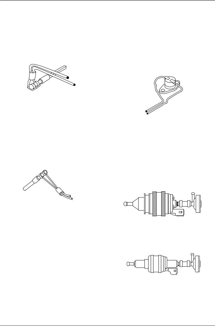
2.8Dosing Pump
The dosing pump is a combined supply, dosing and shutoff system for the fuel supply of the heater out of the vehicle’s fuel tank.
Dosing Pump DP 2 for Gasoline and Diesel operated Heaters
Dosing Pump DP 30 for Diesel operated Heaters
203

Air Top 2000 S |
3 Functional Description |
|
|
3.Functional Description
3.1Functional Description Air Top 2000 S
3.1.1Control Element
The control element is used to switch the air heater on and off, set the desired room temperature (air intake temperature between 10 °C and 45 °C), and to unlock a failure interrupt condition.
The green LED indication is used to indicate the operating condition (LED permanently on) and an overheat condition (LED flashes).
3.1.2 Switch-On
The control element is set to the desired room temperature. When switching the air heater on, the operating indicator is illuminated and the glow plug is activated (cycled). The motor of the combustion and heating air fan starts high-speed operation for 1 second (breakaway moment) and is then under slow-down control to approx. 30% (Diesel) or 50% (fuel) of full speed.
NOTE
Should the temperature of the intake air be above the selected, rated temperature, only the motor of the combustion and heating air fan will operate (control idle). Start operation will be initiated with a heating air temperature below the rated temperature.
The flame sensor function is checked. If the flame sensor at this time already signals “flame”, there will be a 120 second run-down and an error lockout of the control unit. A malfunction of any other component monitored causes an error lockout without run-down.
After approx. 20 seconds (for fuel operated heaters after approx. 15 seconds) the fuel dosing pump is activated. After another 25 seconds the speed of the combustion and heating air fan is continuously increased to a higher rate and combustion begins. As soon as a flame is detected, combustion will be stabilized (see 3.1.3).
Should no normal combustion be achieved within 120 seconds (for fuel operated heaters after approx. 115 seconds), the speed of the combustion and heating air fan is increased for approx. 30 sec and there will be an automatic repeat start with the glow plug activated and fuel dosing pump deactivated (no fuel supply).
Should no proper combustion develop within 120 seconds (for fuel-operated within 115 seconds) the combustion and heating air fan speed is increased to full load for approx. 30 seconds (15 seconds for fuel-operated heaters) with the glow plug on and the dosing pump off (no fuel delivery) with a subsequent automatic restart.
Should the no-combustion-condition persist, after another 80 seconds (for fuel operated heaters after approx. 85 seconds) there will be a switch-off by error lockout (see 3.1.8) with a run-down of the combustion and heating air fan lasting 120 seconds at 2/3 of its max. speed.
2. Start (automatic restart)
Fan speed is again reduced to approx. 30% (for fuel operated heaters to approx. 50%) and fuel is delivered. During the next 20 seconds fan speed is increased to approx. 60% (for fuel-operated heaters to approx. 75%) of full speed. As soon as a flame is detected within the next 55 seconds, combustion will be stabilized. Should there be no flame condition after a total fuel delivery period of 180 seconds, fuel delivery will be stopped and the glow plug deactivated. The combustion air fan continues full load operation for another 120 seconds (run-down) and the heater enters the error lockout condition.
3.1.3 Stabilization
Diesel Operated Heaters
With the glow plug activated the operating speed of the combustion and heating air fan is increased. After another 20 seconds the speed of the combustion and heating air fan is continuously increased within 17 seconds to full load for full heat.
NOTE
This operating condition is omitted if the set temperature (control idle) has already been achieved once.
The glow plug is deactivated and heating operation commences. A flame-out during speed up control causes a restart, 5 restarts an error lockout of the heater.
Fuel Operated Heaters
With the glow plug activated the operating speed of the combustion and heating air fan is continuously increased within 4 seconds to full load for full heat. This operating condition will be omitted if the start occurs after a control idle period.
The glow plug is deactivated and heating operation commences. A flame-out during speed up control causes a restart, 5 restarts an error lockout of the heater.
301

3 Functional Description |
Air Top 2000 S |
|
|
3.1.4 Heating Operation
During operation the combustion exhaust gasses flow through the heat exchanger charging its walls with combustion heat, which in turn is taken up by the heating air delivered by the heating air fan to be routed to the vehicle interior.
The temperature of the heating air sucked in is measured by means of a temperature sensor fitted to the air intake side of the air heater or by means of an externally located temperature sensor.
A temperature below the one set with the control element increases the heater performance up to maximum heat. In order to extend the burner idle period of Diesel operated heaters during permanent operation with a heating performance in excess of 1.1 kW, the fuel dosing pump delivery rate is reduced every 15 minutes for 20 seconds.
A heating performance less than 1.1 kW causes the fuel delivery to the dosing pump to be interrupted every 30 minutes for 4 seconds. Additionaly heating operation is briefly suspended every 9 hours like in control idle. For Diesel-operated heaters this is only applicable, if at this time heating performance is less than 1.1 kW.
3.1.5 Control Operation
During control operation fan speed and dosing pump rate of delivery are subject to heating performance. The glow plug is deactivated.
3.1.6 Control Idle
After reaching the temperature set with the control element, heating performance is controlled to decrease. The speed of the combustion and heating air fan slows down and the fuel delivery rate to the dosing pump is reduced. When exceeding the air intake temperature set with the control element during minimum heating performance, the dosing pump is deactivated after 5 seconds and combustion terminates.
Fan speed remains constant for 35 seconds and is then increased to approx. 60% of full speed for cooling the heater down. the fan then continues to operate at approx. 30% of full speed until temperature is below the temperature set with the control element. If temperature falls below the one set with the control element, the heater will restart (without break away).
NOTE
New settings on the control element are executed by the control unit/heater with a time delay.
3.1.7 Switch-Off
Switching the heater off extinguishes the operation indication of the control element.
If no fuel has been delivered or if the air heater is in control idle, the air heater is deactivated immediately without run-down.
If fuel supply has commenced it will be immediately stopped at switch-off. Fan speed remains constant and then decreases within 30 seconds to approx. 60% of full speed. After this or with the flame sensor detecting “no flame”, fan speed rises to maximum speed for 60 seconds and run down for 120 seconds is initiated. Rundown is at approx. 60% of full speed and is deactivated automatically.
NOTE
Re-activation of the heater during run-down is permitted. Run-down will be completed first with a subsequent restart.
3.1.8 Switch-off upon Failure
The control unit recognizes failures of individual air heater components and malfunctions in the start sequence and in normal operation.
The air heater is deactivated and enters the error lock out mode under the following conditions:
flame sensor open or short circuit temperature sensor open or short circuit glow plug open or short circuit
fan motor open or short circuit or fan speed wrong dosing pump open or short circuit
overheating
low voltage below 10 Volt or high voltage above
15 Volt in excess of 20 seconds for 12 Volt heaters low voltage below 20 Volt or high voltage above
30 Volt in excess of 20 seconds for 24 Volt heaters
A switch-off like in “switch-off” will be performed.
In case of overheating there will be no fuel supply. After run-down the control unit is in the error lockout mode. The operation indication outputs a flash code.
For error unlock the air heater has to be switched off momentarily (at least 2 seconds) before switching on.
302

Air Top 2000 S |
4 Technical Data |
|
|
4.Technical Data
As long as no threshold values are given, the following technical data are understood to include tolerances of
±10% usual for heaters at an ambient temperature of +20 °C and at nominal voltage and conditions.
Electrical Components:
Control unit, combustion air fan, dosing pump, timer, glow plug and control dial are for 12 or 24 Volts operation.
The components temperature limiter and flame detector are independent of voltage.
Fuel for Air Top 2000 S B (gasoline):
The fuel specified by the manufacturer must be used.
Fuel for Air Top 2000 S D (diesel/PME):
The diesel fuel specified by the vehicle manufacturer must be used.
We know of no negative influences due to additives.
If fuel is extracted from the vehicle’s tank, follow the additive instructions issued by the vehicle manufacturer.
If you change to low-temperature fuel, the heater must be operated for approx. 15 minutes so that the fuel system is filled with the new fuel.
The Air Top 2000 S D heater is also licensed for use with PME (bio-diesel), which complies with ASTM D6751 and DIN EN 14214.
|
Air Heater |
Operation |
AT 2000 S B |
|
|
|
|
AT 2000 S D |
|||
|
|
|
|
|
|
|
|
|
|
|
|
|
Mark of conformity |
|
~ S 325 |
|
|
|
|
~ S 324 |
|||
|
|
|
|
|
|
|
|
||||
|
Heater type |
|
|
Air heater with evaporator burner |
|
|
|||||
|
|
|
|
|
|
|
|
|
|
|
|
|
Heat flow |
|
Control range |
1.1 – 2.0 kW |
|
|
|
|
0.9 – 2.0 kW |
||
|
|
|
|
|
|
|
|
|
|
|
|
|
Type of fuel |
|
|
Gasoline |
|
|
|
|
Diesel/Fuel oil (EL) |
||
|
|
|
|
|
|
|
|
|
|
||
|
Fuel consumption |
Control range |
0.1 .. 0.2 kg/h (0.16..0.27 l/h) |
|
|
|
0.1 .. 0.21 kg/h (0.12 .. 0.24 l/h) |
||||
|
|
|
|
|
|
|
|
|
|
|
|
|
Nominal voltage |
|
|
12 Volt |
|
|
|
|
12 Volt |
24 Volt |
|
|
|
|
|
|
|
|
|
|
|
||
|
Operation voltage |
|
10 … 15 Volt |
|
|
|
10 … 15 Volt |
20 … 30 Volt |
|||
|
|
|
|
|
|
|
|
||||
|
Rated power consumption |
Control range |
|
9 ...22 W |
|
|
|||||
|
|
|
|
|
|
|
|
|
|
|
|
|
Permitted ambient temp.: |
|
-40 ° … +40 °C |
|
|
||||||
|
Heater: |
- operation |
|
|
|
||||||
|
Dosing pump: |
- storage |
|
-40 |
° |
… +85 |
°C |
|
|
||
|
- operation |
|
-40 |
° |
… +20 |
°C |
|
|
|||
|
Control element: |
- storage |
|
-40 |
° |
… +85 |
°C |
|
|
||
|
- operation |
|
-40 |
° |
… +75 |
°C |
|
|
|||
|
|
- storage |
|
-40 |
° |
… +85 |
°C |
|
|
||
|
Permitted combustion air |
|
-40 ... +20 °C |
|
|
||||||
|
intake temperature |
|
|
|
|||||||
|
Setting range for |
|
Control range |
+10 ... +45 °C |
|
|
|||||
|
indoor temperature |
|
|
||||||||
|
|
|
|
|
|
|
|
|
|
|
|
|
Volume flow of heating air |
Max. |
|
70 m3/h |
|
|
|
||||
|
against 0.5 bar |
|
|
|
|
|
|||||
|
|
|
|
|
|
|
|
|
|
|
|
|
CO2 in exhaust |
|
Max. |
9.5 … 10.5 |
|
|
|
|
9.5 … 12.0 |
||
|
(perm. functional range) |
|
|
|
|
||||||
|
|
|
|
|
|
|
|
|
|
||
|
Dimensions air heater |
|
Length 311 ± 2 mm |
|
|
||||||
|
|
|
|
Width |
|
120 |
± |
1 mm |
|
|
|
|
|
|
|
Height 121 |
± |
1 mm |
|
|
|||
|
Weight, heater |
|
|
|
|
2.6 kg |
|
|
|
||
|
|
|
|
|
|
|
|
|
|
|
|
|
|
|
|
|
|
|
|
|
|
|
|
401
 Loading...