

Webasto Air Top Evo 40B, Air Top Evo 55D, Air Top Evo 40D, Air Top Evo 55B Installation Instructions
Page 1

Luftheizgeräte
Air heaters
Einbauanweisung
Installation Instructions
Air Top Evo 40
Air Top Evo 55
Handelsbezeichnungen /Trade names :
Air Top Evo 40 B (Benzin) (petrol)
Air Top Evo 40 D (Diesel/PME)
Air Top Evo 55 B (Benzin) (petrol)
Air Top Evo 55 D (Diesel/PME)
Page 2

Page 3
Das unsachgemäße Einbauen oder Reparieren von Webasto Heiz- und Kühlsystemen kann Feuer verursachen oder
zum Austritt von tödlichem Kohlenmonoxid führen. Dadurch können schwere oder tödliche Verletzungen
hervorgerufen werden.
Für den Einbau und die Reparatur von Webasto Heiz- und Kühlsystemen bedarf es eines Webastotrainings,
technischer Dokumentation, Spezialwerkzeuge und einer Spezialausrüstung.
Es dürfen nur Originalteile von Webasto verwendet werden. Siehe dazu auch Zubehörkatalog Luft- und
Wasserheizgeräte von Webasto.
Versuchen Sie NIEMALS, Webasto Heiz- oder Kühlsysteme einzubauen oder zu reparieren, wenn Sie das
Webastotraining nicht erfolgreich abgeschlossen und dabei die notwendigen technischen Fähigkeiten erworben
haben und die für einen sachgerechten Einbau und Reparatur nötigen technischen Dokumentationen, Werkzeuge
und Ausrüstungen nicht zur Verfügung stehen.
Befolgen Sie IMMER alle Webasto Einbau- und Reparaturanleitungen, und beachten Sie alle Warnhinweise.
Webasto übernimmt keine Haftung für Mängel und Schäden, die auf einen Einbau durch ungeschultes Personal
zurückzuführen sind.
Page 4
Improper installation or repair of Webasto heating and cooling systems can cause fire or the leakage of deadly
carbon monoxide leading to serious injury or death.
To install and repair Webasto heating and cooling systems you need to have completed a Webasto training
course and have the appropriate technical documentation, special tools and special equipment.
Only genuine Webasto parts may be used. See also Webasto air and water heaters accessories catalogue.
NEVER try to install or repair Webasto heating or cooling systems if you have not completed a Webasto
training course, you do not have the necessary technical skills and you do not have the technical
documentation, tools and equipment available to ensure that you can complete the installation and repair
work properly.
ALWAYS carefully follow Webasto installation and repair instructions and heed all WARNINGS.
Webasto rejects any liability for problems and damage caused by the system being installed by untrained personnel.
Page 5

Air Top Evo 40 / Air Top Evo 55
I
Inhaltsverzeichnis
1 Erläuterungen zum Dokument . . . . . . . . . . . . . . . . . . . . . . 1
2 Bestimmungen für den Einbau . . . . . . . . . . . . . . . . . . . . . . 2
3 Verwendung / Ausführung . . . . . . . . . . . . . . . . . . . . . . . . . 4
4 Heizgerät . . . . . . . . . . . . . . . . . . . . . . . . . . . . . . . . . . . . . . 5
5 Kalt- und Warmluft . . . . . . . . . . . . . . . . . . . . . . . . . . . . . . 12
6 Brennstoffversorgung . . . . . . . . . . . . . . . . . . . . . . . . . . . . 15
7 Brennluftversorgung . . . . . . . . . . . . . . . . . . . . . . . . . . . . . 22
8 Abgasanlage . . . . . . . . . . . . . . . . . . . . . . . . . . . . . . . . . . . 25
9 Elektrische Anschlüsse . . . . . . . . . . . . . . . . . . . . . . . . . . . 28
10 Schaltpläne . . . . . . . . . . . . . . . . . . . . . . . . . . . . . . . . . . . . 34
11 Erstinbetriebnahme. . . . . . . . . . . . . . . . . . . . . . . . . . . . . . 43
12 Störungen . . . . . . . . . . . . . . . . . . . . . . . . . . . . . . . . . . . . . 43
13 Technische Daten . . . . . . . . . . . . . . . . . . . . . . . . . . . . . . . 44
14 Bohrschablonen . . . . . . . . . . . . . . . . . . . . . . . . . . . . . . . . 46
Table of Contents
1 Explanatory Notes on Document . . . . . . . . . . . . . . . . . . . .49
2 Regulations governing installation . . . . . . . . . . . . . . . . . . .50
3 Use / version. . . . . . . . . . . . . . . . . . . . . . . . . . . . . . . . . . . .52
4 Heater . . . . . . . . . . . . . . . . . . . . . . . . . . . . . . . . . . . . . . . .53
5 Cold air and hot air . . . . . . . . . . . . . . . . . . . . . . . . . . . . . .60
6 Fuel supply . . . . . . . . . . . . . . . . . . . . . . . . . . . . . . . . . . . . .63
7 Combustion air supply . . . . . . . . . . . . . . . . . . . . . . . . . . . .70
8 Exhaust system . . . . . . . . . . . . . . . . . . . . . . . . . . . . . . . . . 73
9 Electrical connections. . . . . . . . . . . . . . . . . . . . . . . . . . . . .76
10 Wiring diagrams. . . . . . . . . . . . . . . . . . . . . . . . . . . . . . . . .82
11 Initial start-up . . . . . . . . . . . . . . . . . . . . . . . . . . . . . . . . . .91
12 Faults . . . . . . . . . . . . . . . . . . . . . . . . . . . . . . . . . . . . . . . . .91
13 Technical Data . . . . . . . . . . . . . . . . . . . . . . . . . . . . . . . . . .92
14 Drilling templates . . . . . . . . . . . . . . . . . . . . . . . . . . . . . . .94
Page 6
1
Air Top Evo 40 / Air Top Evo 55
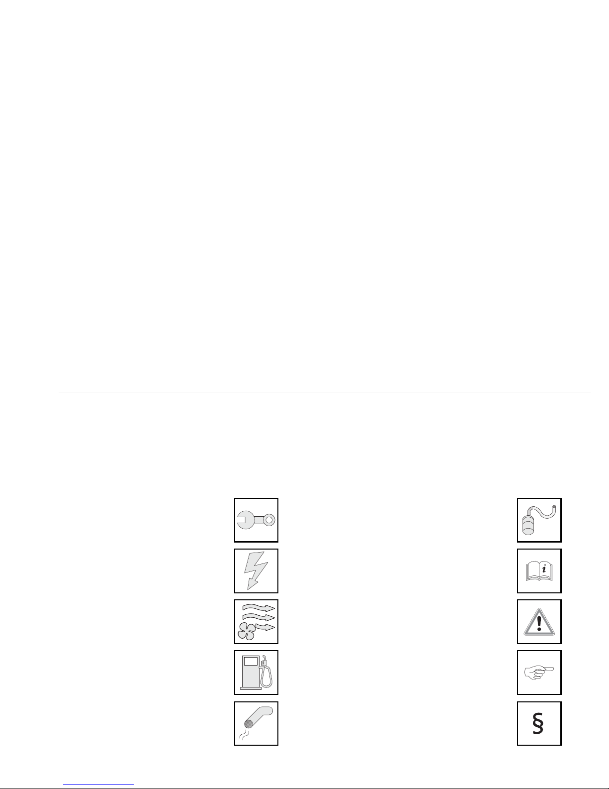
Hinweis
Mechanik
Elektrik
Erwärmte Luft
Brennstoff
Abgas
Brennluft
Achtung
Technische Information
Auszug Richtlinie
1 Erläuterungen zum Dokument
Um Ihnen einen schnellen Überblick über die einzelnen Arbeitsschritte zu geben, finden Sie eine Kennzeichnung an der Außenkante oben auf der jeweiligen
Seite.
Abschnitte, die kursiv dargestellt sind, enthalten den Auszug aus der Richtlinie ECE-R 122.
Page 7

Technische Information Air Top Evo 40 / Air Top Evo 55
2
2 Bestimmungen für den Einbau
2.1. Gesetzliche Bestimmungen für den Einbau
Für die Heizgeräte Air Top Evo 40 / Air Top Evo 55 bestehen
Typgenehmigungen nach ECE-R 10 (EMV) und ECE-R 122 (Heizungen).
Genehmigungsnummern siehe Kapitel 13, "Technische Daten".
Für den Einbau sind in erster Linie Teil I und Anhang 7 der Richtlinie ECER 122 zu beachten.
2.2. Applikation von Verbrennungsheizgeräten in Fahrzeuge zur
Beförderung gefährlicher Güter (ADR)
Fahrzeuge mit dem Zweck der Beförderung von gefährlichen Gütern werden
nach der ECE-R 105 typgeprüft. Folgende Maßnahmen sind für unsere
Verbrennungsheizgeräte abgeleitet:
Die elektrische Leitung/der Kabelbaum muss ausreichend bemessen sein,
damit Überhitzungen vermieden werden. Die elektrische Leitung/der
Kabelbaum muss ausreichend isoliert sein. Alle Stromkreise müssen durch
Sicherungen oder selbsttätige Stromunterbrecher geschützt sein.
Die Kabel müssen sicher befestigt und so verlegt sein, dass die Leitungen
ausreichend gegen mechanische und thermische Beanspruchung
geschützt sind.
Die Verbrennungsheizgeräte müssen nach der ECE-R 122 typgeprüft sein
und den Anhang 9 – Zusätzliche Vorschriften für Fahrzeuge zur
Beförderung gefährlicher Güter erfüllen.
Verbrennungsheizgeräte und Ihre Abgasleitungen müssen so konzipiert,
angeordnet, geschützt oder abgedeckt sein, dass jedes inakzeptable
Risiko einer Erhitzung oder Entzündung der Ladung vermieden wird.
Im Falle einer Leckage der Brennstoffleitung muss der Brennstoff auf den
Boden abgeleitet werden, ohne dass er mit heißen Teilen des Fahrzeugs
oder mit der Ladung in Berührung kommt.
Das Abgassystem und die Abgasleitungen müssen so angeordnet oder
geschützt sein, dass es nicht zu einer gefährlichen Erhitzung oder
Entzündung der Ladung kommen kann. Direkt unter dem
Brennstoffbehälter liegende Teile des Abgassystems müssen in einem
Abstand von 100 mm dazu angeordnet oder durch einen Hitzeschild
geschützt sein.
Das Verbrennungsheizgerät darf nur von Hand eingeschaltet werden.
Automatisches Einschalten über einen programmierbaren Schalter ist
nicht zulässig. Das Verbrennungsheizgerät darf nach Abstellen des
Fahrzeugmotors von Hand wieder eingeschaltet werden.
HINWEIS:
Die Bestimmungen dieser Richtlinien sind im Geltungsbereich
der EU-Richtlinie 70/156/EWG und/oder EG/2007/46 (für
neue Fahrzeugtypen ab 29.04.2009) bindend und sollten in
Ländern, in denen es keine speziellen Vorschriften gibt,
ebenfalls beachtet werden!
HINWEIS:
Die Nichtbeachtung der Einbauanweisung führt zum
Erlöschen der Typgenehmigung des Heizgeräts und damit der
allgemeinen Betriebserlaubnis des Fahrzeugs.
HINWEIS:
Bei Fahrzeugen mit einer EU-Typgenehmigung ist ein Eintrag
nach § 19 Abschnitt 4 des Anhangs VIII b zur StVZO nicht
erforderlich.
Landesspezifische Zulassungsverordnungen sind einzuhalten.
Page 8

Air Top Evo 40 / Air Top Evo 55 Technische Information
3
Anforderung an das Grundgerät:
Ein Nachlauf von maximal 40 Sekunden ist bei einem abgeschalteten
Verbrennungsheizgerät erlaubt. Es dürfen nur Verbrennungsheizgeräte
verwendet werden, deren Wärmeübertrager durch die verringerte
Nachlaufzeit von 40 Sekunden über ihre übliche Benutzungsdauer nicht
nachweislich geschädigt werden.
2.3. Zusätzlich zu verwendende Dokumentation
Diese Einbauanweisung enthält alle notwendigen
Informationen und Anweisungen bzgl. des Einbaus von
Heizgeräten Air Top Evo 40 / Air Top Evo 55.
Zusätzlich muss die Bedienungsanweisung beachtet werden.
Page 9

Technische Information Air Top Evo 40 / Air Top Evo 55
4
3 Verwendung / Ausführung
3.1. Verwendung
Die Luftheizgeräte Webasto Air Top Evo 40 und Air Top Evo 55 eignen sich
zum
Beheizen von Kabinen, Booten, Lkws, Kleinbussen, Transportern,
Ambulanzfahrzeugen und Reisemobilen
Entfrosten der Fahrzeugscheiben
Beheizen von Ladegut
Die Heizgeräte arbeiten unabhängig vom Fahrzeugmotor. Sie werden an den
Brennstoffbehälter und an die elektrische Anlage des Fahrzeugs
angeschlossen.
Eine Verwendung für Fahrzeuge mit wasser- oder luftgekühltem Motor ist
möglich.
Sie sind nicht zur Beheizung des Gefahrgut-Transportraums zugelassen.
3.2. Ausführung
Luftheizgerät für Brennstoff “Benzin” (12 Volt):
Air Top Evo 40 B (Benzin)
Air Top Evo 55 B (Benzin)
Luftheizgerät für Brennstoff “Diesel” (12 oder 24 Volt):
Air Top Evo 40 D (Diesel)
Air Top Evo 55 D (Diesel)
Page 10
Air Top Evo 40 / Air Top Evo 55 Technische Information
5
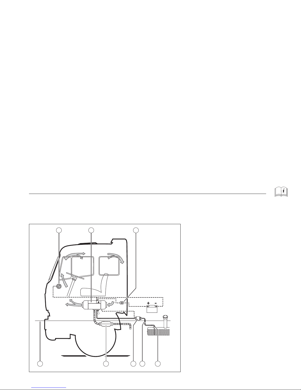
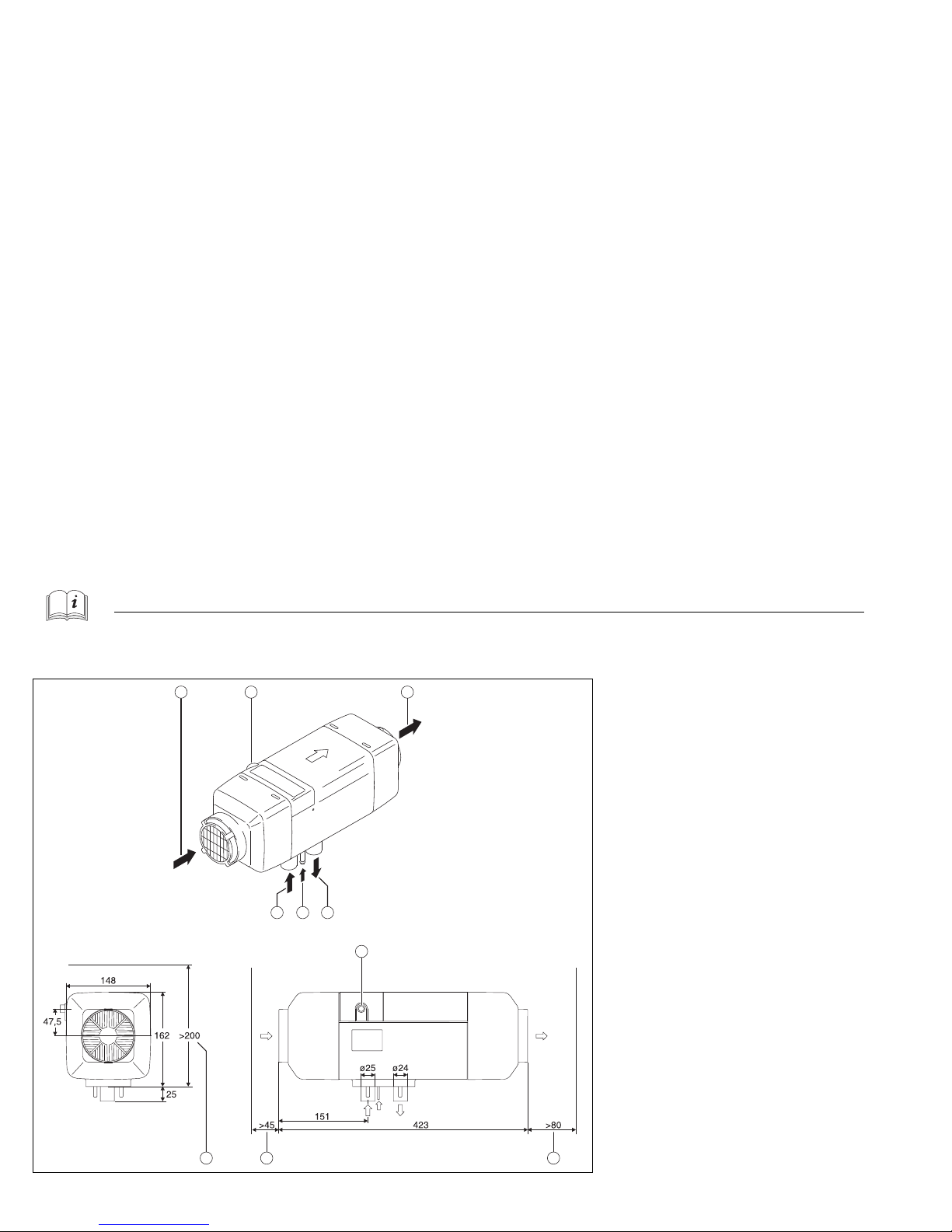
4Heizgerät
Die Einbaugegebenheiten hängen vom Fahrzeugtyp ab.
1)
Bedienelement
2) Heizgerät
3) Sicherung
4) Tankentnehmer
5) Brennstofffilter (optional)
6) Brennstoffpumpe
7) Abgasschalldämpfer (optional)
8) Maximal zulässige Wasserdurchfahrtshöhe
Abb. 1 Einbaubeispiel
1
78 6 5 4
2 3
Page 11

Technische Information Air Top Evo 40 / Air Top Evo 55
6
4.1. Anforderungen an Einbauort Nur für ADR:
Teile des Aufbaus und andere Bauteile in der Nähe des Heizgeräts müssen vor übermäßiger Erwärmung und einer möglichen Verschmutzung durch Brennstoff oder Öl geschützt
sein.
(Forderung aus ECE-R 122, Punkt 5.3.2.1.).
Vom Heizgerät darf auch bei Überhitzung keine Brandgefahr
ausgehen. Diese Vorschrift gilt als eingehalten, wenn beim
Einbau ein entsprechender Abstand zu allen Teilen
eingehalten und für ausreichende Belüftung gesorgt wurde
oder feuerbeständige Werkstoffe oder Hitzeschilde verwendet wurden.
(Forderung aus ECE-R 122, Punkt 5.3.2.2.).
Bei Fahrzeugen der Klassen M2 und M3 darf sich das Verbrennungsheizgerät nicht im Fahrgastraum befinden. Seine
Anbringung im Fahrgastraum ist jedoch zulässig, wenn es
sich in einem wirksam abgedichteten Gehäuse befindet, das
ebenfalls den Vorschriften des Absatzes 5.3.2.2 entspricht.
(Forderung aus ECE-R 122, Punkt 5.3.2.3.).
Der Einbauort des Heizgeräts ist so zu wählen, dass die
Gefahr der Verletzung von Personen und der Beschädigung
von mitgeführten Gegenständen so gering wie möglich ist.
(Forderung aus ECE-R 122, Punkt 5.3.2.5.).
Fahrzeuge EX/II, EX/III, AT, FL, und OX:
Verbrennungsheizgeräte und ihre Abgasleitungen müssen so
konstruiert, angeordnet, geschützt oder abgedeckt sein, so
dass jedes unakzeptable Risiko einer Erhitzung oder Entzündung der Ladung vermieden wird. Diese Vorschrift gilt als
eingehalten, wenn der Brennstoffbehälter und das Abgassystem des Geräts folgenden Bestimmungen entsprechen:
- Jeder Brennstoffbehälter zur Versorgung des Heizgeräts muss folgenden Vorschriften entsprechen:
a) Im Falle einer Leckage muss der Brennstoff auf
den Boden abgeleitet werden, ohne dass er mit
heißen Teilen des Fahrzeugs oder mit der Ladung
in Berührung kommt;
[...]
- Das Abgassystem und die Abgasleitungen müssen so
angeordnet oder geschützt sein, dass es nicht zu einer
gefährlichen Erhitzung oder zur Entzündung der
Ladung kommen kann. Direkt unter dem Kraftstoffbehälter (Dieselkraftstoff) liegende Teile des
Abgassystems müssen in einem Abstand von mindestens 100 mm dazu angeordnet oder durch einen Hitzeschild geschützt sein.
Die Einhaltung dieser Vorschriften ist am vollständigen Fahrzeug zu überprüfen.
(Forderung aus ECE-R 122, Anhang 9, Punkt 3.1.1).
Page 12

Air Top Evo 40 / Air Top Evo 55 Technische Information
7
Das Heizgerät kann im Außenbereich und im Innenraum eingebaut werden.
Außenbereich
Heizgerät nur an einem von Spritzwasser und Gischt geschützten Bereich
einbauen.
Heizgerät so einbauen, dass bei einer Wasserdurchfahrt kein Wasser ins
Heizgerät eindringen kann.
Fußdichtung einlegen zwischen Heizgerät und Auflagefläche.
Die maximal zulässige Wasserdurchfahrtshöhe (Wattiefe) ist vom Fahrzeug
abhängig (siehe Abb. 1).
Innenraum
Fußdichtung einlegen zwischen Heizgerät und Auflagefläche.
Fahrzeuge FL:
Verbrennungsheizgeräte müssen mindestens durch die nachstehend beschriebenen Verfahren außer Betrieb gesetzt werden können:
a) Abschaltung von Hand im Fahrerhaus;
b) Abstellen des Fahrzeugmotors; in diesem Fall darf
das Heizgerät vom Fahrzeugführer von Hand wieder
eingeschaltet werden;
c) Inbetriebnahme einer eingebauten Förderpumpe im
Kraftfahrzeug für beförderte gefährliche Güter.
[...]
(Forderung aus ECE-R 122, Anhang 9, Punkt 3.3.1).
HINWEIS:
Befindet sich das Heizgerät in Reichweite des Fahrers, ist das
Heizgerät nur mit Berührschutz einzubauen.
Page 13
Technische Information Air Top Evo 40 / Air Top Evo 55
8
4.2. Heizgerät einbauen
1)
Kaltlufteinlass
2) Kabelabgang (wahlweise rechts oder links)
3) Warmluftauslass
4) Abgasauslass
5) Brennstoffeinlass
6) Brennlufteinlass
A) Raumbedarf Warmluftauslass
B) Raumbedarf Kaltlufteinlass
C) Raumbedarf Ausbau des Heizgeräts
Abb. 2 Abmessungen und Raumbedarf [mm]
1
6 5 4
2 3
B AC
2
Page 14
Air Top Evo 40 / Air Top Evo 55 Technische Information
9
Raumbedarf und Einbauposition ermitteln (siehe Abb. 2, Abb. 4 und Abb.
5).
Neigungswinkel einhalten (siehe Abb. 4 und Abb. 5).
Bei größeren Unebenheiten Auflagefläche plan ziehen.
Mithilfe der Bohrschablone (siehe Abb. 39) die Befestigungsbohrungen
und Durchbrüche bohren.
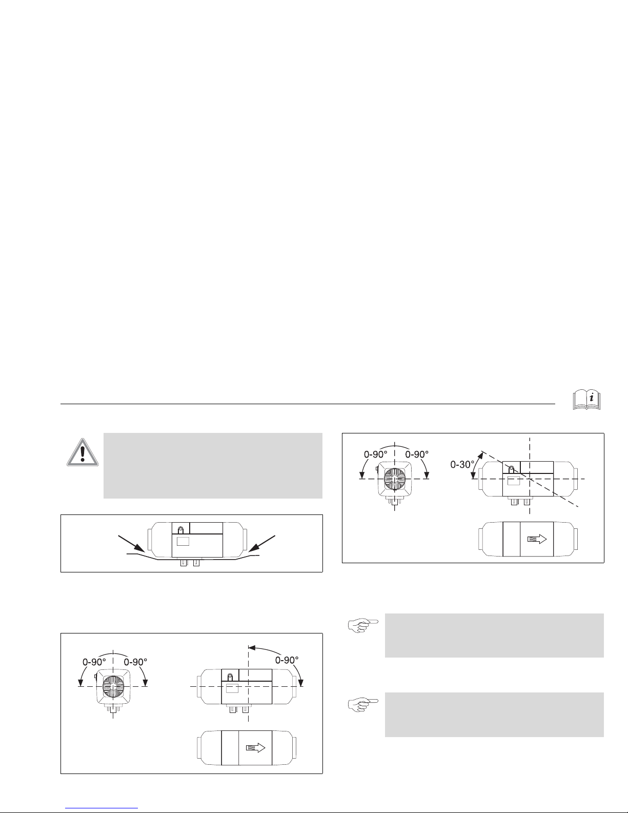
ACHTUNG:
Überhitzung des Heizgeräts durch Blockade des
Heizluftläufers!
Beschädigung des Heizgeräts
Sicherstellen, dass das Gehäuse des Heizgeräts in der
Einbauposition an keiner Stelle anliegt (siehe Abb. 3).
Abb. 3 Nach dem Einbau darf das Gehäuse nirgendwo anliegen.
Abb. 4 Zulässige Einbaulagen Dieselheizgeräte
Abb. 5 Zulässige Einbaulagen Benzinheizgeräte
HINWEIS:
Die Auflagefläche für den Heizgerätefuß muss plan sein. Mit
der Fußdichtung werden Unebenheiten von max. 1 mm
ausgeglichen.
HINWEIS:
Zum Bohren der Durchbrüche und zum Planziehen der
Auflagefläche gibt es ein Sonderwerkzeug (erhältlich über
Webasto).
Page 15
Technische Information Air Top Evo 40 / Air Top Evo 55
10
Fußdichtung anbringen.
Am Typschild alle Jahreszahlen bis auf das Einbaujahr entfernen.
Heizgerät befestigen. Dabei die Muttern M6 mit 6 Nm (–0 Nm, +1 Nm)
festziehen.
Falls das Typschild nach dem Einbau des Heizgeräts nicht gut sichtbar ist,
Typschildduplikat verwenden.
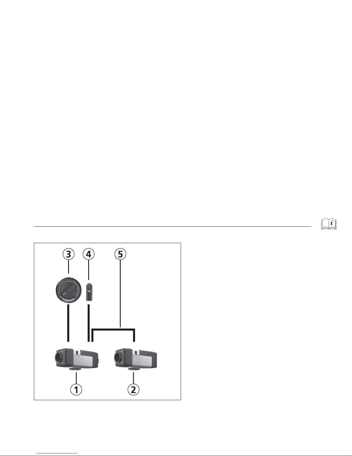
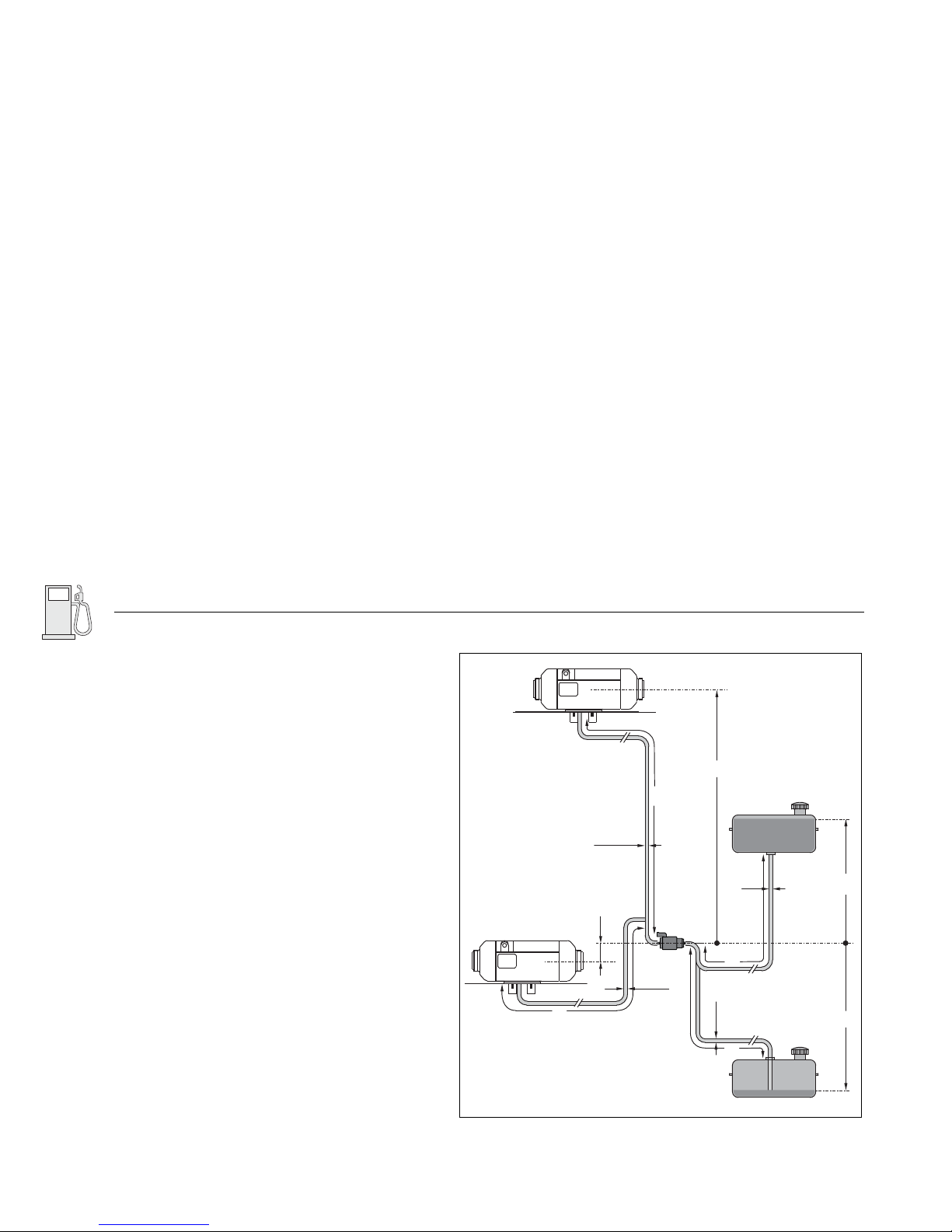
4.3. Aufbau als Air Top Evo System
Die Air Top Evo 40 und Air Top Evo 55 Heizgeräte (Diesel) können als System
mit 2 Heizgeräten aufgebaut werden.
Dabei ist das Gerät 1 als Master Heizgerät definiert und das Gerät 2 als Slave
Heizgerät. An das Master Heizgerät wird das Bedienelement (siehe
Schaltplan Abb. 37) sowie ein externer Temperatursensor (T) angeschlossen.
Das Slave Heizgerät wird entsprechend Schaltplan (siehe Abb. 38)
angeschlossen. Die Geräte kommunizieren untereinander über ein serielles
Bussystem.
ACHTUNG:
Bei Ausbau und erneutem Einbau eines Heizgeräts muss die
Fußdichtung erneuert werden.
Das in Anhang 7 Absatz 4 genannte Schild oder eine
Zweitausfertigung muss so angebracht sein, dass es/sie noch
leicht lesbar ist, wenn das Heizgerät in das Fahrzeug
eingebaut ist.
(Forderung aus ECE-R 122, Punkt 5.3.2.4.).
HINWEIS:
Das Typschild soll nach dem Einbau des Heizgeräts gut
sichtbar sein und an einer geschützten Stelle liegen.
ACHTUNG:
Die Verwendung eines Air Top Evo Systems ist nicht für
Gefahrguttransporte (ADR) zugelassen!
Page 16
Air Top Evo 40 / Air Top Evo 55 Technische Information
11
Abb. 6 Aufbau Air Top System
1) Gerät 1
2) Gerät 2
3) Bedienelement
4) Tem perat urs ens or
5) Bussystem
Page 17
Kalt- und Warmluft Air Top Evo 40 / Air Top Evo 55
12
5Kalt- und Warmluft
5.1. Allgemein
Es ist sowohl Umluft- als auch Frischluftbetrieb zulässig.
Temperaturregelung
Das Steuergerät besitzt einen internen Raumtemperatursensor. Optional
kann auch ein externer Temperatursensor verwendet werden. In
Abhängigkeit von der Ansaugtemperatur und der eingestellten
Solltemperatur regelt die Steuerung das Heizgerät im entsprechenden
Heizleistungsbereich. Die Heizleistung wird so geregelt, dass nach dem
schnellen Erreichen der vorgewählten Kabinentemperatur (Solltemperatur)
diese auf dem vorgewählten Wert gehalten wird.
Frischluftbetrieb
Beim Frischluftbetrieb ist darauf zu achten, dass die Kaltluft aus einem vor
Spritzwasser und Gischt geschützten Bereich entnommen wird. Die
Frischluftansaugung muss oberhalb der für das jeweilige Fahrzeug zulässigen
Wasserdurchfahrtshöhe angebracht werden.
Montage in Einbaukasten
Um Wärmestau und einer daraus folgenden Überhitzung zu vermeiden,
muss gewährleistet sein, dass keine Warmluft direkt in den Einbaukasten
gelangt.
Die Heizluftversorgung kann aus Frischluft oder Umluft bestehen und muss aus einem sauberen Bereich angesaugt werden, der voraussichtlich nicht durch Abgase des Antriebsmotors, des Verbrennungsheizgeräts oder einer anderen Quelle
im Fahrzeug verunreinigt werden kann.
(Forderung aus ECE-R 122, Punkt 5.3.6.1.)
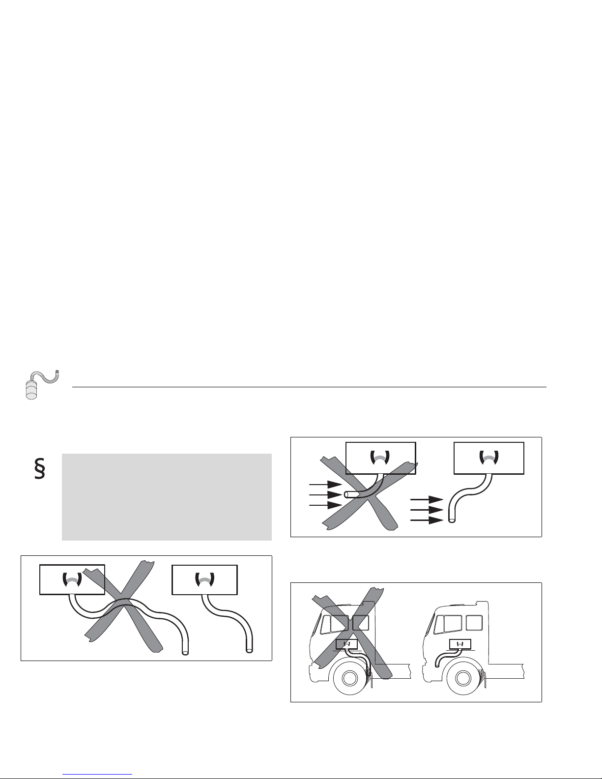
HINWEIS:
Die Einbindung des Heizgeräts in die fahrzeugeigene
Luftführung ist nicht erlaubt.
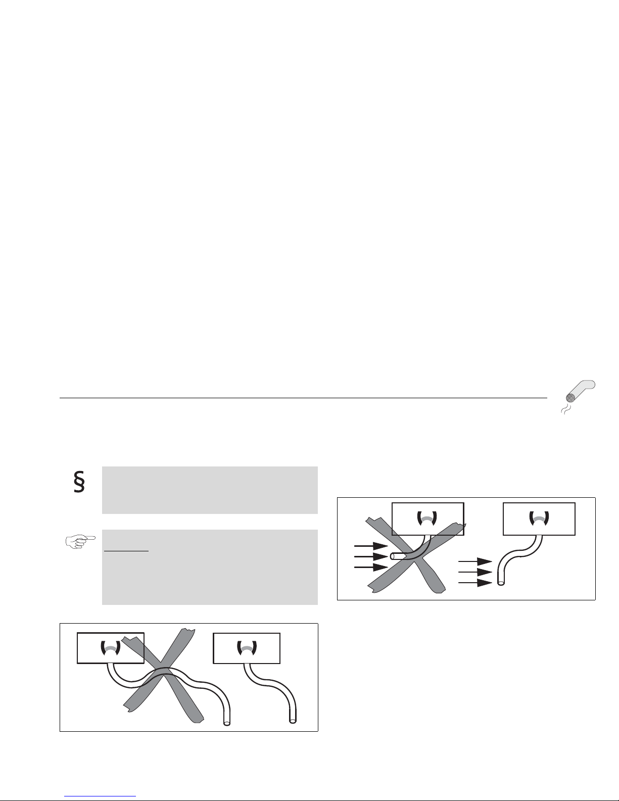
HINWEIS:
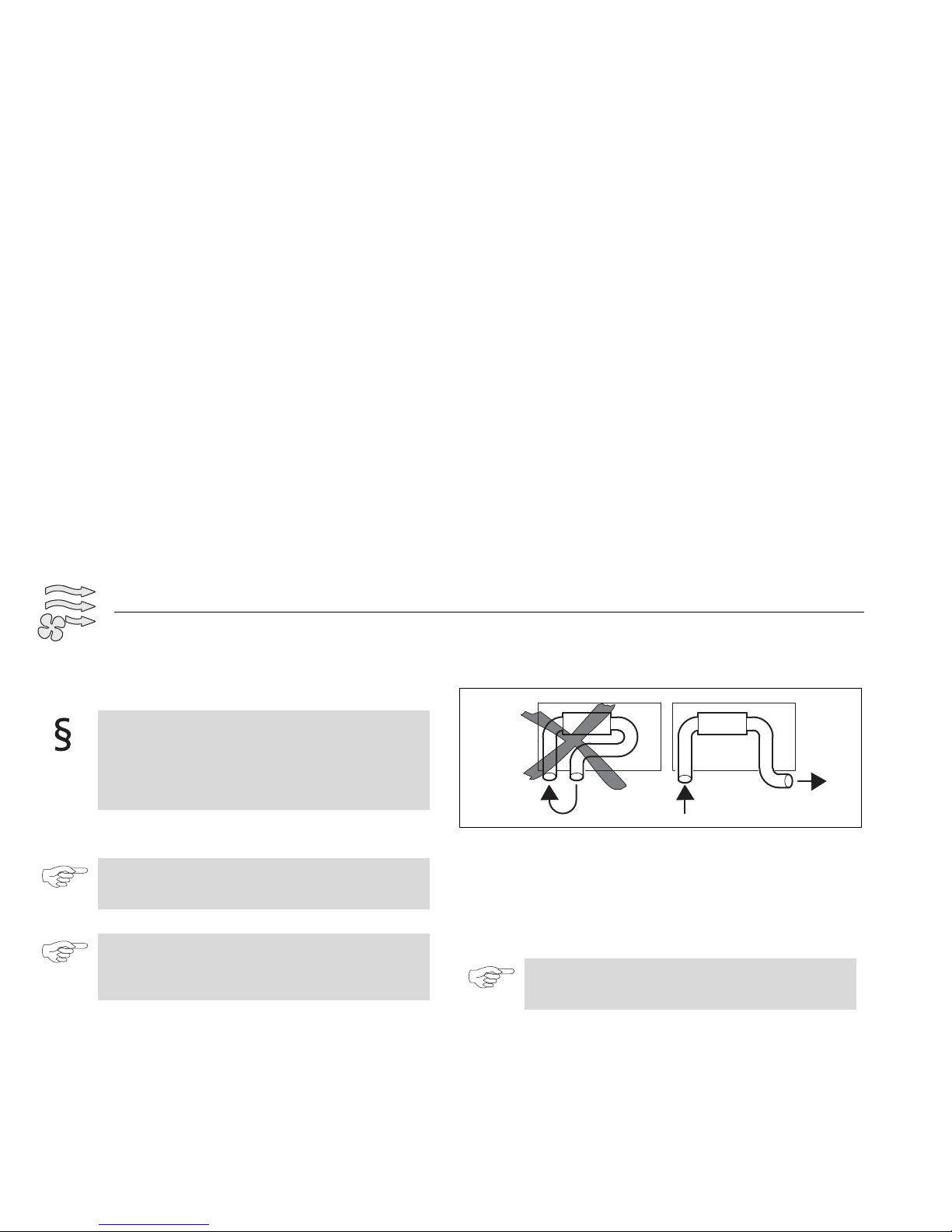
Das direkte Ansaugen der Warmluft muss vermieden werden
(siehe Abb. 7).
Der Kurzschluss des Luftstroms ist nicht erlaubt.
Abb. 7 Kaltlufteinlass und Warmluftauslass
HINWEIS:
Bei Frischluftbetrieb muss ein externer Temperatursensor in
der zu beheizenden Kabine montiert werden.
Page 18
Air Top Evo 40 / Air Top Evo 55 Kalt- und Warmluft
13
Position Öffnungen Warmluft Eigenschaften Kalt- und Warmluftleitung
Empfohlener Innendurchmesser des Hauptstrangs der Warmluftleitung:
90 mm beim Air Top Evo 55
80 mm beim Air Top Evo 40
Anordnung der Kalt- und Warmluftführung
Maximale Druckdifferenz zwischen Saug- und Druckseite des Heizgeräts:
Air Top Evo 40: 2,0 hPa
Air Top Evo 55: 3,0 hPa
Warmluftleitungen innerhalb des Fahrzeugs müssen so angeordnet oder geschützt sein, dass bei Berührung keine Verletzungs- oder Beschädigungsgefahr besteht.
(Forderung aus ECE-R 122, Punkt 5.3.7.1.)
Der Luftauslass muss so angeordnet oder geschützt sein,
dass er nicht durch Müll oder Gepäckstücke blockiert werden
kann.
(Forderung aus ECE-R 122, Punkt 5.3.7.2.)
ACHTUNG:
In Fahrzeugen in denen Personen befördert werden, ist die
Warmluftaustrittsöffnung so auszurichten, dass ein
Mindestabstand von 20 cm zu Körperteilen eingehalten wird.
HINWEIS:
Die Warmluftaustrittsöffnung darf nicht auf
temperaturempfindliche Teile blasen.
HINWEIS:
Bei Ermittlung der Position der Warmluftaustrittsöffnungen
muss auf Folgendes geachtet werden:
Kein Luftkurzschluss zwischen Fahrzeugheizung und
Kaltlufteinlass der Air Top Evo
Kein Luftkurzschluss zwischen Kaltlufteinlass und
Warmluftauslass der Air Top Evo (Abb. 7)
HINWEIS:
Für die Warmluftführung dürfen nur Materialien mit einer
Dauertemperaturfestigkeit von 130 °C (kurzfristig 150 °C)
verwendet werden.
Die Einlassöffnung muss durch Gitter oder andere geeignete
Mittel geschützt sein.
(Forderung aus ECE-R 122, Punkt 5.3.6.2.)
ACHTUNG:
Verwendung ohne Kaltluftansaugschlauch!
Verletzungsgefahr durch den rotierenden Heizluftläufer
Bei Verwendung ohne Kaltluftansaugschlauch das im
Lieferumfang beiliegende Ansauggitter anbauen
ACHTUNG:
Bei Überschreitung dieser Druckdifferenz erfolgt eine Heizleistungsreduzierung.
Page 19

Kalt- und Warmluft Air Top Evo 40 / Air Top Evo 55
14
Einbau der Kalt- und Warmluftführung
Kalt- und Warmluftleitungen an allen Verbindungen sichern.
5.2. Externer Temperatursensor (optional)
Der externe Temperatursensor in der zu beheizenden Kabine einbauen:
auf mittlere Höhe;
an möglichst senkrechten Flächen.
HINWEIS:
Der Temperatursensor sollte nicht
von Warmluft (von fahrzeugeigener Heizung bzw. Air Top
Evo 40 / Air Top Evo 55) direkt angeströmt werden.
in der Nähe von Wärmequellen (z. B. fahrzeugeigene
Heizung) eingebaut werden.
im Bereich direkter Sonneneinstrahlung (z. B.
Armaturenbrett) liegen.
hinter Vorhängen oder Ähnlichem eingebaut werden.
Page 20

Air Top Evo 40 / Air Top Evo 55 Brennstoff
15
6 Brennstoffversorgung
6.1. Allgemein
Der Brennstoff wird dem Brennstoffbehälter des Fahrzeugs, der
Brennstoffleitung des Fahrzeugs oder einem separaten Brennstoffbehälter
entnommen.
6.2. Integration in Vor- oder Rücklaufleitung des Fahrzeugs
Der Brennstoffeinfüllstutzen darf sich nicht im Fahrgastraum
befinden und muss mit einem dicht schließenden Deckel versehen sein, der das Austreten von Brennstoff verhindert.
(Forderung aus ECE-R 122, Punkt 5.3.3.1.).
Bei Heizgeräten für Flüssigbrennstoff, bei denen die Brennstoffversorgung von der Kraftstoffzufuhr des Fahrzeugs
getrennt ist, müssen die Art des Brennstoffs und der Einfüllstutzen deutlich bezeichnet sein.
(Forderung aus ECE-R 122, Punkt 5.3.3.2.).
HINWEIS:
Nur für ADR:
Fahrzeuge EX/II, EX/III, AT, FL und OX: siehe Kapitel 4.1,
"Anforderungen an Einbauort", Auszug aus der Richtlinie.
Die gesetzlichen Bestimmungen der ADR für
Kraftstoffbehälter ECE-R 122, Anhang 9, Punkt 3 sind zu
beachten.
HINWEIS:
– Die Brennstoffentnahme muss nahezu drucklos erfolgen.
– Bei Brennstoffentnahme aus der Rücklaufleitung ist
sicherzustellen, dass diese nicht durch Rückschlagventile
blockiert ist. Weiterhin ist darauf zu achten, dass die
Rücklaufleitung bis zum Tankboden führt.
– Es muss sichergestellt werden, dass durch die
Brennstoffentnahme kein Nullabschluss im
Fahrzeugsystem entsteht.
– Bei Entnahme aus dem Schwalltopf muss sichergestellt
werden, dass dieser nicht vollständig entleert wird.
Page 21
Brennstoff Air Top Evo 40 / Air Top Evo 55
16
6.3. Integration über die fahrzeugeigene Brennstofffördereinheit
Siehe auch Kapitel 4, "Heizgerät" (Abb. 1, "Einbaubeispiel").
Die Nachrüstung der Brennstoffentnahme bei Kunststofftanks erfolgt
ausschließlich durch die Brennstofffördereinheit.
Der Tankentnehmer soll wie in Abb. 9 dargestellt verbaut werden.
Abb. 8 Webasto Brennstoffentnehmer
1) vom Tank
2) zur Brennstoffpumpe
3) zum Motor
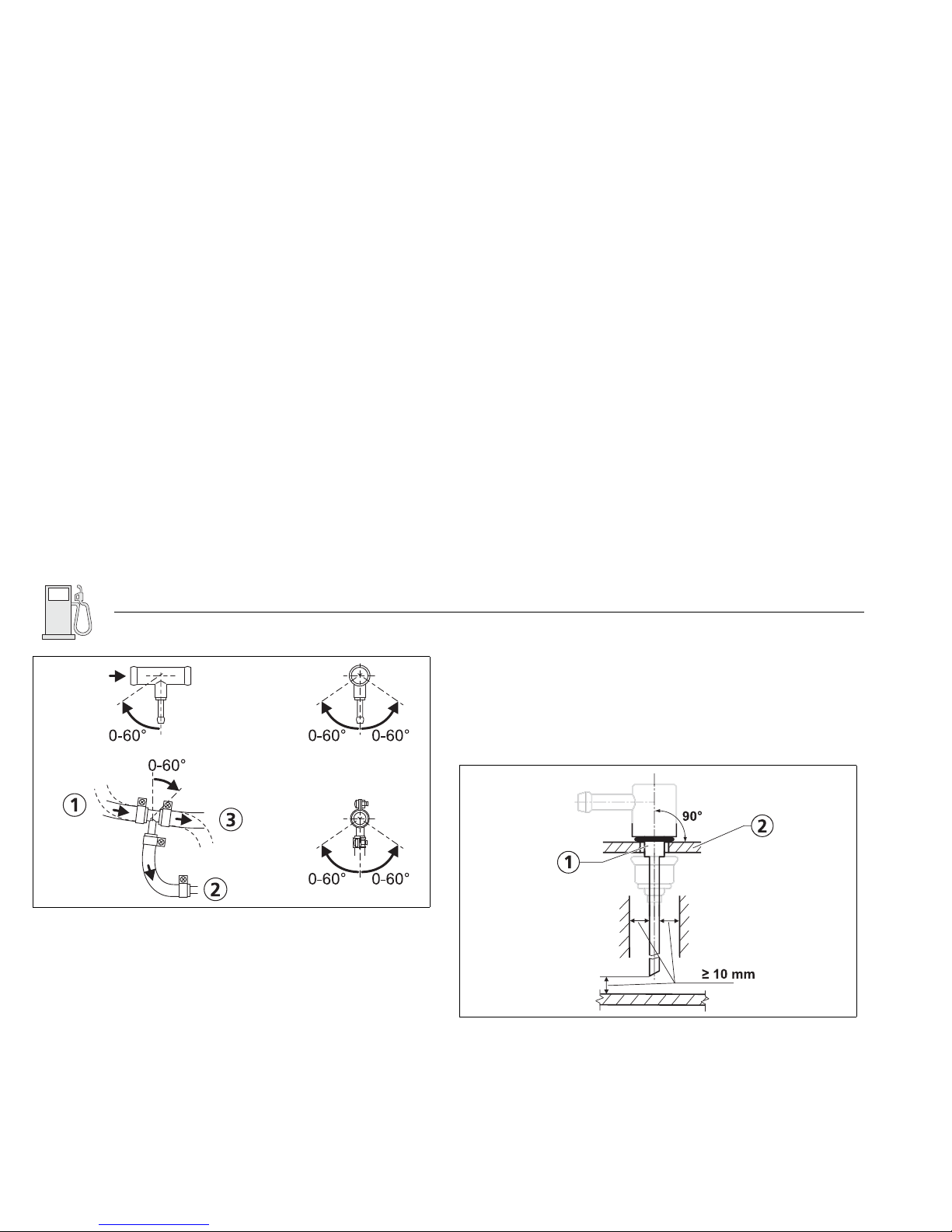
Abb. 9 Webasto Tankentnehmer
1) Webasto Tankentnehmer
2) fahrzeugeigene Brennstofffördereinheit mit Bohrung
Page 22
Air Top Evo 40 / Air Top Evo 55 Brennstoff
17
Die Montagefläche des Tankentnehmers muss sauber, eben und gratfrei sein.
Beim Einsetzen des Tankentnehmers in die Brennstofffördereinheit ist auf
eine sorgfältige Verlegung des Steigrohrs zu achten. Dieses darf in keinem
Betriebszustand die Funktion der Teile der Brennstofffördereinheit inkl.
Füllstandsanzeige beeinträchtigen.
Die Länge des Steigrohrs ist so zu wählen, dass im eingebauten Zustand ein
Mindestabstand von 10 mm über dem Tankboden oder 20 mm über dem
Boden der Brennstofffördereinheit gewährleistet ist.
Die vorgeschriebenen Sicherungsmaßnahmen des Fahrzeugherstellers und
die entsprechenden Drehmomente sind einzuhalten.
6.4. Integration über die Tankablassschraube
Die Brennstoffentnahme kann auch über der Tankablassschraube erfolgen
(siehe Abb. 10).
Mit dieser separaten Brennstoffentnahme wird eine Druckbeeinflussung
ausgeschlossen.
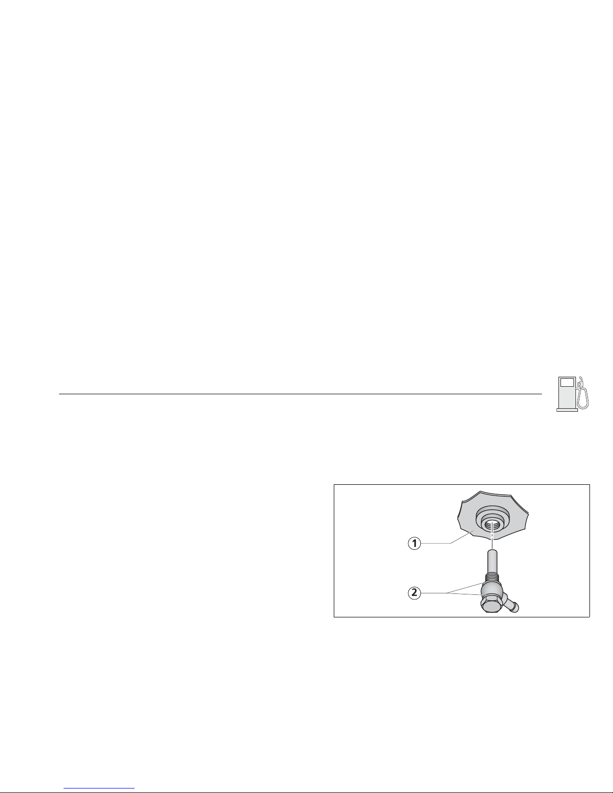
Abb. 10 Brennstoffentnahme aus dem Kunststofftank
(Entnahme über Tankablassschraube)
1) Kunststofftank
2) Dichtring
Page 23
Brennstoff Air Top Evo 40 / Air Top Evo 55
18
6.5. Brennstoffleitungen
Nur Brennstoffleitungen mit einem Innendurchmesser von 2 mm
verwenden.
Die Brennstoffleitung untergliedert sich in Saug- und Druckleitung. Dabei
stellt die Saugleitung eine Verbindung zwischen Tank und Brennstoffpumpe,
die Druckleitung eine Verbindung zwischen Brennstoffpumpe und Heizgerät
her.
6.5.1. Leitungsverlegung
Bei der Verlegung der Brennstoffleitung ist darauf zu achten, diese so kurz
wie möglich zu gestalten.
Siehe Abb. 11.
Die Leitung muss vor Beschädigungen (z. B. Steinschläge) geschützt verlegt
sein.
Die Brennstoffleitung muss in kühlen Bereichen verlegt werden, um
Blasenbildung durch Erwärmung zu vermeiden. Hohe
Brennstofftemperaturen können Fehlfunktionen des Heizgeräts verursachen.
Brennstoffleitungen sind dem Stand der Technik entsprechend zu befestigen.
Die Beschädigung der Brennstoffleitung muss vermieden werden.
Abb. 11 Brennstoffversorgung
H
1
D
1
l
1
l
2
l
2
H
2
l
1
D
2
S
2
D
2
D
1
S
1
Page 24
Air Top Evo 40 / Air Top Evo 55 Brennstoff
19
Saugseite:
D1: Innendurchmesser Brennstoffleitung = 2 mm.
H
1
: Niveau Füllstand (Tank oberhalb Brennstoffpumpe) [m]
S1: Niveau Füllstand (Tank unterhalb Brennstoffpumpe) [m]
l
1
: Länge Brennstoffleitung [m]
Druckseite:
D2: Innendurchmesser Brennstoffleitung = 2 mm.
H
2
: Höhenunterschied Heizgerät - Brennstoffpumpe
(Heizgerät oberhalb Brennstoffpumpe) [m]
S
2
: Höhenunterschied Heizgerät - Brennstoffpumpe
(Heizgerät unterhalb Brennstoffpumpe) [m]
l
2
: Länge Brennstoffleitung [m]
6.5.2. Leitungsausführung
Als Brennstoffleitungen dürfen nur Stahl- und Kunststoffleitungen aus lichtund temperaturstabilem PA11 oder PA12 (z. B. Mecanyl-RWTL) nach
DIN 73378 verwendet werden.
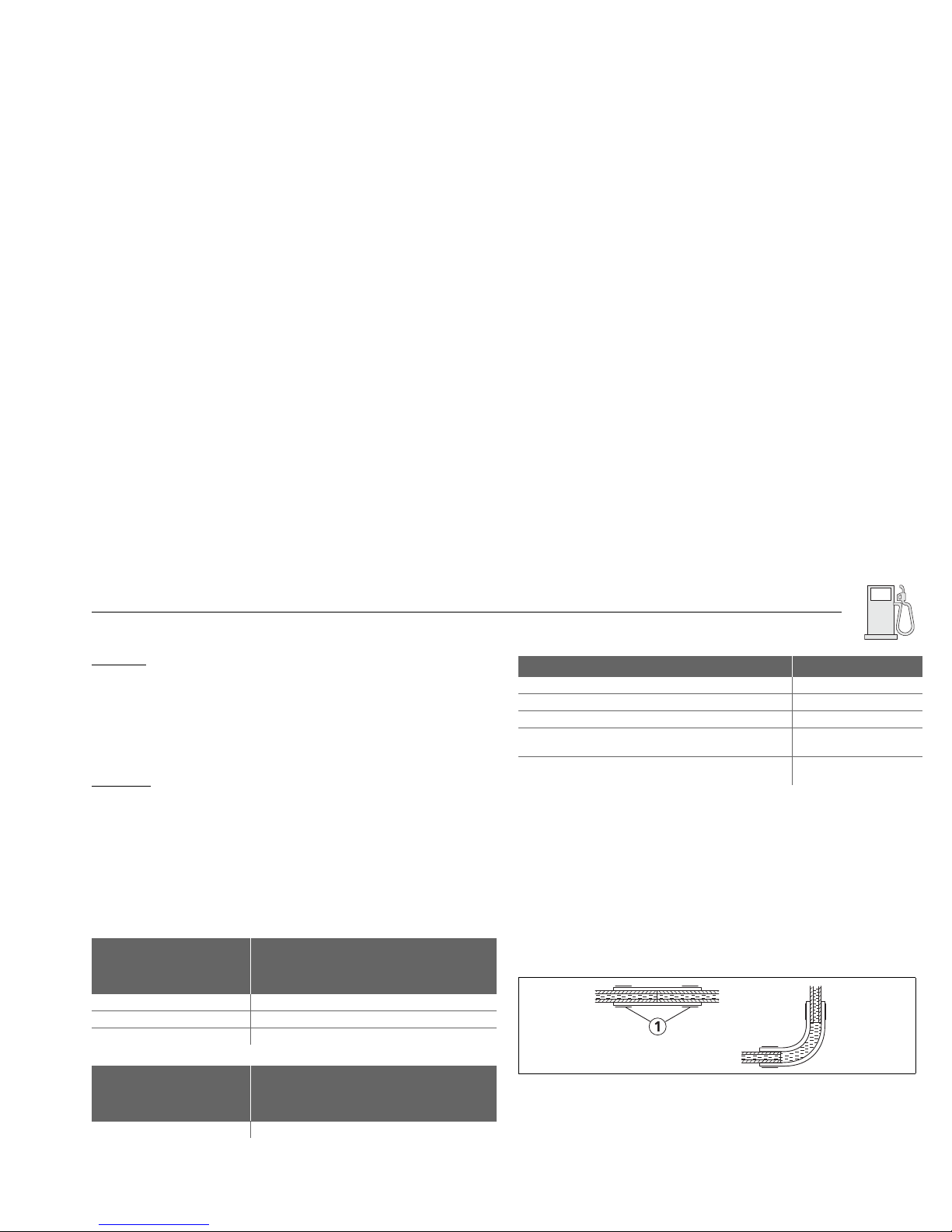
6.5.3. Verbindung von 2 Brennstoffleitungen mit Schlauch
Die richtige Verbindung von Brennstoffleitungen mit Schlauch ist in Abb. 12
dargestellt.
Auf Dichtigkeit achten!
Niveau Füllstand (Tank
oberhalb Brennstoffpumpe) H1 [m]
maximal zulässiger Brennstoffdruck an
der Entnahmestelle, p1 [bar]
H1 = 0 -0,1 < p1 <+0,5
0 < H
1
<1 -0,1 < p1 <+0,4
1 < H
1
<2 -0,1 < p1 <+0,3
Niveau Füllstand (Tank
unterhalb Brennstoffpumpe) H2 [m]
maximal zulässiger Brennstoffdruck an
der Entnahmestelle, p1 [bar]
0 <H2 <1,3 -0,1 < p1 <+0,5
Parameter Wert
Saugleitungslänge l1 [m] max. 5
Druckleitungslänge l
2
[m] max. 10
Saugleitungslänge l
1
+ Druckleitungslänge l2 [m] max. 12
Höhenunterschied Heizgerät - Brennstoffpumpe
(Heizgerät oberhalb Brennstoffpumpe) H
2
[m]
max. 3
Höhenunterschied Heizgerät - Brennstoffpumpe
(Heizgerät unterhalb Brennstoffpumpe) S
2
[m]
max. 1
Abb. 12 Rohr/Schlauchverbindung
1) Schlauchschelle
Page 25
Brennstoff Air Top Evo 40 / Air Top Evo 55
20
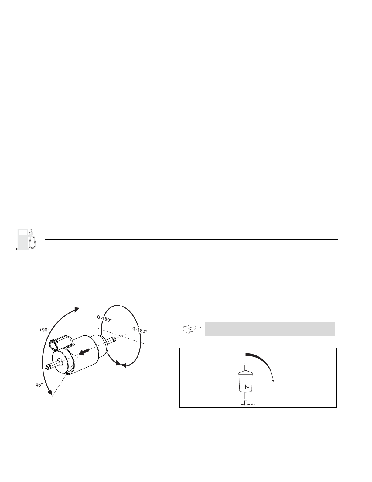
6.5.4. Brennstoffpumpe
Die Brennstoffpumpe ist ein kombiniertes Förder-, Dosier- und
Absperrsystem und unterliegt bestimmten Einbaukriterien (Einbaulagen
siehe Abb. 13).
Die Heizgeräte Air Top Evo 40 / Air Top Evo 55 dürfen ausschließlich mit der
Brennstoffpumpe DP 42 betrieben werden.
6.5.5. Einbauort
Die Brennstoffpumpe darf nicht im Strahlungsbereich heißer Fahrzeugteile
montiert werden. Ggf. ist ein Hitzeschild vorzusehen. Der bevorzugte
Einbauraum ist in Tanknähe.
Zulässige Umgebungstemperatur siehe Kapitel 13, "Technische Daten".
6.5.6. Einbau und Befestigung
Die Brennstoffpumpe ist mit einer schwingungsdämpfenden Aufhängung zu
befestigen. Die Einbaulage ist gemäß Abb. 13 (maximaler Neigungswinkel
Brennstoffpumpe, axiale Einbaulage Brennstoffpumpe) eingeschränkt.
Der Pfeil gibt die Brennstoffflussrichtung an.
6.5.7. Brennstofffilter
Muss mit verschmutztem Brennstoff gerechnet werden, ist ein geeigneter
Brennstofffilter (z. B. Webasto Brennstofffilter) einzubauen. Einbau nach
Möglichkeit senkrecht, max. jedoch waagerecht (siehe Abb. 14).
Abb. 13 Einbaulage Brennstoffpumpe DP 42
HINWEIS:
Einbaulage und Durchflussrichtung beachten.
Abb. 14 Brennstofffilter, Einbaulage und Durchflussrichtung
0° - 90°
Page 26
Air Top Evo 40 / Air Top Evo 55 Brennstoff
21
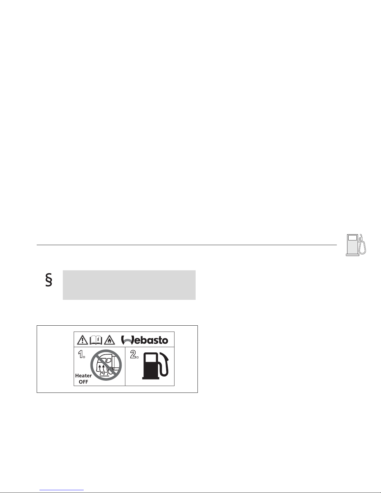
6.6. Aufkleber
Aufkleber „Bei Tankvorgang Heizgerät abschalten“ im Bereich des Einfüll-
stutzens anbringen (Beispiel siehe Abb. 15).
Am Einfüllstutzen muss ein Hinweis angebracht werden, dass
das Heizgerät vor dem Nachfüllen von Brennstoff abgeschaltet werden muss. [...]
(Forderung aus ECE-R 122, Punkt 5.3.3.3.).
Abb. 15 Aufkleber „Bei Tankvorgang Heizgerät abschalten“
Page 27
Brennluft Air Top Evo 40 / Air Top Evo 55
22
7Brennluftversorgung
7.1. Allgemein
Brennluftansaugleitung vom Heizgerät weg fallend verlegen.
Ist dies nicht möglich, an der tiefsten Stelle eine Wasserablaufbohrung
(ø 4 mm) anbringen.
Leitungsmündung so verlegen, dass sie nicht in Fahrtrichtung zeigt.
Leitungsmündung so verlegen, dass ein Zusetzen durch Verschmutzung
vermieden wird.
Die Luft für den Brennraum des Heizgeräts darf nicht aus dem
Fahrgastraum des Fahrzeugs angesaugt werden.
(Forderung aus ECE-R 122, Punkt 5.3.5.1.).
Der Lufteinlass muss so angeordnet oder geschützt sein, dass
er nicht durch Müll oder Gepäckstücke blockiert werden
kann.
(Forderung aus ECE-R 122, Punkt 5.3.5.2.).
Abb. 16 Vermeidung von Siphons
Abb. 17 Brennluftansaugleitung nicht in Fahrrichtung
Abb. 18 Vermeidung von Verschmutzung
Page 28
Air Top Evo 40 / Air Top Evo 55 Brennluft
23
7.2. Hinweise zur Brennluftansaugleitung
Eigenschaften Brennluftansaugleitung
Brennlufteintritt
Brennluft nur Räumen entnehmen, in denen sich keine Personen
aufhalten.
Brennluft nur aus einem kühlen, spritzwassergeschützten Bereich ent-
nehmen.
Leitungsmündung so positionieren, dass bei Wasserdurchfahrt kein Was-
ser eindringen kann.
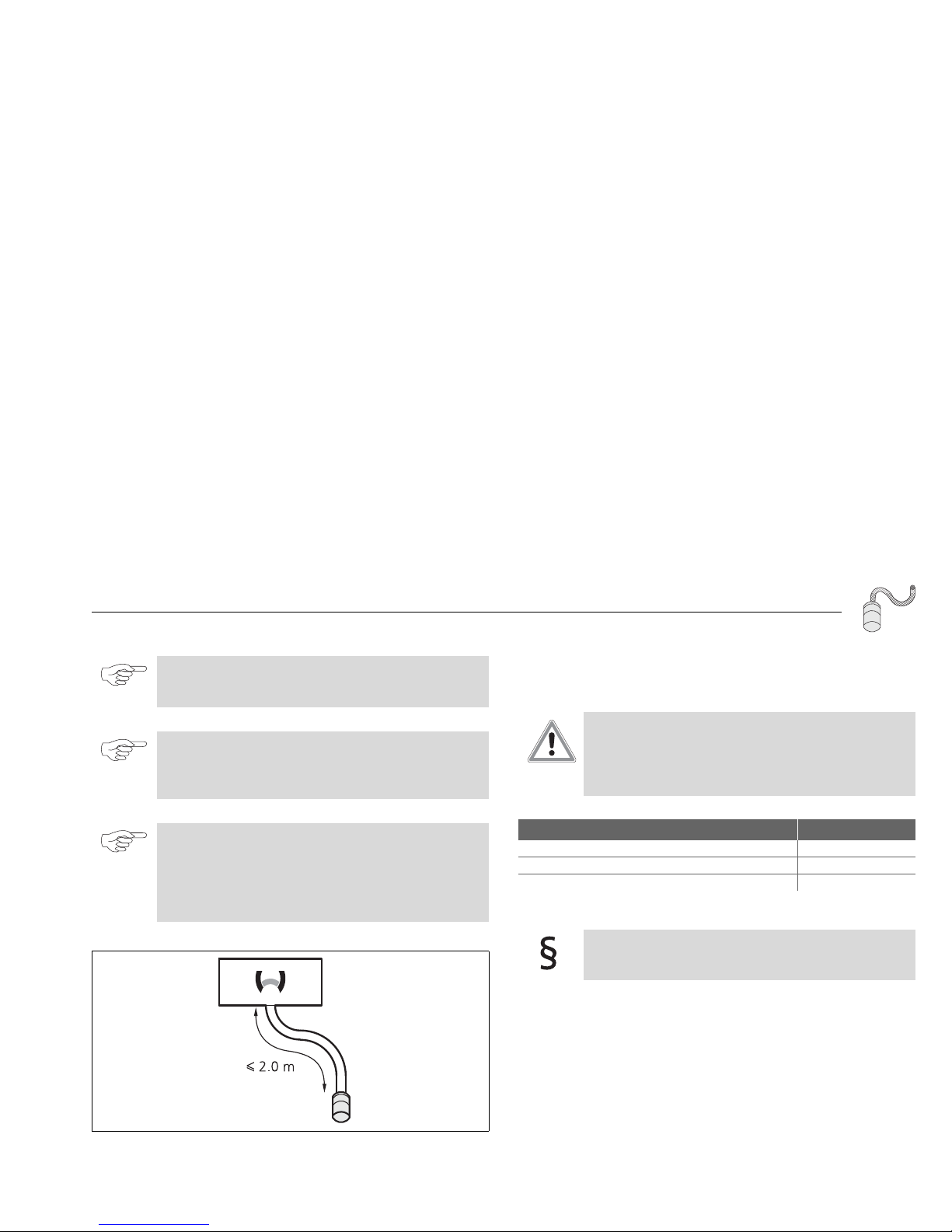
HINWEIS:
Eine Brennluftansaugleitung ist erforderlich.
Eine Minimallänge ist nicht vorgeschrieben.
HINWEIS:
Die Brennluftansaugleitung mit Brennluftansaugschalldämpfer darf eine max. Länge von 2,0 m nicht überschreiten.
HINWEIS:
Brennluftansaug- und Abgasleitung dürfen in Summe eine
max. Länge nicht überschreiten:
Mit Abgasschalldämpfer: 2,0 m
Ohne Abgasschalldämpfer: 5,0 m
Siehe auch Kapitel 8, "Abgasanlage".
Abb. 19 Länge Brennluftansaugleitung mit
Brennluftansaugschalldämpfer max. 2 m.
< 2.0 m
ACHTUNG:
Verwechslungsgefahr der Abgasleitung mit der
Brennluftansaugleitung!
Beschädigung des Brennstoffpumpenkabels
Die Abgasleitung nur am Abgasauslassstutzen anbauen
Brennluftansaugleitung Wert
Innendurchmesser 25 mm
Kleinster Biegeradius 50 mm
Max. Summe aller Biegungen 270°
Die Luft für den Brennraum des Heizgeräts darf nicht aus dem
Fahrgastraum des Fahrzeugs angesaugt werden.
(Forderung aus ECE-R 122, Punkt 5.3.5.1.).
Page 29

Brennluft Air Top Evo 40 / Air Top Evo 55
24
Brennluftansaugschalldämpfer
HINWEIS:
Bei einer Ansaugleitungslänge < 0,5 m muss ein
Brennluftansaugschalldämpfer eingebaut werden.
Page 30
Air Top Evo 40 / Air Top Evo 55 Abgas
25
8 Abgasanlage
8.1. Allgemein
Abgasleitung vom Heizgerät weg fallend verlegen.
Ist dies nicht möglich, an der tiefsten Stelle eine Wasserablaufbohrung
(ø 4 mm) anbringen.
Mündung der Abgasleitung so verlegen, dass sie nicht in Fahrtrichtung
zeigt.
Der Abgasauslass muss so angeordnet sein, dass keine Abgase über Belüftungseinrichtungen, Warmlufteinlässe oder geöffnete Fenster in das Fahrzeuginnere gelangen können.
(Forderung aus ECE-R 122, Punkt 5.3.4.1.).
HINWEIS:
Nur für ADR:
Fahrzeuge EX/II, EX/III, AT, FL und OX: siehe Kapitel 4.1,
"Anforderungen an Einbauort", Auszug aus der Richtlinie.
Die gesetzlichen Bestimmungen der ADR für die Verlegung
der Abgasleitung ECE-R 122, Anhang 9, Punkt 3 sind zu
beachten.
Abb. 20 Vermeidung von Kondensatbildung
Abb. 21 Mündung der Abgasleitung nicht in Fahrrichtung
Page 31

Abgas Air Top Evo 40 / Air Top Evo 55
26
Mündung der Abgasleitung so verlegen, dass ein Zusetzen durch Ver-
schmutzung vermieden wird.
8.2. Hinweise zur Abgasleitung
Die Abgasleitung ist am Heizgerät mit einer für die Abgasleitung geeigneten
Schelle zu sichern.
Zur Vermeidung der Taupunktunterschreitung kann eine geeignete
Isolierung verwendet werden.
Eigenschaften Abgasleitung
Abgasschalldämpfer
Der Betrieb des Heizgeräts ist auch ohne Abgasschalldämpfer zulässig.
Abgasschalldämpfer möglichst nahe am Heizgerät einbauen.
Dabei auf korrekte Einbaulage achten (siehe Abb. 23 und Abb. 24).
Die Durchflussrichtung ist beliebig.
Abb. 22 Vermeidung von Verschmutzung
HINWEIS:
Die Abgasleitung darf nicht durch den Innenraum geführt
werden.
HINWEIS:
Ein Ansaugen von Abgas in die Brennluft muss vermieden
werden.
HINWEIS:
Brennluftansaug- und Abgasleitung dürfen in Summe eine
max. Länge nicht überschreiten:
Mit Abgasschalldämpfer: 2,0 m
Ohne Abgasschalldämpfer: 5,0 m
Siehe auch Kapitel 7, "Brennluftversorgung".
ACHTUNG:
Verwechslungsgefahr der Abgasleitung mit der
Brennluftansaugleitung!
Beschädigung des Brennstoffpumpenkabels
Die Abgasleitung nur am Abgasauslassstutzen anbauen
Abgasleitung Wert
Innendurchmesser 24 mm
Kleinster Biegeradius 50 mm
Max. Summe aller Biegungen 270°
Minimallänge 0,5 m
Page 32

Air Top Evo 40 / Air Top Evo 55 Abgas
27
Mündung der Abgasleitung
Abgasleitung nicht weiter als 150 mm von der Mündung entfernt
befestigen, damit ein Winkel von 90° ± 10° sichergestellt ist (siehe Abb. 24).
Abb. 23 zulässige Einbaulage Abgasschalldämpfer
Durchflussrichtung beliebig
Abb. 24 Abgasschalldämpfer für Bootsapplikationen
Durchflussrichtung und Einbaulage beliebig
ACHTUNG:
Hitzeentwicklung durch falsch positionierte Mündung
der Abgasleitung!
Personen- oder Sachschaden durch Brand
Auf Einbaulage achten.
Abb. 25 zulässige Einbaulage der Mündung des Abgasleitung
Page 33

Elektrik Air Top Evo 40 / Air Top Evo 55
28
9 Elektrische Anschlüsse
Alle nicht benötigten Leitungen müssen am freien Ende isoliert werden!
Der elektrische Anschluss wird gemäß Schaltplan (Abb. 33 bis 38)
ausgeführt.
9.1. Anschluss bei Einbau in ein Fahrzeug zum Transport
gefährlicher Güter (ADR)
Für den Einbau von Heizgeräten Air Top Evo 40 D und Air Top Evo 55 D in
Fahrzeuge für den Transport gefährlicher Güter müssen zusätzlich die
Anforderungen der Richtlinie ECE-R 122, Anhang 9 - Verbrennungsheizung
erfüllt werden. Der elektrische Anschluss wird gemäß Schaltplan Abb. 34
ausgeführt.
9.2. Anschluss Heizgerät
Zum Anschluss des Kabelbaumes ist die Steuergerätabdeckung am Heizgerät
abzunehmen und der Kabelbaumstecker am Steuergerät anzustecken.
HINWEIS:
Bei Verwendung der Kombiuhr kann zur Komforterhöhung
ein Tastschalter als Fernbedienung im Bereich der Schlafstelle
angebracht werden. Der Anschluss erfolgt gemäß Schaltplan
Abb. 35.
Fahrzeuge EX/II, EX/III, AT, FL und OX:
Das Verbrennungsheizgerät darf nur von Hand eingeschaltet
werden können. Automatisches Einschalten über einen programmierbaren Schalter ist nicht zulässig.
(Forderung aus ECE-R 122, Anhang 9, Punkt 3.1.2.).
HINWEIS:
Der Schalter S5 muss so installiert werden, dass bei
Inbetriebnahme einer Fördereinrichtung Plus-Potenzial auf
den entsprechenden Eingang des Steuergerätes zugeschaltet
wird.
ACHTUNG:
Ist am Steuergeräteeingang X6/1 beim Einschalten kein
Massekontakt vorhanden, so sind alle ADR-Funktionen
wirkungslos.
Nach dem Zuschalten von Plus-Potenzial am
Steuergeräteeingang X6/1 (Nebenantrieb Ein) oder Motor
abstellen erfolgt ein Kurznachlauf von maximal 40 Sekunden.
Anschließend befindet sich das Steuergerät in der Betriebsart
„ADR-Verriegelung“.
ACHTUNG:
Um der gesetzlichen Forderung zu entsprechen, ist bei der
Ausrüstung mit Kombiuhr sicherzustellen, dass der Kontakt 4
an der Kombiuhr frei bleibt. Das Heizgerät kann somit nur mit
der Sofortheiztaste in Betrieb genommen werden.
Page 34

Air Top Evo 40 / Air Top Evo 55 Elektrik
29
Vor der Erstinbetriebnahme des Heizgeräts ist die Steuergerätabdeckung
aufzusetzen, um einen unzulässigen Austritt der Warmluft zu verhindern
(Heizgerätüberhitzung).
Der Kabeldurchgang kann wahlweise links oder rechts erfolgen.
Um sicherzustellen, dass die Kabeldurchführung in der
Steuergerätabdeckung dicht abschließt, ist die Kabeltülle auf dem
Kabelbaum entsprechend zu verschieben.
9.3. Anschluss Versorgungsspannung
Zur Absicherung des Heizgeräts muss eine Sicherung (nach
SAE J 1284, siehe auch Abb. 27) eingebaut werden. Der
Sicherungshalter, der im Lieferumfang enthalten ist, ist
vorzugsweise im Fahrzeuginnenraum einzubauen.
9.4. Einbau Bedienelemente
Abb. 26 Entfernen der Steuergerätabdeckung
HINWEIS:
Steuergerätabdeckung beidseitig mit stumpfer Klinge
abheben (Abb. 26 Pfeile).
ACHTUNG:
Um einen Nachlauf zu ermöglichen, darf das Heizgerät nicht
hart abgeschaltet (spannungslos) werden.
Eine Ansteuerung eines elektrischen Batterietrennschalters ist
möglich (siehe Schaltplan Abb. 35).
Abb. 27 Sicherungshalter, Einbaulage
F = 15 A (24 V)
F = 20 A (12 V)
Eine deutlich sichtbare Kontrollleuchte im Sichtfeld des
Bedieners muss anzeigen, ob das Heizgerät ein- oder ausgeschaltet ist.
(Forderung aus ECE-R 122, Anhang 7, Punkt 7.1.).
Page 35

Elektrik Air Top Evo 40 / Air Top Evo 55
30
9.4.1. Einbau Drehwähler
Der Kabelbaum ist zum Anschluss an den Drehwähler vorbereitet.
Zum Abziehen des Steckers nur am Steckerkorb ziehen.
Durch Ziehen am Kabelbaum wird der Steckerkorb verriegelt
(selbsthemmend).
ACHTUNG:
Das Air Top Evo 40 / Air Top Evo 55 ist ein eigenständiges,
motorunabhängiges System mit integrierter
Tem perat urreg elung.
Eine zusätzliche automatische Steuerung zum Zweck der
Temperaturregelung ist nicht erlaubt.
HINWEIS:
Das Bedienelement ist nur zum Einbau im
Fahrzeuginnenraum vorgesehen.
Der Lichtleiter muss am Drehknopf anliegen.
Abb. 28 Drehwähler
Abb. 29 Einbau des Drehwählers (richtig und falsch)
Page 36

Air Top Evo 40 / Air Top Evo 55 Elektrik
31
9.4.2. Anschluss Kombiuhr mit Adapterkabelbaum (optional)
1) Kombiuhr 1531
2) grau: Klemme 58
3) schwarz: Klemme 15
4) rot: Klemme 30
5) braun: Klemme 31
6) Adapterkabelbaum
Abb. 30 Anschluss Air Top Evo 40 und Air Top Evo 55 mit Kombiuhr 1531
Page 37

Elektrik Air Top Evo 40 / Air Top Evo 55
32
9.4.3. Einbau BedienelementAir Top Evo MultiControl MC04
(optional)
Für den Ausschnitt und die Bohrungen die Bohrschablone Bedienelement
Air Top Evo MultiControl (MC04) verwenden (siehe Kapitel 14, "Bohrschablonen").
Bedienelement mit den vorhandenen Steckern am Kabelbaum verbinden
(siehe Kapitel 10, "Schaltpläne", Abb. 36).
Bedienelement im Ausschnitt montieren.
Blendrahmen aufklipsen.
HINWEIS:
Das Bedienelement sollte an einer geeigneten Stelle (ebene
Fläche) im Sichtbereich eingebaut werden.
Das Bedienelement ist nur zum Einbau im
Fahrzeuginnenraum geeignet.
Beim Anschluss des Bedienelements an den Kabelbaum
sind die Hinweise auf den Aufklebern sowie die
Farbmarkierungen zu beachten.
Abb. 31 Einbau des Bedienelements Air Top Evo MultiControl (MC04)
Page 38

Air Top Evo 40 / Air Top Evo 55 Elektrik
33
Abb. 32 Anschluss Air Top Evo 40 und Air Top Evo 55 mit
Bedienelement Air Top Evo MultiControl (MC04)
1)
Bedienelement Air Top Evo MultiControl (MC04)
2) Farbmarkierungen beachten
3) optionaler Anschluss für:
Telestart / Thermo Call (nur 12 V)
Webasto Thermo Test PC-Diagnose
4) Kabelbaum (optional)
Page 39

Elektrik Air Top Evo 40 / Air Top Evo 55
34
10 Schaltpläne
Abb. 33 Schaltplan Air Top Evo 40 und Air Top Evo 55, 12V/24V mit Drehwähler und Fahrzeuggebläse,
Legende siehe Seite 40 und 41
Page 40

Air Top Evo 40 / Air Top Evo 55 Elektrik
35
Abb. 34 Schaltplan Air Top Evo 40 und Air Top Evo 55, 24V ADR-Betrieb mit Drehwähler,
Legende siehe Seite 40 und 41
Page 41

Elektrik Air Top Evo 40 / Air Top Evo 55
36
Abb. 35 Schaltplan Air Top Evo 40 und Air Top Evo 55, 12V/24V mit Kombiuhr 1531 und elektr. Batterietrennschalter,
Legende siehe Seite 40 und 41
Page 42

Air Top Evo 40 / Air Top Evo 55 Elektrik
37
Abb. 36 Schaltplan Air Top Evo 40 und Air Top Evo 55, 12V/24V mit Bedienelement Air Top Evo MultiControl (MC04) (Kabelbaum optional erhältlich),
Legende siehe Seite 40 und 41
Page 43

Elektrik Air Top Evo 40 / Air Top Evo 55
38
Abb. 37 Schaltplan Air Top Evo 40 und Air Top Evo 55 "Master Heizgerät", 12V/24V,
Legende siehe Seite 40 und 41
Page 44

Air Top Evo 40 / Air Top Evo 55 Elektrik
39
Abb. 38 Schaltplan Air Top Evo 40 und Air Top Evo 55 "Slave Heizgerät", 12V/24V ,
Legende siehe Seite 40 und 41
Page 45

Elektrik Air Top Evo 40 / Air Top Evo 55
40
10.1. Legende für Schaltpläne
Leitungsquerschnitte Leitungsfarben
< 7,5 m 7,5 - 15 m
0,75 mm2
1,0 mm
2
1,0 mm2
1,5 mm
2
1,5 mm2
2,5 mm
2
2,5 mm2
4,0 mm
2
4,0 mm
2
6,0 mm
2
HINWEIS:
Gestrichelt dargestellte Leitungen/Komponenten sind
optional und nicht im Lieferumfang / Kabelbaum
enthalten.
Abkürzung Farbe
bl
blau
br
braun
ge
gelb
gn
grün
gr
grau
or
orange
rt
rot
sw
schwarz
vi
violett
WS
weiß
Page 46

Air Top Evo 40 / Air Top Evo 55 Elektrik
41
Pos. Benennung Bemerkung
A1 Heizgerät Air Top Evo 40 / Air Top Evo 55
A2 Steuergerät Steuergerät 1580
B2 Raumtemperatursensor intern
B3 Ausblastemperatursensor Überhitzungsschutz
B4 Raumtemperatursensor extern
B5 Abgastemperatursensor Überhitzungsschutz / Flammwächter
EGlühstift
F1 Sicherung 15 A (24 V)
bzw. 20 A (12 V)
Flachsicherung SAE J 1284
F2 Sicherung 4 A Flachsicherung SAE J 1284,
nicht im Kabelbaum enthalten
F3 Sicherung 1 A Flachsicherung SAE J 1284
F4 Sicherung 4 A Flachsicherung SAE J 1284,
nicht im Kabelbaum enthalten
F5 Sicherung Wert in [A] zu wählen je nach Leitungsquer-
schnitt
H1 LED grün (in Pos. S1) Betriebsanzeige
H2 LED rot (in Pos. P) Beleuchtung Sofortheiztaste, Betriebsanzeige
H3 Anzeige (in Pos. P) Symbol Heizen, Betriebsanzeige
H4 Glühlampe / LED
(in Pos. P und S)
Anzeige- und Tastenbeleuchtung
H5 Glühlampe / LED Einschaltkontrolle Fördereinrichtung
max. 500 mA
K Relais mit Freilaufdiode für Fahrzeuggebläse
max. 500 mA
M1 Motor Brenn- und Heizluftläufer
M3 Motor Fahrzeuggebläse
P Kombiuhr 1531 Vorwahluhr und Temperaturwähler
Pos. Benennung Bemerkung
S Bedienelement Air Top Evo
MultiControl (MC04)
Einschalter, Wahlschalter für Zusatzfunk-
tionen und Temperaturwähler
S1 Bedienelement Drehwähler Einschalter und Temperaturwähler
S2 Schalter Lüften
S3 Schalter CO
2
-Einstellung
S4 Taster externe Sofortheiztaste
S5 Schalter Fördereinrichtungen / Nebenantrieb
S6 Schalter ein- oder zweipolig Trennschalter
S7 Batterietrennschalter elektronisch gesteuerter Trennschalter
max. 500 mA
V1/V2 Sperrdiode min. 500 mA
X1-X8 Steckverbindung an Pos. A2
X9 (a) Steckverbindung an Pos. S oder S1
X9 (b) Steckverbindung an Pos. S oder S2
X9 (c) Steckverbindung W-Bus, optional Anschluss Telestart (12 V)
oder Thermo Call
X1-X11 Steckverbindung Im Heizgerät am Steuergerät
X13 Steckverbindung an Pos. Y1
X14 Steckverbindung an Pos. P
X15 Steckverbindung zu Pos. S3
X16 Steckverbindung Anschluss Kabelbaum DP 42
X17 Steckverbindung Anschluss Kabelbaum DP 42
Y1 Brennstoffpumpe DP 42
Y2 Magnetventil/Pumpe Fördereinrichtungen / Nebenantrieb
max. 500 mA
Page 47

Elektrik Air Top Evo 40 / Air Top Evo 55
42
Hinweisnummern
(1) Mit Plus von Klemme 15/75 an Anschluss 10:
Dauerbetrieb bei Sofortheizen solange die Zündung eingeschaltet ist.
(2) Alle Heizgerätevarianten: Anschluss W-Bus Diagnose.
Heizgerätevarianten mit Bedienelement Air Top Evo MultiControl
(MC04) und Kombiuhr:
Anschluss Thermo Call
Anschluss Telestart (nur 12 V).
Heizgerätevariante Master: Anschluss Slave Heizgerät (Leitung ge/bl).
Vorkonfektionierte Leitung ist im Lieferumfang Slave enthalten.
(3) CO
2
-Einstellung (siehe Werkstatthandbuch).
(4) Erfolgt der Anschluss an Klemme 30, ist Dauerheizbetrieb bei
ausgeschalteter Zündung möglich!
In diesem Fall darf keine Verbindung zu Klemme 15/75 erfolgen!
(5) Leitungen grau und violett bei ADR-Funktion erforderlich.
Bei Nicht-ADR-Fahrzeugen sind die Leitungsenden zu isolieren und
zurückzubinden.
(6) Externer Raumtemperatursensor (optional).
Hinweis: Bei Heizgerätevariante Master ist der Sensor zwingend
erforderlich.
(7) Sicherung im Fahrzeug vorhanden.
(8) Pin 7 "Boost" nur bei Heizgerätevariante Ambulanz (Türkontakt an
Klemme 31).
(9) Anschluss notwendig bei Verwendung der Kombiuhr 1531 in ADR-
Fahrzeugen.
(10) Adapter Kabelbaum ist optional erhältlich.
Page 48

Air Top Evo 40 / Air Top Evo 55 Mechanik
43
11 Erstinbetriebnahme
Nach dem Einbau des Heizgeräts ist das Brennstoffversorgungssystem
sorgfältig zu entlüften.
11.1. Einbau / Erstinbetriebnahme Air Top Evo System
Installation
1. Einbau der Heizgeräte nach Einbauanweisung
2. Herstellung der elektrischen Anschlüsse nach Schaltplan (Abb. 37, Abb.
38)
3. Installation des Bedienelements und des externen Temperatursensors
12 Störungen
Tritt eine Störung ein, wird in der Betriebsanzeige ein Blinkcode, bzw. an der
Kombiuhr ein Fehlercode F .. ausgegeben.
Zur Behebung eines Fehlers ist nach Werkstatthandbuch vorzugehen.
HINWEIS:
Die Sicherheitshinweise in der Bedienungsanweisung sind zu
beachten!
Die Bedienungsanweisung vor Inbetriebnahme des Heizgeräts
unbedingt lesen.
HINWEIS:
Beim Einschalten der Heizgeräte konfiguriert sich das System
automatisch als Master und Slave.
Page 49

Technische Information Air Top Evo 40 / Air Top Evo 55
44
13 Technische Daten
Die technischen Daten verstehen sich, soweit keine Grenzwerte angegeben
sind, mit den bei Heizgeräten üblichen Toleranzen von 10 % bei einer
Umgebungstemperatur von +20 °C und bei Nennspannung.
13.1. Elektrische Bauteile
Steuergerät, Glühlampe in der Vorwahluhr und Glühstift sind entweder für
12 Volt oder 24 Volt ausgelegt.
Vorwahluhr (ohne Glühlampe), Ausblastemperatursensor, externer
Temperatursensor, Motor, Brennstoffpumpe, Abgastemperatursensor sind
für beide Betriebsspannungen ausgelegt..
13.2. Brennstoff für Air Top Evo 40 B (Benzin)
Brennstoff für Air Top Evo 55 B (Benzin)
Als Brennstoff eignet sich der vom Fahrzeughersteller vorgeschriebene
Brennstoff nach DIN EN 228.
13.3. Brennstoff für Air Top Evo 40 D (Diesel)
Brennstoff für Air Top Evo 55 D (Diesel)
Als Brennstoff eignet sich der vom Fahrzeughersteller vorgeschriebene
Dieselbrennstoff nach DIN EN 590.
Eine nachteilige Beeinflussung durch Additive ist nicht bekannt.
Bei einem Wechsel auf kältebeständige Brennstoffe muss das Heizgerät ca.
15 Minuten in Betrieb genommen werden, damit das Brennstoffsystem mit
neuem Brennstoff gefüllt wird.
Die Geräte Air Top Evo 40 D und Air Top Evo 55 D sind auch für den Betrieb
mit Biodiesel (FAME), der DIN EN 14214 entspricht, zugelassen.
Page 50

Air Top Evo 40 / Air Top Evo 55 Technische Information
45
* Werte in Klammern gelten für die erweiterte Heizleistung, welche bei jedem Start zeitbegrenzt aktiviert wird.
Heizgerät Betrieb Air Top Evo 40 B Air Top Evo 55 B Air Top Evo 40 D Air Top Evo 55 D
Typgenehmigung EMV: E1 03 5529 (Air Top Evo 40 / Air Top Evo 55)
Heizung: E1 00 0385 (Air Top Evo 40)
Heizung: E1 00 0386 (Air Top Evo 55)
Bauart Luftheizgerät mit Verdampfungsbrenner
Wärmestrom Regelbereich 1,7 bis 3,5 (4,0) kW 1,7 bis 5,0 (5,5) kW 1,5 bis 3,5 (4,0) kW 1,5 bis 5,0 (5,5) kW
Brennstoff Benzin
DIN EN 228
Diesel/Biodiesel
DIN EN 590
DIN EN 14214
Brennstoffverbrauch Regelbereich 0,18 bis 0,38 (0,43) kg/h
0,25 bis 0,51 (0,58) l/h
0,18 bis 0,54 (0,59) kg/h
0,25 bis 0,73 (0,80) l/h
0,15 bis 0,36 (0,41) kg/h
0,18 bis 0,43 (0,49) l/h
0,15 bis 0,51 (0,56) kg/h
0,18 bis 0,61 (0,67) l/h
Nennspannung 12 Volt 12 / 24 Volt
Betriebsspannungsbereich 10,5 bis 16 Volt 10,5 bis 16 Volt / 20,5 bis 31 Volt
Nennleistungsaufnahme Regelbereich 15 bis 40 (55) W 15 bis 95 (130) W 15 bis 40 (55) W 15 bis 95 (130) W
Zulässige Umgebungstemperaturen:
Heizgerät – Betrieb
– Lager
Brennstoffpumpe – Betrieb
– Lager
Drehwähler – Betrieb
– Lager
–40°C bis +40°C
–40°C bis +85°C
–40 °C bis +20 °C (Benzin), +30 °C (Diesel)
–40°C bis +85°C
–40°C bis +75°C
–40°C bis +85°C
Zulässige Brennluftansaugtemperatur –40°C bis +20°C
Einstellbereich für Innentemperatur Regelbereich +5 °C bis +35 °C
Volumenstrom der Warmluft gegen 0,5 mbar max. 132 (140) m
3
/h max. 200 (220) m3/h max. 132 (140) m3/h max. 200 (220) m3/h
Abmessungen Heizgerät Länge: 423 ± 2 mm
Breite: 148 ± 1 mm
Höhe: 162 ± 1 mm
Gewicht Heizgerät 5,9 kg
Page 51

Technische Information Air Top Evo 40 / Air Top Evo 55
46
14 Bohrschablonen
Abb. 39 Bohrschablone Heizgerät
Air Top Evo 40 / Air Top Evo 55
Page 52

Air Top Evo 40 / Air Top Evo 55 Technische Information
47
Abb. 40 Bohrschablone Bedienelement Air Top Evo MultiControl (MC04)
Page 53

Technische Information Air Top Evo 40 / Air Top Evo 55
48
Page 54

49
Air Top Evo 40 / Air Top Evo 55
Note
Mechanical system
Electrical system
Heated air
Fuel
Exhaust gas
Combustion air
Caution
Technical information
Extract from directive
1 Explanatory Notes on Document
To provide you with a quick overview of the individual working steps, you will find an identification mark on the outside top corner of the page in question.
Sections in italics contain an excerpt from the Directive ECE-R 122.
Page 55

Technical information Air Top Evo 40 / Air Top Evo 55
50
2 Regulations governing installation
2.1. Statutory regulations governing installation
Type approvals according to ECE-R 10 (EMC) and ECE-R 122 (heaters) exist
for heaters Air Top Evo 40 / Air Top Evo 55.
For approval numbers, see Chapter 13, "Technical Data".
For installation, see Part I and Annex 7 of directive ECE-R 122 first and
foremost.
2.2. Application of combustion heaters in vehicles for transporting
dangerous goods (ADR)
Vehicles intended for transporting dangerous goods are type-tested in
accordance with ECE-R105. The following measures have been derived for
our combustion heaters:
The electrical wiring harness must be sufficiently dimensioned to prevent
overheating. The electrical wiring harness must be sufficiently insulated.
All power circuits must be protected with fuses or automatic circuitbreakers.
The cables must be securely fastened and routed so that the lines are
sufficiently protected against mechanical and thermal loading.
The combustion heaters must be type-tested in accordance with ECER122 and must comply with Annex 9 – Additional regulations for vehicles
for transporting dangerous goods.
The combustion heaters and their exhaust gas routing shall be designed,
located, protected or covered so as to prevent any unacceptable risk of
heating or ignition of the load.
In the event of any leakage of the fuel line, the fuel shall drain to the
ground without coming into contact with hot parts of the vehicle or the
load.
The exhaust system as well as the exhaust pipes shall be so directed or
protected to avoid any danger to the load through heating or ignition.
Parts of the exhaust system situated directly below the fuel tank shall have
a clearance of at least 100 mm or be protected by a thermal shield.
The combustion heater shall be switched on manually. Programming
devices shall be prohibited. The combustion heater may be switched on
again manually after the vehicle engine has been switched off.
NOTE:
The provisions of these Directives are binding within the
territory governed by EU Directive 70/156/EEC and/or EC/
2007/46 (binding for new vehicle types as of 29/04/2009) and
should also be observed in countries in which there are no
special regulations!
NOTE:
Failure to follow the installation instructions will lead to the
invalidation of the type approval for the heater and
consequently the general operating permit for the vehicle.
NOTE:
Country-specific registration regulations must be complied
with.
Page 56

Air Top Evo 40 / Air Top Evo 55 Technical information
51
Requirement for the basic unit:
A maximum run-on period of 40 seconds is permitted when the combustion
he ater is s witched off. Onl y those co mbusti on hea ters ma y b e us ed with h eat
exchangers which are not demonstrably damaged by the reduced run-on
time of 40 seconds beyond their usual operating time.
2.3. Additional documentation to be used
These installation instructions contain all necessary
information and instructions with regard to the installation of
Air Top Evo 40 / Air Top Evo 55 heaters.
In addition, the operating instructions must also be observed.
Page 57

Technical information Air Top Evo 40 / Air Top Evo 55
52
3Use / version
3.1. Use
Webasto air heaters Air Top Evo 40 and Air Top Evo 55 are suitable for
heating of cabins, boats, trucks, minibuses, vans, ambulances and motor
homes
Defrosting the vehicle windows
Cargo heating
The heaters function independently of the vehicle engine. They are connect
to the fuel tank and to the vehicle's electrical system.
They may be used for vehicles with either water or air-cooled engines.
They are not approved for heating the space in which dangerous goods are
transported.
3.2. Version
Air Heater for "Petrol" Fuel (12 V)
Air Top Evo 40 B (petrol)
Air Top Evo 55 B (petrol)
Air Heater for "Diesel" Fuel (12 or 24 V)
Air Top Evo 40 D (Diesel)
Air Top Evo 55 D (Diesel)
Page 58

Air Top Evo 40 / Air Top Evo 55 Technical information
53
4Heater
The installation situation will depend on the vehicle type.
1)
Control element
2) Heater
3) Fuse
4) Tank extracting device
5) Fuel filter (optional)
6) Fuel pump
7) Exhaust silencer (optional)
8) Maximum permissible water passage height
Fig. 1 Installation example
1
78 6 5 4
2 3
Page 59

Technical information Air Top Evo 40 / Air Top Evo 55
54
4.1. Requirements for the installation location Only for ADR:
Body sections and any other components in the vicinity of the
heater must be protected from excessive heat and the possibility of fuel or oil contamination.
(Requirement from ECE-R 122, Point 5.3.2.1.).
The heater shall not constitute a risk of fire, even in the case
of overheating. This requirement shall be deemed to be met
if the installation ensures an adequate distance to all parts
and suitable ventilation, by the use of fire resistant materials
or by the use of heat shields.
(Requirement from ECE-R 122, Point 5.3.2.2.).
In the case of M2 and M3 vehicles, the heater must not be
positioned in the passenger compartment. However, an installation in an effectively sealed envelope which also complies with the conditions in paragraph 5.3.2.2. may be used.
(Requirement from ECE-R 122, Point 5.3.2.3.).
Every reasonable precaution should be taken in positioning
the heater to minimize the risk of injury and damage to personal property.
(Requirement from ECE-R 122, Point 5.3.2.5.).
EX/II, EX/III, AT, FL, and OX vehicles:
The combustion heaters and their exhaust gas routing shall
be designed, located, protected or covered so as to prevent
any unacceptable risk of heating or ignition of the load. This
requirement shall be considered as fulfilled if the fuel tank
and the exhaust system of the appliance conform to the following provisions:
- Any fuel tanks for supplying the appliance shall meet
the following requirements:
a) In the event of any leakage, the fuel shall drain
to the ground without coming into contact with
hot parts of the vehicle or the load;
[...]
- The exhaust system as well as the exhaust pipes shall
be so directed or protected to avoid any danger to the
load through heating or ignition. Parts of the exhaust
system situated directly below the fuel tank (diesel)
shall have a clearance of at least 100 mm or be protected by a thermal shield.
Compliance with this paragraph shall be verified on the completed vehicle.
(Requirement from ECE-R 122, Annex 9, Point 3.1.1).
Page 60

Air Top Evo 40 / Air Top Evo 55 Technical information
55
The heater may be fitted both in the interior or on the exterior of the vehicle.
Exterior
Ensure that the heater is fitted in an area which is protected from splash-
ing water and spray.
The heater should be installed so as to prevent the penetration of water if
the vehicle is driven through water.
Insert a base seal between the heater and the support area.
The maximum permissible water passage height (fording depth) is
dependent on the vehicle (see Fig. 1).
Passenger compartment
Insert a base seal between the heater and the support area.
FL vehicles:
The combustion heaters shall be put out of operation by at
least the following methods:
a) intentional manual switching off from the driver’s
cab;
b) stopping of the vehicle engine; in this case the heat-
ing device may be restarted manually by the driver;
c) start-up of a feed pump on the motor vehicle for the
dangerous goods carried.
[...]
(Requirement from ECE-R 122, Annex 9, Point 3.3.1).
NOTE:
If the heater is located within reach of the driver, it must
always be installed with contact protection.
Page 61

Technical information Air Top Evo 40 / Air Top Evo 55
56
4.2. Installation of the heater
1)
Cold air inlet
2) Cable outlet (either right or left)
3) Hot air outlet
4) Exhaust gas outlet
5) Fuel inlet
6) Combustion air inlet
A) Space requirement for hot air outlet
B) Space requirement for cold air inlet
C) Space requirement for removal of the
heater
Fig. 2 Dimensions and space requirement [mm]
1
6 5 4
2 3
B AC
2
Page 62

Air Top Evo 40 / Air Top Evo 55 Technical information
57
Determine the space requirement and the installation position (see Fig. 2,
Fig. 4 and Fig. 5).
Observe the inclination angle (see Fig. 4 and Fig. 5).
For unevenness on a larger scale, smooth out the mounting surface.
Drill the fastening holes and openings (see Fig. 39) using the drilling tem-
plate.
IMPORTANT
Overheating of the heater due to blockage of the
heating air rotor!
Damage to the heater
Ensure that the heater enclosure is not in contact with any
part of the heater in the installation position (see Fig. 3).
Fig. 3 After installation, the casing must not be in contact with
any parts of the vehicle body.
Fig. 4 Permissible installation positions for the diesel heater
Fig. 5 Permissible installation positions for the petrol heater
NOTE:
The support area for the heater foot must be flat. The base
seal can compensate for unevenness of max. 1 mm.
NOTE:
A special tool is available to drill the openings and to draw the
mounting surface flat (available from Webasto).
Page 63

Technical information Air Top Evo 40 / Air Top Evo 55
58
Insert the base seal.
Remove all year data from the type label except for the installation year.
Fasten the heater. In doing so, tighten nuts M6 to 6 Nm (–0 Nm, +1 Nm).
If the type label is not clearly legible following heater installation, a dupli-
cate model plate must be used.
4.3. Construction as Air Top Evo system
Heaters Air Top Evo 40 and Air Top Evo 55 (diesel) can be fitted as a system
using 2 heater units.
Here Unit 1 is defined as the master heater and Unit 2 as the slave heater.
The control element and an external temperature sensor (T) are connected
to the master heater (see wiring diagram Fig. 37). The slave heater is
connected in accordance with the wiring diagram (see Fig. 38). The heaters
communicate via a serial bus system.
IMPORTANT
When the heater is dismantled and then reinstalled, the base
seal must be replaced.
The label referred to in Annex 7, paragraph 4, or a duplicate,
must be positioned so that it can be easily read when the
heater is installed in the vehicle.
(Requirement from ECE-R 122, Point 5.3.2.4.).
NOTE:
The type label must be affixed in a secure position where it
cannot be damaged and must be clearly legible following
installation of the heater.
IMPORTANT
The use of an Air Top Evo systems is not authorised for the
transportation of hazardous goods (ADR)!
Page 64

Air Top Evo 40 / Air Top Evo 55 Technical information
59
Fig. 6 Installation of Air Top System
1) Unit 1
2) Unit 2
3) Control element
4) Temperature sen s or
5) Bus System
Page 65

Cold air and hot air Air Top Evo 40 / Air Top Evo 55
60
5 Cold air and hot air
5.1. General Information
Both recirculation and fresh air modes are possible.
Temperature c on trol
The control unit is fitted with an internal room temperature sensor.
Optionally an external temperature sensor can also be used. Depending on
the intake temperature and the nominal temperature which has been set,
the controller regulates the heater within the corresponding heating capacity
range. The heating output is regulated so that after the preselected cabin
temperature (nominal temperature) has been quickly obtained, it is also
maintained at the preselected value.
Fresh air mode
During fresh air mode, ensure that the cold air is drawn from an area which
is protected from splashing water and spray. The fresh air inlet must be
installed above the permissible water passage height for the respective
vehicle.
Assembly in enclosed boxes
To prevent heat accumulation and subsequent overheating, ensure that hot
air cannot directly enter the enclosed boxes.
The heating air supply may be fresh or recirculated air and
must be drawn from a clean area not likely to be contaminated by exhaust fumes emitted either by the propulsion engine,
the combustion heater or any other vehicle source.
(Requirement from ECE-R 122, Point 5.3.6.1.)
NOTE:
The heater must not be integrated into the vehicle’s air
system.
NOTE:
The direct intake of hot air must be avoided (see Fig. 7).
A short-circuit in the air flow is not permitted.
Fig. 7 Cold air inlet and hot air outlet
NOTE:
During fresh air mode, an external temperature sensor must
be installed in the cabin to be heated.
Page 66

Air Top Evo 40 / Air Top Evo 55 Cold air and hot air
61
Position of the hot air openings Characteristics of the cold and hot air lines
Recommended inside diameter of the hot air line:
90 mm at Air Top Evo 55
80 mm at Air Top Evo 40
Location of cold air and warm air ducting
Maximum pressure difference between the inlet and outlet side of the
heater:
Air Top Evo 40: 2.0 hPa
Air Top Evo 55: 3.0 hPa
The hot air ducting must be installed or protected in the vehicle in such a way that prevents any risk of injury or damage
in the event of contact.
(Requirement from ECE-R 122, Point 5.3.7.1.)
The air outlet must be so positioned or guarded that blocking
by rubbish or luggage is unlikely.
(Requirement from ECE-R 122, Point 5.3.7.2.)
IMPORTANT
In vehicles used to transport people, the warm air outlet
opening is to be directed in such a way that it is at least 20 cm
away from all body parts.
NOTE:
The hot air outlet opening must not blow directly onto
temperature-sensitive parts.
NOTE:
When selecting the position of the hot air outlet openings,
pay attention to the following:
No airborne short-circuit between the vehicle heater and
the cold air inlet of the Air Top Evo
No airborne short-circuit between the cold inlet and the
hot air outlet of the Air Top Evo (Fig. 7)
NOTE:
For the warm air ducting, use only materials with a continuous temperature resistance of 130 °C (temporary 150 °C).
The inlet duct must be protected by mesh or other suitable
means.
(Requirement from ECE-R 122, Point 5.3.6.2.)
IMPORTANT
Use without a cold air inlet hose!
Risk of injury from the rotating hot air fan!
If you operate the heater without a cold air inlet hose, you
must install the inlet grille supplied with the heater
IMPORTANT
If this pressure difference is exceeded, the heating capacity
will be reduced.
Page 67

Cold air and hot air Air Top Evo 40 / Air Top Evo 55
62
Installation of the cold air and warm air ducting
Secure the cold and hot air lines at all connection points.
5.2. External temperature sensor (optional)
Install the external temperature sensor in the cabin to be heated:
at medium height;
on surfaces which are as vertical as possible.
NOTE:
The temperature sensor must not
be exposed directly to hot air (from the vehicle's heating
system or from the Air Top Evo 40 / Air Top Evo 55).
be installed close to heat sources (for example the vehicle’s
own heating system).
be placed in direct sunlight (for example on the dashboard).
be installed behind curtains or the like.
Page 68

Air Top Evo 40 / Air Top Evo 55 Fuel
63
6Fuel supply
6.1. General Information
The fuel is drawn from the vehicle fuel tank, the vehicle fuel line or from a
separate fuel tank.
6.2. Integration in the vehicle's supply line or return line
The fuel filler must not be situated in the passenger compartment and must be provided with an effective cap to prevent
fuel spillage.
(Requirement from ECE-R 122, Point 5.3.3.1.).
In the case of liquid fuel heaters, where a supply separate
from that of the vehicle is provided, the type of fuel and its
filler point must be clearly labelled.
(Requirement from ECE-R 122, Point 5.3.3.2.).
NOTE:
Only for ADR:
EX/II, EX/III, AT, FL and OX vehicles: see Chapter 4.1,
"Requirements for the installation location", excerpt from
directive.
The statutory regulation of ADR governing fuel tanks, ECER 122, Annex 9, Point 3, must be adhered to.
NOTE:
–Fuel extraction must be almost pressureless.
– Where fuel is drawn from the return line, you must ensure
that this line is not blocked by check valves. Also make
sure that the return line reaches to the bottom of the fuel
tank.
– A zero flow must never occur in the vehicle system as a
result of fuel extraction.
– For extraction from the swirl pot, ensure that the swirl pot
is not completely empty.
Page 69

Fuel Air Top Evo 40 / Air Top Evo 55
64
6.3. Integration via the vehicle's fuel delivery unit
See also Chapter 4, "Heater" (Fig. 1, "Installation example").
Retrofitting of the fuel extractor for a plastic fuel tank is performed only via
the fuel delivery unit.
The tank extracting device should be installed as shown in Fig. 9.
Fig. 8 Webasto fuel extractor
1) from tank
2) to fuel pump
3) to engine
Fig. 9 Webasto tank extracting device
1) Webasto tank extracting device
2) Original vehicle fuel delivery unit with hole
Page 70

Air Top Evo 40 / Air Top Evo 55 Fuel
65
The mating surface of the tank extracting device must he clean, even and
burr-free.
When fitting the tank extracting device in the fuel delivery unit, make sure
the standpipe is correctly installed. The standpipe must not affect the
function of the fuel delivery unit, including the fuel gauge, in any operating
state.
The length of the standpipe must be selected so that when installed, a
minimum distance of 10 mm above the tank bottom or 20 above the bottom
of the fuel delivery unit is guaranteed.
The safety measures specified by the vehicle manufacturer and the
corresponding torques must be observed.
6.4. Integration via the fuel tank drain screw
The fuel can also be extracted via the fuel tank drain screw (see Fig. 10).
This separate fuel extraction precludes any effect of pressure.
Fig. 10 Fuel extraction from the plastic tank
(Extraction via tank drain screw)
1) Plastic tank
2) Sealing ring
Page 71

Fuel Air Top Evo 40 / Air Top Evo 55
66
6.5. Fuel lines
Only use fuel lines with 2 mm inner diameter.
The fuel line is divided into the intake line and the delivery line. As a result,
the intake line is a connection between the fuel tank and the fuel pump,
while the delivery line produces the connection between the fuel pump and
the heater.
6.5.1. Line installation
When installing the fuel line, it must be kept as short as possible.
See Fig. 11.
The line must be installed protected against damage (e.g. stone impact).
The fuel line must be routed in cool areas to prevent the formation of
bubbles due to warming. High fuel temperatures can cause heater
malfunctions.
Fuel lines must be fastened in accordance with the latest technology.
Damage of the fuel line must be avoided.
Fig. 11 Fuel supply
H
1
D
1
l
1
l
2
l
2
H
2
l
1
D
2
S
2
D
2
D
1
S
1
Page 72

Air Top Evo 40 / Air Top Evo 55 Fuel
67
Intake side:
D1: Inner diameter of the fuel line = 2 mm.
H
1
: Fill level (tank above fuel pump) [m]
S1: Fill level (tank under fuel pump) [m]
l
1
: Length of fuel line [m]
Pressure side:
D2: Inner diameter of the fuel line = 2 mm.
H
2
: Height difference heater - fuel pump
(Heater above fuel pump) [m]
S
2
: Height difference heater - fuel pump
(Heater below fuel pump) [m]
l
2
: Length of fuel line [m]
6.5.2. Line design
Only steel and plastic lines made of light and temperature-resistant PA11 or
PA12 (e.g. Mecanyl RWTL) and in accordance with EN 73378 may be used
as fuel lines.
6.5.3. Connecting 2 fuel lines with a hose
The correct connection of fuel lines with a hose is shown in Fig. 12.
Ensure there are no leaks!
Fill level (tank above fuel
pump) H1 [m]
maximum permissible fuel pressure at
extraction point , p1 [bar]
H1 = 0 -0,1 < p1 <+0,5
0 < H
1
<1 -0,1 < p1 <+0,4
1 < H
1
<2 -0,1 < p1 <+0,3
Fill level (tank below fuel
pump) H
2
[m]
maximum permissible fuel pressure at
extraction point , p
1
[bar]
0 <H2 <1,3 -0,1 < p1 <+0,5
Parameter Value
Length of intake line l1 [m] max. 5
Length of delivery line l
2
[m] max. 10
Length of intake line l
1
+ Length of delivery line l2 [m] max. 12
Height difference heater - fuel pump
(Heater above fuel pump) H
2
[m]
max. 3
Height difference heater - fuel pump
(Heater below fuel pump) S
2
[m]
max. 1
Fig. 12 Pipe / hose connection
1) Hose clamp
Page 73

Fuel Air Top Evo 40 / Air Top Evo 55
68
6.5.4. Fuel pump
The fuel pump is a combined delivery, dosing and shut-off system and is
subject to specific installation criteria (see Fig. 13).
The Air Top Evo 40 / Air Top Evo 55 heater may only be operated with the
DP 42 fuel pump.
6.5.5. Installation location
The fuel pump must not be installed within range of the radiated heat from
hot vehicle parts. A heat shield must be used if necessary. The pump should
preferably be installed near the tank.
See for the permissible ambient temperature Chapter 13, "Technical Data".
6.5.6. Installation and attachment
The fuel pump must be secured with a vibration-damping mounting. The
installation position is restricted as shown in Fig. 13 (maximum inclination of
fuel pump, axial installation position of fuel pump).
The arrow indicates the direction of flow of the fuel.
6.5.7. Fuel filter
If the fuel is contaminated, a suitable fuel filter (e.g. Webasto fuel filter) must
be installed. Install vertically if possible, however at least horizontally (see Fig.
14).
Fig. 13 Installation position of DP 42 fuel pump
NOTE:
Note the installation position and direction of flow.
Fig. 14 Fuel filter, installation position and direction of flow
0° - 90°
Page 74

Air Top Evo 40 / Air Top Evo 55 Fuel
69
6.6. Label
Apply the sticker "Switch off heater when refuelling" near the filler neck
(see Fig. 15 for an example).
A notice, indicating that the heater must be shut down before
refuelling, must be affixed to the fuelling point. [...]
(Requirement from ECE-R 122, Point 5.3.3.3.).
Fig. 15 Sticker "Switch off heater when refuelling"
Page 75

Combustion air Air Top Evo 40 / Air Top Evo 55
70
7 Combustion air supply
7.1. General Information
Install the combustion air intake pipe falling away from the heater.
If this is not possible, a water drain hole with a diameter of 4 mm must be
made at its lowest point.
Lay the opening of the pipe in such a way that it does not point in the di-
rection of travel.
Install the pipe opening so that clogging due to dirt is avoided.
The air for the combustion chamber of the heater must not
be drawn from the passenger compartment of the vehicle.
(Requirement from ECE-R 122, Point 5.3.5.1.).
The air inlet must be so positioned or guarded that blocking
by rubbish or luggage is unlikely.
(Requirement from ECE-R 122, Point 5.3.5.2.).
Fig. 16 Preventing siphons
Fig. 17 Combustion air intake pipe not pointing in the direction of
travel
Fig. 18 Preventing contamination
Page 76

Air Top Evo 40 / Air Top Evo 55 Combustion air
71
7.2. Notes on the combustion air intake pipe
Characteristics of the combustion air intake pipe
Combustion air inlet
The combustion air should only be drawn from areas in which no persons
are present.
The combustion air should only be extracted from a cool area which is
protected from splashing water.
The pipe opening should be positioned so as to prevent the penetration
of water if the vehicle is driven through water.
NOTE:
A combustion air intake pipe is required.
A minimum length is not required.
NOTE:
The combustion air intake pipe with combustion air intake silencer must not exceed a max. length of 2.0 m.
NOTE:
The maximum total combined length of the combustion air
intake pipe and the exhaust pipe must not exceed:
With exhaust silencer: 2.0 m
Without exhaust silencer: 5.0 m
See also Chapter 8, "Exhaust system".
Fig. 19 Max. 2 m length of combustion air intake pipe with
combustion air intake silencer
< 2.0 m
IMPORTANT
Risk of confusing the exhaust pipe with the combustion
air pipe!
Damage to the combustion air pump cable
Attach the exhaust pipe only to the exhaust connection
piece
Combustion air intake pipe Value
Inner diameter 25 mm
Minimum bending radius 50 mm
Max. sum of all bends 270°
The air for the combustion chamber of the heater must not
be drawn from the passenger compartment of the vehicle.
(Requirement from ECE-R 122, Point 5.3.5.1.).
Page 77

Combustion air Air Top Evo 40 / Air Top Evo 55
72
Combustion air intake silencer
NOTE:
A combustion air intake silencer must be installed for intake
pipe lengths < 0.5 m.
Page 78

Air Top Evo 40 / Air Top Evo 55 Exhaust gas
73
8 Exhaust system
8.1. General Information
The exhaust line must be installed falling away from the heater.
If this is not possible, a water drain hole with a diameter of 4 mm must be
made at its lowest point.
Lay the opening of the exhaust pipe in such a way that it does not point
in the direction of travel.
The exhaust outlet must be located so as to prevent emissions
from entering the vehicle through ventilators, heated air inlets or opening windows.
(Requirement from ECE-R 122, Point 5.3.4.1.).
NOTE:
Only for ADR:
EX/II, EX/III, AT, FL and OX vehicles: see Chapter 4.1,
"Requirements for the installation location", excerpt from
directive.
The statutory regulation of ADR governing the routing of the
exhaust line, ECE-R 122, Annex 9, Point 3, must be adhered
to.
Fig. 20 Preventing the formation of condensate
Fig. 21 Opening of exhaust pipe not pointing in the direction of
travel
Page 79

Exhaust gas Air Top Evo 40 / Air Top Evo 55
74
The opening of the exhaust line must be installed so as to prevent clog-
ging due to dirt.
8.2. Notes on the exhaust pipe
The exhaust pipe must be secured to the heater with an appropriate clamp
for this pipe.
To prevent falling below the dew point, suitable insulation can be fitted.
Characteristics of the exhaust pipe
Exhaust silencer
The heater may also be operated without an exhaust silencer.
Install the exhaust silencer as close as possible to the heater.
During installation, pay attention to the correct installation position (see
Fig. 23 and Fig. 24).
The flow direction is arbitrary.
Fig. 22 Preventing contamination
NOTE:
The exhaust pipe must not be routed through the passenger
compartment.
NOTE:
Exhaust gas must be prevented from entering the combustion
air.
NOTE:
The maximum total combined length of the combustion air
intake pipe and the exhaust pipe must not exceed:
With exhaust silencer: 2.0 m
Without exhaust silencer: 5.0 m
See also Chapter 7, "Combustion air supply".
IMPORTANT
Risk of confusing the exhaust pipe with the combustion
air pipe!
Damage to the combustion air pump cable
Attach the exhaust pipe only to the exhaust connection
piece
Exhaust pipe Value
Inner diameter 24 mm
Minimum bending radius 50 mm
Max. sum of all bends 270°
Minimum length 0.5 m
Page 80

Air Top Evo 40 / Air Top Evo 55 Exhaust gas
75
Opening of the exhaust pipe
Do not secure the exhaust pipe more than 150 mm away from the opening
to ensure an angle of 90° ± 10° (see Fig. 24).
Fig. 23 Permissible installation location for the exhaust silencer
Arbitrary flow direction
Fig. 24 Exhaust silencer for boat applications
Flow direction and installation position arbitrary
IMPORTANT
Parts can become hot due to the incorrect position of
the exhaust pipe opening!
Risk of injury to persons or damage to property due to fire
Pay attention to the installation position.
Fig. 25 Permissible installation position for the exhaust pipe opening
Page 81

Electrical system Air Top Evo 40 / Air Top Evo 55
76
9 Electrical connections
All lines that are not required must be insulated at their free end!
The electrical connection of the heater is designed as shown in the wiring
diagrams (Fig. 33 to 38).
9.1. Connection for installation in a vehicle for the transportation of
hazardous goods (ADR)
When installing heaters Air Top Evo 40 D and Air Top Evo 55 D in vehicles
for the transportation of dangerous goods, the requirements of Directive
ECE-R 122, Annex 9 - Combustion Heater must also be met. The electrical
connection of the heater is designed as shown in the wiring diagram in Fig.
34.
9.2. Heater connection
To connect the wiring harness, remove the control unit cover on the heater
and connect the wiring harness plug to the control unit.
NOTE:
If the combination timer is used, a push button may be
installed in the sleeping section to act as a remote control and
improved comfort. The connections must be made as shown
in the wiring diagram in Fig. 35.
EX/II, EX/III, AT, FL and OX vehicles:
The combustion heater shall be switched on manually. Programming devices shall be prohibited.
(Requirement from ECE-R 122, Annex 9, Point 3.1.2.).
NOTE:
Switch S5 must be installed in such a way that a positive
potential is connected to the appropriate input of the control
unit when a pumping device is switched on.
IMPORTANT
All ADR functions are ineffective if there is no earth at control
unit input X6/1 when the system is switched on.
The control unit continues to run briefly for a maximum of 40
seconds when a positive voltage is connected to control unit
input X6/1 (auxiliary device on) or the engine is switched off.
The control unit then switches to the "ADR Lock-Out"
operating mode.
IMPORTANT
In order to comply with legal requirements, when fitting the
combination timer it must be ensured that contact 4 on the
combination timer remains free. The heater can then only be
taken into operation using the immediate heat button.
Page 82

Air Top Evo 40 / Air Top Evo 55 Electrical system
77
Before using the heater for the first time fit the control unit cover to prevent
the non-permitted escape of hot air (heater overheating).
The cable passage can be placed at either the left or right side.
To ensure that the cable passage in the control unit cover seals correctly,the
cable grommet is to be adjusted appropriately on the wiring harness.
9.3. Supply voltage connection
To protect the heater, a fuse (to SAE J 1284, also see Fig. 27)
must be fitted. It is preferable that the fuse holder supplied
with the heater is installed in the vehicle interior.
9.4. Installation of control element
Fig. 26 Removing the control unit cover
NOTE:
Raise the control unit cover on both sides using a blunt blade
(Figure 26 arrows).
IMPORTANT
To enable a run-on period, never perform a hard shut-down
of the heater (de-energised).
It is possible to actuate an electrical battery isolator (see
wiring diagram Fig. 35).
Fig. 27 Fuse holder, installation position
F = 15 A (24 V)
F = 20 A (12 V)
A clearly visible tell-tale in the operator’s field of view shall inform when the combustion heater is switched on or off.
(Requirement from ECE-R 122, Annex 7, Point 7.1.).
IMPORTANT
The Air Top Evo 40 / Air Top Evo 55 is a standalone system
which is independent of the motor with integrated
temperature control.
Additional automatic control for the purpose of temperature
regulation is not permitted.
Page 83

Electrical system Air Top Evo 40 / Air Top Evo 55
78
9.4.1. Installation of rotary selector
The wiring harness is prepared for connection to the rotary selector.
Simply pull on connector housing to unplug the connector.
The connector housing can be locked (self-locking action) by simply pulling
on the wiring harness.
NOTE:
The control element is only intended for installation in the
passenger compartment.
The fibre optic cable must be in contact with the rotary
knob.
Fig. 28 Rotary selector
Fig. 29 Installation of the rotary selector (correct and incorrect)
Page 84

Air Top Evo 40 / Air Top Evo 55 Electrical system
79
9.4.2. Connection of combination timer with adapter wiring harness (optional)
1) Combination timer 1531
2) grey: Terminal 58
3) black: Terminal 15
4) red: Terminal 30
5) brown: Terminal 31
6) Adapter wiring harness
Fig. 30 Connection of Air Top Evo 40 and Air Top Evo 55 to combination timer 1531
Page 85

Electrical system Air Top Evo 40 / Air Top Evo 55
80
9.4.3. Installation of the Air Top Evo MultiControl control element
(MC04)
Use the Air Top Evo MultiControl (MC04) control element drilling template
for the cut-out and the drill holes (see Chapter 14, "Drilling templates").
Connect the control element to the wiring harness using the existing con-
nectors (see Chapter 10, "Wiring diagrams", Fig. 36).
Install the control element in the cut-out.
Clip on the trim frame.
NOTE:
The control element should be installed in a suitable
location (on a flat surface) in the area visible to the driver.
The control element is only intended for installation in the
passenger compartment.
When connecting the control element to the wiring
harness, the instructions on the stickers and the colour
coding must be observed.
Fig. 31 Installation of the Air Top Evo MultiControl (MC04) control
element
Page 86

Air Top Evo 40 / Air Top Evo 55 Electrical system
81
Fig. 32 Connection of Air Top Evo 40 and Air Top Evo 55 to the Air
Top Evo MultiControl (MC04) control element
1)
Control element for Air Top Evo MultiControl (MC04)
2) Observe coloured markings
3) Optional connection for:
Telestart / Thermo Call (12 V only)
Webasto Thermo Test PC Diagnosis
4) Wiring harness (optional)
Page 87

Electrical system Air Top Evo 40 / Air Top Evo 55
82
10 Wiring diagrams
Fig. 33 Wiring diagram for Air Top Evo 40 and Air Top Evo 55, 12V/24V with rotary selector and vehicle fan,
For legend see pages 88 and 89
Page 88

Air Top Evo 40 / Air Top Evo 55 Electrical system
83
Fig. 34 Wiring diagram for Air Top Evo 40 and Air Top Evo 55, 24V ADR operation with rotary selector,
For legend see pages 88 and 89
Page 89

Electrical system Air Top Evo 40 / Air Top Evo 55
84
Fig. 35 Wiring diagram for Air Top Evo 40 and Air Top Evo 55, 12V/24V with combination timer 1531 and electrical battery isolation switch,
For legend see pages 88 and 89
Page 90

Air Top Evo 40 / Air Top Evo 55 Electrical system
85
Fig. 36 Wiring diagram for Air Top Evo 40 and Air Top Evo 55, 12V/24V with control element for Air Top Evo MultiControl (MC04) (wiring harness is
optionally available), for legend see pages 88 and 89
Page 91

Electrical system Air Top Evo 40 / Air Top Evo 55
86
Fig. 37 Wiring diagram for Air Top Evo 40 and Air Top Evo 55 "master heater", 12V/24V,
For legend see pages 88 and 89
Page 92

Air Top Evo 40 / Air Top Evo 55 Electrical system
87
Fig. 38 Wiring diagram for Air Top Evo 40 and Air Top Evo 55 "slave heater", 12V/24V,
For legend see pages 88 and 89
Page 93

Electrical system Air Top Evo 40 / Air Top Evo 55
88
10.1. Legend for wiring diagrams
Wire cross-sections Wire colours
< 7.5 m 7.5 - 15 m
0.75 mm2
1.0 mm
2
1.0 mm2
1.5 mm
2
1.5 mm2
2.5 mm
2
2.5 mm2
4.0 mm
2
4.0 mm
2
6.0 mm
2
NOTE:
Wires/components shown with dashed lines are optional
and are not included with the delivery scope / wiring
harness.
Abbreviation Colour
bl
blue
br
brown
ge
yellow
gn
green
gr
grey
or
orange
rt
red
sw
black
vi
violet
ws
white
Page 94

Air Top Evo 40 / Air Top Evo 55 Electrical system
89
Pos. Description Remarks
A1 Heater Air Top Evo 40 / Air Top Evo 55
A2 Control unit Control unit 1580
B2 Room temperature sensor internal
B3 Blow out temperature sensor Overheating protection
B4 Room temperature sensor external
B5 Exhaust gas temperature sensor Overheating protection / flame detector
EGlow plug
F1 15 A (24 V)
or 20 A (12 V) fuse
Blade-type fuse SAE J 1284
F2 4 A fuse Blade-type fuse SAE J 1284,
not included with wiring harness
F3 1 A fuse Blade-type fuse SAE J 1284
F4 4 A fuse Blade-type fuse SAE J 1284,
not included with wiring harness
F5 Fuse Select the value in [A] according to the wire
cross-section
H1 Green LED (in Pos. S1) Operation indicator
H2 Red LED (in Pos. P) Lights for immediate heating button, opera-
tion display
H3 Display (in Pos. P) Heating symbol and operation display
H4 Lamp / LED
(in Pos. P and S)
Display and button lighting
H5 Lamp / LED Pumping device switch-on indicator
max. 500 mA
K Relay with free-wheeling diode for vehicle fan
max. 500 mA
M1 Motor Combustion-air and hot air rotor
M3 Motor Vehicle fan
P Combination timer 1531 Digital timer and temperature selector
Pos. Description Remarks
S Control element for Air Top Evo
MultiControl (MC04)
"on" switch, selector switch for additional
functions and temperature selector
S1 Control element rotary switch "On" switch and temperature selector
S2 Switch Ventilation
S3 Switch CO
2
setting
S4 Push button external immediate heating button
S5 Switch Pump devices / auxiliary drive
S6 Switch, one-pin or two-pin Isolator switch
S7 Battery isolator switch electronically controlled isolator switch
max. 500 mA
V1/V2 Blocking diode min. 500 mA
X1-X8 Plug connector at Pos. A2
X9 (a) Plug connector at Pos. S or S1
X9 (b) Plug connector at Pos. S or S2
X9 (c) Plug connector W-Bus, optional connection for Telestart
(12 V) or Thermo Call
X1-X11 Plug connector In the heater on control unit
X13 Plug connector at Pos. Y1
X14 Plug connector at Pos. P
X15 Plug connector at Pos. S3
X16 Plug connector Wiring harness connection of DP 42
X17 Plug connector Wiring harness connection of DP 42
Y1 Fuel pump DP 42
Y2 solenoid valve/pump Pumping devices / auxiliary drive
max. 500 mA
Page 95

Electrical system Air Top Evo 40 / Air Top Evo 55
90
Reference numbers
(1) With Plus from terminal 15/75 to connection 10:
Continuous mode for immediate heating whilst the ignition is on.
(2) All heater variants: Connection of W-Bus Diagnose.
Heater variants with Air Top Evo MultiControl (MC04) control element
and combination timer:
Connection of Thermo Call
Connection of Telestart (12 V only).
Master heater variant: slave heater connection (yellow/blue wire).
Prefabricated wire is included with the slave delivery.
(3) CO
2
setting (see workshop manual).
(4) If the connection is made to terminal 30, continuous heating is
possible when the ignition is switched off!
In this cases a connection to terminal 15/75 is not possible!
(5) Grey and violet wires required for ADR function.
In vehicles without ADR, the wire ends must be insulated and secured.
(6) External room temperature sensor (optional).
Note: The sensor is absolutely mandatory for the master heater
variant.
(7) Fuse provided in vehicle.
(8) Pin 7 "Boost" only for the ambulance heater variant (door contact to
terminal 31).
(9) Connection required when combination timer 1531 is used in vehicles
with ADR.
(10) The wiring harness adapter is available as an option.
Page 96

Air Top Evo 40 / Air Top Evo 55 Mechanical system
91
11 Initial start-up
After you have installed the heater, bleed the fuel supply system carefully.
11.1. Installation / initial operation of the Air Top Evo system
Installation
1. Installation of heaters according to the installation instructions
2. Ensure that the electrical connections are in accordance with the system
wiring diagram (Fig. 37, Fig. 38)
3. Installation of the control element and external temperature sensor
12 Faults
If an error occurs, a flash code is displayed in the operation indicator or an
error message is displayed on the combination timer.
Proceed in accordance with the workshop manual to eliminate an error.
NOTE:
The safety precautions in the operating instructions must be
observed!
The operating instructions must be read through without fail
before starting the heater.
NOTE:
The system is configured automatically as master and slave
when the heater is switched on.
Page 97

Technical information Air Top Evo 40 / Air Top Evo 55
92
13 Technical Data
Except where limit values are specified, the technical data below refer to the
usual heater tolerances of 10% at an ambient temperature of +20°C and
at the nominal voltage.
13.1. Electrical Components
Control unit, the lamp in the digital timer and the glow plug are designed for
either 12 V or 24 V.
Digital timer (without lamp), blow out temperature sensor, external
temperature sensor, motor, fuel pump and exhaust temperature sensor are
designed for both operating voltages.
13.2. Fuel for Air Top Evo 40 B (petrol)
Fuel for Air Top Evo 55 B (petrol)
The fuel specified by the manufacturer in accordance with DIN EN 228 must
be used.
13.3. Fuel for Air Top Evo 40 D (diesel)
Fuel for Air Top Evo 55 D (diesel)
The diesel fuel according to DIN EN 590 specified by the vehicle
manufacturer is suitable.
We know of no negative influences due to additives.
If you change to low-temperature fuel, the heater must be operated for
approx. 15 minutes so that the fuel system is filled with the new fuel.
Devices Air Top Evo 40 D and Air Top Evo 55 D are also approved for
operation with biodiesel (FAME) which complies with DIN EN 14214.
Page 98

Air Top Evo 40 / Air Top Evo 55 Technical information
93
* Values in brackets apply to the extended heat capacity which is activated for a limited period each time the heater is started.
Heater Operation Air Top Evo 40 B Air Top Evo 55 B Air Top Evo 40 D Air Top Evo 55 D
Type approval EMC: E1 03 5529 (Air Top Evo 40 / Air Top Evo 55)
Heating: E1 00 0385 (Air Top Evo 40)
Heating: E1 00 0386 (Air Top Evo 55)
Model Air heater unit with vaporising burner
Heat output Control range 1.7 to 3.5 (4.0) kW 1.7 to 5.0 (5.5) kW 1.5 to 3.5 (4.0) kW 1.5 to 5.0 (5.5) kW
Fuel Petrol
EN 228
Diesel/biodiesel
EN 590
EN 14214
Fuel consumption Control range 0.18 to 0.38 (0.43) kg/h
0.25 to 0.51 (0.58) l/h
0.18 to 0.54 (0.59) kg/h
0.25 to 0.73 (0.80) l/h
0.15 to 0.36 (0.41) kg/h
0.18 to 0.43 (0.49) l/h
0.15 to 0.51 (0.56) kg/h
0.18 to 0.61 (0.67) l/h
Nominal voltage 12 V 12 / 24 V
Operating voltage range 10.5 to 16 V 10.5 to 16 V / 20.5 to 31 V
Nominal power consumption Control range 15 to 40 (55) W 15 to 95 (130) W 15 to 40 (55) W 15 to 95 (130) W
Permissible ambient temperature:
Heater – Operation
– Storage
Fuel pump – Operation
– Storage
Rotary switch – Operation
– Storage
-40 °C to +40 °C
-40 °C to +85 °C
–40°C to +20°C (petrol), +30°C (diesel)
-40 °C to +85 °C
-40 °C to +75 °C
-40 °C to +85 °C
Permissible combustion air intake
temperature
-40 °C to +20 °C
Setting range for interior temperature Control range +5 °C to +35 °C
Hot air volume flow against 0.5 mbar max. 132 (140) m
3
/h max. 200 (220) m3/h max. 132 (140) m3/h max. 200 (220) m3/h
Heater dimensions Length: 423 ± 2 mm
Width: 148 ± 1 mm
Height: 162 ± 1 mm
Weight of heater 5.9 kg
Page 99

Technical information Air Top Evo 40 / Air Top Evo 55
94
14 Drilling templates
Fig. 39 Drilling template for heater
Air Top Evo 40 / Air Top Evo 55
Page 100

Air Top Evo 40 / Air Top Evo 55 Technical information
95
Fig. 40 Drilling template for control element of Air Top Evo MultiControl (MC04)
 Loading...