

Page 1
Air Heaters Workshop Manual
Air Top Evo 40
Air Top Evo 55
Air Top Evo 40 B / Air Top Evo 55 B
(Petrol)
Air Top Evo 40 D / Air Top Evo 55 D
(Diesel/PME)
Visit www.butlertechnik.com for more technical information and downloads.
www.butlertechnik.com
Page 2
Improper installation or repair of Webasto heating and cooling systems can cause fire or the
leakage of deadly carbon monoxide leading to serious injury or death.
To install and repair Webasto heating and cooling systems you need to have completed a
Webasto training course and have the appropriate technical documentation, special tools
and special equipment.
Only genuine Webasto parts may be used. See also Webasto air and water heaters
accessories catalogue.
NEVER try to install or repair Webasto heating or cooling systems if you have not completed
a Webasto training course, you do not have the necessary technical skills and you do not
have the technical documentation, tools and equipment available to ensure that you can
complete the installation and repair work properly.
ALWAYS carefully follow Webasto installation and repair instructions and heed all
WARNINGS.
Webasto rejects any liability for problems and damage caused by the system being installed
by untrained personnel.
Visit www.butlertechnik.com for more technical information and downloads.
www.butlertechnik.com
Page 3
Air Top Evo 40 / Air Top Evo 55
I
Table of Contents
1 Introduction . . . . . . . . . . . . . . . . . . . . . . . . . . . . . . . . . . . . . . . . . . . . . . . . . . . . . . . . . . . . . . . . . . . . . . 101
1.1 Contents and purpose . . . . . . . . . . . . . . . . . . . . . . . . . . . . . . . . . . . . . . . . . . . . . . . . . . . . . . . . . . . . . . . . .101
1.1.1 Use of air heaters . . . . . . . . . . . . . . . . . . . . . . . . . . . . . . . . . . . . . . . . . . . . . . . . . . . . . . . . . . . . . . 101
1.2 Meaning of signal words . . . . . . . . . . . . . . . . . . . . . . . . . . . . . . . . . . . . . . . . . . . . . . . . . . . . . . . . . . . . . . .101
1.3 Additional documentation to be used . . . . . . . . . . . . . . . . . . . . . . . . . . . . . . . . . . . . . . . . . . . . . . . . . . . . . 101
1.4 Statutory regulations and safety instructions . . . . . . . . . . . . . . . . . . . . . . . . . . . . . . . . . . . . . . . . . . . . . . . . 101
1.4.1 Statutory regulations governing installation. . . . . . . . . . . . . . . . . . . . . . . . . . . . . . . . . . . . . . . . . . . 101
1.4.2 General safety precautions . . . . . . . . . . . . . . . . . . . . . . . . . . . . . . . . . . . . . . . . . . . . . . . . . . . . . . . 102
2 General Description . . . . . . . . . . . . . . . . . . . . . . . . . . . . . . . . . . . . . . . . . . . . . . . . . . . . . . . . . . . . . . . . 201
2.1 Drive unit . . . . . . . . . . . . . . . . . . . . . . . . . . . . . . . . . . . . . . . . . . . . . . . . . . . . . . . . . . . . . . . . . . . . . . . . . . . 201
2.2 Heat exchanger . . . . . . . . . . . . . . . . . . . . . . . . . . . . . . . . . . . . . . . . . . . . . . . . . . . . . . . . . . . . . . . . . . . . . .202
2.3 Evaporator mount with combustion pipe . . . . . . . . . . . . . . . . . . . . . . . . . . . . . . . . . . . . . . . . . . . . . . . . . . .202
2.4 Glow plug . . . . . . . . . . . . . . . . . . . . . . . . . . . . . . . . . . . . . . . . . . . . . . . . . . . . . . . . . . . . . . . . . . . . . . . . . .202
2.5 Exhaust temperature sensor . . . . . . . . . . . . . . . . . . . . . . . . . . . . . . . . . . . . . . . . . . . . . . . . . . . . . . . . . . . . .203
2.6 Blow-out temperature sensor. . . . . . . . . . . . . . . . . . . . . . . . . . . . . . . . . . . . . . . . . . . . . . . . . . . . . . . . . . . .203
2.7 Control unit . . . . . . . . . . . . . . . . . . . . . . . . . . . . . . . . . . . . . . . . . . . . . . . . . . . . . . . . . . . . . . . . . . . . . . . . .203
2.8 Fuel pump . . . . . . . . . . . . . . . . . . . . . . . . . . . . . . . . . . . . . . . . . . . . . . . . . . . . . . . . . . . . . . . . . . . . . . . . . .203
3 Function Description . . . . . . . . . . . . . . . . . . . . . . . . . . . . . . . . . . . . . . . . . . . . . . . . . . . . . . . . . . . . . . . 301
3.1 Control element. . . . . . . . . . . . . . . . . . . . . . . . . . . . . . . . . . . . . . . . . . . . . . . . . . . . . . . . . . . . . . . . . . . . . .301
3.2 Switching on . . . . . . . . . . . . . . . . . . . . . . . . . . . . . . . . . . . . . . . . . . . . . . . . . . . . . . . . . . . . . . . . . . . . . . . . 301
3.3 Heating mode . . . . . . . . . . . . . . . . . . . . . . . . . . . . . . . . . . . . . . . . . . . . . . . . . . . . . . . . . . . . . . . . . . . . . . . 301
3.4 Control mode . . . . . . . . . . . . . . . . . . . . . . . . . . . . . . . . . . . . . . . . . . . . . . . . . . . . . . . . . . . . . . . . . . . . . . . 302
3.5 Control break. . . . . . . . . . . . . . . . . . . . . . . . . . . . . . . . . . . . . . . . . . . . . . . . . . . . . . . . . . . . . . . . . . . . . . . . 302
3.6 Switching off . . . . . . . . . . . . . . . . . . . . . . . . . . . . . . . . . . . . . . . . . . . . . . . . . . . . . . . . . . . . . . . . . . . . . . . .302
3.7 Functions of Air Top Evo System . . . . . . . . . . . . . . . . . . . . . . . . . . . . . . . . . . . . . . . . . . . . . . . . . . . . . . . . . 302
3.7.1 System design . . . . . . . . . . . . . . . . . . . . . . . . . . . . . . . . . . . . . . . . . . . . . . . . . . . . . . . . . . . . . . . . . 302
3.7.2 Installation/Commissioning . . . . . . . . . . . . . . . . . . . . . . . . . . . . . . . . . . . . . . . . . . . . . . . . . . . . . . . 302
3.7.3 Resetting Master/Slave System . . . . . . . . . . . . . . . . . . . . . . . . . . . . . . . . . . . . . . . . . . . . . . . . . . . .302
3.8 Heater functions when installed in ADR vehicles . . . . . . . . . . . . . . . . . . . . . . . . . . . . . . . . . . . . . . . . . . . . . 302
3.10 Fault switch-off . . . . . . . . . . . . . . . . . . . . . . . . . . . . . . . . . . . . . . . . . . . . . . . . . . . . . . . . . . . . . . . . . . . . . .303
3.10.1 Error monitoring . . . . . . . . . . . . . . . . . . . . . . . . . . . . . . . . . . . . . . . . . . . . . . . . . . . . . . . . . . . . . . . 303
3.10.2 Reset a fault switch-off . . . . . . . . . . . . . . . . . . . . . . . . . . . . . . . . . . . . . . . . . . . . . . . . . . . . . . . . . .304
4 Technical Data . . . . . . . . . . . . . . . . . . . . . . . . . . . . . . . . . . . . . . . . . . . . . . . . . . . . . . . . . . . . . . . . . . . . 401
5 Troubleshooting. . . . . . . . . . . . . . . . . . . . . . . . . . . . . . . . . . . . . . . . . . . . . . . . . . . . . . . . . . . . . . . . . . . 501
5.1 General information. . . . . . . . . . . . . . . . . . . . . . . . . . . . . . . . . . . . . . . . . . . . . . . . . . . . . . . . . . . . . . . . . . .501
5.2 General error symptoms. . . . . . . . . . . . . . . . . . . . . . . . . . . . . . . . . . . . . . . . . . . . . . . . . . . . . . . . . . . . . . . .501
5.3 Error symptoms during function. . . . . . . . . . . . . . . . . . . . . . . . . . . . . . . . . . . . . . . . . . . . . . . . . . . . . . . . . .502
5.4 Fault code displayed in control element . . . . . . . . . . . . . . . . . . . . . . . . . . . . . . . . . . . . . . . . . . . . . . . . . . . .503
5.5 Maintenance display in control element . . . . . . . . . . . . . . . . . . . . . . . . . . . . . . . . . . . . . . . . . . . . . . . . . . . .505
Visit www.butlertechnik.com for more technical information and downloads.
www.butlertechnik.com
Page 4

Air Top Evo 40 / Air Top Evo 55
II
6 Functional Checks . . . . . . . . . . . . . . . . . . . . . . . . . . . . . . . . . . . . . . . . . . . . . . . . . . . . . . . . . . . . . . . . . . 601
6.1 General information . . . . . . . . . . . . . . . . . . . . . . . . . . . . . . . . . . . . . . . . . . . . . . . . . . . . . . . . . . . . . . . . . . 601
6.2 Required test and measuring equipment . . . . . . . . . . . . . . . . . . . . . . . . . . . . . . . . . . . . . . . . . . . . . . . . . . . 601
6.3 Settings. . . . . . . . . . . . . . . . . . . . . . . . . . . . . . . . . . . . . . . . . . . . . . . . . . . . . . . . . . . . . . . . . . . . . . . . . . . . 602
6.3.1 Factory settings . . . . . . . . . . . . . . . . . . . . . . . . . . . . . . . . . . . . . . . . . . . . . . . . . . . . . . . . . . . . . . . 602
6.3.2 Adjusting CO2 content . . . . . . . . . . . . . . . . . . . . . . . . . . . . . . . . . . . . . . . . . . . . . . . . . . . . . . . . . . 602
6.4 Tests of individual components . . . . . . . . . . . . . . . . . . . . . . . . . . . . . . . . . . . . . . . . . . . . . . . . . . . . . . . . . . 603
6.4.1 Burner component assembly. . . . . . . . . . . . . . . . . . . . . . . . . . . . . . . . . . . . . . . . . . . . . . . . . . . . . . 604
6.4.2 Resistance test of exhaust temperature sensor . . . . . . . . . . . . . . . . . . . . . . . . . . . . . . . . . . . . . . . . 605
6.4.3 Heating air fan component . . . . . . . . . . . . . . . . . . . . . . . . . . . . . . . . . . . . . . . . . . . . . . . . . . . . . . . 606
6.4.4 Glow plug component . . . . . . . . . . . . . . . . . . . . . . . . . . . . . . . . . . . . . . . . . . . . . . . . . . . . . . . . . . 606
6.4.5 Drive unit component . . . . . . . . . . . . . . . . . . . . . . . . . . . . . . . . . . . . . . . . . . . . . . . . . . . . . . . . . . . 608
6.4.6 Blow-out temperature sensor component. . . . . . . . . . . . . . . . . . . . . . . . . . . . . . . . . . . . . . . . . . . .609
6.4.7 Control unit component . . . . . . . . . . . . . . . . . . . . . . . . . . . . . . . . . . . . . . . . . . . . . . . . . . . . . . . . . 610
6.4.8 Heater component . . . . . . . . . . . . . . . . . . . . . . . . . . . . . . . . . . . . . . . . . . . . . . . . . . . . . . . . . . . . . 611
7 Wiring Diagrams . . . . . . . . . . . . . . . . . . . . . . . . . . . . . . . . . . . . . . . . . . . . . . . . . . . . . . . . . . . . . . . . . . . 701
7.1 General information . . . . . . . . . . . . . . . . . . . . . . . . . . . . . . . . . . . . . . . . . . . . . . . . . . . . . . . . . . . . . . . . . . 701
7.2 Legend for wiring diagrams. . . . . . . . . . . . . . . . . . . . . . . . . . . . . . . . . . . . . . . . . . . . . . . . . . . . . . . . . . . . . 706
8 Service Work. . . . . . . . . . . . . . . . . . . . . . . . . . . . . . . . . . . . . . . . . . . . . . . . . . . . . . . . . . . . . . . . . . . . . . 801
8.1 General information . . . . . . . . . . . . . . . . . . . . . . . . . . . . . . . . . . . . . . . . . . . . . . . . . . . . . . . . . . . . . . . . . . 801
8.2 Work on heater. . . . . . . . . . . . . . . . . . . . . . . . . . . . . . . . . . . . . . . . . . . . . . . . . . . . . . . . . . . . . . . . . . . . . . 801
8.3 Work on vehicle . . . . . . . . . . . . . . . . . . . . . . . . . . . . . . . . . . . . . . . . . . . . . . . . . . . . . . . . . . . . . . . . . . . . . 801
8.4 Heater test operation . . . . . . . . . . . . . . . . . . . . . . . . . . . . . . . . . . . . . . . . . . . . . . . . . . . . . . . . . . . . . . . . . 801
8.5 Servicing work. . . . . . . . . . . . . . . . . . . . . . . . . . . . . . . . . . . . . . . . . . . . . . . . . . . . . . . . . . . . . . . . . . . . . . . 801
8.6 Visual inspections and installation instructions. . . . . . . . . . . . . . . . . . . . . . . . . . . . . . . . . . . . . . . . . . . . . . . 801
8.6.1 Cold and hot air system . . . . . . . . . . . . . . . . . . . . . . . . . . . . . . . . . . . . . . . . . . . . . . . . . . . . . . . . . 801
8.6.2 Fuel system. . . . . . . . . . . . . . . . . . . . . . . . . . . . . . . . . . . . . . . . . . . . . . . . . . . . . . . . . . . . . . . . . . . 802
8.6.3 Combustion air system . . . . . . . . . . . . . . . . . . . . . . . . . . . . . . . . . . . . . . . . . . . . . . . . . . . . . . . . . . 803
8.6.4 Exhaust system . . . . . . . . . . . . . . . . . . . . . . . . . . . . . . . . . . . . . . . . . . . . . . . . . . . . . . . . . . . . . . . . 803
8.6.5 Combustion air inlet and exhaust lines . . . . . . . . . . . . . . . . . . . . . . . . . . . . . . . . . . . . . . . . . . . . . . 803
8.6.6 Electrical connections . . . . . . . . . . . . . . . . . . . . . . . . . . . . . . . . . . . . . . . . . . . . . . . . . . . . . . . . . . . 804
8.7 Removal and installation . . . . . . . . . . . . . . . . . . . . . . . . . . . . . . . . . . . . . . . . . . . . . . . . . . . . . . . . . . . . . . . 807
8.7.1 Heater, removal and installation . . . . . . . . . . . . . . . . . . . . . . . . . . . . . . . . . . . . . . . . . . . . . . . . . . . 807
8.8 Start-up. . . . . . . . . . . . . . . . . . . . . . . . . . . . . . . . . . . . . . . . . . . . . . . . . . . . . . . . . . . . . . . . . . . . . . . . . . . . 807
9 Repair . . . . . . . . . . . . . . . . . . . . . . . . . . . . . . . . . . . . . . . . . . . . . . . . . . . . . . . . . . . . . . . . . . . . . . . . . . . 901
9.1 General information . . . . . . . . . . . . . . . . . . . . . . . . . . . . . . . . . . . . . . . . . . . . . . . . . . . . . . . . . . . . . . . . . . 901
9.1.1 Measures on dismantled components. . . . . . . . . . . . . . . . . . . . . . . . . . . . . . . . . . . . . . . . . . . . . . . 901
9.1.2 Carrying out modifications . . . . . . . . . . . . . . . . . . . . . . . . . . . . . . . . . . . . . . . . . . . . . . . . . . . . . . . 901
9.2 Dismantling and assembling . . . . . . . . . . . . . . . . . . . . . . . . . . . . . . . . . . . . . . . . . . . . . . . . . . . . . . . . . . . . 902
9.2.1 Remove housing parts . . . . . . . . . . . . . . . . . . . . . . . . . . . . . . . . . . . . . . . . . . . . . . . . . . . . . . . . . . 902
9.2.2 Fit the housing parts . . . . . . . . . . . . . . . . . . . . . . . . . . . . . . . . . . . . . . . . . . . . . . . . . . . . . . . . . . . . 902
9.2.3 Replacing control unit. . . . . . . . . . . . . . . . . . . . . . . . . . . . . . . . . . . . . . . . . . . . . . . . . . . . . . . . . . . 904
9.2.4 Replacing blow-out temperature sensor . . . . . . . . . . . . . . . . . . . . . . . . . . . . . . . . . . . . . . . . . . . . . 904
9.2.5 Replacing heating air fan . . . . . . . . . . . . . . . . . . . . . . . . . . . . . . . . . . . . . . . . . . . . . . . . . . . . . . . . 904
9.2.6 Replacing drive unit . . . . . . . . . . . . . . . . . . . . . . . . . . . . . . . . . . . . . . . . . . . . . . . . . . . . . . . . . . . . 904
9.2.7 Replacing exhaust temperature sensor . . . . . . . . . . . . . . . . . . . . . . . . . . . . . . . . . . . . . . . . . . . . . . 906
9.2.8 Replacing evaporator mount and glow plug . . . . . . . . . . . . . . . . . . . . . . . . . . . . . . . . . . . . . . . . . .907
9.2.9 Change the combustion chamber and the heat exchanger . . . . . .
. . . . . . . . . . . . . . . . . . . . . . . .
. 907
10 Packaging, storage and shipping . . . . . . . . . . . . . . . . . . . . . . . . . . . . . . . . . . . . . . . . . . . . . . . . . . . . . 1001
10.1 General information . . . . . . . . . . . . . . . . . . . . . . . . . . . . . . . . . . . . . . . . . . . . . . . . . . . . . . . . . . . . . . . . . 1001
Visit www.butlertechnik.com for more technical information and downloads.
www.butlertechnik.com
Page 5
Air Top Evo 40 / Air Top Evo 55
III
Table of Illustrations
Fig. 201 Air Top Evo 40 / Air Top Evo 55 air heater . . . . . . . . . . . . . . . . . . . . . . . . . . . . . . . . . . . . . . . . . . . . . . . . . . 201
Fig. 202 Air Top Evo 40 / Air Top Evo 55 air heater without housing . . . . . . . . . . . . . . . . . . . . . . . . . . . . . . . . . . . . .201
Fig. 203 Drive unit . . . . . . . . . . . . . . . . . . . . . . . . . . . . . . . . . . . . . . . . . . . . . . . . . . . . . . . . . . . . . . . . . . . . . . . . . . .201
Fig. 204 Heat exchanger . . . . . . . . . . . . . . . . . . . . . . . . . . . . . . . . . . . . . . . . . . . . . . . . . . . . . . . . . . . . . . . . . . . . . .202
Fig. 205 Evaporator mount (diesel) and combustion pipe. . . . . . . . . . . . . . . . . . . . . . . . . . . . . . . . . . . . . . . . . . . . . . 202
Fig. 206 Evaporator mount (petrol) and combustion pipe . . . . . . . . . . . . . . . . . . . . . . . . . . . . . . . . . . . . . . . . . . . . .202
Fig. 207 Glow plug . . . . . . . . . . . . . . . . . . . . . . . . . . . . . . . . . . . . . . . . . . . . . . . . . . . . . . . . . . . . . . . . . . . . . . . . . . 202
Fig. 208 Exhaust temperature sensor . . . . . . . . . . . . . . . . . . . . . . . . . . . . . . . . . . . . . . . . . . . . . . . . . . . . . . . . . . . . . 203
Fig. 209 Blow-out temperature sensor. . . . . . . . . . . . . . . . . . . . . . . . . . . . . . . . . . . . . . . . . . . . . . . . . . . . . . . . . . . .203
Fig. 210 Control unit . . . . . . . . . . . . . . . . . . . . . . . . . . . . . . . . . . . . . . . . . . . . . . . . . . . . . . . . . . . . . . . . . . . . . . . . .203
Fig. 211 DP 42 fuel pump . . . . . . . . . . . . . . . . . . . . . . . . . . . . . . . . . . . . . . . . . . . . . . . . . . . . . . . . . . . . . . . . . . . . . 203
Fig. 401 Technical data Air Top Evo 40 / Air Top Evo 55 . . . . . . . . . . . . . . . . . . . . . . . . . . . . . . . . . . . . . . . . . . . . . .401
Fig. 402 Setpoint values for resistance values of components . . . . . . . . . . . . . . . . . . . . . . . . . . . . . . . . . . . . . . . . . .402
Fig. 501 General error symptoms. . . . . . . . . . . . . . . . . . . . . . . . . . . . . . . . . . . . . . . . . . . . . . . . . . . . . . . . . . . . . . . .501
Fig. 502 Error symptoms during function . . . . . . . . . . . . . . . . . . . . . . . . . . . . . . . . . . . . . . . . . . . . . . . . . . . . . . . . . .502
Fig. 503 Faults and error remedies. . . . . . . . . . . . . . . . . . . . . . . . . . . . . . . . . . . . . . . . . . . . . . . . . . . . . . . . . . . . . . .503
Fig. 601 Components required for operating a heater . . . . . . . . . . . . . . . . . . . . . . . . . . . . . . . . . . . . . . . . . . . . . . . .601
Fig. 602 Heater test bench . . . . . . . . . . . . . . . . . . . . . . . . . . . . . . . . . . . . . . . . . . . . . . . . . . . . . . . . . . . . . . . . . . . .602
Fig. 603 Nominal values for CO2 content in exhaust gas [vol. %]. . . . . . . . . . . . . . . . . . . . . . . . . . . . . . . . . . . . . . . .602
Fig. 604 Characteristic resistance value of a PT 2000 blow-out temperature sensor in the temperature
range 10 °C to 30 °C . . . . . . . . . . . . . . . . . . . . . . . . . . . . . . . . . . . . . . . . . . . . . . . . . . . . . . . . . . . . . . . . . . 609
Fig. 701 Connector assignment on control unit . . . . . . . . . . . . . . . . . . . . . . . . . . . . . . . . . . . . . . . . . . . . . . . . . . . . .701
Fig. 702 Wiring diagram for Air Top Evo 40 and Air Top Evo 55, 12 V/24 V with rotary selector and vehicle fan . . . .702
Fig. 703 Wiring diagram for Air Top Evo 40 and Air Top Evo 55, 24 V for ADR operation with rotary selector . . . . . .702
Fig. 704 Wiring diagram for Air Top Evo 40 and Air Top Evo 55, 12 V/24 V with 1531 combination timer
and electr. battery isolation switch. . . . . . . . . . . . . . . . . . . . . . . . . . . . . . . . . . . . . . . . . . . . . . . . . . . . . . . .703
Fig. 705 Wiring diagram for Air Top Evo 40 and Air Top Evo 55, 12 V/24 V with Air Top Evo
MultiComfort (MC04) control element. Wiring harness available as an option.. . . . . . . . . . . . . . . . . . . . . . . 703
Fig. 706 Wiring diagram for Air Top Evo 40 and Air Top Evo 55 "Master heater", 12 V/24 V with rotary selector . . .704
Fig. 707 Wiring diagram for Air Top Evo 40 and Air Top Evo 55 "Slave heater", 12 V/24 V . . . . . . . . . . . . . . . . . . . . 704
Fig. 708 Connection diagram fir Air Top Evo 40 and Air Top Evo 55 with 1531 combination timer . . . . . . . . . . . . . .705
Fig. 709 Connection diagram for Air Top Evo 40 and Air Top Evo 55 with Air Top Evo
Multi Control (MC04) control element . . . . . . . . . . . . . . . . . . . . . . . . . . . . . . . . . . . . . . . . . . . . . . . . . . . . .705
Fig. 801 Installation position of fuel pump DP 42 . . . . . . . . . . . . . . . . . . . . . . . . . . . . . . . . . . . . . . . . . . . . . . . . . . .802
Fig. 802 Fuel filter, installation position and flow direction . . . . . . . . . . . . . . . . . . . . . . . . . . . . . . . . . . . . . . . . . . . .803
Fig. 803 Permissible installation position of exhaust silencer . . . . . . . . . . . . . . . . . . . . . . . . . . . . . . . . . . . . . . . . . . .803
Fig. 804 Permissible installation position of exhaust pipe end . . . . . . . . . . . . . . . . . . . . . . . . . . . . . . . . . . . . . . . . . . 804
Fig. 805 Remove the fastening plate on the fuse holder . . . . . . . . . . . . . . . . . . . . . . . . . . . . . . . . . . . . . . . . . . . . . . 804
Fig. 806 Fuse holder, installation position . . . . . . . . . . . . . . . . . . . . . . . . . . . . . . . . . . . . . . . . . . . . . . . . . . . . . . . . . 804
Fig. 807 Rotary selector . . . . . . . . . . . . . . . . . . . . . . . . . . . . . . . . . . . . . . . . . . . . . . . . . . . . . . . . . . . . . . . . . . . . . . . 805
Fig. 808 Disconnect the plug . . . . . . . . . . . . . . . . . . . . . . . . . . . . . . . . . . . . . . . . . . . . . . . . . . . . . . . . . . . . . . . . . . .805
Fig. 809 Installation example for heater in re-circulated air mode . . . . . . . . . . . . . . . . . . . . . . . . . . . . . . . . . . . . . . .806
Fig. 901 External room temperature sensor . . . . . . . . . . . . . . . . . . . . . . . . . . . . . . . . . . . . . . . . . . . . . . . . . . . . . . . . 901
Fig. 902 Removing/fitting housing parts . . . . . . . . . . . . . . . . . . . . . . . . . . . . . . . . . . . . . . . . . . . . . . . . . . . . . . . . . . 903
Fig. 903 Replace control unit, blow-out temperature sensor, heating air fan and
drive unit . . . . . . . . . . . . . . . . . . .
.905
Fig. 904 Cable for exhaust temperature sensor . . . . . . . . . . . . . . . . . . . . . . . . . . . . . . . . . . . . . . . . . . . . . . . . . . . . .906
Fig. 905 Sealing surface of exhaust temperature sensor. . . . . . . . . . . . . . . . . . . . . . . . . . . . . . . . . . . . . . . . . . . . . . .906
Fig. 906 Top view of heat exchanger . . . . . . . . . . . . . . . . . . . . . . . . . . . . . . . . . . . . . . . . . . . . . . . . . . . . . . . . . . . . . 906
Fig. 907 Replacing evaporator mount, glow plug, exhaust temperature sensor, combustion pipe and
heat exchanger . . . . . . . . . . . . . . . . . . . . . . . . . . . . . . . . . . . . . . . . . . . . . . . . . . . . . . . . . . . . . . . . . . . . . . 908
Visit www.butlertechnik.com for more technical information and downloads.
www.butlertechnik.com
Page 6
Introduction Air Top Evo 40 / Air Top Evo 55
101
1Introduction
1.1 Contents and purpose
This workshop manual is used to support instructed
personnel when repairing the Air Top Evo 40 / Air Top Evo 55
petrol or diesel air heaters.
1.1.1 Use of air heaters
The Webasto Air Top Evo 40 / Air Top Evo 55 air heaters are
used
– to heat cabins, boats, trucks, minibuses, vans,
ambulances and motorhomes
– to defrost vehicle windows
– to heat cargo
They are not designed for heating cargo areas used to carry
hazardous substances.
The heaters operate independently of the vehicle engine and
are connected to the fuel tank and to the vehicle's electrical
system.
They may be used for vehicles with either water or air-cooled
engines.
1.2 Meaning of signal words
Throughout this manual, the signal words WARNING,
IMPORTANT and NOTE have the following meanings:
WARNING
This heading is used to highlight operating instructions or
procedures which, if not or not correctly followed, may result
in personal injury or fatal accidents.
IMPORTANT
This heading is used to highlight operating instructions or
procedures which, if not or not correctly followed, may result
in damage to the equipment or its components.
NOTE
This heading is used to direct your attention to a special feature deemed essential to highlight.
1.3 Additional documentation to be used
If necessary, the operating instructions, installation instructions and the vehicle-specific installation documentation can
be used additionally.
1.4 Statutory regulations and safety instructions
In principle, the general accident prevention regulations and
current works safety instructions are applicable.
"General safety precautions" which go beyond the scope of
these regulations are listed in the below (see Section 1.4.2).
Any special safety regulations relevant to this instruction
manual will be highlighted in the relevant sections or text
passages of the procedures.
1.4.1 Statutory regulations governing installation
Type approvals according to ECE-R 10 (EMC) and ECE-R 122
(Heating) exist for the Air Top Evo 40 / Air Top Evo 55 Heater.
For the approval number, see Chapter 4, "Technical Data".
The provisions of Appendix 7 of the guideline ECE-R 122
must mainly be observed for the installation.
NOTE:
The specifications of this Directive are binding in the scope of
the Basic Directive EEC/70/156 and/or EC/2007/46 (for new
vehicle models from 29/04/2009) and should also be
observed in countries in which no special regulations exist.
Visit www.butlertechnik.com for more technical information and downloads.
www.butlertechnik.com
Page 7
Air Top Evo 40 / Air Top Evo 55 Introduction
102
1.4.2 General safety precautions
The repair and commissioning of the unit may only be carried
out by personnel trained by Webasto. The repair and installation of the unit may only be carried out in accordance with
the workshop manual and the installation instructions.
The of the exhaust pipe ends is to be routed downward, to
the side or, with exhaust gas routing under the vehicle floor,
up to the proximity of the side or rear limitation of the cab or
the vehicle.
The function of parts important for vehicle operation may not
be impaired. It must not be possible for condensate or water
to collect in the exhaust pipe. Drain holes may be used.
Electrical lines, switching and control units of the heater must
be positioned in the vehicle so that their proper operation
cannot be impaired under normal operating conditions.
The ECE-R 122 Appendix 9 3.1.1 must be complied with for
the routing of fuel lines and the installation of additional fuel
tanks.
The main points from this law:
– All fuel tanks used to supply the heater must comply with
the following regulations:
(a) If a leak occurs, the fuel must flow off onto the
ground without it coming into contact with hot parts of
the vehicle or the cargo.
(b) Fuel tanks containing petrol must be provided with an
effective flame arrester at the filling opening or with a
cap with which the opening is kept hermetically sealed.
– The exhaust system and the exhaust lines must be
positioned or protected so that the cargo cannot be
subjected to dangerous heat-up or ignition. Parts of the
exhaust system located directly under the fuel tank
(diesel) must be positioned at a distance of at least
100 mm or must be protected by a heat shield.
The heat exchanger of the air heater may be used for a
maximum of 10 years and must then be replaced with
a genuine spare part by the manufacturer or one of its
authorised workshops. The heater must then be provided with a sign which bears the date of sale and the
word "Original spare part".
When replacing the heat exchanger, it is also mandatory to
replace the blow-out temperature sensor in order to prevent
possible faults when using the old blow-out temperature sensor.
When installed in the vehicle interior, the Air Top Evo 40 / Air
Top Evo 55 heaters must be prepared for installation and
sealing off directly on the cabin floor or on a cabin wall. With
the accessories available from Webasto, detachable connections of the combustion air and exhaust lines are not permitted in the vehicle interior.
The seal between the heater mounting and the vehicle floor
must always be installed, otherwise harmful emissions may
get into the interior of the vehicle.
Cold and combustion air intake openings must be positioned
so that no water can penetrate during a water crossing per-
missible for the respective vehicle.
The combustion heater shall not constitute a risk of fire, even
in the case of overheating. This requirement shall be deemed
to be met if the installation ensures an adequate distance to
all parts and suitable ventilation, by the use of fire resistant
materials or by the use of heat shields.
(Requirement from ECE-R 122, Point 5.3.2.2.).
In the case of M2 and M3 vehicles, the combustion heater
must not be positioned in the passenger compartment. However, an installation in an effectively sealed envelope which
also complies with the conditions in paragraph 5.3.2.2 may
be used.
(Requirement from ECE-R 122, Point 5.3.2.3.).
The installation box must have sufficient external ventilation
to ensure that a maximum temperature of 40 °C is not
exceeded in the box. Malfunctions may occur if the temperature exceeds this level.
The heater must be switched off at filling stations and tank
farms as a result of the risk of explosion.
Wherever inflammable vapours or dust may form (for
example in the vicinity of fuel, carbon, wood dust or cereal
stores or the like), the heater must be switched off as a result
of the risk of explosion.
The heater must not be operated in enclosed areas such as
garages and workshops without an emissions extraction
system, even if you use the timer, because of the risk of
asphyxiation and poisoning.
In case of longer lasting smoke emission, unusual combustion
noises or fuel odours, the heater must be shut down by
removing the fuse and may not be returned to operation
again until after it has been checked by personnel trained by
Webasto. Claims can only be made if it can be verified that
the claimant has complied with the servicing and safety
instructions.
The fuel lines may not make direct contact to the exhaust
pipe and must be thermally insulated if necessary, as otherwise there is a fire danger.
All fuel-carrying lines must be connected leak-tight, may not
be damaged and must be inspected regularly (at least at the
same interval as the vehicle inspection).
Visit www.butlertechnik.com for more technical information and downloads.
www.butlertechnik.com
Page 8
Introduction Air Top Evo 40 / Air Top Evo 55
103
NOTE
If damage to or leaks in the fuel line are determined, the
heater may not be operated until the damage has been eliminated by an authorised Webasto specialist workshop.
Put the heater out of action by removing the fuse.
Overheating
Keep the cold air inlet and hot air outlet free of dirt and
objects. Blocked air lines can result in an overheating switchoff.
After an overheating switch-off, the air routing must be
checked for free passage and all materials which impair the
flow of air must be removed or damage to the air routing
must be repaired by an authorised Webasto specialist workshop.
Never remove the grille in front of the cold air inlet.
Then the fault lock-out must be eliminated by switching the
heater off and then on again. If these measures are unsuccessful (overheating occurs again), the vehicle must be taken
to an authorised Webasto specialist workshop again.
The air outlet jets or air vents with adjustable flaps must
always be opened to some extent so that the air current
through the heater is not completely blocked. At least one air
outlet must be non-closable.
If the heater is installed in a storage area, you must ensure
that no inflammable substances are kept in this area and that
other material does not restrict the air supply to the heater.
Air lines must be firmly secured on the heater and at all other
connection points (e.g. air outlets) (e.g. with pipe clamps).
IMPORTANT
• The heater may not be exposed to temperatures of more
than 85 °C (storage temperature). Otherwise the
electronics may suffer permanent damage.
• Do not stand on the heater and do not place any heavy
items on the heater or throw items at the heater.
• Do not place any items of clothing, textiles or similar
materials over the heater or in front of the cold air inlet
and the hot air outlet.
• The current of hot air in the heater must not be restricted
or blocked by highly inflammable substances or materials
such as rags, cleaning wool, etc.
• Inflammable or explosive substances and gases must not
be placed near or in contact with the heater, the hot air
line, the hot air flow or the exhaust pipe.
• The heater must not be cleaned with a high pressure
cleaner.
• Do not switch the heater off at the main battery switch
or battery isolation switch since otherwise it is possible
that it may suffer long term damage if it is switched off
frequently using the battery isolation switch and this can
cause damage and negative influences on the function of
the heater.
Liability claims
Failure to follow the installation instructions and the notes
contained therein will lead to all liability being refused by
Webasto.
The same applies if repairs are carried out incorrectly or with
the use of parts other than genuine spare parts. This will
result in the heater's type approval being voided, and there-
fore also of the General Homologation/ECE Type Approval.
Be sure to read the operating instructions before putting the
heater into operation.
Visit www.butlertechnik.com for more technical information and downloads.
www.butlertechnik.com
Page 9
Air Top Evo 40 / Air Top Evo 55 General Description
201
2 General Description
The Air Top Evo 40 / Air Top Evo 55 air heater designed according to the evaporator principle mainly consists of the following:
– The drive unit (drive motor with combustion and heating
air fan)
– The heat exchanger
– The evaporator mount with combustion pipe
– The control unit
– The glow plug
– The housing parts
– The base seal
To control and monitor it, the heater has the following components inside it:
– A control unit with room temperature sensor, speed
sensor (Hall sensor) and air pressure sensor
– A blow-out temperature sensor
– An exhaust temperature sensor
The fuel supply is ensured externally via a fuel pump.
The heater can be controlled with an internal room temperature sensor or an external room temperature sensor (optional).
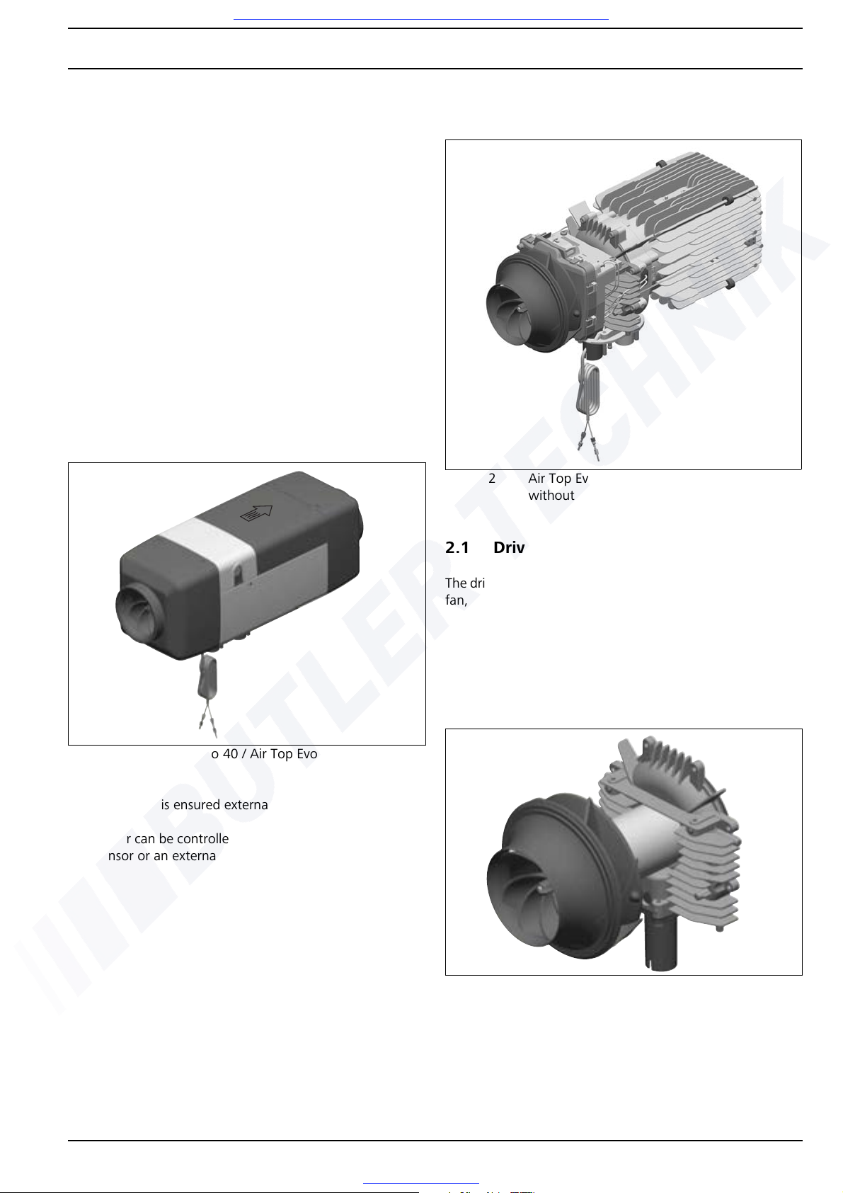
2.1 Drive unit
The drive unit consists of the drive motor, the combustion air
fan, the heating air fan and the intake housing.
The combustion air fan supplies the air required for the
combustion process from the combustion air inlet to the
evaporator mount.
The heating air fan transports the cold air from the cold air
inlet to the hot air outlet via the heat exchanger.
Fig. 201 Air Top Evo 40 / Air Top Evo 55 air heater
Fig. 202 Air Top Evo 40 / Air Top Evo 55 air heater
without housing
Fig. 203 Drive unit
Visit www.butlertechnik.com for more technical information and downloads.
www.butlertechnik.com
Page 10
General Description Air Top Evo 40 / Air Top Evo 55
202
2.2 Heat exchanger
The heat generated by combustion in the heat exchanger is
given off to the cold air transported by the heating air fan.
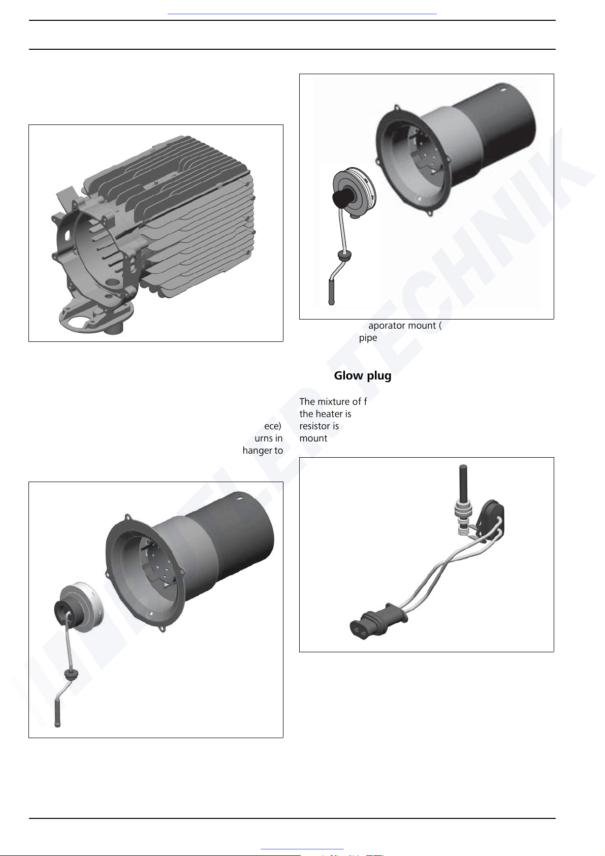
2.3 Evaporator mount with combustion pipe
The fuel is distributed via the metal fibre evaporator (fleece)
in the evaporator mount. The mixture of fuel and air burns in
the combustion chamber, thus causing the heat exchanger to
become hot.
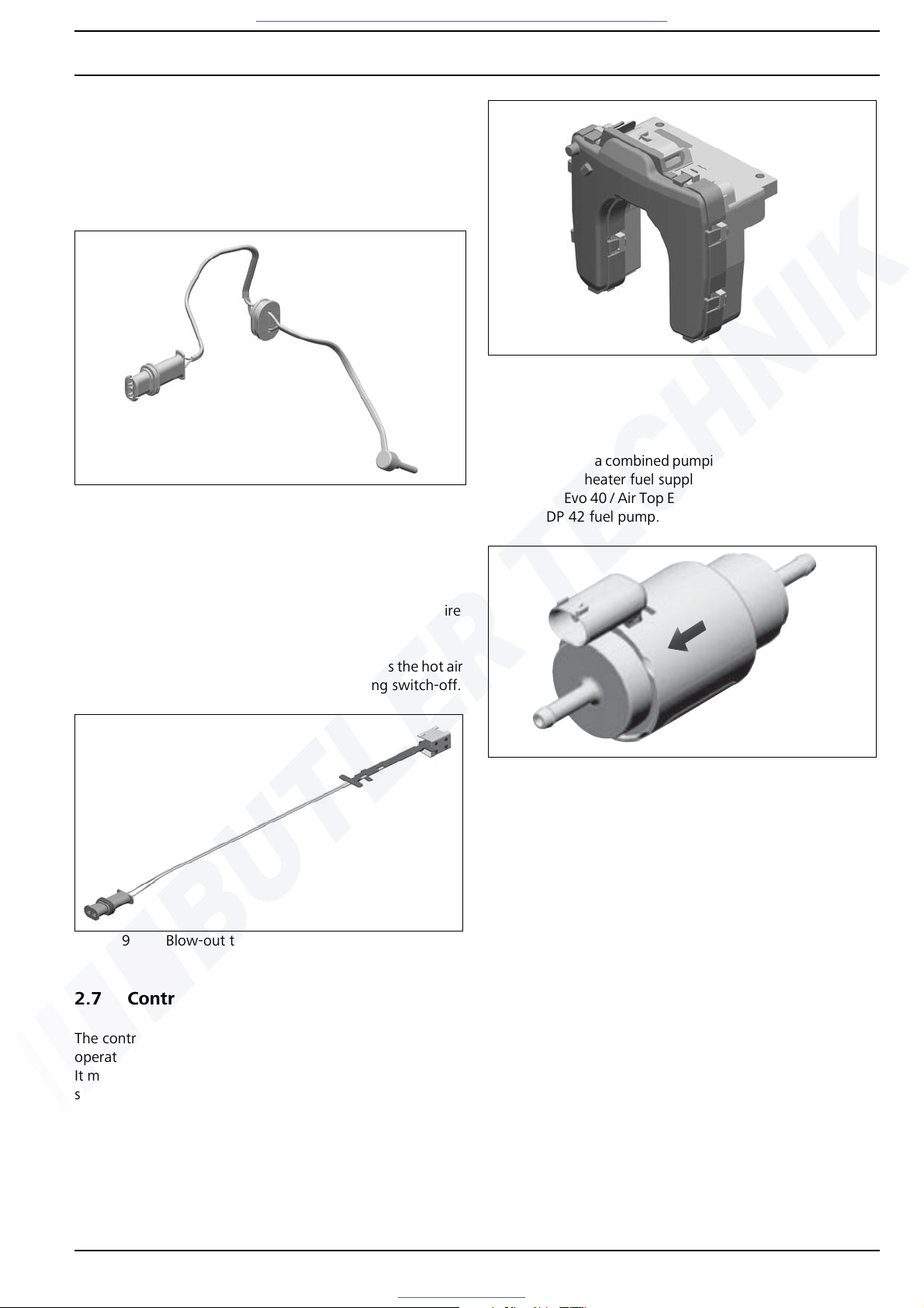
2.4 Glow plug
The mixture of fuel and air is ignited by the glow plug when
the heater is started. The glow plug designed as an electrical
resistor is positioned in the burner assembly (evaporator
mount with combustion pipe) on the side facing the flame.
Fig. 204 Heat exchanger
Fig. 205 Evaporator mount (diesel) and combustion
pipe
Fig. 206 Evaporator mount (petrol) and combustion
pipe
Fig. 207 Glow plug
Visit www.butlertechnik.com for more technical information and downloads.
www.butlertechnik.com
Page 11
Air Top Evo 40 / Air Top Evo 55 General Description
203
2.5 Exhaust temperature sensor
The exhaust temperature sensor is a low-resistance PTC resistor which changes its resistance in dependence on the temperature change of the exhaust gases. This change in
resistance is also used for flame monitoring.
2.6 Blow-out temperature sensor
The blow-out temperature sensor measures the temperatures in the fin area of the heat exchanger during the entire
heater operation.
The control unit evaluates the signal and regulates the hot air
outlet temperature and controls the overheating switch-off.
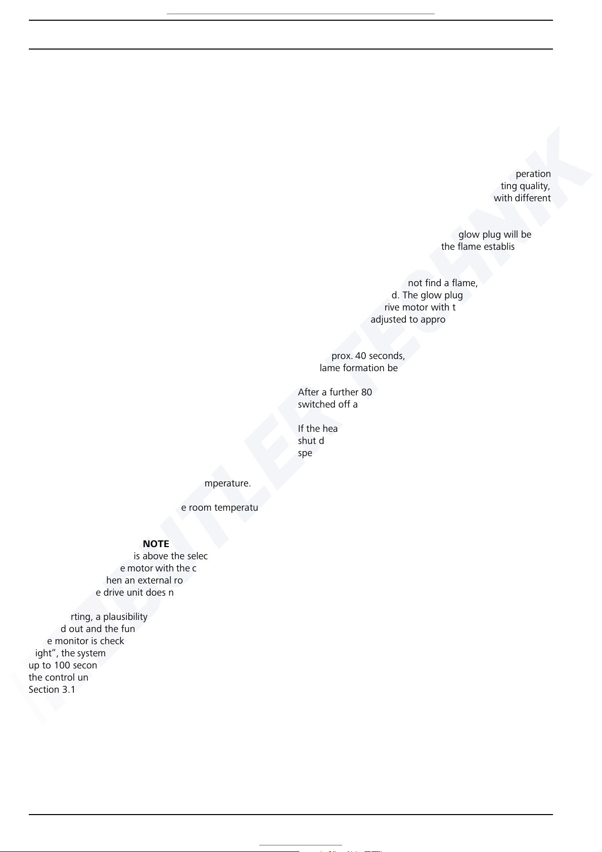
2.7 Control unit
The control unit is the central component for ensuring the
operating sequence.
It monitors the components, evaluates the signals of the sensors and regulates the heating mode.
2.8 Fuel pump
The fuel pump is a combined pumping, metering and shut-off
system for the heater fuel supply.
The Air Top Evo 40 / Air Top Evo 55 heaters must be operated
with the DP 42 fuel pump.
Fig. 208 Exhaust temperature sensor
Fig. 209 Blow-out temperature sensor
Fig. 210 Control unit
Fig. 211 DP 42 fuel pump
Visit www.butlertechnik.com for more technical information and downloads.
www.butlertechnik.com
Page 12
Function Description Air Top Evo 40 / Air Top Evo 55
301
3 Function Description
3.1 Control element
Air Top Evo 40 / Air Top Evo 55 can be activated either with
suitable control elements, e.g. rotary selector, combination
timer, or an Air Top Evo Multi Control (MC04).
Operation is described in the operating instructions of the respective control element.
The control element is used to switch the heater on and off,
to set the desired room temperature (between approx. 5 °C
and 35 °C) and the operating indicator.
The installed operating indicator is used
• as switch-on check,
• as a fault signal and
• as a service display.
Additional comfort functions (Eco, Normal, Plus and Ventilation) can be controlled with the Air Top Evo Multi Control
(MC04) control element.
NOTE
ADR operation:
After an ADR switch-off, the heater is in an ADR lock-out.
This is cancelled by switching the device off and then on
again.
3.2 Switching on
Switch on heater.
Set the control element to the required temperature.
The starting process begins when the room temperature is
below the setpoint temperature.
NOTE
If the room temperature is above the selected setpoint temperature, only the drive motor with the combustion and heating air fan runs. When an external room temperature sensor
is connected, the drive unit does not run.
Before starting, a plausibility test of the temperature sensors
is carried out and the function of the exhaust-temperature
flame monitor is checked. If the flame monitor now reports
“light”, the system will attempt to cool the flame monitor for
up to 100 seconds. If the flame monitor still reports “light”
the control unit will suffer a fault lock-out. Also see
Section 3.10, "Fault switch-off".
Start
When the heater is switched on the operating display will be
lit and the glow plug will be switched on (cycled). The drive
motor with the combustion and heating air fan is adjusted to
approx. 50 % of the maximum speed.
After approx. 40 seconds, the fuel pump is put into operation
and flame formation begins. To improve the starting quality,
the fuel pump and the drive unit are controlled with different
frequencies and speeds.
After a further 80 to 120 seconds the glow plug will be
switched off and the existence of the flame established.
Automatic restart
If the flame monitor does not find a flame, the starting procedure will be repeated. The glow plug will be switched on
again (cycled). The drive motor with the combustion and
heating air fan is adjusted to approx. 50 % of the maximum
speed.
After approx. 40 seconds, the fuel pump is put into operation
and flame formation begins.
After a further 80 to 120 seconds the glow plug will be
switched off and the existence of the flame established.
If the heater has again failed to ignite properly, the it will be
shut down using a fault slow down procedure at maximum
speed after approx. 240 seconds and will suffer a fault lockout.
NOTE
After restarting, a fault lock-out of the heater is carried out.
To reset the fault switch the heater off briefly (at least 2 seconds) and then on again.
3.3 Heating mode
Whilst the heater is operating the combustion gases pass
through the heat exchanger. In the process, the combustion
heat is given off to the walls of the heat exchanger, absorbed
by the cold air transported by the heating air fan and routed
into the vehicle interior.
The temperature of the cold air intake is measured by a room
temperature sensor in the control unit or an external room
temperature sensor. If the measured temperature is less than
is set on the control element, the heater output increases to
the maximum heating capacity.
To increase the burner service life in continuous operation,
the delivery capacity of the fuel pump is reduced for 10 seconds every 10 minutes.
Visit www.butlertechnik.com for more technical information and downloads.
www.butlertechnik.com
Page 13
Air Top Evo 40 / Air Top Evo 55 Function Description
302
In addition, the heating mode is briefly interrupted after every
8 hours and then automatically restarted in the same way as
for a control break. This ensures controlled combustion operation.
3.4 Control mode
In the control mode, the drive motor speed and the fuel
pump quantity are dependent on the heating capacity. The
glow plug is off.
3.5 Control break
After the temperature set on the control element has been
reached the heat output is reduced. The speed of the combustion and heating air fan and the pumping quantity of the
fuel pump are reduced.
If, at minimum heat output, the intake temperature set on
the control element is exceeded, the fuel pump is shut down
and the combustion process ended. To burn off the flame
properly, the drive motor speed falls after 20 seconds to partial load speed and then returns to the initial speed after
20 seconds, after which it falls to the control break speed in
approx. 90 seconds, where it remains for the entire control
break.
The control break speed is 0 if an external room temperature
sensor is used.
If the temperature set on the control element is dropped be-
low the room temperature sensor, the heater starts again.
NOTE
Changes to the setting on the control element are implemented by the control unit and heater after a delay.
3.6 Switching off
When the heater is switched off, the operating display on the
control element goes out. If no fuel has been transported yet
or if the heater is in the control break, the heater is switched
off immediately without a run-on period.
If the fuel transport has been started it is ended when the
heater is switched off. The heater is switched off using the
same method as the transition from control mode to control
break. The heater is then switched off automatically.
NOTE
It is permissible to switch on the heater again during the runon. In this case the run-on is completed and the heater is then
restarted.
3.7 Functions of Air Top Evo System
3.7.1 System design
The Air Top Evo 40 D and Air Top Evo 55 D heaters (diesel)
can be designed as a system with 2 heaters.
Here Unit 1 is defined as the master heater and Unit 2 as the
slave heater. The control element and an external room tem-
perature sensor (T) are connected to the master heater (see
wiring diagram in Figure Fig. 706). The slave heater is con-
nected as shown in the wiring diagram (see Fig. 707) . The
units communicate with each other via a serial bus system.
IMPORTANT
The use of an Air Top Evo system is not permitted for dangerous goods transports (ADRs)!
3.7.2 Installation/Commissioning
Installation
1. Installation of the heaters in accordance with Air Top Evo
40 / Air Top Evo 55 installation instructions
2. Ensure that the electrical connections are in accordance
with the wiring diagram (Fig. 706, Fig. 707)
3. Installation of control element and external room temperature sensor
NOTE
When the heaters are switched on, the system automatically
configures itself as master and slave.
3.7.3 Resetting Master/Slave System
In case of a power failure, the system will be reset to the original state (“Stand Alone”).
It is also possible to reset the system with the Webasto Thermo Test PC Diagnosis (from Version 2.13).
3.8 Heater functions when installed in ADR
vehicles
NOTE
Only applies to Air Top Evo 40 / Air Top Evo 55 heaters installed in vehicles for transporting dangerous goods (ADR).
If the heater is switched off using the control element the
slow down time remains unchanged.
A brief slow down time (max. 40 seconds) is started automatically if
• the vehicle’s engine is switched off
• a transport device is started.
The ADR switch-off can also be triggered by vehicle-specific
safety mechanisms.
Visit www.butlertechnik.com for more technical information and downloads.
www.butlertechnik.com
Page 14
Function Description Air Top Evo 40 / Air Top Evo 55
303
After an ADR switch-off, the control unit is in the "ADR lockout" position. For repeat start-up, the control element must
be set to "OFF" and the auxiliary drive signal or the vehiclespecific safety mechanism must no longer be active.
The battery isolation switch or the Emergency-Stop switch
may only be operated in case of danger, as the heater is
switched off without any run-on whatsoever (overheating is
possible).
3.10 Fault switch-off
Errors on the various heater components and faults in the
starting process and in heating mode are identified in the
control unit. For safety reasons, the fuel pump will be
switched off after all detected faults. The heater is switched
off and switches into the fault lock-out mode.
For details, see Chapter 5, "Troubleshooting".
3.10.1 Error monitoring
The overheating, incorrect start and flame abort errors are
counted and cause the heater to suffer a fault lock-out after
an error has occurred the maximum number of times.
The incorrect start counter is increased by 1 each time the
heater fails to start. If the incorrect start counter reaches its
maximum permissible value of 9, then the heater is in the
heater lock-out status.
The fault counter is increased by 1 for each malfunction for
which there is no separate counter. If the fault counter reach-
es its maximum permissible value of 5, then the heater is in
the heater lock-out status.
The overheating counter is increased by 1 each time the heater overheats. If the overheating counter reaches its maximum
value of 5, then the heater is in the heater lock-out status.
After a flame abort, a restart is automatically carried out. The
condition for a restart is that the heater was in the control
mode directly beforehand. During the restart the cycle repetition counter is increased by one. This process is repeated
until the heater either burns properly again or the maximum
value of 3 for the cycle repetition counter has been reached.
The flame abort counter FAZ is increased by 1 when the cycle
repetition counter ZWZ has reached the maximum value. If
the flame abort counter reaches its maximum value of 3 the
heater will go into the heater lock-out status.
Automatic reset:
Following each heater start-up, the cycle repetition counter is
set to 0. The fault counter is set to 0 after a fault-free
transition to the control mode and the flame abort counter,
overheating counter, false starting counter and cycle
repetition counter are set to 0 after (!) fault-free combustion
operation (20 min.).
Visit www.butlertechnik.com for more technical information and downloads.
www.butlertechnik.com
Page 15
Air Top Evo 40 / Air Top Evo 55 Function Description
304
3.10.2 Reset a fault switch-off
Certain errors result in the errors being added up in the error
memory. If the number of errors in the error memory has
exceeded a limit, the heater changes over to the heater lockout. The maximum number of errors in the error memory or
the error memory limit is defined by Webasto.
Cancel heater lock-out
The heater lock-out can be cancelled
– with the Webasto Thermo Test PC Diagnostics (WTT)
– or by switching on the heater.
Remove fuse F1 for at least 10 s.
Switch off heater.
Reinstall fuse F1.
Switch on heater.
Cancel permanent heater lock-out
Only for “OE” heater variants which are integrated in the vehicle bus system.
Unlocking is only carried out with the vehicle-specific computer diagnosis.
1. Switch on heater
2. An error has occurred and is detected by the control
unit as a fault
3. The error code is displayed via the control element
4. Any active heater lock-out is cancelled (as described
below)
4.1. The heater detects an error as a fault
4.2. Fault switch-off with subsequent fault lock-
out
4.3. The error code is displayed via the control
element
5. Switch off heater
6. Determine error cause (e.g. with or without error
code, visual inspection of fuses and connectors, etc.)
7. Eliminate error
8. Switch on heater
9. Fault lock-out unlocked
10. The heater switches into the control mode
Visit www.butlertechnik.com for more technical information and downloads.
www.butlertechnik.com
Page 16
Technical Data Air Top Evo 40 / Air Top Evo 55
401
4 Technical Data
Except where limit values are specified, the technical data listed in the table refer to the usual heater tolerances of ±10%
at an ambient temperature of +20 °C and at the rated voltage
and in rated conditions.
Electrical components:
The control unit, timer*, glow plug and control element are
designed for 12 V or 24 V.
The drive unit, fuel pump, exhaust temperature sensor and
external room temperature sensor are independent of voltage.
* not for ADR
Fuel for Air Top Evo 40 B / Air Top Evo 55 B (petrol):
The fuel specified by the manufacturer in accordance with
DIN EN 228 must be used.
Fuel for Air Top Evo 40 D / Air Top Evo 55 D (diesel/
PME):
The diesel fuel specified by the manufacturer in accordance
with DIN EN 590 must be used.
We know of no negative influences due to additives.
If fuel is extracted from the vehicle’s tank, follow the additive
instructions issued by the vehicle manufacturer.
If you change to low-temperature fuel, the heater must be
operated for approx. 15 minutes so that the fuel system is
filled with the new fuel.
The Air Top Evo 40 D / Air Top Evo 55 D unit is also approved
for operation with PME (bio-diesel) which complies with the
standard DIN EN 14214.
About table (Fig. 401): Values in brackets apply to the increased heating capacity which is activated for a limited time
during each start-up.
Heater Operation Air Top Evo 40B Air Top Evo 55B Air Top Evo 40 D Air Top Evo 55 D
Type test permit EMC: E1 03 5529 (Air Top Evo 40 / Air Top Evo 55)
Heater: E1 00 0385 (Air Top Evo 40)
Heater: E1 00 0386 (Air Top Evo 55)
Model Air heater with evaporation burner
Heat output Control range 1.7 to 3.5 (4.0) kW 1.7 to 5.0 (5.5) kW 1.5 to 3.5 (4.0) kW 1.5 to 5.0 (5.5) kW
Fuel Petrol
DIN EN 228
Diesel/Bio-Diesel
DIN EN 590
DIN EN 14214
Fuel consumption Control range
0.18 to 0.38 (0.43) kg/h
0.25 to 0.51 (0.58) kg/h
0.18 to 0.54 (0.59) kg/h
0.25 to 0.73 (0.80) kg/h
0.15 to 0.36 (0.41) kg/h
0.18 to 0.43 (0.49) kg/h
0.15 to 0.51 (0.56) kg/h
0.18 to 0.61 (0.67) kg/h
Rated voltage 12 V 12/24 V
Operating voltage range 10.5 to 16 V 10.5 to 16 V/20.5 to 31 V
Rated power consumption Control range 15 to 40 (55) W 15 to 95 (130) W 15 to 40 (55) W 15 to 95 (130) W
Permissible ambient
temperature:
Heater – Operation
– Storage
Fuel pump – Operation
– Storage
Rotary selector – Operation
– Storage
–40 °C to +40 °C
–40 °C to +85 °C
–40°C to +20°C (petrol), +30°C (diesel)
–40 °C to +85 °C
–40 °C to +75 °C
–40 °C to +85 °C
Permissible combustion air
intake temperature
–40 °C to +20 °C
Adjustment range for room
temperature
Control range +5 °C to +35 °C
Volume flow rate of hot air
against 0.5 mbar
max. 132 (140) m3/h max. 200 (220) m3/h max. 132 (140) m3/h max. 200 (220) m3/h
Heater dimensions Length: 423 ± 2 mm
Width: 148 ± 1 mm
Height: 162 ± 1 mm
Heater weight 5.9 kg
Fig. 401 Technical data Air Top Evo 40 / Air Top Evo 55
Visit www.butlertechnik.com for more technical information and downloads.
www.butlertechnik.com
Page 17

Air Top Evo 40 / Air Top Evo 55 Technical Data
402
Setpoint values:
12 V 24 V
Glow plug At 25 °C
Test current: < 5 mA
No marking
0.190 - 0.250 ohms
Green marking
0.740 - 0.940 ohms
Drive unit Outside < 6 ohms
Blow-out temperature sensor at 25 ºC 2,195 ohms
External temperature sensor at 25 ºC 10,000 ohms
Exhaust temperature sensor 2,160 ohms
Undervoltage switch-off
(triggering time > 20 s )
10,5 V 20.5 V
Overvoltage switch-off
(triggering time > 6 s )
16 V 31 V
Fig. 402 Setpoint values for resistance values of components
Visit www.butlertechnik.com for more technical information and downloads.
www.butlertechnik.com
Page 18
Troubleshooting Air Top Evo 40 / Air Top Evo 55
501
5 Troubleshooting
5.1 General information
If a malfunction occurs, a flashing code is displayed on the
operating indicator or a fault code F .. on the combination
timer.
In addition, the heater can be checked using a personal computer (see Webasto PC Thermo Test PC Diagnosis operating
manual).
IMPORTANT
Troubleshooting work demands precise knowledge of the
structure and theory of operation of the various components
and must be carried out by trained personnel only. The functional relationships are described in Chapter 2 and 3.
IMPORTANT
The troubleshooting guide is restricted to the localisation of
defective components.
The following fault causes should always be checked or a
fault should be excluded for the following reasons:
• Corrosion on connector
• Loose connection on connector
• Poor crimp contacts on plugs
• Corrosion on lines and fuses
• Corrosion on battery terminals
If you wish to check individual components, the electrical
plug connectors on the control unit must be disconnected.
Conduct a function test in the vehicle after rectifying each
fault.
A direct operation of the individual components (with voltage) is not permitted.
5.2 General error symptoms
The following table (Fig. 501) lists possible fault symptoms.
Error symptom Possible cause Remedy
Heater cuts out automatically No combustion after starting and restarting
Operating display flashes
Switch heater off and then on again
Flame extinguishes during operation
Operating display flashes
Switch heater off and then on again
Heater overheated
Operating display flashes
Check the hot air guide for free passage, allow the heater to cool down, then briefly
switch the heater off and then on again
Vehicle voltage too low
Operating display flashes
Charge battery
Switch heater off and then on again
Heater emits black smoke Combustion air and/or exhaust system
blocked
Check that the combustion air and exhaust
systems are clear
Fig. 501 General error symptoms
Visit www.butlertechnik.com for more technical information and downloads.
www.butlertechnik.com
Page 19

Air Top Evo 40 / Air Top Evo 55 Troubleshooting
502
5.3 Error symptoms during function
The following table (Fig. 502) lists the possible error symptoms in the order in which they may occur during operation.
In the event of a fault, the error is to be located using this table and rectified. It is important that the error symptom is correctly identified.
If the error symptom is not included in this table or if the fault
is not found under the specific error symptom heading, in an
emergency you can contact our technicians on our service
hotline.
NOTE
Every fault is indicated by the flashing LED on the control element after the slow down time has finished. If the other
components are OK, a defective control unit may be the
cause of all the faults.
There are states which are equivalent to faults.
Error symptom Occurrence Possible causes
No start and no illumination of the LED
on the control element
immediate Incorrect cabling, defective fuse
No start but LED is lit immediate The unit immediately goes into a control break when
switched on; the control break speed is 0 rpm when an
external temperature sensor is used.
Fig. 502 Error symptoms during function
Visit www.butlertechnik.com for more technical information and downloads.
www.butlertechnik.com
Page 20

Troubleshooting Air Top Evo 40 / Air Top Evo 55
503
5.4 Fault code displayed in control element
If serious malfunctions, such as overheating or failure to start,
occur with increasing frequency, then the heater is
permanently locked out and can only be returned to
operation following repairs by Webasto-trained
professionals.
When equipped with a combination timer, a fault code
output appears on the display after a malfunction occurs until
the heater malfunction has been eliminated.
In case of equipment with a rotary selector or an Air Top Evo
Multi Control the fault code is displayed by means of a
flashing operating indicator after a malfunction occurs .
After five short signals, the long flashing pulses are counted.
The flashing pulses match the number in the table below (e.g.
F 04 = 4 long flashing pulses).
NOTE
For equipment with combination timer:
Fault codes F 01 to max. F 15 are displayed.
After this the faults are displayed with "- -".
Fault
code
Fault (group) Additional information during PC di-
agnostic
Troubleshooting
F 00 Control unit defective/
heater lock-out/
internal room temperature sensor
defective
01 Control unit error
81 EOL checksum error
11 Incorrectly coded control unit or incorrect
heater (fuel type) installed (the heater will not
work if this error occurs)
91 Neutrally coded or disabled control unit
(the heater will not work if this error occurs)
92 Maintain command failed (no operation if
fault occurs)
18 Customer bus defective
Replace control unit
07 Heater lock-out active Delete heater lock-out:
Switch on unit and remove fuse.
Reinstall fuse after more than 2 s and switch
on unit again
F 01 No start/no flame formation 02 Even after the restart, no flame has
formed
82 No start in test
83 Maximum feed rate exceeded
Check fuel supply
(tank empty, lines blocked).
Check exhaust temperature sensor for
deposits from outside through exhaust fitting
and clean carefully if necessary.
Check evaporator mount and replace if
necessary.
F02 Flame abort 03 The flame has gone out during operation
and has not reformed after a restart attempt
Check fuel supply
(tank empty, lines blocked).
Check exhaust temperature sensor for
deposits from outside through exhaust fitting
and clean carefully if necessary.
Check evaporator mount and replace if
necessary.
F 03 Undervoltage or overvoltage 84 The voltage was less than 10.5 V or 20.5
V for longer than 20 seconds
04 The voltage was more than 16 V or 32 V
for longer than 6 seconds
F 04 Premature flame detection 05 The exhaust temperature sensor
recognised a flame before combustion had
started
Check exhaust temperature sensor and
replace if necessary.
Fig. 503 Faults and error remedies (Page 1 of 2)
Visit www.butlertechnik.com for more technical information and downloads.
www.butlertechnik.com
Page 21

Air Top Evo 40 / Air Top Evo 55 Troubleshooting
504
F 05 Not available
F 06 Not available
F 07 Fuel pump defective 88 Open circuit in fuel pump Check electrical wiring and fuel pump and
replace if necessary
08 Short circuit in fuel pump
F 08 Open circuit/short circuit/
overloading/blockage in drive motor
09 Short circuit in drive motor
89 Open circuit in drive motor
15 Blocking guard in drive motor
95 Overload protection in drive motor
Eliminate cause of blockage/sluggishness
Check magnets of heating air fan and replace
drive unit (drive motor with combustion and
heating air fan) if necessary
F 09 Glow plug defective 19 Short circuit in glow plug
99 Open circuit in glow plug
Check glow plug and replace if necessary.
F 10 Overheating 06 Heater overheated - blow-out
temperature sensor
5B Heater overheated - PCBs - temperature
sensor
17 Temperature gradient exceeded - blow-
out temperature sensor
5C Temperature gradient exceeded - PCBs -
temperature sensor
Find and eliminate cause of overheating in
hot air guide.
Possible causes:
Pressure loss too high, line kinked, air outlet
closed, soiling of blow-out temperature
sensor
F 11 Not available
F 12 Not available
F 13 Not available
F 14 Blow-out temperature sensor
defective
1B Short circuit in blow-out temperature
sensor
AB Open circuit in blow-out temperature
sensor
Check blow-out temperature sensor and
replace if necessary.
F 15 Not available
F 16 Exhaust temperature exceeded 4F Upper limit of exhaust temperature
exceeded
Check free through-flow of combustion air
and exhaust system, check CO
2
setting, clean
soot from heat exchanger if necessary
F 17 Exhaust gas temperature sensor
defective
1A Short circuit to ground in exhaust
temperature sensor
9A Open circuit in exhaust temperature
sensor
Replace exhaust temperature sensor
F 18 Setpoint generator defective 9B Open circuit or short circuit to +Ub in
setpoint generator
Check wiring and replace control element if
necessary
F 19 Plausibility of sensors incorrect 93 Plausibility check not passed Check exhaust temperature sensor/blow-out
temperature sensor for plausibility and
replace defective sensor
Fault
code
Fault (group) Additional information during PC di-
agnostic
Troubleshooting
Fig. 503 Faults and error remedies (Page 2 of 2)
Visit www.butlertechnik.com for more technical information and downloads.
www.butlertechnik.com
Page 22

Troubleshooting Air Top Evo 40 / Air Top Evo 55
505
5.5 Maintenance display in control element
The maintenance signal is displayed when an operating
period of more than 3,000 operating hours has been reached
or the heater is in a restricted operating mode.
In case of restricted operation, either the automatic altitude
adjustment or the external room temperature sensor
(optional) may be defective. The heater can continue to be
operated, however with a considerable reduction in comfort
in some cases.
The heater should be inspected by trained professionals as
soon as possible.
The maintenance signal is displayed with equipment with a
rotary selector or an Air Top Evo Multi Control (MC04) by
means of flashing of the operating indicator for 60 seconds
each time the heater is started. Flashing signal 1 second on,
1 second off.
With equipment with combination timer, "- -" appears on the
display.
Visit www.butlertechnik.com for more technical information and downloads.
www.butlertechnik.com
Page 23

Air Top Evo 40 / Air Top Evo 55 Functional Checks
601
6Functional Checks
6.1 General information
This section describes the tests conducted on the heater
when it is installed and not installed to verify that it is in working order.
WARNING
The heater must not be operated in enclosed areas such as
garages and workshops without an emissions extraction system.
6.2 Required test and measuring equipment
The test and measuring equipment must be calibrated and
proof of measuring certificates must be available.
Digital multimeter
Testing of electrical resistance [ohms], electrical continuity
0.1 ohms
Test current < 5 mA
Voltage source, adjustable
Measuring of electrical voltage [V]
10 - 30 V
30 A
CO
2
measuring unit
Testing of CO
2
value [vol. %]
Maximum ± 0.3 vol. %
Heater test bench *1)
Heater function test
Regarding contact Webasto heater test bench: International
Technical Support - International Hotline:
hotline.wt@webasto.com
PC (personal computer)
Webasto Diagnosis Adapter incl. software
Diagnosis Adapter ID No. 9009064_ is available from
Webasto.
Display of fault memory, operating data and control unit information.
Reference heaterAir Top Evo 40 / Air Top Evo 55
The reference heater must be subjected to continual operating checks.
*1)
The following schematic diagram shows the components
necessary for operating a heater.
Application-specific interfaces must be taken into account. A
calibrated fuel pump, which is subjected to continual
operating checks, must be used for testing. The technical
requirements are contained in the Webasto product
documentation. It is preferable to use Webasto components.
Particular attention must be paid to work and occupational
safety.
Fig. 601 Components required for operating a heater
1. Rotary selector
2. Electrical vehicle interface
3. Heater fuse
4. Hot air outlet
5. Hot air outlet hose
6. Fuel pump
7. Fuel filter
8. Fuel standpipe
9. Fuel tank
10. Fuel line
11. Exhaust pipe
12. Combustion air intake
pipe
13. Cold air inlet grille
14. Air Top Evo Multi
Control (MC04) control
element
15. Combination timer
Visit www.butlertechnik.com for more technical information and downloads.
www.butlertechnik.com
Page 24

Functional Checks Air Top Evo 40 / Air Top Evo 55
602
6.3 Settings
6.3.1 Factory settings
The heater is set at the factory, based on an altitude of 0 m
above sea level, to a specified nominal CO
2
value in accordance with Section 6.3.2.
When used at altitudes above sea level, a higher CO
2
content
in the exhaust gas results.
This increased CO
2
content can be corrected to the nominal
value with a late CO
2
adjustment.
No setting/correction is necessary for heaters with automatic
altitude compensation!
6.3.2 Adjusting CO2 content
The CO2 content in the emissions is set using the temperature
selector on the control element. In the process, activate any
heating mode (Eco, Normal or Plus) with the Air Top Evo
Multi Control (MC04) control element.
IMPORTANT
The heater must be switched off.
1. Connect the CO
2
line to minus.
2. Turn the adjustment knob on the control element to the
centre position. The heater will start and go automatically to partial load mode.
NOTE
If the heater can be adjusted the operating indicator will flash
as if the control unit has suffered an error.
Diesel units:
3. Adjust the CO
2
value by turning the adjustment knob.
Turning it anticlockwise will reduce the CO
2
value, whilst
turning it clockwise will increase it. The CO
2
content
must be set in accordance with Table Fig. 603 at partial
load depending on the altitude.
Petrol units:
3. The CO
2
content may only be set with the unit at oper-
ating temperature. The unit must be operated for at least
8 minutes for this purpose.
Then the CO
2
content must be set in accordance with
Table Fig. 603 at partial load depending on the altitude.
Diesel and petrol units:
4. If the CO
2
value is in the permissible range, disconnect
the CO
2
line from minus. This saves the setting.
NOTE
The heater will now run in the normal mode again and can
be switched off in the accustomed manner using the control
element.
Fig. 602 Heater test bench
Air Top Evo 40
Air Top Evo 55
Petrol
12 V
Air Top Evo 40
Air Top Evo 55
Diesel
12 V/24 V
0 m above sea level 5,6 6,3
500 m above sea level 6,0 6,7
1,000 m above sea level
6,3 7,1
1,500 m above sea level
6,7 7,6
Fig. 603 Nominal values for CO
2
content in exhaust gas
[vol. %]
Visit www.butlertechnik.com for more technical information and downloads.
www.butlertechnik.com
Page 25

Air Top Evo 40 / Air Top Evo 55 Functional Checks
603
6.4 Tests of individual components
IMPORTANT
For function tests always disconnect the connection between
the control unit and the component to be tested.
NOTE
If a fault occurs which cannot be detected with this procedure, the unit/component must be sent in to the Webasto
Warranty Department.
NOTE
Damage caused by soiling will not be recognised by
Webasto!
Graph legend
(1) Replace component. Send defective components (not
entire heater) to Webasto within warranty period.
(2) Replace component and continue.
(3) Replace heater. Send defective heater to Webasto within
warranty period.
(4) Continue.
Visit www.butlertechnik.com for more technical information and downloads.
www.butlertechnik.com
Page 26

Functional Checks Air Top Evo 40 / Air Top Evo 55
604
6.4.1 Burner component assembly
See Fig. 907, Item 3 and Item 7
2
4
1
1
Burner assembly
(evaporator mount with
combustion pipe)
Evaporator mount or combus-
tion pipe mechanically dam-
aged?
no
yes
Is fuel pipe freely passable?
no
Check function on heater
test bench
Can CO
2
value be adjusted
with to the correct value?
no
yes
Procedure Test or meas-
uring equipment
Visual
Visual inspection
Blow through
Conduct function
test with refer-
ence heater.
Adjust the refer-
ence unit after
5minutes to CO
2
nominal value in
accordance with
graphic on site,
install burner assembly to be evaluated in reference
unit and measure
CO
2
value after 5
minutes of operation.
– Heater test
bench
–CO
2
measur-
ing unit
–Webasto Di-
agnosis
Adapter
– PC (personal
computer)
– Reference
heater
Visit www.butlertechnik.com for more technical information and downloads.
www.butlertechnik.com
Page 27

Air Top Evo 40 / Air Top Evo 55 Functional Checks
605
6.4.2 Resistance test of exhaust temperature sensor
See Fig. 907, Item 10.
During the test with a digital multimeter, the exhaust temperature sensor is to have the following values:
Resistance at 20 °C: 2,160 ± 3.2 ohms
Test current: < 5 mA
1
1
1
4
Exhaust temperature sen-
sor
Procedure Test or meas-
uring equipment
Visual
Visual inspection
Visual inspection
Resistance measurement
Digital multimeter
no
yes
no
yes
no
yes
Cables damaged?
Ceramic broken?
Resistance outside
2,160 ± 3,2 ohms?
Visit www.butlertechnik.com for more technical information and downloads.
www.butlertechnik.com
Page 28

Functional Checks Air Top Evo 40 / Air Top Evo 55
606
6.4.3 Heating air fan component
See Fig. 903, Item 1
6.4.4 Glow plug component
See Fig. 907, Item 8
NOTE
The resistance test must be carried out with an ohmmeter
suitable for small resistance values.
A resistance test with a simple digital multimeter is too inaccurate to find the precise values. A new glow plug can be
measured to act as a reference.
The glow plug should have the following values in the test:
2
2
Heating air fan
Heating air fan mechanical-
ly damaged?
no
yes
Procedure Test or meas-
uring equipment
Visual
Visual inspection
– Deformation
–Magnets
present
– Locking lug
broken
Glow plug: 12 V
(no marking)
24 V
(green marking)
Resistance at
25 °C:
Test current:
0.190 - 0.250 ohms
< 5 mA
0.740 - 0.940 ohms
< 5 mA
Visit www.butlertechnik.com for more technical information and downloads.
www.butlertechnik.com
Page 29

Air Top Evo 40 / Air Top Evo 55 Functional Checks
607
1
2
2
4
1
Glow plug
Contacts detached?
no
yes
Procedure Test or meas-
uring equipment
Visual
Visual inspection
Visual inspection
Visual inspection
Resistance measurement
Digital multimeter
no
yes
no
yes
no
yes
Cables damaged?
Ceramic broken?
Resistance
outside
0.190 - 0.250 ohms (12 V)
0.740 - 0.940 ohms 24 V)?
Visit www.butlertechnik.com for more technical information and downloads.
www.butlertechnik.com
Page 30

Functional Checks Air Top Evo 40 / Air Top Evo 55
608
6.4.5 Drive unit component
See Fig. 903, Item 2
1
1
1
4
1
1
Drive unit
Externally damaged?
no
yes
Procedure Test or meas-
uring equipment
Visual
Visual inspection
Continuity measurement
Digital multime-
ter
Drive motor startup
Voltage source
Subjective test
IMPORTANT
Ensure correct polarity (+)/(–)
(–) = black
(+) = red
no
yes
no
yes
no
yes
Resistance > 6 ohms?
Start at 10 V?
Bearing noises?
no
yes
Installation of component
in unit => short circuit to metal
parts (heat exchanger etc.)?
Visit www.butlertechnik.com for more technical information and downloads.
www.butlertechnik.com
Page 31

Air Top Evo 40 / Air Top Evo 55 Functional Checks
609
6.4.6 Blow-out temperature sensor component
See Fig. 903, Item 9
During the resistance test with a digital multimeter, the blowout temperature sensor must have values in accordance with
the following chart:
Fig. 604 Characteristic resistance value of a PT 2000
blow-out temperature sensor in the
temperature range 10 °C to 30 °C
Resistance in ohms
Temperature in °C
1
1
1
4
1
Blow-out temperature sen-
sor
Contacts detached?
no
yes
Procedure Test or meas-
uring equip-
ment
Visual
Visual inspection
Visual inspection
Visual inspection
Resistance measurement
Digital multimeter
no
yes
no
yes
yes
Cables damaged?
Connector damaged?
Resistance outside
2-2.5 kohms?
no
Visit www.butlertechnik.com for more technical information and downloads.
www.butlertechnik.com
Page 32

Functional Checks Air Top Evo 40 / Air Top Evo 55
610
6.4.7 Control unit component
See Fig. 701 and Fig. 903, Item 4
2
1
4
Control unit
Externally damaged?
no
yes
Procedure Test or meas-
uring equipment
Visual
Visual inspection
–Housing
broken?
– All clips
engaged?
– Clips torn?
Conduct function
test with the reference unit,
mount the control
unit to be tested
in the reference
heater and con-
duct the function
test again
– Heater test
bench
– PC (personal
computer)
–Webasto Di-
agnosis
Adapter
– Reference
heater
no
yes
Fault-free operation in ref-
erence heater?
Visit www.butlertechnik.com for more technical information and downloads.
www.butlertechnik.com
Page 33

Air Top Evo 40 / Air Top Evo 55 Functional Checks
611
6.4.8 Heater component
Complete heater
Testing of all electrical com-
ponents
Description Procedure Test or meas-
uring equipment
Remove upper shell from
heater and pull component
connector off control unit
PCB. Wire colours of individual components:
Glow plug (yellow),
Drive unit (black/red),
Exhaust temperature sensor
(white)
Replace component and
continue
Resistance measurement
Digital multimeter
Replace component and
continue
Resistance measurement
Digital multimeter
Replace component and
continue
Resistance measurement
Digital multimeter
Replace component and
continue
Resistance measurement
Digital multimeter
no
yes
Glow plug:
Resistance outside
0.190 - 0.250 ohms (12 V)
0.740 - 0.940 ohms (24 V)?
Drive unit: Resistance
>6ohms?
Blow-out temperature sensor:
Resistance outside
2-2.5 kohms?
no
yes
no
yes
no
yes
Exhaust gas temperature sen-
sor resistance outside
2,160 ± 3.2 ohms?
Reading out control unit
data:
Burning hours, number of
starts, errors
Summarise control unit
data and save
Visit www.butlertechnik.com for more technical information and downloads.
www.butlertechnik.com
Page 34

Functional Checks Air Top Evo 40 / Air Top Evo 55
612
Check function on heater
test bench
Description Procedure Test or measuring
equipment
Replace component and continue
Continuity measurement
Function test
Digital multimeter
– Heater test bench
–CO
2
measuring unit
– PC (personal compu-
ter)
– Webasto Diagnosis
Adapter
– Reference heater
Function test
Control unit test in refer-
ence heater
Fault-free operation in ref-
erence heater?
no
yes
no
yes
Fault-free operation?
All tested electrical
components are OK
Installation of component
in unit => short circuit to metal
parts (heat exchanger
etc.)?
no
yes
Visit www.butlertechnik.com for more technical information and downloads.
www.butlertechnik.com
Page 35

Air Top Evo 40 / Air Top Evo 55 Functional Checks
613
2
2
3
2
C
Reinstallation of control
unit in heater to be tested
Description Procedure Test or measur-
ing equipment
Conduct function test
with reference heater.
Adjust the reference unit
after 5 minutes to CO
2
nominal value in accordance with graphic on site,
install burner assembly to
be evaluated in reference
unit and measure CO
2
value after 5 minutes of
operation.
Function test
CO
2
measurement
– Heater test
bench
–CO
2
measuring
unit
– PC (personal
computer)
– Webasto Diag-
nosis Adapter
– Reference
heater
CO2 value
within tolerance?
Set CO
2
value in permissible
range
Checking burner assembly
in reference heater
CO
2
value adjustable in tol-
erance in reference heater?
no
yes
CO
2
value
adjustable?
no
yes
no
yes
Visit www.butlertechnik.com for more technical information and downloads.
www.butlertechnik.com
Page 36

Wiring Diagrams Air Top Evo 40 / Air Top Evo 55
701
7 Wiring Diagrams
7.1 General information
The Air Top Evo 40 / Air Top Evo 55 heaters can be operated
with the rotary selector, a combination timer or the Air Top
Evo Multi Control (MC04) control element.
The wiring diagrams (Fig. 702 to Fig. 707) show the possible
circuits for 12 or 24 V.
• Rotary selector and vehicle fan
• ADR operation with rotary selector
• Combination timer and electrical battery isolation switch
• Air Top Evo Multi Control (MC04) control element
• “Master heater“ with rotary selector
•“Slave heater“
Fig. 701 shows the plug assignment on the control unit.
Fig. 708 shows the schematic connection of the combination
timer.
Fig. 709 shows the schematic connection of the Air Top Evo
Multi Control (MC04) control element.
See Section 7.2 for wiring diagram legends.
IMPORTANT
The use of force when pressing on the connectors can de-
stroy the mechanical coding, i.e. the reverse polarity protection or the correct assignment of the connection is no longer
ensured. This can then result in considerable damage to the
heater.
Fig. 701 Connector assignment on control unit
X8
X1
X4
X5 X7
X6
X3
X2
X1 = Drive motor connection
X2 = Glow plug connection
X3 = Blow-out temperature sensor connection
X4 = Fuel pump connection
X5 = Connection of external temperature sensor
X6 = D+ and auxiliary drive unit connection
X7 = Heater wiring harness connection
X8 = Exhaust temperature sensor connection
Visit www.butlertechnik.com for more technical information and downloads.
www.butlertechnik.com
Page 37

Air Top Evo 40 / Air Top Evo 55 Wiring Diagrams
702
Fig. 702 Wiring diagram for Air Top Evo 40 and Air Top Evo 55, 12 V/24 V with rotary selector and vehicle fan
Fig. 703 Wiring diagram for Air Top Evo 40 and Air Top Evo 55, 24 V for ADR operation with rotary selector
Visit www.butlertechnik.com for more technical information and downloads.
www.butlertechnik.com
Page 38

Wiring Diagrams Air Top Evo 40 / Air Top Evo 55
703
Fig. 704 Wiring diagram for Air Top Evo 40 and Air Top Evo 55, 12 V/24 V with 1531 combination timer and electr.
battery isolation switch
Fig. 705 Wiring diagram for Air Top Evo 40 and Air Top Evo 55, 12 V/24 V with Air Top Evo MultiComfort (MC04) control
element. Wiring harness available as an option.
Visit www.butlertechnik.com for more technical information and downloads.
www.butlertechnik.com
Page 39

Air Top Evo 40 / Air Top Evo 55 Wiring Diagrams
704
Fig. 706 Wiring diagram for Air Top Evo 40 and Air Top Evo 55 "Master heater", 12 V/24 V with rotary selector
Fig. 707 Wiring diagram for Air Top Evo 40 and Air Top Evo 55 "Slave heater", 12 V/24 V
X3/X4/X5/X6/X8
X1/X2
X7
X15
X13
910
12
4
11
1
8
6
2
12
M
M1
12
X2
E
12
B3
X3
12X412
X5
4
1
3
ws 0,5mm²
bl 0,5mm²
sw 0,5mm²
rt 0,5mm²
A1
1
ge
0,5mm²
B2
S3
gr/rt
0,5mm²
0,5mm²
F1
F3
A2
31
X9(c)
sw
rt
gege
wsws
7
5
X15a
br
rt
rt 0,5mm²
X7
br 0,5mm²
1
3
5
7
9
11
1
2
2
1
15
rt
rt
2
1
3
4
H1
X9(a)
S1
1
2
X6
X9
1
2
3
4
3
30
ge/bl
0,5mm²
12
B5
X8
ws
X1
2
2
3
5
1
2
BOSCH
X16
X17
sw
0,6mm²
sw
0,6mm²
X13
Y1
B4
X11
12
6
12
X16
X17
bl
0,5mm²
br
0,5mm²
ws
3
X6
1
2
X3/X4/X5/X6/X8X1/X2
X7
X13
910
12
4
11
7
8
6
2
ge
0,5mm²
F1
A2
15
30
31
1
5
br
rt
X7
1
3
5
7
9
11
1
2
2
1
ge/bl
0,5mm²
12
M
M1
12
X2
E
12
B3
X3
12X412
X5
A1
B2
sw
rt
gege
wsws
12
B5
X8
ws
X1
X9
67769 A
X10
1
2
3
4
br 0,5mm²
ge 0,5mm²
ge/rt 0,5mm²
rt 0,5mm²
1
4
2
3
X9
ge/bl 0,5mm²
4
3
1
2
X10
5
1
2
BOSCH
X16
X17
sw
0,6mm²
sw
0,6mm²
X13
Y1
B4
X11
12
6
12
X16
X17
bl
0,5mm²
br
0,5mm²
ws
Visit www.butlertechnik.com for more technical information and downloads.
www.butlertechnik.com
Page 40

Wiring Diagrams Air Top Evo 40 / Air Top Evo 55
705
Fig. 708 Connection diagram fir Air Top Evo 40 and Air Top Evo 55 with 1531 combination timer
Fig. 709 Connection diagram for Air Top Evo 40 and Air Top Evo 55 with Air Top Evo
Multi Control (MC04) control element
1. 1531 combination timer
2. grey: Terminal 58
3. black: Terminal 15
4. red: Terminal 30
5. brown: Terminal 31
6. Wiring harness adapter
1. Air Top Evo Multi Control (MC04) control element
2. Observe coloured markings
3. Optional connection for:
- Telestart/Thermo Call (12 V only)
- Webasto Thermo Test PC Diagnosis
4. Heater wiring harness (available as an option)
Visit www.butlertechnik.com for more technical information and downloads.
www.butlertechnik.com
Page 41

Air Top Evo 40 / Air Top Evo 55 Wiring Diagrams
706
7.2 Legend for wiring diagrams
Cable cross-sections Cable colours
< 7.5 m 7.5 - 15 m
0.75 mm2 1.0 mm2
1.0 mm
2
1.5 mm2
1.5 mm2 2.5 mm2
2.5 mm2 4.0 mm2
4.0 mm
2
6.0 mm2
Abbreviation Colour
bl blue
br brown
ge yellow
gn green
gr grey
or orange
rt red
sw black
vi violet
ws white
Item Description Comment
A1 Heater Air Top Evo 40 / Air Top Evo 55
A2 Control unit Control unit 1580
B2 Room temperature
sensor
Internal
B3 Blow-out temperature
sensor
Overheating guard
B4 Room temperature
sensor
External
B5 Exhaust temperature
sensor
Overheating protection/flame
monitor
EGlow plug
F1 Fuse 15 A (24 V)
or 20 A (12 V)
Flat fuse SAE J 1284
F2 Fuse 4 A Blade fuse SAE J 1284,
not contained in wiring harness
F3 Fuse 1 A Flat fuse SAE J 1284
F4 Fuse 4 A Blade fuse SAE J 1284,
not contained in wiring harness
F5 Fuse Value in [A] to be selected
depending on line cross-section
H1 LED green (in Item S1) Operating Indicator
H2 LED red (in Item P) Lighting of immediate heat
button, operating indicator
H3 Display (in Item P) Heating symbol, operating
indicator
H4 Light bulb/LED
(in Item P and S)
Display and button lighting
H5 Light bulb/LED Switch-on check for pumping
device,
max. 500 mA
KRelay
with free-wheeling
diode
for vehicle fan,
max. 500 mA
M1
Drive motor
Combustion and heating air fan
M3 Motor Vehicle fan
P Combination timer
1531
Timer and temperature selector
Item Description Comment
S Air Top Evo Multi Con-
trol (MC04) control element
On/Off switch, selector switch
for additional functions and
temperature selector
S1 Heater-control rotary
selector
On/Off switch and temperature
selector
S2 Switch Ventilation
S3 Switch CO
2
setting
S4 Push button External instant heat button
S5 Switch Pumping devices/ auxiliary
drive
S6 Switch, single or two-
pin
Isolation switch
S7 Battery isolation switch Electronically controlled isolat-
ing switch, max. 500 mA
V1/V2 Blocking diode min. 500 mA
X1-X8 Plug connector on Item A2
X9 (a) Plug connector on Item S or S1
X9 (b) Plug connector on Item S or S2
X9 (c) Plug connector W bus, optional connection of
Telestart (12 V) or Thermo Call
X1-X11 Plug connector In heater on control unit
X13 Plug connector to Item Y1
X14 Plug connector to Item P
X15 Plug connector to Item S3
X16 Plug connector Connection of wiring harness
DP 42
X17 Plug connector Connection of wiring harness
DP 42
Y1 Fuel pump DP 42
Y2 Solenoid valve/pump Pumping devices/auxiliary
drive, max. 500 mA
Visit www.butlertechnik.com for more technical information and downloads.
www.butlertechnik.com
Page 42

Wiring Diagrams Air Top Evo 40 / Air Top Evo 55
707
Note numbers
(1) With plus from Terminal 15/75 to Connection 10:
Continuous operation with immediate heating as long as
ignition is switched on.
(2) All heater variants: W bus PC Diagnostics connection.
Heater variants with Air Top Evo Multi Control (MC04)
control element and combination timer:
Thermo Call connection
Telestart connection (12 V only).
Master heater variant: Slave heater connection (ye/bl
wire).
Prefabricated cable is contained in slave delivery scope.
(3) CO
2
setting.
(4) If the connection is made to Terminal 30, continuous
heating is possible with the ignition switched off!
In this case, no connection may be made to Terminal 15/
75!
(5) Grey and purple wires are required for ADR function.
On non-ADR vehicles the wire ends must be insulated
and tied back.
(6) External room temperature sensor (optional).
NOTE: The sensor is mandatory for the Master heater
variant.
(7) Fuse present in vehicle.
(8) Pin 7 "Boost" only for Ambulance heater variant (door
contact on Terminal 31).
(9) Connection necessary when using 1531 combination
timer in ADR vehicles.
(10) Wiring harness adapter is available as an option.
Visit www.butlertechnik.com for more technical information and downloads.
www.butlertechnik.com
Page 43

Air Top Evo 40 / Air Top Evo 55 Service Work
801
8 Service Work
8.1 General information
This section describes the servicing work that can be carried
out on the heater when it is installed.
8.2 Work on heater
Disconnect the main power cable from the vehicle’s battery
before carrying out any work on the heater. The main battery
power must not be disconnected whilst the heater is operating or slowing down as this could result in the heater overheating and the overheating guard thus being tripped.
If you wish to carry out extensive repair work on the heater,
it may be a good idea to remove it completely.
When the heater is removed and reinstalled, the base seal
must be replaced.
With repairs which make it necessary to change the installation location, the installation instructions concerned and the
vehicle-specific installation suggestion of the heater must be
observed.
8.3 Work on vehicle
IMPORTANT
A temperature of 85 °C must not be exceeded in the vicinity
of the heater in any circumstances (for example when com-
pleting painting work on the vehicle).
8.4 Heater test operation
WARNING
The heater must not be operated in enclosed areas such as
garages and workshops without an emissions extraction system, even if you use the timer.
IMPORTANT
The operation of the heater without a cover for the control
unit is not permissible and will result in overheating.
8.5 Servicing work
NOTE
To prevent mechanical parts seizing, the heater should be operated for approx. 10 minutes every four weeks.
The heater requires no servicing. However, it should be
checked at regular intervals, at least at the start of the heating period (the time after which the heater will be used due
to adverse weather conditions) by Webasto-trained personnel.
After 3,000 operating hours a flash code (flashing pulses at
one-second intervals) is displayed via the operating indicator.
This code indicates the need for maintenance/servicing of the
heater to the user. The service signal is displayed for 10 sec-
onds during each heater start-up and can be reset with the
Webasto diagnosis with "Delete fault“ or by pulling the fuse.
In the interest of the functional reliability of the heater, the
following service work must be carried out:
• Check the cold air inlet and hot air outlet for dirt and foreign bodies. (Dirty or blocked cold and hot air lines may
cause overheating.)
• Clean the outside of the heater (avoid the penetration of
water).
• Check the electrical connections for contact corrosion
and to ensure that they are secure.
• Check the exhaust and combustion air lines for signs of
damage and to ensure that they are clear.
• Replace fuel filter if installed.
• Check the fuel line and filter for leaks.
8.6 Visual inspections and installation
instructions
8.6.1 Cold and hot air system
IMPORTANT
The integration of the heater into the vehicle’s own air system is not permitted as a result of the high pressure in the vehicle’s system.
Inside the control unit there is a room temperature sensor,
which operates the heater in the appropriate heat output
range in conjunction with the control element depending on
the intake temperatures and the position of the setpoint generator. The heat output is set so that after the selected interior temperature has been reached quickly, it is then kept at
this selected value.
As an alternative, the Air Top Evo 40 / Air Top Evo 55 heaters
can be operated with an external temperature sensor (see
Section 9.1.2).
NOTE
Only materials with a continuous temperature resistance of at
least 130 °C may be used for the hot air guide.
The maximum pressure difference between the intake and
pressure side of the cold and hot air line is:
Air Top Evo 40: 2.0 hPa
Air Top Evo 55: 3.0 hPa
When this value is exceeded, the heating capacity can be
reduced by the hot air outlet temperature controller.
The heater can be used with grills on the cold air inlet and hot
Visit www.butlertechnik.com for more technical information and downloads.
www.butlertechnik.com
Page 44

Service Work Air Top Evo 40 / Air Top Evo 55
802
air outlet side if it is used in an air circulation system. A short
circuit of the cold and hot air flow must be avoided.
Minimum inside diameter of main branch of hot air line:
80 mm for Air Top Evo 40
90 mm for Air Top Evo 55
The cold and hot air hoses must be secured at the connections.
IMPORTANT
In vehicles in which people are transported, the air outlet
opening must be aligned so that a minimum spacing of
20 cm to the body parts is maintained.
The heater automatically checks the internal temperature increase each time it is switched on. If this is above the specified limits, the start is cancelled and error messages F10 is
displayed. To enable stable heater operation, the flow resistance of the connected cold and hot air system must be reduced.
If a filter is used for the cold air, it must have the following
properties:
• The current of air must not carry any inflammable and/ or
harmful fibres or particles into the heater or the interior
of the vehicle.
• The filter material must have at least a temperature resist-
ance of 60 °C.
• The filter material must be resistant to all substances
which can be drawn in with the cold air (for example
moisture, salt, fuel vapours, etc.).
• The resistance of the filter must be taken into account
when designing the cold and hot air circuit.
8.6.2 Fuel system
Requirements for the fuel system are contained in the Air Top
Evo 40 / Air Top Evo 55 installation instructions.
The fuel is taken from the vehicle fuel tank, the vehicle fuel
line or a separate fuel tank.
8.6.2.1 Fuel pump
The fuel pump is a combined pumping, metering and shut-off
system and is subject to certain installation criteria (for instal-
lation positions, see Fig. 801).
The Air Top Evo 40 / Air Top Evo 55 heaters may only be operated with the DP 42 fuel pump.
Installation location
The fuel pump may not be installed in the radiation area of
hot vehicle parts. A heat shield must be provided if necessary.
The preferred installation space is near the fuel tank.
For the permissible ambient temperature, see Chapter 4,
"Technical Data"
Installation and attachment
The fuel pump must be fastened with a vibration-damping
suspension. The installation position is restricted as shown in
Fig. 801 (maximum fuel pump tilt angle, axial installation position of fuel pump).
The arrow indicates the direction of fuel flow.
Fig. 801 Installation position of fuel pump DP 42
Visit www.butlertechnik.com for more technical information and downloads.
www.butlertechnik.com
Page 45

Air Top Evo 40 / Air Top Evo 55 Service Work
803
8.6.2.2 Fuel filter
If soiled fuel is to be expected, a suitable fuel filter (e.g. Webasto fuel filter) must be installed. Install vertically if possible,
however at least horizontally (see Fig. 802).
NOTE:
Observe installation position and flow direction.
8.6.3 Combustion air system
Under no circumstances may the combustion air be taken
from areas occupied by people. The combustion air intake
opening must not point in the direction of travel. It must be
located so that it cannot become clogged with dirt.
NOTE
With petrol heaters, the combustion air must be extracted
with a combustion air line at a position that is as cool as possible and protected from splashing water. If the heater is in a
sealed installation box, the combustion air must be drawn in
from the outside and the emissions fed to the outside. Pipe
passage holes must be made in such a way as to ensure that
the ingress of exhaust fumes into the interior of the vehicle
should not occur.
If soiled combustion air is to be expected, a combustion air
filter can be installed (only Air Top Evo 40 D /Air Top Evo
55 D). An intake silencer must be used for an intake hose
length of < 0.5 m.
8.6.4 Exhaust system
The exhaust line must be secured on the heater and on the
exhaust silencer with a clamp suitable for the exhaust line.
It must be ensured that the exhaust silencer (Fig. 803) is not
the lowest part of the exhaust-gas routing and that it is installed near the heater.
The flow direction is arbitrary.
The heater may also be operated without an exhaust silencer.
8.6.5 Combustion air inlet and exhaust lines
NOTE
To avoid damage to the fuel pump cable, it must be ensured
that the combustion air intake and exhaust lines are not confused. The exhaust line must be attached to the exhaust outlet fitting.
Length of the combustion air intake and exhaust lines:
with silencer: max. 2.0 m
without silencer: max. 5.0 m
Both lines are to be installed falling away from the heater. If
this is not possible, a condensate drain hole with a diameter
of 4 mm must be made at its lowest point or a connection element with a condensate drain must be used.
Internal diameter of the lines:
Combustion air line: 25 mm
Exhaust line: 24 mm
NOTE
If the exhaust line is 2 m or more, insulated exhaust lines must
be used (to prevent the temperature falling below the dew
point).
Minimum bending radius: 50 mm
Total bends:
Combustion air line: max. 270°
Exhaust line: max. 270°
An attachment is required no further than 150 mm from the
end of the exhaust pipe to ensure that an angle of 90° ± 10°
is achieved.
Fig. 802 Fuel filter, installation position and flow
direction
0° - 90°
Fig. 803 Permissible installation position of exhaust
silencer
Any desired flow direction
Visit www.butlertechnik.com for more technical information and downloads.
www.butlertechnik.com
Page 46

Service Work Air Top Evo 40 / Air Top Evo 55
804
WARNING
If the exhaust pipe ends is other than as shown in the Fig. 804
it will pose a fire risk.
8.6.6 Electrical connections
8.6.6.1 Heater connection, control element
The electrical connection is to be made as shown in the ap-
propriate wiring diagram (see Chapter 7).
To connect the wiring harness, remove the cover (see
9.2.1.1) on the heater and connect the wiring harness plug
to the control unit.
Before using the heater for the first time fit the cover to prevent the illegal escape of hot air (heater overheating).
The wiring harness can be routed either to the left or right
from the heater.
8.6.6.2 Supply voltage connection
Ideally from the vehicle’s central electrical system.
An additional blade terminal fuse holder is to be fitted to protect the heater (supplied with the heater). The fuse holder
may only be installed in the interior of the vehicle.
Fig. 804 Permissible installation position of exhaust
pipe end
Fig. 805 Remove the fastening plate on the fuse holder
Fig. 806 Fuse holder, installation position
F = 15 A (24 V)
F = 20 A (12 V)
Visit www.butlertechnik.com for more technical information and downloads.
www.butlertechnik.com
Page 47

Air Top Evo 40 / Air Top Evo 55 Service Work
805
8.6.6.3 Rotary selector connection
The wiring harness is prepared for connection to the rotary
selector. Simply pull on connector housing to unplug the connector (see Fig. 808).
NOTE
The fibre optic cable (Fig. 807, "A") must be in contact with
the rotary knob.
NOTE
The connector housing can be locked (self-locking action) by
simply pulling on the wiring harness.
Fig. 807 Rotary selector
A
Fig. 808 Disconnect the plug
Visit www.butlertechnik.com for more technical information and downloads.
www.butlertechnik.com
Page 48

Service Work Air Top Evo 40 / Air Top Evo 55
806
Fig. 809 Installation example for heater in re-circulated air mode
1
78 6 5 4
2 3
1. Control element
2. Heater
3. Fuse
4. Fuel standpipe
5. Fuel filter (optional)
6. Fuel pump
7. Exhaust silencer (optional)
8. Maximum permissible water passage height
Visit www.butlertechnik.com for more technical information and downloads.
www.butlertechnik.com
Page 49

Air Top Evo 40 / Air Top Evo 55 Service Work
807
8.7 Removal and installation
IMPORTANT
When the heater is installed it must not be dismantled.
8.7.1 Heater, removal and installation
8.7.1.1 Removal
1. Disconnect vehicle battery.
2. Pull cover off top shell as described in Section 9.2.1.1.
3. Disconnect wiring harness plug from control unit.
4. Disconnect cable to fuel pump at disconnection point.
5. If necessary, disconnect connection of cold and the hot
air hose or hoses.
6. Disconnect connection for fuel inlet on heater.
7. Disconnect connections for combustion air inlet and
exhaust outlet on heater.
8. Remove four nuts and locking washers from the heater.
9. Remove heater and discard base seal.
8.7.1.2 Installation
1. Move heater into installation position with new base
seal and fasten with 4 nuts and lock washers (only use
genuine Webasto nuts).
2. Tighten the nuts to 6 +1 Nm.
3. Fasten connection for fuel inlet on heater.
4. Fasten connections for combustion air inlet and exhaust
outlet on heater.
5. Reconnect fuel pump cable.
6. Connect the wiring harness plug to socket X7 on the
control unit.
7. Fit the cover as described in Section 9.2.2.5 and secure it.
8. If necessary, fit cold and hot air hose or hoses and secure
them.
9. Connect the battery.
10. Bleed the fuel supply system.
8.8 Start-up
After you have installed the heater, bleed the fuel supply system carefully.
NOTE
As a result of the low fuel consumption the heater must be
switched on several times to fill the fuel line.
During test operation of the heater, all connections must be
checked for leaks and firm seating. If the heater suffers a fault
during operation, troubleshooting must be located and remedied.
Visit www.butlertechnik.com for more technical information and downloads.
www.butlertechnik.com
Page 50

Repair Air Top Evo 40 / Air Top Evo 55
901
9Repair
9.1 General information
This section describes the repair work that can be carried out
on the Air Top Evo 40 / Air Top Evo 55 heater after it has been
removed from the vehicle.
Any further dismantling will invalidate the warranty. Only use
the spare parts from the appropriate spare parts kits for assembling the heater.
9.1.1 Measures on dismantled components
IMPORTANT
All sealing elements between the dismantled components
and the base seal must always be replaced with new seals.
9.1.1.1 Cleaning
• All dismantled components must be cleaned and then
dried.
• Existing seal residues on the components must be
completely and carefully removed.
9.1.1.2 Visual inspection
• Inspect all components for damage (cracks, deformation,
wear, etc.) and replace if necessary.
• Inspect the plugs and cables for corrosion, loose
contacts, crimping faults, etc. and repair them if
necessary.
• Check plug strips for signs of corrosion and contacts to
ensure they are secure. Repair them if necessary.
9.1.2 Carrying out modifications
The constant development of our heaters is aimed at optimising them so as to prevent failures and malfunctions.
Generally it is possible to modify heaters that are already in
use. Corresponding modification kits are available for this
purpose.
The following describes modifications that can be carried out
without any great effort during standard repair work:
• Installation of an external room temperature sensor for
better temperature control (see Section 9.1.2.1).
9.1.2.1 Installation of an external room temperature sensor
General information
The Air Top Evo 40 / Air Top Evo 55 heater optimally regulates
the desired temperature when its temperature sensor is load-
ed with the air temperature of the main occupied area. In cer-
tain circumstances, this is not always possible using the room
temperature sensor integrated in the control unit due to the
installation circumstances. In this case, optimum temperature
control can be ensured using an external room temperature
sensor fitted in the appropriate area.
Method
1. Select a suitable position for an external room
temperature sensor.
NOTE
• The external room temperature sensor should not be in
the direct line of hot air and not close to heat sources (for
example the vehicle’s own heating system).
• The external room temperature sensor is to be installed
at medium height in the vehicle cabin on surfaces that
are as vertical as possible.
• The installation site should not be exposed to direct
sunlight.
• Do not install the external room temperature sensor
behind curtains or the like.
2. Remove the cover and pull blind plug off control unit
(connector X5).
3. Install the external room temperature sensor and route
the cable to the heater.
4. Connect the plug on the external room temperature
sensor to socket X5 on the control unit and fit the cover.
5. Conduct a trial and check the control properties.
Fig. 901 External room temperature sensor
1
2
1. Cover
2. External room temperature sensor
Visit www.butlertechnik.com for more technical information and downloads.
www.butlertechnik.com
Page 51

Air Top Evo 40 / Air Top Evo 55 Repair
902
9.2 Dismantling and assembling
9.2.1 Remove housing parts
9.2.1.1 Cover for electrical connection
The cover (1, Fig. 902) can be carefully levered off using a
blunt blade in the areas marked “X”.
9.2.1.2 Grilles (optional) for cold air inlet and hot air outlet
The grilles (6, Fig. 902, optional) can be released by twisting
them out of the latch and pulled off toward the front.
9.2.1.3 Covers for cold air inlet and hot air outlet
Both covers (3 and 5, Fig. 902) can be released from the latch
and removed at the top and bottom by pressing in the 4 locking lugs of the upper and lower shell (2 and 4, Fig. 902) with
a suitable tool.
9.2.1.4 Top shell
The upper shell (2, Fig. 902) can be lifted off after removing
the covers for the cold air inlet and hot air outlet.
9.2.1.5 Bottom shell
Remove base seal.
By slightly spreading to the side on both sides at the lower
shell (4), in the “Y” areas, the latch is released and the shell
can be separated from the drive unit. Also remove the 4 insu-
lators (7).
9.2.2 Fit the housing parts
9.2.2.1 Bottom shell
1. Make sure that the 4 insulators (7) are properly
positioned on the heat exchanger.
IMPORTANT
To avoid crushing the cable, ensure proper routing of all cables between the cooling ribs of the drive unit and heat exchanger.
2. Expand the bottom shell (4, Fig. 902) slightly at the side
and fit it to the heater from underneath until the securing
pins on the heater engage in the holes in the shell.
3. Fit a new base seal.
9.2.2.2 Top shell
Place the top shell (2, Fig. 902) on the heater and fix it in
place in the grooves of the lower shell.
9.2.2.3 Cover for cold air inlet and hot air outlet
NOTE
The covers for the cold air inlet and hot air outlet differ. The
cover with the smaller opening at the front must be fitted on
the heating air fan.
Slide on the covers (3 and 5, Fig. 902) until the 4
positioning holes engage properly in the locking lugs of
the lower and upper cover.
9.2.2.4 Grilles (optional) for cold air inlet and hot air outlet
Place the grilles (6, Fig. 902, optional) on the covers for
the cold air inlet and hot air outlet.
9.2.2.5 Cover for electrical connection
NOTE
The wiring harness is to be guided out to the left or right of
the heater to suit the installation situation.
Slide on the cover (1, Fig. 902) until it audibly engages in
the upper cover.
Visit www.butlertechnik.com for more technical information and downloads.
www.butlertechnik.com
Page 52

Repair Air Top Evo 40 / Air Top Evo 55
903
Fig. 902 Removing/fitting housing parts
Y
Y
X
X
X
1
23
5
4
6
6
7
8
7
7
1. Cover, electrical connection
2. Top shell
3. Cover, hot air outlet
4. Bottom shell
5. Cover, cold air inlet
6. Grille (on hot air outlet side not shown)
7. Insulators (4 pc.).
8. Widening of corner rib
Visit www.butlertechnik.com for more technical information and downloads.
www.butlertechnik.com
Page 53

Air Top Evo 40 / Air Top Evo 55 Repair
904
9.2.3 Replacing control unit
9.2.3.1 Removal
1. Remove heater (see 8.7.1.1).
2. Remove housing parts (see 9.2.1).
3. Remove screws (5, Fig. 903).
4. Disconnect connectors on control unit (4).
5. Pull out control unit (4) upward.
NOTE
No repairs may be carried out on the control unit.
9.2.3.2 Installation
1. Insert plug connections on control unit as shown in Fig.
701.
2. Fasten control unit (4, Fig. 903) with screws (5).
3. Tighten screws (5) to 3.0 ± 0.3 Nm.
4. Install housing parts (see 9.2.2).
5. Install heater (see 8.7.1.2)
6. Check CO
2
setting and adjust if necessary
(see Section 6.3).
9.2.4 Replacing blow-out temperature sensor
9.2.4.1 Removal
1. Remove heater (see 8.7.1.1).
2. Remove housing parts (see 9.2.1).
3. Disconnect plug connection X3 from control unit (4, Fig.
903).
IMPORTANT
Do not pull the cables.
4. Lever blow-out temperature sensor (9) out of heat
exchanger’s ribs using a suitable tool (see Detail A).
5. Remove blow-out temperature sensor (9).
9.2.4.2 Installation
1. Position blow-out temperature sensor (9) and press it
into place by hand.
2. Make sure that blow-out temperature sensor (9) is
properly positioned in heat exchanger (8).
3. Connect plug connector X3 on control unit (4).
4. Install housing parts (see 9.2.2).
5. Install heater (see 8.7.1.2)
9.2.5 Replacing heating air fan
9.2.5.1 Removal
1. Remove heater (see 8.7.1.1).
2. Remove housing parts (see 9.2.1).
3. Position a pair of long-nose pliers from the front between
the two locking lugs on the motor shaft. Hold heating air
fan (1, Fig. 903) with one hand and simultaneously and
carefully spread two lugs with a slight twisting
movement. Pull off heating air fan (1).
9.2.5.2 Installation
1. Make sure locking lugs are undamaged.
2. Slide heating air fan (1, Fig. 903) onto motor shaft until
engaging of lugs on both sides is audible at stop.
3. Install housing parts (see 9.2.2).
4. Check smooth running of heating air fan (1) by hand,
then listen for any noises when switching on later.
The sensor magnets on the heating air fan (1) must be
free from chips containing iron, etc.
5. Install heater (see 8.7.1.2)
9.2.6 Replacing drive unit
IMPORTANT
Only replace the drive unit (2, Fig. 903) with a drive unit with
the same performance data and the same ID No.
9.2.6.1 Removal
1. Remove heater (see 8.7.1.1).
2. Remove housing parts (see 9.2.1).
3. Remove heating air fan (1) (see 9.2.5.1).
4. Remove control unit (4) (see 9.2.3.1).
5. Remove screws (3).
6. Remove drive unit (2) toward front.
IMPORTANT
Do not
lay drive unit on combustion air or heating air fan!
7. Remove and discard flat seal (7).
Visit www.butlertechnik.com for more technical information and downloads.
www.butlertechnik.com
Page 54

Repair Air Top Evo 40 / Air Top Evo 55
905
9.2.6.2 Installation
1. Make sure that sealing surfaces on drive unit (2, Fig. 903)
and on heat exchanger (8) are not damaged.
2. Lay new flat seal (7) on flange of drive unit (2).
3. Move drive unit (2) into assembly position and secure it
with screws (3).
4. Tighten screws (3) to 6.0 ± 0.6 Nm.
5. Install control unit (see 9.2.3.2).
6. Fit heating air fan (1) (see 9.2.5.2).
7. Install housing parts (see 9.2.2).
8. Install heater (see 8.7.1.2)
9. Check CO
2
setting and adjust if necessary (see Section
6.3).
Fig. 903 Replace control unit, blow-out temperature sensor, heating air fan and drive unit
Detail A
1
2
45
6
78
9
3
1. Heating air fan
2. Drive unit
3. Torx screw (8 pc.)
4. Control unit
5. Torx screw (2 pc.)
6. Blind plug
7. Flat seal
8. Heat exchanger
9. Blow-out temperature sensor
Visit www.butlertechnik.com for more technical information and downloads.
www.butlertechnik.com
Page 55

Air Top Evo 40 / Air Top Evo 55 Repair
906
9.2.7 Replacing exhaust temperature sensor
9.2.7.1 Removal
1. Remove heater (see 8.7.1.1).
2. Remove housing parts (see 9.2.1).
3. Remove control unit (see 9.2.3.1).
4. Remove drive unit (see 9.2.6.1).
5. Remove 2 screws (1, Fig. 907) and take off spring clip (2).
Discard spring clip (2).
6. Press out cable grommet on exhaust-temperature sensor
connection cable toward inside out of heat exchanger (6).
7. Pull out exhaust temperature sensor (10) and discard.
9.2.7.2 Installation
The exhaust temperature sensor must be handled with care.
IMPORTANT: Ceramic component!
– Pressing and pulling is not permitted.
– Only installation by hand is permissible.
– Use no tools, such as pliers etc.
IMPORTANT
The exhaust temperature sensor and the spring clip must be
replaced after every removal!
Permissible bending angle of cable: max. 30° (see Fig. 904).
• Permissible loading max. 10 N per individual wire
of
cable (see Fig. 904).
• Remove sensor from package with two hands: Gripping
points on sensor head and connector.
• When installing, insert sensor with two hands: Gripping
points on sensor head and connector.
• Do not pull on cable after installing sensor.
• Discard sensor after dropping and do not install.
• Do not press down cable guide lugs up to stop when
installing.
Danger of cable damage.
• Sealing surface must be dirt-free (see Fig. 905).
1. Guide new exhaust temperature sensor (10, Fig. 907) into
hole provided for this purpose.
The cable must face toward the hole in the heat
exchanger (6).
2. Fit new spring clip (2) with 2 screws (1).
3. Guide connector of exhaust temperature sensor (10)
through hole in heat exchanger (6) and press cable
grommet on exhaust temperature sensor connection
cable from inside into heat exchanger (6) (see Fig. 906).
4. Install drive unit (see 9.2.6.2).
5. Install control unit (see 9.2.3.2).
6. Fit heating air fan (see 9.2.5.2).
7. Install housing parts (see 9.2.2).
8. Install heater (see 8.7.1.2)
9. Check CO
2
setting and adjust if necessary (see Section
6.3).
Fig. 904 Cable for exhaust temperature sensor
< 10 N
< 30°
Fig. 905 Sealing surface of exhaust temperature sensor
Fig. 906 Top view of heat exchanger
Visit www.butlertechnik.com for more technical information and downloads.
www.butlertechnik.com
Page 56

Repair Air Top Evo 40 / Air Top Evo 55
907
9.2.8 Replacing evaporator mount and glow plug
9.2.8.1 Removal
1. Remove heater (see 8.7.1.1).
2. Remove housing parts (see 9.2.1).
3. Remove control unit (see 9.2.3.1).
4. Remove drive unit (see 9.2.6.1).
5. Remove 2 screws (1, Fig. 907) and take off spring clip (2).
Discard spring clip (2).
6. Press grommet of exhaust temperature sensor (10) from
outside inward into heat exchanger (6) and remove exhaust temperature sensor (10).
6. Press grommet of glow plug (8) inward out of heat ex-
changer housing (6).
7. Press grommet on fuel supply line of evaporator mount (3
or 7) inward out of heat exchanger housing (6).
8. Carefully pull evaporator mount (3 or 7) out of
combustion pipe (4). Guide fuel pipe out of heat
exchanger housing (6) by turning evaporator mount.
9. Remove retaining clip (9) and pull glow plug (8) out of
evaporator mount (3 or 7).
9.2.8.2 Installation
1. Guide glow plug (8, Fig. 907) into evaporator mount (3
or 7) and secure with retaining clip (9) as shown in Fig.
907, Detail A.
IMPORTANT
During the following work step, make sure that the fuel con-
nection is not bent.
2. Guide evaporator mount into heat exchanger (6).
Guide fuel pipe through grommet hole in heat exchanger
(6) and lay evaporator mount on combustion pipe.
6. Press grommet on fuel pipe into the heat exchanger (6).
7. Thread the cable of glow plug (8) through opening in
heat exchanger housing (6).
8. Press grommet of glow plug (8) into heat exchanger (6).
Ensure that glow plug cables do not form a loop in heat
exchanger (6).
10. Fit new spring clip (2) with 2 screws (1).
11. Install drive unit (see 9.2.6.2).
12. Install control unit (see 9.2.3.2).
13. Install housing parts (see 9.2.2).
14. Install heater (see 8.7.1.2)
9.2.9 Change the combustion chamber and the heat exchanger
9.2.9.1 Removal
1. Remove heater (see 8.7.1.1).
2. Remove housing parts (see 9.2.1).
3. Remove control unit (see 9.2.3.1).
4. Remove blow-out temperature sensor (see
9.2.4.19.2.4.1).
5. Remove drive unit (see 9.2.6.1).
6. Remove exhaust temperature sensor (see 9.2.7 and
9.2.4.19.2.8.1).
Discard exhaust temperature sensor and retaining spring.
7. Remove evaporator mount (see 9.2.8.1).
8. Remove 2 screws (1, Fig. 9074) and pull combustion pipe
(4) out of heat exchanger (6).
9. Remove round sealing ring (5) from heat exchanger (6)
and discard.
9.2.9.2 Installation
1. Fit new round sealing ring (5, Fig. 907) into heat
exchanger (6).
2. Secure combustion chamber (4) with 2 screws on
opposite sides (1).
3. Tighten screws (1) to 4 ± 0.4 Nm.
4. Install evaporator mount (see 9.2.8.2).
5. Install exhaust temperature sensor (see 9.2.7 and
9.2.4.19.2.8.2).
5. Install drive unit (see 9.2.6.2).
6. Install control unit (see 9.2.3.2).
7. Install blow-out temperature sensor (see 9.2.4.2).
8. Install housing parts (see 9.2.2).
9. Install heater (see 8.7.1.2)
Visit www.butlertechnik.com for more technical information and downloads.
www.butlertechnik.com
Page 57

Air Top Evo 40 / Air Top Evo 55 Repair
908
Fig. 907 Replacing evaporator mount, glow plug, exhaust temperature sensor, combustion pipe and heat exchanger
1
2
3
6
5
4
7
9
10
8
Detail A
1. Torx screw (4 pc.)
2. Spring clip
3. Evaporator mount (diesel)
4. Combustion pipe
5. Round sealing ring
6. Heat exchanger
7. Evaporator mount (petrol)
8. Glow plug
9. Retaining clip
10. Exhaust temperature sensor
Visit www.butlertechnik.com for more technical information and downloads.
www.butlertechnik.com
Page 58

Packaging, storage and shipping
1001
10 Packaging, storage and shipping
10.1 General information
The heater or its components which are sent to Webasto for
testing or repair must be cleaned and packaged so that they
are protected against damage when handled, transported
and stored.
An ambient temperature of +85 °C or –40 °C must not be exceeded for storage.
Shipment address:
The address of the responsible Webasto service center can be
found on http://dealers.webasto.com
.
Visit www.butlertechnik.com for more technical information and downloads.
www.butlertechnik.com
Page 59

Ident-Nr. 9030349A • 05/14 • Errors and omissions excepted • © Webasto Thermo & Comfort SE, 2014
Webasto Th ermo & Comfort SE
Postfach 1410
82199 Gilching
Germany
Visiting Address:
Friedrichshafener Str. 9
82205 Gilching
Germany
Technical Extranet: http://dealers.webasto.com
The telephone number of each country can be found in the Webasto service center leaflet or
the website of the respective Webasto representative of your country.
www.webasto.com
Visit www.butlertechnik.com for more technical information and downloads.
www.butlertechnik.com
 Loading...