

Webasto Air Top 2000 ST, Air Top Evo 55, Air Top Evo 40, Air Top Evo 40 D, Air Top Evo 55 D Installation Instructions
Page 1

Boat Air Heaters
Installation Instructions
Air Top 2000 ST
Air Top Evo 40
Air Top Evo 55
Trade names :
Air Top 2000 ST D (Diesel/PME)
Air Top Evo 40 D (Diesel/PME)
Air Top Evo 55 D (Diesel/PME)
Page 2

Improper installation or repair of Webasto heating and cooling
monoxide leading to serious injury or death.
To install and repair Webasto heating and cooling systems you need to have completed a Webasto training course and
have the appropriate technical documentation, special tools and special equipment.
Only genuine Webasto parts may be used. See also Webasto air and water heaters accessories catalogue.
NEVER try to install or repair Webasto heating or cooling systems if you have not completed a Webasto training course,
you do not have the necessary technical skills and you do not have the technical documentation, tools and equipment
available to ensure that you can complete the installation and repair work properly.
ALWAYS carefully follow Webasto installation and repair instructions and heed all WARNINGS.
Webasto rejects any liability for problems and damage caused by the system being installed by untrained personnel.
systems can cause fire or the leakage of deadly carbon
Page 3

Table of Contents
1 About This Document . . . . . . . . . . . . . . . . . . . . . . . . . . . .49
2 Regulations governing installation . . . . . . . . . . . . . . . . . . .50
3 Use / variants . . . . . . . . . . . . . . . . . . . . . . . . . . . . . . . . . . .51
4 Heater . . . . . . . . . . . . . . . . . . . . . . . . . . . . . . . . . . . . . . . .52
5 Cold and hot air . . . . . . . . . . . . . . . . . . . . . . . . . . . . . . . . .60
6 Fuel supply . . . . . . . . . . . . . . . . . . . . . . . . . . . . . . . . . . . . .65
7 Combustion air supply . . . . . . . . . . . . . . . . . . . . . . . . . . . .73
8 Exhaust system . . . . . . . . . . . . . . . . . . . . . . . . . . . . . . . . . 75
9 Electrical Connections . . . . . . . . . . . . . . . . . . . . . . . . . . . .79
10 Wiring diagrams. . . . . . . . . . . . . . . . . . . . . . . . . . . . . . . . .87
11 Initial operation . . . . . . . . . . . . . . . . . . . . . . . . . . . . . . . . .94
12 Faults . . . . . . . . . . . . . . . . . . . . . . . . . . . . . . . . . . . . . . . . .94
13 Technical data . . . . . . . . . . . . . . . . . . . . . . . . . . . . . . . . . .95
I
Page 4
Air Top 2000 ST / Evo 40 / Evo 55
1About This Document
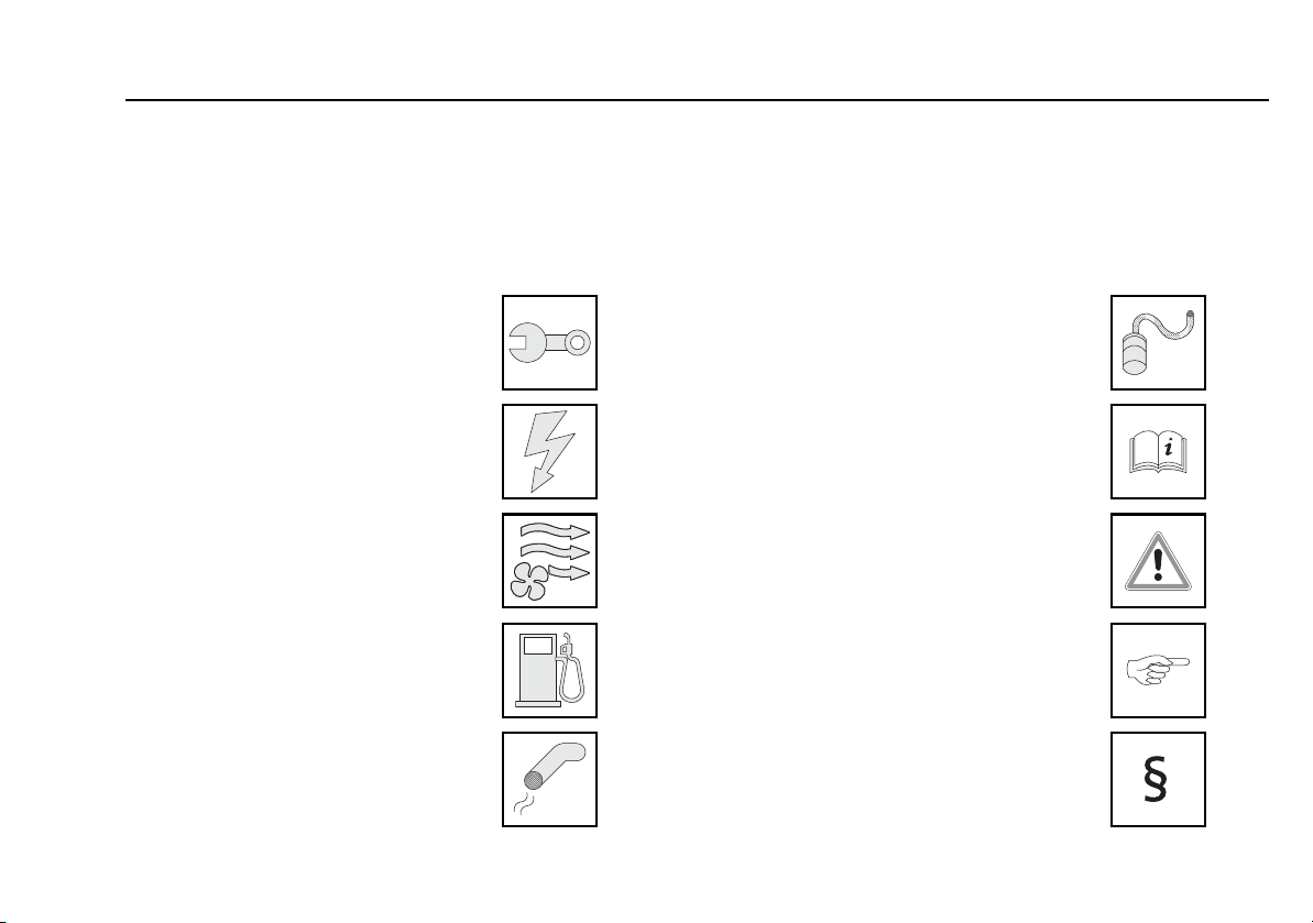
To enable quick reference to the individual procedures you will find a descriptive symbol on the top outer edge of each page.
Boat Air Heaters
Mechanical system
Electrical system
Heated air
Fuel
Exhaust
Combustion air
Technical Information
Attention
Note
Excerpt from directive
49
Page 5
Technical Information Boat Air Heaters
2 Regulations governing installation
2.1. Statutory regulations governing installation
Permit numbers see Chapter 13, "Technical data".
2.2. Application of combustion heaters on boats
Observe regional authority regulations! Establish which regulations
apply in the area where the boat is to be used. Comply with the
stipulated requirements!
Obtain official approval if necessary!
The cables must be installed and firmly secured such that the wirings
are adequately protected against mechanical and thermal stress.
Requirements relating to the basic unit:
When switched off, it is permissible for combustion heaters to continue
running for max. 40 seconds. Only combustion heaters are to be used
with heat exchangers that are not damaged during their standard
operating period by the reduced afterrunning time of 40 seconds.
2.3. Additional documentation to be used
These installation instructions contain all the information
and instructions necessary to install Air Top 2000 ST / Evo
40 / Evo 55 heaters.
The operating instructions must also be observed.
Air Top 2000 ST / Evo 40 / Evo 55
50
Page 6

Boat Air Heaters Technical Information
Air Top 2000 ST / Evo 40 / Evo 55
3 Use / variants
3.1. Use
The Webasto Air Top 2000 ST, Air Top Evo 40 and Air Top Evo 55 air
heaters are suitable for:
Preheating and heating ship's cabins, cargo holds, passenger and crew
areas
Use on inland waterways and at sea
Sailing and motor boats of approx. 8 to 24 m in length
Not suitable for:
Continuous heating of living areas, houseboats, etc.
Heating and/or drying living creatures
The heaters operate independently of the boat's engine. They are
connected to the boat's fuel tank and electrical system.
3.2. Variants
Air heater for "diesel" fuel (12 or 24 V):
Air Top 2000 ST D (Diesel)
Air Top Evo 40 D (Diesel)
Air Top Evo 55 D (Diesel)
51
Page 7
Technical Information Boat Air Heaters
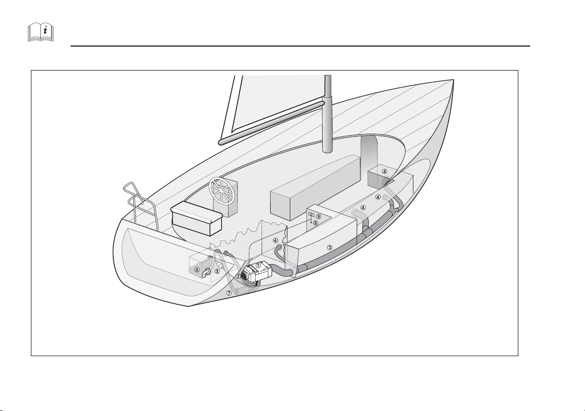
1. Air heater
2. Cold air intake;
3. Hot air hoses;
4. Air outlet;
5. Fuel pump;
6. Fuel tank;
7. Exhaust line;
8. Room temperature sensor;
9. Control element
4Heater
Air Top 2000 ST / Evo 40 / Evo 55
Fig. 1 Installation example
52
Page 8
Boat Air Heaters Technical Information
Air Top 2000 ST / Evo 40 / Evo 55
4.1. Choosing installation location
ATTENTION:
Danger of suffocation!
Do not install heater and exhaust system in accommodation
areas.
Install the heater in a dry location, protected from the ingress of sea
water, excessive vibration, heat, engine exhaust gases and soiling by
fuel or oil (requirement from 2001/56/EC).
Arrange the installation to suit the requirements and type of boat! Take
the following into account: all peripheral components, such as permissible length of the exhaust system, position of the through-hull fitting,
combustion air intake, routing of electrical wiring and cable lengths,
distance from the fuel tank, routing of hot air hoses, fresh air intake,
etc.
Take the following into account: the maximum inclination of the boat
must not result in the ingress of sea water through the exhaust gas
outlet.
The inclination must not cause the heater to come in cont ac t w it h bilge
water.
No obstruction of moving parts (e.g. rudder assembly).
Every reasonable precaution should be taken when positioning the
heater to minimise the risk of injury and damage to personal property
(requirement from 2001/56/EC)
ATTENTION:
Danger of fire!
Do not install in the vicinity of flammable or temperature-
sensitive objects such as sails, fenders, bulkheads, paper,
gas lines, fuel containers, etc.
When installing in locker or rudder box:
– Only with good ventilation
– Prevent contact with hot parts
– Install a contact barrier around the heating system if
necessary
53
Page 9
Technical Information Boat Air Heaters
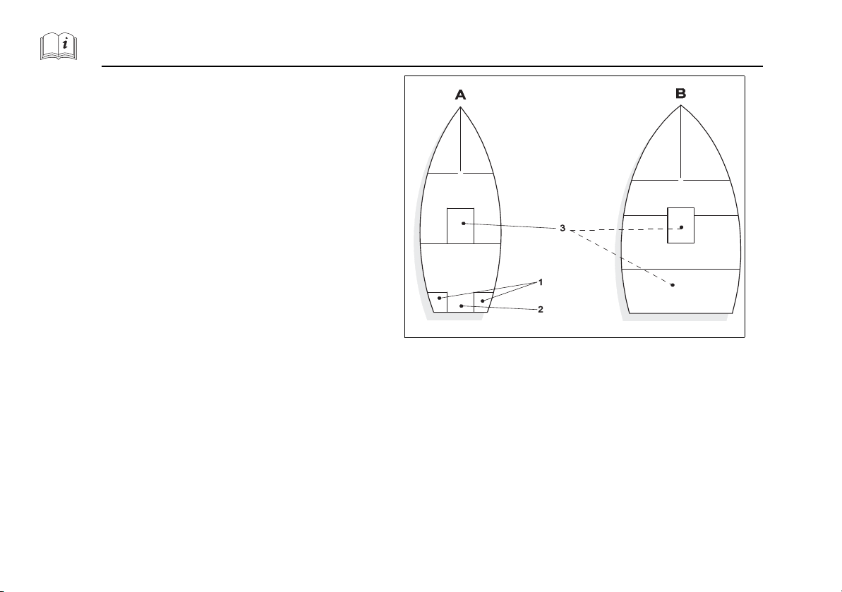
Recommended installation locations (see Fig. 2):
A) In locker or rudder box if it is well ventilated.
Install a contact barrier around the heating system so that sails,
fenders, bulkheads, etc. do not come in contact with hot parts!
B) In the engine compartment of inboard diesel engines. Condition:
cold air intake from outside, combustion air intake from outside or
from engine compartment if this is well ventilated to the outside!
Air Top 2000 ST / Evo 40 / Evo 55
54
Fig. 2 Installing heater in locker (1), rudder box (2) or engine
compartment (3)
Page 10
Boat Air Heaters Technical Information
1
6 5 4
2 3
B AC
2
Air Top 2000 ST / Evo 40 / Evo 55
4.2. Heater data
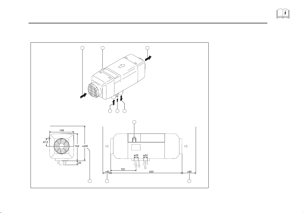
4.2.1. Dimensions Air Top Evo 40 / Air Top Evo 55
1)
Cold air inlet
2) Cable outlet (optionally on right or left)
3) Hot air outlet
4) Exhaust gas outlet
5) Fuel inlet
6) Combustion air inlet
A) Space requirements for hot air outlet
B) Space requirements for cold air inlet
C) Space requirements for removing heater
Fig. 3 Dimensions and space requirements [mm] Air Top Evo 40 / Air Top Evo 55
55
Page 11
Technical Information Boat Air Heaters
1
6 5 4
2 3
B
A
C
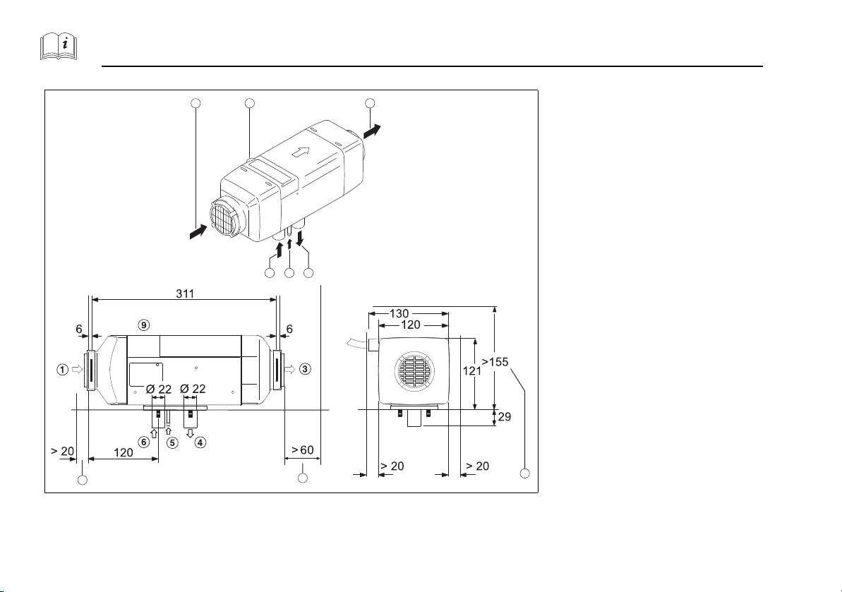
4.2.2. Dimensions Air Top 2000 ST
Air Top 2000 ST / Evo 40 / Evo 55
1) Cold air inlet
2) Cable outlet (optionally on right or left)
3) Hot air outlet
4) Exhaust gas outlet
5) Fuel inlet
6) Combustion air inlet
A) Space requirements for hot air outlet
B) Space requirements for cold air inlet
C) Space requirements for removing heater
Fig. 4 Dimensions and space requirements [mm] Air Top 2000 ST
56
Page 12
Boat Air Heaters Technical Information
Air Top 2000 ST / Evo 40 / Evo 55
ATTENTION:
Danger of drowning!
There is a danger of drowning when drilling into the boat's
outer skin! Drilling below the water line can cause the boat
to sink!
If the boat is in the water: check the drilling location! Have
leak sealing equipment available beforehand and familiarise
yourself with possible escape routes!
ATTENTION:
A blockage in the heating air rotor can cause the
heater to overheat!
Damage to heater
Make sure that the casing of the heater is clear, i.e. does
not make contact with any other parts, in installed position (see Fig. 7).
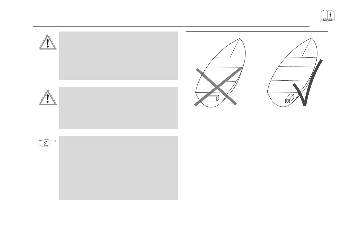
NOTE:
Installation positions: observe possible inclination of
boat!
Recommended installation position: exhaust gas outlet
routed downward, heater parallel to longitudinal axis of
boat.
Do not install transversely in sailing boats!
Exception: if heater is primarily operated when boat is
moored or in motor boats then installation transverse to
longitudinal axis is permissible.
Fig. 5 Install heater in longitudinal direction in sailing boats!
4.3. Heater mounting
• Securely mount the heater (vibration, swell)! Use the supplied bracket
and rubber seal under the base.
• This rubber seal must be replaced each time the heater is reinstalled.
• The M6 nuts must be tightened to 6 Nm (-0 Nm, +1 Nm) to mount
the base.
57
Page 13

Technical Information Boat Air Heaters
Fig. 6 Mounting Air Top with bracket
NOTE:
After installation check that the casing is not in contact with
any part of the boat's body. Failure to do this may result in
the heating air fan blocking.
Fig. 7 Ensure ease of movement of all moving parts!
Air Top 2000 ST / Evo 40 / Evo 55
.
ATTENTION:
There is a danger of drowning when drilling into the
boat's outer skin!
Drilling below the water line can cause the boat to sink!
If the boat is in the water: check the drilling location!
Have leak sealing equipment available beforehand and
familiarise yourself with possible escape routes!
• Determine space requirements and installation position
– Air Top 2000 ST:
see Fig. 3 and Fig. 7
– Air Top Evo 40 / Air Top Evo 55:
see Fig. 4 and Fig. 8
• Do not exceed inclination angle (see Fig. 8).
• Recommendation: flexible mounting (vibration decoupling, noise reduction)!
• Secure the heater onto the bracket with bolts.
• Recommendation when mounting on outer skin on FRP boats: laminate wooden panel onto the fastening location from the inside to
prevent drilling through the outer skin.
58
Fig. 8 Permissible installation positions of diesel-operated air
heaters
ATTENTION:
The base seal must be replaced when removing and
reinstalling a heater.
Page 14

Boat Air Heaters Technical Information
Air Top 2000 ST / Evo 40 / Evo 55
• Except for the year of installation, remove all the year numerals on
the type label.
• Secure heater. Tighten the M6 nuts to 6 Nm (–0 Nm, +1 Nm).
NOTE:
After installing the heater, the type label should be clearly
visible in a well-protected position.
• If the type label is not visible after installing the heater: use the type
label duplicate.
59
Page 15
Cold and hot air Boat Air Heaters
Air intake from well-ventilated locker Air intake with intake hose directly
from outside
5 Cold and hot air
Air Top 2000 ST / Evo 40 / Evo 55
5.1. General
ATTENTION:
Danger of suffocation!
The cold air intake must be from a clean area with no exhaust gases.
Cold air intake never from the engine compartment!
It must not be possible for stowed articles to block the intake opening
(requirement from 2001/56/EC).
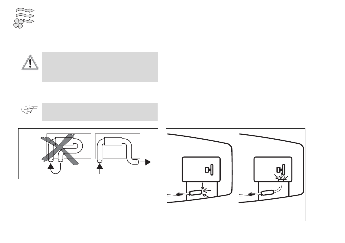
NOTE:
The direct intake of hot air must be avoided (see Fig. 9).
It is not permitted to short-circuit the air flow.
Fig. 9 Cold air inlet and hot air outlet
5.2. Fresh air mode
Cold air is drawn in from the outside, heated and blown into the boat's
interior. This renews the cabin air and reduces humidity. Ensure there are
enough ventilation openings in the cabins! A room temperature sensor
must be installed for temperature control, preferably in the saloon. In
summer, ventilation is also possible (when comfort control element is
used).
Draw in cold air directly from lockers or rudder boxes if they are dry,
clean and free of odours and exhaust gases.
For proper ventilation, ensure the intake diameter = 1.5 x hose diameter of the heater.
Otherwise, use an intake hose for intake from the outside.
Prevent water from entering through the intake opening.
60
Fig. 10 Air intake
Page 16
Boat Air Heaters Cold and hot air
Air Top 2000 ST / Evo 40 / Evo 55
NOTE:
For fresh air mode, a room temperature sensor must be
installed in the cabins to be heated.
5.3. Recirculated air mode
In recirculated air mode, the air to be heated is taken from the interior
area. The advantage of this is that heating takes place faster due to more
effective heat utilisation. However, the humidity is not reduced or the
room air not renewed in this mode.
No room temperature sensor needs to be installed. The heater uses the
sensor integrated in the control unit.
5.4. Position of hot air openings
WARNING:
Risk of injury!
Do not blow hot air directly onto living creatures or
temperature-sensitive objects.
All areas in the boat can be evenly heated with an appropriate air
distribution system. For this purpose, branch off several side branches
from the main line to reach all cabins. The air, and therefore the heat
flow, can be influenced by suitable selection of the branches and hose
diameters.
See the accessories catalogue for branches, connecting elements, Yjunctions, air outlets, etc. made from temperature-resistant material.
A free flow of air into the cabins provides the most effective cabin
heating and air circulation!
Only use one or two air outlets per cabin!
5.5. Properties of cold and hot air ducts
Recommended inside diameter of main hot air duct:
• 80 mm for Air Top 2000 ST
• 80 mm for Air Top Evo 40
• 90 mm for Air Top Evo 55
NOTE:
Only materials with a thermal resistance of 130 °C (shortterm 150 °C) are to be used for the hot air duct.
5.6. Layout of cold and hot air ducts
ATTENTION:
Use without cold air intake hose
Risk of injury by rotating heating air rotor
If used without the cold air intake hose, install the sup-
plied mesh guard over the intake
Maximum differential pressure between intake and pressure side of
heater:
• Air Top 2000 ST: 2.0 hPa
• Air Top Evo 40: 2.0 hPa
• Air Top Evo 55: 3.0 hPa
ATTENTION:
The heating output will be reduced if this pressure differential is exceeded.
61
Page 17

Cold and hot air Boat Air Heaters
5.7. Installing cold and hot air ducts
Do not route the ducts through the bilge.
Hot air ducts in damp areas: use temperature-resistant, flexible, metal
spiral-reinforced plastic hoses.
Secure cold and hot air ducts at all connections.
In stowage areas:
Use a perforated metal cover, for example, to protect the ducts from
damage by cargo.
Recommended:
Routing through bulkheads:
Use wall lead-through as shown in Fig. 11.
See the Webasto accessories catalogue.
Secure ducts:
– With hose clips at all connecting elements.
– Prevent from chafing, see Fig. 12.
Recommendation
for routing hoses through area not to be heated: insulate the hose sections to prevent heat loss.
Air Top 2000 ST / Evo 40 / Evo 55
Fig. 11 Recommended duct lead-through in bulkheads
Fig. 12 Recommended routing around corners
62
Page 18

Boat Air Heaters Cold and hot air
A: in 9 m sailing boat
B: in 11 m sailing boat
C: in 13 m sailing boat
1) Cold air intake
2) Y-junction or T-piece
3) Air outlet
Air Top 2000 ST / Evo 40 / Evo 55
5.8. Silencer in air duct
Recommendation: For Air Top 2000 ST / Evo 40 / Evo 55 units with short
air duct, use silencer on intake and/or outlet side (reduction in noise
level). See the accessories catalogue.
Fig. 13 Silencer for reducing noise level
5.9. Air routing examples
2000ST
EVO 40
EVO 55
Fig. 14 Heating air routing examples
The main duct must not be reduced from 90 to 80 mm for Air Top Evo 55!
If 90 mm is not possible throughout, it is better to use Y-junction 90/80/
80 and thus create two 80 mm main ducts.
63
Page 19

Cold and hot air Boat Air Heaters
37' sailing boat
1 Branch 90/60/90
2 Air outlet Ø 60 mm, can
be closed off
3 Y-junction 90/90/90
4 Air outlet Ø 90 mm, open
5 Y-junction 60/60/60
6 Air outlet Ø 90 mm, can
be closed off
7 T-piece 90/60/90
43' sailing boat
5.10. Installation examples:
Air Top 2000 ST / Evo 40 / Evo 55
Fig. 15 Installation examples:
64
Page 20

Boat Air Heaters Fuel
1) Fuel pump
2) Fuel extractor
3) Tank extracting device
4) Fuel tank
5) Fuel line
6) Heater
Air Top 2000 ST / Evo 40 / Evo 55
6Fuel supply
6.1. General
ATTENTION:
Danger of fire!
If the heater takes the fuel from a separate additional tank,
the fuel type and the filler neck must be clearly marked.
(Requirement from 2001/56/EC).
The fuel filler neck must not be located in the interior of the boat and
must be fitted with a well-sealing cap to prevent fuel from escaping
(requirement from 2001/56/EC).
Protect the boat hull/components in the vicinity of the heater from
heat/contamination by fuel/oil!
NOTE:
– Fuel take-off must take place with virtually no pressure.
– If taking fuel from the return line make sure that the line
is not blocked by non-return valves.
Fig. 16 Example of fuel supply Air Top heaters
6.2. Fuel extraction
The following alternatives are available for extracting fuel for the heater:
6.2.1. Tank extracting device
• Fuel take-off directly from the boat's fuel tank.
• Plastic fuel tanks: install the tank extracting device in the tank fitting.
Do not drill into a plastic fuel tank.
• For suitable tank extracting device for metal tanks see the accessories
catalogue or scope of delivery.
65
Page 21

Fuel Boat Air Heaters
Air Top 2000 ST / Evo 40 / Evo 55
6.3. Fuel extractor
Fig. 17 Installing a tank extracting device in metal tank
Install the tank extracting device as shown in Fig. 17:
1) Shorten the immersion tube: the end should be approx. 25 mm
above the bottom of the tank or high enough that fuel for the boat
engine always remains in the tank. Cut the tube diagonally.
Deburr the cut edges.
2) Drill a hole in the tank or tank fitting from above.
Use suitable drilling attachment.
Grease the drill bit and drilling surface beforehand (to catch small
drilling chips).
3) Fit the tank fitting into the hole and screw tight (the seal is slightly
compressed).
6.2.2. Fuel take-off coupling
If there is an unused fuel take-off coupling already fitted in the boat's fuel
tank then use it.
Do not take fuel from the drain plug at the bottom of the tank as dirt or
water can be drawn in from the drain.
66
Fig. 18 Fuel extractor
The fuel extractor is a special T-piece with an integrated bubble separator.
It can be installed in the supply line to the engine if no pre-supply pump
is installed in the fuel tank or in the return line from the engine if it almost
reaches the bottom of the fuel tank. Take into account the diameters of
the installed pipes when selecting the fuel extractor.
See the Webasto accessories catalogue for a suitable fuel extractor.
6.4. Pipe lengths and delivery head
When installing the fuel line make sure that it is kept as short as possible.
See Fig. 19.
The pipe must be installed such as to protect it from being damaged.
The fuel line must be installed in cool areas to avoid bubbles being
formed by the effect of heat. High fuel temperatures can cause the heater
to malfunction.
Page 22

Boat Air Heaters Fuel
H
1
D
1
l
1
l
2
l
2
H
2
l
1
D
2
S
2
D
2
D
1
S
1
Air Top 2000 ST / Evo 40 / Evo 55
The fuel lines must be secured using state-of-the-art fastening elements.
Do not damage the fuel line.
Intake side:
D1: Inside diameter of fuel line = 2 mm.
: Fuel level (tank above fuel pump) [m]
H
1
: Fuel level (tank below fuel pump) [m]
S
1
l
: Length of fuel line [m]
1
Pressure side:
D2: Inside diameter of fuel line = 2 mm.
H
: Height difference between heater and fuel pump
2
(heater above fuel pump) [m]
S
: Height difference between heater and fuel pump
2
(heater below fuel pump) [m]
l
: Length of fuel line [m]
2
Fig. 19 Fuel supply
Fuel level (tank above fuel
[m]
pump), H
1
Maximum permissible fuel pressure at take-off
[bar]
point, p
1
H1 = 0 -0.1 < p1 <+0.5
0 < H1 <1 -0.1 < p1 <+0.4
1 < H1 <2 -0.1 < p1 <+0.3
Fuel level (tank below fuel
[m]
pump), H
2
<1.3 -0.1 < p1 <+0.5
0 <H
2
Maximum permissible fuel pressure at take-off
[bar]
point, p
1
67
Page 23

Fuel Boat Air Heaters
1) Fuel pipe connection
Parameter Value
Length of intake pipe l
Length of pressure pipe l
Length of intake pipe l
Height difference between heater and fuel pump
(heater above fuel pump) H
Height difference between heater and fuel pump
(heater below fuel pump) S
6.4.1. Pipe material
Only use steel or plastic fuel lines made from light and temperatureresistant PA11 or PA12 (e.g. Mecanyl-RWTL) in accordance with DIN
73378 as the fuel pipes.
6.4.2. Connecting 2 fuel lines to a hose
Fig. 20 shows the correct connection of fuel lines to a hose.
Make sure there are no leaks!
Fig. 20 Pipe/hose connection
[m] max. 5
1
[m] max. 10
2
+ length of pressure pipe l2 [m] max. 12
1
[m]
2
[m]
2
max. 3
max. 1
Air Top 2000 ST / Evo 40 / Evo 55
Fuel line material (metal/plastic): observe regional/national
regulations!
ATTENTION:
Danger of fire!
• The fuel lines in the engine compartment must be made
of metal and the connecting hoses between the individual components of fire-resistant material (as per DIN EN
ISO 7840)!
• If the fuel pump is equipped with a plastic fuel damper
(e.g. Air Top 2000 ST Diesel) it must be protected with a
protective sleeve (see accessories catalogue) when installed in the engine compartment.
• Only use fire-resistant fuel filters in accordance with ISO
7840 for installation in the engine compartment.
For installation kits for metal fuel lines see the accessories catalogue.
68
Fig. 21 Stainless steel hose clips
Page 24

Boat Air Heaters Fuel
Air Top 2000 ST / Evo 40 / Evo 55
NOTE:
– Only use stainless steel hose clips to secure plastic lines.
– Metal pipes: ensure cleanliness and neatness while
carrying out the work! Remove all soiling and burrs from
the connection points prior to assembly!
– Do not overtighten union nuts (otherwise leaks may
occur).
– Route the fuel lines as straight as possible and at a slight
incline so that air bubbles escape towards the heater.
– Secure the line at regular intervals to prevent sagging,
avoid kinks.
– Keep away from heat sources. Use heat shield if
necessary!
– Inside ø of fuel line = 2 mm, larger diameters will cause
problems due to gas bubbles.
6.5. Fuel pump
Air Top 2000 ST heaters must only be operated with the fuel pump DP 30.
Air Top Evo 40 / Air Top Evo 55 heaters must only be operated with the
fuel pump DP 42.
The fuel pump is a combined delivery, metering and shut-off system and
is subject to certain installation criteria (see Fig. 22 (DP 30) or Fig. 23 (DP
42) for installation positions).
The fuel pump is controlled with a separate wiring harness and feeds the
fuel into the combustion chamber of the heater depending on the
required heating capacity. Due to the individual delivery strokes, the
separate fuel pumps make a ticking noise during operation.
6.5.1. Installation location
The fuel pump must not be installed within the radiated head range of
hot components. Fit a heat shield if necessary. The fuel pump should be
preferably installed close to the fuel tank.
Install the pump in a dry/cool area. Do not install in the bilge.
Check the direction of flow of the pump.
For permissible ambient temperature see Chapter 13, "Technical data".
6.5.2. Installation and attachment
The installation position is restricted (maximum inclination angle and
axial installation position of fuel pump) as illustrated in Fig. 22 (DP 30) or
Fig. 23 (DP 42).
The arrow shows the direction of flow.
69
Page 25

Fuel Boat Air Heaters
Air Top 2000 ST / Evo 40 / Evo 55
Use the flexible mount to install the fuel pump
(reduces the transmission of structure-borne noise/ticking)!
(see Fig. 24).
Fig. 24 Flexible mount of fuel pump
Fig. 22 DP30 Fuel pump installation position
Fig. 23 DP42 Fuel pump installation position
70
NOTE:
Recommended installation: mount on solid and sturdy part
of boat.
Page 26

Boat Air Heaters Fuel
0° - 90°
Air Top 2000 ST / Evo 40 / Evo 55
6.6. Fuel filter
Fig. 26 Fuel filter, installation position and direction of flow
Fig. 25 Fuel line mounting
• Recommended fuel line mounting: Distance from fuel pump ≥ 20 cm
or with a bend to avoid structure-borne noise being transmitted
through the pipe.
• Fuel line secured to wall and not too close to the fuel pump.
Install a suitable fuel filter (e.g. Webasto fuel filter) if dirty fuel is to be
expected. Wherever possible install vertically, deviating by no more than
90° (see Fig. 26).
NOTE:
Pay attention to installation position and direction of flow.
71
Page 27

Fuel Boat Air Heaters
6.7. Auxiliary tank
ATTENTION:
If an auxiliary tank is required for the fuel supply to the
heater:
It must only be installed by a specialist company for marine
applications (with the necessary knowledge of the required
standards, regulations and directives)!
6.8. Special requirements for heaters in boats with petrol engine
ATTENTION:
Petrol-operated heaters are not permitted in recreational
boats covered by ISO 9094. Local regulations and special
safety requirements must be complied with.
Specific requirements apply to the installation of diesel-operated
heaters in petrol engine boats:
• The heater must be supplied with fuel from a separate diesel tank
which must comply with the valid regulations for diesel tanks in boats.
• Do not install heaters wherever flammable petrol vapours can form,
i.e. especially in engine compartments, fuel tank compartments and
rooms directly annexed to them.
• The combustion air intake must come from the outside and not from
the engine compartment!
• Do not route exhaust pipes through engine or tank compartments.
Air Top 2000 ST / Evo 40 / Evo 55
72
Page 28

Boat Air Heaters Combustion air
Air Top 2000 ST / Evo 40 / Evo 55
7 Combustion air supply
7.1. Combustion air intake line
Combustion air intake line: must be arranged that it cannot be blocked
by objects
Keep combustion air intake line as short as possible
Mounting of combustion air intake line: with a hose clip at the intake
connection piece of the heater and with pipe clamps or cable ties on
fixed built-in components.
7.2. Combustion air intake from a well-ventilated area (locker, stowage compartment or engine compartment)
No through-hull fitting required
The intake area must be at ambient pressure and sufficiently ventilated
to the outside!
Intake from engine compartment: the ventilation fan in the engine
compartment must not produce an overpressure or negative pressure
in the engine compartment.
Intake point: no intake of exhaust gases from heater or engine!
Fit a cap over the end of the hose to prevent water ingress (if no
through-hull fitting is used).
7.3. Combustion air intake directly from outside
Use a separate through-hull fitting if intake from a ventilated area is
not possible.
Arrange the end of the combustion air intake line as a gooseneck, as
illustrated. Prevent water from entering through the intake opening.
Do not position the through-hull fitting in the direction of travel (other-
wise backpressure and water ingress may occur in the intake pipe).
Fig. 27 Combustion air intake line not in direction of travel
Drill a drain hole at the lowest point as illustrated in Fig. 27.
Route hose free of kinks.
NOTE:
A combustion air intake line is required.
A minimum length is not specified.
73
Page 29

Combustion air Boat Air Heaters
Air Top 2000 ST / Evo 40 / Evo 55
NOTE:
The combustion air intake line with silencer must not exceed
a max. length of 2.0 m.
7.4. Properties of combustion air intake line
CAUTION:
The exhaust pipe can be confused with the combustion air intake line!
Damage to fuel pump cable
Fit the exhaust pipe only to the exhaust outlet socket cou-
pling
Do not use a metal combustion air intake line
Combustion air intake line Value
Inside diameter 25 mm
Smallest bending radius 50 mm
Max. sum of all bends 270°
7.5. Combustion air intake silencer
NOTE:
A combustion air intake silencer must be installed if the
length of the combustion air intake line is less than 0.5 m.
74
Page 30

Boat Air Heaters Exhaust
1) Heater
2) Combustion air intake line
3) Flexible stainless steel exhaust pipe
4) Condensed-water drain
5) Exhaust silencer
6) Insulation
7) Gooseneck
8) Through-hull fitting
Air Top 2000 ST / Evo 40 / Evo 55
8 Exhaust system
8.1. General 8.2. Exhaust gas outlet
ATTENTION:
Generation of heat by incorrect positioning of exhaust pipe outlet!
Injuries or damage to property caused by fire
Pay attention to installation position.
Outlet arrangement:
Position the exhaust gas outlet where no splash water can enter the
boat.
Recommendation:
Sailing boats: in stern transom.
Motor boats: in side wall.
ATTENTION:
Danger of suffocation!
Do not position the exhaust gas outlet below or next to
ventilation equipment, window openings or the heating
air inlet
At least 60 cm above the water line so that no water can enter when
the boat is heeling
Not in direction of travel of the boat (high wind pressure)
Do not connect to engine or generator exhaust system (higher pres-
sures; damage to heater!)
Fig. 28 Exhaust system
Not where it can be easily covered, e.g. by fender.
75
Page 31

Exhaust Boat Air Heaters
1) Gasket
2) Counterflange
3) Bolt/washer/nut
4) Side wall
5) Webasto mark
Through-hull fitting:
Choice of design and installation position to minimise rain water in-
gress!
Only use genuine Webasto through-hull fittings! Fit insulation plate ex-
actly for thermal isolation from the side wall (minimisation of water ingress)!
If additional sealing is required: use only heat-resistant sealing compound!
Through-hull fitting: cannot be closed; not with self-opening flaps!
Mount through-hull fitting with pipe socket angled upward.
Air Top 2000 ST / Evo 40 / Evo 55
Fig. 29 Through-hull fitting
NOTE:
Avoid drawing in exhaust gas with the combustion air.
76
Page 32

Boat Air Heaters Exhaust
Air Top 2000 ST / Evo 40 / Evo 55
8.3. Notes on exhaust pipe
The exhaust pipe must be secured to the heater with a clamp suitable for
the exhaust pipe.
Use suitable insulation material to avoid the dew point dropping below
the minimum value.
Keep exhaust pipe as short as possible.
No contact with temperature-sensitive objects such as electrical wir-
ing, water lines, plastic parts, sails or boat hull!
8.4. Length of exhaust pipe and combustion air intake line
For the Air Top 2000 ST / Evo 40 / Evo 55, the following maximum total
lengths of the combustion air intake line and exhaust pipe must be complied with:
– With exhaust silencer: max. 2.5 m
– Without exhaust silencer: max. 5.0 m.
Properties of exhaust pipe
ATTENTION:
The exhaust pipe can be confused with the combustion air intake line!
Damage to fuel pump cable
Fit the exhaust pipe only to the exhaust outlet socket cou-
pling
Exhaust line Value
Internal diameter 24 mm
Smallest bending radius 50 mm
Max. sum of all bends 270°
Minimum length 0.5 m
Exhaust silencer
Use the genuine Webasto exhaust silencer provided! It considerably reduces noise. There are no restrictions in terms of installation position and
direction of flow.
Do not drill a condensation drain hole in the silencer (this will cause exhaust to escape)!
To prevent impermissible vibration, the exhaust silencer itself must be secured with a clip to fixed parts of the boat at 50 cm intervals.
The heater can also be operated without a silencer.
For suitable models see the Webasto accessories catalogue.
Fig. 30 Approved hose clamps for mounting exhaust pipes
77
Page 33

Exhaust Boat Air Heaters
Air Top 2000 ST / Evo 40 / Evo 55
Condensed-water drain
Fit a condensed-water drain (non-rusting) if the exhaust pipe is longer
than 2 m!
A) With a T-piece at the lowest point in the exhaust pipe or
B) If the heater itself is at the lowest point: use an exhaust connection
piece with an integrated condensed-water drain.
For suitable components see the Webasto accessories catalogue.
Use a container or drain hose to collect the condensation water.
Different versions of the condensed-water drain fitting are available.
Fig. 31 Condensed-water drain fitting
8.5. Thermal insulation
Observe the following points when installing the exhaust pipe:
Avoid contact between the hot exhaust pipe and temperature-sensi-
tive objects such as electrical wiring, water lines, plastic parts, sails or
boat hull!
If contact with persons/objects is possible during heating: Insulate the
exhaust pipe or fit contact barrier! For suitable exhaust insulation materials see the Webasto accessories catalogue.
Fig. 32 Exhaust pipe insulation sheathing
Surface temperature ≤ 80 °C!
Minimum distance from walls ≥ 20 mm.
8.6. Gooseneck
Last section of exhaust pipe: gooseneck sloping downward to the outlet
(due to possible ingress of water)!
Height of gooseneck: ≥ 20 cm.
78
Page 34

Boat Air Heaters Electrical system
Air Top 2000 ST / Evo 40 / Evo 55
9 Electrical Connections
The free ends of all lines that are not required must be insulated!
9.1. Electrical system, general
• Observe all information and safety precautions!
• Install a clearly visible operation indicator to show whether the heat-
ing is switched on or off (requirement from 2001/56/EC). This is already integrated in the Webasto control elements.
• Install all wiring harnesses and electrical components in dry and pro-
tected areas!
• The free ends of all lines that are not required must be insulated.
• If there is highly sensitive electronic equipment on board, special
electrical interference suppression measures may be necessary. Contact an authorised Webasto partner.
• Do not touch exposed PCBs of the unit (electrostatic discharge).
• For connector designations see the legend and wiring diagrams,
Page 87.
9.2. Wiring harnesses
Fig. 33 and Fig. 34 show the wiring harnesses for Air Top 2000 ST and
Air Top Evo 40 / Air Top Evo 55
Fig. 33 Wiring harness Air Top 2000 ST
79
Page 35

Electrical system Boat Air Heaters
40/55
Fig. 34 Wiring harness Air Top Evo 40 / Air Top Evo 55
NOTE:
Use a blunt blade on both sides to remove the control unit
cover (Fig. 35 arrows).
Air Top 2000 ST / Evo 40 / Evo 55
Fig. 35 Removing control unit cover
9.3. Connecting heater
To connect the heater, remove the control unit cover on the heater and
plug in the wiring harness connector at the control unit. Connect voltage
supply.
To prevent the hot air escaping (heater overheating), reattach the control
unit cover prior to initial operation.
The cable lead-through can be either on the left or right.
Correspondingly position the cable grommet on the wiring harness to
ensure that the cable lead-through is sealed off in the control unit cover.
ATTENTION:
To enable afterrunning, the heater must not be shut down
(disconnected from the power supply).
An electrical battery disconnector can be installed in the
electrical circuit (see wiring diagram Fig. 52).
80
Page 36

Boat Air Heaters Electrical system
“a”
X7
Air Top Evo 40 /
Air Top Evo 55
X6
Air Top 2000 ST
X5 sw/bl
ge
X5
Air Top 2000 ST / Evo 40 / Evo 55
Air Top 2000 ST:
The connector for the Air Top 2000 ST must be plugged in as far as point
"a".
See Fig. 36.
Fig. 36 Connector to heater control unit
Air Top Evo 40 / Air Top Evo 55:
Remove and dispose of the protective cap on the control unit. Plug
connector X5 of the wiring harness for the room temperature sensor into
this socket.
See Fig. 37.
Fig. 37 Plugging in room temperature sensor at control unit
Correspondingly position the cable grommet on the wiring harness to ensure that the cable lead-through is sealed off in the control unit cover.
Route the wiring harness out of the heater and fit the cover (possible in
both directions).
The heater must not be operated without the control unit cover (this will
cause the heater to overheat).
9.4. Power supply
• Power supply to heater: from the boat's service battery (not the starter battery for the engine due to risk of discharge).
Connect the red cable to the "+" terminal of the battery.
This connection should always be made before the main switch to
enable heater afterrunning.
Connect the brown cable to earth directly at the battery.
• The wiring harness for the Air Top Evo 40 / Air Top Evo 55 includes
cable K (Fig. 34, colour red/black) for optional control of a battery
disconnector or an additional operation indicator. If not required for
this purpose, insulate the end of the cable.
• Keep power supply cables as short as possible. Shorten the cables if
necessary.
• Cross section of connection cables: 4.0 mm².
If cable lengths > 7.5 m: 6.0 mm²
• When extending cables, make sure the total cross section is adequate and the insulation matches.
• The heater must be protected with a fuse (F1).
F = 20 A (12 V)
F = 15 A (24 V)
• If the MC04 control element is used with the Air Top Evo 40 / Air Top
Evo 55 a 1A fuse (F3) must be inserted in the fuse holder.
• The fuse must be installed splash water-protected in the interior.
• Distance of the main fuse from the "+" battery terminal: 1m
81
Page 37

Electrical system Boat Air Heaters
Fig. 38 Fuse holder on wiring harness
9.5. Temperature control
Install a room temperature sensor in the boat's interior (mandatory for
fresh air operation)!
The heater continually compares the set temperature (value set at the
control element) and the actual temperature (measured at the room temperature sensor) and automatically adjusts the heating capacity.
ATTENTION:
The Air Top heater is a separate system that operates
independently of the engine with integrated temperature
control.
An additional automatic control system for the purpose of
controlling the temperature is not permitted.
Air Top 2000 ST / Evo 40 / Evo 55
9.5.1. Installing room temperature sensor
Mount the sensor in a favourable/suitable position in the room to be
heated.
The distance to the control element is 2.5 m due to the cable length.
Use a room temperature sensor with a 5 m long cable for greater distances, see the Webasto accessories catalogue.
The position has a decisive effect on the control characteristics!
NOTE:
– In largest cabin to be heated
– In position at average room temperature
– At half the room height if possible
– On a vertical interior wall if possible, not directly on an
outside wall
Not in the air flow of hot air outlets
Not within the range of the companionway
Not in the vicinity of heat sources
Not behind cushions or curtains
Not in direct sunlight
82
Page 38

Boat Air Heaters Electrical system
ge
sw/bl
X12
X11
sw
rt
Air Top 2000 ST / Evo 40 / Evo 55
9.5.2. Connecting room temperature sensor
Route the cable of the room temperature sensor up to the installation location of the control element. Here connect the sensor cable to the main
wiring harness, see Fig. 40.
Plug cable of room temperature sensor with the white connector housing
X11 into the socket on the main wiring harness.
9.6. Control element
This control switches the heater ON/OFF and defines the setpoint for the
interior temperature.
Position: mount in the interior such that it is easily accessible, visible and
protected from water. The position has no effect on the control characteristics!
Fig. 39 Room temperature sensor for registering interior
temperature
Fig. 40 Wiring of room temperature sensor
Various control elements with different functions are available, see the
accessories catalogue.
NOTE:
Only pull on the connector housing to unplug the
connector.
The connector housing will lock (self-locking action) by pulling on the wiring harness.
83
Page 39

Electrical system Boat Air Heaters
ge, sw/bl
gn/ws,
X9a
X9b
Air Top 2000 ST
Air Top Evo 40 / Air Top Evo 55
9.6.1. Rotary switch
Connect the control element (ON/OFF and temperature preselection)
with rotary potentiometer directly to the wiring harness.
See Fig. 42.
Air Top 2000 ST:
Connector X9: preinstalled connector for control element.
Use the red/white (rt/ws) cable for the ventilation switch (option). When
using a ventilation switch install an earthing cable leading to the switch.
See Fig. 41
Air Top Evo 40 / Air Top Evo 55:
Plug connector X9a (red, blue, white, black wires) with blue marking into
the connector at the control element.
Connector X9b with the red marking is not required.
See Fig. 41
Air Top 2000 ST / Evo 40 / Evo 55
Fig. 42 Control element
Fig. 43 Installing the control element
Fig. 41 Control element wiring
84
Fig. 44 Installing the control element (wrong)
Page 40

Boat Air Heaters Electrical system
MC04 control element
Observe colour markings
Optional connection for:
– Telestart / ThermoCall
– Webasto Thermo Test
Diagnosis
Heater
wiring harness
Air Top 2000 ST / Evo 40 / Evo 55
9.6.2. Air Top Evo control element MC04 Marine
The MC04 heater control element features additional operating modes
such as ECO, PLUS and VENTILATION.
The MC04 can only be used in combination with Air Top Evo heaters.
– Make a 98 mm wide x 63 mm high cutout for the MC04.
– Connect the control element to the two connectors on the heater wir-
ing harness, paying attention to the labels on the wiring harness as
well as the colour coding on the connectors.
See Fig. 41 (connector X9a and X9b), as well as Fig. 46.
– Provisionally fit the control element in the cutout.
– Lightly press the fastening screws into the holes and screw in. Care-
fully clip on the trim frame
Fig. 45 Connection diagram Air Top Evo 40 / Air Top Evo 55 with
MC04 control element
Fig. 46 Installing MC04 control element
85
Page 41

Electrical system Boat Air Heaters
X8
Air Top 2000 ST / Evo 40 / Evo 55
9.6.3. Combi timer
Use the adapter wiring harness to install the Combi timer and connect it
as shown in the wiring diagram (See “Wiring diagrams” from Page 87).
Use the fuses F2 and, if necessary, also F4 for separate display lighting.
9.6.4. Telestart / ThermoCall Air Top Evo 40 / Air Top Evo 55:
Connector X9c (brown, red, green/white) can be connected to the optional Telestart remote control or the ThermoCall remote control.
Fig. 47 Connector for Telestart / ThermoCall / Webasto Thermo Test
9.7. PC diagnosis
Air Top 2000 ST:
The wires (gn/ws, br/ws) are used to read out any faults and the operating
hours and enable CO
agnosis (only for Webasto service workshops).
Fit the X8 connector housing (supplied).
Air Top Evo 40 / Air Top Evo 55:
Connector X9c (see Fig. 47) can also be used for Webasto Thermo Test
PC Diagnosis.
Use connector X8 (brown cable colour) for CO
basto service workshops).
Fig. 48 Connector for CO2 calibration
9.8. Fuel pump
The wiring harness for the fuel pump is normally routed out of the
combustion air intake connection piece. Pull out the stowed cable (do not
push back in). Connect it to the fuel pump. The polarity is irrelevant. Use
an extension cable if it is not long enough (accessory).
calibration with the Webasto Thermo Test PC Di-
2
calibration (only for We-
2
86
Page 42

Boat Air Heaters Electrical system
Air Top 2000 ST / Evo 40 / Evo 55
10 Wiring diagrams
Fig. 49 Wiring diagram Air Top 2000 ST with rotary switch and ventilation switch (optional)
for legend see Page 92
87
Page 43

Electrical system Boat Air Heaters
Air Top 2000 ST / Evo 40 / Evo 55
Fig. 50 Wiring diagram Air Top 2000 ST with Combi timer,
for legend see Page 92
88
Page 44

Boat Air Heaters Electrical system
K
Air Top 2000 ST / Evo 40 / Evo 55
Fig. 51 Wiring diagram Air Top Evo 40 / Air Top Evo 55 with rotary switch and ventilation switch (optional)
for legend see Page 92
89
Page 45

Electrical system Boat Air Heaters
Air Top 2000 ST / Evo 40 / Evo 55
IGN
Fig. 52 Wiring diagram Air Top Evo 40 / Air Top Evo 55, with Combi timer,
for legend see Page 92
90
Page 46

Boat Air Heaters Electrical system
K
Air Top 2000 ST / Evo 40 / Evo 55
Fig. 53 Wiring diagram Air Top Evo 40 and Air Top Evo 55, with control element Air Top Evo Multi Control (MC04),
for legend see Page 92
91
Page 47

Electrical system Boat Air Heaters
Air Top 2000 ST / Evo 40 / Evo 55
10.1. Legend to wiring diagrams
Item
Description Remarks
A1 Heater Air Top 2000 ST/
A2 Control unit Control unit 1574
B1 Flame monitor only for Air Top 2000 ST
B2 Temperature sensor Inside
B3 Overheat sensor Overheating protection
B4 Room temperature sensor Outside
E Glow plug / flame monitor for Air Top Evo 40 / Air Top Evo 55 glow
F1 Fuse 24 V 15A / 12V 20A Blade type fuse SAE J 1284
F2 Fuse 4A not included in wiring harness
F3 Fuse 1A Blade type fuse SAE J 1284
F4 Fuse 4A not included in wiring harness
H1 LED green (in Item S1) Operating indicator
H2 LED red (in Item P) Lighting: Quick Heating button,
H3 Heating symbol on display
(in Item P)
H4 Lamps (in Item P and S) Display and button lighting
K Wire for voltage supply Can be optionally used for additional. op-
M1 Motor Combustion air and heating air blower
P Combination digital timer 1531 Combination digital timer and setpoint
R Resistor In adapter wiring harness
S Control element Air Top Evo
Multi Control (MC04)
Air Top Evo 40 / Air Top Evo 55
(for Air Top 2000 ST)
control unit 1580
(for Air Top Evo 40 / Air Top Evo 55)
petrol units
plug only
Ready indicator,
ON indicator
Operating indicator
eration indicator (<6 W) or battery disconnector
sensor
ON switch, selector switch for additional
functions and temperature selector
Item
Description Remarks
S1 Rotary switch control element ON switch and temperature selector
S2 Switch Ventilation
S3 Switch CO
S4 Pushbutton External Quick Heating button
S6 Switch, 1 or 2-pin Disconnector
S7 Battery disconnector electronically controlled disconnector
V1/V2Blocking diode min. 500 mA
X1-
Plug connection -
X17
Y1 Fuel pump Air Top 2000 ST: DP30
setting
2
max. 500 mA
Air Top Evo 40 / Air Top Evo 55: DP 42
10.1.1. Cable cross-sections
Cable < 7.5 m 7.5 - 15 m
0.75 mm2
2
1.0 mm
2
1.5 mm
2
2.5 mm
2
4.0 mm
NOTE:
Wires/components shown with dashed lines are optional
and not included in the scope of delivery / in the wiring
harness.
1.0 mm
1.5 mm
2.5 mm
4.0 mm
6.0 mm
2
2
2
2
2
92
Page 48

Boat Air Heaters Electrical system
2
4
5
6
Air Top 2000 ST / Evo 40 / Evo 55
10.1.2. Cable colours 10.1.3. Reference numbers
Abbreviation Colour
bl
br
ge
gn
gr
or
rt
sw
vi
ws
blue
brown
yellow
green
grey
orange
red
black
violet
white
Positive at connection 10:
1
Continuous heating mode with quick heating function for as long
as ignition is on.
All heater versions: W-bus diagnosis connection.
Heater versions with control element Air Top Evo Multi Control
(MC04) and Combi timer:
ThermoCall connection
Telestart connection (only 12 V).
Heater version Master:
Slave heater connection (yellow/blue wire).
Pre-assembled wire included in Slave scope of delivery.
setting (see workshop manual).
CO
2
3
If connected, continuous heating mode is possible with ignition
switched off.
Must not be connected to the battery plus terminal in this case!
Tie back.
Room temperature sensor.
Wiring harness adapter is optionally available.
7
93
Page 49

Mechanical system Boat Air Heaters
Air Top 2000 ST / Evo 40 / Evo 55
11 Initial operation
NOTE:
Observe the safety information given in the operating
instructions!
Carefully read the operating instructions before operating
the heater.
Carefully bleed the fuel supply system after installing the heater.
11.1. Installation / initial operation of Air Top Evo System
Installation
1. Install the heater in accordance with the installation instructions
2. Connect in accordance with the wiring diagram (See
“Schakelschema's” on Page 136.)
3. Install the heater control element and room temperature sensor
12 Faults
If a malfunction occurs, the operating indicator will show a flash code or
the Combi timer a fault code F .
Follow the instructions in the workshop manual to rectify a fault.
94
Page 50

Boat Air Heaters Technical Information
Air Top 2000 ST / Evo 40 / Evo 55
13 Technical data
If no limit values are specified, the technical data will refer to the usual
heater tolerances of 10% at an ambient temperature of +20 °C and at
the rated voltage.
13.1. Electrical components
The control unit, lamp in the timer and glow plug are designed for either
12 V or 24 V operation.
The timer (not including lamp), blow-out temperature sensor, room
temperature sensor and exhaust gas temperature sensor are designed for
both operating voltages.
13.2. Fuel for Air Top 2000 ST / Evo 40 / Evo 55 (diesel)
Diesel fuel in accordance with DIN EN 590 is to be used.
There are no known adverse effects of using additives.
When changing to low-temperature fuel, the heater must be operated
for approx. 15 minutes to fill the fuel system with the new fuel.
The units Air Top 2000 ST D, Air Top Evo 40 D and Air Top Evo 55 D are
also approved for use with biodiesel (FAME) conforming to
DIN EN 14214.
95
Page 51

Page 52

Bei mehrsprachiger Ausführung ist Deutsch verbindlich.
Die Telefonnummer des jeweiligen Landes entnehmen Sie bitte dem Webasto Servicestellenfaltblatt oder der Webseite Ihrer jeweiligen Webasto
Landesvertretung.
In multilingual versions the German language is binding.
The telephone number of each country can be found in the Webasto service center leaflet or the website of the respective Webasto representative of your
country.
Bij een meertalige versie is de Duitse versie bindend.
Het telefoonnummer van het betreffende land kunt u vinden op het Webasto Servicepuntenoverzicht of de website van de Webastovestiging in uw land.
Webasto Thermo & Comfort SE
Postfach 1410
82199 Gilching
Germany
Visiting address:
Friedrichshafener Str. 9
82205 Gilching
Germany
Internet: www.webasto.com
Technical Extranet: http://dealers.webasto.com
Nur innerhalb von Deutschland
Tel.: 0395 5592 229
E-mail: kundencenter@webasto.com
Ident-Nr. 9031359A •09/14 • Errors and omissions excepted • Printed in Germany • © Webasto Thermo & Comfort SE, 2014
 Loading...