

Webasto Air Top 3500, Air Top 5000 Workshop Manual
Air Heaters
07/2000
Workshop Manual
Air Top 3500
Air Top 5000
Type AT 3500 D (Diesel)
Type AT 5000 D (Diesel)

Air Top 3500/5000
List of Contents
I
List of Contents
1 Introduction
1.1 Scope and Purpose................................. .................................. ................................... ......................... 101
1.1.1 Use of the Air Heaters................................................................................................................. 101
1.2 Meaning of Warnings, Cautions, and Notes.......................................................................................... 101
1.3 Additional Documentation to be used................ .................. ................................... ............................ ... 101
1.4 Safety Information and Regulations....................................................................................................... 101
1.4.1 General Safety Notes.............................. ..................................... .................. ............................. 101
1.5 Legal Provisions for Installation............................. .. .. ........................................... ................................. 102
1.6 Corrections and Improvements.......................... .. .. ........................ ..................... ................................... 103
2 General Description
2.1 Combustion and Heating Air Fan.................................................................................................... ....... 202
2.2 Heat Exchanger..................................................................................................................................... 202
2.3 Burner with Combustion Tube ............................................................................................................... 202
2.4 Control Unit............................................................................................................................................ 203
2.5 Glow Plug / Flame Sensor..................................................................................................................... 203
2.6 Analogue Temperature Limiter.................. ........................ .. .. ................................................................ 203
2.7 Dosing Pump......................................................................................................................................... 203
3 Functional Description
3.1 Control Element ..................................................................................................................................... 301
3.2 Switch on........ ................. ................ ................ ................ ................. ................ ..................................... 301
3.3 Heating Operation........................ ................ ................ ................ ................. ................ ........................ . 303
3.4 Control Idle............................................................................................................................................ 303
3.5 Switch off........................... ................ ................ ......................................................... ................ ........... 303
3.6 Heater Functions when installed in ADR Vehicles................................................................................. 303
3.7 Error Lockout......................................... ................ ................ ................. ................ ............................... 304
4 Technical Data
............................ ......................................................................................................... ........... 401
5 Troubleshooting
5.1 General.................................... ................ ..................................................................... ................ ......... 501
5.2 General Failure Symptoms........................................ ................................... ......................................... 501
5.3 Failure Symptoms during Operational Sequence.................................................................................. 502
5.4 Error Code Output ......................... .................................. ................................... ................................... 503
List of Contents
Air Top 3500/5000
II
6 Functional Checkouts
6.1 General................................................................................................................................................. 601
6.2 Adjustments.......................................................................................................................................... 601
6.2.1 Adjustment of CO
2
Contents ...................................................................................................... 601
6.3 Components Testing......................................... .................................. ................................. ................. 601
6.3.1 Glow Plug / Flame Sensor Resistance Check............................................................................ 601
7 Circuit Diagrams
7.1 General................................................................................................................................................. 701
8 Servicing
8.1 General................................................................................................................................................. 801
8.2 Work on the Heater............................................................................................................................... 801
8.3 Work on the Vehicle.............................................................................................................................. 801
8.4 Heater Test Run......... ................. ................ ................ ................ ....................................................... ... 801
8.5 Servicing...................... ......................................................................................................................... 801
8.6 Visual Inspections and Installation Regulations.................................................................................... 801
8.6.1 Heating Air System..................................................................................................................... 801
8.6.2 Fuel Supply..................... ............................................................................................................ 802
8.6.3 Dosing Pump........................................................................................................................... ... 804
8.6.5 Combustion Air Supply............................................................................................................... 805
8.6.6 Exhaust Line................. .............................................................................................................. 805
8.6.7 Combustion Air Intake and Exhaust Lines......................................................... ......................... 805
8.6.8 Electrical Connections.......................... .................................. ................................... ................. 806
8.7 Removal and Installation........................................... ................................... ......................................... 808
8.7.1 Heater, Removal and Installation................................................................................................ 808
8.8 Initial Operation............................. ................ ................ ................ ................. ....................................... 808
9 Repair
9.1 General................................................................................................................................................. 901
9.1.1 Work on Components after Disassembly ............................. .. ..................... ............................... 901
9.1.2 Modification Procedures............................................................................................................. 901
Air Top 3500/5000
List of Contents
III
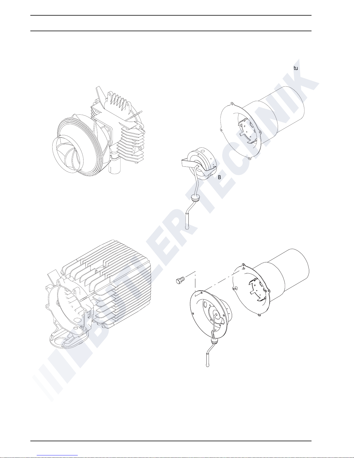
9.2 Disassembly and Assembly............................. .. ..................................... .................. ........................ ..... 903
9.2.1 Housing Components / Covers, Removal ......................... ................................... ....................... 903
9.2.2 Temperature Sensor, Replacement................................................... .................................. ....... 904
9.2.3 Temperature Limiter, Replacement............................................................................................. 904
9.2.4 Control Unit, Replacement.......................................................................................................... 904
9.2.5 Combustion and Heating Air Fan (Drive), Replacement ............................................................. 904
9.2.6 Glow Plug / Flame Sensor, Replacement.................................................................................... 905
9.2.7 Burner, Replacement............ .............................. ............................. .............................. .............. 907
9.2.8 Burner Tube, Replacement .......................................................... .................... ........................... 907
9.2.9 Heat Exchanger, Replacement.................................................................................................... 908
10 Packaging, Storage and Shipping
10.1 General................................................................................................................................................ 1001
List of Figures
Air Top 3500/5000
IV
List of Figures
301 Functional Diagram...................... .................................. ................................... ......................................... 302
501 General Failure Symptoms ............................................................ ................................... ......................... 501
502 Failure Symptoms during Operational Sequence...................................................................................... 502
701 Control Unit Pin Assignment, Air Top 3500/5000 ...................................................................................... 701
702 Automatic Switching Circuit Air Top 3500/5000, 12 V/24 V with Control Element.......................... .. ......... 702
703 Automatic Switching Circuit Air Top 3500/5000, 12 V/24 V with Combination Timer ................................ 703
704 Automatic Switching Circuit Air Top 3500/5000, 12 V/24 V with Combination Timer
and Battery Switch..................................................................................................................................... 704
705 Automatic Switching Circuit Air Top 3500/5000, 24 V ADR Operation with Control Element.................... 705
706 Automatic Switching Circuit Air Top 3500/5000, 24 V ADR Operation
with Control Element and no Auxiliary Drive.............................................................................................. 706
801 Fuel Supply................................................................................................................................................ 802
802 Webasto Fuel Tap............. ................................... .................................. ................................. ................... 803
803 Fuel Tapping from Plastic Tank (tapping via fuel drain plug)..................................................................... 803
804 Fuel Tapping from Plastic Tank (tapping via fitting plate)......................................................................... . 803
805 Pipe/Hose Connection 12 Volt and 24 Volt Installation position horizontal only........................................ 804
806 Dosing Pump, Installation Position ........ .................. .................................. ................................................ 804
807 Fuel Filter................................................................................................................................................... 804
808 Exhaust Muffler, Direction of Flow ................................... ........................ .. ..................... ........................... 805
809 Installation Arrangement of Exhaust Pipe Outlet....................................................................................... 805
810 Removal of the Fuse Holder Mounting Plate ........................................... ................................... ............... 806
811 Fuse Holder Installation Position.................................................................................................... ........... 806
812 Control Element.................................................................................................................. ................ ....... 806
813 Pulling the Connector........................................... .................................. ............................................. .. ..... 806
814 Sample Installation of Air Heater for Air Circulation Mode of Operation................................. .. ................. 807
901 Removal of Housing Components / Covers................................... .. .. ........................................................ 903
902 Disassembly and Assembly............... .................................. ................................... ................................... 906
Air Top 3500/5000
1 Introduction
101
1 Introduction
1.1 Scope and Purpose
This repair shop manual is intended to support
familiarised personnel in the repair of the air heaters
Air Top 3500, Air Top 3500 Volume Plus and
Air Top 5000 of the Diesel type.
1.1.1 Use of the Air Heaters
The air heaters Air Top 3500 and Air Top 5000 are used to
– heat the cabin
– defrost the windscreens
– heat the goods in transport
They are not cleared to be used for heating a
compartment intended for the transportation of dangerous
goods.
The heaters work independently from the vehicle engine
and are connected to the vehicle's fuel and electrical
system. The use in vehicles with water or air cooled
engine is possible.
1.2 Meaning of Warnings, Cautions, and
Notes
WARNINGS, CAUTIONS, and NOTES in this manual
have the following meaning:
WARNING
This heading is used to highlight that non-compliance with
instructions or procedures may cause injuries or lethal
accidents to personnel.
CAUTION
This heading is used to highlight that non-compliance with
instructions or procedures may cause damage to
equipment.
NOTE
This heading is used to highlight and draw specific
attention to information.
1.3 Additional Documentation to be used
This workshop manual contains all information and
procedures necessary for the repair of air heaters
Air Top 3500 and Air Top 5000. The use of additional
documentation is normally not necessary. Operating
instructions/installation instructions and the vehicle
specific installation proposal may be used as
complementary information as necessary.
1.4 Safety Information and Regu lations
The general safety regulations for the prevention of
accidents and the relevant operating safety instructions
have to be observed at all times.
"General Safety Regulations" beyond the scope of these
regulations are detailed in the following.
The specific safety regulations applicable to this manual
are highlighted in the individual chapters by Warnings,
Cautions, and Notes.
1.4.1 General Safety Notes
Within the scope of the StVZO (Road Traffic Licensing
Regulations of the Federal Republic of Germany) "Design
General Approvals" laid down by the Federal Office for
Motor Traffic exist for the Air Heaters Air Top 3500 and
Air Top 5000 with the following official marks of
conformity:
~S306 for Air Top 3500 (Diesel)
~S303 for Air Top 5000 (Diesel)
Installation of the heater is to be performed in accordance
with the installation instructions and must be checked in
case of
a) the vehicle type inspecti on in accordance with
§ 20 StVZO
b) the individual inspection in accordance with
§ 21 StVZO or
c) The examination in accordance with § 19 StVZO
performed by an officially authorised expert or
examiner for road traffic, a vehicle inspector or a
public servant as per section 7.4 a of Annex VIII
to the StVZO.
In the event of c) the installation must be certified on the
acceptance certificate included in the copy of the "General
Operating License" giving details about
– manufacturer
– type of vehicle and
– vehicle identification number.
This validates the "Design General Approval".
The acceptance certificate must be kept with the
vehicle. The year of initial operation must be durably
marked on the identification plate.
The heaters are cleared for heating the passenger and
driver cabin, but not for heating a compartment intended
for the transportation of dangerous goods.
When using the heater in special vehicles (e.g. vehicles
for the transportation of dangerous goods ADR) or in
vehicles not subject to the Road Licensing Regulations
(StVZO) (e.g. ships), the applicable partially regional
regulations must be observed.
1 Introduction
Air Top 3500/5000
102
When installing the Air Top 3500 and Air Top 5000 in
vehicles intended for the transportation of dangerous
goods, the TRS 002 and TRS 003 (Technical Guidelines
for Regulations concerning the transportation of
dangerous goods on roads) must be met in addition to the
StVZO (Road Traffic Licensing Regulations).
The heater must not be installed in the passenger or driver
cabin of busses. Should the heater nevertheless be
installed in such a compartment, the installation box must
be sealed tight against the vehicle inte rior. There must be
sufficient ventilation of the installation box from the
exterior in order not to exceed a maximum temperature of
40 °C in the installation box. Excessive temperatures may
cause malfunctions.
At filling stations and fuel depots the heater must be
switched off as there is a potential danger of
explosion.
Where flammable fumes or dust may build up (e.g. in
the vicinity of fuel, coal, wood, cereal depots, or
similar installations) the heater must be switched off
to prevent explosions.
Due to the danger of poisoning and suffocation the heater
must not be operated, not even with timer, in enclosed
areas such as garages or workshops not equipped with an
exhaust venting facility.
When removing the heater the bottom gasket must be
renewed.
The heat exchanger of the air heater remains
serviceable for a maximum of 10 years and must then
be replaced with an original spare part by the
manufacturer or by one of its authorized wor kshops.
The heater must then be provided with a label
detailing the sales date of the heat exchanger and the
words "original spare part".
When replacing the heat exchanger it is mandatory
to also replace the overheat protection element
(temperature limiter) to avoid possible malfunctions
when using the old temperature limiter.
The heater must be inspected by an expert in time before
the beginning of the heating season.
Should the heater develop strong smoke emissions over
extended periods of time, unusual combustion operating
noise or smell of fuel, the heater must be made
inoperative by removing the fuse and returned into service
only after inspection by Webasto trained personnel.
Claims for warranty may only be made providing evidence
by the claimant that maintenance and safety regulations
have been met.
Ignoring installation instructions and its procedures will
void the warranty by Webasto. The same applies to
unskilled repairs or repairs not using original spare parts.
This will cause loss of the heater's marks of conformity
and thus the vehicle's permit of operation.
1.5 Legal Provisions for Installation
For testing the heater in accordance with § 19, 20, or 21
of the StVZO the following regulations are to be observed
in particular (§ 22 a StVZO):
Testing is performed upon presentation of the operating
and installation instructions of the manufacturer.
The year of the initial operation must be durably marked
on the heater identification plate by the installing person.
Heating Air System
Heating air intake openings must be arranged so that
under normal operating conditions exhaust fumes of the
vehicle engine or air heater are not likely to be sucked in.
Extracting combustion air from the vehicle interior is
prohibited.
Combustion Air Line
The required air for combustion must be taken in from the
exterior.
Within rooms accommodating persons, the combustion
air lines must not have more than four disconnects and a
splash-water protected exterior wall feedthrough. The
disconnects must be sealed in a way not to exceed a leak
rate of 200 l/h at an overpressure of 0.5 mbar.
The line including feedthrough, disconnects, material and
specific type must be described in the installation
instructions.
The line must require tools for installation and removal
and must be protected against damage, and must be
long-time shockproof.
Air Top 3500/5000
1 Introduction
103
Exhaust Line
The heaters must be designed for exhaust emission to the
exterior.
Exhaust lines must be routed so that exhaust fumes are
unlikely to penetrate into the vehicle's interior.
The function of any part of the vehicle essential for
operation must not be impaired. No condensate or water
penetrations may accumulate in the exhaust line. Drain
holes may be provided as required; these must drain the
liquid to the exterior via drain lines sealed against the
vehicle interior.
The exhaust line outlet is to point upwards (with rain
protection), or in case of exhaust venting below the
vehicle floor, to be located at the nearest possible location
of the vehicle's or cockpit side or rear end pointing
downwards.
In compartments accommodating persons, exhaust lines
must not have more than one disconnect and must have
a splash-water protected feedthrough in the exterior wall/
floor. For water, that has penetrated into the exhaust line,
the connection of a drain line with a metal-sealing joint is
permissible. The drain pipe must be routed sealed
through the exterior wall or the vehicle floor.
The heat exchanger, the exhaust line connected, as well
as the possible drain pipe must be sealed so that with an
overpressure double the overpressure of the exhaust
having the maximum permissible exhaust line length – at
least however at an overpressure of 0.5 bar – a total leak
rate of 30 l/h is not exceeded.
The line including feedthrough, disconnects, material and
specific type must be described in the installation
instructions.
The line must require tools for installation and removal
and must be protected against damage, and must be
long-time shockproof.
Metal lines must be used. These may not heat to more
than 110° C should the possibility of body contact exist
within the room interior. Protective devices against body
contact may be fitted.
Should exhaust pipes be routed through rooms
accommodating persons, these pipes shall be renewed
after 10 years using genuine spare parts.
Combustion Air Inlet and Exhaust Outlet
In installations these ports for combustion air entry and
exhaust fume exit must be of such type, that a ball of
16 mm in diameter cannot be inserted.
Electrical lines, switch gear, and control gear of the heater
must be located in the vehicle so that their proper function
cannot be impaired under normal operating conditions.
For the routing of fuel lines and the installation of
additional fuel tanks §§ 45 and 46 of the StVZ O are to be
adhered to.
The most important regulations are: fuel lines are to be
designed in such a way that they remain unaffected by
torsional stresses in the vehicle, engine movement, and
the like. They must be protected against mechanical
damage.
Fuel-carrying parts are to be protected against heat
disturbing operation and are to be arranged so that any
dripping or evaporating fuel can neither accumulate nor
be ignited by hot components or electrical equipment.
In busses fuel lines and fuel tanks may be located neither
in the passenger area nor in the driver's compartment. In
these type of vehicles the fuel tanks must be located such
that they do not pose a direct hazard to the exits in the
event of a fire. Fuel supply must not be by means of
gravity or pressurization of the fuel tank.
Installation Instructions for Webasto Fuel Tanks for
Fuel Supply of Heaters in Vehicles
In busses the installation is not permitted in the
passengers or driver's compartment.
The fuel filler neck must not be located in the passengers
or driver's compartment of any type of vehicle.
The heater operating condition – at least "on" or "off" –
must be clearly visible.
1.6 Corrections and Improvements
Deficiencies, improvements, or proposals for correction of
this workshop manual are to be mailed to:
Webasto Thermosysteme GmbH
Abt. Technische Dokumentation
D-82131 Stockdorf
Telephone: 0 89 / 8 57 94 - 5 42
Telefax: 0 89 / 8 57 94 - 7 57.

1 Introduction
Air Top 3500/5000
104
Page free for notes
Air Top 3500/5000
2 General Description
201
2 General Description
The air heaters Air Top 3500 and Air Top 5000 working to
the evaporator principle of operation basically consist of
the:
– combustion and heating air fan
– heat exchanger
– burner
– combustion tube
– control unit
For control and monitoring the following components are
located inside the air heater:
– control unit
– glow plug / flame sensor
– analogue temperature limiter
– temperature sensor
The heater may be controlled by means of an external
temperature sensor instead of the internal temperature
sensor.
Fuel supply is provided by an external dosing pump.
In case of a heater malfunction an error code is output to
the display of the combination timer. When equipped with
a control element, the operating indicator light will flash.
The heater may be additionally checked using a personal
computer (refer to operating instructions for PC heater
fault diagnosis).
Air Heater Air Top 3500/5000
2 General Description
Air Top 3500/5000
202
2.1 Combustion and Heating Air Fan
The combustion and heating air fan delivers the air
necessary for combustion from the combustion air inlet
into the burner. The fan also supplies heating air to the
heating air outlet.
2.2 Heat Exchanger
Within the heat exchanger the air delivered by the
combustion and heating air fan is charged with the heat
generated by combustion.
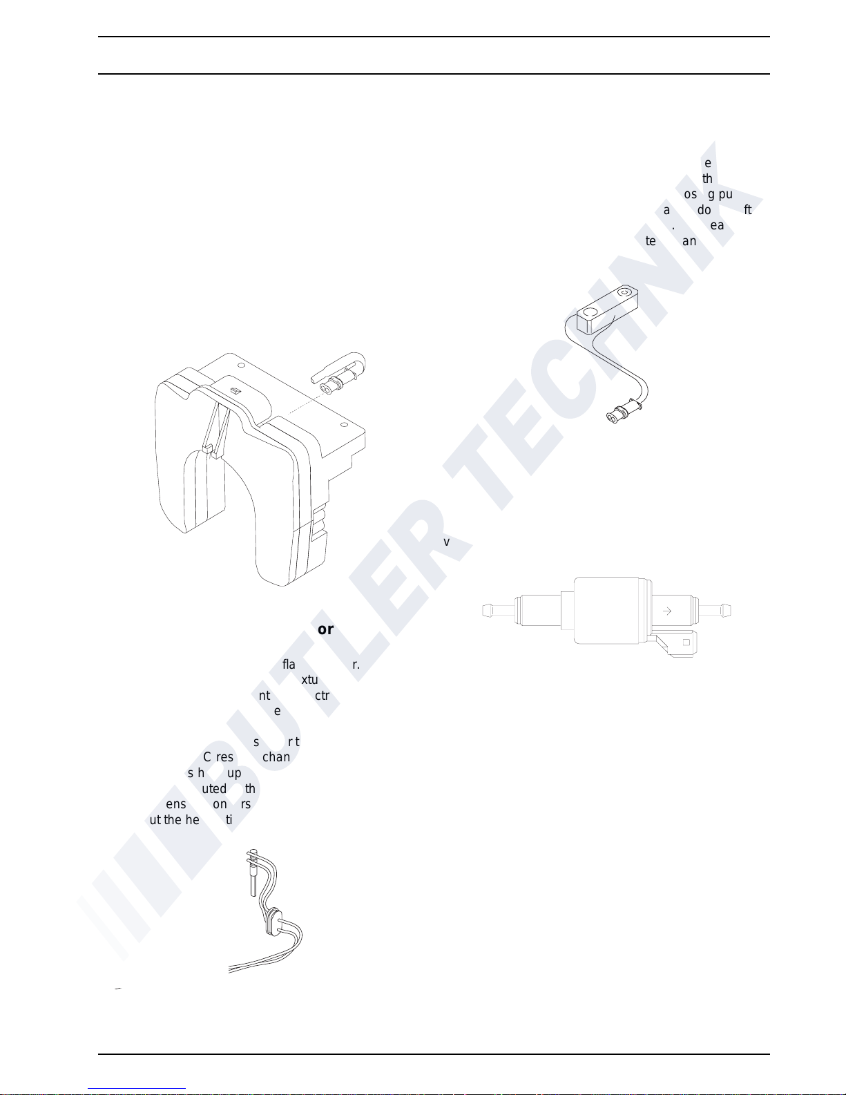
2.3 Burner with Combustion Tube
Inside the burner insert fuel is distributed across the
combustion tube fuel cross section. Combustion of the
fuel/air mixture takes place within the combustion tube to
heat the heat exchanger.
or
Combustion tube
Burner
Combustion tube
Burner with shield
Air Top 3500/5000
2 General Description
203
2.4 Control Unit
The control unit ensures control and monitoring of
combustion operation. A temperature sensor plugged on
the control unit is used for temperature control. On all
heaters this temperature sensor may be substituted with
an externally mounted temperature sensor.
In case of a heater malfunction an error code is output
to the display of the combination timer. When equipped
with a control element, the operating indicator light will
flash.
The heater may be additionally checked using a personal
computer (refer to operating instructions for PC heater
fault diagnosis).
2.5 Glow Plug / Flame Sensor
The glow plug also functions as flame sensor.
The glow plug ignites the fuel/air mixture during heater
start. The glow plug represents an electrical resistance
and is located on the side of the burner exposed to the
flame.
When operating as a flame sensor the glow plug behaves
like a low Ohm PTC resistor changing its resistance
dependent on its heat-up by the flame.
The signals are routed to the control unit for processing.
The flame sensor monitors the flame-up condition
throughout the heater time of operation.
2.6 Analogue Temperature Limiter
The analogue temperature sensor protects the heater
against undue high operating temperatures. For
protection against overheating the temperature limiter
responds at a heating air temperature higher than
150° C. The control unit disconnects the dosing pump
circuit and deactivates the heater with a run-down. After
cooling down the circuit is re-established. The heater may
be reactivated by switching the heater off and on again
using the control element.
2.7 Dosing Pump
The dosing pump is a combined delivery, dosing and
shut-off system for the fuel supply of the heater out of the
vehicle fuel tank.
2 General Description
Air Top 3500/5000
204
Page free for notes
Air Top 3500/5000
3 Functional Description
301
3 Functional Description
(Fig. 301)
3.1 Control Element
The control element is used to switch the heater on and
off, to set the desired room temperature (air intake
temperature between 5° C and 35° C), to reset the heater
after a malfunction with error lockout and to adjust the
CO
2
value.
The integrated green LED indication is used as
• operating indicator light (LED permanently on)
• error code/overheat indicator (LED flashes)
NOTE
Only applicable to ADR operation!
When applying electrical power with the control element
still set to "on", e.g. by closing the battery switch, the
control unit will go in error lockout. For re-activation the
control element must be momentarily switched off and on
again.
3.2 Switch on
The control element is to be set to the desired
temperature. When switching the heater on the operating
indicator light will illuminate. The motor of the combusti on
and heating air fan runs up at low speed.
NOTE
If the temperature of the combustion air taken in exceeds
the set temperature, the heater will enter control idle. With
the combustion air temperature below the set
temperature, the starting sequence commences.
The function of the glow plug/flame sensor is checked.
Should the glow plug/flame sensor already signal at this
stage "bright" for longer than 60 seconds, there will be a
150 second run-down and an error lockout of the control
unit. A malfunction of another component monitored
causes an error lockout without run-down.
Start
The glow plug/flame sensor is activated. After
approximately 22 seconds the dosing pump is put into
operation and combustion commences. After
116 seconds the glow plug is deactivated and the flame
sensor becomes active. After 136 seconds a check is
performed to verify a proper burning of the flame.
Detection of a flame will cause the flame to be stabilised
for 50 seconds by burning at 1.5 kW.
No flame detection will initiate a repeat start.
2nd Start (Repeat Start)
For this purpose the dosing pump is switched off and the
glow plug is activated. After 40 seconds the dosing pump
is reactivated.
After another 40 seconds the glow plug is deactivated and
20 seconds later the flame is checked. Detection of a
flame will cause the flame to be stabilised for
approximately 50 seconds by burning at 1.5 kW.
Should flame detection at that time be still negative, there
will be a run-down of the combustion and heating air fan
at full speed (approx. 5000 rpm) with an error lockout after
180 seconds.
NOTE
After the first repeat start the heater enters an error
lockout condition. For error lockout reset the heater must
be switched off (at least for 2 seconds) and switched on
again.
3 Functiona l Description
Air Top 3500/5000
302
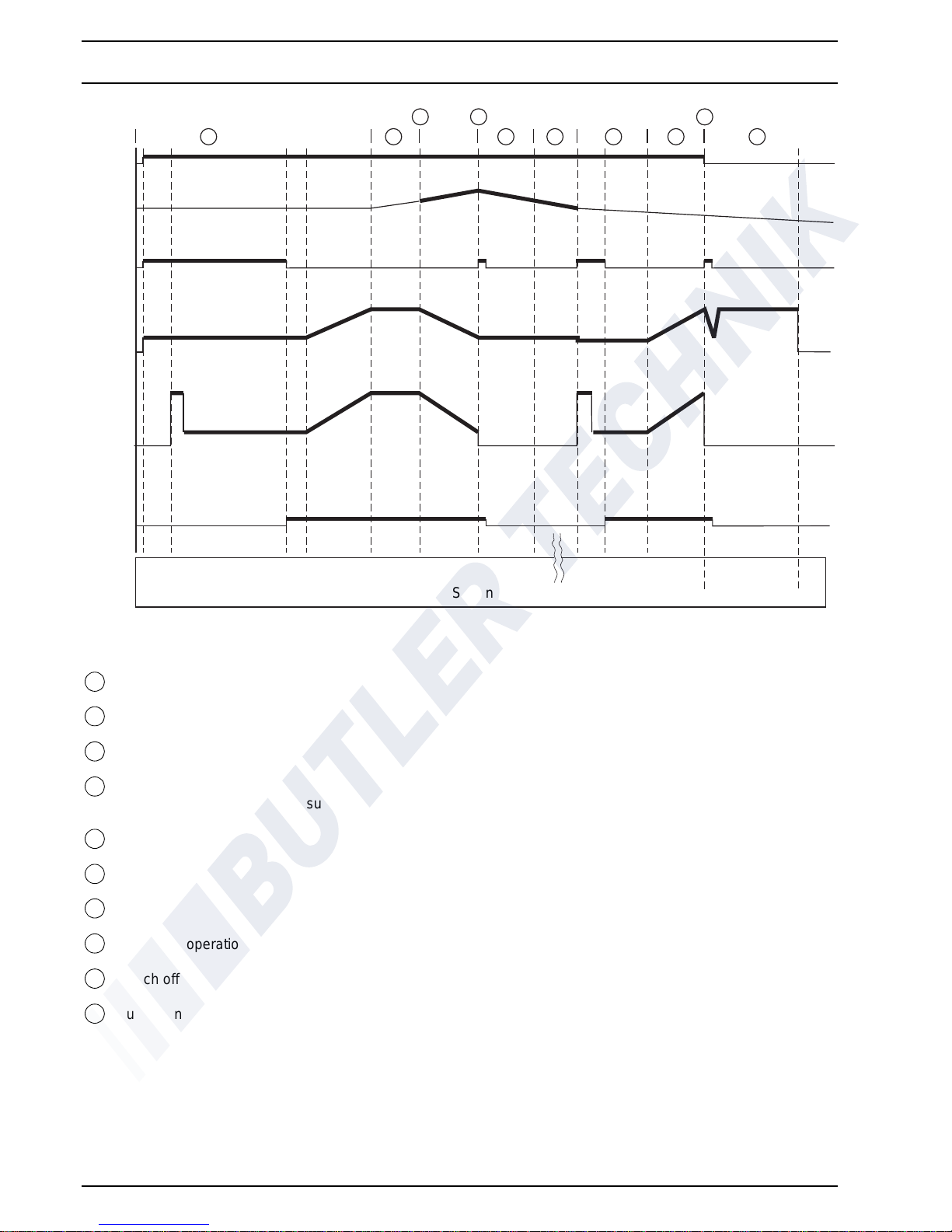
1Start
2 Controlled operation
3 Rated (set) value achieved
4 Rated (set) value exceeded
(e.g. due to reduced heat consumption)
5 Run-down
6 Control id le
7Start
8 Controlled operation (increased heat consumption)
9 Switch off
10 Run-down
A
= Control element
B
= Temperature sensor
C
= Glow plug
D
= Combustion and heating air fan
E
= Dosing pump
F
= Flame sensor
Fig. 301 Functional Diagram
Ein
A
0
1
1 2
3 4
5 6 7 8
9
10
B
C
0
1
100%
90%
60%
30%
0
D
2,0 (2,8)* Hz
0,5 Hz
0
E
F
0
1
020
116
124
174
Sekunden
(180)
*) AT5000
Seconds
on
on
 Loading...