

Page 1

WARNING!
Hazard warning:
Incorrect installation or repair of Webasto heating systems may cause a fire or result
in the emission of carbon monoxide, which can be fatal. Serious or fatal injuries can
be caused as a result.
Specialist company training, technical documentation, specialized tools and
equipment are required to install and repair Webasto heating and cooling systems.
NEVER attempt to install or repair Webasto heating or cooling systems if you have not
successfully completed the company training and thereby acquired the required
technical skills, or if you do not have access to the required technical document ation,
tools and equipment needed to carry out correct installation and repairs.
ALWAYS follow all Webasto installation and repair instructions and observe all
warnings.
Webasto does not accept any liability for defects and damage that are attributable to
installation by untrained staff.
Feel the drive
Renault Master/Nissan Interstar
Diesel
from Model Year 2004
Left-hand drive vehicle
Vehicles without partition wall
ID No.:1312624C_EN Fee Euro 10 © Webasto AG
Air Heater Unit
Air Top 3500 ST D Additional Heater
Installation Instructions
e1
00 0015
Page 2
22
Renault Master/Nissan Interstar
Validity 2
Heater Unit/Delivery Scope 3
Foreword 3
General Instructions 3
Special Tools 3
Explanatory Notes on Document 4
Preliminary Work 5
Heater unit installation location 5
Preparing installation location 6
Preparing heater unit 7
Installing heater unit 7
Preparing hot air ducting 8
Preassembling hot air ducting 9
Installing hot air ducting 9
Installing hot air distribution 10
Recirculating air intake 12
Exhaust system 14
Combustion air 15
Fuel Connection 16
Electrical Connections 19
Connection Diagram for Combination Timer and
Telestart 20
Heater control option 21
Remote option (Telestart) 22
Installing trim parts 23
Final Work 24
Template for Heater Unit 25
Table of Contents
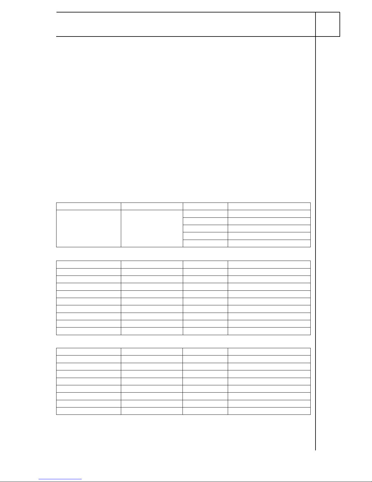
Validity
Manufacturer Model Type EG-BE No./ABE
Nissan Interstar J3 e2 * 2001 / 116 * 273
F3 L223
U3 L414
E3 N004
N3 L226
Manufacturer Model Type EG-BE No./ABE
Renault Master JD e2 * 98 / 14 * 0129
ED H914
FD H912
GD K150
HD K149
UD H913
ND K309
PD K535
RD K535
Engine type Engine model Output in kW Displacement in cm³
F9Q Diesel 60 1870
G9T Diesel 66 2188
G9T Diesel 84 2188
G9U Diesel 73 2463
G9U Diesel 74 2463
G9U Diesel 88 2463
G9U Diesel 107 2463
ZD3 Diesel 100 2953
Page 3
33
Renault Master/Nissan Interstar
Heater Unit/Delivery Scope
Optional heater control either:
Foreword
These installation instructions apply to Renault Master/Nissan In terst ar vehicles with a Diesel engine
- for validity, see page 2 - from model year 2004 and later, assuming technical modifications to the
vehicle do not affect installation, any liability claims excluded. Depending on the version and the
equipment variants of the vehicle, changes may be necessary relative to these "installation
instructions" during installation and must be adjusted accordingly.
However, where this is the case the stipulations in the "installation instructions" and "operating and
maintenance instructions" for the Air Top 3500 ST should be observed.
The corresponding rules of technology and any information from the vehicle manufacturer should be
observed during the installation work.
The installation location of heater controls and the ro uting of the air ducting part s must be coor dinated
with the final customer prior to installation!
WARNING!
Original load-bearing components of the vehicle and/or component used for crash safety may not be
modified for the hot air and recirculating air ducting!
General Instructions
Installation should be carried out according to the general, standard rules of technology. Unless
specified otherwise, fasten hoses, lines and wiring harnesses to original vehicle lines and wiring
harnesses using cable ties.
Sharp edges should be fitted with edge protectors (split-open plastic hose).
Spray unfinished body areas, e.g. drilled holes, with anti-corrosion wax (Tectyl 100K, Order No.
111329).
Special Tools
- Metric thread-setter kit
- Hole circle bit 83 mm dia.
- Hole circle bit 92 mm dia.
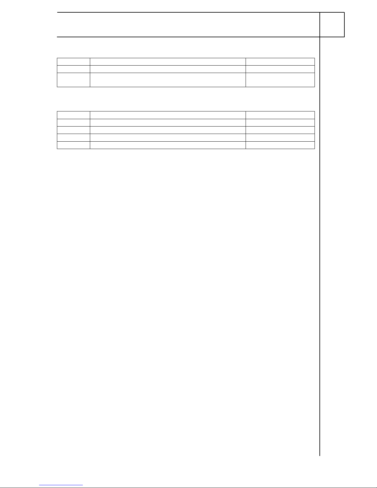
Quantity Description Order No.:
1 Delivery scope of AT 3500 ST D 12V with heater control 9008944A
1 Installation kit Renault Master / Nissan Interstar Diesel
AT3500ST
1312622B
Quantity Description Order No.:
1 Digital timer (combination 12 V) 9010385A
1 Mounting plate for digital timer (frame) 474630
1 Telestart (only in conjunction with combination timer) See price list
1 Y-cable for combination timer - Telestart 1311194A
Page 4
44
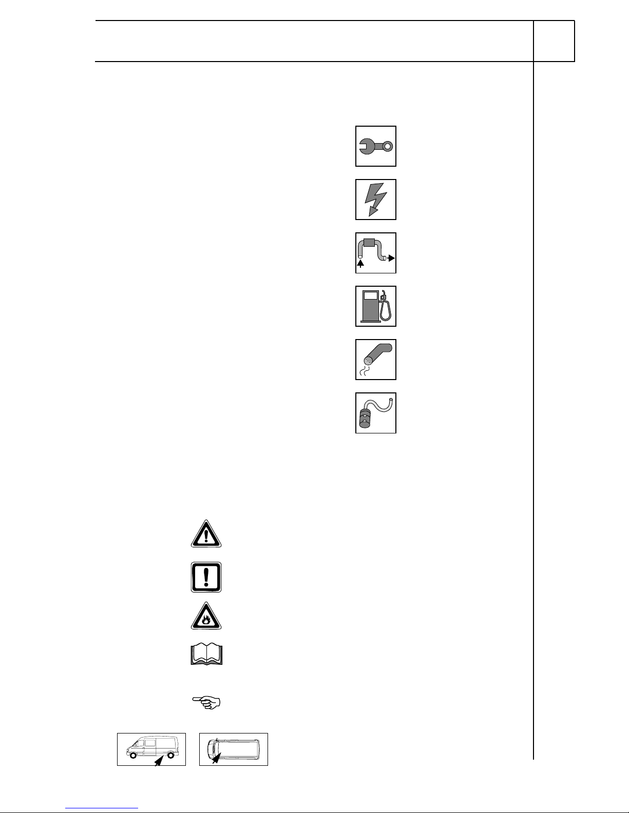
Special features are highlighted us ing the following symbols:
Mechanical work
Electrical system
Hot air system
Fuel connection
Exhaust system
Combustion air
The arrow in the vehicle icon indicates the position on
the vehicle and the
viewing angle.
Renault Master/Nissan Interstar
Specific risk of injury or fatal accidents.
Specific risk of damage to components.
Specific risk of fire or explosion.
Reference to general installation instructions of
Webasto components or to the manufacturer's vehiclespecific documents.
Reference to a special technical feature.
i
Explanatory Notes on Document
T o provide you with a quick overview of the individual working steps, you will find an identification mark
on the outside top right corner of the page in question.
Page 5
5
Renault Master/Nissan Interstar
Heater unit installation location
1 Heater unit
Installation
location
1
1
Preliminary Work
WARNING!
- Disconnect the battery "earth" or "ground" connection.
- Copy the factory number from the original type label to the duplicate type label.
- Remove years that do not apply from the duplicate label.
- Attach the duplicate label (type label) in the appropriate place.
- If installed, remove the rear seat row behind the driver's seat
- If installed, remove the floor covering behind the driver's seat
- Remove the trim of the A-pillar on the driver's side
- Remove the sun vizor on the driver's side
- Remove the front left side trim in the cargo space (only with cargo space trim)
Page 6
6
Renault Master/Nissan Interstar
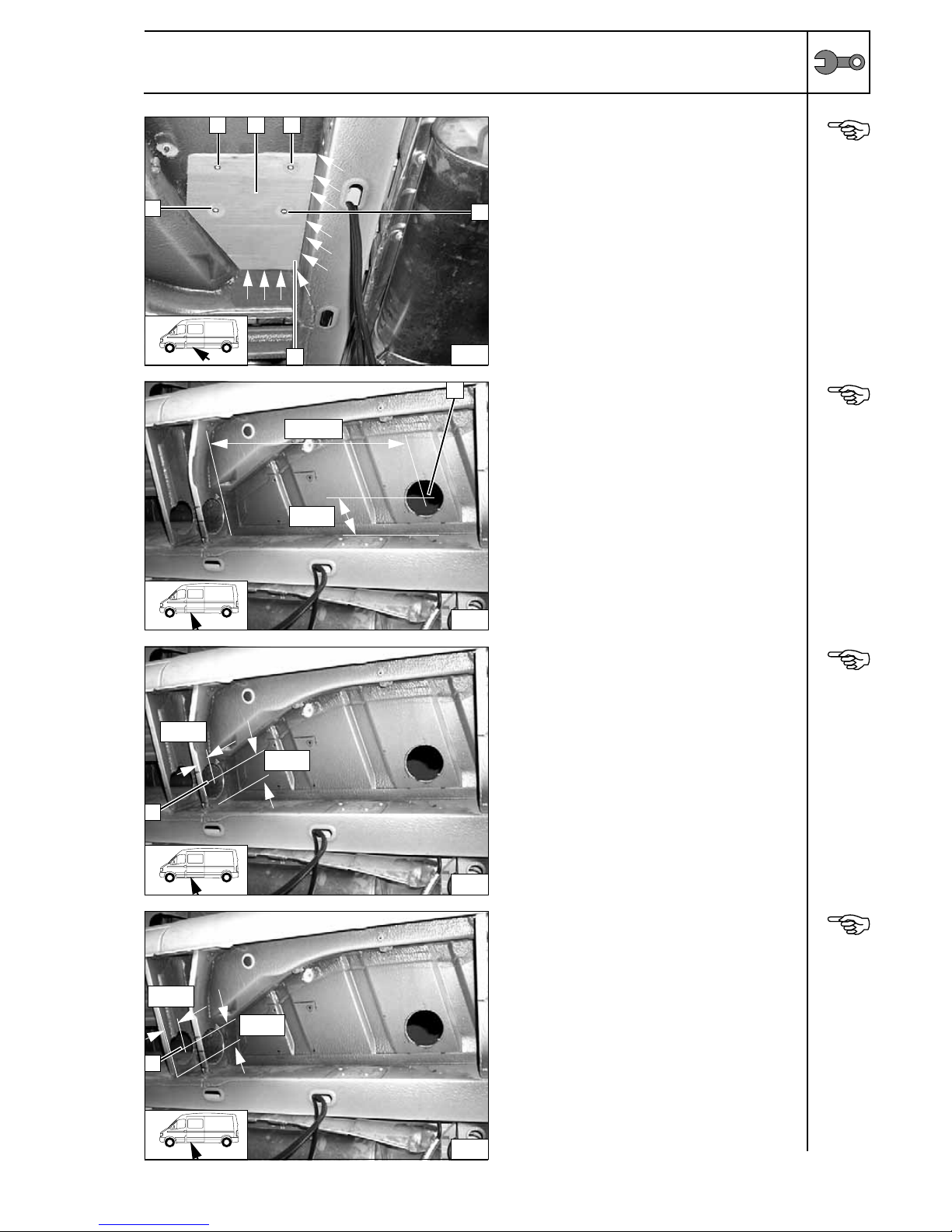
Preparing installation location
Lay on drilling template 2 provided exactly;
remove underbody protection in corners as
shown (arrows) if necessary. Holes may not
be located in area of beads.
1 Copy hole pattern, drill 7 mm hole [4x] in
floor panel
Copying
hole
pattern
Reapply underbody protection.
1 83 mm dia.hole in floor panel
Hole in
floor panel
Drill opening so that only horizontal bar is left
in place.
1 92 mm dia. hole in floor panel
Hole in
floor panel
Ensure sufficient corrosion protection for all
holes.
1 92 mm dia. hole in floor panel, install edge
protection
Hole in
floor panel
2
1
1 2
6
1
1
85 mm
535 mm
3
1
46 mm
70 mm
4
1
60 mm
65 mm
5
1
Page 7
7
Renault Master/Nissan Interstar
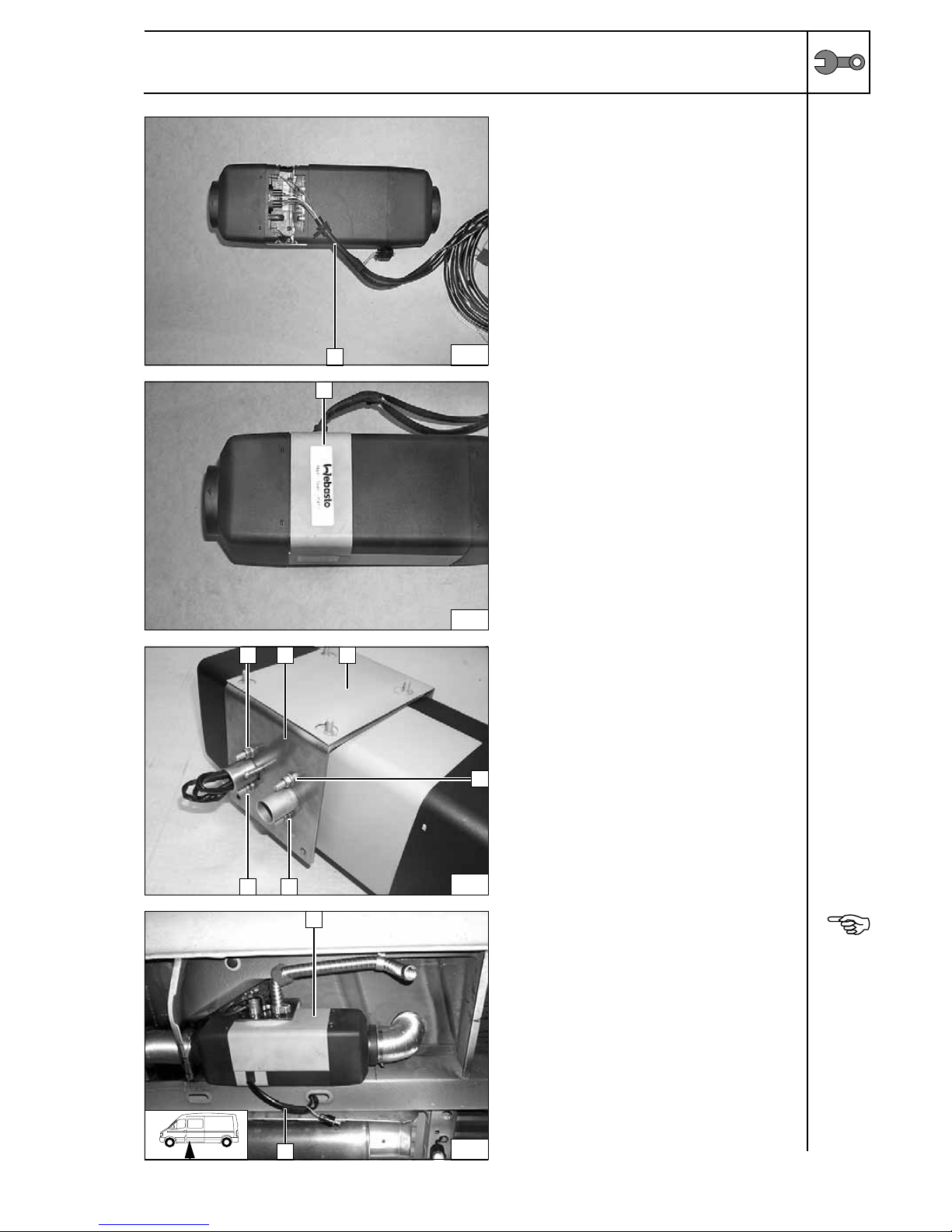
Preparing heater unit
1 Push on wiring harness
Connecting wiring
harness
1 Mount cover offset by 180°
Installing
cover
2 Bracket of heater unit
1 Washer, self-locking nut [4x each]
3 Loosely lay on bracket for splash
protection
Installing
bracket
Installing heater unit
Fasten preassembled heater unit 1 to
underbody with 4 self-locking M6 nuts and 4
large diameter washer.
Remove red (rt) wire in wiring harness to fuse
holder on blade-type fuse holder.
Route wiring harness of fuse and
digital/combination timer 2 in frame side
member along frame side member to battery
box.
Insert red (rt) wire again on fuse holder.
Fasten wiring harness with cable ties.
Installing
heater unit
6
1
7
1
8
1
1 2
1
1
3
9
1
2
Page 8
8
Renault Master/Nissan Interstar
Preparing hot air ducting
2 Insert pass through into existing opening
1 Copy hole pattern, drill 4.5 mm hole [4x]
Preparing
pass
through
2 Insert pass through in existing opening and
seal off with sealing compound
1 M4x12 bolt [4x], washers [8x], M4 flanged
nut [4x]
Installing
pass
through
1 Position kick guard
2 Copy hole pattern for 9.1 mm hole [4x]
Lay on kick
guard
1 Drill out hole to 9.1 mm dia., mount rivet nut
[4x each]
Installing
rivet nut
10
1 1
1
2
1
1 1
1
2
1
11
12
2
1
2
2
2
1 1
1
1
13
Page 9

9
Renault Master/Nissan Interstar
Preassembling hot air ducting
A 80 mm dia. flexible tube
a = 125 mm
B 80 mm dia. flexible tube
a = 125 mm
C 80 mm dia. flexible tube
b = 120 mm
F 80 mm dia. flexible tube (for recirculating
air)
f = 385 mm
X Discard section
Cutting
flexible
tube to
length
Fasten flexible tube with hose clamps as
shown.
1 80/60/60/80 branch
A 125 mm flexible tube cut to length
2 80/55 reducer
B 125 mm flexible tube cut to length
Installing
pass
through
Installing hot air ducting
Mount preassembled hot air ducting on pass
through 1 and fasten with hose clamp. When
doing so, align 80/60/60/80 branch 2 as
shown.
Installing
hot air
ducting
a
A
B
B
F
FC
C
X
1 B
2
14
A
15
1 2 A
B
Page 10

10
Renault Master/Nissan Interstar
D 400 mm PAK pipe
1 90° hot air elbow
Preassembling distribution
E 200 mm PAK pipe
1 90° hot air elbow
2 60/60/60 distributor
Preassembling distribution
Installing hot air distribution
Insert preassembled hot air distribution D into
existing opening 3 with 90° hot air elbow first
and route to left-hand opening 1.
Insert preassembled hot air distribution E into
existing opening 3 with 60/60/60 distributor
first and push onto preassembled hot ai r
distribution D as far as possible.
On vehicles without side trim:
Push preassembled hot air ducting A/B with
80/55 reducer onto distributor 2.
Drill 2.5 mm hole through reducer and
distributor. Connect reducer and distributor
with self-tapping screw.
Installing
distribution
1 D
16
1 E
17
2
1 2
18
3
D
EA/B
Page 11

11
Renault Master/Nissan Interstar
On vehicles with side trim:
The dimensions 40 mm and 60 mm are
specifications for a side panel that reaches
down to the floor panel.
Should a side panel be installed tha t does not
reach down to the floor panel, these
dimensions must be calculated in accordance
with the distance to the floor panel.
Cut out side trim as shown
Cutting out
side trim
Mount side trim. Push preassembled hot air
ducting A/B with 80/55 reducer onto
distributor 1.
Drill 2.5 mm hole through reducer and
distributor. Connect reducer and distributor
with self-tapping screw.
Preassembling distribution
All vehicles
Shorten connection piece from air outlet by
approx. 10 mm on vehicles without side trim.
Mount cover piece 2 on air outlet 3. Mount air
outlet 3 with cover piece 2 on each hot air
elbow. Drill 2 2.5 mm dia. holes 1 each
through reducer and distributor. Connect
reducer and distributor with self-tapping
screw.
Installing
air outlet
When drilling, watch components located
behind!
Copy hole pattern 1 from cover piece 3 to side
panel or trim in each case.
Copy hole pattern 2 from air outlet 4 to cover
piece 3 in each case.
1 2.5 mm dia. hole, self-tapping screw
[4x each]
2 2.5 mm dia. hole, self-tapping screw
[3x each]
Installing
air outlet
19
78080
80 320
90
30
90
80
40*
60*
1
20
A/B
1
3
21
1
2
1
1
22
1
3
122
2
4
Page 12

12
Renault Master/Nissan Interstar
Mount rotating air outlet grid 1 [2x] on air
outlet and engage.
Installing
grids
Shape 120 mm long flexible tube C as shown,
mount on heater unit hot air outlet and on
pass through and fasten with hose clamps.
Installing
flexible
tube
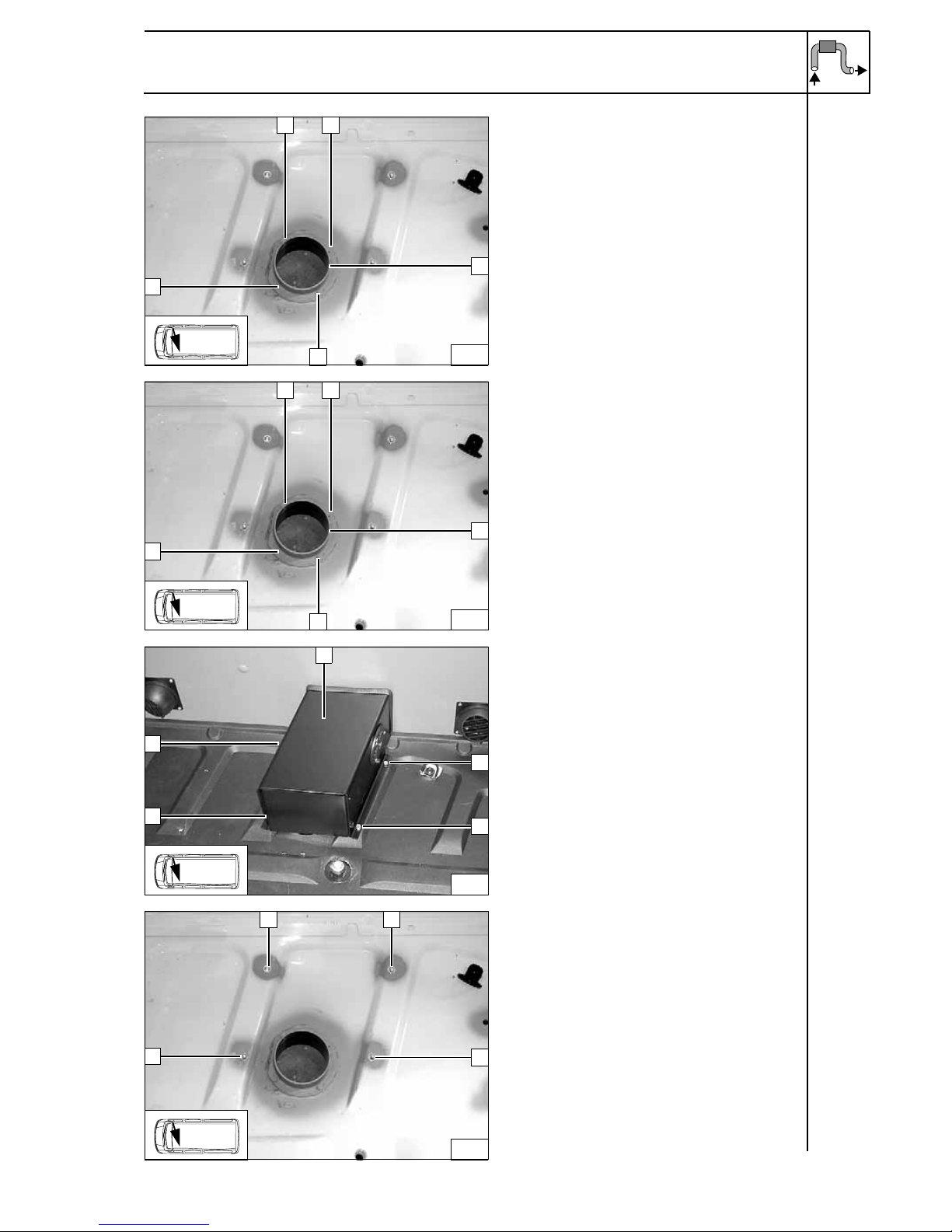
Recirculating air intake
Remove entrance trim on driver's side.
Flatten beads in metal sheet in area of pass
through with flattening tool.
Ensure sufficient corrosion protection for all
holes.
1 83 mm dia. hole in entrance trim of driver's
side and in metal sheet behind it
Hole in
floor panel
Seal off pass through from behind with
sealing compound.
1 Insert pass through in 83 mm dia. hole
2 2.5 mm dia. hole, self-tapping screw
[3x each] in entrance trim
Installing
pass
through
1
23
1
C
24
120 mm
85 mm
1
25
26
1
2
2
2
Page 13

13
Renault Master/Nissan Interstar
Mount air outlet grid 1 on pass through and
engage (close off flush toward outside)!
Installing
grid
Mount hot air elbow 90° 1 on pass through 3,
align downward and fasten with 3 self-tapping
screws 2.
Hole in
floor panel
Guide 385 mm long flexible tube F through
prepared hole, mount on heater unit inlet and
on hot air elbow and fasten with hose clamps.
Installing
flexible
tube
27
1
3
28
21
F
29
Page 14

14
Renault Master/Nissan Interstar
Exhaust system
1 Exhaust pipe
a = 450 mm
Discard section X
Preparing
exhaust
pipe
3 Exhaust pipe
1 Hose clamp
2 Push on red (rt) rubber isolator and
position
4 P-clamp, M6x20 bolt on existing threaded
hole
5 Shape end section as shown
Installing
exhaust
pipe
a
X 1
30
1
2
5
34
Page 15

15
Renault Master/Nissan Interstar
Combustion air
1 Combustion air pipe
a = 450 mm
Discard section X
Preparing
combustion air
pipe
Guide wiring harness of metering pump
through groove in combustion-air intake
connection piece.
Mount combustion-air intake pipe 1 on
combustion-air intake connection piece and
fasten with hose clamp.
Drill 4 mm dia. hole in frame side member at
position 2. Route combustion-air intake pipe
1 as shown and fasten on frame side member
with p-clamp and self-tapping screw 2.
Mount end cap 3 on combustion-air intake
pipe.
Installing
intake pipe
Note:
When using a Webasto water heater and a
Webasto air heater together , the exhaust pipe
of the water heater must be routed along the
left-hand side sill.
Ensure sufficient spacing between the
exhaust pipe of the water heater and the
combustion-air intake pipe of the air heater.
a
X 1
31
3
1
2
i
Page 16

16
Renault Master/Nissan Interstar
Fuel Connection
CAUTION!
Open the vehicle's fuel tank cap, ventilate the tank and then re-close the tank lock.
Catch any fuel running off with an appropriate container.
Install fuel line and metering-pump wiring harness so that they are protected against stone impact.
Unless specified otherwise, always fasten using cable ties.
Mount the fuel line and wiring harness with rub protection on sharp edges.
WARNING!
The fuel line and wiring harness are routed to the metering pump in as shown in the wiring harness
routing diagram.
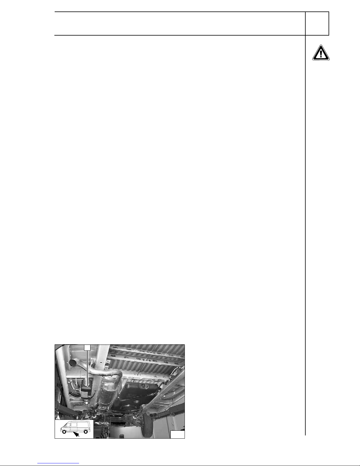
Ensure proper installation position of
metering pump 1, see "Installation
Instructions“.
Remove original vehicle screw of fuel-tank
line bracket and discard. Insert silent block
into threaded hole.
Fuel line from heater unit 4 on pressure side
of metering pump [side with connector].
2 Rubber-coated p-clamp, flanged nut on
silent block
3 Hose section, 10 mm dia. hose clamps [2x]
5 Wiring harness of metering pump, single-
wire seal, tab connector, connector
housing
Installation
location of
metering
pump
Route Mecanyl fuel line and wiring harness of
metering pump along right-hand frame side
member to cross member and fasten to
existing clips of brake lines. Cut off 1,200 mm
of protective hose provided. Install Mecanyl
fuel line together with wiring harness of
metering pump in 1,200 mm protective hose.
Installing
lines
Route Mecanyl fuel line and wiring harness of
metering pump in protective hose 3 in cross
member behind fuel tank to left-hand side of
vehicle. When doing so, route protective hose
past parking brake guide by routing out
through openings in cross member and then
back in again. Insert cut-open protective
rubber plugs in both openings 1. Fasten
protective hose with cable ties 2 [2x] as
shown.
Installing
lines
32
4
1 2
5
3
i
33
1 2
3
12
Page 17

17
Renault Master/Nissan Interstar
Route protective hose 1 out of cross member
as shown and pull wiring harness of metering
pump into frame side member together with
Mecanyl fuel line.
Installing
lines
Route wiring harness of metering pump out of
frame side member together with Mecanyl
fuel line as shown. Push remaining 300 mm
long piece of protective hose 1 onto wiring
harness of metering pump and Mecanyl fuel
line. Route protective hose over hood of
heater unit to fuel inlet of heater unit.
Installing
lines
Ensure sufficient spacing of Mecanyl fuel line,
wiring harness of metering pump and
protective hose to exhaust pipes and to hot
air outlet.
3 90° molded hose
1 Mecanyl fuel line in protective hose
2 10 mm dia. hose clamps [2x]
4 Wiring harness of metering pump, single-
wire seal, tab receptacles, connector
housing
Connection on
heater unit
34
1
35
1
36
2 3
2
1
4
Page 18

18
Renault Master/Nissan Interstar
Cut off fuel return line as shown.
1 Fuel return line, 8 mm dia. hose clamps
[2x]
4 Fuel standpipe
2 Remaining end of Mecanyl fuel line
3 Hose section, 10 mm dia. hose clamps
[2x].
Removing
fuel
Fuel line from fuel standpipe 1 on intake side
of metering pump [side without connector].
Check the position of the components; adjust
if necessary. Check that they have free
clearance.
2 Hose section, 10 mm dia. hose clamps
[2x].
Connection to metering
pump
3737
1
3 2
4
38
1 2
Page 19

19
Renault Master/Nissan Interstar
Electrical Connections
Fuse holder
4 2.5 mm dia. hole, retaining plate for fuse
holder, 3.5x13 self-tapping screw
3 Fuse holder mounted
2 Ground wire on negative battery terminal
1 Positive wire on positive battery terminal
Wiring routing
Route wiring harness of heater unit from
underbody through existing opening in battery
box (rear left).
Route wiring harness of digital timer 1 under floor
cover to center console.
Wiring
harness
installation
diagram
Connection to lighting of digital timer
Make connections as shown in wiring diagram
with blade connectors provided.
1 Light blue (hbl) wire from parking light switch
(terminal 58)
2
Gray (gr) wire from preassembled wiring harness
39
4
31 2
40
1
gr
br
bl
i
41
1
2
1
Page 20

20
Renault Master/Nissan Interstar
Connection Diagram for Combination Timer and Telestart
Connection Diagram for
Combination Timer
Connection Diagram for
Combination Timer
+ Telestart
Components of Cable colors Symbols
Legend
HG Heater unit rt red
*
Connectors not used!
TE Telestart receiver gr gray
VWU Digital timer sw black "Potentiometer“
connector!
br brown
hbl light blue X Connect identical colors
of connectors!
9006887C
X
9004312D
VWU
HG
(AT3500ST)
15A
5A
sw rt
gr
br
terminal 58
hbl
br
rt
rt
*
*
!
9006887C
X
9004312D
VWU
HG
(AT3500ST)
15A
5A
sw rt
gr
br
terminal 58
hbl
br
rt
rt
br
rt
X
X
TE
1311194A
(1311677A)
67089A
**
!
*
Page 21

21
Renault Master/Nissan Interstar
Digital/combination timer
Use installation frame 2 as template. Copy
hole pattern [2x] for screwing on and cutout to
center console
1.
Cut out 2 4 mm dia. holes in center console
and hole pattern for combination timer insert
Preparing
combination timer
1
Combination timer
Installing
combination timer
Heater control option
1 12 mm dia. hole, heater control in center
console
Installing
heater
control
1
2
42
i
1
43
1
44
i
Page 22

22
Renault Master/Nissan Interstar
Remote option (Telestart)
3 Bracket, align as shown
2 Original vehicle bolt
1 Receiver
Installing
receiver
1
Antenna
Installing
antenna
Temperature sensor for HTM100 only
1
Fasten temperature sensor with suitable
means
Installing
temperature sensor
1
45
23
i
1
46
1
47
Page 23

23
Renault Master/Nissan Interstar
Installing trim parts
2 Kick guard
1 Edge protection
4 Outlet screen on both sides [2x]
3 2.5 mm dia. hole, self-tapping screw
3.5x13 [3x each]
Preparing
kick guard
1
Kick guard
2 M6x16 bolt [4x] on prepared rivet nuts
Installing
kick guard
3
Heater unit trim
2 Mount M6x12 bolt, spring lockwasher
[2x each] on rivet nuts
1 Drill out 4 mm dia. hole, self-tapping screw
5.5x13; spring lockwasher [2x each]
Installing
heater unit
trim
2
Heater unit trim
1 Flanged nut [2x] on existing stud bolt
Installing
heater unit
trim
1
48
2
3
3
4
3
49
2
2
1
2
2
2
50
21
1
3
1
51
2
1
Page 24

Renault Master/Nissan Interstar
Webasto AG
Postfach 80 - 82132 Stockdorf, Germany - Hotline +49(0)1805-932278
Hotfax +49-(0)395-5592-353 - http://www.webasto.de
Feel the drive
Final Work
WARNING!
Reassemble the disassembled components in reverse order.
Check all hoses, hose, spring and Caillau clamps, as well as all electrical connections for firm seating.
Secure all loose cables using cable ties.
Spray the heater unit components with anti-corrosion wax (Tectyl 100K, Order No. 111329).
- Connect the battery
- Set the digital timer, teach the Telestart if installed
- Check the proper operation of the air heater, see the operating instructions/installation
instructions.
- Attach the "Switch off additional heater before refueling" sticker to the left-hand B-pillar.
i
Printed in Germany 06/08Printed by: Steffen
Page 25

25
0
100 mm
100 mm
Scale 1:1
Compare the size of the printed version with dimen sion lines.
Permitted tolerance a maximum of 2%.
Correct major differences in the printer settings or request an
original printout.
Ø 7mm Ø 7mm
Ø 7mm
Ø 7mm
Template for Heater Unit
Renault
 Loading...