

Webasto AIR TOP 2000 ST EVO, AIR TOP 3900 EVO, AIR TOP 5500 EVO Installation And Operation Instructions
Page 1
Note:
(Optional Step)
Note:
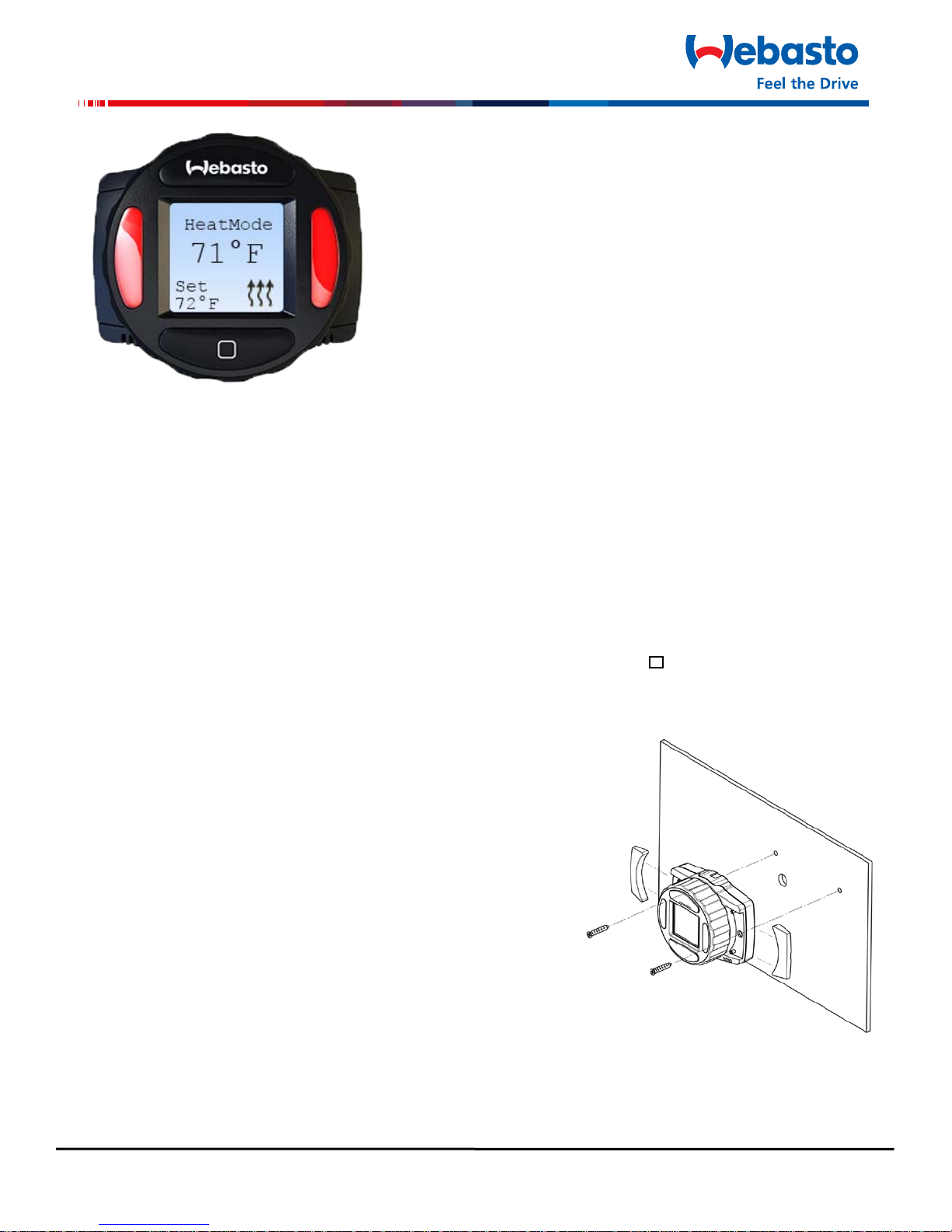
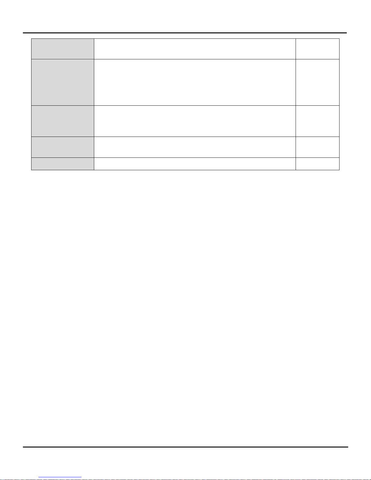
SmarTemp Control
Digital Control Interface For
Air Top 2000 ST / 3900/5500 EVO Heaters
Installation / Operation Instructions
English ……………………………………………………………………………………………………..1
Français ……………………………………………………………………………………………….……6
Español ……………………………………………………………………………………….……....…..13
General
Thank you for choosing Webasto to meet your heating needs. The Webasto SmarTemp Control enables
you to quickly and effortlessly operate the AT 2000 ST or AT 3900 / 5500 EVO Air Heaters.
Operation
The Webasto SmarTemp Control can be operated using a single rotary dial around the outside of the unit
to browse through different menu options. Simply click the select button ( ) to make your choice. The
following sections will define each menu item and its default setting.
Compatibility
AT 2000 ST - Adaptor harness (P/N: 5010612)
AT 3900 / 5500 EVO – Adaptor harness (P/N: 5012138)
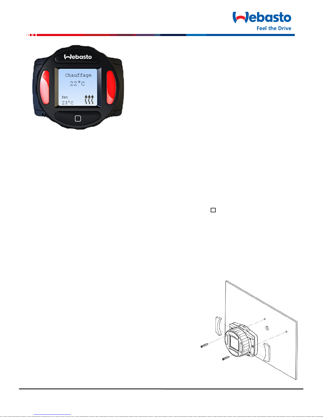
Mounting Procedure
1. Find a suitable mounting location (on a flat surface if
possible) in a visible area.
effects of weather and contamination.
2. Use the drilling dimensions / template in the back of
this manual to lightly mark the two mounting holes.
3.
mounting surface, drill a 22mm hole as notated on the
drilling dimensions / template.
the mounting location prior to drilling.
4. Secure the Webasto SmarTemp Control using the two supplied #4 screws.
Always install in an area protected from the
To route wire harness through the
Always make sure there are no obstacles behind
1
Page 2
SmarTemp Control Installation - Operating Instructions
Pin Number
Description
Wire Color
1
+12 / 24V
Red
2
GND
Brown
3
Heater Output
Black or Gray
4
Diagnostic Blink Code
Orange
5
Analog Output (Temperature Set Point)
Blue
6
Analog Output (Ambient Temperature)
Yellow
7
Vent Input
Purple
8
Diagnostic Input W-Bus
Green
TERMINAL INSERT
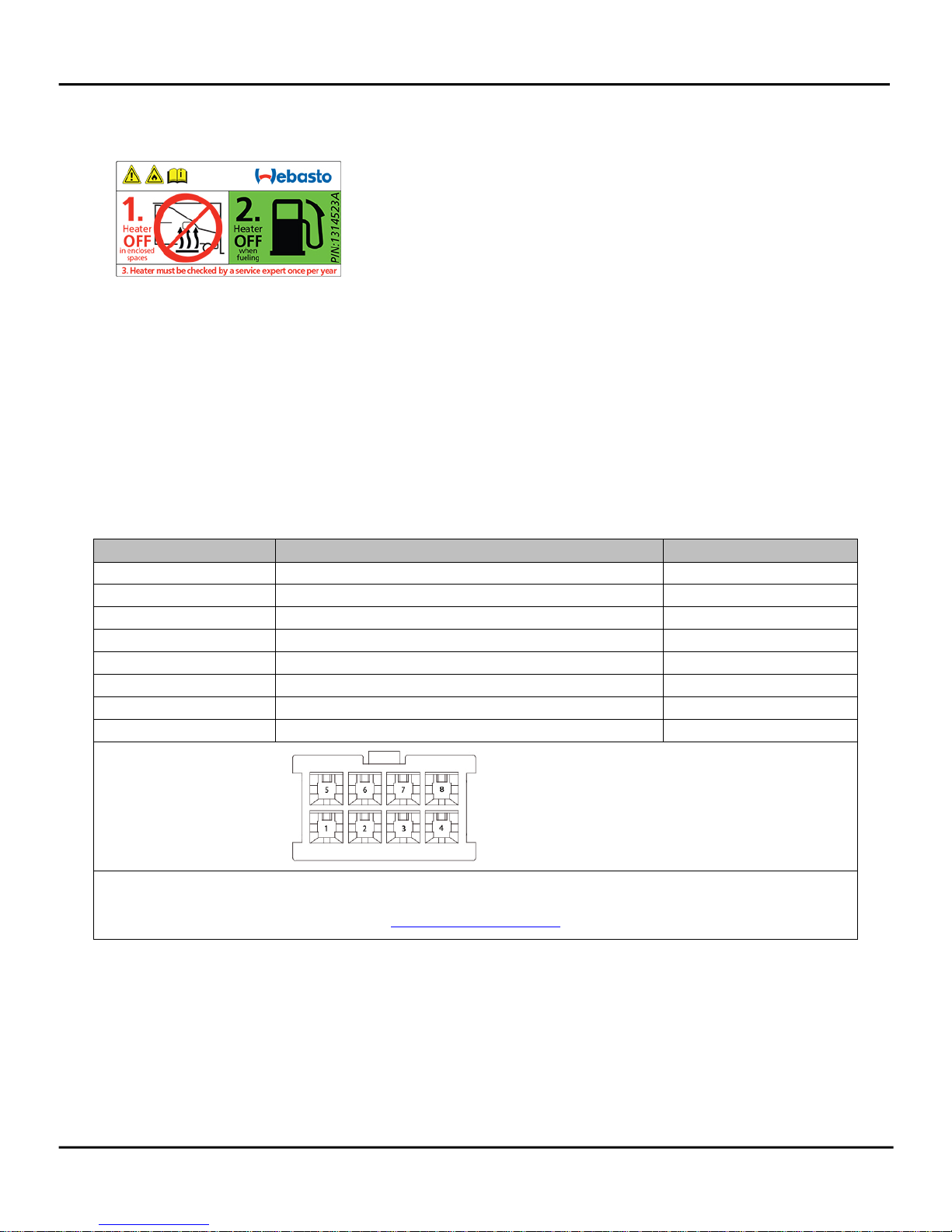
5. Apply the supplied “Heater Off” warning sticker in a highly visible location near the fuel filling
cap. Refer to the example sticker below.
6. Observe the operating section for proper menu setup.
Temperature Calibration
Based on the installation location of the SmarTemp Control, multiple factors such as door openings can
affect the SmarTemp Controls ambient temperature reading. If temperature offset adjustment is needed
see “Offset” on page 5 for further details.
Electrical Connections
This is a plug and play kit for an AT 2000 ST or AT 3900/5500 EVO Heater (refer to the compatibility
section for adaptor part numbers).
Connector Pin out
For terminal removal use: Molex terminal removal tool P/N: 11-03-0044
SIDE OF CONNECTOR
http://www.molex.com
2
Page 3
SmarTemp Control Installation - Operating Instructions
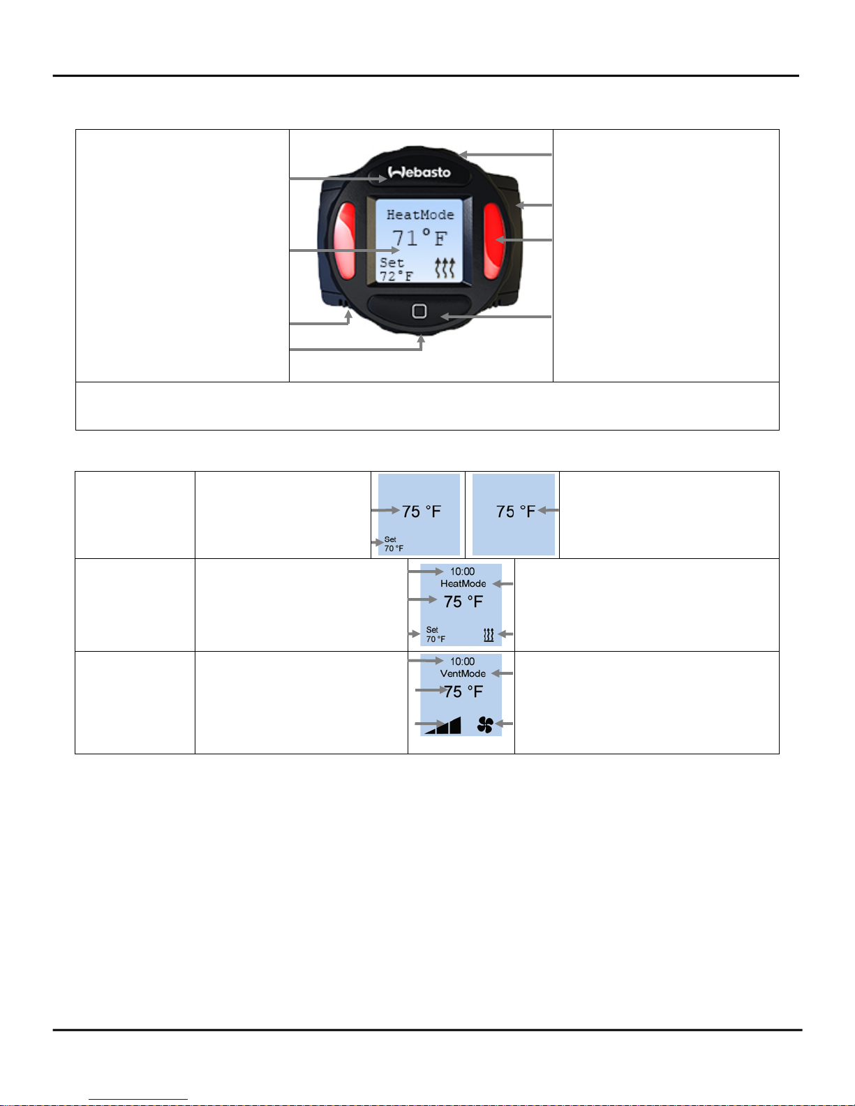
On / Off Button
Screw Cap
Status Indicator Light(s)
Selection Button
Mode Indicator
Mode Indicator
Component Description
Rotary Knob
LCD Screen
Ambient Temp Sensor
*Micro USB Service Port
* The micro USB Service Port is used for Webasto heater diagnostic purposes only. This adaptor
cannot be used to charge cell phones or other electronic devices.
LCD Screen Symbol Legend
Standby Mode
Standby Heater Mode
Ambient Temperature
User Set Temperature
Standby Vent Mode
Ambient Temperature
Timed Duration
Heat Mode
Ambient Temperature
User Set Temperature
Heat ON Indicator
Timed Duration
Vent Mode
Ambient Temperature
Fan Speed Indicator
(Low – Medium - High)
Vent ON Indicator
Operation
Using the rotary dial and the selection button (refer to component descriptions), navigation is made
simple. For example, to adjust your heaters set temperature to 70°F with a run time of 4 hours follow
these steps.
1. In HeatMode, use the rotary dial to adjust the set temperature to 70°F; Confirm the adjustment
by pushing the selection button.
2. Press the Selection button. Using the rotary dial, select: Options > Duration > Timed > Adjust
runtime to 4 hours. Confirm the adjustment by pushing the selection button.
Note: While in HeatMode the set temp can always be adjusted quickly by turning the rotary dial to the
desired temperature
3
Page 4
SmarTemp Control Installation - Operating Instructions
24 volt - Range between 21v – 25.5v
Definitions Default
Mode
Language
Temp Unit
Options
Duration
LVD
Mode changes the operation of the heater between heat
Heat Mode
mode and ventilation mode. Status indicator lights will
illuminate red for heat mode and blue for ventilation mode
when the selected mode is active.
Language changes between English, Spanish, and French. English
Temp Unit changes between Fahrenheit and Celsius units of
Fahrenheit
measure.
Advanced level adjustments; see below.
Duration allows for the selection of continuous heater
operation or timed operation (30 minutes – 14 hours).
Continuous
Note: If timed operation is selected 10 hours is default.
LVD “Low Voltage Disconnect” allows the user to adjust the
battery voltage level at which the Webasto SmarTemp Control
will shut down heater functionality.
If battery voltage is equal to or less than the threshold selected
+0.1v, the heater will not start. i.e. if an 11.5v threshold is
selected the heater cannot be started until B+ has reached
11.7v.
Password
PM Reminder
Error Codes
12 volt - Range between 11v – 12.5v
A password can be set to prevent access to the advanced
“Options” menu. Enter a 4 digit code passcode to begin
securing Options menu.
Note: This is typically used in fleet vehicle applications.
The product maintenance (PM) reminder will alert the operator
every 30 days with a message to run the heater for 20
minutes. The indicator lights will flash red as a visual reminder.
The operator will have the ability to Start the 20 minute
maintenance cycle or delay it via a “Snooze” option. When
Snooze is selected the PM reminder will postpone until
12:00PM the following day.
This section will log the last 5 error codes and the date that it
was set. Highlight and select an error code for a description.
Note: If the heater or the SmarTemp itself produces an error
code, the status indicator lights will flash red and the error will
display on the main screen. Error codes for the heater cannot
be reset through the Webasto SmarTemp Control. Refer to the
heater service manual for resetting an error code.
11.4v
24.2v
OFF
ON
No Errors
4
Page 5
SmarTemp Control Installation - Operating Instructions
Time & Date
Set time and date using the rotary knob and selection button.
12 hour
12 (AM / PM) or 24 hour available.
Offset
Depending on the installation location, the temperature
0°
reading may vary slightly. The Offset feature allows a
temperature adjustment of +/- 9°F (+/- 5°C). Adjust this as
necessary to obtain the most accurate ambient temperature
reading.
Default
Default allows the user to perform a factory reset of the
N/A
control settings.
NOTE: Heater information will NOT be affected.
SW Version
Back
This displays the firmware version of the Webasto SmarTemp
Control.
Installed
Version
Select this to return to the previous screen. N/A
Technical Information:
– Rated Voltage: 12 / 24V
– Operating Voltage Range: 12V: 11 – 16V | 24V: 21 - 32V
– Low Voltage Disconnect Range: 12V: 11 – 12.5V | 24V: 21 – 25.5V
– Operating Temperature: - 40° ... +185 °F (- 40° ... +85 °C)
– Set Temperature Range: 41° - 95° F (5° - 35° C)
– Installation Dimensions: (L x H x D) 2.7” x 2.2” x .60” (69.4mm x 55.5mm x 15.2mm)
Drilling Dimensions
Use the dimensions / template located in the back of this manual as a guide when installing and
mounting the Webasto SmarTemp Control.
NOTE: The Webasto SmarTemp Control has an integrated ambient temperature sensor. To ensure
this sensor properly measures the surrounding air, the control must be mounted vertical only.
5
Page 6
Commande SmarTemp
Interface à commande numérique pour
les réchauffeurs d’air EVO Air Top 2000 ST / 3900 / 5500
Installation / Consignes d’utilisation
Généralités
Nous vous remercions d’avoir choisi un appareil Webasto pour satisfaire à vos besoins de chauffage.
La commande Webasto SmarTemp vous permet d’utiliser rapidement et sans effort les réchauffeurs
d’air EVO AT 2000 ou AT 3900 / 5500.
Utilisation
La commande Webasto SmarTemp peut être exploitée au moyen d’un simple sélecteur rotatif
monté à l’extérieur de l’appareil sur l’un ou l’autre de ses côtés afin d’explorer les différentes
options du menu. Cliquez tout simplement sur le bouton de sélection ( ) pour faire votre choix.
Les sections de texte suivantes définissent chaque article du menu et la consigne par défaut.
Compatibilité
AT 2000 ST – adaptateur pour le faisceau de câbles (N/P : 5010612)
AT 3900 m/ 5500 EVO – adaptateur pour le faisceau de câbles (N/P : 5012138)
Mode d’assemblage
1. Déterminez l’endroit de fixation, de préférence sur une
surface plate et dans un endroit visible.
Remarque: Toujours installer dans une zone protégée
des effets de la météo et de la contamination.
2. Utilisez le forage dimensions / template à l'arrière de ce
manuel pour marquer légèrement les deux trous de
montage.
3. (Étape optionnelle) Pour acheminer le faisceau de
câbles à travers la surface de fixation, percez un trou de
Trou de 22mm comme notée sur la dimension forage /
template.
6
Page 7

Commande SmarTemp Installation – consignes d’utilisation
Remarque : Assurez-vous qu’il n’y a pas d’obstacles derrière l’emplacement de fixation
avant d’effectuer le perçage.
4. Fixez solidement la commande Webasto SmarTemp à l’aide des sept vis no 4.
5. Apposez l’autocollant de mise en garde signalant que le réchauffeur est à l’arrêt. Placez celui-
dans un endroit bien visible près du bouchon du réservoir de carburant. Vous référer à
l’autocollant de référence ci-contre.
6. Veuillez consulter la section traitant de l’utilisation de l’appareil pour une configuration
adéquate du menu.
Réglage de la température
Selon l’emplacement choisi pour l’installation de la commande SmarTemp, de nombreux facteurs dont la
fréquence d’ouverture des portières peuvent affecter la lecture de la température ambiante de la
commande SmarTemp. Si un réajustement de compensation de température est nécessaire, vous reporter
à la page six pour des informations complémentaires.
Raccordements électriques
Vous servir de la trousse de raccordement et de réglage qui convient aux réchauffeurs EVO AT 2000, AT
3900 / 5500. Voyez la section «compatibilité» pour connaître les numéros de pièce des adaptateurs.
7
Page 8

Commande SmarTemp Installation – consignes d’utilisation
No de la broche
Description
Couleur des fils
1
+12 / 24V
Rouge
2
Mise à la terre
Brun
3
Sortie du réchauffeur
Noir ou Gris
4
Code clignotant de diagnostic
Orange
Sortie analogique (point de réglage de la température
6
Sortie analogique (température ambiante)
Jaune
7
Entrée d’air de la ventilation
Mauve
8
Diagnostic d’entrée W-Bus
Vert
Écran ACL
Voyant d’état(s)
* Le microport de service USB sert uniquement au diagnostic du réchauffeur Webasto. Cet adaptateur
ne peut pas être utilisé aux fins d’appels téléphoniques ou autres appareils électroniques.
TERMINAL INSERT
Disposition des broches (électriques)
5
ambiante)
For terminal removal use: Molex terminal removal tool P/N: 11-03-0044
Description des composants
Bouton arrêt / marche
CÔTÉ DE CONNEXION
http://www.molex.com
Bleu
Poignée rotative
Bouton à vis
Bouton sélecteur
Capteur de température
ambiante
*Microport de service USB
8
Page 9

Commande SmarTemp Installation – consignes d’utilisation
l’utilisateur
Indicateur de mode
Indicateur de marche (ON) du
Légende des symboles de l’écran ACL
Mode secours
Mode chauffage
Mode ventilation
Mode secours du mode chauffage Mode secours de ventilation
Température
Température ambiante
ambiante
Réglage de
température
par
Temps d’utilisation
temporisé
Température ambiante
Indicateur de marche (ON) du
réchauffeur
Réglage de température
par l’utilisateur
Temps d’utilisation
temporisé
Indicateur de mode
Température ambiante
mode ventilation
Indicateur de vitesse du
ventilateur (basse –
moyenne – élevée)
Utilisation
À l’aide du sélecteur rotatif et du bouton de sélection (vous référer à la description des composants), la
navigation est fort simple. À titre d’exemple, ajustez le réglage du réchauffeur à 70° F et optez pour un
temps d’utilisation de 4 heures, en suivant pour ce faire les étapes suivantes.
1. Au mode chauffage, utilisez le sélecteur rotatif pour régler la température à 70° F et validez ce
réglage en appuyant sur le bouton de sélection.
2. Appuyez sur le bouton sélection ; utilisez le sélecteur rotatif et sélectionnez : opérations >
durée de temporisation > temporisation > réglage du temps d’utilisation jusqu’à 4 heures.
Validez ce réglage en appuyant sur le bouton de sélection.
Remarque : Au mode chauffage, le réglage de température peut être modifié rapidement en
tournant le sélecteur rotatif vers la valeur de température désirée.
9
Page 10

Commande SmarTemp Installation – consignes d’utilisation
Définitions
Par défaut
Mode
Le mode opérationnel modifie l’exploitation du réchauffeur en
Mode
Langues
Textes en langues anglaise, française et espagnole.
Anglais
Degrés de
Les degrés de température sont exprimés en valeurs
Fahrenheit
Options
Réglages de niveau perfectionnés.
Durée
La fonction de durée permet de choisir entre un
Continu
LVD
Le débranchement en basse tension (LVD) permet à
Mot de passe
Un mot de passe peut être mis en fonction pour bloquer
OFF (position
température
opérationnelle
passant du mode chauffage au mode ventilation. Voyant
d'état s'allume en rouge pour le mode thermique et bleu pour
le mode de ventilation lorsque le mode sélectionné est actif.
Fahrenheit et Celsius.
fonctionnement continu et un fonctionnement temporisé de
30 minutes à 14 heures. Remarque : Si le fonctionnement
temporisé est sélectionné, la durée par défaut est de 10
heures.
l’utilisateur de régler la tension de la batterie au niveau duquel
la commande SmarTemp Webasto arrête le fonctionnement
du réchauffeur.
chauffage
Si la tension de la batterie est égale ou inférieure au seuil
sélectionné de ± 0,1 V, le réchauffeur ne démarre pas. Par
exemple, si le seuil sélectionné est de 11,5 V, le réchauffeur ne
peut pas se mettre en marche avant que B+ n’ait atteint 11,7
V.
12 volts – plage de 11 V à 12,5 V
24 volts – plage de 21 V à 25,5 V
l’accès au menu perfectionné «Options». Introduisez un code
de quatre chiffres pour sécuriser le menu «Options».
Remarque. Cette précaution est surtout souhaitable dans le
cas des parcs de véhicules.
11,4 V
24,2 V
arrêt)
10
Page 11

Commande SmarTemp Installation – consignes d’utilisation
Définitions
Par défaut
Fonction de rappel
La fonction de rappel PM (entretien du produit) émet un
message d’alerte tous les trente jours pour rappeler à
minutes. Des voyants de signalisation de couleur rouge
L’utilisateur peut soit actionner immédiatement le cycle
option est sollicitée, la fonction de rappel PM retarde
ON
Codes d’erreurs
Cette fonction enregistre chronologiquement les cinq derniers codes
Aucune
Heure et date
Réglez l’heure et la date en vous servant du sélecteur rotatif et
12 h
Rajustement de
Dépendamment de l’emplacement de l’installation, la lecture
0
0
Fonction par
La fonction par défaut permet à l’utilisateur d’effectuer un
S/O
Version SW
Cette fonction affiche la version de la microprogrammation de
Version
Retour en
Sélectionnez cette fonction pour retourner à l’écran précédent.
S/O
PM
l’utilisateur de faire fonctionner le réchauffeur pendant 20
clignotent pour confirmer ce rappel.
d’entretien de 20 minutes, soit le différer au moyen de
l’option d’arrêt momentané «Snooze». Quand cette dernière
l’opération jusqu’à 12 h le lendemain.
d'erreur, y compris la date de sélection. Mettez en surbrillance et
sélectionner un code d'erreur pour une description.
Remarque: Si le chauffage ou la SmarTemp lui-même émet un code
d'erreur, le voyant clignote en rouge et le type d'erreur est affiché
sur l'écran principal. Les codes d'erreur de l'appareil ne peuvent pas
être restaurés à l'aide de la commande SmarTemp Webasto.
Reportez-vous au manuel d'entretien pour rétablir le code d'erreur.
(position
marche)
erreur
du bouton de sélection. Plages disponibles : de midi à minuit
et 24 h.
la température
défaut
de la température peut varier légèrement. La fonction de
rajustement permet des ajustements de température de +/- 9
0
(+/- 5
C). Réglez cette fonction de manière à obtenir la lecture
la plus précise de la température ambiante.
réajustement des consignes de réglage installées en usine.
arrière
la commande Webasto SmarTemp
11
0
F
installée
Page 12

Commande SmarTemp Installation – consignes d’utilisation
Informations techniques
- Tension nominale : 12 / 24 v
- Tension de fonctionnement : 12V: 11 – 16V | 24V: 21 - 32V
- Low Voltage Disconnect Plage: 12 V : 11 – 12,5 V | 24 V : 21 – 25,5 V
- Température d’utilisation : -40
o
… + 185
o F
(-40o … +185o C)
- Définir la plage de température: 41° - 95° F (5° - 35° C)
- Dimensions de l’installation (L x H x P) 2,7 po x 2,2 po x 0,60 po (69,4 mm x 55,5 mm x 15,2
mm)
Dimensions de perçage
Utilisez les dimensions / template situés à l'arrière du manuel comme un guide lors de l'installation
et le montage de la Webasto SmarTemp contrôle.
Remarque : La commande Webasto SmarTemp est dotée d’un capteur de température ambiante.
Pour que le capteur mesure correctement l’air environnant, il doit être absolument installé à la
verticale.
12
Page 13

Nota:
(Paso opcional)
Nota:
Controlador SmarTemp
Interfaz de control digital para calentadores
de aire superior 2000 ST / 3900/5500 EVO
Instrucciones de instalación / operación
General
Gracias por elegir Webasto para satisfacer sus necesidades de calefacción. El controlador Webasto
SmarTemp le permite operar de forma rápida y simple los calentadores de aire AT 2000 ST o AT 3900 /
5500 EVO.
Operando
El controlador Webasto SmarTemp puede ser operado utilizando un simple mando giratorio alrededor
del exterior de la unidad para navegar a través de las diferentes opciones del menú. Simplemente haga
clic en el botón ( ) para hacer su elección. Las siguientes secciones definirán cada elemento del menú y
su valor predeterminado.
Compatibilidad
AT 2000 ST – Adaptador de arnés (P/N: 5010612)
AT 3900 / 5500 EVO – Adaptador de arnés (P/N: 5012138)
Procedimiento de montaje
1. Encontrar una ubicación de montaje adecuada (si es posible,
en una superficie plana) en un área visible.
Siempre instale en un área protegida de los
efectos del clima y la contaminación.
2. Utilice la dimensiones de perforación / plantilla en la
parte de atrás de este manual para marcar ligeramente
los dos orificios de montaje.
3.
a través de la superficie de montaje, perfore un agujero
de 22 mm como se indica en la dimensión de taladro /
plantilla.
perforación de que no haya obstáculos detrás de la posición de montaje.
4. Asegure el Controlador Webasto SmarTemp usando los dos tornillos #4 suministrados.
Asegúrese siempre antes de realizar la
Para el recorrido del manojo de cables
13
Page 14

SmarTemp Control Instalación - Instrucciones de funcionamiento
Número de Pin
Descripción
Color del cable
1
+12 / 24V
Rojo
2
GND
Marrón
3
Salida del calentador
Negro o Gris
4
Código de diagnóstico del parpadeo
Naranja
5
Salida analógica (Punto de ajuste de
temperatura)
Azul
6
Salida analógica (Temperatura ambiente)
Amarillo
7
Entrada del respiradero
Púrpura
8
Entrada de diagnóstico W-Bus
Verde
TERMINAL INSERT
LADO DE CONECTOR
5. Aplique la etiqueta de advertencia “Calentador apagado” suministrada en un lugar muy visible
cerca de la tapa de llenado de combustible. Consulte el ejemplo de la siguiente etiqueta.
6. Observe la sección operando para una configuración apropiada del menú.
Calibración de la temperatura
Basado en la ubicación de la instalación del controlador SmarTemp, múltiples factores tales como la
apertura de puertas pueden afectar la lectura de la temperatura ambiente de los Controladores
SmarTemp. Si se requiere un ajuste de temperatura compensada consulte “Offset” en la página 5 para
obtener más detalles.
Conexiones eléctricas
Este es un kit conecte y use para un calentador AT 2000 ST o AT 3900/5500 EVO (consulte la sección de
compatibilidad para los números de referencia de los adaptadores).
Asignación de los conectores
Para remover el terminal Molex usar herramienta P/N: 11-03-0044
http://www.molex.com
14
Page 15

SmarTemp Control Instalación - Instrucciones de funcionamiento
Botón de
encendido/apagado
Pantalla LCD
Luz que indica el estado(s)
Sensor de temperatura
USB
Botón de selección
* El micro puerto de servicio USB es utilizado solamente con fines de diagnostico del calentador
dispositivos electrónicos.
el usuario
Duración programada
por el usuario
Indicador del modo
Indicador del modo
Descripción del componente
Mando giratorio
Protector de los tornillos
ambiente
*Micro puerto de servicio
Webasto. Este adaptador no puede ser usado para recargar teléfonos celulares u otros
Leyenda de los símbolos de la pantalla LCD
Modo calefacción en
espera
Temperatura
Modo en
espera
Modo
ambiente
Temperatura
definida por
Temperatura ambiente
calefacción
Temperatura definida
Indicador de calefacción
encendida
Duración programada
Modo
ventilación
Temperatura ambiente
Indicador de la
Indicador de ventilación encendida
velocidad del
ventilador (Baja –
Media - Alta)
Modo ventilación en espera
Temperatura ambiente
15
Page 16

SmarTemp Control Instalación - Instrucciones de funcionamiento
24 volt - Rango entre 21v – 25.5v
Operando
Usando el mando giratorio y el botón de selección (consulte la descripción del componente), la
navegación es simple. Por ejemplo, para ajustar la temperatura del calentador a 70°F con una duración
de 4 horas, siga estos pasos.
3. En modo calefacción, use el mando giratorio para ajustar la temperatura a 70°F; Confirme su
elección presionando el botón de selección.
4. Pulse el botón de selección. Usando el mando giratorio, seleccione: Opciones > Duración >
Programada> Ajuste la duración en 4 horas. Confirme su elección presionando el botón de
selección.
5. Nota: Mientras se encuentre en modo calefacción el ajuste de la temperatura se puede realizar
rápidamente girando el mando a la temperatura deseada
Modo
Definiciones Por defecto
Modo varía el funcionamiento del calentador entre
modo calefacción y modo ventilación. Status LED
indicador se ilumina en rojo para el modo calor y el
azul para el modo de ventilación cuando el modo
seleccionado es activo.
Modo
calefacción
Idioma
Unidad de temperatura
Opciones
Duración
DBT
Idioma varía entre inglés, español, y francés. Inglés
Unidad temperatura varía entre las unidades de
medición Fahrenheit y Celsius.
Ajustes de nivel avanzado; vea debajo.
Duración permite la selección de operaciones
continuas del calentador o funcionamiento
temporizado (30 minutos – 14 horas).
Nota: Si se selecciona funcionamiento temporizado el
tiempo por defecto son 10 horas.
Fahrenheit
Continua
DBT “Desconexión por baja tensión” permite al
usuario ajustar el nivel de voltaje de la batería en
el cual el controlador Webasto SmarTemp
apagará la funcionalidad del calentador.
Si el voltaje de la batería es igual o menor que el
umbral seleccionado +0.1v, el calentador no
arrancará. Por ejemplo: si un umbral de 11.5v es
seleccionado el calentador no puede ser iniciado
hasta que B+ haya alcanzado 11.7v.
12 volt - Rango entre 11v – 12.5v
11.4v
24.2v
16
Page 17

SmarTemp Control Instalación - Instrucciones de funcionamiento
Definiciones Por defecto
Contraseña
Recordatorio
de MP
Códigos de
error
Una contraseña puede ser configurada para prevenir el
acceso al menú de “Opciones” avanzadas. Introduzca una
clave de 4 dígitos para empezar a asegurar el menú
Opciones.
Nota: Esto se usa típicamente en aplicaciones de vehículos
de la flota.
El recordatorio del mantenimiento del producto (MP) alertará
al operador cada 30 días con un mensaje para ejecutar el
calentador durante 20 minutos. Las luces indicadoras
parpadearán en rojo como un recordatorio visual.
El operador tendrá la posibilidad de iniciar el ciclo de
mantenimiento o de retrasarlo a través de la opción ‘’Más
tarde’’. Cuando se seleccione la opción más tarde el
recordatorio de MP se pospondrá hasta las 12:00 PM del
siguiente día.
En esta sección se registrarán los últimos 5 códigos de error y
la fecha en que se produjeron. Remarque y seleccione un
código de error para obtener una descripción.
NOTA: Si el calentador o el propio SmarTemp producir un
código de error, las luces indicadoras parpadeará en color
rojo y se muestra el error en la pantalla principal. Los códigos
de error de la calefacción no se pueden restablecer a través
del controlador Webasto SmarTemp. Consulte el manual
para el calentador para restablecer un código de error.
APAGADO
ENCENDIDO
Sin errores
Hora y fecha
Offset
Por defecto
Versión de
SW
Atrás
Ajuste la hora y la fecha con el mando giratorio y el botón de
12 horas
selección. Modos de 12 (AM/PM) o 24 horas disponibles.
Dependiendo de la ubicación de la instalación, la lectura de la
0°
temperatura puede variar ligeramente. La función Offset
permite un ajuste de la temperatura de +/- 9°F (+/- 5°C).
Ajuste esto tanto como sea necesario para obtener una
lectura de la temperatura ambiente más exacta.
Por defecto permite al usuario llevar a cabo una restauración
N/A
de los parámetros de control a valores de fábrica.
NOTA: La información del calentador no se verá afectada.
Esto muestra la versión del firmware del Controlador
Webasto SmarTemp.
Versión
instalada
Seleccione esta opción para volver a la pantalla anterior. N/A
17
Page 18

SmarTemp Control Instalación - Instrucciones de funcionamiento
Información técnica:
– Tensión normal: 12 / 24V
– Rango de voltaje de operación: 12V: 11 – 16V | 24V: 21 - 32V
– Rango de voltaje: 12V: 11 – 12.5V | 24V: 21 – 25.5V
– Temperatura de funcionamiento: - 40° ... +185 °F (- 40° ... +85 °C)
– Ajuste Rango de temperatura: 41° - 95° F (5° - 35° C)
– Dimensiones de la instalación: (L x H x D) 2.7” x 2.2” x .60” (69.4mm x 55.5mm x 15.2mm)
Dimensiones de perforación
Utilice las dimensiones / plantilla ubicada en la parte posterior del manual como guía durante la
instalación y el montaje de la Webasto SmarTemp control.
NOTA: El Controlador Webasto SmarTemp Control tiene un sensor de temperatura ambiente
integrado. Para asegurarse de que el sensor mide adecuadamente el aire circundante, el control sólo
puede ser montado de forma vertical.
18
Page 19

Use 5/64 Drill Bit
Usar 5/64 boquilla
TOP
Utilisez une meche de 5/64
HAUT
SUPERIOR
Page 20

Webasto Thermo & Comfort N.A., Inc.
Fenton, MI 48430 USA
Phone:
810-593-6000
http://www.techwebasto.com
Org. 5/2013 Rev. 10/2016 Ver. 1.8 P/N: 5010621A
15083 North Road
Fax:
Email:
Internet:
810-593-6001
info-us@webasto.com
http://www.webasto.us
 Loading...