

Page 1

Luft-Heizgeräte
Air Heaters
03/2003
Workshop Manual
Air Top 2000 STC
Trade names:
Air Top 2000 STC B (petrol)
Air Top 2000 STC D (diesel)
Page 2

Improper installation or repair of Webasto heating and cooling systems can cause fire or the
leakage of deadly carbon monoxide leading to serious injury or death.
To install and repair Webasto heating and cooling systems you need to have completed a
Webasto training course and have the appropriate technical documentation, special tools
and special equipment.
Only genuine Webasto parts may be used. See also Webasto air and water heaters
accessories catalogue.
NEVER try to install or repair Webasto heating or cooling systems if you have not completed
a Webasto training course, you do not have the necessary technical skills and you do not
have the technical documentation, tools and equipment available to ensure that you can
complete the installation and repair work properly.
ALWAYS carefully follow Webasto installation and repair instructions and heed all
WARNINGS.
Webasto rejects any liability for problems and damage caused by the system being installed
by untrained personnel.
Page 3

Air Top 2000 STC Table of Contents
Table of Contents
1 Introduction . . . . . . . . . . . . . . . . . . . . . . . . . . . . . . . . . . . . . . . . . . . . . . . . . . . . . . . . . . . . . . . . . . . . . . 101
1.1 Contents and purpose . . . . . . . . . . . . . . . . . . . . . . . . . . . . . . . . . . . . . . . . . . . . . . . . . . . . . . . . . . . . . . . . .101
1.1.1 Use of air heaters . . . . . . . . . . . . . . . . . . . . . . . . . . . . . . . . . . . . . . . . . . . . . . . . . . . . . . . . . . . . . . 101
1.2 Meaning of signal words . . . . . . . . . . . . . . . . . . . . . . . . . . . . . . . . . . . . . . . . . . . . . . . . . . . . . . . . . . . . . . . 101
1.2.1 General safety information . . . . . . . . . . . . . . . . . . . . . . . . . . . . . . . . . . . . . . . . . . . . . . . . . . . . . . .101
2 General description . . . . . . . . . . . . . . . . . . . . . . . . . . . . . . . . . . . . . . . . . . . . . . . . . . . . . . . . . . . . . . . . 201
2.1 Drive unit . . . . . . . . . . . . . . . . . . . . . . . . . . . . . . . . . . . . . . . . . . . . . . . . . . . . . . . . . . . . . . . . . . . . . . . . . . .201
2.2 Heat exchanger . . . . . . . . . . . . . . . . . . . . . . . . . . . . . . . . . . . . . . . . . . . . . . . . . . . . . . . . . . . . . . . . . . . . . . 202
2.3 Burner with combustion chamber . . . . . . . . . . . . . . . . . . . . . . . . . . . . . . . . . . . . . . . . . . . . . . . . . . . . . . . .202
2.4 Control unit . . . . . . . . . . . . . . . . . . . . . . . . . . . . . . . . . . . . . . . . . . . . . . . . . . . . . . . . . . . . . . . . . . . . . . . . .202
2.5 Flame monitor (petrol heater only) . . . . . . . . . . . . . . . . . . . . . . . . . . . . . . . . . . . . . . . . . . . . . . . . . . . . . . . . 202
2.6 Glow plug . . . . . . . . . . . . . . . . . . . . . . . . . . . . . . . . . . . . . . . . . . . . . . . . . . . . . . . . . . . . . . . . . . . . . . . . . . 203
2.7 Overheating sensor . . . . . . . . . . . . . . . . . . . . . . . . . . . . . . . . . . . . . . . . . . . . . . . . . . . . . . . . . . . . . . . . . . . 203
2.8 Fuel pump . . . . . . . . . . . . . . . . . . . . . . . . . . . . . . . . . . . . . . . . . . . . . . . . . . . . . . . . . . . . . . . . . . . . . . . . . . 203
3 Functional description . . . . . . . . . . . . . . . . . . . . . . . . . . . . . . . . . . . . . . . . . . . . . . . . . . . . . . . . . . . . . . 301
3.1 Control element . . . . . . . . . . . . . . . . . . . . . . . . . . . . . . . . . . . . . . . . . . . . . . . . . . . . . . . . . . . . . . . . . . . . . . 301
3.2 Switching on . . . . . . . . . . . . . . . . . . . . . . . . . . . . . . . . . . . . . . . . . . . . . . . . . . . . . . . . . . . . . . . . . . . . . . . .301
3.3 Heating mode . . . . . . . . . . . . . . . . . . . . . . . . . . . . . . . . . . . . . . . . . . . . . . . . . . . . . . . . . . . . . . . . . . . . . . .301
3.4 Control mode . . . . . . . . . . . . . . . . . . . . . . . . . . . . . . . . . . . . . . . . . . . . . . . . . . . . . . . . . . . . . . . . . . . . . . . 301
3.5 Control pause . . . . . . . . . . . . . . . . . . . . . . . . . . . . . . . . . . . . . . . . . . . . . . . . . . . . . . . . . . . . . . . . . . . . . . . 301
3.6 Switching off . . . . . . . . . . . . . . . . . . . . . . . . . . . . . . . . . . . . . . . . . . . . . . . . . . . . . . . . . . . . . . . . . . . . . . . .302
3.7 Heater functions in ADR vehicles . . . . . . . . . . . . . . . . . . . . . . . . . . . . . . . . . . . . . . . . . . . . . . . . . . . . . . . . . 302
3.8 Fault switch-off . . . . . . . . . . . . . . . . . . . . . . . . . . . . . . . . . . . . . . . . . . . . . . . . . . . . . . . . . . . . . . . . . . . . . . 302
3.8.1 Fault monitoring . . . . . . . . . . . . . . . . . . . . . . . . . . . . . . . . . . . . . . . . . . . . . . . . . . . . . . . . . . . . . . .303
3.8.2 Resetting fault switch-off . . . . . . . . . . . . . . . . . . . . . . . . . . . . . . . . . . . . . . . . . . . . . . . . . . . . . . .303
4 Technical data . . . . . . . . . . . . . . . . . . . . . . . . . . . . . . . . . . . . . . . . . . . . . . . . . . . . . . . . . . . . . . . . . . . . 401
4.1 General technical data . . . . . . . . . . . . . . . . . . . . . . . . . . . . . . . . . . . . . . . . . . . . . . . . . . . . . . . . . . . . . . . . . 401
4.1 Setpoints . . . . . . . . . . . . . . . . . . . . . . . . . . . . . . . . . . . . . . . . . . . . . . . . . . . . . . . . . . . . . . . . . . . . . . . . . . . 402
5 Troubleshooting. . . . . . . . . . . . . . . . . . . . . . . . . . . . . . . . . . . . . . . . . . . . . . . . . . . . . . . . . . . . . . . . . . . 501
5.1 General information . . . . . . . . . . . . . . . . . . . . . . . . . . . . . . . . . . . . . . . . . . . . . . . . . . . . . . . . . . . . . . . . . . . 501
5.2 General fault symptoms . . . . . . . . . . . . . . . . . . . . . . . . . . . . . . . . . . . . . . . . . . . . . . . . . . . . . . . . . . . . . . . .501
5.3 Fault symptoms during operation. . . . . . . . . . . . . . . . . . . . . . . . . . . . . . . . . . . . . . . . . . . . . . . . . . . . . . . . .502
5.4 Fault code output (hexadecimal / Webasto Thermo Test) . . . . . . . . . . . . . . . . . . . . . . . . . . . . . . . . . . . . . . . 503
5.5 Fault code output (flashing or FXX output). . . . . . . . . . . . . . . . . . . . . . . . . . . . . . . . . . . . . . . . . . . . . . . . . .506
6 Function checks . . . . . . . . . . . . . . . . . . . . . . . . . . . . . . . . . . . . . . . . . . . . . . . . . . . . . . . . . . . . . . . . . . . 601
6.1 General information . . . . . . . . . . . . . . . . . . . . . . . . . . . . . . . . . . . . . . . . . . . . . . . . . . . . . . . . . . . . . . . . . . . 601
6.2 Required test and measuring equipment . . . . . . . . . . . . . . . . . . . . . . . . . . . . . . . . . . . . . . . . . . . . . . . . . . . 601
6.3 Settings . . . . . . . . . . . . . . . . . . . . . . . . . . . . . . . . . . . . . . . . . . . . . . . . . . . . . . . . . . . . . . . . . . . . . . . . . . . . 603
6.3.1 Setting the CO2 content . . . . . . . . . . . . . . . . . . . . . . . . . . . . . . . . . . . . . . . . . . . . . . . . . . . . . . . . .603
6.3.2 CO2 setting for reference heater . . . . . . . . . . . . . . . . . . . . . . . . . . . . . . . . . . . . . . . . . . . . . . . . . . . 603
6.4 Testing individual components . . . . . . . . . . . . . . . . . . . . . . . . . . . . . . . . . . . . . . . . . . . . . . . . . . . . . . . . . . . 604
I
Page 4

Table of Contents Air Top 2000 STC
6.4.1 Component: burner . . . . . . . . . . . . . . . . . . . . . . . . . . . . . . . . . . . . . . . . . . . . . . . . . . . . . . . . . . . . 605
6.4.2 Testing resistance of flame monitor (petrol heater only) . . . . . . . . . . . . . . . . . . . . . . . . . . . . . . . . . 606
6.4.3 Component: glow plug . . . . . . . . . . . . . . . . . . . . . . . . . . . . . . . . . . . . . . . . . . . . . . . . . . . . . . . . . . 608
6.4.4 Component: drive unit . . . . . . . . . . . . . . . . . . . . . . . . . . . . . . . . . . . . . . . . . . . . . . . . . . . . . . . . . . 610
6.4.5 Component: overheating temperature sensor . . . . . . . . . . . . . . . . . . . . . . . . . . . . . . . . . . . . . . . . . 611
6.4.6 Component: control unit . . . . . . . . . . . . . . . . . . . . . . . . . . . . . . . . . . . . . . . . . . . . . . . . . . . . . . . . 612
6.4.7 Component: heater . . . . . . . . . . . . . . . . . . . . . . . . . . . . . . . . . . . . . . . . . . . . . . . . . . . . . . . . . 613
7 Wiring diagrams . . . . . . . . . . . . . . . . . . . . . . . . . . . . . . . . . . . . . . . . . . . . . . . . . . . . . . . . . . . . . . . . . . . 701
7.1 General information . . . . . . . . . . . . . . . . . . . . . . . . . . . . . . . . . . . . . . . . . . . . . . . . . . . . . . . . . . . . . . . . . . 701
7.2 System wiring diagrams . . . . . . . . . . . . . . . . . . . . . . . . . . . . . . . . . . . . . . . . . . . . . . . . . . . . . . . . . . . . . . . 702
7.3 Legends to system wiring diagrams . . . . . . . . . . . . . . . . . . . . . . . . . . . . . . . . . . . . . . . . . . . . . . . . . . . . . 704
7.4 Pin assignments plug connection X6, 18-pin . . . . . . . . . . . . . . . . . . . . . . . . . . . . . . . . . . . . . . . . . . . . . . . . 705
8 Servicing . . . . . . . . . . . . . . . . . . . . . . . . . . . . . . . . . . . . . . . . . . . . . . . . . . . . . . . . . . . . . . . . . . . . . . . . . 801
8.1 General information . . . . . . . . . . . . . . . . . . . . . . . . . . . . . . . . . . . . . . . . . . . . . . . . . . . . . . . . . . . . . . . . . . 801
8.2 Working on the heater . . . . . . . . . . . . . . . . . . . . . . . . . . . . . . . . . . . . . . . . . . . . . . . . . . . . . . . . . . . . . . . . 801
8.3 Working on the vehicle . . . . . . . . . . . . . . . . . . . . . . . . . . . . . . . . . . . . . . . . . . . . . . . . . . . . . . . . . . . . . . . . 801
8.4 Heater test run . . . . . . . . . . . . . . . . . . . . . . . . . . . . . . . . . . . . . . . . . . . . . . . . . . . . . . . . . . . . . . . . . . . . . . 801
8.5 Servicing . . . . . . . . . . . . . . . . . . . . . . . . . . . . . . . . . . . . . . . . . . . . . . . . . . . . . . . . . . . . . . . . . . . . . . . . . . . 801
8.6 Visual inspection and installation requirements . . . . . . . . . . . . . . . . . . . . . . . . . . . . . . . . . . . . . . . . . . . . . . 801
8.6.1 Heating air system . . . . . . . . . . . . . . . . . . . . . . . . . . . . . . . . . . . . . . . . . . . . . . . . . . . . . . . . . . . . . 801
8.6.2 Fuel supply . . . . . . . . . . . . . . . . . . . . . . . . . . . . . . . . . . . . . . . . . . . . . . . . . . . . . . . . . . . . . . . . . . . 802
8.6.2.1 Fuel take-off, general . . . . . . . . . . . . . . . . . . . . . . . . . . . . . . . . . . . . . . . . . . . . . . . 802
8.6.2.2 Permissible fuel pressure fuel line lengths. . . . . . . . . . . . . . . . . . . . . . . . . . . . . . . . 802
8.6.2.3 Fuel take-off via tank drain plug (from plastic or metal fuel tank) . . . . . . . . . . . . . . 803
8.6.2.4 Webasto tank extracting device for plastic fuel tank . . . . . . . . . . . . . . . . . . . . . . . . 803
8.6.2.5 Webasto tank extracting device for metal tank . . . . . . . . . . . . . . . . . . . . . . . . . . . . 803
8.6.2.6 Fuel lines . . . . . . . . . . . . . . . . . . . . . . . . . . . . . . . . . . . . . . . . . . . . . . . . . . . . . . . . 803
8.6.2.7 Connecting 2 fuel lines with a hose . . . . . . . . . . . . . . . . . . . . . . . . . . . . . . . . . . . . 804
8.6.3 Fuel pump . . . . . . . . . . . . . . . . . . . . . . . . . . . . . . . . . . . . . . . . . . . . . . . . . . . . . . . . . . . . . . . . . . . 804
8.6.3.1 Installation location . . . . . . . . . . . . . . . . . . . . . . . . . . . . . . . . . . . . . . . . . . . . . . . . 804
8.6.3.2 Installation and attachment . . . . . . . . . . . . . . . . . . . . . . . . . . . . . . . . . . . . . . . . . . 804
8.6.4 Fuel filter . . . . . . . . . . . . . . . . . . . . . . . . . . . . . . . . . . . . . . . . . . . . . . . . . . . . . . . . . . . . . . . . . . . . 805
8.6.5 Combustion air supply . . . . . . . . . . . . . . . . . . . . . . . . . . . . . . . . . . . . . . . . . . . . . . . . . . . . . . . . . . 805
8.6.6 Exhaust line . . . . . . . . . . . . . . . . . . . . . . . . . . . . . . . . . . . . . . . . . . . . . . . . . . . . . . . . . . . . . . . . . . 805
8.6.7 Exhaust silencer . . . . . . . . . . . . . . . . . . . . . . . . . . . . . . . . . . . . . . . . . . . . . . . . . . . . . . . . . . . . . . . 805
8.6.8 Combustion air intake and exhaust pipes . . . . . . . . . . . . . . . . . . . . . . . . . . . . . . . . . . . . . . . . . . . . 806
8.6.9 Electrical Connections . . . . . . . . . . . . . . . . . . . . . . . . . . . . . . . . . . . . . . . . . . . . . . . . . . . . . . . . . . . 806
8.6.9.1 Heater and control element connection . . . . . . . . . . . . . . . . . . . . . . . . . . . . . . . . . 806
8.6.9.2 Supply voltage connection . . . . . . . . . . . . . . . . . . . . . . . . . . . . . . . . . . . . . . . . . . . 806
8.6.9.3 Control element connection . . . . . . . . . . . . . . . . . . . . . . . . . . . . . . . . . . . . . . . . . . 807
8.7 Removing and installing . . . . . . . . . . . . . . . . . . . . . . . . . . . . . . . . . . . . . . . . . . . . . . . . . . . . . . . . . . . . . . . 809
8.7.1 Removing and installing heater . . . . . . . . . . . . . . . . . . . . . . . . . . . . . . . . . . . . . . . . . . . . . . . . . . . . 809
8.7.1.1 Removal . . . . . . . . . . . . . . . . . . . . . . . . . . . . . . . . . . . . . . . . . . . . . . . . . . . . . . . . . 809
8.7.1.2 Installation . . . . . . . . . . . . . . . . . . . . . . . . . . . . . . . . . . . . . . . . . . . . . . . . . . . . . . . 809
8.8 Commissioning . . . . . . . . . . . . . . . . . . . . . . . . . . . . . . . . . . . . . . . . . . . . . . . . . . . . . . . . . . . . . . . . . . . . . . 809
II
Page 5

Air Top 2000 STC Table of Contents
9 Repair . . . . . . . . . . . . . . . . . . . . . . . . . . . . . . . . . . . . . . . . . . . . . . . . . . . . . . . . . . . . . . . . . . . . . . . . . . 901
9.1 General information . . . . . . . . . . . . . . . . . . . . . . . . . . . . . . . . . . . . . . . . . . . . . . . . . . . . . . . . . . . . . . . . . . . 901
9.1.1 Work on stripped down components . . . . . . . . . . . . . . . . . . . . . . . . . . . . . . . . . . . . . . . . . . . . . . . 901
9.1.1.1 Cleaning . . . . . . . . . . . . . . . . . . . . . . . . . . . . . . . . . . . . . . . . . . . . . . . . . . . . . . . . . 901
9.1.1.2 Visual inspection . . . . . . . . . . . . . . . . . . . . . . . . . . . . . . . . . . . . . . . . . . . . . . . . . . . 901
9.1.2 Carrying out modifications . . . . . . . . . . . . . . . . . . . . . . . . . . . . . . . . . . . . . . . . . . . . . . . . . . . . . . .901
9.1.2.1 Installing of an external room temperature sensor. . . . . . . . . . . . . . . . . . . . . . . . . .901
9.2 Dismantling and assembling. . . . . . . . . . . . . . . . . . . . . . . . . . . . . . . . . . . . . . . . . . . . . . . . . . . . . . . . . . . . . 902
9.2.1 Removing casing parts. . . . . . . . . . . . . . . . . . . . . . . . . . . . . . . . . . . . . . . . . . . . . . . . . . . . . . . . . . . 902
9.2.1.1 Cover for electrical connection . . . . . . . . . . . . . . . . . . . . . . . . . . . . . . . . . . . . . . . .902
9.2.1.2 Grille for heating air inlet and outlet . . . . . . . . . . . . . . . . . . . . . . . . . . . . . . . . . . . . 902
9.2.1.3 Cover for heating air inlet and outlet . . . . . . . . . . . . . . . . . . . . . . . . . . . . . . . . . . . .902
9.2.1.4 Upper casing . . . . . . . . . . . . . . . . . . . . . . . . . . . . . . . . . . . . . . . . . . . . . . . . . . . . . . 902
9.2.1.5 Lower casing . . . . . . . . . . . . . . . . . . . . . . . . . . . . . . . . . . . . . . . . . . . . . . . . . . . . . . 902
9.2.2 Fitting the casing parts . . . . . . . . . . . . . . . . . . . . . . . . . . . . . . . . . . . . . . . . . . . . . . . . . . . . . . . . . . 902
9.2.2.1 Lower casing . . . . . . . . . . . . . . . . . . . . . . . . . . . . . . . . . . . . . . . . . . . . . . . . . . . . . . 902
9.2.2.2 Upper casing . . . . . . . . . . . . . . . . . . . . . . . . . . . . . . . . . . . . . . . . . . . . . . . . . . . . . . 902
9.2.2.3 Cover for heating air inlet and outlet . . . . . . . . . . . . . . . . . . . . . . . . . . . . . . . . . . . .902
9.2.2.4 Grille for heating air inlet and outlet . . . . . . . . . . . . . . . . . . . . . . . . . . . . . . . . . . . . 902
9.2.2.5 Cover for electrical connection . . . . . . . . . . . . . . . . . . . . . . . . . . . . . . . . . . . . . . . .902
9.2.3 Replacing control unit . . . . . . . . . . . . . . . . . . . . . . . . . . . . . . . . . . . . . . . . . . . . . . . . . . . . . . . . . . .904
9.2.3.1 Removal . . . . . . . . . . . . . . . . . . . . . . . . . . . . . . . . . . . . . . . . . . . . . . . . . . . . . . . . . 904
9.2.3.2 Installation . . . . . . . . . . . . . . . . . . . . . . . . . . . . . . . . . . . . . . . . . . . . . . . . . . . . . . .904
9.2.4 Replacing the overheating temperature sensor . . . . . . . . . . . . . . . . . . . . . . . . . . . . . . . . . . . . . . . . 904
9.2.4.1 Removal . . . . . . . . . . . . . . . . . . . . . . . . . . . . . . . . . . . . . . . . . . . . . . . . . . . . . . . . . 904
9.2.4.2 Installation . . . . . . . . . . . . . . . . . . . . . . . . . . . . . . . . . . . . . . . . . . . . . . . . . . . . . . .904
9.2.5 Replacing drive unit (drive motor, combustion air fan and intake housing). . . . . . . . . . . . . . . . . . . . 904
9.2.5.1 Removal . . . . . . . . . . . . . . . . . . . . . . . . . . . . . . . . . . . . . . . . . . . . . . . . . . . . . . . . . 904
9.2.5.2 Installation . . . . . . . . . . . . . . . . . . . . . . . . . . . . . . . . . . . . . . . . . . . . . . . . . . . . . . .904
9.2.6 Replacing flame monitor (petrol heater only) . . . . . . . . . . . . . . . . . . . . . . . . . . . . . . . . . . . . . . . . . .905
9.2.6.1 Removal . . . . . . . . . . . . . . . . . . . . . . . . . . . . . . . . . . . . . . . . . . . . . . . . . . . . . . . . . 905
9.2.6.2 Installation . . . . . . . . . . . . . . . . . . . . . . . . . . . . . . . . . . . . . . . . . . . . . . . . . . . . . . .905
9.2.7 Changing glow plug . . . . . . . . . . . . . . . . . . . . . . . . . . . . . . . . . . . . . . . . . . . . . . . . . . . . . . . . . . . . 907
9.2.7.1 Removal . . . . . . . . . . . . . . . . . . . . . . . . . . . . . . . . . . . . . . . . . . . . . . . . . . . . . . . . . 907
9.2.7.2 Installation . . . . . . . . . . . . . . . . . . . . . . . . . . . . . . . . . . . . . . . . . . . . . . . . . . . . . . .907
9.2.8 Replacing burner, combustion chamber and heat exchanger . . . . . . . . . . . . . . . . . . . . . . . . . . . . . . 909
9.2.8.1 Removal . . . . . . . . . . . . . . . . . . . . . . . . . . . . . . . . . . . . . . . . . . . . . . . . . . . . . . . . . 909
9.2.8.2 Installation . . . . . . . . . . . . . . . . . . . . . . . . . . . . . . . . . . . . . . . . . . . . . . . . . . . . . . .909
10 Packaging/storage and shipping . . . . . . . . . . . . . . . . . . . . . . . . . . . . . . . . . . . . . . . . . . . . . . . . . . . . . 1001
10.1 General information . . . . . . . . . . . . . . . . . . . . . . . . . . . . . . . . . . . . . . . . . . . . . . . . . . . . . . . . . . . . . . . . . . 1001
III
Page 6

Table of Illustrations Air Top 2000 STC
Table of Illustrations
Fig. 201 Air heater Air Top 2000 STC . . . . . . . . . . . . . . . . . . . . . . . . . . . . . . . . . . . . . . . . . . . . . . . . . . . . . . . . . . . . 201
Fig. 202 Air Top 2000 STC air heater without casing. . . . . . . . . . . . . . . . . . . . . . . . . . . . . . . . . . . . . . . . . . . . . . . . . 201
Fig. 203 Drive unit . . . . . . . . . . . . . . . . . . . . . . . . . . . . . . . . . . . . . . . . . . . . . . . . . . . . . . . . . . . . . . . . . . . . . . . . . . 201
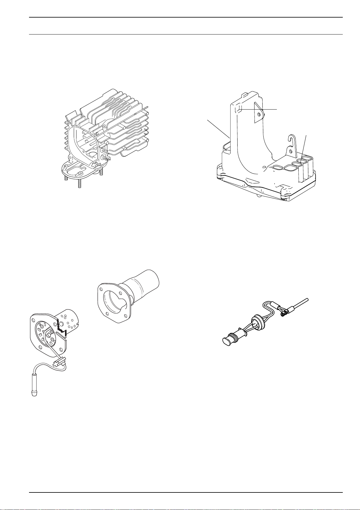
Fig. 204 Heat exchanger . . . . . . . . . . . . . . . . . . . . . . . . . . . . . . . . . . . . . . . . . . . . . . . . . . . . . . . . . . . . . . . . . . . . . . 202
Fig. 205 Burner with combustion chamber . . . . . . . . . . . . . . . . . . . . . . . . . . . . . . . . . . . . . . . . . . . . . . . . . . . . . . . . 202
Fig. 206 Control unit. . . . . . . . . . . . . . . . . . . . . . . . . . . . . . . . . . . . . . . . . . . . . . . . . . . . . . . . . . . . . . . . . . . . . . . . . 202
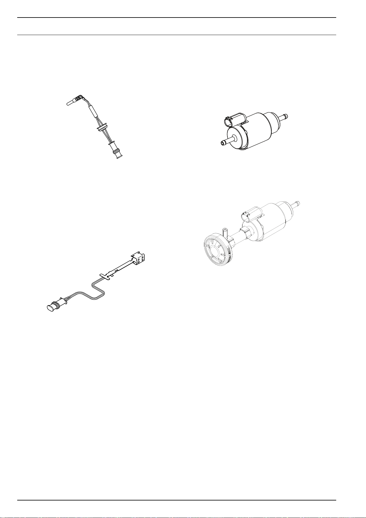
Fig. 207 Flame monitor. . . . . . . . . . . . . . . . . . . . . . . . . . . . . . . . . . . . . . . . . . . . . . . . . . . . . . . . . . . . . . . . . . . . . . . 202
Fig. 208 Glow plug . . . . . . . . . . . . . . . . . . . . . . . . . . . . . . . . . . . . . . . . . . . . . . . . . . . . . . . . . . . . . . . . . . . . . . . . . . 203
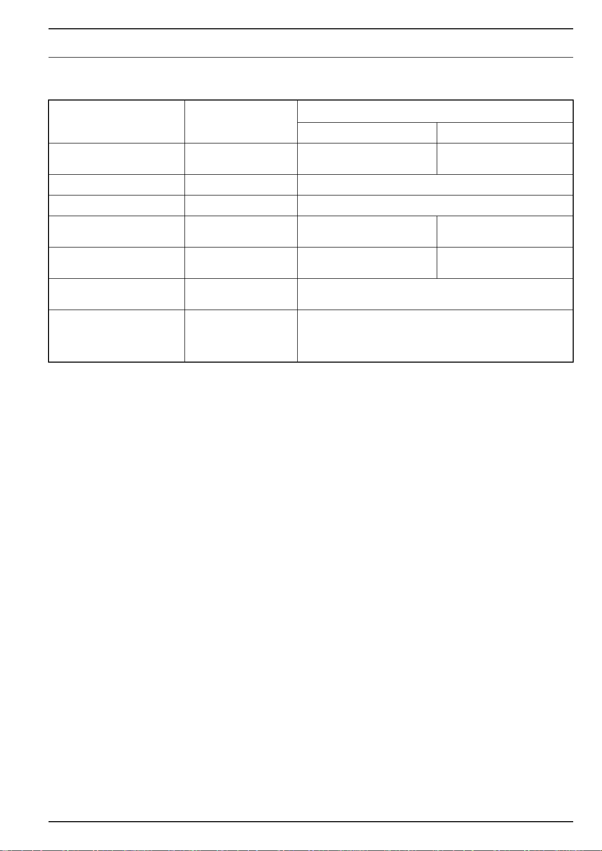
Fig. 209 Overheating sensor . . . . . . . . . . . . . . . . . . . . . . . . . . . . . . . . . . . . . . . . . . . . . . . . . . . . . . . . . . . . . . . . . . . 203
Fig. 210 Fuel pump DP42 (petrol) . . . . . . . . . . . . . . . . . . . . . . . . . . . . . . . . . . . . . . . . . . . . . . . . . . . . . . . . . . . . . . . 203
Fig. 211 Fuel pump DP42 (diesel) with diaphragm damper . . . . . . . . . . . . . . . . . . . . . . . . . . . . . . . . . . . . . . . . . . . . 203
Fig. 401 Technical Data Air Top 2000 STC. . . . . . . . . . . . . . . . . . . . . . . . . . . . . . . . . . . . . . . . . . . . . . . . . . . . . . . . . 401
Fig. 402 Setpoints Air Top 2000 STC. . . . . . . . . . . . . . . . . . . . . . . . . . . . . . . . . . . . . . . . . . . . . . . . . . . . . . . . . . . . . 402
Fig. 501 General fault symptoms . . . . . . . . . . . . . . . . . . . . . . . . . . . . . . . . . . . . . . . . . . . . . . . . . . . . . . . . . . . . . . . 501
Fig. 502 Fault symptoms during operation . . . . . . . . . . . . . . . . . . . . . . . . . . . . . . . . . . . . . . . . . . . . . . . . . . . . . . . . 502
Fig. 603 Component overview . . . . . . . . . . . . . . . . . . . . . . . . . . . . . . . . . . . . . . . . . . . . . . . . . . . . . . . . . . . . . . . . . 602
Fig. 601 Characteristic resistance values of an overheating temperature sensor . . . . . . . . . . . . . . . . . . . . . . . . . . . . 611
Fig. 701 Connector assignments . . . . . . . . . . . . . . . . . . . . . . . . . . . . . . . . . . . . . . . . . . . . . . . . . . . . . . . . . . . . . . . . 701
Fig. 702 System wiring diagram Air Top 2000 STC, 12 V/24 V with rotary switch . . . . . . . . . . . . . . . . . . . . . . . . . . . 702
Fig. 703 Systems wiring diagram Air Top 2000 STC, 12 V/24 V with MultiControl. . . . . . . . . . . . . . . . . . . . . . . . . . . 702
Fig. 704 System wiring diagram Air Top 2000 STC D, 12 V/24 V ADR operation with SmartControl . . . . . . . . . . . . . 703
Fig. 705 System wiring diagram Air Top 2000 STC D, 12 V/24 V ADR operation with rotary switch . . . . . . . . . . . . . 703
Fig. 706 System wiring diagram Air Top 2000 STC, 12 V/24 V with combination timer . . . . . . . . . . . . . . . . . . . . . . . 704
Fig. 801 Fuel line lengths, inside diameter and height differences (fuel tank, heater) to fuel pump . . . . . . . . . . . . . . 802
Fig. 802 Fuel take-off via tank drain plug (plastic or metal fuel tank). . . . . . . . . . . . . . . . . . . . . . . . . . . . . . . . . . . . . 803
Fig. 803 Webasto tank extracting device (plastic fuel tank) . . . . . . . . . . . . . . . . . . . . . . . . . . . . . . . . . . . . . . . . . . . . 803
Fig. 804 Webasto tank extracting device (metal fuel tank) . . . . . . . . . . . . . . . . . . . . . . . . . . . . . . . . . . . . . . . . . . . . 803
Fig. 805 Pipe/hose connections. . . . . . . . . . . . . . . . . . . . . . . . . . . . . . . . . . . . . . . . . . . . . . . . . . . . . . . . . . . . . . . . . 804
Fig. 806 DP42 fuel pump (installation position, petrol) . . . . . . . . . . . . . . . . . . . . . . . . . . . . . . . . . . . . . . . . . . . . . . . 804
Fig. 807 DP42 fuel pump, installation position, diesel . . . . . . . . . . . . . . . . . . . . . . . . . . . . . . . . . . . . . . . . . . . . . . . . 804
Fig. 808 Fuel filter. . . . . . . . . . . . . . . . . . . . . . . . . . . . . . . . . . . . . . . . . . . . . . . . . . . . . . . . . . . . . . . . . . . . . . . . . . . 805
Fig. 809 Exhaust silencer. . . . . . . . . . . . . . . . . . . . . . . . . . . . . . . . . . . . . . . . . . . . . . . . . . . . . . . . . . . . . . . . . . . . . . 805
Fig. 810 End of exhaust pipe, installation position. . . . . . . . . . . . . . . . . . . . . . . . . . . . . . . . . . . . . . . . . . . . . . . . . . . 806
Fig. 811 Removing mounting plate on fuse holder . . . . . . . . . . . . . . . . . . . . . . . . . . . . . . . . . . . . . . . . . . . . . . . . . . 806
Fig. 812 Fuse holder, installation position . . . . . . . . . . . . . . . . . . . . . . . . . . . . . . . . . . . . . . . . . . . . . . . . . . . . . . . . . 806
Fig. 813 Rotary switch control element . . . . . . . . . . . . . . . . . . . . . . . . . . . . . . . . . . . . . . . . . . . . . . . . . . . . . . . . . . . 807
Fig. 814 Disconnecting the connector. . . . . . . . . . . . . . . . . . . . . . . . . . . . . . . . . . . . . . . . . . . . . . . . . . . . . . . . . . . . 807
Fig. 815 Installation example of heater in recirculated air mode . . . . . . . . . . . . . . . . . . . . . . . . . . . . . . . . . . . . . . . . 808
Fig. 901 Installing an external room temperature sensor . . . . . . . . . . . . . . . . . . . . . . . . . . . . . . . . . . . . . . . . . . . . . . 901
Fig. 902 Removing / fitting casing parts . . . . . . . . . . . . . . . . . . . . . . . . . . . . . . . . . . . . . . . . . . . . . . . . . . . . . . . . . . 903
Fig. 903 Replacing control unit, combustion air fan and overheating temperature sensor . . . . . . . . . . . . . . . . . . . . . 906
Fig. 904 Changing glow plug, replacing flame monitor, burner and heat exchanger . . . . . . . . . . . . . . . . . . . . . . . . . 908
Fig. 905 Starting air hole in burner . . . . . . . . . . . . . . . . . . . . . . . . . . . . . . . . . . . . . . . . . . . . . . . . . . . . . . . . . . . . . . 910
IV
Page 7

Air Top 2000 STC 1 Introduction
1 Introduction
1.1 Contents and purpose
This workshop manual is designed to assist trained personnel
in repairing both the petrol and the diesel versions of the Air
Top 2000 STC air heaters.
1.1.1 Use of air heaters
The Webasto Air Top 2000 STC air heaters are designed:
– to heat cabins, boats, commercial vehicles, minibusses,
vans/transporters, ambulances and motor homes.
– to defrost vehicle windows.
They are not approved for heating cargo areas used to carry
dangerous goods/hazardous substances.
The heaters operate independently of the engine and are
connected directly to the fuel tank and the electrical system
of the vehicle.
They may be used for vehicles with either water or air-cooled
engines.
1.2 Meaning of signal words
Throughout this manual, the signal words CAUTION, ATTEN-
ION and NOTE have the following meanings:
T
CAUTION
This signal word is used to highlight operating instructions or
procedures which, if not followed or not followed correctly,
may result in personal injury or fatal accidents.
ATTENTION
This signal word is used to highlight operating instructions or
procedures which, if not followed or not followed correctly,
may result in damage to the equipment or its components.
NOTE
This signal word is used to draw your attention to a special
feature.
1.2.1 General safety information
The mouth of the exhaust pipe should be installed facing
ownwards, to the side or, if the exhaust pipe passes under
d
the floor of the vehicle, up to the side or rear limit of the
driver's cab or of the vehicle.
The function of important parts of the vehicle must not be
adversely affected. It must not be possible for condensation
or water to collect in the exhaust pipe. Drain holes may be
used.
The electrical cables, switchgear and control units for the
heater must be arranged in the vehicle such that their function is not impaired under normal operating conditions.
Compliance with §§ 45 and 46 StVZO (German road vehicle
registration regulation) must be ensured for the installation
of fuel lines and the installation of additional fuel tanks.
The main points of this regulation:
– Fuel lines must be designed in such a way that torsion in
the vehicle, engine movements and similar do not have a
negative effect on their durability. They must be
protected from mechanical damage.
– Parts that carry fuel must be protected from heat that
could adversely affect their function and positioned such
that dripping or evaporating fuel cannot collect or ignite
on hot parts or on electrical equipment.
The heat exchanger of the air heater can be used for a
maximum period of 10 years and must then be replaced
with a genuine spare part by the manufacturer or an
authorised workshop. A label must then be affixed to
the heater showing the date of sale and the wording
"Genuine Spare Part".
When you change the heat exchanger it is also necessary that
you replace the overheating protection element (overheating
sensor) to prevent possible malfunctions caused by using the
old overheating sensor.
The Air Top 2000 STC heaters are prepared for interior installation and and sealing directly on the driver's cab floor or
wall. Non-release connections must be used in the interior for
combustion air and exhaust pipes for Webasto accessories.
The seal between the heater mounting and the vehicle floor
must always be installed otherwise harmful exhaust gases
may get into the vehicle interior.
The heating air and combustion air intake openings must be
positioned in such a way that no water can enter them when
the vehicle is driven through water at permissible levels.
The heater must not be installed in the driver's or passenger's
compartment of busses (vehicle class M2 and M3). If the
heater is nevertheless installed in such a place, the casing
must be tightly sealed from the vehicle interior. The casing
must have sufficient external ventilation to ensure a maximum temperature of 40 °C is not exceeded in the box. Faults
may occur if the temperature exceeds this level.
Due to the risk of explosion, the heater must be switched off
at filling stations and facilities.
Due to the risk of explosion, the heater must be switched off
wherever inflammable vapours or dust can form (e.g. in the
vicinity of fuel, coal, wood dust or grain stores or similar).
Due to the risk of asphyxiation and poisoning, the heater
must not be operated in enclosed areas such as garages and
workshops without an emissions extraction system even if
you use the timer.
101
Page 8

1 Introduction Air Top 2000 STC
Overheating
In the event of prolonged smoke accumulation, unusual combustion noise or smell of fuel, the heater must be shut down
by removing the fuse and must not be started again until it
has been examined by Webasto-trained personnel. Liability
claims can only be asserted for proven compliance with the
maintenance and safety information by the claimant.
Installation regulations for Webasto fuel tanks for supplying
fuel to heaters in vehicles:
• The tanks must not be installed in the passenger's
compartment or driver's cab of busses.
• The fuel filler neck must not be inside the passenger's
compartment or driver's cab in any vehicle.
• Petrol fuel tanks must not be installed directly behind the
front panelling of the vehicle. They must be separated
from the engine in such a way that in the event of an
accident the fuel cannot ignite. This does not apply to
tractor units with an open driver's seat.
Due to the potential fire risk, the fuel lines (Mecanyl hose)
must not make direct contact with the exhaust pipe and must
be thermally insulated wherever necessary.
All fuel pipes must have sealed connections, they must not be
damaged in any way and must be checked at regular intervals
(at least at the same intervals as the vehicle inspection).
Keep the heating air inlet and heating air outlet free of dirt
and foreign objects. Dirty, blocked air lines can cause the
heater to shut down due to overheating.
After the heater has shut down due to overheating, check
that the air system is clear, remove any materials that may
block the air flow and have any damage to the air lines
repaired by an authorised Webasto workshop. The heater
lock-out can then be cancelled by switching the heater off
and on again. If this action does not produce the required
success (if the heater overheats again), take it to a Webasto
authorised workshop. Never remove the grill over the air inlet
of the heater.
The air outlet jets or air vents with adjustable flaps must
always be opened by a certain extent so that the air flow
through the heater is not completely blocked. At least one air
vent must be unclosable.
If the heater is installed in a storage area you must ensure
that no flammable substances are kept in this area and that
other material does not restrict the air supply to the heater.
Air lines must be securely fixed to the heater (pipe clips) and
all other connection points (vents).
ATTENTION
The points described below must be avoided:
NOTE
If any damage or leaks are found on the fuel line, the heater
must not be used until the damage has been rectified by an
authorised Webasto workshop.
Put the heater out of action by removing the fuse.
• Do not step on the heater and do not place or throw any
heavy objects onto the heater.
• Do not place any items of clothing, fabrics or similar
materials over the heater or in front of the heating air
intake side and the heating air outlet.
• The flow of hot air from the heater must not be restricted
or blocked by highly flammable substances or materials
such as rags, cleaning wool etc.
• Flammable or explosive substances and gasses must not
be placed near or in contact with the heater, the hot air
line, the hot air flow or the exhaust pipe.
• The heater must not be cleaned with a high-pressure
cleaner.
• Do not frequently switch off the heater at the main
battery switch or battery disconnector otherwise the
heater may suffer long-term damage and malfunctions.
NOTE
Failure to follow the installation instructions and the notes
contained therein will lead to all liability being refused by
Webasto.
The same applies if repairs are carried out incorrectly or with
the use of parts other than genuine spare parts. This will
result in the invalidation of the type approval for the heater
and therefore of its homologation / EC type licence.
102
Carefully read the operating instructions before operating the
heater.
Page 9

Air Top 2000 STC 1 Introduction
Page for notes
103
Page 10
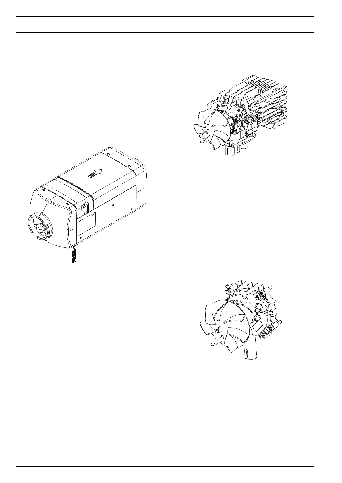
2 General description Air Top 2000 STC
2 General description
The Air Top 2000 STC air heater is based on the evaporator
principle and essentially consists of:
– Drive unit (combustion air fan, heating air fan and drive
motor)
– Heat exchanger
– Burner with combustion chamber
– Control unit
– Glow plug
– Housing parts
– Base seal
Fig. 202 Air Top 2000 STC air heater without casing
2.1 Drive unit
The drive unit consists of the drive motor, combustion air fan,
eating air fan and the intake casing.
h
The combustion air fan supplies the air required for the
combustion process through the combustion air inlet into the
combustion chamber.
The heating air fan feeds the hot air from the hot air inlet via
the heat exchanger to the hot air outlet.
Fig. 201 Air heater Air Top 2000 STC
The following control and monitoring components are
integrated in the heater:
– Control unit with room temperature sensor
– Flame monitor (petrol heater only)
– Glow plug
– Overheating sensor
All Air Top 2000 STC heaters can also be controlled using an
optional external room temperature sensor.
The fuel is supplied from the external fuel tank by a fuel
pump.
Fig. 203 Drive unit
201
Page 11
Air Top 2000 STC 2 General description
Combustion
chamber
Burner
Wiring
harness
Internal
room temperature
sensor
Component plug
2.2 Heat exchanger
In the heat exchanger, the heat generated by the combustion
process is transferred to the air delivered by the heating air
fan.
Fig. 204 Heat exchanger
2.3 Burner with combustion chamber
2.4 Control unit
The control unit is the central component for ensuring
t
rouble-free operation. It monitors the components,
evaluates the sensor signals and controls heating operation.
Fig. 206 Control unit
In the burner, the fuel is distributed over the metal fibre
vaporator (mesh) in the combustion chamber. The fuel/air
e
mixture burns in the combustion chamber, thus heating the
heat exchanger.
Fig. 205 Burner with combustion chamber
2.5 Flame monitor (petrol heater only)
The flame monitor is a low-impedance PTC resistor which
hanges its resistance as a function of the heat emitted by the
c
flame.
This change in resistance is evaluated by the control unit so
that the flame status is monitored throughout the heating
operation.
Fig. 207 Flame monitor
202
Page 12
2 General description Air Top 2000 STC
2.6 Glow plug
The fuel/air mixture is ignited by the glow plug when the
heater is started. The glow plug is designed as an electrical
resistor and is positioned in the burner on the side opposite
the flame.
Fig. 208 Glow plug
2.7 Overheating sensor
The overheating sensor measures the temperature in the fin
rea of the heat exchanger while the heater is operating. The
a
control unit evaluates the signal, regulates the heating air
outlet temperature and controls the overheating shut-down
function.
.
2.8 Fuel pump
The fuel pump is a combined delivery, metering and a shuto
ff system for supplying fuel to the heater. The Air Top 2000
STC heater must be operated with the fuel pump DP 42.
Fig. 210Fuel pump DP42 (petrol)
Fig. 209 Overheating sensor
Fig. 211Fuel pump DP42 (diesel) with diaphragm damper
203
Page 13

Air Top 2000 STC 2 General description
Page for notes
204
Page 14

3 Function description Air Top 2000 STC
3 Functional description
3.1 Control element
The control element is used to:
• Switch the heater on and off.
• Set the required room temperature (intake temperature
between approx. 5 °C and 35 °C).
• Reset the heater after a malfunction.
• Display fault codes:
– Control elements with display: the fault code is
shown on the display.
– Control elements without display: the fault code is
indicated by the indicator lamp flashing in defined
sequences.
NOTE
ADR operation:
The heater is in ADR lock-out mode after an ADR shutdown.
This mode is cancelled after switching the heater off and on
again.
3.2 Switching on
Set the control element to the required temperature.
he heater will start up if the heating air temperature is lower
T
than the set temperature.
NOTE
Only the heating air fan will start up if the room temperature
is higher than the set temperature.
The heating air fan will not start up if an external room tem-
perature sensor is connected.
The flame monitor is checked. If the flame monitor now signals "light", the system will attempt to cool the flame monitor
for 60 seconds. If the flame monitor still signals "light" the
control unit will be locked out. If there is a malfunction in any
another monitored component fault lock-out will take place
with no afterrunning period.
Automatic restart
The starting procedure will be repeated if no flame is
detected. The glow plug is switched on again (clocked). The
motor of the heating and combustion air fan is set to approx.
25% of its maximum speed.
The fuel pump starts after approx. 30 seconds (petrol) or 50
seconds (diesel) and the flame begins to form. After a further
65 seconds (petrol) or 90 seconds (diesel) the glow plug is
switched off and the presence of a flame established.
If the heater again fails to ignite properly, after a 180 second
fault afterrun phase at maximum speed the heater will be
shut down and is in fault lock-out mode.
NOTE
The heater will assume fault lock-out mode after a restart.
Briefly switch the heater off and on (for at least 2 seconds) to
reset fault lock-out.
3.3 Heating mode
Combustion gasses flow through the heat exchanger during
heater operation. The combustion heat is transferred to the
walls of the heat exchanger, absorbed by the heating air
blown in by the heating air fan and blown into the vehicle
interior.
The temperature of the heating air intake is measured by a
room temperature sensor on the intake side of the heater or
an external room temperature sensor. If the measured temperature is lower than the value set on the control element,
the heating capacity will be increased to maximum.
To extend the service life of the burner the delivery rate from
the fuel pump is reduced for 10 seconds every 10 minutes
during continuous operation.
In addition, heating mode is interrupted every 8 hours in the
same way as for a control pause.
Start
When the heater is switched on, the ON indicator lamp
comes on and the glow plug is switched on (clocked). The
motor of the heating and combustion air fan is set to approx.
50% of its maximum speed.
The fuel pump starts after approx. 40 seconds and the flame
begins to form. To improve the starting characteristics, the
fuel pump and the combustion air fan are started at different
frequencies and speeds.
After a further 95 seconds (petrol) or 110 seconds (diesel) the
glow plug is switched off and the presence of a flame established.
301
3.4 Control mode
In control mode, the speed of the heating and combustion air
an and the fuel pump delivery rate are dependent on the
f
heating capacity. The glow plug is switched off.
3.5 Control pause
The heating capacity is reduced on reaching the temperature
set on the control element. The speed of the heating and
combustion air fan and the delivery rate of the fuel pump are
reduced.
Page 15

Air Top 2000 STC 3 Function description
If, at minimum heating capacity, the intake temperature set
on the control element is exceeded, the fuel pump will be
shut down and combustion stops. To allow the flame to burn
out properly, the speed of the heating and combustion air fan
drops to partial load speed after 20 seconds, returns to the
initial speed after 15 seconds and then drops to the control
pause speed after 3 minutes where it remains during the
entire control pause phase.
The control pause speed for boat heaters is 0.
The heater will restart if the temperature at the room temperature sensor drops below the set temperature.
NOTE
Changes to the settings on the control element are implemented by the control unit/heater with a time delay.
3.6 Switching off
The ON indicator lamp on the control element goes out when
he heater is switched off. If no fuel has yet been delivered or
t
if the heater is in control pause mode, the heater will be
switched off immediately with no afterrunning period.
If fuel delivery has already begun it will stop immediately
when the heater is switched off. The heater is switched off in
the same way as the transition from control mode to control
pause. The heater is then switched off automatically.
NOTE
It is possible to switch the heater back on during the afterrunning period. In this case, afterrunning is completed and the
heater is then restarted.
3.7 Heater functions in ADR vehicles
NOTE
O
nly for Air Top 2000 STC diesel heaters that are installed in
vehicles for transporting dangerous goods (ADR):
Afterunning period will remain unchanged if the heater is
switched off at the control element.
A brief afterrunning period (max. 40 seconds) is started automatically when:
• The vehicle's engine is shut down
• A pumping device is placed into operation.
The control unit is in "fault lock-out" mode after an ADR shutdown. The control element must be set to "OFF" before starting up again.
3.8 Fault switch-off
The control unit detects faults in individual heater compo-
ents and malfunctions during start-up and operation. The
n
heater shuts down and assumes fault lock-out when:
• No repeated or faulty start-up
• Room temperature sensor defective
• Overheating sensor interrupted or short-circuited
• Overheating sensor installed incorrectly
• Glow plug interrupted or short-circuited
• Drive motor overloaded or blocked or short-circuited or
interrupted
• Flame monitor interrupted or short circuited
• Fault in fuel pump electrical circuit or in overheating
protection (only during start phase)
• Undervoltage below 10.5 V/21 V for longer than 20
seconds
• Overvoltage above 16 V/32 V for longer than 6 seconds
• Control unit defective
The fuel supply shuts down in the event of overheating. The
heater continues to run (afterrunning period) as when
switched off manually. Following the afterrunning period the
control unit is in fault lock-out mode if the count of the overheating counter is greater than the value programmed in the
data set (currently 20).
• Control element with display: the overheating fault code
is shown on the display.
• Control element without display: the overheating fault
code is indicated by the operating indicator flashing in
defined sequences.
Rectify fault.
Briefly switch the heater on and off (for at least 2 seconds) to
reset fault lock-out.
302
Page 16

3 Function description Air Top 2000 STC
3.8.1 Fault monitoring
Overheating, incorrect start and flame failure faults are
counted and, after the maximum number of permissible
faults have been exceeded, result in heater lock-out.
The incorrect start counter is incremented by 1 each time the
heater fails to start and decremented by 1 each time it starts
correctly, but never falls below 0. If the incorrect start counter reaches the maximum permissible value of 7, this indicates that the heater is in heater lock-out mode (HGVP).
The fault counter is incremented by 1 for each malfunction,
which does not have its own counter. The fault counter is
reset to 0 at the start of control mode. If the fault counter
reaches the maximum permissible value of 10, this indicates
that the heater is in heater lock-out mode.
The overheating counter is incremented by 1 each time the
heater overheats. If the overheating counter reaches the
maximum permissible value of 20, this indicates that the
heater is in heater lock-out mode.
The flame interruption counter (FAZ) is incremented by 1
each time the flame fails during heating mode. The counter
is decremented by 1 each time the heater assumes control
mode.
If the flame interruption counter reaches a value of 3 the
heater will assume fault lock-out mode and the permanent
flame interruption counter is incremented by 1. In control
mode, the permanent flame interruption counter is decremented by 1. When the heater is burning properly again, the
permanent flame interruption counter will return to 0 after a
few control cycles. If the permanent flame interruption counter exceeds the maximum permissible value of 3, the heater
will assume heater lock-out mode.
3.8.2 Resetting fault switch-off
1. Switch on the heater
2. There is a fault and it is detected by the control unit
as a malfunction
3. The fault code is shown on the control element
4. If set, cancel heater lock-out (as described in the fol-
lowing)
4.1. The heater detects a fault as a malfunction
4.2. Fault switch-off followed by fault lock-out
4.3. The fault code is shown on the control element
5. Switch off the heater
6. Determine cause of fault (e.g. with or without fault
code, visual inspection of fuses and plug connections,
...)
7. Rectify fault
8. Switch on the heater
9. Reset fault lock-out
10. The heater assumes control mode
Certain faults add to the fault count in the fault code mem-
ry. The heater assumes heater lock-out mode when the
o
number of faults in the fault code memory exceeds a limit
value. The maximum number of fault in the fault code memory and the limit value of the fault code memory is defined by
Webasto.
303
Reset heater lock-out
Heater lock-out can be reset:
– With Webasto Thermo Test PC diagnostics (WTT)
– or by switching on the heater.
Pull fuse F1 for at least 10 s.
Switch off the heater.
Reinsert fuse F1.
Switch on the heater.
Reset permanent heater lock-out
Only for "OE" heater variants that are integrated in bus sys-
tems.
The lock-out can only be released with the vehicle-specific
computer diagnosis system.
Page 17

Air Top 2000 STC 3 Function description
Page for notes
304
Page 18

4 Technical Data Air Top 2000 STC
4 Technical data
Wherever no limit values are specified, the technical data in
the table refer to the standard heater tolerances of ±10% at
an ambient temperature of +20 °C and at rated voltage
under standard conditions.
Fuel for Air Top 2000 STC B (petrol):
The fuel in accordance with DIN EN 228 as specified by the
vehicle manufacturer should be used.
Fuel for Air Top 2000 STC D (diesel/FAME):
The diesel fuel in accordance with DIN EN590 specified by the
Electrical components:
The control unit, drive motor for heating air and combustion
air fan as well as the glow plug are designed for 12 Volt or
24 Volt.
vehicle manufacturer must be used. Class EL fuel oil (not L
fuel oil) can also be used provided it complies with the normal
quality as per DIN 51603 available in the German market.
There are no known adverse effects of using additives.
The temperature sensor and flame monitor (only petrol
heater) are not designed for specific voltages.
If fuel is taken from the vehicle's fuel tank, follow the additive
instructions issued by the vehicle manufacturer.
When changing to low-temperature fuel, the heater must be
4.1 General technical data
Heater Op
Type approval EMC
Design Air heater with evaporator burner
Heat flow Control range 1.0 - 2.0 kW 0.9 - 2.0 kW
eration Air Top 2000 STC B Air Top 2000 STC D
E1 R10- 04 1085
Heater
E1 R122- 00 0216
Fuel Petrol
DIN EN 228
DIN 51625
Fuel consumption Control range 0.1 - 0.2 kg/h (0.14 - 0.27 l/h) 0.1 - 0.21 kg/h (0.12 - 0.24 l/h)
Rated voltage 12 Volt 12 / 24 Volt
Operating voltage range 10.5 - 16 Volt 10.5 - 16 / 20.5 - 31 Volt
Rated power consumption Control range 14-29 W
Permissible ambient temperature:
Heater: - Operation
- Storage
Fuel pump: - Operation
- Storage
Permissible combustion air intake temperature
Adjustment range for interior temperature
Volumetric heating air flow rate
at motor speed
CO2 in exhaust gas (permitted function
range)
-40 to + 20 °C (petrol), -40 to + 30 °C (diesel),
Control range +5 to + 35 °C
at 0.5 mbar max. 93 m3/h
1 kW
2 kW
5.0 - 8.0 %
9.0 - 12.5 %
-40 to + 40 °C
-40 to + 85 °C
-40 to + 85 °C
-40 to + 20 °C
t 4750 U/min
a
Diesel/FAME
DIN EN 590
DIN 51603
DIN EN 14214
5.0 ... 8.0 %
9.0 ... 12.5 %
Heater dimensions Length 311 ± 2 mm
Width 120 ± 1 mm
Height 121 ± 1 mm
Weight 2.6 kg
Fig. 401 Technical Data Air Top 2000 STC
401
Page 19
Air Top 2000 STC 4 Technical Data
4.1 Setpoints
Heater Operation Air Top 2000 STC B and Air Top 2000 STC D
12 Volt 24 Volt
Glow plug At 25 ºC
Test current: < 5 mA
Drive motor Outside < 6 Ohm
Overheating temperature sensor at 25 ºC 2 - 2.5 Ohm
Undervoltage shut-down
(tripping time > 20 s )
Overvoltage shut-down
(tripping time > 6 s )
Flame monitor (cold test) At 25 ºC
Test current: < 5 mA
Flame monitor (hot test) At 800 – 1000 °C
Test current: < 5 mA
(ceramic rod red-hot over
approx. 20 mm length)
Red mark
0.263 - 0.323 Ohm
≤ 10.5 V ≤ 20.5 V
≥ 15 V ≥ 31 V
Green mark
1.125 - 1.375 Ohm
2.6 - 3.4 Ohm
12 - 15 Ohm
Fig. 402 Setpoints Air Top 2000 STC
402
Page 20

4 Technical Data Air Top 2000 STC
Page for notes
403
Page 21

Air Top 2000 STC 5 Troubleshooting
5 Troubleshooting
5.1 General information
This section describes how to identify and remedy faults in
the Air Top 2000 STC heater.
If a malfunction occurs, a fault code will be shown on the
display or the ON indicator lamp will flash (on control
elements with no display). The heater can be additionally
checked with a personal computer (see operating
instructions for Webasto Thermo Test PC Diagnostics).
ATTENTION
Troubleshooting assumes detailed knowledge of the design
and functional principle of the individual heater components
and must only be carried out by specifically trained personnel.
If in doubt, refer to Section 2 and 3 for information on how
the functions interact.
NOTE
For ADR operation only
The control unit is in "fault lock-out" mode after an ADR
shutdown or the operating voltage has been applied by
switching on the main switch in the vehicle and setting the
control element to ON. Before restarting the heater, the
control element must be set to "OFF" or the Quick Heat
button on the combination timer pressed.
ATTENTION
Troubleshooting is generally restricted to locating faulty
components. The following potential sources of malfunction
are not taken into account as they should always be checked
to rule them out as the cause of fault:
• Corroded connectors
• Loose plug connectors
• Poor crimp contacts on connectors
• Corroded cables and fuses
• Corroded battery terminals
The electrical plug connections at the control unit must be
disconnected to check individual components.
Carry out a function check in the vehicle after rectifying after
each fault.
5.2 General fault symptoms
The following table (Fig. 501) lists the possible fault symptoms.
ault symptom Possible cause Corrective measures
F
Heater cuts out automatically No combustion after start
and restart
ON indicator lamp flashes
Flame goes out during operation
ON indicator lamp flashes
Heater overheating
ON indicator lamp flashes
Battery voltage too low
ON indicator lamp flashes
Heater emits black smoke Combustion air and/or exhaust system
blocked
Briefly switch heater off and on again
Briefly switch heater off and on again
Check heating air routing for free
passage, allow heater to cool,
briefly switch heater off and on again
Charge battery
Briefly switch heater off and on again
Check combustion-air and exhaust-gas
routing for free passage
Fig. 501 General fault symptoms
501
Page 22

5 Troubleshooting Air Top 2000 STC
5.3 Fault symptoms during operation
The following table (Fig. 502) lists the possible fault
symptoms during operation which should be checked first.
In the event of a malfunction, the fault is to be located and
rectified with the aid of this table. It is important to ensure
that the fault symptom is clearly identified.
Fault symptom Occurrence Possible cause
Heater will not start and LED on control
element not lit
Heater will not start, but LED lit Immediate The heater immediately assumes control pause mode
NOTE
A fault code can be shown as follows:
• MultiControl and SmartControl control element:
The malfunction is shown in the form of a fault code which begins with F and a hexadecimal combination of numbers
and/or letters (F HEX).
See “5.4 Fault code output (hexadecimal / Webasto Thermo Test)” on Page 503.
• Control elements with display (not MultiControl/SmartControl):
The malfunction is shown in the form of a fault code which begins with F and a two-number combination (FXX).
See “5.5 Fault code output (flashing or FXX output)” on Page 506.
• Control elements with indicator lamp:
the malfunction is indicated in the form of a flash code. After 5 fast flash pulses, the fault code is output by a sequence
of long flash pulses. The long flash pulses must be counted.
See “5.5 Fault code output (flashing or FXX output)” on Page 506.
Immediate Incorrect wiring, defective fuse
Fig. 502 Fault symptoms during operation
If the fault symptom is not included in this table, or if the
malfunction cannot be found under the specific fault
symptom, the fault can be determined by means of the fault
codes as described in the following tables (Section 5.4 and
5.5).
In an emergency you can contact our technicians on our
Service Hotline.
when switched on; the control pause speed for a boat
heater is 0 rpm.
502
Page 23

Air Top 2000 STC 5 Troubleshooting
5.4 Fault code output (hexadecimal / Webasto Thermo Test)
Fault code
output:
HEX
00 No error No error No action necessary
01 Defective control unit
02 No start
Fault message Fault details Recommended measures
Defective control unit, wrong end-
of-line programming or coolant
temperatur sensor (at water
heaters) failure
After start-up has been repeated,
combustion still fails to occur
1) Check for fault in air intake and
2) Check for fault in fuel system
3) Check fuel pump
4) Electrical check of glow plug
Replace control unit
exhaust systems
03 Flame failure
04 Supply Voltage too high
05
06 Heating unit overheated
07 Heater lock-out Heater interlocked
Flame was detected prior to
combustion
The flame went out during
operation and combustion.
Supply voltage was too long above
maximum threshold value
Flame detector signals flame
before combustion operation
Overheat protection has been
activated or the temperature at the
heat exchanger has exceeded the
upper limit
See error 02
Check system voltage
1) Check for fault in air intake,
exhaust systems
2) Check for fault in fuel system
3) Check fuel pump
4) Electrical check of glow plug
1) Check for fault in air intake/blow-
out side, exhaust systems
2) Check for fault in fuel system
1) Reset heater lock-out and attempt
restart
2) Read out further fault messages
and work through instructions
Reset heater lock-out: switch on
heater. Pull fuse F1 for at least 10 s.
Switch off heater. Reinsert fuse F1.
Switch on the heater.
NOTE
Following fault occurred several
imes:
t
Fault counter: > 10x
False start counter: > 7x
Overheating counter: > 20x
08 Fuel pump short circuit
09
11 Wrong fuel coding
Combustion air fan short
circuit
Fuel pump has short circuit to
ground
Combustion air fan has short
circuit to ground
Incorrect parameter block or
wrong heater (diesel/gasoline)
used
Electrical check of fuel system
Electrical check of combustion air fan
motor
Replace control unit
503
Page 24

5 Troubleshooting Air Top 2000 STC
Fault code
output:
HEX
12
Fault message Fault details Recommended measures
1) Check for fault in area of W-bus
W-bus communication
failure
W-Bus communication failure
communication/W-bus control
element/W-bus Telestart
2) Replace control unit
14
15 Combustion air fan blocked Combustion air fan is blocked
17
18
19
81 EOL checksum error Checksum of EOL dataset is wrong Replace control unit
82 No start during test-run No start during test-run See error 02
83 Flame failure
84 Operating voltage too low
Temperature sensor short
circuit (internal, external)
Gradient exceedance
overheat protection
Communication failure on
customer specific bus
Glow plug / flame monitor
short circuit
Temperature sensor has short
circuit to ground
The temperature rise at the heat
exchanger has exceeded the upper
limit.
Communication failure on
customer specific bus
Glow plug / electronic ignition unit
has short circuit to ground
Flame interruption during
combustion operation, more than
FAZ (EEPROM) times.
Supply voltage was too long below
maximum threshold value
Electrical check of external/internal
temperature sensor
1) Check for fault in fan motor
2) Heating air intake fan wheel
snagging or jammed
3) Combustion air intake fan wheel
snagging or jammed
Check for fault in air intake/blow-
out side, exhaust systems
-
Electrical check of glow plug
See error 02
Check system voltage
88 Fuel pump interruption
89
91 Wrong control unit coding
92 Command refresh failure Command refresh failure
94
97
99
0 A
1 A Flame sensor short circuit
Combustion air fan
interruption
Temperature sensor
interruption (internal,
external)
Gradient undershooting
during start
Glow plug / electronic
ignition unit interruption
Glow plug / flame monitor
short circuit
Fuel pump interrupted or short
circuit to supply voltage UB
Combustion air fan interrupted or
short circuit to supply voltage UB
Control unit locked or coded as
neutral
Temperature sensor interrupted or
short circuit to supply voltage UB
Overheat sensor position wrong
(temperatur gradient too low)
Glow plug / electronic ignition unit
interrupted or short circuit to
supply voltage UB
Glow plug/Flame monitor circuit
has short circuit to ground
Flame sensor has short circuit to
ground
Electrical check of fuel system
Electrical check of fan motor
Replace control unit
Check for fault in area of W-bus
communication/W-bus control
element/W-bus Telestart
Electrical check of external/internal
temperature sensor
1) Check position of overheating
sensor
2) Check fuel supply system
Electrical check of glow plug
Electrical check of glow plug
Electrical check of flame monitor
504
Page 25

Air Top 2000 STC 5 Troubleshooting
Fault code
output:
HEX
Fault message Fault details Recommended measures
1B
8 A
9 A Flame sensor interruption
9B
AB
Overheat sensor short
circuit
Glow plug / electronic
ignition unit interruption
Setpoint potentiometer
interruption
Overheat sensor
interruption
The overheat sensor has a short
circuit to ground
Glow plug/Flame monitor
interrupted or short circuit to
supply voltage UB
Flame sensor interrupted or short
circuit to supply voltage UB
Setpoint potentiometer
interrupted or short circuit to
supply voltage UB
Overheat sensor interrupted or
short circuit to supply voltage UB
Electrical check of overheating sensor
Electrical check of glow plug
Electrical check of flame monitor
Electrical check of setpoint sensor
Electrical check of overheating sensor
505
Page 26

5 Troubleshooting Air Top 2000 STC
5.5 Fault code output (flashing or FXX output)
Fault code
output:
Flashing / FXX
F00 Defective control unit
F01 No start
F02 Flame failure
F03 Supply Voltage too high
Fault message Fault details Recommended measures
1) Check for fault in area of W-bus
Control unit defective
EOL programming error
No flame formed even after
repeated start attempt
The flame goes out during
operation and no longer reformed
after a restart attempt.
The operating voltage was higher
than the maximum permissible
value for too long
communication/W-bus control
element/W-bus Telestart
2) Replace control unit
1) Check for fault in air intake and
exhaust systems
2) Check for fault in fuel system
3) Check fuel pump
4) Electrical check of glow plug
See error 01
Check system voltage
F04
F05 Flame sensor interruption
F06
F07 Fuel pump interruption
F08
Flame was detected prior to
combustion
Temperature sensor
interruption (internal,
external)
Combustion air fan short
circuit
Combustion air fan blocked
The flame monitor detected a
flame before combustion started
There is a break or short to UB in
the electrical circuit of the flame
detector
There is a break or short to UB in
the temperature sensor
There is a break or short to UB in
the electrical circuit of the fuel
pump
The combustion air fan has a short
to ground or the fan motor is
overloaded
Combustion air fan blocking guard
has tripped
1) Check for fault in air intake,
exhaust systems
2) Check for fault in fuel system
3) Check fuel pump
4) Electrical check of glow plug
Electrical check of flame monitor
Electrical check of external/internal
temperature sensor
Electrical check of fuel system
Electrical check of combustion air fan
motor
1) Check for fault in fan motor
2) Heating air intake fan wheel
snagging or jammed
3) Combustion air intake fan wheel
snagging or jammed
F09
F10 Heating unit overheated
F11
506
Glow plug / electronic
ignition unit interruption
Overheat sensor
interruption
There is a break or short to UB in
the glow plug/ignition spark
generator
Overheating lock-out has tripped
(heater overheated)
There is a break or short to UB in
the electrical circuit of the
overheating sensor
Electrical check of glow plug
1) Check for fault in air intake/blow-
out side, exhaust systems
2) Check for fault in fuel system
Electrical check of overheating sensor
Page 27

Air Top 2000 STC 5 Troubleshooting
Fault code
output:
Flashing / FXX
F12 Heater lock-out Heater lock-out was activated
Fault message Fault details Recommended measures
1) Reset heater lock-out and attempt
restart
2) Read out further fault messages
and work through instructions
Reset heater lock-out: switch on
heater. Pull fuse F1 for at least 10 s.
Switch off heater. Reinsert fuse F1.
Switch on the heater.
NOTE
Following fault occurred several
imes:
t
Fault counter: > 10x
False start counter: > 7x
Overheating counter: > 20x
F14
F15
Gradient undershooting
during start
Setpoint potentiometer
interruption
Wrong position of overheating
sensor (overheating sensor
gradient too small)
There is a break or short to UB in
the electrical circuit of the setpoint
potentiometer
1) Check position of overheating
sensor
2) Check fuel supply system
Electrical check of setpoint sensor
507
Page 28

5 Troubleshooting Air Top 2000 STC
Page for notes
508
Page 29

Air Top 2000 STC 6 Function checks
Example of heater test bench
6 Function checks
6.1 General information
This section describes the checks conducted on the heater in
installed and uninstalled state to verify that it is in working
order.
CAUTION
The heater must not be operated in enclosed areas such as
garages and workshops without an emissions extraction
system.
ATTENTION
The complete testing of the heater and the control unit test
for "OEM" heaters are only possible together with the
vehicle.
6.2 Required test and measuring
quipment
e
The test and measuring equipment must be calibrated and
measuring equipment suitability must be certified.
Digital multimeter
For measuring electrical resistance [ohms], electrical
continuity
≤ 0.1 ohms
Test current < 5 mA
Heater test bench
For checking heater operation
Contact for Webasto heater test bench: International
Technical Support - International Hotline:
hotline.wt@webasto.com
Voltage source, adjustable
Supplies electrical voltage [Volt]
10 - 30 V
≥ 30 A
CO2 measuring device
or checking CO
F
Maximum ±0.3 vol%
PC (personal computer)
System requirements:
– See operating instructions for WTT Diagnostics
– Information can be found at dealers.webasto.com
Webasto diagnostics adapter including Webasto
Thermo Test software.
Diagnostic adapter Ident.-No. 9009064_ is available from
Webasto.
Display of fault code memory, operating data, control unit information.
Reference heater Air Top 2000 STC 24V diesel
The reference heater must be continually monitored.
value [vol%]
2
601
Page 30

6 Function checks Air Top 2000 STC
16
1 Rotary switch control element
2 Electrical vehicle interface
3 Heater fuse
4 Heating air outlet
5 Heating air outlet hose
6 Fuel pump
7 Fuel filter
8 Tank extracting device
9 Fuel tank
10 Fuel line
11 Exhaust pipe
12 Combustion air intake line
13 Heating air intake grille
14. Air Top Evo Multi Control (MC04) control element
15. Combination timer
16 MultiControl / SmartControl
A schematic diagram of the components necessary to operate a heater is shown below.
Application-specific interfaces must be taken into account. A calibrated fuel pump, which is continually monitored, must be
used for testing. The technical requirements are specified in the Webasto product documentation. Webasto components
should preferably be used. Pay particular attention to occupational health and safety.
602
Fig. 603 Component overview
Page 31

Air Top 2000 STC 6 Function checks
Geodetic altitude [m]
CO
2
value [vol.%]
CO2 [vol.%]
min. tolerance for operation [vol.%]
max. tolerance for operation [vol.%]
6.3 Settings
6.3.1 Setting the CO2 content
The CO2 content in the exhaust gas is set using the
adjustment knob on the control element. At a constant fan
speed, the volume of fuel is controlled by changing the fuel
pump cycle.
ATTENTION
The CO2 measuring instruments must be calibrated.
The heater must be switched off.
1. Connect the CO2 line to the negative terminal.
. Turn the adjustment knob on the control element to mid-
2
position. The heater starts up and automatically assumes
partial load mode.
NOTE
The operation indicator lamp flashes in the same way as for
a control unit fault when the heater is ready to be adjusted.
Diesel heaters:
3. Set the CO2 value by correspondingly turning the
adjustment knob. Turning the adjustment knob
anticlockwise reduces the CO2 value while turning the
knob clockwise will increase the value. The measured
CO2 content at partial load (1 kW) must be at 6.6 ±0.5%.
After adjustment, the CO2 content at full load should be
10.3 ±0.5 vol.%.
6.3.2 CO2 setting for reference heater
The reference heater is set at the factory to 10.3 vol.% CO2
a
t a geodetic altitude of 0 m. To subsequently reset the
heater, a CO2 value must be set as a function of the geodetic
altitude as shown in the diagram.
See Section 6.3.1.
Petrol heaters:
3. The CO2 content should only be measured with the
eater at operating temperature. For this purpose, the
h
heater should be operated for at least 8 minutes. The CO2
content is then set to 7.3 ±0.5 vol.% at partial load (1
kW). After adjustment, the CO2 content at full load
should be 10.3 ±0.5 vol.%.
Diesel and petrol heaters:
4. When the CO2 value is in the permissible range,
disconnect the CO2 line from the negative terminal. This
saves the setting.
NOTE
The heater will now run in normal mode again and can be
switched off at the control element.
The heater is set at the factory to match the fan motor.
603
Page 32

6 Function checks Air Top 2000 STC
6.4 Testing individual components
ATTENTION
When carrying out function tests, always disconnect the
connection between the control unit and the component to
be tested.
NOTE
If this procedure is not able to detect the fault, the heater/
component must be sent in to the Webasto Warranty
Department.
You will find the address for your Webasto dealer at
http://dealers.webasto.com.
NOTE
Damage caused by soiling will not be recognised by
Webasto!
Legend to flowchart:
1 Replace component. Within the warranty period, send
in the defective component (not the entire heater) to
Webasto.
2 Replace component and continue.
3 Replace heater. Within the warranty period, send in the
defective heater to Webasto.
4 Continue.
A (or B, C), see flowchart.
604
Page 33

Air Top 2000 STC 6 Function checks
2
1
1
2
1
1
Burner
Combustion chamber
mechanically damaged?
No
Yes
Starting air
hole open?
No
Check function on heater
test bench
Can CO2 value be set within
t
olerance?
No
Yes
Procedure Test and measuring
equipment
Visualisation
Visual inspection
Visual inspection
Visual inspection
Blow through
with mouth
Check function
with reference
heater.
After 5 minutes of
full load operation, set reference
heater to nominal
CO2 value as
shown in the
graphic, install the
burner to be
tested in the
reference heater
and measure the
CO2 value after 5
m
inutes of full
load operation
– Heater test bench
– CO2 measuring de-
v
ice
– Webasto diagnos-
tics adapter
– PC (personal com-
puter)
– Reference heater
Yes
No
Yes
No
Yes
No blockages
in fuel pipe?
Pilot flame
opening clear?
6.4.1 Component: burner
See Fig. 904, Item 5
605
Page 34

6 Function checks Air Top 2000 STC
6.4.2 Testing resistance of flame monitor (petrol
heater only)
See Abb. 904, Item 1
When testing with a digital multimeter, the flame monitor
must show the following values:
Cold test:
Resistance at 25 °C: 2.6 - 3.4 ohms
Test current: < 5 mA
Hot test:
Resistance at 800 – 1000 °C: 12 - 15 ohms
Test current: < 5 mA
(ceramic rod red-hot over length of approx. 20 mm)
606
Page 35

Air Top 2000 STC 6 Function checks
A
2
2
2
1
2
1
A
Flame monitor
Contacts detached?
No
Yes
Procedure Test and
measuring
equipment
Visualisation
Visual inspection
Visual inspection
Visual inspection
Resistance meas-
urement
Digital multimeter
Visual inspection
No
Yes
No
Yes
No
Yes
Cables damaged?
Ceramic element broken?
Resistance outside 2.5 - 3.8
ohms?
Ceramic element
broken due to
force?
No
Yes
607
Page 36

6 Function checks Air Top 2000 STC
6.4.3 Component: glow plug
See Abb. 904, Item 6
NOTE
The resistance must be measured with a ohmmeter suitable
for low resistance.
Measuring the resistance with a simple digital multimeter is
too inaccurate to determine the exact values. A new glow
plug can be measured as a reference.
The glow plug should return the following values in the test:
Glow plug: 12 V (red) 24 V (green)
Resistance
at 25 °C: 0.263 - 0.323 ohms 1.125 - 1.375 ohms
Test current: < 5 mA < 5 mA
608
Page 37

Air Top 2000 STC 6 Function checks
A
2
2
2
1
2
1
A
Glow plug
Contacts detached?
No
Yes
Procedure Test and
measuring
equipment
Visualisation
Visual inspection
Visual inspection
Visual inspection
Resistance meas-
urement
Digital multimeter
Visual inspection
No
Yes
No
Yes
No
Yes
Cables damaged?
Ceramic element broken?
Resistance
o
utside:
24V: 1.1 - 1.6 ohms?
12V: 0.2 - 0.4 ohms?
Ceramic element
broken due to
force?
No
Yes
609
Page 38

6 Function checks Air Top 2000 STC
1
1
1
4
1
1
Drive unit
Externally damaged?
No
Yes
Procedure Test and
measuring
equipment
Visualisation
Visual inspection
Continuity meas-
urement
Digital
multimeter
Drive motor start-
up
Voltage source
Subjective test
ATTENTION
Ensure correct polarity (+)/(–)
(–) = brown
(+) = red (12V), green (24V)
No
Yes
Start at 10 or 20 V?
Bearing noise?
No
Yes
Yes
No
Components installed
in heater => short to metal parts
(heat exchanger, etc.)?
Resistance > 6 ohms?
No
Yes
6.4.4 Component: drive unit
See Abb. 903, Item 5
610
Page 39

Air Top 2000 STC 6 Function checks
Resistance in ohms
Temperature in °C
2
2
2
1
2
Overheating temperature
sensor
Contacts detached?
No
Yes
Procedure Test and
measuring
equipment
Visualisation
Visual inspection
Visual inspection
Visual inspection
Resistance meas-
urement
Digital multime-
ter
No
Yes
No
Yes
Yes
Cables damaged?
Connector damaged?
Resistance outside
2 - 2.5 kOhm?
No
6.4.5 Component: overheating temperature
sensor
See Abb. 903, Item 8
When measuring the resistance with a digital multimeter, the
overheating temperature sensor must return values as shown
in the diagram (Fig. 601).
Overheating temperature sensor PT 2000 in temperature
range 10 °C to 30 °C.
Fig. 601 Characteristic resistance values of an overheating
temperature sensor
611
Page 40

6 Function checks Air Top 2000 STC
2
1
2
Control unit
Externally damaged?
No
Yes
Procedure Test and
measuring
equipment
Visualisation
Visual inspection
Check function
with reference
heater. install
control unit to be
tested in the
reference heater
and carry out
function test
– Heater test
bench
– PC (personal
computer)
– Webasto di-
agnostics
adapter
– Reference
heater
No
Yes
Trouble-free operation in
reference heater?
6.4.6 Component: control unit
See Abb. 701 and Abb. 903, Item 3
612
Page 41

Air Top 2000 STC 6 Function checks
3
3
3
3
A
Complete heater
Test of all electrical
components
Description Procedure Test and
measuring
equipment
Remove upper casing from
heater, unplug component
connector from control unit
pcb, cable colour of individ-
ual components:
glow plug (yellow).
flame monitor (brown),
drive unit (negative and
ground: brown, positive:
red/green),
overheating protection
(blue),
fuel pump (black)
Replace component and
continue
Resistance meas-
urement
Digital
multimeter
Replace component and
continue
Resistance meas-
urement
Digital
multimeter
Replace component and
continue
Resistance meas-
urement
Digital
multimeter
Replace component and
continue
Continuity meas-
urement
Digital
multimeter
Yes
No
Glow plug:
Resistance outside:
24V: 1.1 - 1.6 ohms?
12V: 0.2 - 0.4 ohms?
Flame monitor (petrol heater
only):
Resistance outside:
2.5 - 3.8 ohms?
Components installed
in heater => short to metal parts
(heat exchanger, etc.)?
All tested electrical
components are OK
Yes
No
Yes
No
Yes
No
Drive unit:
Resistance outside
> 6 ohms?
6.4.7 Component: heater
613
Page 42

6 Function checks Air Top 2000 STC
2
B
A
Check function on heater
test bench
Description Procedure Test and measuring
equipment
Function check
– Heater test bench
– PC (personal compu-
ter)
– Webasto diagnostics
adapter
Control unit data readout:
operating hours, number of
starts, faults
Send diagnostic printouts
together with components
to Webasto
(see Section 6.4 for
No
Yes
Trouble-free operation?
614
Page 43

Air Top 2000 STC 6 Function checks
3
2
C
B
Reinstall control unit in
the heater to be tested
Description Procedure Test and
measuring
equipment
Replace component and
continue
Function check
– Heater test
bench
– CO2 measuring
device
– PC (personal
computer)
– Webasto diag-
nostics adapter
– Reference
heater
CO
2
measurement
Trouble-free operation in
reference heater?
Set CO2 value within
p
ermissible range
No
Yes
No
Yes
Control unit test in
reference heater
CO2 value
w
ithin tolerance?
615
Page 44

6 Function checks Air Top 2000 STC
2
2
3
C
Description Procedure Test and
measuring
equipment
Check function with
reference heater.
After 5 minutes of operation, set reference heater
to nominal CO2 value as
s
hown in the graphic,
install the burner to be
tested in the reference
heater and measure the
CO2 value after 5 minutes
of operation
Function check
CO
2
measurement
– Heater test
bench
– CO2 measuring
device
– PC (personal
computer)
– Webasto diag-
nostics adapter
– Reference
heater
Check burner in reference
heater
Can CO2 value be set
within tolerance in
reference heater?
No
Yes
Can CO2 value be set?
N
o
Yes
616
Page 45

Air Top 2000 STC 6 Function checks
Page for notes
617
Page 46

7 Wiring diagrams Air Top 2000 STC
X1 = Drive motor connection
X2 = Glow plug connection
X3 = Overheating temperature sensor connection
X4 = Fuel pump connection
X5 = Flame monitor connection (petrol heater only)
X6 = Wiring harness connection
X1
X3
X2
X4
X5
X6
7 Wiring diagrams
7.1 General information
The Air Top 2000 STC heater can be operated with the
control element (rotary switch or switch), combination timer
or MultiControl/SmartControl.
The wiring diagrams (Fig. 702 to Fig. 705) show the possible
connections for 12 or 24 volt systems with:
• MultiControl element
• MultiControl element and battery disconnector
• ADR operation with switch
• ADR operation with SmartControl
Fig. 701 shows plug assignments at control unit.
See 7.3 for wiring diagram legends.
See 7.4 for connector X6 pin assignments
Fig. 701 Connector assignments
701
Page 47

Air Top 2000 STC 7 Wiring diagrams
9032487A01
9032412A02
7.2 System wiring diagrams
Fig. 702 System wiring diagram Air Top 2000 STC, 12 V/24 V with rotary switch
ig. 703 Systems wiring diagram Air Top 2000 STC, 12 V/24 V with MultiControl
F
702
Page 48

7 Wiring diagrams Air Top 2000 STC
9032489A01
9032488A01
Fig. 704 System wiring diagram Air Top 2000 STC D, 12 V/24 V ADR operation with SmartControl
703
Fig. 705 System wiring diagram Air Top 2000 STC D, 12 V/24 V ADR operation with rotary switch
Page 49

Air Top 2000 STC 7 Wiring diagrams
9032490A01
Cable cross-sections
< 7.5 m 7.5 - 15 m
0.75 mm
2
1.0 mm
2
1.0 mm
2
1.5 mm
2
1.5 mm
2
2.5 mm
2
2.5 mm
2
4.0 mm
2
4.0 mm
2
6.0 mm
2
Cable colours
bl
br
ge
gn
gr
or
rt
sw
vi
ws
blue
brown
yellow
green
grey
orange
red
black
violet
white
Fig. 706 System wiring diagram Air Top 2000 STC, 12 V/24 V with combination timer
7.3 Legends to system wiring diagrams
Item Description Remarks
A1 Heater Air Top 2000 STC
A2 Control unit Control unit
A3 UniBox -
B1 Flame monitor Only for petrol heaters
B2 Temperature sensor internal
B3 Overheating temperature
B4 Room temperature sensor external
E Glow plug -
sensor
Overheating protection
Item Description Remarks
F1 Fuse 24 V, 15 A
12 V, 15A
(max. 20 A)
F2 Fuse 1A Not included in wiring harness
F3 Fuse 1A Blade fuse DIN 72581-3
F4 Fuse 1A Not included in wiring harness
F5 Fuse Value [in A] to be selected
H1 LED green (in Item S1) ON indicator, fault code indicator
Blade fuse DIN 72581-3
corresponding to cable crosssection; not included in wiring
harness
704
Page 50

7 Wiring diagrams Air Top 2000 STC
Item Description R
H2 LED red (in Item P) L
H3 Heating symbol on display (in
Item P)
H4 Bulb/LED (in Item P) Display and button lighting
H5 Bulb/LED ON indicator, pumping device
H6 LED (green, blue, white, red) Operation indicator, Ready
H7 Symbol on display -
K Relay with free-wheeling diode Vehicle blower (max. 500 mA)
M1 Drive motor Heating air and combustion air
M3 Motor Vehicle blower
P Combination timer 1531 Control element
P1 SmartControl (W-bus)
P2 MultiControl or SmartControl (W-bus)
R1 Resistor Only for internal temperature
S1 Control element (rotary switch) ON/OFF switch and temperature
S2 Switch Ventilation
S3 Switch CO2 setting
4 Push button External Quick Heating button
S
S5 Switch Auxiliary drive / pumping device
S6 Switch, 1 or 2-pin Disconnector
S7 Battery disconnector Electronically controlled
V1-V2 Blocking diode Min. 500 mA
X1-X6 Plug connection To Item A2
X9 Plug connection -
X9 (a) Plug connection To Item S1
X9 (c) Plug connection W-bus, connection SmartControl/
X10 Plug connection To Item P1 or P2
X11 Plug connection (optional) To Item B4
X13 Plug connection To Item Y1
X14 Plug connection To Item P
X15 Plug connection (optional) To Item S3
X16 Plug connection Wiring harness connection DP42
X17 Plug connection Wiring harness connection DP42
Y1 Fuel pump DP42
Y2 Solenoid valve / pump Auxiliary drive / pumping device
emarks
ighting:Quick Heating button,
Ready indicator, ON indicator
ON indicator, ready indicator
(max. 500 mA)
indicator, ON indicator, fault list
fan
sensor
setpoint sensor
disconnector (max. 500 mA)
MultiControl, Telestart (12 V
only), ThermoCall or diagnosis
Item Remarks
Positive from terminal 15/75 to connection 10: Continuous
heating mode is possible in connection with quick heating
q
function provided the ignition is switched on.
All heater versions: connection W-bus diagnosis, SmartControl/
w
MultiControl, ThermoCall or Telestart (12V only).
e CO2 setting (see workshop manual)
Connection to terminal 30: Continuous heating mode is possible
r
with ignition switched off.
Grey and violet wires required for ADR function.
t
Non-ADR vehicles: Insulate and tie back ends of wires.
y External room temperature sensor (optional)
u Fuse in vehicle.
Pin 16 "Ventilate" (only for operation with control elements
i
o
a
ithout W-bus)
w
The connection is not permitted for use of the combination
timer 1531 in ADR vehicles.
Wiring harness adapter (optional)
s Switching capacity 250 mA
7.4 Pin assignments plug connection X6, 18-pin
Pin No. Remarks
1 Power supply + (terminal 30)
2 Power supply – (terminal 31)
3 Auxiliary drive
4 Terminal D+
5 W-bus (Webasto Thermo Test Diagnosis connection)
6 K-bus
7 CO2 setting
8 external temperature sensor +
9 external temperature sensor -
10 Setpoint sensor +
11 Setpoint sensor -
12 Input, switch-on signal (ON/OFF)
13 Power supply, control element / error code output
14 Output, vehicle fan relay/output, battery disconnector
afterrunning signal
15 Output, battery disconnector afterrunning signal/output, vehicle
fan relay
16 Input, Ventilate (only for operation with control elements
without W-bus)
17 Not used
18 Not used
705
Page 51

Air Top 2000 STC 7 Wiring diagrams
Page for notes
706
Page 52

8 Servicing Air Top 2000 STC
8 Servicing
8.1 General information
This section describes the servicing jobs that can be carried
out on the heater when installed.
8.2 Working on the heater
Always disconnect the main power cable from the vehicle
ttery before carrying out any work on the heater. The main
ba
battery power must not be disconnected whilst the heater is
operating or afterrunning due the risk of the heater
overheating and consequently the overheating safeguard
tripping. If extensive repair work is to be carried out on the
heater, it may be a good idea to remove it completely.
Refer to the relevant installation instructions and the
recommended vehicle-specific installation position for repairs
that require the heater to be installed in a different position.
8.3 Working on the vehicle
ATTENTION
On no account must a temperature of 85 °C be exceeded in
the vicinity of the heater (e.g. vehicle paintwork).
8.4 Heater test run
CAUTION
ven if you use the timer, the heater must not be operated in
E
enclosed spaces such as garages and workshops without an
emissions extraction system.
ATTENTION
The heater must not be operated without the control unit
cover as this will cause the heater to overheat.
• Checking heating air inlet and outlet for dirt and foreign
objects. (Dirty or blocked heating air lines can cause overheating.)
• Cleaning heater exterior (make sure no water gets in).
• Checking electrical connections for contact corrosion
and ensuring they are secure.
• Checking exhaust and combustion air intake lines for
damage and ensuring they are clear.
• Replacing fuel filter, if fitted.
• Checking fuel line and filter for leaks.
8.6 Visual inspection and installation
r
equirements
8.6.1 Heating air system
ATTENTION
Due to the high pressure in the vehicle system, it is not
permitted to integrate the heater into the vehicle's air
circulation system.
On the inside of the control unit there is a room temperature
sensor which operates the heater in the heating output range
corresponding to the intake air temperature and setting of
the control element. The heating capacity is set such that,
after the selected interior temperature has been reached
quickly, the output is maintained at the preselected value.
Alternatively, the heaters can be operated with an external
room temperature sensor (see 9.1.2).
NOTE
Only materials that can permanently withstand temperatures
of at least 130 °C are to be used for the heating air duct.
Maximum pressure drop between the intake and pressure
side of the heating air line 1.5 hPa (corresponds to 1.5 mbar
or 15 mm water column).
The heating air outlet temperature control may reduce the
heating capacity if this value is exceeded.
8.5 Servicing
NOTE
The heater should be operated for approx. 10 minutes every
4 weeks to prevent mechanical parts seizing.
The heater requires no maintenance. It should however be
checked at regular intervals, at the start of the heating period
at the latest (when the heater will be used more frequently
due to colder weather conditions) by Webasto-trained
technical personnel.
The following servicing jobs should be carried out to maintain
the functional reliability of the heater:
801
The inside diameter of the main section of the heating air line
should be 60 mm.
The permissible pressure drop will be exceeded faster if
smaller diameter lines are used.
The heating air hose is to be secured at the connection
points.
The heater can be used in recirculated air mode if there is a
grille on the heating air inlet and outlet side. Avoid shortcircuiting the heating air flow.
Page 53

Air Top 2000 STC 8 Servicing
H
1
D
1
l
1
l
2
l
2
H
2
l
1
D
2
S
2
D
2
D
1
S
1
ATTENTION
In vehicles used to transport persons, the air outlet opening
is to be arranged such that it is at least 20 cm away from any
parts of the body.
When switched on, the heater automatically checks the
internal rise in temperature. If the rise in temperature is above
the specified limit, the start-up procedure is cancelled and an
error message (see "Troubleshooting" on page501)
displayed. The resistance to flow in the connected heating air
system must be reduced to ensure stable heater operation.
If a filter is used for the heating air, it must have the following
properties:
• The flow of air must not carry any flammable and/or
harmful fibres or particles into the heater and the vehicle
interior.
• The filter material must be able to withstand
temperatures of at least 60 °C
• The filter material must be resistant to all substances that
may be drawn in with the heating air. (e.g. moisture, salt,
fuel vapours, etc.)
• The resistance offered by the filter must be taken into
account when layouting the heating air circuit.
8.6.2.2 Permissible fuel pressure fuel line lengths.
8.6.2 Fuel supply
CAUTION
isk of fire by fuel escaping from leaking plastic fuel
R
tank.
Skin burns
– Do not drill into a plastic fuel tank.
– When retrofitting the fuel take-off system on a plastic
tank: Install the Webasto tank extracting device only on
the vehicle's fuel delivery unit.
NOTE
Refer to the Air Top 2000 STC installation instructions for
requirements relating the fuel system.
8.6.2.1 Fuel take-off, general
The fuel is taken from the vehicle's fuel tank or from a
separate fuel tank.
Make sure that the installation location meets the following
requirements:
– Fuel can be taken directly from the fuel tank.
– Fuel must be taken from the vehicle's fuel tank or a
separate fuel tank.
– Only use the genuine Webasto tank extracting device.
– Make sure that the swirl pot is not completely emptied
during operation.
See accessories catalogue for suitable tank extracting device.
Fig. 801 Fuel line lengths, inside diameter and height
differences (fuel tank, heater) to fuel pump
To Fig. 801:
Parameter
Inside diameter of fuel line D1, D2 [mm] max. 2
Length of intake pipe l1 [m] max. 5
Length of pressure pipe l2 [m] m
Length of intake pipe l1 + length of pressure pipe l2
[m]
Distance from tank filling level - fuel pump
(Tank above fuel pump [m]) H1 [m]
Distance from tank filling level - fuel pump
(Tank below fuel pump [m]) S1 [m]
Height difference between heater and fuel pump
(Heater above fuel pump) H2 [m]
Height difference between heater and fuel pump
(Heater below fuel pump) S2 [m]
Value
Petrol Diesel
ax. 10
max. 12
max. 2
max. 1 max. 1.3
max. 3
max. 0* max. 1
NOTE
* Petrol heater: only pressure pipe with rising gradient
permitted
Maximum permissible fuel pressure
Distance between fuel level and
fuel pump (tank above fuel
pump [m]) H
0 < H1 ≤ 1 -0.1 ≤ p1 ≤ +0.2 -0.1 ≤ p1 ≤ +0.4
1 < H1 ≤ 2 -0.1 ≤ p1 ≤ +0.1 -0.1 ≤ p1 ≤ +0.3
Distance between fuel level and
fuel pump (tank below fuel
pump [m]) S
-0.5 < S1 < 0 -0.06 ≤ p1 ≤ +0.3
-1.0 < S1 ≤ -0.5 -0.02 ≤ p1 ≤ +0.3
-1.3 < S1 ≤ -1.0 -
1
H
= 0 -0.1 ≤ p1 ≤ +0.3 -0.1 ≤ p1 ≤ +0.5
1
1
S
= 0 -
1
Maximum permissible fuel pressure at take-off
Maximum permissible fuel pressure at take-off
0.1 ≤ p1 ≤ +0.3
point, p1 [bar]
Petrol Diesel
point, p1 [bar]
Petrol Diesel
-0.1 ≤ p1 ≤ +0.5
802
Page 54

8 Servicing Air Top 2000 STC
Fuel tank
Seal
Webasto tank extracting device
Seal
Tank fitting
> 25 mm
25
Webasto tank
extracting
device
8.6.2.3 Fuel take-off via tank drain plug (from plastic or
metal fuel tank)
Fig. 802 Fuel take-off via tank drain plug (plastic or metal
fuel tank)
8.6.2.5 Webasto tank extracting device for metal tank
Fig. 804 Webasto tank extracting device (metal fuel tank)
NOTE
Use the Webasto tank extracting device for metal fuel tanks
only for non-pressurised fuel tanks made of metal.
8.6.2.4 Webasto tank extracting device for plastic fuel
tank
A hole is only permitted in the top of the fuel tank. Hole
diameter 25 mm.
See accessories catalogue for suitable tank extracting device
for metal fuel tanks.
Separate fuel extraction has no influence on the pressure.
8.6.2.6 Fuel lines
Only steel or plastic fuel lines made of plasticised, light and
temperature-resistant PA11 or PA12 (e.g. Mecanyl-RWTL) in
accordance with DIN 73378 may be used as the fuel pipes.
Since it is not usually possible to ensure that the line is
installed with a gentle slope, the internal diameter must not
exceed a specified dimension. The specified diameters make
sure that no disruptive bubbles form.
Avoid routing lines downward from the fuel pump to the
heater.
Unsupported fuel lines must be secured to prevent them
sagging. The lines must be installed in such a way that they
are protected from stone chip damage and the effects of
temperature (exhaust line).
The fuel lines must be secured with hose clips at the
connection points to prevent them slipping off.
Fig. 803 Webasto tank extracting device (plastic fuel tank)
NOTE
Use the Webasto tank extracting device for plastic fuel tanks
only for fuel tanks made of plastic.
803
Page 55

Air Top 2000 STC 8 Servicing
right
wrong
Clip
Bubble
Petrol
0° - 90°
Diesel
Damper installation position
Fuel pump installation position
8.6.2.7 Connecting 2 fuel lines with a hose
Fig. 805 shows the correct connection of fuel lines with a
hose.
Fig. 805 Pipe/hose connections
8.6.3 Fuel pump
The fuel pump is a combined delivery, metering and a shut-
ff system and is subject to certain installation criteria (Fig.
o
806, Fig. 807).
8.6.3.2 Installation and attachment
Fig. 806 DP42 fuel pump (installation position, petrol)
8.6.3.1 Installation location
It is advisable to install the fuel pump in a cool location. The
ambient temperature must not exceed +20 °C at any time
during operation.
The fuel pump and fuel lines must not be installed within the
range of radiated heat from hot vehicle parts. If necessary, a
heat shield should be fitted.
Fig. 807 DP42 fuel pump, installation position, diesel
The installation position is limited as shown in Fig. 806 and
Fig. 807 to ensure effective automatic bleeding.
Diesel only:
Install the fuel pump with diaphragm damper between 0°
and 90° to the horizontal.
The fuel pump with diaphragm damper must be secured with
a vibration-damping mounting.
Due to the risk of corrosion only genuine Webasto parts must
be used for the plug connection between the fuel pump and
fuel pump wiring harness.
804
Page 56

8 Servicing Air Top 2000 STC
A
ø 5
0 - 90°
ø 6,5
8.6.4 Fuel filter
Installation location of fuel filter: between fuel tank and fuel
pump.
Only a Webasto filter, Ident. No. 487 171, is to be fitted if
poor-quality fuel is used. Install vertically if possible,
maximum deviation not exceeding 90° (ensure correct
direction of flow).
Fig. 808 Fuel filter
8.6.6 Exhaust line
Rigid pipes made from unalloyed or alloyed steel with a
m
inimum wall thickness of 1.0 mm or flexible piping made of
alloyed steel must be used for the exhaust pipe. The exhaust
line must be secured to the heater and exhaust silencer with
the pipe clip Ident. No. 20965A.
8.6.7 Exhaust silencer
The exhaust silencer (Fig. 809) should preferably be installed
close to the heater. Any direction of flow.
Fig. 809 Exhaust silencer
The heater can also be operated without an exhaust silencer.
8.6.5 Combustion air supply
Under no circumstances may the combustion air be taken
rom areas occupied by persons. The combustion air intake
f
opening must not face in the direction of travel. It must be
arranged in such a way that it cannot become clogged with
dirt.
NOTE
For petrol heaters, the combustion air must be taken, using a
combustion air intake line, from a position that is as cool as
possible and protected from splash water.
If the heater is enclosed in a casing, the combustion air must
be drawn in from the outside and the exhaust gas fed to the
outside. The holes must be made such as to ensure that
exhaust gas cannot get into the vehicle interior.
A fuel filter can be installed if dirty combustion air is expected
(only Air Top 2000 STC D). A combustion air intake silencer
must be used for a combustion air intake line < 0.6 m.
805
Page 57

Air Top 2000 STC 8 Servicing
10°
10°
Outflow direction
almost vertical, 90° ±
10°
F = 15A
(12V and
24V)
8.6.8 Combustion air intake and exhaust pipes
To avoid damaging the fuel pump cable, exhaust pipe must
not be used to extend the combustion air supply line.
Length of combustion air intake line and exhaust pipes:
With exhaust silencer: max.2.0 m
Without exhaust silencer: max. 5.0 m
Both pipes must be installed routing downwards from the
heater. If this is not possible, a 4 mm ø condensation drain
hole must be made at the lowest point or a connecting
element with condensed-water drain must be used.
Inside diameter of lines:
Combustion air intake line: 22 mm
Exhaust pipe: 22 mm
NOTE
Exhaust pipes longer than 2 m must be insulated (to prevent
the temperature dropping below the dew point).
Smallest bending radius: 50 mm
Attachment no further than 150 mm from the end of the
exhaust pipe is required to achieve the required angle of
90° ±10°.
8.6.9 Electrical Connections
8.6.9.1 Heater and control element connection
Electrical connection is made as shown in the wiring diagram
(see Section 7).
To connect the wiring harness, remove the cover (see
9.2.1.1) on the heater and connect the wiring harness plug
to the control unit.
To prevent the heating air escaping (heater overheating),
reattach the cover prior to initial operation.
The wiring harness can be fed out of the heater either on the
left side or right side.
8.6.9.2 Supply voltage connection
Preferably from the vehicle's central electrical system.
An additional blade terminal fuse holder is to be installed to
protect the heater (supplied with the heater). The fuse holder
must only be installed in the vehicle interior.
Fig. 810 End of exhaust pipe, installation position
CAUTION
Risk of fire if the exhaust pipe ends other than shown in Fig.
810.
Sum of all bends:
Combustion air intake line: max. 270°
Exhaust pipe: max. 270°
Fig. 811 Removing mounting plate on fuse holder
Fig. 812 Fuse holder, installation position
806
Page 58

8 Servicing Air Top 2000 STC
Fibre optic conductor
8.6.9.3 Control element connection
The wiring harness is prepared for connection to the control
element (rotary switch).
Only pull on the connector housing to unplug the connector
(Fig. 813).
Fig. 813 Rotary switch control element
NOTE
The fibre optic cable must make contact with the rotary
knob.
NOTE
The connector housing will lock (self-locking action) by
pulling on the wiring harness.
807
Fig. 814 Disconnecting the connector
Page 59

Air Top 2000 STC 8 Servicing
1 2 3
4
567
10
9
8
1 Control element
2 Heater
3 Fuse
4 Tank extracting device
5 Fuel filter (accessory)
6 Fuel pump
7 Exhaust silencer (accessory)
8 Combustion air intake line
9 Combustion air intake silencer (accessory)
10 Maximum permissible fording level
Fig. 815 Installation example of heater in recirculated air mode
808
Page 60

8 Servicing Air Top 2000 STC
8.7 Removing and installing
ATTENTION
The heater must not be dismantled when installed.
8.7.1 Removing and installing heater
8.7.1.1 Removal
1. Disconnect vehicle battery.
2. Detach cover from upper casing as shown in 9.2.1.1.
3. Disconnect wiring harness connector from control unit.
4. Disconnect cable to fuel pump at the disconnection
point.
5. If necessary, disconnect the heating air hose(s).
6. Undo fuel inlet connection at heater.
7. Undo combustion air inlet and exhaust outlet
connections at heater.
8. Remove the four nuts and lock washers on the heater.
9. Remove heater and base seal at the exhaust outlet.
8.7.1.2 Installation
1. Place heater with a new base seal at the exhaust outlet
in the installation position and secure with 4 nuts and
lock washers (only use genuine Webasto nuts).
2. Tighten nuts to 6 +1 Nm.
3. Secure fuel inlet connection at heater.
4. Secure combustion air inlet and exhaust outlet
connections at heater.
5. Connect fuel pump cable to fuel pump wiring harness.
6. Connect wiring harness connector to socket X6 at the
control unit.
7. Reattach and lock cover.
8. If necessary, connect and secure heating air hose(s).
9. Connect vehicle battery.
10. Bleed the fuel supply system (see 8.8).
8.8 Commissioning
Carefully bleed the fuel supply system after installing the
heater.
NOTE
Due to the low fuel consumption, it is necessary to switch on
the heater several times to fill the fuel line.
Trial run the heater to check all connections for leaks and to
make sure they are secure. If the heater encounters a fault
during operation, perform the troubleshooting procedure to
locate the malfunction.
809
Page 61

Air Top 2000 STC 8 Servicing
Page for notes
810
Page 62

9 Repair Air Top 2000 STC
X12
X11
Connector X11
External
room temperature
sensor
Terminating resistor
Fitting connector
X12
9 Repair
9.1 General information
This section describes the repair jobs that can be carried out
on the Air Top 2000 STC heater after it has been removed
from the vehicle. Any further dismantling will invalidate the
warranty. For assembling the heater only use the spare parts
from the corresponding spare parts kits.
9.1.1 Work on stripped down components
ATTENTION
ll sealing elements between the stripped down components
A
and the seal on the exhaust outlet must always be discarded
and renewed.
9.1.1.1 Cleaning
• Clean all stripped down components with benzene and
then dry them with compressed air.
• Using a suitable tool, carefully remove all remains of seals
on the components.
9.1.1.2 Visual inspection
9.1.2.1 Installing of an external room temperature
sensor
Fig. 901 Installing an external room temperature sensor
• Check all components for damage (cracks, deformation,
wear, etc.) and replace as required.
• Inspect the connectors and cables for corrosion, loose
contacts, crimping faults, etc. and repair as required.
• Check plug strips for corrosion and contacts to ensure
they are secure. Repair if necessary.
9.1.2 Carrying out modifications
NOTE
he constant development and optimisation of our heaters
T
are aimed at preventing failures and malfunctions.
It is generally possible to modify heaters that are already in
use. Corresponding modification kits are available for this
purpose.
The following describes the modification that can be easily
carried out as part of standard repair work:
• Installation of an external room temperature sensor for
better temperature control (see 9.1.2.1).
General information
The heater optimally regulates the required temperature
when the air temperature in the area mainly occupied is registered by the room temperature sensor. Due to given installation conditions (addition of fresh air) this may not always be
possible with the room temperature sensor integrated in the
control unit. In this case, optimum temperature control can
be ensured by using an external room temperature sensor fitted in the appropriate area.
Procedure
1. Select a suitable position for the external room
temperature sensor.
NOTE
• The external room temperature sensor should not be
mounted directly exposed to hot air and not too close to
heat sources (e.g. vehicle heating system).
• The external room temperature sensor should be
installed at medium height in the vehicle cabin on vertical
surfaces.
• The installation location should not be exposed to direct
sunlight.
• Do not install the external room temperature sensor
behind curtains or similar.
901
2. Provisionally install the external room temperature sensor
and route the cable to the control element.
3. Cut off the terminating resistor on the heater wiring
harness.
4. Crimp connector X12 for the external room temperature
sensor onto the end of the cable on the heater wiring
harness.
Page 63

Air Top 2000 STC 9 Repair
X
Y
5. Plug connector X12 of the external room temperature
sensor into connector X11 of the wiring harness.
6. Plug both connectors on the external room temperature
sensor line into the external room temperature sensor.
7. Mount external room temperature sensor.
6. Carry out test run and check the control characteristics
9.2 Dismantling and assembling
9.2.1 Removing casing parts
9.2.1.1 Cover for electrical connection
he cover (1, Fig. 902) can be carefully levered off using a
T
blunt blade in the areas marked .
9.2.1.2 Grille for heating air inlet and outlet
The grilles (5) can be released by twisting and then detached
by pulling forward.
9.2.1.3 Cover for heating air inlet and outlet
Both covers (3 and 6, Fig. 902) can be released from their
mounting and removed by pressing the 4 retaining lugs at the
top and bottom using a suitable tool.
9.2.2 Fitting the casing parts
9.2.2.1 Lower casing
AT
TENTION
To ensure effective operation of the heater and the overheating temperature sensor, observe the following points when
installing the casing:
• Four insulators are used as spacers between the heat
exchanger and casing parts.
• Slide the four insulators (7, Fig. 902) onto the four
corner fins of the heat exchanger and position them
exactly next to the wide area of the fins.
• Make sure that all four insulators (7, Fig. 902) are
firmly seated.
ATTENTION
When fitting the lower casing (4, Fig. 902), spread it slightly
so that the spacers on the overheating temperature sensor (8,
Fig. 903) are not damaged.
1. Gently spread the lower casing (4, Fig. 902) and fit it onto
the heater from below so that the lock pins in the heater
engage in the holes in the casing.
2. Fit new seal on the exhaust outlet.
9.2.2.2 Upper casing
9.2.1.4 Upper casing
NOTE
The covers for heating air inlet and outlet must have been
removed.
The casing (2, Fig. 902) can be removed by pulling upwards.
9.2.1.5 Lower casing
The retainer is released by gently pulling the lower casing (4,
Fig. 902) on both sides in areas and the casing can then
be detached from the motor.
1. Place the upper casing (2, Fig. 902) on the heater and
secure it in the grooves in the lower casing.
9.2.2.3 Cover for heating air inlet and outlet
NOTE
The covers for heating air inlet and outlet are different. Fit the
cover with the smaller opening in the end face on the heating
air fan.
1. Push on covers (3 and 6, Fig. 902) until the 4 securing
holes engage properly over the retaining lugs on the
lower and upper casing.
9.2.2.4 Grille for heating air inlet and outlet
1. Fit the grilles (5, Fig. 902) onto the covers for heating air
inlet and outlet and lock by twisting.
9.2.2.5 Cover for electrical connection
NOTE
Corresponding to given installation conditions, the wiring
harness leads out of the left or right of the heater.
1. Slide on cover (1, Fig. 902) until it audibly snaps into the
upper casing.
902
Page 64

9 Repair Air Top 2000 STC
1
2
3
4
5
6
1 Cover, electrical connection
2 Upper casing
3 Cover, heating air outlet
4 Lower casing
5 Grille
6 Cover, heating air inlet
7 Insulator
5
7
Widening
of corner fin
Insulator positioning
Insulator
.
903
Fig. 902 Removing / fitting casing parts
Page 65

Air Top 2000 STC 9 Repair
9.2.3 Replacing control unit
9.2.3.1 Removal
1. Remove heater (see 8.7.1.1).
2. Remove casing parts (see 9.2.1).
3. Spread apart heating air fan retainer.
4. Pull off the heating air fan (1, Fig. 903) from the motor
shaft by hand.
5. Disconnect plug connections at control unit (3).
6. Remove screws (2) and remove control unit (3).
7. Complete work on stripped down components (see
9.1.1).
NOTE
Do not carry out any repairs to the control unit.
9.2.3.2 Installation
1. Place control unit (3, Fig. 903) in installation position and
secure with screws (2).
2. Tighten screws to 0.7 ±0.07 Nm.
3. Slide heating air fan (1) onto the motor shaft until the
lugs on either side can be heard to engage in the shaft
groove.
4. Connect plugs to sockets at control unit (3) as shown in
Abb. 701.
5. Reattach casing parts (see 9.2.2).
6. Install heater (see 8.7.1.2).
7. Check CO2 setting and adjust if necessary (see 6.3).
. Turn heating air fan by hand to check that it turns
8
smoothly and listen for any noises when subsequently
switched on.
Sensor magnets on the heating air fan must be free of
metal chips etc.
9.2.4.2 Installation
1. Measure resistance of overheating temperature sensor
(8, Fig. 903) (see 6.4.5).
2. Place overheating temperature sensor (8) in installation
position on heat exchanger (7) and press in by hand.
ATTENTION
There must be no electrical connection between the
sensor and the sheet metal holder.
3. Make sure that the overheating temperature sensor is
positioned correctly in the heat exchanger (7).
4. Connect plug connection X5 to control unit (3).
Ensure the wires are routed parallel between the fins of
the heat exchanger.
5. Fit insulators (9) onto heat exchanger.
6. Reattach casing parts (see 9.2.2).
7. Install heater (see 8.7.1.2).
9.2.5 Replacing drive unit (drive motor,
c
ombustion air fan and intake housing)
9.2.5.1 Removal
1. Remove heater (see 8.7.1.1).
2. Remove casing parts (see 9.2.1).
3. Remove control unit (see 9.2.3.1).
NOTE
A total of 9 screw heads can be seen (see 5, Fig. 903). The 5
outer screws serve to secure the intake housing to the heat
exchanger (7). Only these screws are to be removed.
9.2.4 Replacing the overheating temperature
ensor
s
9.2.4.1 Removal
1. Remove heater (see 8.7.1.1).
2. Remove casing parts (see 9.2.1).
3. Remove insulators (9, Fig. 903).
4. Disconnect plug connection X5 at control unit (3).
ATTENTION
Do not pull the wires.
5. Use a suitable tool to lever overheating temperature
sensor (8) out of the heat exchanger fins (7) (see Detail
A).
6. Remove overheating temperature sensor (8).
4. Remove screws (4).
5. Pull drive unit (5) from heat exchanger (7), remove and
dispose of gasket (6).
6. Complete work on stripped down components (see
9.1.1).
9.2.5.2 Installation
1. Make sure that the sealing surfaces on the intake housing
(5, Fig. 903) and on the heat exchanger (7) are not
damaged.
2. Place a new gasket (6) on flange of intake casing (5).
3. Fit drive unit (5) in assembly position and secure with
screws (4) while also securing the earth connection of the
wiring harness to the drive motor.
4. Tighten screws (4) to 6 ±0.6 Nm.
5. Install control unit (see 9.2.3.2).
6. Reattach casing parts (see 9.2.2).
7. Install heater (see 8.7.1.2).
8. Check CO
see 6.3).
(
setting and adjust if necessary
2
904
Page 66

9 Repair Air Top 2000 STC
9.2.6 Replacing flame monitor (petrol heater
only)
9.2.6.1 Removal
1. Remove heater (see 8.7.1.1).
2. Remove casing parts (see 9.2.1).
3. Remove control unit (see 9.2.3.1).
4. Remove drive unit (see 9.2.5.1).
5. Remove two screws (2, Fig. 903) and air baffle (3).
6. Press cable grommet (11) at flame monitor cable inwards
and out of heat exchanger (9).
7. Carefully bend back retaining clip (4) and pull flame
monitor (1) out of burner.
8. Remove flame monitor.
9. Complete work on stripped down components (see
9.1.1).
9.2.6.2 Installation
ATTENTION
Route cable of flame monitor under the fuel line.
1. Push flame monitor (1, Fig. 904) through under the fuel
line, guide the connector through the hole in heat
exchanger (9) and press cable grommet (11) from the
inside into the heat exchanger (9).
2. Route cable with protective sheathing through retaining
clip (4) and fit flame monitor (1) in burner (5).
3. Press retaining clip (4) back together.
4. Secure air baffle (3) with screws (2).
5. Tighten screws (2) to 6 ±0.6 Nm.
6. Pull cable of flame monitor taut.
7. Install drive unit (see 9.2.5.2).
8. Install control unit (see 9.2.3.2).
9. Reattach casing parts (see 9.2.2).
10. Install heater (see 8.7.1.2).
905
Page 67

Air Top 2000 STC 9 Repair
5
1 Heating air blower
2 Torx screw (3)
3 Control unit
4 Torx screw (5)
5 Drive motor, combustion air fan and
intake housing
6 Gasket
7 Heat exchanger
8 Overheating temperature sensor
9 Isolator (4)
6
4
3
9
8
7
1
2
Detail A
Fig. 903 Replacing control unit, combustion air fan and overheating temperature sensor
906
Page 68

9 Repair Air Top 2000 STC
9.2.7 Changing glow plug
9.2.7.1 Removal
1. Remove heater (see 8.7.1.1).
2. Remove casing parts (see 9.2.1).
3. Remove control unit (see 9.2.3.1).
4. Remove combustion air fan (see 9.2.5.1).
5. Press cable grommet (10, Fig. 904) inwards and out of
heat exchanger (9).
6. Remove four screws (2) and air baffle (3).
NOTE
Make sure that the burner (5) has detached from combustion
chamber (13).
7. Tilt and carefully pull out burner (5).
ATTENTION
The glow plug must be remove with the utmost care and
mast not be twisted (risk of breakage). After lengthy operation of the burner, fuel deposits may have caused the glow
plug to seize. In this case apply penetrating oil and allow to
work in until the glow plug can be removed.
ATTENTION
In the following procedure make sure that the grommet (8)
seals off tight with the heat exchanger (9).
7. Secure burner (5) and air baffle (3) with screws (2). Tighten screws (2) to 6 ±0.6 Nm.
8. Install combustion air fan (see 9.2.5.2).
9. Install control unit (see 9.2.3.2).
10. Reattach casing parts (see 9.2.2).
11. Install heater (see 8.7.1.2).
8. Undo screw (7) and pull glow plug (6) out of burner.
9. Remove combustion chamber (13) and gasket (12) from
heat exchanger (9) and dispose of gasket.
10. Complete work on stripped down components (see
9.1.1).
9.2.7.2 Installation
1. Fit new gasket (12, Fig. 904) in heat exchanger (9) and
place combustion chamber (13) in assembly position.
2. Make sure that the starting air hole in the burner (5) is
clear.
If necessary clean with approx. 4 mm Ø wire
(see Fig. 905).
ATTENTION
When installing the glow plug make sure that the contacts
point towards the heat exchanger. Otherwise there is a risk
of short-circuiting.
3. Insert glow plug (6) in the burner (5) and fit protective
cable sheathing in the slot in the burner.
ATTENTION
In the following procedure make sure that the glow plug is
fitted up to the stop in the burner.
4. Secure glow plug (6) with screw (7). Tighten screw (7) to
0.5 Nm.
5. Fit burner (5) in heat exchanger (9). Make sure that the
cable of flame monitor (1) (for petrol heater only) is positioned under the fuel line.
6. Pass connectors of the glow plug and of the flame
monitor through the holes and press cable grommets
(10) into the heat exchanger.
907
Page 69

Air Top 2000 STC 9 Repair
1 Flame monitor (petrol heater only)
2 Torx screw (4)
3 Air baffle
4 Retaining clip
5 Burner
6 Glow plug
7 Screw
8 Grommet
9 Heat exchanger
10 Cable grommet
11 Cable grommet (petrol heater only)
12 Gasket
13 Combustion chamber
6
7
5
4
10
8
9
2
3
1
12
13
11
Fig. 904 Changing glow plug, replacing flame monitor, burner and heat exchanger
908
Page 70

9 Repair Air Top 2000 STC
9.2.8 Replacing burner, combustion chamber
and heat exchanger
9.2.8.1 Removal
1. Remove heater (see 8.7.1.1).
2. Remove casing parts (see 9.2.1).
3. Remove control unit (see 9.2.3.1).
4. Remove overheating temperature sensor (see 9.2.4.1).
5. Remove combustion air fan (see 9.2.5.1).
6. Remove flame monitor (petrol heater only)
(see 9.2.6.1).
7. Remove glow plug (see 9.2.7.1).
ATTENTION
In the following procedure make sure that the fuel connection is not bent.
8. Remove burner (5, Fig. 904).
9. Remove combustion chamber (13) and gasket (12) from
heat exchanger (9) and dispose of gasket (12).
10. Complete work on stripped down components (see
9.1.1).
9.2.8.2 Installation
1. Fit new gasket (12, Fig. 904) in heat exchanger (9) and
place combustion chamber (13) in assembly position.
NOTE
The burner (5) is secured when installing the flame monitor
and glow plug.
2. Fit glow plug (see 9.2.7.2).
3. Install flame monitor (petrol heater only)
(see 9.2.6.2).
ATTENTION
In the following procedure make sure that the fuel connection is not bent.
4. Fit burner (5) in heat exchanger (9). Make sure that the
cable of flame monitor is positioned under the fuel line.
5. Secure burner (5) and air baffle (3) with screws (2).
6. Tighten screws (2) to 6 ±0.6 Nm.
7. Install combustion air fan (see 9.2.5.2).
8. Install control unit (see 9.2.3.2).
9. Install overheating temperature sensor (see 9.2.4.2).
10. Fit insulators (11).
11. Reattach casing parts (see 9.2.2).
12. Install heater (see 8.7.1.2).
909
Page 71

Air Top 2000 STC 9 Repair
Starting air hole
Fig. 905 Starting air hole in burner
910
Page 72

10 Packaging / storage / shipping Air Top 2000 STC
10 Packaging/storage and shipping
10.1 General information
If the heater or its components are to be sent to Webasto
Thermo & Comfort SE for testing or repair, they must be
cleaned and packed in such a way that they are protected
from damage during handling, transportation and storage.
During storage an ambient temperature between +85 °C and
–40 °C must not be exceeded.
Shipping address:
You will find the address for your Webasto dealer at
http://dealers.webasto.com.
1001
Page 73

Air Top 2000 STC 10 Packaging / storage / shipping
Page for notes
1002
Page 74

In multilingual versions the German language is binding.
Webasto Thermo & Comfort SE
Postfach 1410
82199 Gilching
Germany
Visiting address:
Friedrichshafener Str. 9
82205 Gilching
Germany
Internet: www.webasto.com
Technical Extranet: http://dealers.webasto.com
The telephone number of each country can be
found in the Webasto service center leaflet or the
website of the respective Webasto representative
of your country.
Ident-Nr. 9032573A • 12/15 • Errors and omissions excepted • Printed in Germany • © Webasto Thermo & Comfort SE 2015
 Loading...